WO2017175779A1 - 光学測定装置、画像の生成方法および画像の生成プログラム - Google Patents
光学測定装置、画像の生成方法および画像の生成プログラム Download PDFInfo
- Publication number
- WO2017175779A1 WO2017175779A1 PCT/JP2017/014173 JP2017014173W WO2017175779A1 WO 2017175779 A1 WO2017175779 A1 WO 2017175779A1 JP 2017014173 W JP2017014173 W JP 2017014173W WO 2017175779 A1 WO2017175779 A1 WO 2017175779A1
- Authority
- WO
- WIPO (PCT)
- Prior art keywords
- drive
- optical
- lens
- driving
- measurement object
- Prior art date
- Legal status (The legal status is an assumption and is not a legal conclusion. Google has not performed a legal analysis and makes no representation as to the accuracy of the status listed.)
- Ceased
Links
Images










Classifications
-
- H—ELECTRICITY
- H04—ELECTRIC COMMUNICATION TECHNIQUE
- H04N—PICTORIAL COMMUNICATION, e.g. TELEVISION
- H04N23/00—Cameras or camera modules comprising electronic image sensors; Control thereof
- H04N23/60—Control of cameras or camera modules
- H04N23/695—Control of camera direction for changing a field of view, e.g. pan, tilt or based on tracking of objects
-
- G—PHYSICS
- G03—PHOTOGRAPHY; CINEMATOGRAPHY; ANALOGOUS TECHNIQUES USING WAVES OTHER THAN OPTICAL WAVES; ELECTROGRAPHY; HOLOGRAPHY
- G03B—APPARATUS OR ARRANGEMENTS FOR TAKING PHOTOGRAPHS OR FOR PROJECTING OR VIEWING THEM; APPARATUS OR ARRANGEMENTS EMPLOYING ANALOGOUS TECHNIQUES USING WAVES OTHER THAN OPTICAL WAVES; ACCESSORIES THEREFOR
- G03B5/00—Adjustment of optical system relative to image or object surface other than for focusing
- G03B5/08—Swing backs
-
- G—PHYSICS
- G01—MEASURING; TESTING
- G01B—MEASURING LENGTH, THICKNESS OR SIMILAR LINEAR DIMENSIONS; MEASURING ANGLES; MEASURING AREAS; MEASURING IRREGULARITIES OF SURFACES OR CONTOURS
- G01B11/00—Measuring arrangements characterised by the use of optical techniques
- G01B11/30—Measuring arrangements characterised by the use of optical techniques for measuring roughness or irregularity of surfaces
-
- G—PHYSICS
- G01—MEASURING; TESTING
- G01N—INVESTIGATING OR ANALYSING MATERIALS BY DETERMINING THEIR CHEMICAL OR PHYSICAL PROPERTIES
- G01N21/00—Investigating or analysing materials by the use of optical means, i.e. using sub-millimetre waves, infrared, visible or ultraviolet light
- G01N21/17—Systems in which incident light is modified in accordance with the properties of the material investigated
- G01N21/25—Colour; Spectral properties, i.e. comparison of effect of material on the light at two or more different wavelengths or wavelength bands
- G01N21/27—Colour; Spectral properties, i.e. comparison of effect of material on the light at two or more different wavelengths or wavelength bands using photo-electric detection ; circuits for computing concentration
-
- G—PHYSICS
- G01—MEASURING; TESTING
- G01N—INVESTIGATING OR ANALYSING MATERIALS BY DETERMINING THEIR CHEMICAL OR PHYSICAL PROPERTIES
- G01N21/00—Investigating or analysing materials by the use of optical means, i.e. using sub-millimetre waves, infrared, visible or ultraviolet light
- G01N21/17—Systems in which incident light is modified in accordance with the properties of the material investigated
- G01N21/55—Specular reflectivity
-
- G—PHYSICS
- G03—PHOTOGRAPHY; CINEMATOGRAPHY; ANALOGOUS TECHNIQUES USING WAVES OTHER THAN OPTICAL WAVES; ELECTROGRAPHY; HOLOGRAPHY
- G03B—APPARATUS OR ARRANGEMENTS FOR TAKING PHOTOGRAPHS OR FOR PROJECTING OR VIEWING THEM; APPARATUS OR ARRANGEMENTS EMPLOYING ANALOGOUS TECHNIQUES USING WAVES OTHER THAN OPTICAL WAVES; ACCESSORIES THEREFOR
- G03B15/00—Special procedures for taking photographs; Apparatus therefor
-
- G—PHYSICS
- G03—PHOTOGRAPHY; CINEMATOGRAPHY; ANALOGOUS TECHNIQUES USING WAVES OTHER THAN OPTICAL WAVES; ELECTROGRAPHY; HOLOGRAPHY
- G03B—APPARATUS OR ARRANGEMENTS FOR TAKING PHOTOGRAPHS OR FOR PROJECTING OR VIEWING THEM; APPARATUS OR ARRANGEMENTS EMPLOYING ANALOGOUS TECHNIQUES USING WAVES OTHER THAN OPTICAL WAVES; ACCESSORIES THEREFOR
- G03B35/00—Stereoscopic photography
- G03B35/02—Stereoscopic photography by sequential recording
-
- G—PHYSICS
- G03—PHOTOGRAPHY; CINEMATOGRAPHY; ANALOGOUS TECHNIQUES USING WAVES OTHER THAN OPTICAL WAVES; ELECTROGRAPHY; HOLOGRAPHY
- G03B—APPARATUS OR ARRANGEMENTS FOR TAKING PHOTOGRAPHS OR FOR PROJECTING OR VIEWING THEM; APPARATUS OR ARRANGEMENTS EMPLOYING ANALOGOUS TECHNIQUES USING WAVES OTHER THAN OPTICAL WAVES; ACCESSORIES THEREFOR
- G03B5/00—Adjustment of optical system relative to image or object surface other than for focusing
- G03B5/02—Lateral adjustment of lens
-
- G—PHYSICS
- G03—PHOTOGRAPHY; CINEMATOGRAPHY; ANALOGOUS TECHNIQUES USING WAVES OTHER THAN OPTICAL WAVES; ELECTROGRAPHY; HOLOGRAPHY
- G03B—APPARATUS OR ARRANGEMENTS FOR TAKING PHOTOGRAPHS OR FOR PROJECTING OR VIEWING THEM; APPARATUS OR ARRANGEMENTS EMPLOYING ANALOGOUS TECHNIQUES USING WAVES OTHER THAN OPTICAL WAVES; ACCESSORIES THEREFOR
- G03B5/00—Adjustment of optical system relative to image or object surface other than for focusing
- G03B5/04—Vertical adjustment of lens; Rising fronts
-
- H—ELECTRICITY
- H04—ELECTRIC COMMUNICATION TECHNIQUE
- H04N—PICTORIAL COMMUNICATION, e.g. TELEVISION
- H04N23/00—Cameras or camera modules comprising electronic image sensors; Control thereof
- H04N23/60—Control of cameras or camera modules
- H04N23/67—Focus control based on electronic image sensor signals
-
- G—PHYSICS
- G01—MEASURING; TESTING
- G01B—MEASURING LENGTH, THICKNESS OR SIMILAR LINEAR DIMENSIONS; MEASURING ANGLES; MEASURING AREAS; MEASURING IRREGULARITIES OF SURFACES OR CONTOURS
- G01B11/00—Measuring arrangements characterised by the use of optical techniques
- G01B11/30—Measuring arrangements characterised by the use of optical techniques for measuring roughness or irregularity of surfaces
- G01B11/303—Measuring arrangements characterised by the use of optical techniques for measuring roughness or irregularity of surfaces using photoelectric detection means
-
- G—PHYSICS
- G01—MEASURING; TESTING
- G01N—INVESTIGATING OR ANALYSING MATERIALS BY DETERMINING THEIR CHEMICAL OR PHYSICAL PROPERTIES
- G01N21/00—Investigating or analysing materials by the use of optical means, i.e. using sub-millimetre waves, infrared, visible or ultraviolet light
- G01N21/17—Systems in which incident light is modified in accordance with the properties of the material investigated
- G01N21/55—Specular reflectivity
- G01N21/57—Measuring gloss
-
- G—PHYSICS
- G01—MEASURING; TESTING
- G01N—INVESTIGATING OR ANALYSING MATERIALS BY DETERMINING THEIR CHEMICAL OR PHYSICAL PROPERTIES
- G01N21/00—Investigating or analysing materials by the use of optical means, i.e. using sub-millimetre waves, infrared, visible or ultraviolet light
- G01N21/84—Systems specially adapted for particular applications
- G01N21/88—Investigating the presence of flaws or contamination
- G01N21/8806—Specially adapted optical and illumination features
Definitions
- the present disclosure relates to control of an optical measurement device, and more particularly, to control of an optical measurement device capable of generating an image.
- Patent Document 1 discloses an inspection apparatus that can detect a defect at high speed and with high sensitivity. .
- the inspection apparatus performs image processing on an image obtained by imaging the measurement object, and detects a defect in the measurement object.
- the operator confirms the measurement object from various angles when visually confirming the defect of the measurement object.
- the operator searches for defects in the measurement object by combining optical information (for example, changes in reflected light) obtained by visually observing the measurement object. Since the imaging device is fixed to the inspection apparatus disclosed in Patent Document 1, the measurement object can only be imaged from one point. Therefore, the inspection apparatus cannot obtain optical information similar to that of humans. Therefore, an optical measurement apparatus that can image a measurement object under various conditions is desired.
- an object in one aspect is to provide an optical measurement apparatus that can image a measurement object under various conditions.
- An object in another aspect is to provide a method for generating an image by an imaging apparatus that can image a measurement object under various conditions.
- Still another object of the present invention is to provide an image generation program by an imaging device that can image a measurement object under various conditions.
- An optical measurement apparatus includes a lens for imaging reflected light from a measurement object, an imaging element for receiving the reflected light that has passed through the lens and generating an image representing the measurement object, and the lens And a drive unit for driving at least one drive target of the image sensor, and a control unit for controlling the optical measurement device.
- the control unit acquires a plurality of the images generated by sequentially imaging the measurement object while the driving unit is driving the driving target according to a predetermined driving pattern from the imaging element, and The image is output.
- a method for generating an image by an imaging device includes a lens for forming an image of reflected light from the measurement object, and an imaging element for receiving the reflected light that has passed through the lens and generating an image representing the measurement object.
- the generation method includes a step of driving at least one drive target of the lens and the image sensor according to a predetermined drive pattern, and the measurement on the image sensor while the drive target is driven according to the predetermined drive pattern.
- the method includes sequentially capturing an image of an object, acquiring a plurality of the images from the image sensor, and outputting the plurality of the images.
- a program for generating an image by an imaging device includes a lens for forming an image of reflected light from the measurement object, and an imaging element for receiving the reflected light that has passed through the lens and generating an image representing the measurement object.
- the generation program causes the imaging device to drive at least one driving target of the lens and the imaging element according to a predetermined driving pattern, and while the driving target is driven according to the predetermined driving pattern,
- the imaging element is sequentially imaged by the imaging element, and a step of acquiring the plurality of images from the imaging element and a step of outputting the plurality of images are executed.
- the measurement object can be imaged under various conditions.
- FIG. 16 is a cross-sectional view taken along line XVI-XVI in FIG. 15. It is a figure which represents roughly the drive aspect of a 10th drive system. It is a flowchart showing the process of producing
- the optical measuring device 100 includes a lens for forming an image of reflected light from the measurement object, and an imaging device for generating an image representing the measurement object by receiving the reflected light that has passed through the lens. including.
- the optical measurement apparatus 100 includes a drive unit for driving at least one of the lens and the image sensor (hereinafter also referred to as “drive target”).
- the optical measurement apparatus 100 is also referred to as a plurality of images (hereinafter also referred to as “output images”) obtained by sequentially imaging a measurement object while driving at least one of a lens and an image sensor according to a predetermined drive pattern. ) Is output.
- the optical measurement apparatus 100 can image the measurement object under various conditions by imaging the measurement object while driving the drive object. As a result, the optical measurement apparatus 100 can image the measurement object from various directions or image the measurement object while changing the focus. Further, the optical measuring device 100 can measure a change in reflectance on the surface of the measurement object, a degree of unevenness on the surface of the measurement object, and the like.
- FIG. 1 is a diagram illustrating an external appearance of the optical measurement apparatus 100.
- FIG. 2 is a diagram illustrating an internal configuration of the optical measurement apparatus 100.
- the optical axis direction of the optical measuring device 100 is also referred to as a Z direction.
- the direction orthogonal to the Z direction is also referred to as the X and Y directions.
- the X direction, the Y direction, and the Z direction are orthogonal to each other.
- the optical measuring device 100 is composed of a housing 50 and an optical system 51.
- the housing 50 is provided with a display unit 52, an operation unit 53, and a communication interface 54.
- the optical measurement apparatus 100 includes an optical unit 40, a drive unit 47, an AD (Analog-to-Digital) conversion circuit 48, an image processing unit 49, a power supply 55, a storage unit 56, and a control unit. 101.
- the optical unit 40 includes lenses 41 and 43, driving units 42 and 44, an image sensor 45, and an actuator 46.
- the lens 41 is an objective lens.
- the lens 41 forms an image of the reflected light from the measurement object on the image sensor 45.
- the drive unit 42 drives the lens 41 on the XY plane. That is, the lens 41 is driven in a direction orthogonal to the optical axis direction.
- the drive unit 42 reciprocates the lens 41 on the XY plane in accordance with a control signal output from the control unit 101.
- the lens 43 is a focus lens.
- the drive unit 44 drives the lens 43 in the Z-axis direction of the lens 43, for example. That is, the lens 43 is driven in the optical axis direction.
- the drive unit 44 drives the lens 43 to reciprocate in the Z-axis direction in accordance with a control signal output from the control unit 101.
- the imaging element 45 is a two-dimensional image sensor such as a CCD (Charge Coupled Device) or a C-MOS (Complementary Metal Oxide Semiconductor).
- the image sensor 45 receives reflected light from the measurement object that has passed through the lenses 41 and 43 and generates an image representing the measurement object. More specifically, the image sensor 45 converts the reflected light that has passed through the lenses 41 and 43 into an electrical signal by photoelectric conversion. The electrical signal is output to the AD conversion circuit 48.
- the AD conversion circuit 48 converts the electrical signal output from the image sensor 45 into a digital signal.
- the digital signal is output to the image processing unit 49.
- the image processing unit 49 generates an image representing the measurement object based on the digital signal output from the AD conversion circuit 48.
- the generated image may be a color image or a monochrome image.
- the image sensor 45 is driven by an actuator 46.
- the drive unit 47 drives the actuator 46 on the XY plane.
- the drive unit 47 drives the actuator 46 in accordance with a control signal output from the control unit 101, and reciprocates the image sensor 45 on the XY plane.
- the drive unit 47 may further drive the image sensor 45 in the Z direction.
- another actuator for driving the image sensor 45 in the Z direction is provided in the optical measurement device 100.
- the display unit 52 is, for example, an LCD (Liquid Crystal Display), an organic EL (Electro Luminescence) display, or other display devices.
- the display unit 52 displays the image generated by the image processing unit 49 in real time. That is, the display unit 52 functions as a finder.
- the display unit 52 displays the measurement result of the measurement object, the setting screen of the optical measurement apparatus 100, and the like.
- the setting screen accepts input of setting values for the optical measurement apparatus 100.
- the display unit 52 includes a display and a touch panel. The display and the touch panel are overlapped with each other, and the display unit 52 receives an operation on the optical measurement device 100 by a touch operation.
- the communication interface 54 realizes communication between the optical measuring device 100 and an external device.
- the external device is another communication terminal such as a PC (Personal Computer) 200, for example.
- an antenna (not shown) is connected to the communication interface 54, and communication between the optical measurement device 100 and the PC 200 is realized by wireless communication via the antenna.
- a wireless communication standard for example, WiFi Direct, Bluetooth (registered trademark), ZigBee, or the like is adopted.
- the communication interface 54 is a USB port, and a USB cable is connected to the USB port.
- the optical measurement device 100 and the PC 200 are connected to each other via a USB cable, and communication between the optical measurement device 100 and the PC 200 is realized by wired communication via the USB cable.
- the optical measurement device 100 may be configured to download the image generation program 58 according to the present embodiment via the communication interface 54. Images and measurement results generated by the optical measurement device 100 are transmitted to the PC 200 via the communication interface 54. The PC 200 displays images and measurement results received from the optical measurement device 100.
- the operation unit 53 receives an operation on the optical measurement apparatus 100.
- the operation unit 53 includes a power button, a measurement start button, a measurement mode selection button, a setting button (for example, a cross button, an up / down key, and the like).
- the power supply 55 supplies power to each component (for example, the drive units 42, 44, 47, the control unit 101, etc.) of the optical measurement apparatus 100.
- the storage unit 56 is a storage medium such as a ROM (Read Only Memory), a RAM (Random Access Memory), and a hard disk, for example.
- the storage unit 56 stores an image generation program 58 of the optical measurement apparatus 100, a drive pattern 59 to be driven by the optical measurement apparatus 100, and the like.
- the drive pattern 59 is control data for controlling the drive units 42, 44 and 47. Details of the drive pattern 59 will be described later.
- the control unit 101 controls the optical measurement apparatus 100.
- the control unit 101 is configured by at least one integrated circuit, for example.
- the integrated circuit includes, for example, at least one CPU (Central Processing Unit), at least one ASIC (Application Specific Integrated Circuit), at least one FPGA (Field Programmable Gate Array), or a combination thereof.
- the optical measurement apparatus 100 images the measurement object while driving at least one drive object of the lenses 41 and 43 (see FIG. 2) and the image sensor 45 (see FIG. 2).
- the driving target is driven by imitating human eyeball movement. Therefore, the optical measurement apparatus 100 drives the drive target in accordance with a drive pattern 59 (see FIG. 2) simulating human eyeball movement.
- FIG. 3 is a diagram illustrating a human eyeball 300.
- the eyeball 300 includes a crystalline lens 301 and a retina 302.
- the crystalline lens 301 corresponds to the lenses 41 and 43 described above.
- the retina 302 corresponds to the image sensor 45 described above.
- fixation micromotion When the person sees a stationary object, the eyeball 300 shakes finely. Such movement of the eyeball 300 is referred to as fixation micromotion.
- fixation micromotion When the eyeball 300 moves with a fixed eye around the point C1, the lens 301 and the retina 302 move. More specifically, when the line of sight faces upward, the lens 301 moves upward and the retina 302 moves downward. When the line of sight faces downward, the lens 301 moves downward and the retina 302 moves upward.
- the eyeball 300 repeats such fixed fixation micromotion.
- Gaze tremor includes movements called tremore, drift, and flick.
- Tremore represents a movement with a small amplitude and a short period.
- Drift represents a movement with a large amplitude and a long period.
- a flick represents a movement that moves greatly in a short time.
- the drive pattern 59 to be driven includes a tremor pattern imitating tremore (first drive pattern), a drift pattern imitating drift (second drive pattern), and a flick pattern imitating flick (third drive pattern).
- first drive pattern a tremor pattern imitating tremore
- second drive pattern a drift pattern imitating drift
- third drive pattern a flick pattern imitating flick
- FIG. 4 is a diagram illustrating a tremore pattern, a drift pattern, and a flick pattern.
- FIG. 4A shows a graph 311.
- a graph 311 represents a temporal position change of a driving target driven with a tremor pattern. More specifically, the horizontal axis of the graph 311 represents time. The vertical axis of the graph 311 represents the position of the drive target in the X direction or the Y direction.
- FIG. 4B shows a graph 312.
- a graph 312 represents a temporal position change of the driving target driven by the lift pattern. More specifically, the horizontal axis of the graph 312 represents time. The vertical axis of the graph 312 represents the position of the drive target in the X direction or the Y direction.
- FIG. 4C shows a graph 313.
- a graph 313 represents a temporal position change of a driving target driven by a flick pattern. More specifically, the horizontal axis of the graph 313 represents time. The vertical axis of the graph 313 represents the position of the drive target in the X direction or the Y direction.
- the tremore pattern represents a movement with a small amplitude and a short period.
- the drift pattern represents a movement with a large amplitude and a long period.
- the flick pattern represents a movement that moves greatly in a short time.
- the cycle of the drive target by the tremor pattern is shorter than the cycle of the drive target by the drift pattern.
- the amplitude of the drive target by the tremore pattern is smaller than the amplitude of the drive target by the drift pattern.
- the amplitude of the drive target by the tremore pattern is smaller than the amplitude of the drive target by the flick pattern.
- the maximum value of the movement speed per time of the drive target by the tremore pattern is smaller than the maximum value of the movement speed of the drive target by the flick pattern.
- the moving speed represents the amount of movement of the drive target over time.
- the optical measurement device 100 drives at least one drive target of the lenses 41 and 43 and the image sensor 45 according to a predetermined drive pattern of any one of a tremor pattern, a drift pattern, and a flick pattern.
- the lens 41 (see FIG. 2) is a driving target.
- the drive unit 42 (see FIG. 2) drives the lens 41 according to a predetermined drive pattern.
- the control unit 101 (see FIG. 2) of the optical measurement apparatus 100 captures a plurality of images generated by sequentially imaging the measurement object while the drive unit 42 drives the lens 41 according to a predetermined drive pattern. 45 (see FIG. 2), and outputs a plurality of the images.
- the control unit 101 sequentially images the measurement object while the lens 41 is driven to reciprocate.
- the lens 43 (see FIG. 2) is a driving target.
- the drive unit 44 (see FIG. 2) drives the lens 43 according to a predetermined drive pattern.
- the control unit 101 (see FIG. 2) of the optical measurement apparatus 100 captures a plurality of images generated by sequentially imaging the measurement object while the driving unit 42 drives the lens 43 according to a predetermined driving pattern. 45 and output a plurality of the images.
- the control unit 101 sequentially images the measurement object while the lens 43 is driven to reciprocate.
- the image sensor 45 is a driving target.
- the drive part 47 (refer FIG. 2) drives the image pick-up element 45 according to a predetermined drive pattern.
- the control unit 101 (see FIG. 2) of the optical measurement apparatus 100 captures a plurality of images generated by sequentially imaging the measurement object while the drive unit 42 drives the image sensor 45 according to a predetermined drive pattern. Obtained from the element 45 and outputs a plurality of the images.
- the control unit 101 sequentially images the measurement object while the image sensor 45 is driven to reciprocate.
- imaging of the measurement object may be performed at regular intervals (constant period) during the reciprocating drive of the drive object, or may be performed at different intervals.
- the imaging of the measurement object may be performed only while the drive target is moving on the forward path, may be performed only while the drive target is moving on the return path, or the drive target is This may be done while traveling on both the outbound and return paths.
- the number of drive patterns used at the time of imaging is arbitrary.
- the optical measurement device 100 drives the drive target with one drive pattern.
- the optical measurement apparatus 100 drives the drive target in accordance with each of two or more different drive patterns.
- drive pattern candidates are stored in the storage unit 56 (see FIG. 2).
- the optical measurement apparatus 100 selects two or more drive patterns from among a plurality of drive pattern candidates.
- the optical measurement apparatus 100 drives the drive target in accordance with each of the two or more selected drive patterns.
- the optical measurement apparatus 100 captures an image of the measurement target while the drive target is driven with each drive pattern, and generates a plurality of output images. Thereby, the optical measuring device 100 can image the measurement object under more conditions.
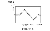
- FIG. 5 is a diagram showing a drive pattern in which a tremor pattern and a drift pattern are combined.
- the optical measuring apparatus 100 can set any one of the above-described tremor pattern, drift pattern, and flick pattern driving patterns to the following first to tenth driving methods.
- the drive pattern may be set in advance or may be set by the user.
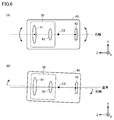
- FIG. 6 is a diagram schematically showing a driving mode of the first driving method.
- the optical measurement apparatus 100 rotates the entire optical unit 40 around the point C2 on the optical axis in the optical unit 40. To do. As a result, the optical measurement apparatus 100 drives the lenses 41 and 43 and the imaging device 45 to rotate around the point C2 on the optical axis of the lenses 41 and 43. Preferably, the optical measuring device 100 repeats the clockwise rotation and the counterclockwise rotation of the optical unit 40. As a result, the optical measurement apparatus 100 can reciprocate the lenses 41 and 43 and the image sensor 45.
- the rotation of the optical unit 40 is realized by the rotation of a cam that is in contact with the optical unit 40. As the cam rotates, the optical unit 40 is driven in conjunction with the cam.
- the optical measuring device 100 sequentially images the measurement object while rotating the optical unit 40 around the point C2. Thereby, the optical measuring device 100 can image the measurement object from various directions.
- the optical measurement apparatus 100 measures changes in the reflectance of the surface of the measurement object, the degree of unevenness of the surface of the measurement object, and the like based on output images obtained by imaging the measurement object from various directions. Can do.
- FIG. 6 shows an example in which the optical unit 40 is rotationally driven on the YZ plane.
- the optical unit 40 may be rotationally driven on other planes or may be rotated three-dimensionally. It may be driven.
- FIG. 7 is a diagram schematically showing a driving mode of the second driving method.
- the center of rotation exists in the optical unit 40.
- the rotation center exists outside the optical unit 40. Since other points are the same as those of the first driving method, description thereof will not be repeated below.
- the optical measurement apparatus 100 rotates the entire optical unit 40 around a point C3 on the optical axis outside the optical unit 40. To do.
- the optical measurement apparatus 100 drives the lenses 41 and 43 and the image sensor 45 to rotate around the point C3 on the optical axis of the lenses 41 and 43.
- the point C3 is a point on the surface of the measurement object 35.
- the optical measurement apparatus 100 sequentially images the measurement object 35 while the optical unit 40 is rotationally driven around the point C3. Thereby, the optical measuring device 100 can image the measurement object 35 from various directions.
- the optical measurement apparatus 100 measures changes in the reflectance of the surface of the measurement object, the degree of unevenness of the surface of the measurement object, and the like based on output images obtained by imaging the measurement object from various directions. Can do. Further, since the point C3 on the measurement object is the center of rotation, the position of the measurement object does not change between output images. Therefore, it becomes easy to align the measurement object between the output images.
- FIG. 7 shows an example in which the optical unit 40 is rotationally driven on the YZ plane.
- the optical unit 40 may be rotationally driven on another plane, or may be rotated three-dimensionally. It may be driven.
- FIG. 8 is a diagram schematically showing a driving mode of the third driving method.
- the optical measurement apparatus 100 rotates the image sensor 45 around the point C4 on the optical axis in the optical unit 40. At this time, the lenses 41 and 43 are not driven. Thereby, the positional relationship between the lenses 41 and 43 and the image sensor 45 changes.
- the optical measurement apparatus 100 repeats the clockwise rotation and the counterclockwise rotation of the image sensor 45. Thereby, the optical measurement apparatus 100 can reciprocate the image sensor 45.
- the optical measurement apparatus 100 sequentially images the measurement object while the image sensor 45 is rotationally driven around the point C4.
- FIG. 8 shows an example in which the image sensor 45 is rotationally driven on the YZ plane.
- the image sensor 45 may be rotationally driven on another plane, or may be rotated three-dimensionally. It may be driven.
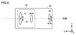
- FIG. 9 is a diagram schematically showing a driving mode of the fourth driving method.
- the drive target was rotationally driven.
- the drive target is translated. Since the other points are the same as those of the first to third driving methods, description thereof will not be repeated below.
- the optical measuring device 100 drives the lenses 41 and 43 and the image sensor 45 individually. More specifically, the optical measurement apparatus 100 drives at least one drive target of the lenses 41 and 43 and the image sensor 45 in a direction orthogonal to the optical axes of the lenses 41 and 43.
- the lens 41 is driven to reciprocate in the Y direction.
- the lens 43 is driven to reciprocate in the optical axis direction (that is, the Z direction).
- the image sensor 45 is driven to reciprocate in the X direction or the Y direction.
- the optical measurement apparatus 100 sequentially images the measurement object while reciprocatingly driving at least one of the lenses 41 and 43 and the image sensor 45.
- FIG. 9 shows an example in which the lens 41 is reciprocated in the Y direction, the lens 41 may be reciprocated in other directions.
- FIG. 9 shows an example in which the lens 43 is reciprocated in the Z direction, but the lens 43 may be reciprocated in other directions.
- FIG. 9 shows an example in which the image sensor 45 is reciprocated in the Y and Z directions, but the lens 41 may be reciprocated in other directions.
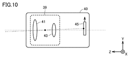
- FIG. 10 is a diagram schematically illustrating a driving mode of the fifth driving method.
- the lenses 41 and 43 and the image sensor 45 are individually translated.
- the image sensor 45 moves in parallel. Since the other points are the same as those of the fourth driving method, description thereof will not be repeated below.
- the optical measuring device 100 reciprocates the image sensor 45 in the direction orthogonal to the optical axis.
- the image sensor 45 is driven by a so-called parent turtle method.
- the actuator 46 (see FIG. 2) of the image sensor 45 includes a first flat plate for holding the image sensor 45 and a second flat plate for holding the first flat plate.
- the first flat plate drives the image sensor 45 in the X direction by SIDM (Smooth Impact Drive Mechanism) or the like.
- the second flat plate drives the first flat plate in the Y direction by SIDM or the like, and drives the image sensor 45 in the Y direction.
- the image sensor 45 is driven in an arbitrary direction on the XY plane by individually driving the first flat plate and the second flat plate.
- the optical measurement apparatus 100 sequentially images the measurement object while the image sensor 45 is driven to reciprocate in a predetermined direction on the XY plane.
- FIG. 10 shows an example in which the image sensor 45 is reciprocated in the Y direction, the image sensor 45 may be reciprocated in other directions.
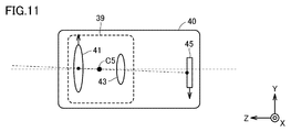
- FIG. 11 is a diagram schematically illustrating a driving mode of the sixth driving method.
- the lenses 41 and 43 and the image sensor 45 were not interlocked.
- the lenses 41 and 43 and the image sensor 45 are driven in conjunction with each other. Since the other points are the same as those of the fourth and fifth drive systems, description thereof will not be repeated below.
- the optical measuring device 100 drives the lens 41 and the image sensor 45 in opposite directions.
- the lens 41 is driven by a drive unit 42 (see FIG. 2).
- the image sensor 45 is driven by a drive unit 47 (see FIG. 2).
- the optical measuring apparatus 100 sequentially images the measurement object while the lens 41 and the image sensor 45 are reciprocated in opposite directions.
- the optical measurement apparatus 100 reduces the drive amount as the drive target is closer to the reference point C5 on the optical axis.
- the optical measurement apparatus 100 makes the driving amount of the lens 41 closer to the reference point C ⁇ b> 5 smaller than the driving amount of the image sensor 45.
- the drive amount of the drive target is proportional to the distance from the reference point C5 to the drive target.
- FIG. 11 shows an example in which the lens 41 and the image sensor 45 are linked in opposite directions in the Y direction. However, the lens 41 and the image sensor 45 are linked in opposite directions in the other directions. It may be configured to.
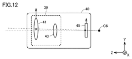
- FIG. 12 is a diagram schematically showing a driving mode of the seventh driving method.
- the lens 41 and the image sensor 45 are driven in opposite directions.
- the lens 41 and the image sensor 45 are driven in the same direction. Since other points are the same as those of the sixth driving method, description thereof will not be repeated below.
- the optical measuring device 100 drives the lens 41 and the image sensor 45 in the same direction.
- the lens 41 is driven by a drive unit 42 (see FIG. 2).
- the image sensor 45 is driven by a drive unit 47 (see FIG. 2).
- the optical measurement device 100 sequentially images the measurement object while the lens 41 and the image sensor 45 are reciprocally driven in the same direction.
- the optical measuring device 100 reduces the driving amount per time as the driving target is closer to the reference point C6 on the optical axis.
- the optical measurement apparatus 100 makes the drive amount of the image sensor 45 closer to the reference point C ⁇ b> 6 smaller than the drive amount of the lens 41.
- the drive amount of the drive target is proportional to the distance from the reference point C6 to the drive target.
- FIG. 12 shows an example in which the lens 41 and the image sensor 45 are linked in the same direction in the Y direction. However, the lens 41 and the image sensor 45 are linked in the same direction in the other directions. It may be configured to.
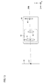
- FIG. 13 is a diagram schematically showing a driving mode of the eighth driving method.
- the drive reference point C6 was closer to the image sensor 45 than the lens 41.
- the driving reference point C7 is closer to the lens 41 than the image sensor 45 is. Since the other points are the same as those of the seventh drive method, description thereof will not be repeated below.
- the optical measurement device 100 drives the lens 41 and the image sensor 45 in the same direction.
- the lens 41 is driven by a drive unit 42 (see FIG. 2).
- the image sensor 45 is driven by a drive unit 47 (see FIG. 2).
- the optical measurement device 100 sequentially images the measurement object while the lens 41 and the image sensor 45 are reciprocally driven in the same direction.
- the optical measuring apparatus 100 drives the lens 41 and the image sensor 45 with reference to the reference point C7.
- the reference point C7 exists on the optical axis of the lenses 41 and 43 and exists on the measurement object.
- the optical measuring device 100 reduces the drive amount as the drive target is closer to the reference point C7 on the optical axis.
- the optical measurement apparatus 100 makes the driving amount of the lens 41 near the reference point C7 smaller than the driving amount of the image sensor 45. More preferably, the drive amount of the drive target is proportional to the distance from the reference point C7 to the drive target.
- FIG. 13 shows an example in which the lens 41 and the image sensor 45 are linked in the same direction in the Y direction. However, the lens 41 and the image sensor 45 are linked in the same direction in the other directions. It may be configured to.
- the ninth drive method will be described with reference to FIGS.
- the image sensor 45 is driven to rotate or translate.
- the image sensor 45 is driven to swing. Since the other points are the same as the above-described driving method, description thereof will not be repeated below.
- FIG. 14 is a diagram schematically showing a driving mode of the ninth driving method.
- the image sensor 45 is driven by an actuator 46.
- the actuator 46 drives the image sensor 45 so that the light receiving surface of the image sensor 45 is inclined with respect to the optical axes of the lenses 41 and 43.
- the actuator 46 swings the image sensor 45.
- the optical measuring device 100 sequentially images the measurement object while the image sensor 45 is swung.
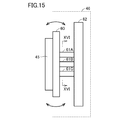
- FIG. 15 is a view showing an example of the structure of the actuator 46.
- 16 is a cross-sectional view taken along line XVI-XVI in FIG.
- the actuator 46 includes a substrate 60 that holds the image sensor 45, piezoelectric elements 61 ⁇ / b> A to 61 ⁇ / b> C, and a base member 62.
- the image sensor 45 is disposed on one surface of the substrate 60.
- One end of the piezoelectric element 61A, one end of the piezoelectric element 61B, and one end of the piezoelectric element 61C are connected to the other surface of the substrate 60.
- the other end of the piezoelectric element 61A, the other end of the piezoelectric element 61B, and the other end of the piezoelectric element 61C are connected to the base member 62.
- Each of the piezoelectric elements 61A to 61C expands and contracts when a voltage is applied.
- the drive unit 47 (see FIG.
- the imaging element 45 can be swung in an arbitrary direction.
- FIGS. 15 and 16 an example in which three piezoelectric elements 61A to 61C are provided is shown, but the number of piezoelectric elements is not limited to three. Two or more piezoelectric elements may be used. When the number of piezoelectric elements is two, the imaging element 45 is swung in one direction.
- FIG. 17 is a diagram schematically showing a driving mode of the tenth driving method.
- the image sensor 45 is driven in the X direction.
- the image sensor 45 is driven in the Z direction, which is the optical axis direction.
- the image sensor 45 is driven by the drive unit 47 (see FIG. 2) described above.
- the drive unit 47 is a motor, a plunger, a piezoelectric element, or a combination thereof.
- the drive unit 47 drives the image sensor 45 along the optical axis while maintaining a state where the light receiving surface of the image sensor 45 is orthogonal to the optical axes of the lenses 41 and 43.
- the optical measuring device 100 sequentially images the measurement object while the image sensor 45 is driven to reciprocate on the optical axis. As a result, the imaging position changes back and forth on the optical axis. As a result, the optical measurement apparatus 100 can generate a plurality of output images whose focal points are slightly shifted.
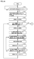
- FIG. 18 is a flowchart showing a process of generating an output image.
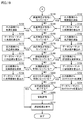
- FIG. 19 is a flowchart showing a process of calculating the optical measurement value of the measurement object.
- the processing in FIGS. 18 and 19 is realized by the control unit 101 (see FIG. 2) executing a program. In other aspects, some or all of the processing may be performed by circuit elements or other hardware.
- step S100 the control unit 101 determines whether or not the type of the measurement object has been received.
- the display unit 52 of the optical measurement apparatus 100 displays a candidate for the type of measurement object. By displaying candidates for the type of measurement object in a list, it is easy to confirm the candidates. The user selects the type of the measurement object from the candidates displayed on the display unit 52 by touching the display unit 52 or operating the operation unit 53.
- control unit 101 determines that the type of measurement object has been received (YES in step S100)
- control unit 101 switches control to step S102.
- the control part 101 performs the process of step S100 again.
- step S102 the control unit 101 acquires a drive pattern corresponding to the type of the measurement object.
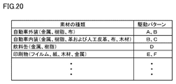
- the drive pattern is acquired from, for example, the material database 110 shown in FIG.
- FIG. 20 is a diagram illustrating an example of the material database 110.
- a driving pattern to be driven is associated with each type of material.
- the material database 110 may include sensory evaluation results for each material.
- the evaluation result is a result evaluated in advance by a person.
- the types of sensory values to be evaluated include, for example, moist feeling, smoothness, glossiness, or overall evaluation thereof.
- the material database 110 includes an optical measurement result of each material, a calculation formula for calculating a sensory value from the optical measurement value, or a correlation function calculated from a correlation between the optical measurement value and the sensory evaluation. Etc. may be included.
- the material database 110 is stored in the optical measurement device 100.
- the control unit 101 acquires the material database 110 from the optical measurement device 100.
- the control unit 101 acquires a drive pattern corresponding to the type of the measurement object from a plurality of drive patterns defined in the material database 110.
- the control unit 101 determines the identified drive pattern as a drive pattern to be driven.
- the material database 110 is stored in an external device such as the server 150 (see FIG. 22) or the PC 200 (see FIG. 2).
- the optical measurement apparatus 100 selects a drive pattern corresponding to the type of the measurement object from among a plurality of drive patterns stored in the server 150 via the communication interface 54 (see FIG. 2) that is a communication unit.
- a request for acquisition (hereinafter also referred to as “acquisition request”) is transmitted to the server 150.
- the server 150 Based on the reception of the acquisition request from the optical measurement apparatus 100, the server 150 identifies the drive pattern corresponding to the type of the measurement object from among the plurality of drive patterns defined in the material database 110, and identifies The drive pattern thus transmitted is transmitted to the optical measurement apparatus 100.
- the optical measurement apparatus 100 receives a drive pattern corresponding to the type of the measurement object as a drive pattern of the drive target from the server 150 via the communication interface 54 which is a communication unit.
- step S104 the control unit 101 initializes a variable N1 representing a drive pattern number.
- the variable N1 is initialized to zero, for example.
- the plurality of drive patterns are uniquely identified by the variable N1.
- step S110 the control unit 101 determines whether or not the drive target is driven with all the drive patterns acquired in step S102.
- the control unit 101 determines that the drive target is driven with all the drive patterns acquired in step S102 (YES in step S110)
- the control unit 101 switches the control to step S140.
- the control part 101 switches control to step S112.
- step S112 the control unit 101 initializes a variable N2 representing the step number of each drive pattern.
- the variable N2 is initialized to zero, for example.
- Each drive pattern includes a plurality of drive steps, and each drive step of the drive pattern is uniquely identified by a variable N2.
- Each drive step is associated with a drive amount to be driven.
- the drive amount of the drive target is, for example, the amount of movement in the X direction, the amount of movement in the Y direction, the amount of movement in the Z direction, the rotation angle around the X axis, the rotation angle around the Y axis, and the rotation angle around the Y axis. Represented.
- the optical measurement apparatus 100 adjusts to the new lens based on the replacement of the lenses 41 and 43 with a new lens.
- the drive amount specified for each drive step is corrected. More specifically, the optical measurement apparatus 100 receives data indicating the optical characteristics of a new lens from the server 150 (see FIG. 22) or the like, and the driving amount defined in each driving step based on the data. Correct.
- step S114 the control unit 101 specifies the “N1” th drive pattern identified by the variable N1 from the drive patterns acquired in step S102, and starts driving the drive target according to the specified drive pattern. To do.
- step S116 the control unit 101 drives the drive target according to the drive amount corresponding to the “N2” th drive step identified by the variable N2.
- step S118 the control unit 101 images the measurement object. Thereby, one output image is generated. That is, each time step S118 is executed, one output image is generated.
- step S120 the control unit 101 increments the variable N2. That is, the control unit 101 increases the variable N2 by “1”.
- step S130 the control unit 101 determines whether all driving steps in the “N1” th driving pattern have been executed. As an example, this determination is made based on whether or not the variable N2 has reached the driving step number m (see FIG. 21).
- control unit 101 determines that all the drive steps in the “N1” -th drive pattern have been executed (YES in step S130)
- control unit 101 switches control to step S132. If not (NO in step S130), control unit 101 returns control to step S116.
- step S132 the control unit 101 increments the variable N1. That is, the control unit 101 increases the variable N1 by “1”.
- step S140 the control unit 101 determines whether luminance measurement is enabled. When control unit 101 determines that the luminance measurement is valid (YES in step S140), control unit 101 switches control to step S142. If not (NO in step S140), control unit 101 switches control to step S150.
- step S142 the control unit 101 calculates the luminance of the measurement object from the plurality of output images obtained by the process in step S118.
- the method for calculating the luminance is arbitrary.
- the control unit 101 calculates the luminance of the measurement object by averaging the pixel values of the output images.
- the control unit 101 specifies an area in which the measurement object is captured using an image processing technique such as template matching in each output image, and determines an average value of pixel values of the specified area of the measurement object. Calculated as luminance.
- step S144 the control unit 101 writes the luminance value calculated in step S142 in the data format 112 shown in FIG.
- FIG. 21 is a diagram illustrating an example of the data format 112.
- the control unit 101 includes a data number for identifying data, a material name, a measurement date and time of a measurement object, and identification information for identifying the type of material (for example, a material database Name), measurement items of the optical measuring apparatus 100, identification information for identifying the drive pattern (for example, drive pattern name), and control data used for controlling the drive target are written in the data format 112.
- step S150 the control unit 101 determines whether chromaticity measurement is enabled. When it is determined that chromaticity measurement is enabled (YES in step S150), control unit 101 switches control to step S152. If not (NO in step S150), control unit 101 switches control to step S160.
- step S152 the control unit 101 calculates the chromaticity of the measurement object from the plurality of output images obtained by the process in step S118.
- the chromaticity can be calculated when the output image is a color image.
- the calculation method of chromaticity is arbitrary.
- each output image includes an R image representing the red component of the measurement object, a G image representing the green component of the measurement object, and a B image representing the blue component of the measurement object.
- the control unit 101 calculates an average value obtained by averaging the pixel values of each R image, an average value obtained by averaging the pixel values of each G image, and an average obtained by averaging the pixel values of each B image.
- the ratio with the value is calculated as chromaticity.
- step S154 the control unit 101 writes the chromaticity calculated in step S152 in the data format 112.
- the control unit 101 controls the measurement items of the optical measurement apparatus 100, identification information for identifying the drive pattern (for example, drive pattern name), and the control used for controlling the drive target. Write data to data format 112.
- step S160 the control unit 101 determines whether gloss measurement is enabled. When it is determined that gloss measurement is enabled (YES in step S160), control unit 101 switches control to step S162. If not (NO in step S160), control unit 101 switches control to step S170.
- step S162 the control unit 101 calculates the glossiness of the measurement object from the plurality of output images obtained by the process in step S118.
- the method for calculating the glossiness is arbitrary. As an example, the control unit 101 counts pixels whose pixel values exceed a predetermined value for each output image, and calculates glossiness by averaging the count results.
- step S164 the control unit 101 writes the glossiness calculated in step S162 in the data format 112.
- the control unit 101 controls the measurement items of the optical measurement apparatus 100, identification information for identifying the drive pattern (for example, the drive pattern name), and the control used for controlling the drive target, in addition to the glossiness. Write data to data format 112.
- step S170 the control unit 101 determines whether or not unevenness measurement (so-called yuzu skin measurement) is enabled.
- control unit 101 determines that unevenness measurement is enabled (YES in step S170)
- control unit 101 switches control to step S172. If not (NO in step S170), control unit 101 switches control to step S180.
- step S172 the control unit 101 calculates the degree of unevenness of the measurement object from the plurality of output images obtained by the process in step S118.
- the method for calculating the degree of unevenness is arbitrary.
- the control unit 101 calculates the degree of unevenness of the measurement object from an output image obtained by imaging the measurement object from different directions.
- the degree of unevenness is large, a change in pixel value is large between output images obtained by imaging from different directions.
- the degree of unevenness is small, the change in pixel value between output images obtained by imaging from different directions becomes small.
- control unit 101 calculates the degree of change in pixel value between output images obtained by imaging from different directions, and calculates the degree of unevenness of the measurement object based on the degree of change.
- the unevenness degree is calculated after the position of the measurement object in the output image is matched between the output images.
- step S174 the control unit 101 writes the unevenness calculated in step S172 in the data format 112.
- the control unit 101 controls the measurement items of the optical measurement apparatus 100, identification information for identifying the drive pattern (for example, the drive pattern name), and the control used for controlling the drive target in addition to the unevenness degree. Write data to data format 112.
- step S180 the control unit 101 determines whether sharpness measurement is enabled.
- control unit 101 determines that sharpness measurement is enabled (YES in step S180)
- control unit 101 switches control to step S182. Otherwise (NO in step S180), control unit 101 switches control to step S190.
- step S182 the control unit 101 calculates the sharpness of the measurement object from the plurality of output images obtained by the process in step S118.
- the method for calculating the sharpness is arbitrary.
- the control unit 101 calculates the degree of change in pixel value between output images obtained by imaging a measurement object with different focal points. The greater the degree of change, the higher the sharpness, and the lower the degree of change, the lower the sharpness.
- the unevenness degree is calculated after the position of the measurement object in the output image is matched between the output images.
- step S184 the control unit 101 writes the sharpness calculated in step S182 in the data format 112.
- the control unit 101 in addition to the sharpness, the measurement item of the optical measurement apparatus 100, identification information for identifying the drive pattern (for example, drive pattern name), and the control used for controlling the drive target Write data to data format 112.
- step S190 the control unit 101 determines whether or not brightness measurement is enabled. When it is determined that the glitter measurement is valid (YES in step S190), control unit 101 switches control to step S192. If not (NO in step S190), control unit 101 switches control to step S200.
- step S192 the control unit 101 calculates the brightness value of the measurement object from the plurality of output images obtained by the process in step S118.
- the method for calculating the glitter value is arbitrary.
- the glitter feeling is calculated based on an output image obtained by driving a drive target with the above-described drift pattern.
- the measurement object is imaged at intervals of 100 ⁇ m to 500 ⁇ m while driving the imaging surface of the image sensor 45 with a drift pattern. As a result, a predetermined number (for example, five) of output images are obtained.
- the control unit 101 calculates luminance (for example, reflectance or brightness) for each output image.
- the control unit 101 calculates a glitter value from the calculated brightness based on a predetermined correlation between the glitter value and the brightness.
- step S194 the control unit 101 writes the brightness value calculated in step S192 in the data format 112.
- the control unit 101 is used for controlling the measurement item of the optical measurement apparatus 100, identification information for identifying the drive pattern (for example, the drive pattern name), and the drive target in addition to the glitter value. Write control data to data format 112.
- step S200 the control unit 101 determines whether or not 3D texture measurement is enabled. When it is determined that 3D texture measurement is enabled (YES in step S200), control unit 101 switches control to step S202. If not (NO in step S200), control unit 101 switches control to step S210.
- step S202 the control unit 101 generates a 3D texture of the measurement object from the plurality of output images obtained by the process in step S118.
- the method for generating the 3D texture is arbitrary.
- the control unit 101 generates a 3D image representing the measurement object as a 3D texture using disparity information between output images obtained by imaging the measurement object from different viewpoints.
- step S204 the control unit 101 writes the 3D texture generated in step S202 in the data format 112.
- the control unit 101 stores the measurement items of the optical measurement apparatus 100, identification information for identifying the drive pattern (for example, drive pattern name), and control data used for controlling the drive target. Write to format 112.
- step S210 the control unit 101 determines whether or not to end the optical measurement process.
- control unit 101 determines to end the optical measurement process (YES in step S210)
- control unit 101 switches control to step S222. Otherwise (NO in step S210), control unit 101 switches control to step S220.
- step S220 the control unit 101 performs sensory evaluation of the measurement object based on the measurement result (for example, luminance) of the measurement object. Details of the sensory evaluation will be described later.
- step S222 the control unit 101 causes the display unit 52 of the optical measurement apparatus 100 to display the measurement result.
- the display unit 52 calculates the luminance value calculated in Step S142, the chromaticity calculated in Step S152, the gloss value calculated in Step S162, the unevenness calculated in Step S172, and the degree of unevenness calculated in Step S182.
- the sharpness, the brightness value calculated in step S192, the 3D texture generated in step S202, the sensory value obtained in step S220, and the like are displayed.
- the sensory evaluation may be executed by the optical measurement device 100, or may be executed by the server 150 or the PC 200 (see FIG. 2) that can communicate with the optical measurement device 100.
- FIG. 22 is a sequence diagram illustrating a data flow between the optical measurement apparatus 100 and the server 150.
- step S300 the optical measurement apparatus 100 transmits the data format 112 to the server 150.
- Communication between the optical measurement apparatus 100 and the server 150 may be realized by wired communication or wireless communication.
- step S302 the server 150 writes the contents of the data format 112 received from the optical measurement apparatus 100 into the material database 110 (see FIG. 20).
- step S304 the server 150 performs sensory evaluation of the measurement object based on the optical measurement result included in the data format 112.
- the method for sensory evaluation is arbitrary.
- the evaluator gives a sensory value subjectively to an image for each material in advance.
- the sensory values to be given are, for example, an evaluation value representing texture, an evaluation value representing moist feeling, an evaluation value representing smoothness, an evaluation value representing glossiness, and the like.
- the server 150 measures the optical measurement value for each image to which the sensory value is given.
- the optical measurement values to be measured are, for example, a luminance value, chromaticity, gloss value, unevenness degree, sharpness, and glitter value.
- the server 150 calculates a correlation expression representing a correlation between the given sensory value and the measured optical measurement value.
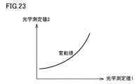
- FIG. 23 is a diagram illustrating an example of the correlation between the optical measurement value and the sensory value.
- the server 150 associates the optical measurement value with the correlation formula for each type of material, and stores them in the material database 110. The process of learning such a correlation equation is performed in advance before measuring the sensory value of the measurement object.
- the server 150 acquires a correlation equation corresponding to the same type of material as the object to be measured from the correlation equations defined in the material database 110, and acquires an optical measurement value from the data format 112.
- the server 150 calculates the sensory value of the measurement object by substituting the optical measurement value acquired from the data format 112 into the correlation equation acquired from the material database 110.
- the server 150 learns the correlation between the optical measurement value and the sensory value in advance, and based on the learned correlation and the optical measurement value measured for the measurement object, The sensory value of the measurement object is calculated.
- the sensory value to be measured is configured to be selectable.
- step S306 the server 150 transmits the sensory value calculated in step S304 to the optical measurement device 100.
- optical measurement apparatus 100 sequentially moves the measurement object while reciprocating at least one drive object of lenses 41 and 43 and imaging element 45 according to a predetermined drive pattern. Take an image. Thereby, the optical measuring device 100 can image the measurement object under various conditions.
- the optical measurement apparatus 100 can image the measurement object while changing the focus by moving the drive object on the optical axis. Further, the optical measurement apparatus 100 can image the measurement object from various directions by rotating the drive object around a predetermined point on the optical axis. As a result, the optical measurement apparatus 100 can measure a change in reflectance on the surface of the measurement object, a degree of unevenness on the surface of the measurement object, and the like.
- FIG. 24 is a diagram showing an internal configuration of the optical measurement apparatus 100A according to the second embodiment.
- Optical measurement apparatus 100A according to the second embodiment differs from optical measurement apparatus 100 according to the first embodiment in that the measurement object is imaged in a state where optical measurement apparatus 100A is in contact with the measurement object. Since the other points are the same as those of the optical measuring apparatus 100, the description thereof will not be repeated below.
- the optical measuring device 100A includes a housing 50A.
- the above-described optical unit 40 and light sources 70A and 70B are provided inside the housing 50A.
- the light sources 70A and 70B each illuminate the measurement object from different directions.
- a stabilizing plate 71 is provided in the housing 50A. By providing the stabilization plate 71, the optical measurement device 100 ⁇ / b> A is stabilized when the user brings the optical measurement device 100 ⁇ / b> A into contact with the measurement object.
- the optical measuring device 100A starts driving the optical unit 40 according to a predetermined driving pattern when receiving an instruction for imaging the measurement object.
- the optical measuring device 100A repeats the clockwise rotation and the counterclockwise rotation of the optical unit 40 around the point C8.
- the drive target in the optical unit 40 is reciprocated.
- the optical measurement apparatus 100A sequentially images the measurement object while the drive object is reciprocatingly driven. Thereby, the optical measuring device 100A can image the measurement object under various conditions.
- the optical measurement device 100A measures various optical measurement values of the measurement object based on an output image obtained by imaging the measurement object.
- an example in which the optical measurement apparatus 100A measures glossiness, which is an example of an optical measurement value, will be described.
- the object to be measured is painted with metallic or pearl, if the quantity or arrangement of glittering materials (for example, aluminum flakes, mica, etc.) contained in the paint is different, the way the object to be measured looks like lighting It varies depending on the direction of light and the angle at which the measurement object is viewed. Therefore, even if the measurement object is painted in the same way, it may appear different colors.
- glittering materials for example, aluminum flakes, mica, etc.
- the optical measuring device 100A determines the quality of the measurement object by comparing the glossiness measured for the standard sample prepared in advance with the glossiness measured for the measurement object. More specifically, the optical measurement apparatus 100A irradiates light from a predetermined direction by the light sources 70A and 70B and images the standard sample while reciprocating the optical unit 40. The optical measurement apparatus 100A can artificially move the optical unit 40 by moving the optical unit 40 back and forth, and can image a standard sample from various directions.
- the optical measurement apparatus 100A When the standard sample is imaged from different directions, the position of the pixel with a high luminance value changes. In addition, the number of pixels having a high luminance value also changes.
- the optical measurement apparatus 100A counts pixels whose pixel values are higher than a predetermined value for each output image. Thereby, the optical measuring device 100A can specify the brightness (glossiness) of the standard sample.
- the optical measuring device 100A calculates a difference or change rate of count values between output images obtained by imaging standard samples from adjacent angles.
- the optical measurement apparatus 100A stores the information in the material database 110 (see FIG. 20) after associating the difference or change rate of the count value with the type of the standard sample.
- the optical measuring device 100A calculates the difference or rate of change of the count value for the measurement object based on receiving the measurement instruction for the measurement object.
- the optical measurement apparatus 100A compares the difference or change rate of the count value obtained for the measurement object with the difference or change rate of the count value measured for the standard sample.
- the optical measurement apparatus 100A determines that the measurement object is a non-defective product as the difference or change rate of the count value obtained for the measurement object is closer to the difference or change rate of the count value measured for the standard sample. To do.
- the optical measurement apparatus 100A evaluates the quality of the measurement object based on the change in the size of the high-luminance region, so that it is not necessary to align the measurement object between the output images.
- An optical measurement apparatus includes a lens for imaging reflected light from a measurement object, an imaging element for receiving the reflected light that has passed through the lens and generating an image representing the measurement object, and the lens And a drive unit for driving at least one drive target of the image sensor, and a control unit for controlling the optical measurement device.
- the control unit acquires a plurality of the images generated by sequentially imaging the measurement object while the driving unit is driving the driving target according to a predetermined driving pattern from the imaging element, and The image is output.
- the drive unit drives the drive target in a direction orthogonal to the optical axis of the lens.
- the driving unit drives the lens and the imaging element in opposite directions.
- the drive unit drives the lens and the image sensor in the same direction.
- the driving unit rotates around the lens and a predetermined point on the optical axis of the imaging element.
- the driving unit drives the imaging element so that a light receiving surface of the imaging element is inclined with respect to the optical axis of the lens.
- the drive unit drives the image sensor along the optical axis while maintaining a state where the light receiving surface of the image sensor is orthogonal to the optical axis of the lens.
- control unit selects two or more drive patterns as the predetermined drive pattern from among a plurality of drive patterns different from each other.
- the plurality of drive patterns include at least two of a first drive pattern, a second drive pattern, and a third drive pattern.
- the period of the drive target according to the first drive pattern is shorter than the period of the drive target according to the second drive pattern.
- the amplitude of the drive target according to the first drive pattern is smaller than the amplitude of the drive target according to the second drive pattern.
- the amplitude of the drive target according to the first drive pattern is smaller than the amplitude of the drive target according to the third drive pattern.
- the maximum value of the moving speed of the driving target according to the first driving pattern is smaller than the maximum value of the moving speed of the driving target according to the third driving pattern.
- an object type is associated in advance with each of the plurality of drive patterns.
- the control unit receives the type of the measurement object and selects a drive pattern corresponding to the type of the measurement object as the predetermined drive pattern from the plurality of drive patterns.
- the optical measurement apparatus further includes a display unit for displaying candidates for the type of the measurement object.
- the control unit receives the type of the measurement object from the candidates displayed on the display unit.
- the optical measurement device further includes a communication unit for communicating with the server.
- the server stores the drive pattern for each type of object.
- the communication unit transmits a request for acquiring a drive pattern corresponding to the type of the measurement object from the plurality of drive patterns stored in the server to the server, and receives the request.
- a drive pattern corresponding to the type of the measurement object is received from the server as the predetermined drive pattern.
- 35 measurement object 40 optical unit, 41, 43 lens, 42, 44, 47 drive unit, 45 image sensor, 46 actuator, 48 conversion circuit, 49 image processing unit, 50, 50A housing, 51 optical system, 52 display Unit, 53 operation unit, 54 communication interface, 55 power supply, 56 storage unit, 58 image generation program, 59 drive pattern, 60 substrate, 61A-61C piezoelectric element, 62 base member, 70A, 70B light source, 71 stabilizer, 100, 100A optical measurement device, 101 control unit, 110 material database, 112 data format, 150 server, 200 PC, 300 eyeball, 301 lens, 302 retina, 311 to 313 graph.
Landscapes
- Physics & Mathematics (AREA)
- General Physics & Mathematics (AREA)
- Engineering & Computer Science (AREA)
- Multimedia (AREA)
- Signal Processing (AREA)
- Analytical Chemistry (AREA)
- Life Sciences & Earth Sciences (AREA)
- Chemical & Material Sciences (AREA)
- Health & Medical Sciences (AREA)
- Biochemistry (AREA)
- General Health & Medical Sciences (AREA)
- Immunology (AREA)
- Pathology (AREA)
- Mathematical Physics (AREA)
- Theoretical Computer Science (AREA)
- Spectroscopy & Molecular Physics (AREA)
- Studio Devices (AREA)
- Investigating Or Analysing Materials By Optical Means (AREA)
Abstract
様々な条件で測定対象物を撮像することが可能な光学測定装置を提供する。光学測定装置(100)は、測定対象物からの反射光を結像するためのレンズ(41)と、レンズ(41)を通過した反射光を受けて測定対象物を表わす画像を生成するための撮像素子(45)と、レンズ(41)および撮像素子(45)の少なくとも1つの駆動対象を駆動するための駆動部(42,47)と、光学測定装置を制御するための制御部(101)とを備える。制御部(101)は、駆動部(42,47)が所定の駆動パターンに従って駆動対象を駆動している間に測定対象物を順次撮像して生成される複数の画像を撮像素子(45)から取得し、複数の当該画像を出力する。
Description
本開示は、光学測定装置の制御に関し、特に、画像を生成することが可能な光学測定装置の制御に関する。
測定対象物の欠陥を検出することが可能な光学測定装置が普及している。測定対象物の欠陥を検出するための技術に関し、特開2013-185862号公報(特許文献1)は、「高速に、高感度に欠陥を検出することが可能な」検査装置を開示している。当該検査装置は、測定対象物を撮像して得られた画像に対して画像処理を実行し、測定対象物の欠陥を検出する。
作業者は、測定対象物の欠陥を目視で確認するとき、測定対象物を様々な角度から確認する。このとき、作業者は、測定対象物を目視して得られる光学的な情報(たとえば、反射光の変化など)を総合して測定対象物の欠陥を探す。特許文献1に開示される検査装置は、撮像部が固定されているため、測定対象物を一点からしか撮像することしかできない。そのため、当該検査装置は、人間と同様の光学的情報を得ることができない。したがって、様々な条件で測定対象物を撮像することが可能な光学測定装置が望まれている。
本開示は上述のような問題点を解決するためになされたものであって、ある局面における目的は、様々な条件で測定対象物を撮像することが可能な光学測定装置を提供することである。他の局面における目的は、様々な条件で測定対象物を撮像することが可能な撮像装置による画像の生成方法を提供することである。さらに他の局面における目的は、様々な条件で測定対象物を撮像することが可能な撮像装置による画像の生成プログラムを提供することである。
光学測定装置は、測定対象物からの反射光を結像するためのレンズと、上記レンズを通過した上記反射光を受けて上記測定対象物を表わす画像を生成するための撮像素子と、上記レンズおよび上記撮像素子の少なくとも1つの駆動対象を駆動するための駆動部と、上記光学測定装置を制御するための制御部とを備える。上記制御部は、上記駆動部が所定の駆動パターンに従って上記駆動対象を駆動している間に上記測定対象物を順次撮像して生成される複数の上記画像を上記撮像素子から取得し、複数の当該画像を出力する。
他の局面に従うと、撮像装置による画像の生成方法が提供される。上記撮像装置は、測定対象物からの反射光を結像するためのレンズと、上記レンズを通過した上記反射光を受けて上記測定対象物を表わす画像を生成するための撮像素子とを備える。上記生成方法は、上記レンズおよび上記撮像素子の少なくとも1つの駆動対象を所定の駆動パターンに従って駆動するステップと、上記駆動対象が上記所定の駆動パターンに従って駆動している間に上記撮像素子に上記測定対象物を順次撮像させ、上記撮像素子から複数の上記画像を取得するステップと、複数の上記画像を出力するステップとを備える。
さらに他の局面に従うと、撮像装置による画像の生成プログラムが提供される。上記撮像装置は、測定対象物からの反射光を結像するためのレンズと、上記レンズを通過した上記反射光を受けて上記測定対象物を表わす画像を生成するための撮像素子とを備える。上記生成プログラムは、上記撮像装置に、上記レンズおよび上記撮像素子の少なくとも1つの駆動対象を所定の駆動パターンに従って駆動するステップと、上記駆動対象が上記所定の駆動パターンに従って駆動している間に上記撮像素子に上記測定対象物を順次撮像させ、上記撮像素子から複数の上記画像を取得するステップと、複数の上記画像を出力するステップとを実行させる。
ある局面において、様々な条件で測定対象物を撮像することができる。
本発明の上記および他の目的、特徴、局面および利点は、添付の図面と関連して理解される本発明に関する次の詳細な説明から明らかとなるであろう。
本発明の上記および他の目的、特徴、局面および利点は、添付の図面と関連して理解される本発明に関する次の詳細な説明から明らかとなるであろう。
以下、図面を参照しつつ、本発明に従う各実施の形態について説明する。以下の説明では、同一の部品および構成要素には同一の符号を付してある。それらの名称および機能も同じである。したがって、これらについての詳細な説明を繰り返さない。なお、以下で説明される各実施の形態および各変形例は、適宜選択的に組み合わされてもよい。
<第1の実施の形態>
[光学測定装置100の概要]
実施の形態に従う光学測定装置100の概要について説明する。光学測定装置100(撮像装置)は、測定対象物からの反射光を結像するためのレンズと、当該レンズを通過した反射光を受けて測定対象物を表わす画像を生成するための撮像素子とを含む。また、光学測定装置100は、レンズおよび撮像素子の少なくとも1つ(以下、「駆動対象」ともいう。)を駆動するための駆動部を含む。光学測定装置100は、レンズおよび撮像素子の少なくとも1つを所定の駆動パターンに従って駆動している間に測定対象物を順次撮像して得られた複数の画像(以下、「出力画像」ともいう。)を出力する。
[光学測定装置100の概要]
実施の形態に従う光学測定装置100の概要について説明する。光学測定装置100(撮像装置)は、測定対象物からの反射光を結像するためのレンズと、当該レンズを通過した反射光を受けて測定対象物を表わす画像を生成するための撮像素子とを含む。また、光学測定装置100は、レンズおよび撮像素子の少なくとも1つ(以下、「駆動対象」ともいう。)を駆動するための駆動部を含む。光学測定装置100は、レンズおよび撮像素子の少なくとも1つを所定の駆動パターンに従って駆動している間に測定対象物を順次撮像して得られた複数の画像(以下、「出力画像」ともいう。)を出力する。
光学測定装置100は、駆動対象を駆動しながら測定対象物を撮像することで、様々な条件下で測定対象物を撮像することができる。その結果、光学測定装置100は、測定対象物を様々な方向から撮像したり、焦点を変えながら測定対象物を撮像したりすることができる。また、光学測定装置100は、測定対象物の表面の反射率の変化や測定対象物の表面の凹凸度合いなどを測定することができる。
[光学測定装置100の構成]
図1および図2を参照して、第1の実施の形態に従う光学測定装置100の構成について説明する。図1は、光学測定装置100の外観を示す図である。図2は、光学測定装置100の内部構成を示す図である。
図1および図2を参照して、第1の実施の形態に従う光学測定装置100の構成について説明する。図1は、光学測定装置100の外観を示す図である。図2は、光学測定装置100の内部構成を示す図である。
以下では、光学測定装置100の光軸方向をZ方向ともいう。Z方向に直交する方向をX,Y方向ともいう。X方向、Y方向、およびZ方向は、互いに直交している。
図1および図2に示されるように、光学測定装置100は、筐体50と、光学系51とで構成されている。筐体50には、表示部52と、操作部53と、通信インターフェイス54とが設けられている。
光学測定装置100は、その内部に、光学ユニット40と、駆動部47と、AD(Analog-to-Digital)変換回路48と、画像処理部49と、電源55と、記憶部56と、制御部101とを含む。光学ユニット40は、レンズ41,43と、駆動部42,44と、撮像素子45と、アクチュエーター46とを有する。
レンズ41は、対物レンズである。レンズ41は、測定対象物からの反射光を撮像素子45上で結像する。駆動部42は、たとえば、XY平面上でレンズ41を駆動する。すなわち、レンズ41は、光軸方向の直交方向に駆動される。好ましくは、駆動部42は、制御部101から出力される制御信号に従ってXY平面上でレンズ41を往復駆動する。
レンズ43は、フォーカスレンズである。駆動部44は、たとえば、レンズ43のZ軸方向にレンズ43を駆動する。すなわち、レンズ43は、光軸方向に駆動される。好ましくは、駆動部44は、制御部101から出力される制御信号に従ってZ軸方向上でレンズ43を往復駆動する。
撮像素子45は、たとえば、CCD(Charge Coupled Device)やC-MOS(Complementary Metal Oxide Semiconductor)などの2次元のイメージセンサーである。撮像素子45は、レンズ41,43を通過した測定対象物からの反射光を受けて測定対象物を表わす画像を生成する。より具体的には、撮像素子45は、光電変換により、レンズ41,43を通過した反射光を電気信号に変換する。当該電気信号は、AD変換回路48に出力される。AD変換回路48は、撮像素子45から出力された電気信号をデジタル信号に変換する。当該デジタル信号は、画像処理部49に出力される。画像処理部49は、AD変換回路48から出力されたデジタル信号に基づいて、測定対象物を表わす画像を生成する。生成される画像は、カラー画像であってもよいし、モノクロ画像であってもよい。
撮像素子45は、アクチュエーター46によって駆動される。駆動部47は、アクチュエーター46をXY平面上で駆動する。好ましくは、駆動部47は、制御部101から出力される制御信号に従ってアクチュエーター46を駆動し、XY平面上で撮像素子45を往復駆動する。なお、駆動部47は、さらにZ方向に撮像素子45を駆動してもよい。この場合、撮像素子45をZ方向に駆動するための他のアクチュエーターが光学測定装置100に設けられる。
表示部52は、たとえば、LCD(Liquid Crystal Display)、有機EL(Electro Luminescence)ディスプレイ、またはその他の表示機器である。表示部52は、画像処理部49によって生成された画像をリアルタイムに表示する。すなわち、表示部52は、ファインダーとして機能する。また、表示部52は、測定対象物の測定結果や光学測定装置100の設定画面などを表示する。当該設定画面は、光学測定装置100に対する設定値の入力を受け付ける。好ましくは、表示部52は、ディスプレイとタッチパネルとで構成されている。ディスプレイおよびタッチパネルは互いに重ねられており、表示部52は、光学測定装置100に対する操作をタッチ操作で受け付ける。
通信インターフェイス54は、光学測定装置100と外部装置との間の通信を実現する。外部装置は、たとえば、PC(Personal Computer)200などの他の通信端末である。ある局面において、通信インターフェイス54にはアンテナ(図示しない)が接続され、光学測定装置100とPC200との間の通信は、当該アンテナを介した無線通信によって実現される。無線通信の規格としては、たとえば、Wifiダイレクト、Bluetooth(登録商標)、ZigBeeなどが採用される。他の局面において、通信インターフェイス54はUSBポートであり、USBポートには、USBケーブルが接続される。光学測定装置100とPC200とはUSBケーブルを介して互いに接続され、光学測定装置100とPC200との間の通信は、USBケーブルを介した有線通信によって実現される。
光学測定装置100は、通信インターフェイス54を介して、本実施の形態に従う画像生成プログラム58をダウンロードできるように構成されてもよい。光学測定装置100で生成された画像や測定結果は、通信インターフェイス54を介してPC200に送信される。PC200は、光学測定装置100から受信した画像や測定結果を表示する。
操作部53は、光学測定装置100に対する操作を受け付ける。一例として、操作部53は、電源ボタン、測定開始ボタン、測定モードの選択ボタン、設定ボタン(たとえば、十字ボタン、アップダウンキーなど)などで構成されている。電源ボタンがオンされたことに基づいて、電源55は、光学測定装置100の各構成(たとえば、駆動部42,44,47や制御部101など)に電力を供給する。
記憶部56は、たとえば、ROM(Read Only Memory)、RAM(Random Access Memory)、ハードディスクなどの記憶媒体である。記憶部56は、光学測定装置100の画像生成プログラム58や、光学測定装置100の駆動対象の駆動パターン59などを格納する。駆動パターン59は、駆動部42,44,47を制御するための制御データである。駆動パターン59の詳細については後述する。
制御部101は、光学測定装置100を制御する。制御部101は、たとえば、少なくとも1つの集積回路によって構成される。集積回路は、たとえば、少なくとも1つのCPU(Central Processing Unit)、少なくとも1つのASIC(Application Specific Integrated Circuit)、少なくとも1つのFPGA(Field Programmable Gate Array)、またはそれらの組み合わせなどによって構成される。
[駆動パターン59]
上述したように、光学測定装置100は、レンズ41,43(図2参照)および撮像素子45(図2参照)の少なくとも1つの駆動対象を駆動しながら測定対象物を撮像する。人間と同様の光学的情報を得るためには、駆動対象は、人間の眼球運動を模して駆動されることが好ましい。そのため、光学測定装置100は、人間の眼球運動を模した駆動パターン59(図2参照)に従って駆動対象を駆動する。
上述したように、光学測定装置100は、レンズ41,43(図2参照)および撮像素子45(図2参照)の少なくとも1つの駆動対象を駆動しながら測定対象物を撮像する。人間と同様の光学的情報を得るためには、駆動対象は、人間の眼球運動を模して駆動されることが好ましい。そのため、光学測定装置100は、人間の眼球運動を模した駆動パターン59(図2参照)に従って駆動対象を駆動する。
図3を参照して、人間の眼球運動について説明する。図3は、人間の眼球300を表わす図である。
眼球300は、水晶体301と、網膜302とを含む。水晶体301は、上述のレンズ41,43に対応する。網膜302は、上述の撮像素子45に対応する。
人が静止物体を見るときには、眼球300は、細かく揺れている。このような眼球300の運動は、固視微動と呼ばれている。眼球300が点C1を中心として固視微動すると、水晶体301および網膜302が移動する。より具体的には、視線が上を向くと、水晶体301は上方向に移動し、網膜302は下方向に移動する。視線が下を向くと、水晶体301は下方向に移動し、網膜302は上方向に移動する。眼球300は、このような固視微動を繰り返している。
固視微動には、トレモアと、ドリフトと、フリックと呼ばれる動きが含まれる。トレモアは、振幅が小さく周期が短い動きを表わす。ドリフトは、振幅が大きく周期が長い動きを表わす。フリックは、短時間で大きく移動する動きを表わす。
駆動対象の駆動パターン59は、トレモアを模したトレモアパターン(第1駆動パターン)と、ドリフトを模したドリフトパターン(第2駆動パターン)と、フリックを模したフリックパターン(第3駆動パターン)とを含む。図4は、トレモアパターン、ドリフトパターン、およびフリックパターンを表わす図である。
図4(A)には、グラフ311が示されている。グラフ311は、トレモアパターンで駆動されている駆動対象の時間的な位置変化を表わす。より具体的には、グラフ311の横軸は、時間を表わす。グラフ311の縦軸は、X方向またはY方向における駆動対象の位置を表わす。
図4(B)には、グラフ312が示されている。グラフ312は、トリフトパターンで駆動されている駆動対象の時間的な位置変化を表わす。より具体的には、グラフ312の横軸は、時間を表わす。グラフ312の縦軸は、X方向またはY方向における駆動対象の位置を表わす。
図4(C)には、グラフ313が示されている。グラフ313は、フリックパターンで駆動されている駆動対象の時間的な位置変化を表わす。より具体的には、グラフ313の横軸は、時間を表わす。グラフ313の縦軸は、X方向またはY方向における駆動対象の位置を表わす。
トレモアパターンは、振幅が小さく周期が短い動きを表わす。ドリフトパターンは、振幅が大きく周期が長い動きを表わす。フリックパターンは、短時間で大きく移動する動きを表わす。異なる言い方をすれば、トレモアパターンによる駆動対象の周期は、ドリフトパターンによる駆動対象の周期よりも短い。トレモアパターンによる駆動対象の振幅は、ドリフトパターンによる駆動対象の振幅よりも小さい。トレモアパターンによる駆動対象の振幅は、フリックパターンによる駆動対象の振幅よりも小さい。トレモアパターンによる駆動対象の時間辺りの移動速度の最大値は、フリックパターンによる駆動対象の移動速度の最大値よりも小さい。移動速度は、時間辺りの駆動対象の移動量を表わす。
光学測定装置100は、トレモアパターン、ドリフトパターン、またはフリックパターンのいずれかの所定の駆動パターンに従って、レンズ41,43および撮像素子45の少なくとも1つの駆動対象を駆動する。ある局面において、レンズ41(図2参照)が駆動対象となる。このとき、駆動部42(図2参照)は、所定の駆動パターンに従ってレンズ41を駆動する。光学測定装置100の制御部101(図2参照)は、駆動部42が所定の駆動パターンに従ってレンズ41を駆動している間に測定対象物を順次撮像して生成される複数の画像を撮像素子45(図2参照)から取得し、複数の当該画像を出力する。好ましくは、制御部101は、レンズ41を往復駆動している間に測定対象物を順次撮像する。
他の局面において、レンズ43(図2参照)が駆動対象となる。このとき、駆動部44(図2参照)は、所定の駆動パターンに従ってレンズ43を駆動する。光学測定装置100の制御部101(図2参照)は、駆動部42が所定の駆動パターンに従ってレンズ43を駆動している間に測定対象物を順次撮像して生成される複数の画像を撮像素子45から取得し、複数の当該画像を出力する。好ましくは、制御部101は、レンズ43を往復駆動している間に測定対象物を順次撮像する。
さらに他の局面において、撮像素子45が駆動対象となる。このとき、駆動部47(図2参照)は、所定の駆動パターンに従って撮像素子45を駆動する。光学測定装置100の制御部101(図2参照)は、駆動部42が所定の駆動パターンに従って撮像素子45を駆動している間に測定対象物を順次撮像して生成される複数の画像を撮像素子45から取得し、複数の当該画像を出力する。好ましくは、制御部101は、撮像素子45を往復駆動している間に測定対象物を順次撮像する。
なお、測定対象物の撮像は、駆動対象の往復駆動中に一定間隔(一定周期)で行なわれてもよいし、異なる間隔で行なわれてもよい。また、測定対象物の撮像は、駆動対象が往路を移動している間にだけ行なわれてもよいし、駆動対象が復路を移動している間にだけ行なわれてもよいし、駆動対象が往路および復路の両方を移動している間に行なわれてもよい。
また、撮像時に用いられる駆動パターンの数は、任意である。ある局面において、光学測定装置100は、1つの駆動パターンで駆動対象を駆動する。他の局面において、光学測定装置100は、異なる2つ以上の駆動パターンの各々に順に従って駆動対象を駆動する。この場合、駆動パターンの候補が上述の記憶部56(図2参照)に格納されている。光学測定装置100は、複数の駆動パターンの候補の中から2つ以上の駆動パターンを選択する。光学測定装置100は、選択された2つ以上の駆動パターンのそれぞれに順に従って駆動対象を駆動する。光学測定装置100は、駆動対象が各駆動パターンで駆動されている間に測定対象物を撮像し、複数の出力画像を生成する。これにより、光学測定装置100は、より多くの条件下で測定対象物を撮像することができる。
なお、トレモアパターン、ドリフトパターン、およびフリックパターンの少なくとも2つ以上は、組み合わされてもよい。図5は、トレモアパターンおよびドリフトパターンを組み合わせた駆動パターンを表わす図である。駆動パターンが組み合わされることで、駆動パターンの種類が増え、光学測定装置100は、さらに多くの条件下で測定対象物を撮像することができる。
[駆動方式]
駆動対象の駆動方式には、様々な駆動方式が採用され得る。以下では、図6~図17を参照して、駆動方式の一例として第1~第10駆動方式について説明する。
駆動対象の駆動方式には、様々な駆動方式が採用され得る。以下では、図6~図17を参照して、駆動方式の一例として第1~第10駆動方式について説明する。
なお、光学測定装置100は、上述のトレモアパターン、ドリフトパターン、およびフリックパターンの任意の駆動パターンを下記第1~第10駆動方式に設定することができる。駆動パターンは、予め設定されていてもよいし、ユーザーによって設定されてもよい。
(第1駆動方式)
図6を参照して、第1駆動方式について説明する。図6は、第1駆動方式の駆動態様を概略的に表わす図である。
図6を参照して、第1駆動方式について説明する。図6は、第1駆動方式の駆動態様を概略的に表わす図である。
図6(A)および図6(B)に示されるように、第1駆動方式では、光学測定装置100は、光学ユニット40内にある光軸上の点C2を中心として光学ユニット40全体を回転する。これにより、光学測定装置100は、レンズ41,43および撮像素子45をレンズ41,43の光軸上の点C2を中心に回転駆動する。好ましくは、光学測定装置100は、光学ユニット40の時計回りの回転と反時計回りの回転とを繰り返す。その結果、光学測定装置100は、レンズ41,43および撮像素子45を往復駆動することができる。
光学ユニット40を回転するための駆動機構には、様々な回転機構が採用され得る。一例として、光学ユニット40の回転は、光学ユニット40に当接されているカムの回転で実現される。カムが回転することで、光学ユニット40は、カムに連動して駆動される。
光学測定装置100は、点C2を中心に光学ユニット40を回転駆動している間に測定対象物を順次撮像する。これにより、光学測定装置100は、様々な方向から測定対象物を撮像することができる。光学測定装置100は、様々な方向から測定対象物を撮像して得られた出力画像に基づいて、測定対象物の表面の反射率の変化や測定対象物の表面の凹凸度合いなどを測定することができる。
なお、図6には、光学ユニット40がYZ平面上で回転駆動されている例が示されているが、光学ユニット40は、その他の平面上で回転駆動されてもよいし、3次元に回転駆動されてもよい。
(第2駆動方式)
図7を参照して、第2駆動方式について説明する。図7は、第2駆動方式の駆動態様を概略的に表わす図である。
図7を参照して、第2駆動方式について説明する。図7は、第2駆動方式の駆動態様を概略的に表わす図である。
上述の第1駆動方式では、回転中心が光学ユニット40に存在した。これに対して、第2駆動方式では、回転中心は、光学ユニット40外に存在する。その他の点は第1駆動方式と同じであるので、以下ではそれらについては説明を繰り返さない。
図7(A)および図7(B)に示されるように、第2駆動方式では、光学測定装置100は、光学ユニット40外にある光軸上の点C3を中心として光学ユニット40全体を回転する。これにより、光学測定装置100は、レンズ41,43および撮像素子45をレンズ41,43の光軸上の点C3を中心に回転駆動する。好ましくは、点C3は、測定対象物35の表面上の点である。
光学測定装置100は、点C3を中心に光学ユニット40を回転駆動している間に測定対象物35を順次撮像する。これにより、光学測定装置100は、様々な方向から測定対象物35を撮像することができる。光学測定装置100は、様々な方向から測定対象物を撮像して得られた出力画像に基づいて、測定対象物の表面の反射率の変化や測定対象物の表面の凹凸度合いなどを測定することができる。また、測定対象物上の点C3が回転中心であるので、出力画像間で測定対象物の位置が変化しない。そのため、出力画像間における測定対象物の位置合わせが容易になる。
なお、図7には、光学ユニット40がYZ平面上で回転駆動されている例が示されているが、光学ユニット40は、その他の平面上で回転駆動されてもよいし、3次元に回転駆動されてもよい。
(第3駆動方式)
図8を参照して、第3駆動方式について説明する。図8は、第3駆動方式の駆動態様を概略的に表わす図である。
図8を参照して、第3駆動方式について説明する。図8は、第3駆動方式の駆動態様を概略的に表わす図である。
上述の第1,第2駆動方式では、レンズ41,43および撮像素子45の全てが回転駆動されていた。これに対して、第3駆動方式では、レンズ41,43および撮像素子45の少なくとも1つが回転駆動される。その他の点は第1,第2駆動方式と同じであるので、以下ではそれらについては説明を繰り返さない。以下では、撮像素子45を回転駆動する例について説明する。
第3駆動方式では、光学測定装置100は、光学ユニット40内にある光軸上の点C4を中心として撮像素子45を回転する。このとき、レンズ41,43は、駆動されない。これにより、レンズ41,43と撮像素子45との位置関係が変わる。好ましくは、光学測定装置100は、撮像素子45の時計回りの回転と反時計回りの回転とを繰り返す。これにより、光学測定装置100は、撮像素子45を往復駆動することができる。光学測定装置100は、点C4を中心に撮像素子45を回転駆動している間に測定対象物を順次撮像する。
なお、図8には、撮像素子45がYZ平面上で回転駆動されている例が示されているが、撮像素子45は、その他の平面上で回転駆動されてもよいし、3次元に回転駆動されてもよい。
(第4駆動方式)
図9を参照して、第4駆動方式について説明する。図9は、第4駆動方式の駆動態様を概略的に表わす図である。
図9を参照して、第4駆動方式について説明する。図9は、第4駆動方式の駆動態様を概略的に表わす図である。
上述の第1~第3駆動方式では、駆動対象が回転駆動されていた。これに対して、第4駆動方式では、駆動対象が平行移動される。その他の点は第1~3駆動方式と同じであるので、以下ではそれらについては説明を繰り返さない。
第4駆動方式では、光学測定装置100は、レンズ41,43および撮像素子45を個別に駆動する。より具体的には、光学測定装置100は、レンズ41,43および撮像素子45の少なくとも1つの駆動対象を、レンズ41,43の光軸の直交方向に駆動する。一例として、レンズ41は、Y方向に往復駆動される。レンズ43は、光軸方向(すなわち、Z方向)に往復駆動される。これにより、焦点が変化し、結果として被写体深度が変化する。撮像素子45は、X方向またはY方向に往復駆動される。光学測定装置100は、レンズ41,43および撮像素子45の少なくとも1つの駆動対象を往復駆動している間に測定対象物を順次撮像する。
なお、図9には、レンズ41がY方向に往復駆動されている例が示されているが、レンズ41は、その他の方向に往復駆動されてもよい。同様に、図9には、レンズ43がZ方向に往復駆動されている例が示されているが、レンズ43は、その他の方向に往復駆動されてもよい。同様に、図9には、撮像素子45がY,Z方向に往復駆動されている例が示されているが、レンズ41は、その他の方向に往復駆動されてもよい。
(第5駆動方式)
図10を参照して、第5駆動方式について説明する。図10は、第5駆動方式の駆動態様を概略的に表わす図である。
図10を参照して、第5駆動方式について説明する。図10は、第5駆動方式の駆動態様を概略的に表わす図である。
上述の第4駆動方式では、レンズ41,43および撮像素子45が個別に平行移動していた。これに対して、第5駆動方式では、撮像素子45のみが平行移動する。その他の点は第4駆動方式と同じであるので、以下ではそれらについては説明を繰り返さない。
第5駆動方式では、光学測定装置100は、光軸の直交方向に撮像素子45を往復移動する。一例として、撮像素子45は、所謂親亀子亀方式により駆動される。この場合、撮像素子45のアクチュエーター46(図2参照)は、撮像素子45を保持するための第1平板と、第1平板を保持するための第2平板とで構成される。第1平板は、SIDM(Smooth Impact Drive Mechanism)などにより撮像素子45をX方向に駆動する。第2平板は、SIDMなどにより第1平板をY方向に駆動し、撮像素子45をY方向に駆動する。第1平板および第2平板が個別に駆動されることで、撮像素子45はXY平面上の任意の方向に駆動される。光学測定装置100は、XY平面上の所定方向に撮像素子45を往復駆動している間に測定対象物を順次撮像する。
なお、図10には、撮像素子45がY方向に往復駆動されている例が示されているが、撮像素子45は、その他の方向に往復駆動されてもよい。
(第6駆動方式)
図11を参照して、第6駆動方式について説明する。図11は、第6駆動方式の駆動態様を概略的に表わす図である。
図11を参照して、第6駆動方式について説明する。図11は、第6駆動方式の駆動態様を概略的に表わす図である。
上述の第4,第5駆動方式では、レンズ41,43および撮像素子45が連動していなかった。これに対して、第6駆動方式では、レンズ41,43および撮像素子45が連動して駆動される。その他の点は第4,第5駆動方式と同じであるので、以下ではそれらについては説明を繰り返さない。
なお、以下では、レンズ41,43および撮像素子45の内、レンズ41および撮像素子45を駆動する例について説明を行なうが、レンズ43がさらに駆動されてもよい。
図11に示されるように、光学測定装置100は、レンズ41および撮像素子45をそれぞれ反対方向に駆動する。レンズ41は、駆動部42(図2参照)によって駆動される。撮像素子45は、駆動部47(図2参照)によって駆動される。光学測定装置100は、レンズ41および撮像素子45を互いに反対方向に往復駆動している間に測定対象物を順次撮像する。
好ましくは、光学測定装置100は、光軸上の基準点C5に近い駆動対象ほど駆動量を少なくする。一例として、図11に示されるように、光学測定装置100は、基準点C5により近いレンズ41の駆動量を撮像素子45の駆動量よりも少なくする。さらに好ましくは、駆動対象の駆動量は、基準点C5から駆動対象までの距離に比例する。
なお、図11には、レンズ41および撮像素子45がそれぞれY方向において反対方向に連動している例が示されているが、レンズ41および撮像素子45は、それぞれその他の方向において反対方向に連動するように構成されてもよい。
(第7駆動方式)
図12を参照して、第7駆動方式について説明する。図12は、第7駆動方式の駆動態様を概略的に表わす図である。
図12を参照して、第7駆動方式について説明する。図12は、第7駆動方式の駆動態様を概略的に表わす図である。
上述の第6駆動方式では、レンズ41および撮像素子45がそれぞれ反対方向に駆動されていた。これに対して、第7駆動方式では、レンズ41および撮像素子45はそれぞれ同一方向に駆動される。その他の点は第6駆動方式と同じであるので、以下ではそれらについては説明を繰り返さない。
光学測定装置100は、レンズ41および撮像素子45をそれぞれ同一方向に駆動する。レンズ41は、駆動部42(図2参照)によって駆動される。撮像素子45は、駆動部47(図2参照)によって駆動される。光学測定装置100は、レンズ41および撮像素子45をそれぞれ同一方向に往復駆動している間に測定対象物を順次撮像する。
好ましくは、光学測定装置100は、光軸上の基準点C6に近い駆動対象ほど時間辺りの駆動量を少なくする。一例として、図12に示されるように、光学測定装置100は、基準点C6により近い撮像素子45の駆動量をレンズ41の駆動量よりも少なくする。さらに好ましくは、駆動対象の駆動量は、基準点C6から駆動対象までの距離に比例する。
なお、図12には、レンズ41および撮像素子45がそれぞれY方向において同一方向に連動している例が示されているが、レンズ41および撮像素子45は、それぞれその他の方向において同一方向に連動するように構成されてもよい。
(第8駆動方式)
図13を参照して、第8駆動方式について説明する。図13は、第8駆動方式の駆動態様を概略的に表わす図である。
図13を参照して、第8駆動方式について説明する。図13は、第8駆動方式の駆動態様を概略的に表わす図である。
上述の第7駆動方式においては、駆動の基準点C6は、レンズ41よりも撮像素子45に近かった。これに対して、これに対して、第8駆動方式では、駆動の基準点C7は、撮像素子45よりもレンズ41に近い。その他の点は第7駆動方式と同じであるので、以下ではそれらについては説明を繰り返さない。
図13に示されるように、光学測定装置100は、レンズ41および撮像素子45をそれぞれ同一方向に駆動する。レンズ41は、駆動部42(図2参照)によって駆動される。撮像素子45は、駆動部47(図2参照)によって駆動される。光学測定装置100は、レンズ41および撮像素子45をそれぞれ同一方向に往復駆動している間に測定対象物を順次撮像する。
このとき、光学測定装置100は、基準点C7を基準にしてレンズ41および撮像素子45を駆動する。基準点C7は、レンズ41,43の光軸上に存在し、かつ、測定対象物上に存在する。光学測定装置100は、光軸上の基準点C7に近い駆動対象ほど駆動量を少なくする。一例として、図13に示されるように、光学測定装置100は、基準点C7に近いレンズ41の駆動量を撮像素子45の駆動量よりも少なくする。さらに好ましくは、駆動対象の駆動量は、基準点C7から駆動対象までの距離に比例する。
なお、図13には、レンズ41および撮像素子45がそれぞれY方向において同一方向に連動している例が示されているが、レンズ41および撮像素子45は、それぞれその他の方向において同一方向に連動するように構成されてもよい。
(第9駆動方式)
図14~図16を参照して、第9駆動方式について説明する。上述の駆動方式では、撮像素子45は、回転または平行移動するように駆動されていた。これに対して、第7駆動方式では、撮像素子45は、揺動するように駆動される。その他の点は上述の駆動方式と同じであるので、以下ではそれらについては説明を繰り返さない。
図14~図16を参照して、第9駆動方式について説明する。上述の駆動方式では、撮像素子45は、回転または平行移動するように駆動されていた。これに対して、第7駆動方式では、撮像素子45は、揺動するように駆動される。その他の点は上述の駆動方式と同じであるので、以下ではそれらについては説明を繰り返さない。
図14は、第9駆動方式の駆動態様を概略的に表わす図である。撮像素子45は、アクチュエーター46によって駆動される。アクチュエーター46は、撮像素子45の受光面がレンズ41,43の光軸に対して傾斜するように撮像素子45を駆動する。好ましくは、アクチュエーター46は、撮像素子45を揺動する。光学測定装置100は、撮像素子45を揺動している間に測定対象物を順次撮像する。
図15は、アクチュエーター46の構造の一例を示す図である。図16は、図15のXVI-XVI線に沿う断面図である。図15および図16に示されるように、アクチュエーター46は、撮像素子45を保持する基板60と、圧電素子61A~61Cと、ベース部材62とで構成されている。
基板60の一方の面には、撮像素子45が配置されている。基板60の他方の面には、圧電素子61Aの一端、圧電素子61Bの一端、および圧電素子61Cの一端が繋がっている。圧電素子61Aの他端、圧電素子61Bの他端、および圧電素子61Cの他端は、ベース部材62に繋がっている。圧電素子61A~61Cのそれぞれは、電圧が印加されることで伸縮する。光学測定装置100の駆動部47(図2参照)は、圧電素子61A~61Cを個別に制御することにより圧電素子61A~61Cを個別に伸縮し、撮像素子45の受光面を揺動する。少なくとも3つの圧電素子61A~61Cが設けられることで、撮像素子45は、任意の方向に揺動され得る。
なお、図15および図16の例では、3つの圧電素子61A~61Cが設けられている例が示されているが、圧電素子の数は、3つに限定されない。圧電素子は、2つ以上であればよい。圧電素子の数が2つである場合には、撮像素子45は、一方向に揺動される。
(第10駆動方式)
図17を参照して、第10駆動方式について説明する。図17は、第10駆動方式の駆動態様を概略的に表わす図である。
図17を参照して、第10駆動方式について説明する。図17は、第10駆動方式の駆動態様を概略的に表わす図である。
上述の第5,第6駆動方式においては、撮像素子45は、X方向に駆動されていた。これに対して、第10駆動方式では、撮像素子45は、光軸方向であるZ方向に駆動される。
撮像素子45は、上述の駆動部47(図2参照)によって駆動される。一例として、駆動部47は、モーター、プランジャー、圧電素子、またはそれらの組み合わせである。駆動部47は、撮像素子45の受光面がレンズ41,43の光軸に直交している状態を維持しながら光軸上に沿って撮像素子45を駆動する。光学測定装置100は、撮像素子45を光軸上で往復駆動している間に測定対象物を順次撮像する。これにより、結像位置が光軸上で前後に変化する。その結果、光学測定装置100は、焦点が少しずつずれた複数の出力画像を生成することができる。
[光学測定装置100の制御構造]
図18~図21を参照して、光学測定装置100の制御構造について説明する。図18は、出力画像を生成する過程を表わすフローチャートである。図19は、測定対象物の光学測定値を算出する過程を表わすフローチャートである。図18および図19の処理は、制御部101(図2参照)がプログラムを実行することにより実現される。他の局面において、処理の一部または全部が、回路素子またはその他のハードウェアによって実行されてもよい。
図18~図21を参照して、光学測定装置100の制御構造について説明する。図18は、出力画像を生成する過程を表わすフローチャートである。図19は、測定対象物の光学測定値を算出する過程を表わすフローチャートである。図18および図19の処理は、制御部101(図2参照)がプログラムを実行することにより実現される。他の局面において、処理の一部または全部が、回路素子またはその他のハードウェアによって実行されてもよい。
ステップS100において、制御部101は、測定対象物の種類を受け付けたか否かを判断する。より具体的な処理として、光学測定装置100の表示部52は、測定対象物の種類の候補を表示する。測定対象物の種類の候補が一覧で表示されることで、当該候補の確認が容易になる。ユーザーは、表示部52をタッチ操作または操作部53を操作することにより、表示部52に表示されている候補の中から測定対象物の種類を選択する。制御部101は、測定対象物の種類を受け付けたと判断した場合(ステップS100においてYES)、制御をステップS102に切り替える。そうでない場合には(ステップS100においてNO)、制御部101は、ステップS100の処理を再び実行する。
ステップS102において、制御部101は、測定対象物の種類に対応する駆動パターンを取得する。当該駆動パターンは、たとえば、図20に示される素材データーベース110から取得される。図20は、素材データーベース110の一例を示す図である。図20に示されるように、素材データーベース110において、素材の種類ごとに駆動対象の駆動パターンが対応付けられている。他にも、素材データーベース110は、各素材に対する官能値の評価結果を含んでもよい。当該評価結果は、予め人物により評価された結果である。評価対象の官能値の種類は、たとえば、しっとり感、滑らかさ、艶感、または、これらの総合評価などを含む。他にも、素材データーベース110は、各素材の光学測定結果や、光学測定値から官能値を算出するための算出式、または、光学測定値と官能評価との相関関係から算出された相関関数などを含んでもよい。
ある局面において、素材データーベース110は、光学測定装置100に格納されている。この場合、制御部101は、光学測定装置100から素材データーベース110を取得する。制御部101は、素材データーベース110に規定されている複数の駆動パターンの中から測定対象物の種類に対応する駆動パターンを取得する。制御部101は、特定された駆動パターンを駆動対象の駆動パターンとして決定する。
他の局面において、素材データーベース110は、サーバー150(図22参照)やPC200(図2参照)などの外部装置に格納されている。この場合、光学測定装置100は、通信部である通信インターフェイス54(図2参照)を介して、サーバー150に格納されている複数の駆動パターンの中から測定対象物の種類に対応する駆動パターンを取得するための要求(以下、「取得要求」ともいう。)をサーバー150に送信する。サーバー150は、光学測定装置100から取得要求を受信したことに基づいて、素材データーベース110に規定されている複数の駆動パターンの中から測定対象物の種類に対応する駆動パターンを特定し、特定された駆動パターンを光学測定装置100に送信する。光学測定装置100は、通信部である通信インターフェイス54を介して、サーバー150から測定対象物の種類に対応する駆動パターンを駆動対象の駆動パターンとして受信する。
ステップS104において、制御部101は、駆動パターンの番号を表わす変数N1を初期化する。変数N1は、たとえば、ゼロに初期化される。ステップS102で複数の駆動パターンが取得された場合には、当該複数の駆動パターンは、変数N1により一意に識別される。
ステップS110において、制御部101は、ステップS102で取得された全ての駆動パターンで駆動対象を駆動したか否かを判断する。制御部101は、ステップS102で取得された全ての駆動パターンで駆動対象を駆動したと判断した場合(ステップS110においてYES)、制御をステップS140に切り替える。そうでない場合には(ステップS110においてNO)、制御部101は、制御をステップS112に切り替える。
ステップS112において、制御部101は、各駆動パターンのステップ番号を表わす変数N2を初期化する。変数N2は、たとえば、ゼロに初期化される。各駆動パターンは、複数の駆動ステップからなり、駆動パターンの各駆動ステップは、変数N2により一意に識別される。各駆動ステップには、駆動対象の駆動量が対応付けられている。駆動対象の駆動量は、たとえば、X方向の移動量、Y方向の移動量、Z方向の移動量、X軸周りの回転角度、Y軸周りの回転角度、およびY軸周りの回転角度などで表わされる。好ましくは、駆動対象のレンズ41,43が交換可能に構成されている場合には、光学測定装置100は、レンズ41,43が新たなレンズに交換されたことに基づいて、新たなレンズに合わせて各駆動ステップに規定されている駆動量を補正する。より具体的には、光学測定装置100は、新たなレンズの光学的特性を示すデータをサーバー150(図22参照)などから受信し、当該データに基づいて各駆動ステップに規定されている駆動量を補正する。
ステップS114において、制御部101は、ステップS102で取得された駆動パターンの中から変数N1で識別される「N1」番目の駆動パターンを特定し、当該特定された駆動パターンに従って駆動対象の駆動を開始する。
ステップS116において、制御部101は、変数N2で識別される「N2」番目の駆動ステップに対応する駆動量に応じて駆動対象を駆動する。
ステップS118において、制御部101は、測定対象物を撮像する。これにより、出力画像が1枚生成される。すなわち、ステップS118が実行される度に、1枚の出力画像が生成される。
ステップS120において、制御部101は、変数N2をインクリメントする。すなわち、制御部101は、変数N2を「1」増加する。
ステップS130において、制御部101は、「N1」番目の駆動パターンにおける駆動ステップが全て実行されたか否かを判断する。一例として、当該判断は、変数N2が駆動ステップ数m(図21参照)に達したか否かで判断される。制御部101は、「N1」番目の駆動パターンにおける駆動ステップが全て実行されたと判断した場合(ステップS130においてYES)、制御をステップS132に切り替える。そうでない場合には(ステップS130においてNO)、制御部101は、制御をステップS116に戻す。
ステップS132において、制御部101は、変数N1をインクリメントする。すなわち、制御部101は、変数N1を「1」増加する。
ステップS140において、制御部101は、輝度測定が有効になっているか否かを判断する。制御部101は、輝度測定が有効になっていると判断した場合(ステップS140においてYES)、制御をステップS142に切り替える。そうでない場合には(ステップS140においてNO)、制御部101は、制御をステップS150に切り替える。
ステップS142において、制御部101は、ステップS118の処理により得られた複数の出力画像から測定対象物の輝度を算出する。輝度の算出方法は任意である。一例として、制御部101は、各出力画像の各画素値を平均することにより測定対象物の輝度を算出する。好ましくは、制御部101は、テンプレートマッチングなどの画像処理技術を用いて測定対象物が写っている領域を各出力画像において特定し、当該特定された領域の画素値の平均値を測定対象物の輝度として算出する。
ステップS144において、制御部101は、ステップS142で算出された輝度値を、図21に示されるデーターフォーマット112に書き込む。図21は、データーフォーマット112の一例を示す図である。好ましくは、制御部101は、輝度値の他にも、データを識別するためのデータナンバー、素材名、測定対象物の測定日時、素材の種類を識別するための識別情報(たとえば、素材データーベース名)、光学測定装置100の測定項目、駆動パターンを識別するための識別情報(たとえば、駆動パターン名)、および駆動対象の制御に用いられた制御データをデーターフォーマット112に書き込む。
ステップS150において、制御部101は、色度測定が有効になっているか否かを判断する。制御部101は、色度測定が有効になっていると判断した場合(ステップS150においてYES)、制御をステップS152に切り替える。そうでない場合には(ステップS150においてNO)、制御部101は、制御をステップS160に切り替える。
ステップS152において、制御部101は、ステップS118の処理により得られた複数の出力画像から測定対象物の色度を算出する。当該色度は、出力画像がカラー画像である場合に算出され得る。色度の算出方法は任意である。一例として、各出力画像は、測定対象物の赤色成分を表わすR画像と、測定対象物の緑色成分を表わすG画像と、測定対象物の青色成分を表わすB画像とで構成されている。制御部101は、各R画像の画素値を平均して得られる平均値と、各G画像の画素値を平均して得られる平均値と、各B画像の画素値を平均して得られる平均値との比を色度として算出する。
ステップS154において、制御部101は、ステップS152で算出された色度をデーターフォーマット112に書き込む。好ましくは、制御部101は、色度の他にも、光学測定装置100の測定項目、駆動パターンを識別するための識別情報(たとえば、駆動パターン名)、および駆動対象の制御に用いられた制御データをデーターフォーマット112に書き込む。
ステップS160において、制御部101は、光沢測定が有効になっているか否かを判断する。制御部101は、光沢測定が有効になっていると判断した場合(ステップS160においてYES)、制御をステップS162に切り替える。そうでない場合には(ステップS160においてNO)、制御部101は、制御をステップS170に切り替える。
ステップS162において、制御部101は、ステップS118の処理により得られた複数の出力画像から測定対象物の光沢度を算出する。光沢度の算出方法は任意である。一例として、制御部101は、各出力画像について画素値が所定値を超えている画素をカウントし、各カウント結果を平均することにより光沢度を算出する。
ステップS164において、制御部101は、ステップS162で算出された光沢度をデーターフォーマット112に書き込む。好ましくは、制御部101は、光沢度の他にも、光学測定装置100の測定項目、駆動パターンを識別するための識別情報(たとえば、駆動パターン名)、および駆動対象の制御に用いられた制御データをデーターフォーマット112に書き込む。
ステップS170において、制御部101は、凹凸測定(所謂ゆず肌測定)が有効になっているか否かを判断する。制御部101は、凹凸測定が有効になっていると判断した場合(ステップS170においてYES)、制御をステップS172に切り替える。そうでない場合には(ステップS170においてNO)、制御部101は、制御をステップS180に切り替える。
ステップS172において、制御部101は、ステップS118の処理により得られた複数の出力画像から測定対象物の凹凸度を算出する。凹凸度の算出方法は任意である。一例として、制御部101は、測定対象物を異なる方向から撮像して得られた出力画像から測定対象物の凹凸度を算出する。凹凸度が大きい場合、異なる方向から撮像して得られた出力画像間で画素値の変化が大きくなる。一方で、凹凸度が小さい場合、異なる方向から撮像して得られた出力画像間で画素値の変化が小さくなる。この点に着目して、制御部101は、異なる方向から撮像して得られた出力画像間で画素値の変化の度合いを算出し、当該変化の度合いに基づいて測定対象物の凹凸度を算出する。好ましくは、凹凸度は、出力画像内における測定対象物の位置が出力画像間で合わされた上で算出される。
ステップS174において、制御部101は、ステップS172で算出された凹凸度をデーターフォーマット112に書き込む。好ましくは、制御部101は、凹凸度の他にも、光学測定装置100の測定項目、駆動パターンを識別するための識別情報(たとえば、駆動パターン名)、および駆動対象の制御に用いられた制御データをデーターフォーマット112に書き込む。
ステップS180において、制御部101は、鮮鋭度測定が有効になっているか否かを判断する。制御部101は、鮮鋭度測定が有効になっていると判断した場合(ステップS180においてYES)、制御をステップS182に切り替える。そうでない場合には(ステップS180においてNO)、制御部101は、制御をステップS190に切り替える。
ステップS182において、制御部101は、ステップS118の処理により得られた複数の出力画像から測定対象物の鮮鋭度を算出する。鮮鋭度の算出方法は任意である。一例として、制御部101は、焦点が異なる状態で測定対象物を撮像して得られた出力画像間で画素値の変化の度合いを算出する。当該変化の度合いが大きいほど鮮鋭度は高くなり、当該変化の度合いが小さいほど鮮鋭度は低くなる。好ましくは、凹凸度は、出力画像内における測定対象物の位置が出力画像間で合わされた上で算出される。
ステップS184において、制御部101は、ステップS182で算出された鮮鋭度をデーターフォーマット112に書き込む。好ましくは、制御部101は、鮮鋭度の他にも、光学測定装置100の測定項目、駆動パターンを識別するための識別情報(たとえば、駆動パターン名)、および駆動対象の制御に用いられた制御データをデーターフォーマット112に書き込む。
ステップS190において、制御部101は、光輝感測定が有効になっているか否かを判断する。制御部101は、光輝感測定が有効になっていると判断した場合(ステップS190においてYES)、制御をステップS192に切り替える。そうでない場合には(ステップS190においてNO)、制御部101は、制御をステップS200に切り替える。
ステップS192において、制御部101は、ステップS118の処理により得られた複数の出力画像から測定対象物の光輝感値を算出する。光輝感値の算出方法は任意である。一例として、光輝感は、上述のドリフトパターンで駆動対象を駆動して得られる出力画像に基づいて算出される。測定対象物は、ドリフトパターンで撮像素子45の撮像面を駆動しながら100μm~500μm間隔で撮像される。その結果、所定枚数(たとえば、5枚)の出力画像が得られる。制御部101は、各出力画像について輝度(たとえば、反射率または明るさ)を算出する。制御部101は、光輝感値および輝度の間の予め定められた相関関係に基づいて、算出された輝度から光輝感値を算出する。
ステップS194において、制御部101は、ステップS192で算出された光輝感値をデーターフォーマット112に書き込む。好ましくは、制御部101は、光輝感値の他にも、光学測定装置100の測定項目、駆動パターンを識別するための識別情報(たとえば、駆動パターン名)、および駆動対象の制御に用いられた制御データをデーターフォーマット112に書き込む。
ステップS200において、制御部101は、3Dテクスチャ測定が有効になっているか否かを判断する。制御部101は、3Dテクスチャ測定が有効になっていると判断した場合(ステップS200においてYES)、制御をステップS202に切り替える。そうでない場合には(ステップS200においてNO)、制御部101は、制御をステップS210に切り替える。
ステップS202において、制御部101は、ステップS118の処理により得られた複数の出力画像から測定対象物の3Dテクスチャを生成する。3Dテクスチャの生成方法は任意である。制御部101は、互いに異なる視点から測定対象物を撮像して得られた出力画像間の視差情報を用いて測定対象物を表わす立体画像を3Dテクスチャとして生成する。
ステップS204において、制御部101は、ステップS202で生成された3Dテクスチャをデーターフォーマット112に書き込む。制御部101は、3Dテクスチャの他にも、光学測定装置100の測定項目、駆動パターンを識別するための識別情報(たとえば、駆動パターン名)、および駆動対象の制御に用いられた制御データをデーターフォーマット112に書き込む。
ステップS210において、制御部101は、光学測定処理を終了するか否かを判断する。制御部101は、光学測定処理を終了すると判断した場合(ステップS210においてYES)、制御をステップS222に切り替える。そうでない場合には(ステップS210においてNO)、制御部101は、制御をステップS220に切り替える。
ステップS220において、制御部101は、測定対象物の測定結果(たとえば、輝度など)に基づいて、測定対象物の官能評価を実行する。官能評価の詳細については後述する。
ステップS222において、制御部101は、光学測定装置100の表示部52に測定結果を表示させる。一例として、表示部52は、ステップS142で算出された輝度値、ステップS152で算出された色度、ステップS162で算出された光沢値、ステップS172で算出された凹凸度、ステップS182で算出された鮮鋭度、ステップS192で算出された光輝感値、ステップS202で生成された3Dテクスチャ、ステップS220で得られた官能値などを表示する。
[官能評価]
図22を参照して、図19のステップS220における官能評価について説明する。官能評価は、光学測定装置100によって実行されてもよいし、光学測定装置100と通信可能なサーバー150またはPC200(図2参照)によって実行されてもよい。
図22を参照して、図19のステップS220における官能評価について説明する。官能評価は、光学測定装置100によって実行されてもよいし、光学測定装置100と通信可能なサーバー150またはPC200(図2参照)によって実行されてもよい。
以下では、サーバー150が官能評価を実行する例について説明する。図22は、光学測定装置100とサーバー150との間のデータの流れを示すシーケンス図である。
ステップS300において、光学測定装置100は、データーフォーマット112をサーバー150に送信する。光学測定装置100およびサーバー150間の通信は、有線通信で実現されてもよいし、無線通信で実現されてもよい。
ステップS302において、サーバー150は、光学測定装置100から受信したデーターフォーマット112の内容を素材データーベース110(図20参照)に書き込む。
ステップS304において、サーバー150は、データーフォーマット112に含まれている光学測定結果に基づいて、測定対象物の官能評価を行なう。官能評価の方法は、任意である。
官能評価の方法の一例について説明する。評価者は、予め、素材ごとの画像に対して官能値を主観で付与する。付与される官能値は、たとえば、質感を表わす評価値、しっとり感を表わす評価値、滑らかさを表わす評価値、艶感を表わす評価値などである。
次に、サーバー150は、官能値を付与した各画像について光学測定値を測定する。測定される光学測定値は、たとえば、輝度値、色度、光沢値、凹凸度、鮮鋭度、および光輝感値などである。サーバー150は、付与された官能値と、測定された光学測定値との間の相関関係を表わす相関式を算出する。図23は、光学測定値と官能値との間の相関関係の一例を示す図である。サーバー150は、素材の種類ごとに光学測定値と相関式とを対応付けて、これらを素材データーベース110に格納する。このような相関式を学習する処理は、測定対象物の官能値を測定する前に予め行われている。
その後、サーバー150は、素材データーベース110に規定されている相関式の中から測定対象物と同種類の素材に対応する相関式を取得するとともに、データーフォーマット112から光学測定値を取得する。サーバー150は、素材データーベース110から取得された相関式に、データーフォーマット112から取得された光学測定値を代入することで、測定対象物の官能値を算出する。
このように、サーバー150は、光学測定値と官能値との間の相関関係を予め学習しておき、当該学習された相関関係と、測定対象物について測定された光学測定値とに基づいて、測定対象物の官能値を算出する。好ましくは、測定対象の官能値は、選択可能に構成される。
ステップS306において、サーバー150は、ステップS304で算出された官能値を光学測定装置100に送信する。
[小括]
以上のようにして、本実施の形態に従う光学測定装置100は、所定の駆動パターンに従って、レンズ41,43および撮像素子45の少なくとも1つの駆動対象を往復駆動させている間に測定対象物を順次撮像する。これにより、光学測定装置100は、様々な条件で測定対象物を撮像することができる。
以上のようにして、本実施の形態に従う光学測定装置100は、所定の駆動パターンに従って、レンズ41,43および撮像素子45の少なくとも1つの駆動対象を往復駆動させている間に測定対象物を順次撮像する。これにより、光学測定装置100は、様々な条件で測定対象物を撮像することができる。
一例として、光学測定装置100は、駆動対象を光軸上で移動することで焦点を変えながら測定対象物を撮像するこができる。また、光学測定装置100は、光軸上の所定の点を中心に駆動対象を回転することで、測定対象物を様々な方向から撮像するこができる。その結果、光学測定装置100は、測定対象物の表面の反射率の変化や測定対象物の表面の凹凸度合いなどを測定することができる。
<第2の実施の形態>
図24を参照して、第2の実施の形態に従う光学測定装置100Aについて説明する。図24は、第2の実施の形態に従う光学測定装置100Aの内部構成を示す図である。第2の実施の形態に従う光学測定装置100Aは、光学測定装置100Aを測定対象物に接触させた状態で測定対象物を撮像する点で第1の実施の形態に従う光学測定装置100と異なる。その他の点については光学測定装置100と同じであるので、以下ではそれらの説明については繰り返さない。
図24を参照して、第2の実施の形態に従う光学測定装置100Aについて説明する。図24は、第2の実施の形態に従う光学測定装置100Aの内部構成を示す図である。第2の実施の形態に従う光学測定装置100Aは、光学測定装置100Aを測定対象物に接触させた状態で測定対象物を撮像する点で第1の実施の形態に従う光学測定装置100と異なる。その他の点については光学測定装置100と同じであるので、以下ではそれらの説明については繰り返さない。
光学測定装置100Aは、筐体50Aを含む。筐体50Aの内部には、上述の光学ユニット40と、光源70A,70Bとが設けられている。光源70A,70Bは、それぞれ、異なる方向から測定対象物を照らす。筐体50Aには、安定板71が設けられている。安定板71が設けられることにより、ユーザーが光学測定装置100Aを測定対象物に接触させているきに、光学測定装置100Aが安定する。
光学測定装置100Aは、測定対象物を撮像するための指示を受け付けると、所定の駆動パターンに従って、光学ユニット40の駆動を開始する。一例として、光学測定装置100Aは、光学ユニット40の時計回りの回転と反時計回りの回転とを点C8を中心として繰り返す。その結果、光学ユニット40内の駆動対象が往復駆動される。光学測定装置100Aは、駆動対象を往復駆動している間に測定対象物を順次撮像する。これにより、光学測定装置100Aは、様々な条件で測定対象物を撮像することができる。
光学測定装置100Aは、測定対象物を撮像して得られた出力画像に基づいて、測定対象物の様々な光学測定値を測定する。以下では、光学測定装置100Aが光学測定値の一例である光沢度を測定する例について説明する。
測定対象物がメタリックで塗装されていたりパールで塗装されている場合、塗料に含まれる光輝材(たとえば、アルミフレーク、マイカなど)の数量や配列が異なると、測定対象物の見え方は、照明光の方向や測定対象物を見る角度に応じて変わる。そのため、測定対象物は、同じように塗装されたとしても、異なる色に見えることがある。
光学測定装置100Aは、予め準備された標準サンプルについて測定された光沢度と、測定対象物について測定された光沢度とを比較することにより、測定対象物の良否を判断する。より具体的には、光学測定装置100Aは、光源70A,70Bによって所定の方向から光を照射するとともに光学ユニット40を往復駆動しながら標準サンプルを撮像する。光学測定装置100Aは、光学ユニット40を往復駆動することで、疑似的に光学ユニット40を固視微動させることができ、標準サンプルを様々な方向から撮像することができる。
異なる方向から標準サンプルが撮像されると、輝度値が高い画素の位置が変化する。また、輝度値が高い画素の数も変化する。光学測定装置100Aは、各出力画像について画素値が所定値よりも高い画素をカウントする。これにより、光学測定装置100Aは、標準サンプルの明るさ(光沢度)を特定することができる。光学測定装置100Aは、隣り合う角度から標準サンプルを撮像して得られた出力画像間でカウント値の差または変化率を算出する。光学測定装置100Aは、当該カウント値の差または変化率を標準サンプルの種類に対応付けた上で、これらの情報を素材データーベース110(図20参照)に格納する。
光学測定装置100Aは、測定対象物の測定指示を受け付けたことに基づいて、測定対象物について上記カウント値の差または変化率を算出する。光学測定装置100Aは、測定対象物について得られた上記カウント値の差または変化率を、標準サンプルについて測定された上記カウント値の差または変化率と比較する。光学測定装置100Aは、測定対象物について得られた上記カウント値の差または変化率が、標準サンプルについて測定された上記カウント値の差または変化率に近いほど、測定対象物が良品であると判断する。光学測定装置100Aは、高輝度領域のサイズの変化に基づいて測定対象物の良否を評価することで、出力画像間で測定対象物の位置合わせを行なう必要がない。
<まとめ>
光学測定装置は、測定対象物からの反射光を結像するためのレンズと、上記レンズを通過した上記反射光を受けて上記測定対象物を表わす画像を生成するための撮像素子と、上記レンズおよび上記撮像素子の少なくとも1つの駆動対象を駆動するための駆動部と、上記光学測定装置を制御するための制御部とを備える。上記制御部は、上記駆動部が所定の駆動パターンに従って上記駆動対象を駆動している間に上記測定対象物を順次撮像して生成される複数の上記画像を上記撮像素子から取得し、複数の当該画像を出力する。
光学測定装置は、測定対象物からの反射光を結像するためのレンズと、上記レンズを通過した上記反射光を受けて上記測定対象物を表わす画像を生成するための撮像素子と、上記レンズおよび上記撮像素子の少なくとも1つの駆動対象を駆動するための駆動部と、上記光学測定装置を制御するための制御部とを備える。上記制御部は、上記駆動部が所定の駆動パターンに従って上記駆動対象を駆動している間に上記測定対象物を順次撮像して生成される複数の上記画像を上記撮像素子から取得し、複数の当該画像を出力する。
好ましくは、上記駆動部は、上記レンズの光軸の直交方向に上記駆動対象を駆動する。
好ましくは、上記駆動部は、上記レンズおよび上記撮像素子をそれぞれ反対方向に駆動する。
好ましくは、上記駆動部は、上記レンズおよび上記撮像素子をそれぞれ反対方向に駆動する。
好ましくは、上記駆動部は、上記レンズおよび上記撮像素子をそれぞれ同一方向に駆動する。
好ましくは、上記駆動部は、上記レンズをおよび上記撮像素子上記レンズの光軸上の所定の点を中心に回転する。
好ましくは、上記駆動部は、上記撮像素子の受光面が上記レンズの光軸に対して傾斜するように上記撮像素子を駆動する。
好ましくは、上記駆動部は、上記撮像素子の受光面が上記レンズの光軸に直交している状態を維持しながら当該光軸上に沿って上記撮像素子を駆動する。
好ましくは、上記制御部は、互いに異なる複数の上記駆動パターンの中から2つ以上の駆動パターンを上記所定の駆動パターンとして選択する。
好ましくは、複数の上記駆動パターンは、第1駆動パターンと、第2駆動パターンと、第3駆動パターンとの内の少なくとも2つを含む。上記第1駆動パターンによる上記駆動対象の周期は、上記第2駆動パターンによる上記駆動対象の周期よりも短い。上記第1駆動パターンによる上記駆動対象の振幅は、上記第2駆動パターンによる上記駆動対象の振幅よりも小さい。上記第1駆動パターンによる上記駆動対象の振幅は、上記第3駆動パターンによる上記駆動対象の振幅よりも小さい。上記第1駆動パターンによる上記駆動対象の移動速度の最大値は、上記第3駆動パターンによる上記駆動対象の移動速度の最大値よりも小さい。
好ましくは、複数の上記駆動パターンのそれぞれには、物体の種類が予め関連付けられている。上記制御部は、上記測定対象物の種類を受け付け、複数の上記駆動パターンの中から、上記測定対象物の種類に対応する駆動パターンを上記所定の駆動パターンとして選択する。
好ましくは、上記光学測定装置は、上記測定対象物の種類の候補を表示するための表示部をさらに備える。上記制御部は、上記表示部に表示されている上記候補の中から上記測定対象物の種類を受け付ける。
好ましくは、上記光学測定装置は、サーバーと通信するための通信部をさらに備える。上記サーバーは、物体の種類ごとに上記駆動パターンを格納している。上記通信部は、上記サーバーに格納されている複数の上記駆動パターンの中から上記測定対象物の種類に対応する駆動パターンを取得するための要求を上記サーバーに送信し、上記要求を受信した上記サーバーから上記測定対象物の種類に対応する駆動パターンを上記所定の駆動パターンとして受信する。
今回開示された実施の形態は全ての点で例示であって制限的なものではないと考えられるべきである。本発明の範囲は上記した説明ではなくて請求の範囲によって示され、請求の範囲と均等の意味および範囲内での全ての変更が含まれることが意図される。
35 測定対象物、40 光学ユニット、41,43 レンズ、42,44,47 駆動部、45 撮像素子、46 アクチュエーター、48 変換回路、49 画像処理部、50,50A 筐体、51 光学系、52 表示部、53 操作部、54 通信インターフェイス、55 電源、56 記憶部、58 画像生成プログラム、59 駆動パターン、60 基板、61A~61C 圧電素子、62 ベース部材、70A,70B 光源、71 安定板、100,100A 光学測定装置、101 制御部、110 素材データーベース、112 データーフォーマット、150 サーバー、200 PC、300 眼球、301 水晶体、302 網膜、311~313 グラフ。
Claims (14)
- 光学測定装置であって、
測定対象物からの反射光を結像するためのレンズと、
前記レンズを通過した前記反射光を受けて前記測定対象物を表わす画像を生成するための撮像素子と、
前記レンズおよび前記撮像素子の少なくとも1つの駆動対象を駆動するための駆動部と、
前記光学測定装置を制御するための制御部とを備え、
前記制御部は、前記駆動部が所定の駆動パターンに従って前記駆動対象を駆動している間に前記測定対象物を順次撮像して生成される複数の前記画像を前記撮像素子から取得し、複数の当該画像を出力する、光学測定装置。 - 前記駆動部は、前記レンズの光軸の直交方向に前記駆動対象を駆動する、請求項1に記載の光学測定装置。
- 前記駆動部は、前記レンズおよび前記撮像素子をそれぞれ反対方向に駆動する、請求項2に記載の光学測定装置。
- 前記駆動部は、前記レンズおよび前記撮像素子をそれぞれ同一方向に駆動する、請求項2に記載の光学測定装置。
- 前記駆動部は、前記レンズをおよび前記撮像素子前記レンズの光軸上の所定の点を中心に回転する、請求項1~4のいずれか1項に記載の光学測定装置。
- 前記駆動部は、前記撮像素子の受光面が前記レンズの光軸に対して傾斜するように前記撮像素子を駆動する、請求項1~5のいずれか1項に記載の光学測定装置。
- 前記駆動部は、前記撮像素子の受光面が前記レンズの光軸に直交している状態を維持しながら当該光軸上に沿って前記撮像素子を駆動する、請求項1~5のいずれか1項に記載の光学測定装置。
- 前記制御部は、互いに異なる複数の前記駆動パターンの中から2つ以上の駆動パターンを前記所定の駆動パターンとして選択する、請求項1~7のいずれか1項に記載の光学測定装置。
- 複数の前記駆動パターンは、第1駆動パターンと、第2駆動パターンと、第3駆動パターンとの内の少なくとも2つを含み、
前記第1駆動パターンによる前記駆動対象の周期は、前記第2駆動パターンによる前記駆動対象の周期よりも短く、
前記第1駆動パターンによる前記駆動対象の振幅は、前記第2駆動パターンによる前記駆動対象の振幅よりも小さく、
前記第1駆動パターンによる前記駆動対象の振幅は、前記第3駆動パターンによる前記駆動対象の振幅よりも小さく、
前記第1駆動パターンによる前記駆動対象の移動速度の最大値は、前記第3駆動パターンによる前記駆動対象の移動速度の最大値よりも小さい、請求項8に記載の光学測定装置。 - 複数の前記駆動パターンのそれぞれには、物体の種類が予め関連付けられており、
前記制御部は、
前記測定対象物の種類を受け付け、
複数の前記駆動パターンの中から、前記測定対象物の種類に対応する駆動パターンを前記所定の駆動パターンとして選択する、請求項8または9に記載の光学測定装置。 - 前記光学測定装置は、前記測定対象物の種類の候補を表示するための表示部をさらに備え、
前記制御部は、前記表示部に表示されている前記候補の中から前記測定対象物の種類を受け付ける、請求項10に記載の光学測定装置。 - 前記光学測定装置は、サーバーと通信するための通信部をさらに備え、
前記サーバーは、物体の種類ごとに前記駆動パターンを格納しており、
前記通信部は、
前記サーバーに格納されている複数の前記駆動パターンの中から前記測定対象物の種類に対応する駆動パターンを取得するための要求を前記サーバーに送信し、
前記要求を受信した前記サーバーから前記測定対象物の種類に対応する駆動パターンを前記所定の駆動パターンとして受信する、請求項1~7のいずれか1項に記載の光学測定装置。 - 撮像装置による画像の生成方法であって、
前記撮像装置は、
測定対象物からの反射光を結像するためのレンズと、
前記レンズを通過した前記反射光を受けて前記測定対象物を表わす画像を生成するための撮像素子とを備え、
前記生成方法は、
前記レンズおよび前記撮像素子の少なくとも1つの駆動対象を所定の駆動パターンに従って駆動するステップと、
前記駆動対象が前記所定の駆動パターンに従って駆動している間に前記撮像素子に前記測定対象物を順次撮像させ、前記撮像素子から複数の前記画像を取得するステップと、
複数の前記画像を出力するステップとを備える、生成方法。 - 撮像装置による画像の生成プログラムであって、
前記撮像装置は、
測定対象物からの反射光を結像するためのレンズと、
前記レンズを通過した前記反射光を受けて前記測定対象物を表わす画像を生成するための撮像素子とを備え、
前記生成プログラムは、前記撮像装置に、
前記レンズおよび前記撮像素子の少なくとも1つの駆動対象を所定の駆動パターンに従って駆動するステップと、
前記駆動対象が前記所定の駆動パターンに従って駆動している間に前記撮像素子に前記測定対象物を順次撮像させ、前記撮像素子から複数の前記画像を取得するステップと、
複数の前記画像を出力するステップとを実行させる、生成プログラム。
Priority Applications (2)
| Application Number | Priority Date | Filing Date | Title |
|---|---|---|---|
| US16/091,446 US11089225B2 (en) | 2016-04-08 | 2017-04-05 | Optical measuring device, image generating method, and image generating program |
| JP2018510627A JP6787396B2 (ja) | 2016-04-08 | 2017-04-05 | 光学測定装置、画像の生成方法および画像の生成プログラム |
Applications Claiming Priority (2)
| Application Number | Priority Date | Filing Date | Title |
|---|---|---|---|
| JP2016-078150 | 2016-04-08 | ||
| JP2016078150 | 2016-04-08 |
Publications (1)
| Publication Number | Publication Date |
|---|---|
| WO2017175779A1 true WO2017175779A1 (ja) | 2017-10-12 |
Family
ID=60000372
Family Applications (1)
| Application Number | Title | Priority Date | Filing Date |
|---|---|---|---|
| PCT/JP2017/014173 Ceased WO2017175779A1 (ja) | 2016-04-08 | 2017-04-05 | 光学測定装置、画像の生成方法および画像の生成プログラム |
Country Status (3)
| Country | Link |
|---|---|
| US (1) | US11089225B2 (ja) |
| JP (1) | JP6787396B2 (ja) |
| WO (1) | WO2017175779A1 (ja) |
Families Citing this family (2)
| Publication number | Priority date | Publication date | Assignee | Title |
|---|---|---|---|---|
| JP1704517S (ja) * | 2021-04-20 | 2022-01-13 | 表面粗さ測定機 | |
| CN117501108A (zh) * | 2021-06-21 | 2024-02-02 | 日产自动车株式会社 | 涂装评价装置和涂装评价方法 |
Citations (2)
| Publication number | Priority date | Publication date | Assignee | Title |
|---|---|---|---|---|
| JP2006258543A (ja) * | 2005-03-16 | 2006-09-28 | Tokyo Institute Of Technology | 立体形状検出装置及び立体形状検出方法 |
| JP2009201853A (ja) * | 2008-02-29 | 2009-09-10 | Panasonic Corp | 生体成分濃度測定装置 |
Family Cites Families (8)
| Publication number | Priority date | Publication date | Assignee | Title |
|---|---|---|---|---|
| JP2753531B2 (ja) * | 1988-11-04 | 1998-05-20 | 株式会社ニコン | 自動焦点調節カメラ |
| JP4560159B2 (ja) * | 1999-11-25 | 2010-10-13 | キヤノン株式会社 | 撮像装置及び撮像装置の制御方法 |
| KR100737557B1 (ko) * | 2003-08-26 | 2007-07-10 | 가시오게산키 가부시키가이샤 | 스테핑 모터의 제어회로, 전자 카메라 및 스테핑 모터의제어방법 |
| JP4193151B2 (ja) * | 2006-09-05 | 2008-12-10 | ソニー株式会社 | 手振れ補正機構及び撮像装置 |
| JP5857610B2 (ja) * | 2011-10-13 | 2016-02-10 | 株式会社リコー | 撮像装置および撮像方法 |
| JP5821708B2 (ja) | 2012-03-06 | 2015-11-24 | トヨタ自動車株式会社 | 欠陥検査装置及び欠陥検査方法 |
| JP6267550B2 (ja) * | 2014-03-12 | 2018-01-24 | キヤノン株式会社 | 測定装置および測定方法 |
| JP6273162B2 (ja) * | 2014-03-25 | 2018-01-31 | 株式会社日立ハイテクノロジーズ | 欠陥検査方法及びその装置 |
-
2017
- 2017-04-05 US US16/091,446 patent/US11089225B2/en active Active
- 2017-04-05 WO PCT/JP2017/014173 patent/WO2017175779A1/ja not_active Ceased
- 2017-04-05 JP JP2018510627A patent/JP6787396B2/ja active Active
Patent Citations (2)
| Publication number | Priority date | Publication date | Assignee | Title |
|---|---|---|---|---|
| JP2006258543A (ja) * | 2005-03-16 | 2006-09-28 | Tokyo Institute Of Technology | 立体形状検出装置及び立体形状検出方法 |
| JP2009201853A (ja) * | 2008-02-29 | 2009-09-10 | Panasonic Corp | 生体成分濃度測定装置 |
Non-Patent Citations (5)
| Title |
|---|
| HIDEKATA HONTANI ET AL.: "Vibratory Image Feature Extraction Based on Local Log-Polar Symmetry", TRANSACTIONS OF INFORMATION PROCESSING SOCIETY OF JAPAN, vol. 43, no. 7, July 2002 (2002-07-01), pages 2309 - 2318 * |
| KIMIYA AOKI ET AL.: "KIZUKI' Algorithm inspired by Peripheral Vision and Involuntary Eye Movement", JOURNAL OF THE JAPAN SOCIETY OF PRECISION ENGINEERING, vol. 79, no. 11, 2013, pages 1045 - 1049, XP002774035 * |
| LANDOLT, O. ET AL.: "Visual sensor with resolution enhancement by mechanical vibrations, Proceedings 2001 Conference on Advanced Research in VLSI", PROCEEDINGS 2001 CONFERENCE ON ADVANCED RESEARCH IN VLSI, 2001, pages 249 - 264, XP010538460 * |
| TAKAHIRO YAMAMOTO ET AL.: "Adjusting Position by Vision System that is Suggested by the Fixation Nystagmus", THE TRANSACTIONS OF THE INSTITUTE OF ELECTRONICS, INFORMATION AND COMMUNICATION ENGINEERS, vol. J85-D-II, no. 5, 25 April 2002 (2002-04-25), pages 954 - 958 * |
| YOSHIRO YAMADA: "New Technology ni yoru Mokushi 100 Bai Seido no Jido Gaikan Kensa System", KEISO, vol. 56, no. 1, 1 January 2013 (2013-01-01), pages 45 - 48 * |
Also Published As
| Publication number | Publication date |
|---|---|
| JPWO2017175779A1 (ja) | 2019-02-21 |
| US20190158756A1 (en) | 2019-05-23 |
| US11089225B2 (en) | 2021-08-10 |
| JP6787396B2 (ja) | 2020-11-18 |
Similar Documents
| Publication | Publication Date | Title |
|---|---|---|
| US8699829B2 (en) | Hand held portable three dimensional scanner | |
| US10240982B2 (en) | Measurement system, information processing apparatus, information processing method, and medium | |
| JP6722771B2 (ja) | 二重相補パターン照明を用いる3dシーン再構成のシステムおよび方法 | |
| JP6029394B2 (ja) | 形状測定装置 | |
| US10262431B2 (en) | Three-dimensional measurement device | |
| TWI607239B (zh) | 顯微鏡系統 | |
| JP2022501721A (ja) | データ収集フィードバックを伴う3次元スキャナ | |
| US20170030706A1 (en) | Measurement Target Measuring Program, Measurement Target Measuring Method, And Magnifying Observation Device | |
| JP5728699B2 (ja) | 表面検査装置、表面検査方法および表面検査プログラム | |
| CN104424662A (zh) | 立体扫描装置 | |
| Mecca et al. | Luces: A dataset for near-field point light source photometric stereo | |
| US12200840B2 (en) | Smart mirror, controlling method thereof, and system for purchasing a cosmetic | |
| JP6279048B2 (ja) | 形状測定装置 | |
| JP2019168285A (ja) | 画像処理装置 | |
| JP2017129562A (ja) | 測定システム、情報処理装置、情報処理方法およびプログラム | |
| JP2019168286A (ja) | 画像処理装置 | |
| EP3381015B1 (en) | Systems and methods for forming three-dimensional models of objects | |
| JP6787396B2 (ja) | 光学測定装置、画像の生成方法および画像の生成プログラム | |
| JP2020159862A (ja) | 分光カメラおよび検査システム | |
| JP2009175012A (ja) | 計測装置および計測方法 | |
| JP5867123B2 (ja) | 3次元形状計測装置およびキャリブレーション方法 | |
| US20220313084A1 (en) | Method and apparatus for stereoscopic color eye imaging | |
| JP2021072024A (ja) | 光沢取得状態算出装置、光沢取得状態算出方法、光沢取得状態算出プログラム、端末及び光沢取得状態表示プログラム | |
| US20230031464A1 (en) | Image processing apparatus and virtual illumination system | |
| JP2016122380A (ja) | 位置検出装置、位置検出方法、注視点検出装置、及び画像生成装置 |
Legal Events
| Date | Code | Title | Description |
|---|---|---|---|
| ENP | Entry into the national phase |
Ref document number: 2018510627 Country of ref document: JP Kind code of ref document: A |
|
| NENP | Non-entry into the national phase |
Ref country code: DE |
|
| 121 | Ep: the epo has been informed by wipo that ep was designated in this application |
Ref document number: 17779157 Country of ref document: EP Kind code of ref document: A1 |
|
| 122 | Ep: pct application non-entry in european phase |
Ref document number: 17779157 Country of ref document: EP Kind code of ref document: A1 |