WO2017171390A1 - 차세대 무선 통신 시스템에서 사이드링크를 통한 신호 송수신 방법 및 이를 위한 장치 - Google Patents
차세대 무선 통신 시스템에서 사이드링크를 통한 신호 송수신 방법 및 이를 위한 장치 Download PDFInfo
- Publication number
- WO2017171390A1 WO2017171390A1 PCT/KR2017/003399 KR2017003399W WO2017171390A1 WO 2017171390 A1 WO2017171390 A1 WO 2017171390A1 KR 2017003399 W KR2017003399 W KR 2017003399W WO 2017171390 A1 WO2017171390 A1 WO 2017171390A1
- Authority
- WO
- WIPO (PCT)
- Prior art keywords
- symbol
- sidelink
- subframe
- control signal
- signal
- Prior art date
Links
Images


Classifications
-
- H—ELECTRICITY
- H04—ELECTRIC COMMUNICATION TECHNIQUE
- H04W—WIRELESS COMMUNICATION NETWORKS
- H04W72/00—Local resource management
- H04W72/12—Wireless traffic scheduling
- H04W72/1263—Mapping of traffic onto schedule, e.g. scheduled allocation or multiplexing of flows
-
- H—ELECTRICITY
- H04—ELECTRIC COMMUNICATION TECHNIQUE
- H04L—TRANSMISSION OF DIGITAL INFORMATION, e.g. TELEGRAPHIC COMMUNICATION
- H04L1/00—Arrangements for detecting or preventing errors in the information received
-
- H—ELECTRICITY
- H04—ELECTRIC COMMUNICATION TECHNIQUE
- H04L—TRANSMISSION OF DIGITAL INFORMATION, e.g. TELEGRAPHIC COMMUNICATION
- H04L5/00—Arrangements affording multiple use of the transmission path
- H04L5/003—Arrangements for allocating sub-channels of the transmission path
- H04L5/0032—Distributed allocation, i.e. involving a plurality of allocating devices, each making partial allocation
-
- H—ELECTRICITY
- H04—ELECTRIC COMMUNICATION TECHNIQUE
- H04L—TRANSMISSION OF DIGITAL INFORMATION, e.g. TELEGRAPHIC COMMUNICATION
- H04L5/00—Arrangements affording multiple use of the transmission path
- H04L5/003—Arrangements for allocating sub-channels of the transmission path
- H04L5/0053—Allocation of signaling, i.e. of overhead other than pilot signals
-
- H—ELECTRICITY
- H04—ELECTRIC COMMUNICATION TECHNIQUE
- H04L—TRANSMISSION OF DIGITAL INFORMATION, e.g. TELEGRAPHIC COMMUNICATION
- H04L5/00—Arrangements affording multiple use of the transmission path
- H04L5/003—Arrangements for allocating sub-channels of the transmission path
- H04L5/0078—Timing of allocation
- H04L5/0082—Timing of allocation at predetermined intervals
- H04L5/0083—Timing of allocation at predetermined intervals symbol-by-symbol
-
- H—ELECTRICITY
- H04—ELECTRIC COMMUNICATION TECHNIQUE
- H04L—TRANSMISSION OF DIGITAL INFORMATION, e.g. TELEGRAPHIC COMMUNICATION
- H04L5/00—Arrangements affording multiple use of the transmission path
- H04L5/0091—Signaling for the administration of the divided path
- H04L5/0092—Indication of how the channel is divided
-
- H—ELECTRICITY
- H04—ELECTRIC COMMUNICATION TECHNIQUE
- H04W—WIRELESS COMMUNICATION NETWORKS
- H04W72/00—Local resource management
- H04W72/04—Wireless resource allocation
- H04W72/044—Wireless resource allocation based on the type of the allocated resource
- H04W72/0446—Resources in time domain, e.g. slots or frames
-
- H—ELECTRICITY
- H04—ELECTRIC COMMUNICATION TECHNIQUE
- H04L—TRANSMISSION OF DIGITAL INFORMATION, e.g. TELEGRAPHIC COMMUNICATION
- H04L1/00—Arrangements for detecting or preventing errors in the information received
- H04L1/12—Arrangements for detecting or preventing errors in the information received by using return channel
- H04L1/16—Arrangements for detecting or preventing errors in the information received by using return channel in which the return channel carries supervisory signals, e.g. repetition request signals
- H04L1/18—Automatic repetition systems, e.g. Van Duuren systems
- H04L1/1812—Hybrid protocols; Hybrid automatic repeat request [HARQ]
-
- H—ELECTRICITY
- H04—ELECTRIC COMMUNICATION TECHNIQUE
- H04L—TRANSMISSION OF DIGITAL INFORMATION, e.g. TELEGRAPHIC COMMUNICATION
- H04L5/00—Arrangements affording multiple use of the transmission path
- H04L5/0001—Arrangements for dividing the transmission path
- H04L5/0014—Three-dimensional division
- H04L5/0023—Time-frequency-space
Definitions
- the present invention relates to a next generation wireless communication system, and more particularly, to a method and apparatus for transmitting and receiving signals through sidelinks in a next generation wireless communication system.
- a 3GPP LTE (3rd Generation Partnership Project Long Term Evolution (LTE)) communication system will be described.
- E-UMTS Evolved Universal Mobile Telecommunications System
- UMTS Universal Mobile Telecommunications System
- LTE Long Term Evolution
- an E-UMTS is an access gateway (AG) located at an end of a user equipment (UE) and a base station (eNode B), an eNB, and a network (E-UTRAN) and connected to an external network.
- the base station may transmit multiple data streams simultaneously for broadcast service, multicast service and / or unicast service.
- the cell is set to one of bandwidths such as 1.25, 2.5, 5, 10, 15, and 20 MHz to provide downlink or uplink transmission service to multiple terminals. Different cells may be configured to provide different bandwidths.
- the base station controls data transmission and reception for a plurality of terminals.
- For downlink (DL) data the base station transmits downlink scheduling information to inform the corresponding UE of time / frequency domain, encoding, data size, and HARQ (Hybrid Automatic Repeat and reQuest) related information.
- the base station transmits uplink scheduling information to uplink UL data for uplink (UL) data and informs the corresponding time / frequency domain, encoding, data size, HARQ related information, and the like.
- the core network may be composed of an AG and a network node for user registration of the terminal.
- the AG manages the mobility of the UE in units of a tracking area (TA) composed of a plurality of cells.
- Wireless communication technology has been developed to LTE based on WCDMA, but the demands and expectations of users and operators are continuously increasing.
- new technological evolution is required to be competitive in the future. Reduced cost per bit, increased service availability, the use of flexible frequency bands, simple structure and open interface, and adequate power consumption of the terminal are required.
- a method for transmitting and receiving a sidelink signal through a subframe composed of a plurality of symbols by a terminal includes: a symbol for a sidelink data signal on a first predetermined symbol on the subframe; Receiving a first sidelink control signal comprising information; Receiving the sidelink data signal according to the first sidelink control signal on the subframe; And transmitting, on the second symbol of the subframe, a second sidelink control signal including response information for the sidelink data signal.
- a terminal in a wireless communication system a wireless communication module; And a processor coupled with the wireless communication module, the processor receiving a first sidelink control signal including symbol information for a sidelink data signal on a first predetermined symbol on the subframe, and receiving a first sidelink control signal on the subframe.
- the sidelink data signal is received according to the first sidelink control signal, and a second sidelink control signal including response information about the sidelink data signal is transmitted on a second symbol of the subframe.
- the first symbol is determined on the assumption that there are a maximum number of symbols reserved for the downlink control signal on the subframe, and the second symbol is used for the uplink control signal on the subframe. And a symbol immediately before the reserved symbol.
- the first symbol may be a symbol defined after the symbol reserved for the downlink control signal and one symbol reserved for the guard period for timing advance application among the plurality of symbols.
- information on the number of symbols reserved for the downlink control signal may be received from the base station through the upper layer.
- a third sidelink control signal may be transmitted through a specific symbol on the subframe prior to receiving the sidelink data signal.
- the third sidelink control signal may include response information about a sidelink data signal received in another subframe before the subframe.
- the symbol reserved for the downlink control signal is reserved from the first symbol of the subframe, and the symbol reserved for the uplink control signal is the last symbol on the subframe.
- FIG. 1 schematically illustrates an E-UMTS network structure as an example of a wireless communication system.
- FIG. 2 is a diagram illustrating a control plane and a user plane structure of a radio interface protocol between a terminal and an E-UTRAN based on the 3GPP radio access network standard.
- FIG. 2 is a diagram illustrating a control plane and a user plane structure of a radio interface protocol between a terminal and an E-UTRAN based on the 3GPP radio access network standard.
- 3 is a diagram for explaining a physical channel used in the 3GPP system and a general signal transmission method using the same.
- FIG. 4 is a diagram illustrating a structure of a radio frame used in an LTE system.
- 5 is a diagram illustrating a structure of a downlink radio frame used in the LTE system.
- FIG. 6 is a diagram illustrating a structure of an uplink subframe used in an LTE system.
- FIG. 7 shows examples of a connection scheme of a TXRU and an antenna element.
- FIG. 9 shows a specific configuration example for a self-contained subframe.
- 10 is a conceptual diagram of direct communication between terminals.
- FIG 11 is an example of sidelink resource configuration according to an embodiment of the present invention.
- FIG 12 illustrates an example in which additional timing advance (TA) is applied to sidelink resource configuration according to an embodiment of the present invention.
- TA timing advance
- FIG 13 is another example of a sidelink resource configuration according to an embodiment of the present invention.
- FIG 14 shows another example in which an additional TA is applied in sidelink resource configuration according to an embodiment of the present invention.
- 15 is an example of sidelink resource configuration in which HARQ-ACK resources are configured for sidelink data transmission according to an embodiment of the present invention.
- 16 shows another example of sidelink resource configuration in which HARQ-ACK resources are configured for sidelink data transmission according to an embodiment of the present invention.
- FIG. 17 illustrates a block diagram of a communication device according to an embodiment of the present invention.
- the specification of the base station may be used as a generic term including a remote radio head (RRH), an eNB, a transmission point (TP), a reception point (RP), a relay, and the like.
- RRH remote radio head
- TP transmission point
- RP reception point
- relay and the like.
- FIG. 2 is a diagram illustrating a control plane and a user plane structure of a radio interface protocol between a terminal and an E-UTRAN based on the 3GPP radio access network standard.
- the control plane refers to a path through which control messages used by a user equipment (UE) and a network to manage a call are transmitted.
- the user plane refers to a path through which data generated at an application layer, for example, voice data or Internet packet data, is transmitted.
- the physical layer which is the first layer, provides an information transfer service to an upper layer by using a physical channel.
- the physical layer is connected to the upper layer of the medium access control layer through a transport channel. Data moves between the medium access control layer and the physical layer through the transmission channel. Data moves between the physical layer between the transmitting side and the receiving side through the physical channel.
- the physical channel utilizes time and frequency as radio resources.
- the physical channel is modulated in an Orthogonal Frequency Division Multiple Access (OFDMA) scheme in downlink, and modulated in a Single Carrier Frequency Division Multiple Access (SC-FDMA) scheme in uplink.
- OFDMA Orthogonal Frequency Division Multiple Access
- SC-FDMA Single Carrier Frequency Division Multiple Access
- the medium access control (MAC) layer of the second layer provides a service to a radio link control (RLC) layer, which is a higher layer, through a logical channel.
- RLC radio link control
- the RLC layer of the second layer supports reliable data transmission.
- the function of the RLC layer may be implemented as a functional block inside the MAC.
- the Packet Data Convergence Protocol (PDCP) layer of the second layer performs a header compression function to reduce unnecessary control information in order to efficiently transmit IP packets such as IPv4 or IPv6 in a narrow bandwidth wireless interface.
- PDCP Packet Data Convergence Protocol
- the Radio Resource Control (RRC) layer located at the bottom of the third layer is defined only in the control plane.
- the RRC layer is responsible for controlling logical channels, transmission channels, and physical channels in connection with configuration, reconfiguration, and release of radio bearers (RBs).
- RB means a service provided by the second layer for data transmission between the terminal and the network.
- the RRC layers of the UE and the network exchange RRC messages with each other. If there is an RRC connected (RRC Connected) between the UE and the RRC layer of the network, the UE is in an RRC connected mode, otherwise it is in an RRC idle mode.
- the non-access stratum (NAS) layer above the RRC layer performs functions such as session management and mobility management.
- the downlink transmission channel for transmitting data from the network to the UE includes a broadcast channel (BCH) for transmitting system information, a paging channel (PCH) for transmitting a paging message, and a downlink shared channel (SCH) for transmitting user traffic or a control message.
- BCH broadcast channel
- PCH paging channel
- SCH downlink shared channel
- Traffic or control messages of a downlink multicast or broadcast service may be transmitted through a downlink SCH or may be transmitted through a separate downlink multicast channel (MCH).
- the uplink transmission channel for transmitting data from the terminal to the network includes a random access channel (RAC) for transmitting an initial control message and an uplink shared channel (SCH) for transmitting user traffic or a control message.
- RAC random access channel
- SCH uplink shared channel
- the logical channel mapped to the transmission channel includes a broadcast control channel (BCCH), a paging control channel (PCCH), a common control channel (CCCH), a multicast control channel (MCCH), and an MTCH (multicast). Traffic Channel).
- BCCH broadcast control channel
- PCCH paging control channel
- CCCH common control channel
- MCCH multicast control channel
- MTCH multicast. Traffic Channel
- FIG. 3 is a diagram for explaining physical channels used in a 3GPP system and a general signal transmission method using the same.
- the UE When the UE is powered on or enters a new cell, the UE performs an initial cell search operation such as synchronizing with the base station (S301). To this end, the terminal may receive a Primary Synchronization Channel (P-SCH) and a Secondary Synchronization Channel (S-SCH) from the base station to synchronize with the base station and obtain information such as a cell ID. have. Thereafter, the terminal may receive a physical broadcast channel from the base station to obtain broadcast information in a cell. Meanwhile, the terminal may receive a downlink reference signal (DL RS) in the initial cell search step to check the downlink channel state.
- P-SCH Primary Synchronization Channel
- S-SCH Secondary Synchronization Channel
- DL RS downlink reference signal
- the UE Upon completion of the initial cell search, the UE acquires more specific system information by receiving a physical downlink control channel (PDSCH) according to a physical downlink control channel (PDCCH) and information on the PDCCH. It may be (S302).
- PDSCH physical downlink control channel
- PDCCH physical downlink control channel
- the terminal may perform a random access procedure (RACH) for the base station (steps S303 to S306).
- RACH random access procedure
- the UE may transmit a specific sequence as a preamble through a physical random access channel (PRACH) (S303 and S305), and receive a response message for the preamble through the PDCCH and the corresponding PDSCH ( S304 and S306).
- PRACH physical random access channel
- a contention resolution procedure may be additionally performed.
- the UE After performing the procedure as described above, the UE performs a PDCCH / PDSCH reception (S307) and a physical uplink shared channel (PUSCH) / physical uplink control channel (Physical Uplink) as a general uplink / downlink signal transmission procedure.
- Control Channel (PUCCH) transmission (S308) may be performed.
- the terminal receives downlink control information (DCI) through the PDCCH.
- DCI downlink control information
- the DCI includes control information such as resource allocation information for the terminal, and the format is different according to the purpose of use.
- the control information transmitted by the terminal to the base station through the uplink or received by the terminal from the base station includes a downlink / uplink ACK / NACK signal, a channel quality indicator (CQI), a precoding matrix index (PMI), and a rank indicator (RI). ), And the like.
- the terminal may transmit the above-described control information such as CQI / PMI / RI through the PUSCH and / or PUCCH.
- FIG. 4 is a diagram illustrating a structure of a radio frame used in an LTE system.
- a radio frame has a length of 10 ms (327200 ⁇ T s ) and is composed of 10 equally sized subframes.
- Each subframe has a length of 1 ms and consists of two slots.
- Each slot has a length of 0.5 ms (15360 x T s ).
- the slot includes a plurality of OFDM symbols in the time domain and a plurality of resource blocks (RBs) in the frequency domain.
- one resource block includes 12 subcarriers x 7 (6) OFDM symbols.
- Transmission Time Interval which is a unit time at which data is transmitted, may be determined in units of one or more subframes.
- the structure of the radio frame described above is merely an example, and the number of subframes included in the radio frame, the number of slots included in the subframe, and the number of OFDM symbols included in the slot may be variously changed.
- FIG. 5 is a diagram illustrating a control channel included in a control region of one subframe in a downlink radio frame.
- a subframe consists of 14 OFDM symbols.
- the first 1 to 3 OFDM symbols are used as the control region and the remaining 13 to 11 OFDM symbols are used as the data region.
- R1 to R4 represent reference signals (RSs) or pilot signals for antennas 0 to 3.
- the RS is fixed in a constant pattern in a subframe regardless of the control region and the data region.
- the control channel is allocated to a resource to which no RS is allocated in the control region, and the traffic channel is also allocated to a resource to which no RS is allocated in the data region.
- Control channels allocated to the control region include PCFICH (Physical Control Format Indicator CHannel), PHICH (Physical Hybrid-ARQ Indicator CHannel), PDCCH (Physical Downlink Control CHannel).
- the PCFICH is a physical control format indicator channel and informs the UE of the number of OFDM symbols used for the PDCCH in every subframe.
- the PCFICH is located in the first OFDM symbol and is set in preference to the PHICH and PDCCH.
- the PCFICH is composed of four Resource Element Groups (REGs), and each REG is distributed in a control region based on a Cell ID (Cell IDentity).
- One REG is composed of four resource elements (REs).
- the RE represents a minimum physical resource defined by one subcarrier x one OFDM symbol.
- the PCFICH value indicates a value of 1 to 3 or 2 to 4 depending on the bandwidth and is modulated by Quadrature Phase Shift Keying (QPSK).
- QPSK Quadrature Phase Shift Keying
- the PHICH is a physical hybrid automatic repeat and request (HARQ) indicator channel and is used to carry HARQ ACK / NACK for uplink transmission. That is, the PHICH indicates a channel through which DL ACK / NACK information for UL HARQ is transmitted.
- the PHICH consists of one REG and is scrambled cell-specifically.
- ACK / NACK is indicated by 1 bit and modulated by binary phase shift keying (BPSK).
- BPSK binary phase shift keying
- a plurality of PHICHs mapped to the same resource constitutes a PHICH group.
- the number of PHICHs multiplexed into the PHICH group is determined according to the number of spreading codes.
- the PHICH (group) is repeated three times to obtain diversity gain in the frequency domain and / or the time domain.
- the PDCCH is a physical downlink control channel and is allocated to the first n OFDM symbols of a subframe.
- n is indicated by the PCFICH as an integer of 1 or more.
- the PDCCH consists of one or more CCEs.
- the PDCCH informs each UE or UE group of information related to resource allocation of a paging channel (PCH) and a downlink-shared channel (DL-SCH), an uplink scheduling grant, and HARQ information.
- PCH paging channel
- DL-SCH downlink-shared channel
- Paging channel (PCH) and downlink-shared channel (DL-SCH) are transmitted on the PDSCH. Accordingly, the base station and the terminal generally transmit and receive data through the PDSCH except for specific control information or specific service data.
- Data of the PDSCH is transmitted to which UE (one or a plurality of UEs), and information on how the UEs should receive and decode PDSCH data is included in the PDCCH and transmitted.
- a specific PDCCH is CRC masked with a Radio Network Temporary Identity (RNTI) of "A”, a radio resource (eg, frequency location) of "B” and a DCI format of "C", that is, a transmission format.
- RTI Radio Network Temporary Identity
- the terminal in the cell monitors, that is, blindly decodes, the PDCCH in the search region by using the RNTI information of the cell, and if there is at least one terminal having an "A" RNTI, the terminals receive and receive the PDCCH.
- the PDSCH indicated by "B” and "C” is received through the information of one PDCCH.
- FIG. 6 is a diagram illustrating a structure of an uplink subframe used in an LTE system.
- an uplink subframe may be divided into a region to which a Physical Uplink Control CHannel (PUCCH) carrying control information is allocated and a region to which a Physical Uplink Shared CHannel (PUSCH) carrying user data is allocated.
- the middle part of the subframe is allocated to the PUSCH, and both parts of the data area are allocated to the PUCCH in the frequency domain.
- the control information transmitted on the PUCCH includes ACK / NACK used for HARQ, Channel Quality Indicator (CQI) indicating a downlink channel state, RI (Rank Indicator) for MIMO, and scheduling request (SR), which is an uplink resource allocation request. There is this.
- the PUCCH for one UE uses one resource block occupying a different frequency in each slot in a subframe. That is, two resource blocks allocated to the PUCCH are frequency hoped at the slot boundary.
- channel state information (CSI) reporting will be described.
- CSI channel state information
- each of the base station and the terminal may perform beamforming based on channel state information in order to obtain a multiplexing gain (multiplexing gain) of the MIMO antenna.
- the base station instructs the terminal to feed back the channel state information (CSI) for the downlink signal by assigning a physical uplink control channel (PUCCH) or a physical uplink shared channel (PUSCH) to the terminal.
- PUCCH physical uplink control channel
- PUSCH physical uplink shared channel
- CSI is largely classified into three types of information such as rank indicator (RI), precoding matrix index (PMI), and channel quality indication (CQI).
- RI represents rank information of a channel, and means the number of streams that a UE can receive through the same frequency-time resource.
- PMI precoding matrix index
- CQI channel quality indication
- PMI is a value reflecting spatial characteristics of a channel and represents a precoding matrix index of a base station preferred by a terminal based on a metric such as SINR.
- CQI is a value representing the strength of the channel, which means the reception SINR that can be obtained when the base station uses PMI.
- the base station may configure a plurality of CSI processes to the UE, and receive and report the CSI for each CSI process.
- the CSI process is composed of a CSI-RS resource for signal quality specification from a base station and an interference measurement (CSI-IM) resource for interference measurement, that is, an IMR (interference measurement resource).
- CSI-IM interference measurement resource
- the wavelength is shortened, allowing the installation of multiple antenna elements in the same area.
- the wavelength is 1 cm, and a total of 64 (8x8) antenna elements in a 2D (dimension) array form at 0.5 lambda intervals can be installed in a panel of 4 by 4 cm. Therefore, recent trends in the mmW field have attempted to increase the coverage or increase the throughput by increasing the beamforming gain using a plurality of antenna elements.
- TXRU Transceiver Unit
- independent beamforming is possible for each frequency resource.
- TXRU Transceiver Unit
- the analog beamforming method has a disadvantage in that only one beam direction can be made in the entire band and thus frequency selective beamforming cannot be performed.
- a hybrid BF having B TXRUs, which is smaller than Q antenna elements, may be considered as an intermediate form between digital BF and analog BF.
- the beam directions that can be simultaneously transmitted are limited to B or less.
- FIG. 7 shows examples of a connection scheme of a TXRU and an antenna element.
- FIG. 7 (a) shows how a TXRU is connected to a sub-array.
- the antenna element is connected to only one TXRU.
- FIG. 7B shows how the TXRU is connected to all antenna elements.
- the antenna element is connected to all TXRUs.
- W denotes a phase vector multiplied by an analog phase shifter. That is, the direction of analog beamforming is determined by W.
- the mapping between the CSI-RS antenna port and the TXRUs may be 1-to-1 or 1-to-multi.
- Massive MTC Machine Type Communications
- NewRAT New Radio Access
- the fifth generation NewRAT considers a self-contained subframe structure as shown in FIG. 8. 8 is an example of a self-contained subframe structure.
- the hatched region represents a downlink control region
- the black portion represents an uplink control region.
- An area without an indication may be used for downlink data transmission or may be used for uplink data transmission.
- the feature of such a structure is that downlink transmission and uplink transmission are sequentially performed in one subframe, thereby transmitting downlink data and receiving uplink ACK / NACK in the subframe. As a result, when a data transmission error occurs, the time taken to retransmit data is reduced, thereby minimizing the latency of the final data transfer.
- a time gap is required for a base station and a UE to switch from a transmission mode to a reception mode or a process of switching from a reception mode to a transmission mode.
- OFDM symbols OFDM symbols; OS
- GP guard period
- subframe type configurable / configurable in a system operating based on NewRAT at least the following four subframe types may be considered.
- Dc means a downlink symbol for downlink control channel transmission and Dd means a downlink symbol for downlink data channel transmission.
- Uc denotes an uplink symbol for transmitting an uplink control channel
- Ud denotes an uplink symbol for transmitting an uplink data channel
- GP denotes a symbol for a guard period between downlink and uplink. it means.
- CSI-RS is a reference signal reception symbol for measuring CSI at the UE side
- SRS is a UE.
- 10 is a conceptual diagram of direct communication between terminals.
- the base station may transmit a scheduling message for instructing D2D transmission and reception.
- a UE participating in D2D communication receives a D2D scheduling message from a base station and performs a transmission / reception operation indicated by the D2D scheduling message.
- the UE means a terminal of a user, but when a network entity such as a base station transmits and receives a signal according to a communication method between the UEs, it may also be regarded as a kind of UE.
- a link directly connected between UEs is referred to as a D2D link
- a link through which the UE communicates with a base station is referred to as a NU link
- the link directly connected between the UEs may be referred to as sidelinks in a concept as opposed to uplink and downlink.
- UE1 selects a resource unit corresponding to a specific resource in a resource pool, which means a set of resources, and transmits a D2D signal using the resource unit.
- the resource pool may inform the base station when the UE1 is located within the coverage of the base station. If the UE1 is outside the coverage of the base station, another base station may inform or determine a predetermined resource.
- a resource pool is composed of a plurality of resource units, and each UE may select one or a plurality of resource units to use for transmitting their D2D signals.
- the total frequency resource is divided into NF and the total time resource is divided into NT, so that a total of NF * NT resource units can be defined, in particular, the resource pool can be said to repeat every NT subframe.
- one resource unit may appear periodically and repeatedly.
- an index of a physical resource unit to which one logical resource unit is mapped may change in a predetermined pattern over time.
- a resource pool may mean a set of resource units that can be used for transmission by a UE that wants to transmit a D2D signal.
- the above-described resource pool may be subdivided into various types. First, they may be classified according to the content of the sidelink signal transmitted from the resource pool. For example, as shown in 1) to 3) below, the content of the sidelink signal may be divided into SA, sidelink data channel, and discovery signal, and a separate resource pool may be set according to the content.
- SA Scheduling assignment
- MCS modulation and coding scheme
- MIMO MIMO transmission scheme for demodulation of a data channel.
- the SA may be multiplexed and transmitted together with sidelink data on the same resource unit.
- the SA resource pool may mean a pool of resources in which the SA is multiplexed with the sidelink data and transmitted.
- the sidelink data channel refers to the channel that the transmitting UE uses to transmit user data. If an SA is multiplexed and transmitted along with sidelink data on the same resource unit, the sidelink data is transmitted from the sidelink data channel resource pool to the resource element (RE) used to transmit SA information on a specific resource unit of the SA resource pool. Can be used to
- Discovery signal means a resource pool for a signal that the transmitting UE transmits information such as its ID so that the neighboring UE can find itself.
- a synchronization signal / channel may also be referred to as a sidelink synchronization signal or a sidelink broadcast channel, and is transmitted by the receiving UE by the transmitting UE transmitting the synchronization signal and information related to synchronization. It means a resource pool for a signal / channel to achieve the purpose of time / frequency synchronization to the UE.
- SA and sidelink data may use a separate resource pool on a subframe, but if the UE can simultaneously transmit SA and sidelink data in one subframe, two types of resource pools may be configured in the same subframe. .
- the sidelink transmission uses the time interval allocated to the uplink. desirable. If sidelink transmission occurs at the same time as the downlink, there is a problem that serious interference occurs if there is a UE performing downlink reception adjacent to the sidelink transmitting UE. However, if proper interference control is performed, it is possible to utilize the downlink period as a sidelink, and in this case, there is an advantage in that the same receiving operation can be performed from the receiving UE's point of view. Alternatively, the operation may be performed by designating a sidelink section as a separate section that is separated from the downlink section or the uplink section.
- a method of configuring a sidelink resource may use one of the following A-1) to A-4).
- a specific symbol is used as a sidelink may be used as a sidelink data transmission, and transmit a sidelink control signal (ie, scheduling assignment (SA)) that schedules sidelink data. It may mean that it can also be used to transmit HARQ-ACK for the purpose and sidelink data. Therefore, even if a specific symbol is configured as a sidelink resource, the transmitting UE may not use the symbol as its own data transmission, such as when the symbol is used for HARQ-ACK transmission of another UE.
- SA scheduling assignment
- Method A-1 Assuming that a downlink control signal and / or an uplink control signal (including SRS) are always present, resources of the sidelink are configured to use the remaining parts.
- the sidelink defines to use symbols # 2 to # 11.
- symbol # 1 when symbol # 1 is used as a downlink as in subframe configuration # 2 and subframe configuration # 3 of FIG. 9, symbol # 2 can be used as a GP and symbols # 3 to # 11 are used as sidelinks. Can be specified for use.
- the symbol may be used as a sidelink from the symbol # 2, but the subframe configuration in which the symbol # 1 is a downlink may be operated so that the base station does not configure the subframe.
- the symbol region used by the sidelink is fixed and may be defined as not changing unless the number of symbols in at least one SF is changed.
- the sidelink resource operates under the assumption that all symbols in a subframe are used.
- a GP for switching between transmission and reception of the UE may be included. This GP may be located in the first symbol of the subframe, in which case the previous subframe utilizes the last symbol for downlink transmission as shown in subframe settings # 0, # 2, # 6 and # 7 of FIG. In this case, the GP can be guaranteed between the first sidelink transmissions.
- the base station should perform appropriate subframe configuration so that the end of the previous subframe is not used as the downlink.
- the base station may designate a subframe in which the sidelink can operate, and the base station may prevent collision by not performing downlink / uplink operation other than the sidelink in the corresponding subframe.
- Method A-1 has the advantage of transmitting an uplink control signal and / or a downlink control signal even in a subframe in which sidelink operates, while method A-2) uses the number of symbols used by the sidelink. The advantage is that it can be maximized.
- Method A-3) The base station semi-statically regulates resources on which sidelinks operate.
- the sidelink can be defined to use symbol # 12, or the collision with the uplink / downlink control signal at symbol # 13. If it can be avoided, it can be specified to use symbol # 13. Alternatively, symbol # 0 and symbol # 1 may be used when collision with a downlink control signal can be avoided.
- the base station informs the UE of a sidelink symbol region to be used in a specific sidelink resource pool in advance by an upper layer signal such as RRC signaling, and the UE may perform a sidelink operation based on this.
- an upper layer signal such as RRC signaling
- the UE may perform a sidelink operation based on this.
- the base station When the method A-1) to the method A-3) are applied, the base station only needs to specify a subframe that operates as a sidelink, and there is no need to dynamically designate a symbol region used as the sidelink in every subframe. Therefore, related signaling overhead can be reduced.
- Method A-4) The UE identifies the subframe configuration that the base station dynamically assigns via the physical layer control signal and accordingly does not collide with the downlink / uplink (e.g., assigned an uplink data signal) Send and receive sidelinks.
- the base station dynamically assigns via the physical layer control signal and accordingly does not collide with the downlink / uplink (e.g., assigned an uplink data signal) Send and receive sidelinks.
- the UE belonging to the same cell as the transmitting UE may receive the control signal of the base station and determine the subframe configuration.
- UEs belonging to other cells are difficult to receive and operate correctly.
- the UE that is out of coverage of the base station has difficulty in receiving this configuration.
- the SA may be transmitted in a conservative configuration as in Method A-1), but may designate a symbol region used in the data channel through the SA. The receiving UE first detects the SA in a conservative setting and then receives the data channel based on the obtained information.
- SA sidelink control channel
- SA and sidelink data scheduled through the corresponding SA may be transmitted using different subcarriers in the same subframe.
- the sidelink resource configuration method A-4) is applied, the set of symbols to which the SA and the sidelink data channel are mapped may be different as in the above-described embodiment.
- Method B-2 Another method of arranging SAs may use symbols different from sidelink data.
- This scheme has the advantage of reducing the decoding delay of the receiving UE since the receiving UE can first detect the SA and thus immediately attempt to receive the sidelink data channel.
- the following methods are possible.
- FIG. 11 is an example of sidelink resource configuration according to an embodiment of the present invention.
- FIG. 11 assumes that subframe configuration # 4 of FIG. 9 is configured, and SA, Sd, and Sc correspond to scheduling assignment (SA), sidelink data, and sidelink control signal (HARQ-ACK for sidelink data), respectively. Means.
- the first subframe configuration corresponds to a case in which no GP exists between Sd and Sc.
- the second subframe configuration corresponds to a symbol # 12 transition from sidelink data transmission to HARQ-ACK reception. This is the case when it is used as a necessary GP.
- FIG. 12 illustrates an example in which additional timing advance (TA) is applied to sidelink resource configuration according to an embodiment of the present invention.
- TA timing advance
- this method is effective when the TA for uplink transmission is not applied to the sidelink, and the principle of providing switching time between symbols used for the sidelink by applying an additional TA is applied to other types of sidelink frame structures. This is possible.
- (Detail Method B-2-2) SA starts from the first symbol of a subframe.
- the transmission resources of the SA are configured in the same way as the transmission resources of the downlink control signal, and operation similar to receiving downlink is possible from the receiving UE's point of view.
- the detailed method B-2-2 may be combined with the above-described sidelink resource configuration method A-2), and when combined with other sidelink resource configuration methods, proper scheduling of the base station is required. If the interference between the UE and the UE can be properly adjusted, the downlink control signal and the SA may be transmitted utilizing different frequency resources in the same symbol.
- the base station informs the sidelink transmitting UE in advance that there is no downlink control signal to be received by the UE in the corresponding subframe, and the UE uses the downlink control signal interval to perform sidelink It may allow to perform signal transmission.
- FIG. 13 is another example of a sidelink resource configuration according to an embodiment of the present invention.
- symbol # 0 is used as SA and symbol # 12 is used as GP.
- FIG. 14 shows another example in which an additional TA is applied in sidelink resource configuration according to an embodiment of the present invention.
- FIG. 14 illustrates a case where an additional TA is applied when SA, Sd, and Sc are successively positioned while using the first symbol of a subframe as a GP as described in the above-described method of configuring sidelink resources A-2). will be.
- the sidelink transmission may be performed without additional TA from symbol # 0, and the sidelink transmission / reception operation may be performed by setting the last symbol of the previous subframe to GP.
- the base station always sets the last symbol of the subframe before the sidelink transmission subframe starting with symbol # 0 to GP or sets the symbol to Uc, but the UE participating in sidelink transmission transmits Uc at that time. May be defined to avoid.
- Method C-1) HARQ-ACK in the sidelink is transmitted in the same symbol as the uplink control signal and may use different frequency resources. If the same UE needs to transmit the HARQ-ACK for the downlink data signal and the sidelink data at the same time, separate transmission is possible. 11 and 13 follow this method.
- Method C-2) HARQ-ACK in the sidelink uses a symbol before a symbol used by an uplink control signal.
- the second subframe configuration of FIG. 15 may be used.
- the symbol Sd? GP? Sc? After placing in the order of Uc, it is possible to ensure the transmission and reception of the UE by utilizing the GP between the Sd and Sc.
- a switching time can be generated between Sc and Uc, whereby a UE receiving Sc in symbol # 12 transmits Uc at symbol 13 again. You can do that.
- one UE may be defined to avoid the case in which the Uc is transmitted in symbol 13 immediately after receiving Sc in symbol # 12 through appropriate scheduling of the base station.
- Method C-3) HARQ-ACK in the sidelink uses a symbol located in front of a subframe. This is for the receiving UE to transmit HARQ-ACK relatively quickly so that the transmitting UE can quickly determine whether to retransmit and prepare for the next transmission.
- the first subframe configuration of FIG. 16 is a case where HARQ-ACK is transmitted after SA
- the second subframe configuration of FIG. 16 is a case where HARQ-ACK is transmitted before SA
- the third subframe configuration of FIG. 16 is a case where a GP exists between Sc and SA.
- FIG. 15 or FIG. 16 assumes that the first symbol can be used as a sidelink, even when the first partial symbol is used as a downlink, the SA or Sc may be operated in the first symbol usable as the sidelink.
- FIG. 17 illustrates a block diagram of a communication device according to an embodiment of the present invention.
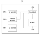
- the communication device 1700 includes a processor 1710, a memory 1720, an RF module 1730, a display module 1740, and a user interface module 1750.
- the communication device 1700 is shown for convenience of description and some modules may be omitted. In addition, the communication device 1700 may further include necessary modules. In addition, some modules in the communication device 1700 may be classified into more granular modules.
- the processor 1710 is configured to perform an operation according to an embodiment of the present invention illustrated with reference to the drawings. In detail, the detailed operation of the processor 1710 may refer to the contents described with reference to FIGS. 1 to 16.
- the memory 1720 is connected to the processor 1710 and stores an operating system, an application, program code, data, and the like.
- the RF module 1730 is connected to the processor 1710 and performs a function of converting a baseband signal into a radio signal or converting a radio signal into a baseband signal. To this end, the RF module 1730 performs analog conversion, amplification, filtering and frequency up-conversion, or a reverse process thereof.
- the display module 1740 is connected to the processor 1710 and displays various information.
- the display module 1740 may use well-known elements such as, but not limited to, a liquid crystal display (LCD), a light emitting diode (LED), and an organic light emitting diode (OLED).
- the user interface module 1750 is connected to the processor 1710 and may be configured with a combination of well-known user interfaces such as a keypad and a touch screen.
- each component or feature is to be considered optional unless stated otherwise.
- Each component or feature may be embodied in a form that is not combined with other components or features. It is also possible to combine some of the components and / or features to form an embodiment of the invention.
- the order of the operations described in the embodiments of the present invention may be changed. Some components or features of one embodiment may be included in another embodiment or may be replaced with corresponding components or features of another embodiment. It is obvious that the claims may be combined to form an embodiment by combining claims that do not have an explicit citation relationship in the claims or as new claims by post-application correction.
- Certain operations described in this document as being performed by a base station may in some cases be performed by an upper node thereof. That is, it is obvious that various operations performed for communication with the terminal in a network including a plurality of network nodes including a base station may be performed by the base station or other network nodes other than the base station.
- a base station may be replaced by terms such as a fixed station, a Node B, an eNode B (eNB), an access point, and the like.
- Embodiments according to the present invention may be implemented by various means, for example, hardware, firmware, software, or a combination thereof.
- an embodiment of the present invention may include one or more application specific integrated circuits (ASICs), digital signal processors (DSPs), digital signal processing devices (DSPDs), programmable logic devices (PLDs), FPGAs ( field programmable gate arrays), processors, controllers, microcontrollers, microprocessors, and the like.
- ASICs application specific integrated circuits
- DSPs digital signal processors
- DSPDs digital signal processing devices
- PLDs programmable logic devices
- FPGAs field programmable gate arrays
- processors controllers, microcontrollers, microprocessors, and the like.
- an embodiment of the present invention may be implemented in the form of a module, procedure, function, etc. that performs the functions or operations described above.
- the software code may be stored in a memory unit and driven by a processor.
- the memory unit may be located inside or outside the processor, and may exchange data with the processor by various known means.
- next generation wireless communication system as described above, a method for transmitting and receiving a signal through a sidelink and an apparatus therefor have been described with reference to an example applied to a 3GPP LTE system.
- the present invention may be applied to various wireless communication systems in addition to the 3GPP LTE system.
Abstract
본 출원에서는 무선 통신 시스템에서 단말이 복수의 심볼들로 구성되는 서브프레임을 통하여 사이드링크 신호를 송수신하는 방법이 개시된다. 구체적으로, 상기 방법은, 상기 서브프레임 상의 미리 결정된 제 1 심볼 상에서, 사이드링크 데이터 신호를 위한 심볼 정보를 포함하는 제 1 사이드링크 제어 신호를 수신하는 단계; 상기 서브프레임 상에서 상기 제 1 사이드링크 제어 신호에 따라 상기 사이드링크 데이터 신호를 수신하는 단계; 및 상기 서브프레임의 제 2 심볼 상에서, 상기 사이드링크 데이터 신호에 대한 응답 정보를 포함하는 제 2 사이드링크 제어 신호를 송신하는 단계를 포함하고, 상기 제 1 심볼은 상기 서브프레임 상에 하향링크 제어 신호를 위하여 유보된 심볼이 최대 개수만큼 존재한다는 가정 하에 결정되고, 상기 제 2 심볼은 상기 서브프레임 상에 상향링크 제어 신호를 위하여 유보된 심볼의 직전 심볼인 것을 특징으로 한다.
Description
본 발명은 차세대 무선 통신 시스템에 관한 것으로서, 보다 상세하게는, 차세대 무선 통신 시스템에서 사이드링크를 통한 신호 송수신 방법 및 이를 위한 장치에 관한 것이다.
본 발명이 적용될 수 있는 무선 통신 시스템의 일례로서 3GPP LTE (3rd Generation Partnership Project Long Term Evolution; 이하 "LTE"라 함) 통신 시스템에 대해 개략적으로 설명한다.
도 1은 무선 통신 시스템의 일례로서 E-UMTS 망구조를 개략적으로 도시한 도면이다. E-UMTS(Evolved Universal Mobile Telecommunications System) 시스템은 기존 UMTS(Universal Mobile Telecommunications System)에서 진화한 시스템으로서, 현재 3GPP에서 기초적인 표준화 작업을 진행하고 있다. 일반적으로 E-UMTS는 LTE(Long Term Evolution) 시스템이라고 할 수도 있다. UMTS 및 E-UMTS의 기술 규격(technical specification)의 상세한 내용은 각각 "3rd Generation Partnership Project; Technical Specification Group Radio Access Network"의 Release 7과 Release 8을 참조할 수 있다.
도 1을 참조하면, E-UMTS는 단말(User Equipment; UE)과 기지국(eNode B; eNB, 네트워크(E-UTRAN)의 종단에 위치하여 외부 네트워크와 연결되는 접속 게이트웨이(Access Gateway; AG)를 포함한다. 기지국은 브로드캐스트 서비스, 멀티캐스트 서비스 및/또는 유니캐스트 서비스를 위해 다중 데이터 스트림을 동시에 송신할 수 있다.
한 기지국에는 하나 이상의 셀이 존재한다. 셀은 1.25, 2.5, 5, 10, 15, 20Mhz 등의 대역폭 중 하나로 설정돼 여러 단말에게 하향 또는 상향 송신 서비스를 제공한다. 서로 다른 셀은 서로 다른 대역폭을 제공하도록 설정될 수 있다. 기지국은 다수의 단말에 대한 데이터 송수신을 제어한다. 하향링크(Downlink; DL) 데이터에 대해 기지국은 하향링크 스케줄링 정보를 송신하여 해당 단말에게 데이터가 송신될 시간/주파수 영역, 부호화, 데이터 크기, HARQ(Hybrid Automatic Repeat and reQuest) 관련 정보 등을 알려준다. 또한, 상향링크(Uplink; UL) 데이터에 대해 기지국은 상향링크 스케줄링 정보를 해당 단말에게 송신하여 해당 단말이 사용할 수 있는 시간/주파수 영역, 부호화, 데이터 크기, HARQ 관련 정보 등을 알려준다. 기지국간에는 사용자 트래픽 또는 제어 트래픽 송신을 위한 인터페이스가 사용될 수 있다. 핵심망(Core Network; CN)은 AG와 단말의 사용자 등록 등을 위한 네트워크 노드 등으로 구성될 수 있다. AG는 복수의 셀들로 구성되는 TA(Tracking Area) 단위로 단말의 이동성을 관리한다.
무선 통신 기술은 WCDMA를 기반으로 LTE까지 개발되어 왔지만, 사용자와 사업자의 요구와 기대는 지속적으로 증가하고 있다. 또한, 다른 무선 접속 기술이 계속 개발되고 있으므로 향후 경쟁력을 가지기 위해서는 새로운 기술 진화가 요구된다. 비트당 비용 감소, 서비스 가용성 증대, 융통성 있는 주파수 밴드의 사용, 단순구조와 개방형 인터페이스, 단말의 적절한 파워 소모 등이 요구된다.
상술한 바와 같은 논의를 바탕으로 이하에서는 차세대 무선 통신 시스템에서 사이드링크를 통한 신호 송수신 방법 및 이를 위한 장치를 제안하고자 한다.
본 발명의 일 실시예인 무선 통신 시스템에서 단말이 복수의 심볼들로 구성되는 서브프레임을 통하여 사이드링크 신호를 송수신하는 방법은, 상기 서브프레임 상의 미리 결정된 제 1 심볼 상에서, 사이드링크 데이터 신호를 위한 심볼 정보를 포함하는 제 1 사이드링크 제어 신호를 수신하는 단계; 상기 서브프레임 상에서 상기 제 1 사이드링크 제어 신호에 따라 상기 사이드링크 데이터 신호를 수신하는 단계; 및 상기 서브프레임의 제 2 심볼 상에서, 상기 사이드링크 데이터 신호에 대한 응답 정보를 포함하는 제 2 사이드링크 제어 신호를 송신하는 단계를 포함한다.
한편, 본 발명의 일 실시예인 무선 통신 시스템에서의 단말은, 무선 통신 모듈; 및 상기 무선 통신 모듈과 연결된 프로세서를 포함하고, 상기 프로세서는 상기 서브프레임 상의 미리 결정된 제 1 심볼 상에서 사이드링크 데이터 신호를 위한 심볼 정보를 포함하는 제 1 사이드링크 제어 신호를 수신하고, 상기 서브프레임 상에서 상기 제 1 사이드링크 제어 신호에 따라 상기 사이드링크 데이터 신호를 수신하며, 상기 서브프레임의 제 2 심볼 상에서, 상기 사이드링크 데이터 신호에 대한 응답 정보를 포함하는 제 2 사이드링크 제어 신호를 송신한다.
바람직하게는, 상기 제 1 심볼은 상기 서브프레임 상에 하향링크 제어 신호를 위하여 유보된 심볼이 최대 개수만큼 존재한다는 가정 하에 결정되고, 상기 제 2 심볼은 상기 서브프레임 상에 상향링크 제어 신호를 위하여 유보된 심볼의 직전 심볼인 것을 특징으로 한다.
구체적으로, 상기 제 1 심볼은 상기 복수의 심볼들 중, 상기 하향링크 제어 신호를 위하여 유보된 심볼과 타이밍 어드밴스 적용을 위하여 가드 구간으로 유보된 하나의 심볼 다음에 정의되는 심볼일 수 있다. 이 경우 상기 하향링크 제어 신호를 위하여 유보된 심볼의 개수에 관한 정보는 상위 계층을 통하여 기지국으로부터 수신될 수 있다.
추가적으로, 상기 사이드링크 데이터 신호를 수신하기 이전에 상기 서브프레임 상의 특정 심볼을 통하여 제 3 사이드링크 제어 신호가 송신될 수 있다. 특히, 상기 제 3 사이드링크 제어 신호는 상기 서브프레임 이전의 다른 서브프레임에서 수신한 사이드링크 데이터 신호에 대한 응답 정보를 포함하는 것을 특징으로 한다.
보다 바람직하게는, 상기 하향링크 제어 신호를 위하여 유보된 심볼은 상기 서브프레임의 첫 번째 심볼부터 유보되며, 상기 상향링크 제어 신호를 위하여 유보된 심볼은 상기 서브프레임 상의 마지막 심볼인 것을 특징으로 한다.
본 발명의 실시예에 따르면 차세대 무선 통신 시스템에서 사이드링크 신호를 보다 효율적으로 송수신할 수 있다.
본 발명에서 얻을 수 있는 효과는 이상에서 언급한 효과들로 제한되지 않으며, 언급하지 않은 또 다른 효과들은 아래의 기재로부터 본 발명이 속하는 기술분야에서 통상의 지식을 가진 자에게 명확하게 이해될 수 있을 것이다.
도 1은 무선 통신 시스템의 일례로서 E-UMTS 망구조를 개략적으로 도시한 도면.
도 2는 3GPP 무선 접속망 규격을 기반으로 한 단말과 E-UTRAN 사이의 무선 인터페이스 프로토콜(Radio Interface Protocol)의 제어평면(Control Plane) 및 사용자평면(User Plane) 구조를 나타내는 도면.
도 3은 3GPP 시스템에 이용되는 물리 채널들 및 이들을 이용한 일반적인 신호 송신 방법을 설명하기 위한 도면.
도 4는 LTE 시스템에서 사용되는 무선 프레임의 구조를 예시하는 도면.
도 5는 LTE 시스템에서 사용되는 하향링크 무선 프레임의 구조를 예시하는 도면.
도 6은 LTE 시스템에서 사용되는 상향링크 서브프레임의 구조를 도시하는 도면.
도 7은 TXRU와 안테나 엘리먼트의 연결 방식의 일례들을 나타낸다.
도 8은 Self-contained 서브프레임 구조의 일 예이다.
도 9는 self-contained 서브프레임에 대하여 구체적인 설정예를 도시한다.
도 10은 단말 간 직접 통신의 개념도이다.
도 11은 본 발명의 실시에에 따른 사이드링크 자원 설정의 일 예이다.
도 12는 본 발명의 실시예에 따른 사이드링크 자원 설정에서 추가적인 TA (timing advance)가 적용된 예를 도시한다.
도 13은 본 발명의 실시에에 따른 사이드링크 자원 설정의 다른 예이다.
도 14는 본 발명의 실시예에 따른 사이드링크 자원 설정에서 추가적인 TA가 적용된 다른 예를 도시한다.
도 15는 본 발명의 실시에에 따라 사이드링크 데이터 전송에 대한 HARQ-ACK 자원이 구성된 사이드링크 자원 설정의 예이다.
도 16은 본 발명의 실시에에 따라 사이드링크 데이터 전송에 대한 HARQ-ACK 자원이 구성된 사이드링크 자원 설정의 다른 예이다.
도 17은 본 발명의 일 실시예에 따른 통신 장치의 블록 구성도를 예시한다.
이하에서 첨부된 도면을 참조하여 설명된 본 발명의 실시예들에 의해 본 발명의 구성, 작용 및 다른 특징들이 용이하게 이해될 수 있을 것이다. 이하에서 설명되는 실시예들은 본 발명의 기술적 특징들이 3GPP 시스템에 적용된 예들이다.
본 명세서는 LTE 시스템 및 LTE-A 시스템을 사용하여 본 발명의 실시예를 설명하지만, 이는 예시로서 본 발명의 실시예는 상기 정의에 해당되는 어떤 통신 시스템에도 적용될 수 있다.
또한, 본 명세서는 기지국의 명칭은 RRH(remote radio head), eNB, TP(transmission point), RP(reception point), 중계기(relay) 등을 포함하는 포괄적인 용어로 사용될 수 있다.
도 2는 3GPP 무선 접속망 규격을 기반으로 한 단말과 E-UTRAN 사이의 무선 인터페이스 프로토콜(Radio Interface Protocol)의 제어평면(Control Plane) 및 사용자평면(User Plane) 구조를 나타내는 도면이다. 제어평면은 단말(User Equipment; UE)과 네트워크가 호를 관리하기 위해서 이용하는 제어 메시지들이 송신되는 통로를 의미한다. 사용자평면은 애플리케이션 계층에서 생성된 데이터, 예를 들어, 음성 데이터 또는 인터넷 패킷 데이터 등이 송신되는 통로를 의미한다.
제1계층인 물리계층은 물리채널(Physical Channel)을 이용하여 상위 계층에게 정보 송신 서비스(Information Transfer Service)를 제공한다. 물리계층은 상위에 있는 매체접속제어(Medium Access Control) 계층과는 송신채널(Trans포트 Channel)을 통해 연결되어 있다. 상기 송신채널을 통해 매체접속제어 계층과 물리계층 사이에 데이터가 이동한다. 송신측과 수신측의 물리계층 사이는 물리채널을 통해 데이터가 이동한다. 상기 물리채널은 시간과 주파수를 무선 자원으로 활용한다. 구체적으로, 물리채널은 하향링크에서 OFDMA(Orthogonal Frequency Division Multiple Access) 방식으로 변조되고, 상향링크에서 SC-FDMA(Single Carrier Frequency Division Multiple Access) 방식으로 변조된다.
제2계층의 매체접속제어(Medium Access Control; MAC) 계층은 논리채널(Logical Channel)을 통해 상위계층인 무선링크제어(Radio Link Control; RLC) 계층에 서비스를 제공한다. 제2계층의 RLC 계층은 신뢰성 있는 데이터 송신을 지원한다. RLC 계층의 기능은 MAC 내부의 기능 블록으로 구현될 수도 있다. 제2계층의 PDCP(Packet Data Convergence Protocol) 계층은 대역폭이 좁은 무선 인터페이스에서 IPv4나 IPv6와 같은 IP 패킷을 효율적으로 송신하기 위해 불필요한 제어정보를 줄여주는 헤더 압축(Header Compression) 기능을 수행한다.
제3계층의 최하부에 위치한 무선 자원제어(Radio Resource Control; RRC) 계층은 제어평면에서만 정의된다. RRC 계층은 무선베어러(Radio Bearer; RB)들의 설정(Configuration), 재설정(Re-configuration) 및 해제(Release)와 관련되어 논리채널, 송신채널 및 물리채널들의 제어를 담당한다. RB는 단말과 네트워크 간의 데이터 전달을 위해 제2계층에 의해 제공되는 서비스를 의미한다. 이를 위해, 단말과 네트워크의 RRC 계층은 서로 RRC 메시지를 교환한다. 단말과 네트워크의 RRC 계층 사이에 RRC 연결(RRC Connected)이 있을 경우, 단말은 RRC 연결 상태(Connected Mode)에 있게 되고, 그렇지 못할 경우 RRC 휴지 상태(Idle Mode)에 있게 된다. RRC 계층의 상위에 있는 NAS(Non-Access Stratum) 계층은 세션 관리(Session Management)와 이동성 관리(Mobility Management) 등의 기능을 수행한다.
네트워크에서 단말로 데이터를 송신하는 하향 송신채널은 시스템 정보를 송신하는 BCH(Broadcast Channel), 페이징 메시지를 송신하는 PCH(Paging Channel), 사용자 트래픽이나 제어 메시지를 송신하는 하향 SCH(Shared Channel) 등이 있다. 하향 멀티캐스트 또는 방송 서비스의 트래픽 또는 제어 메시지의 경우 하향 SCH를 통해 송신될 수도 있고, 또는 별도의 하향 MCH(Multicast Channel)을 통해 송신될 수도 있다. 한편, 단말에서 네트워크로 데이터를 송신하는 상향 송신채널로는 초기 제어 메시지를 송신하는 RACH(Random Access Channel), 사용자 트래픽이나 제어 메시지를 송신하는 상향 SCH(Shared Channel)가 있다. 송신채널의 상위에 있으며, 송신채널에 매핑되는 논리채널(Logical Channel)로는 BCCH(Broadcast Control Channel), PCCH(Paging Control Channel), CCCH(Common Control Channel), MCCH(Multicast Control Channel), MTCH(Multicast Traffic Channel) 등이 있다.
도 3은 3GPP 시스템에 이용되는 물리 채널들 및 이들을 이용한 일반적인 신호 송신 방법을 설명하기 위한 도면이다.
단말은 전원이 켜지거나 새로이 셀에 진입한 경우 기지국과 동기를 맞추는 등의 초기 셀 탐색(Initial cell search) 작업을 수행한다(S301). 이를 위해, 단말은 기지국으로부터 주 동기 채널(Primary Synchronization Channel; P-SCH) 및 부 동기 채널(Secondary Synchronization Channel; S-SCH)을 수신하여 기지국과 동기를 맞추고, 셀 ID 등의 정보를 획득할 수 있다. 그 후, 단말은 기지국으로부터 물리 방송 채널(Physical Broadcast Channel)를 수신하여 셀 내 방송 정보를 획득할 수 있다. 한편, 단말은 초기 셀 탐색 단계에서 하향링크 참조 신호(Downlink Reference Signal; DL RS)를 수신하여 하향링크 채널 상태를 확인할 수 있다.
초기 셀 탐색을 마친 단말은 물리 하향링크 제어 채널(Physical Downlink Control Channel; PDCCH) 및 상기 PDCCH에 실린 정보에 따라 물리 하향링크 공유 채널(Physical Downlink Control Channel; PDSCH)을 수신함으로써 좀더 구체적인 시스템 정보를 획득할 수 있다(S302).
한편, 기지국에 최초로 접속하거나 신호 송신을 위한 무선 자원이 없는 경우 단말은 기지국에 대해 임의 접속 과정(Random Access Procedure; RACH)을 수행할 수 있다(단계 S303 내지 단계 S306). 이를 위해, 단말은 물리 임의 접속 채널(Physical Random Access Channel; PRACH)을 통해 특정 시퀀스를 프리앰블로 송신하고(S303 및 S305), PDCCH 및 대응하는 PDSCH를 통해 프리앰블에 대한 응답 메시지를 수신할 수 있다(S304 및 S306). 경쟁 기반 RACH의 경우, 추가적으로 충돌 해결 절차(Contention Resolution Procedure)를 수행할 수 있다.
상술한 바와 같은 절차를 수행한 단말은 이후 일반적인 상/하향링크 신호 송신 절차로서 PDCCH/PDSCH 수신(S307) 및 물리 상향링크 공유 채널(Physical Uplink Shared Channel; PUSCH)/물리 상향링크 제어 채널(Physical Uplink Control Channel; PUCCH) 송신(S308)을 수행할 수 있다. 특히 단말은 PDCCH를 통하여 하향링크 제어 정보(Downlink Control Information; DCI)를 수신한다. 여기서 DCI는 단말에 대한 자원 할당 정보와 같은 제어 정보를 포함하며, 그 사용 목적에 따라 포맷이 서로 다르다.
한편, 단말이 상향링크를 통해 기지국에 송신하는 또는 단말이 기지국으로부터 수신하는 제어 정보는 하향링크/상향링크 ACK/NACK 신호, CQI(Channel Quality Indicator), PMI(Precoding Matrix 인덱스), RI(Rank Indicator) 등을 포함한다. 3GPP LTE 시스템의 경우, 단말은 상술한 CQI/PMI/RI 등의 제어 정보를 PUSCH 및/또는 PUCCH를 통해 송신할 수 있다.
도 4는 LTE 시스템에서 사용되는 무선 프레임의 구조를 예시하는 도면이다.
도 4를 참조하면, 무선 프레임(radio frame)은 10ms(327200×Ts)의 길이를 가지며 10개의 균등한 크기의 서브프레임(subframe)으로 구성되어 있다. 각각의 서브프레임은 1ms의 길이를 가지며 2개의 슬롯(slot)으로 구성되어 있다. 각각의 슬롯은 0.5ms(15360×Ts)의 길이를 가진다. 여기에서, Ts는 샘플링 시간을 나타내고, Ts=1/(15kHz×2048)=3.2552×10-8(약 33ns)로 표시된다. 슬롯은 시간 영역에서 복수의 OFDM 심볼을 포함하고, 주파수 영역에서 복수의 자원블록(Resource Block; RB)을 포함한다. LTE 시스템에서 하나의 자원블록은 12개의 부반송파×7(6)개의 OFDM 심볼을 포함한다. 데이터가 송신되는 단위시간인 TTI(Transmission Time Interval)는 하나 이상의 서브프레임 단위로 정해질 수 있다. 상술한 무선 프레임의 구조는 예시에 불과하고, 무선 프레임에 포함되는 서브프레임의 수 또는 서브프레임에 포함되는 슬롯의 수, 슬롯에 포함되는 OFDM 심볼의 수는 다양하게 변경될 수 있다.
도 5는 하향링크 무선 프레임에서 하나의 서브프레임의 제어 영역에 포함되는 제어 채널을 예시하는 도면이다.
도 5를 참조하면, 서브프레임은 14개의 OFDM 심볼로 구성되어 있다. 서브프레임 설정에 따라 처음 1 내지 3개의 OFDM 심볼은 제어 영역으로 사용되고 나머지 13~11개의 OFDM 심볼은 데이터 영역으로 사용된다. 도면에서 R1 내지 R4는 안테나 0 내지 3에 대한 기준 신호(Reference Signal(RS) 또는 Pilot Signal)를 나타낸다. RS는 제어 영역 및 데이터 영역과 상관없이 서브프레임 내에 일정한 패턴으로 고정된다. 제어 채널은 제어 영역 중에서 RS가 할당되지 않은 자원에 할당되고, 트래픽 채널도 데이터 영역 중에서 RS가 할당되지 않은 자원에 할당된다. 제어 영역에 할당되는 제어 채널로는 PCFICH(Physical Control Format Indicator CHannel), PHICH(Physical Hybrid-ARQ Indicator CHannel), PDCCH(Physical Downlink Control CHannel) 등이 있다.
PCFICH는 물리 제어 포맷 지시자 채널로서 매 서브프레임 마다 PDCCH에 사용되는 OFDM 심볼의 개수를 단말에게 알려준다. PCFICH는 첫 번째 OFDM 심볼에 위치하며 PHICH 및 PDCCH에 우선하여 설정된다. PCFICH는 4개의 REG(Resource Element Group)로 구성되고, 각각의 REG는 셀 ID(Cell IDentity)에 기초하여 제어 영역 내에 분산된다. 하나의 REG는 4개의 RE(Resource Element)로 구성된다. RE는 하나의 부반송파×하나의 OFDM 심볼로 정의되는 최소 물리 자원을 나타낸다. PCFICH 값은 대역폭에 따라 1 내지 3 또는 2 내지 4의 값을 지시하며 QPSK(Quadrature Phase Shift Keying)로 변조된다.
PHICH는 물리 HARQ(Hybrid - Automatic Repeat and request) 지시자 채널로서 상향링크 송신에 대한 HARQ ACK/NACK을 나르는데 사용된다. 즉, PHICH는 UL HARQ를 위한 DL ACK/NACK 정보가 송신되는 채널을 나타낸다. PHICH는 1개의 REG로 구성되고, 셀 특정(cell-specific)하게 스크램블(scrambling) 된다. ACK/NACK은 1 비트로 지시되며, BPSK(Binary phase shift keying)로 변조된다. 변조된 ACK/NACK은 확산인자(Spreading Factor; SF) = 2 또는 4로 확산된다. 동일한 자원에 매핑되는 복수의 PHICH는 PHICH 그룹을 구성한다. PHICH 그룹에 다중화되는 PHICH의 개수는 확산 코드의 개수에 따라 결정된다. PHICH (그룹)은 주파수 영역 및/또는 시간 영역에서 다이버시티 이득을 얻기 위해 3번 반복(repetition)된다.
PDCCH는 물리 하향링크 제어 채널로서 서브프레임의 처음 n개의 OFDM 심볼에 할당된다. 여기에서, n은 1 이상의 정수로서 PCFICH에 의해 지시된다. PDCCH는 하나 이상의 CCE로 구성된다. PDCCH는 송신 채널인 PCH(Paging channel) 및 DL-SCH(Downlink-shared channel)의 자원할당과 관련된 정보, 상향링크 스케줄링 그랜트(Uplink Scheduling Grant), HARQ 정보 등을 각 단말 또는 단말 그룹에게 알려준다. PCH(Paging channel) 및 DL-SCH(Downlink-shared channel)는 PDSCH를 통해 송신된다. 따라서, 기지국과 단말은 일반적으로 특정한 제어 정보 또는 특정한 서비스 데이터를 제외하고는 PDSCH를 통해서 데이터를 각각 송신 및 수신한다.
PDSCH의 데이터가 어떤 단말(하나 또는 복수의 단말)에게 송신되는 것이며, 상기 단말들이 어떻게 PDSCH 데이터를 수신하고 디코딩(decoding)을 해야 하는 지에 대한 정보 등은 PDCCH에 포함되어 송신된다. 예를 들어, 특정 PDCCH가 "A"라는 RNTI(Radio Network Temporary Identity)로 CRC 마스킹(masking)되어 있고, "B"라는 무선자원(예, 주파수 위치) 및 "C"라는 DCI 포맷 즉, 송신 형식 정보(예, 송신 블록 사이즈, 변조 방식, 코딩 정보 등)를 이용해 송신되는 데이터에 관한 정보가 특정 서브프레임을 통해 송신된다고 가정한다. 이 경우, 셀 내의 단말은 자신이 가지고 있는 RNTI 정보를 이용하여 검색 영역에서 PDCCH를 모니터링, 즉 블라인드 디코딩하고, "A" RNTI를 가지고 있는 하나 이상의 단말이 있다면, 상기 단말들은 PDCCH를 수신하고, 수신한 PDCCH의 정보를 통해 "B"와 "C"에 의해 지시되는 PDSCH를 수신한다.
도 6은 LTE 시스템에서 사용되는 상향링크 서브프레임의 구조를 도시하는 도면이다.
도 6을 참조하면, 상향링크 서브프레임은 제어정보를 나르는 PUCCH(Physical Uplink Control CHannel)가 할당되는 영역과 사용자 데이터를 나르는 PUSCH(Physical Uplink Shared CHannel)가 할당되는 영역으로 나눌 수 있다. 서브프레임의 중간 부분이 PUSCH에 할당되고, 주파수 영역에서 데이터 영역의 양측 부분이 PUCCH에 할당된다. PUCCH 상에 송신되는 제어정보는 HARQ에 사용되는 ACK/NACK, 하향링크 채널 상태를 나타내는 CQI(Channel Quality Indicator), MIMO를 위한 RI(Rank Indicator), 상향링크 자원 할당 요청인 SR(Scheduling Request) 등이 있다. 한 단말에 대한 PUCCH는 서브프레임 내의 각 슬롯에서 서로 다른 주파수를 차지하는 하나의 자원블록을 사용한다. 즉, PUCCH에 할당되는 2개의 자원블록은 슬롯 경계에서 주파수 호핑(frequency hopping)된다. 특히 도 6은 m=0인 PUCCH, m=1인 PUCCH, m=2인 PUCCH, m=3인 PUCCH가 서브프레임에 할당되는 것을 예시한다.
이하, 채널 상태 정보(channel state information, CSI) 보고에 관하여 설명한다. 현재 LTE 표준에서는 채널 상태 정보 없이 운용되는 개루프(open-loop) MIMO와 채널 상태 정보에 기반하여 운용되는 폐루프(closed-loop) MIMO 두 가지 송신 방식이 존재한다. 특히, 폐루프 MIMO 에서는 MIMO 안테나의 다중화 이득(다중화 gain)을 얻기 위해 기지국 및 단말 각각은 채널 상태 정보를 바탕으로 빔포밍을 수행할 수 있다. 기지국은 채널 상태 정보를 단말로부터 얻기 위해, 단말에게 PUCCH(Physical Uplink Control CHannel) 또는 PUSCH(Physical Uplink Shared CHannel)를 할당하여 하향링크 신호에 대한채널 상태 정보(CSI)를 피드백 하도록 명령한다.
CSI는 RI(Rank Indicator), PMI(Precoding Matrix 인덱스), CQI(Channel Quality Indication) 세가지 정보로 크게 분류된다. 우선, RI는 상술한 바와 같이 채널의 랭크 정보를 나타내며, 단말이 동일 주파수-시간 자원을 통해 수신할 수 있는 스트림의 개수를 의미한다. 또한, RI는 채널의 롱텀 페이딩(long term fading)에 의해 결정되므로 PMI, CQI 값 보다 통상 더 긴 주기로 기지국으로 피드백 된다.
두 번째로, PMI는 채널의 공간 특성을 반영한 값으로 SINR 등의 메트릭(metric)을 기준으로 단말이 선호하는 기지국의 프리코딩 행렬 인덱스를 나타낸다. 마지막으로, CQI는 채널의 세기를 나타내는 값으로 통상 기지국이 PMI를 이용했을 때 얻을 수 있는 수신 SINR을 의미한다.
3GPP LTE-A 시스템에서 기지국은 다수의 CSI 프로세스를 UE에게 설정하고, 각 CSI 프로세스에 대한 CSI를 보고 받을 수 있다. 여기서 CSI 프로세스는 기지국으로부터의 신호 품질 특정을 위한 CSI-RS 자원과 간섭 측정을 위한 CSI-IM (interference measurement) 자원, 즉 IMR (interference measurement resource)로 구성된다.
Millimeter Wave (mmW)에서는 파장이 짧아져서 동일 면적에 다수개의 안테나 엘리먼트의 설치가 가능하다. 구체적으로, 30GHz 대역에서 파장은 1cm로써 4 by 4 cm의 패널(panel)에 0.5 lambda(파장) 간격으로 2D (dimension) 배열 형태인 총 64(8x8)의 안테나 엘리먼트 설치가 가능하다. 그러므로 mmW 분야에서의 최근 동향에서는 다수개의 안테나 엘리먼트를 사용하여 BF (beamforming) 이득을 높여 커버리지를 증가시키거나, 쓰루풋 (throughput)의 증대를 시도하고 있다.
이 경우에 안테나 엘리먼트 별로 송신 파워 및 위상 조절이 가능하도록 TXRU (Transceiver Unit)을 구비한다면, 주파수 자원 별로 독립적인 빔포밍이 가능하다. 그러나 100여개의 안테나 엘리먼트 모두에 TXRU를 설치하기에는 가격측면에서 실효성이 떨어지는 문제를 갖게 된다. 그러므로 하나의 TXRU에 다수개의 안테나 엘리먼트를 맵핑하고 아날로그 위상 천이기 (analog phase shifter)로 빔의 방향을 조절하는 방식이 고려되고 있다. 이러한 아날로그 빔포밍 방식은 전 대역에 있어서 하나의 빔 방향만을 만들 수 있어 주파수 선택적 빔포밍을 해줄 수 없는 단점을 갖는다.
디지털 BF와 아날로그 BF의 중간 형태로 Q개의 안테나 엘리먼트보다 적은 개수인 B개의 TXRU를 갖는 hybrid BF를 고려할 수 있다. 이 경우에 B개의 TXRU와 Q개의 안테나 엘리먼트의 연결 방식에 따라서 차이는 있지만, 동시에 송신할 수 있는 빔 방향은 B개 이하로 제한되게 된다.
도 7은 TXRU와 안테나 엘리먼트의 연결 방식의 일례들을 나타낸다.
도 7의 (a)은 TXRU가 서브-어레이(sub-array)에 연결된 방식을 나타낸다. 이 경우에 안테나 엘리먼트는 하나의 TXRU에만 연결된다. 이와 달리 도 7의 (b)는 TXRU가 모든 안테나 엘리먼트에 연결된 방식을 나타낸다. 이 경우에 안테나 엘리먼트는 모든 TXRU에 연결된다. 도 7에서 W는 아날로그 위상 천이기에 의해 곱해지는 위상 벡터를 나타낸다. 즉, W에 의해 아날로그 빔포밍의 방향이 결정된다. 여기서 CSI-RS 안테나 포트와 TXRU들과의 맵핑은 1-to-1 또는 1-to-多 일 수 있다.
더욱 많은 통신 기기들이 더욱 큰 통신 용량을 요구하게 됨에 따라 기존의 RAT (radio access technology)에 비해 향상된 무선 광대역 통신에 대한 필요성이 대두되고 있다. 또한 다수의 기기 및 사물들을 연결하여 언제 어디서나 다양한 서비스를 제공하는 메시브 (massive) MTC (Machine Type Communications) 역시 차세대 통신에서 고려될 주요 이슈 중 하나이다. 뿐만 아니라 신뢰도 (reliability) 및 레이턴시 (latency)에 민감한 서비스/UE를 고려한 통신 시스템 디자인이 논의되고 있다. 이러한 점을 고려한 차세대 RAT의 도입이 논의되고 있으며, 본 발명에서는 편의상 NewRAT 이라고 지칭한다.
TDD 시스템에서 데이터 송신 레이턴시를 최소화하기 위하여 5세대 NewRAT에서는 도 8과 같은 self-contained 서브프레임 구조를 고려하고 있다. 도 8은 Self-contained 서브프레임 구조의 일 예이다.
도 8에서 빗금 영역은 하향링크 제어 영역을 나타내고, 검정색 부분은 상향링크 제어 영역을 나타낸다. 표시가 없는 영역은 하향링크 데이터 송신을 위해 사용될 수도 있고, 상향링크 데이터 송신을 위해 사용될 수도 있다. 이러한 구조의 특징은 한 개의 서브프레임 내에서 하향링크 송신과 상향링크 송신이 순차적으로 진행되어, 서브프레임 내에서 하향링크 데이터를 보내고, 상향링크 ACK/NACK도 받을 수 있다. 결과적으로 데이터 송신 에러 발생시에 데이터 재송신까지 걸리는 시간을 줄이게 되며, 이로 인해 최종 데이터 전달의 레이턴시를 최소화할 수 있다.
이러한 self-contained 서브프레임 구조에서 기지국과 UE가 송신 모드에서 수신모드로 전환 과정 또는 수신모드에서 송신모드로 전환 과정을 위한 시간 간극 (time gap)이 필요하다. 이를 위하여 self-contained 서브프레임 구조에서 하향링크에서 상향링크로 전환되는 시점의 일부 OFDM 심볼 (OFDM 심볼; OS)이 GP (guard period)로 설정되게 된다.
NewRAT을 기반으로 동작하는 시스템에서 구성/설정 가능한 상기 self-contained 서브프레임 타입의 일례로, 적어도 다음과 같은 4가지 서브프레임 타입을 고려할 수 있다
- 하향링크 제어 구간 + 하향링크 데이터 구간 + GP + 상향링크 제어 구간
- 하향링크 제어 구간 + 하향링크 데이터 구간
- 하향링크 제어 구간 + GP + 상향링크 데이터 구간 + 상향링크 제어 구간
- 하향링크 제어 구간 + GP + 상향링크 데이터 구간
도 9는 self-contained 서브프레임에 대하여 구체적인 설정예를 도시한다. 특히, 도 9에서 Dc는 하향링크 제어 채널 전송을 위한 하향링크 심볼을, Dd는 하향링크 데이터 채널 전송을 위한 하향링크 심볼을 의미한다. 또한, Uc는 상향링크 제어 채널 전송을 위한 상향링크 심볼을, Ud는 상향링크 데이터 채널 전송을 위한 상향링크 심볼을 의미하며, GP는 하향링크와 상향링크 간 가드 구간 (Guard Period)를 위한 심볼을 의미한다.
도 9를 참조하면, 설정 #0 내지 설정 #8까지 총 9개의 self-contained 서브프레임 설정을 예시하고 있으며, 특히 CSI-RS는 단말 측에서 CSI를 측정하기 위한 참조 신호 수신 심볼을, SRS는 단말 측에서 사운딩 참조 신호 송신을 위한 심볼을 의미한다.
도 10은 단말 간 직접 통신의 개념도이다.
도 10을 참조하면, UE가 다른 UE와 직접 무선 통신을 수행하는 D2D(device-to-device) 통신, 즉, 단말 간 직접 통신에서는 기지국이 D2D 송수신을 지시하기 위한 스케줄링 메시지를 전송할 수 있다. D2D 통신에 참여하는 UE는 기지국으로부터 D2D 스케줄링 메시지를 수신하고, D2D 스케줄링 메시지가 지시하는 송수신 동작을 수행한다. 여기서 UE는 사용자의 단말을 의미하지만 기지국과 같은 네트워크 엔티티가 UE 사이의 통신 방식에 따라서 신호를 송수신하는 경우에는 역시 일종의 UE로 간주될 수 있다. 이하에서는 UE 사이에 직접 연결된 링크를 D2D 링크로, UE가 기지국과 통신하는 링크를 NU링크로 지칭한다. 또는 UE 사이에 직접 연결된 링크를 상향링크 및 하향링크와 대비되는 개념으로 사이드링크 (Sidelink)라고 지칭할 수도 있다.
이하에서는 UE1은 일련의 자원의 집합을 의미하는 자원 풀 (resource pool) 내에서 특정한 자원에 해당하는 자원 유닛을 선택하고 해당 자원 유닛을 사용하여 D2D 신호를 전송하는 경우에 대해서 설명한다. 여기서, 자원 풀은 UE1이 기지국의 커버리지 내에 위치하는 경우 기지국이 알려줄 수 있으며, UE1이 기지국의 커버리지 밖에 있는 경우에는 다른 UE가 알려주거나 혹은 사전에 정해진 자원으로 결정될 수도 있다. 일반적으로 자원 풀은 복수의 자원 유닛으로 구성되며 각 UE는 하나 혹은 복수의 자원 유닛을 선정하여 자신의 D2D 신호 전송에 사용할 수 있다.
예를 들어, 전체 주파수 자원이 NF개로 분할되고, 전체 시간 자원이 NT개로 분할되어, 총 NF*NT 개의 자원 유닛이 정의될 수 있으며, 특히 해당 자원 풀이 NT 서브프레임을 주기로 반복된다고 할 수 있다. 특징적으로, 하나의 자원 유닛은 주기적으로 반복하여 나타날 수 있다. 혹은 시간이나 주파수 차원에서의 다이버시티 (diversity) 효과를 얻기 위하여 하나의 논리적인 자원 유닛이 맵핑되는 물리적 자원 유닛의 인덱스가 시간에 따라서 사전에 정해진 패턴으로 변화할 수도 있다. 이러한 자원 유닛 구조에 있어서, 자원 풀이란 D2D 신호를 전송하고자 하는 UE가 전송에 사용할 수 있는 자원 유닛의 집합을 의미할 수 있다.
상술한 자원 풀은 여러 종류로 세분화될 수 있다. 먼저 자원 풀에서 전송되는 사이드링크 신호의 컨텐츠에 따라서 구분될 수 있다. 일 예로 아래 1) 내지 3)과 같이 사이드링크 신호의 컨텐츠는 SA, 사이드링크 데이터 채널 및 디스커버리 신호로 구분될 수 있으며, 각각 컨텐츠에 따라서 별도의 자원 풀이 설정될 수 있다.
1) SA(Scheduling assignment): SA는 전송 UE가 후행하는 사이드링크 데이터 채널의 자원 위치 정보 및 데이터 채널의 복조를 위한 MCS(modulation and coding scheme)나 MIMO 전송 방식 등의 정보를 포함하는 신호를 지칭한다. 상기 SA는 동일 자원 유닛 상에서 사이드링크 데이터와 함께 다중화되어 전송되는 것도 가능하며, 이 경우 SA 자원 풀이란 SA가 사이드링크 데이터와 다중화되어 전송되는 자원의 풀을 의미할 수 있다.
2) 사이드링크 데이터 채널: 사이드링크 데이터 채널은 전송 UE가 사용자 데이터를 전송하는데 사용하는 채널을 지칭한다. 만약 SA가 동일 자원 유닛 상에서 사이드링크 데이터와 함께 다중화되어 전송된다면, SA 자원 풀의 특정 자원 유닛 상에서 SA 정보를 전송하는데 사용되었던 RE(resource element)를 사이드링크 데이터 채널 자원 풀에서도 사이드링크 데이터를 전송하는데 사용할 수 있다.
3) 디스커버리 신호: 전송 UE가 자신의 ID등의 정보를 전송하여 인접 UE로 하여금 자신을 발견할 수 있도록 하는 신호를 위한 자원 풀을 의미한다.
4) 동기 신호/채널(Synchronization signal/channel): 동기 신호/채널은 사이드링크 동기 신호 또는 사이드링크 방송 채널이라고도 지칭할 수 있으며, 송신 UE가 동기 신호 및 동기와 관련된 정보를 전송함으로써 수신 UE가 송신 UE에게 시간/주파수 동기를 맞추는 목적을 달성하는 신호/채널을 위한 자원 풀을 의미한다.
SA와 사이드링크 데이터는 서브프레임 상에서 분리되는 자원 풀을 사용할 수 있지만, UE가 SA와 사이드링크 데이터를 하나의 서브프레임에서 동시에 전송할 수 있는 경우라면 동일한 서브프레임에 두 종류의 자원 풀이 설정될 수도 있다.
단말이 송신을 수행한다는 점에서 상향링크와 사이드링크는 동일한 속성을 가지고 인접 셀 또는 인접 단말로의 간섭이 근본적으로 동일한 속성을 지니기 때문에, 사이드링크 전송은 상향링크로 할당된 시간 구간을 사용하는 것이 바람직하다. 하향링크와 동일한 시점에 사이드링크 전송이 발생하는 경우, 사이드링크 송신 UE와 인접해서 하향링크 수신을 수행하는 UE가 존재한다면 심각한 간섭을 받게 된다는 문제가 있다. 하지만, 적절한 간섭 제어를 수행한다면 하향링크 구간을 사이드링크로 활용하는 것이 가능하며, 이 경우에는 수신 UE 입장에서 동일한 수신 동작을 수행할 수 있다는 장점이 있다. 혹은 하향링크 구간이나 상향링크 구간과는 구분되는 별도의 구간으로 사이드링크 구간을 지정하여 동작하는 것도 가능하다.
이하에서는 상술한 바와 같이 하나의 서브프레임 내에서 하향링크와 상향링크의 부분이 공존할 수 있는 self-contained 서브프레임 구조에서 효과적으로 사이드링크 송수신 자원을 구성하는 방법을 설명한다.
<사이드링크 자원 구성 방법>
기본적으로 사이드링크의 자원을 구성하는 방법은 아래의 A-1) 내지 A-4) 중 하나를 이용할 수 있다. 특히, 아래의 설명에서 특정 심볼이 사이드링크로 사용된다는 것은 해당 심볼을 사이드링크의 데이터 송신으로 사용될 수도 있으며, 사이드링크 데이터를 스케줄링하는 사이드링크 제어 신호 (즉, SA (scheduling assignment))을 전송하는 용도 및 사이드링크 데이터에 대한 HARQ-ACK을 전송하는 용도로도 활용할 수 있다는 것을 의미할 수 있다. 따라서, 특정 심볼이 사이드링크 자원으로 설정되었다 하더라도, 해당 심볼이 다른 UE의 HARQ-ACK 전송으로 사용될 경우와 같이, 송신 UE는 해당 심볼을 자신의 데이터 전송으로 사용하지 않을 수 있다.
- 방법 A-1) 사이드링크의 자원은 하향링크 제어 신호 및/또는 상향링크 제어 신호 (SRS 포함 가능)이 항상 존재한다고 가정하고, 나머지 부분을 사용하도록 설정한다.
일 예로 도 9과 같은 서브프레임 구조에서 사이드링크는 심볼 #2에서 #11까지를 사용하도록 규정하는 것이다. 혹은 도 9의 서브프레임 설정 #2 및 서브프레임 설정 #3에서와 같이 심볼 #1이 하향링크로 사용되는 경우, 심볼 #2를 GP로 사용할 수 있도록 하고 심볼 #3부터 #11까지를 사이드링크로 사용하도록 규정할 수 있다. 혹은 심볼 #2부터 사이드링크로 사용하되 심볼 #1이 하향링크가 되는 서브프레임 설정은 기지국이 설정하지 않도록 동작할 수도 있다.
이러한 방법을 사용하는 경우 하향링크 및 상향링크 제어 신호로 활용되는 영역과의 충돌을 회피할 수 있다. 이 방법이 적용될 경우 사이드링크가 사용하는 심볼 영역은 고정되며, 적어도 한 SF 내의 심볼 개수가 변하지 않는 한 변하지 않는 것으로 규정될 수 있다.
- 방법 A-2) 사이드링크의 자원은 서브프레임 내의 모든 심볼을 사용한다고 가정하고 동작한다. 예외적으로, UE의 송신과 수신 사이의 스위칭을 위한 GP는 포함될 수 있다. 이 GP는 서브프레임의 첫 번째 심볼에 위치할 수 있으며, 이 경우는 이전 서브프레임이 도 9의 서브프레임 설정 #0, #2, #6 및 #7과 같이 마지막 심볼을 하향링크 전송 용도로 활용할 경우 최초의 사이드링크 전송 사이에 GP를 보장할 수 있다는 장점이 있다.
만일 첫 심볼부터 사이드링크 전송으로 활용한다면, 이전 서브프레임의 마지막을 하향링크로 사용하지 않도록 기지국이 적절한 서브프레임 설정을 수행해야 한다. 사이드링크가 동작할 수 있는 서브프레임은 기지국이 지정할 수 있으며, 기지국은 해당 서브프레임에서는 사이드링크 이외의 하향링크/상향링크 동작을 수행하지 않음으로써 충돌을 방지할 수 있다.
방법 A-1) 및 방법 A-2)를 사용하는 경우, 사이드링크가 점유하는 심볼의 개수가 고정이 되므로, 단말이 구현해야 하는 사이드링크 채널 구조를 단순화하여 구현 복잡도를 줄일 수 있다는 장점이 있다. 방법 A-1)은 사이드링크가 동작하는 서브프레임에서도 상향링크 제어 신호 그리고/또는 하향링크 제어 신호를 송신할 수 있다는 장점이 있는 반면, 방법 A-2)는 사이드링크가 사용하는 심볼의 개수를 최대화할 수 있다는 장점이 있다.
- 방법 A-3) 기지국이 사이드링크가 동작하는 자원을 반정적으로 조절한다.
일 예로 사이드링크 자원과 SRS 전송과의 충돌을 적절한 스케줄링으로 회피할 수 있다면 사이드링크가 심볼 #12까지를 사용하도록 규정할 수 있으며, 혹은 심볼 #13에서의 상향링크/하향링크 제어 신호와의 충돌을 회피할 수 있는 경우 심볼 #13까지를 사용하도록 규정할 수 있다. 혹은 하향링크 제어 신호와의 충돌을 회피할 수 있는 경우 심볼 #0 및 심볼 #1을 사용할 수도 있다.
기지국은 이러한 동작을 고려하여 사전에 특정 사이드링크 자원 풀에서 사용할 사이드링크 심볼 영역을 RRC시그널링과 같은 상위 계층 신호로 UE에게 알리고, UE는 이를 바탕으로 사이드링크 동작을 수행할 수 있다. 각 서브프레임마다 기지국이 설정하고자 하는 서브프레임 설정이 상이할 경우, 자원 풀에 속하는 각 서브프레임마다 사용할 사이드링크 자원을 상이하게 설정하는 것도 가능하다. 또한 동일한 자원 풀에 속하는 서브프레임이라 하더라도 기지국이 스케줄링할 상향링크 제어 신호 또는 하향링크 제어 신호에 따라서, 각 서브프레임에서 사이드링크에 사용할 심볼의 위치를 사전에 상이하게 반정적으로 지정해주는 것도 가능하다.
방법 A-1) 내지 방법 A-3)이 적용되면 기지국은 사이드링크로 동작하는 서브프레임만을 지정하면 족하고, 매 서브프레임에서 사이드링크로 사용하는 심볼 영역이 어디인지를 동적으로 지정할 필요가 없게 되어, 관련된 시그널링 오버헤드를 줄일 수 있다.
- 방법 A-4) UE가 기지국이 물리 계층 제어 신호를 통하여 동적으로 지정하는 서브프레임 구성을 파악하고 이에 맞추어 하향링크/상향링크와 충돌하지 않는 (예를 들어 상향링크 데이터 신호로 할당된) 심볼을 사용하여 사이드링크를 송수신한다.
상술한 방식들의 조합도 가능하다. 가령 사이드링크로 사용하는 구간의 시작 부분은 방법 A-4)로 동작하되 끝나는 부분은 방법 A-3)으로 동작할 수도 있다.
방법 A-4)와 같이 동작하는 경우, 송신 UE와 동일한 셀에 속한 UE는 기지국의 제어 신호를 수신하고 서브프레임 구성을 파악할 수 있을 것이다. 그러나 다른 셀에 속한 UE는 이를 수신하고 올바로 동작하기가 어렵다. 방법 A-3)을 사용하는 경우에도 기지국의 커버리지 밖에 있는 UE는 이러한 설정을 수신하기에 어려움이 따른다. 이러한 문제를 해결하기 위하여, SA는 방법 A-1)과 같이 보수적인 설정으로 전송하되, SA를 통하여 데이터 채널에서 사용하는 심볼 영역을 지정해줄 수 있다. 수신 UE는 먼저 보수적인 설정으로 SA를 검출한 다음에 획득한 정보를 토대로 데이터 채널을 수신하는 것이다.
<사이드링크 제어 채널과 데이터 채널의 배치 방법>
이하에서는 사이드링크 제어 채널 (즉, SA)과 사이드링크 데이터 채널을 배치하는 방법을 설명한다.
- 방법 B-1) SA 및 해당 SA를 통하여 스케줄링 되는 사이드링크 데이터는 동일 서브프레임에서 상이한 부반송파를 사용하여 전송되는 형태가 될 수 있다. 사이드링크 자원 구성 방법 A-4)가 적용되는 경우에는 상술한 실시예와 같이 SA와 사이드링크 데이터 채널이 맵핑되는 심볼의 집합이 상이할 수 있다.
- 방법 B-2) SA를 배치하는 다른 방법으로 사이드링크 데이터와 상이한 심볼을 사용할 수 있다. 이 방식은 수신 UE가 SA를 먼저 검출하고 이에 따라 사이드링크 데이터 채널 수신을 즉각 시도할 수 있으므로 수신 UE의 디코딩 지연 (decoding delay)를 줄일 수 있는 장점을 가진다. 세부 방식으로 아래의 방식이 가능하다.
(세부 방법 B-2-1) SA가 시작하는 지점은 하향링크 제어 신호가 나타난 직후, 혹은 하향링크 제어 신호 이후 나타나는 GP 직후에 나타난다. 이 방법은 하향링크 제어 신호와의 충돌을 회피하면서 디코딩 지연을 줄이는데 효과적이며, 상술한 사이드링크 자원 구성 방법 A-1), A-3) 및 A-4)와 결합하여 사용될 수 있다.
도 11은 본 발명의 실시에에 따른 사이드링크 자원 설정의 일 예이다. 특히, 도 11은 도 9의 서브프레임 설정 #4가 설정된 것으로 가정하며, SA, Sd, Sc는 각각 SA (scheduling assignment), 사이드링크 데이터, 사이드링크 제어 신호 (사이드링크 데이터에 대한 HARQ-ACK)을 의미한다.
도 11에서 첫 번째 서브프레임 설정은 Sd와 Sc 사이에 GP가 존재하지 않는 경우에 해당하며, 도 11에서 두 번째 서브프레임 설정은 심볼 #12가 사이드링크 데이터 송신에서 HARQ-ACK 수신으로의 전환에 필요한 GP로 사용되는 경우에 해당한다.
도 11의 첫 번째 서브프레임 설정에서, 비록 심볼 #12와 #13 사이에 명시적인 GP가 없더라도 할지라도 스위칭 시간이 존재할 수 있다. 이는 심볼 #2부터의 사이드링크 전송 타이밍을 앞당김으로써 가능하다.
도 12는 본 발명의 실시예에 따른 사이드링크 자원 설정에서 추가적인 TA (timing advance)가 적용된 예를 도시한다. 도 12를 참조하면, 한 심볼의 절반에 해당하는 추가적인 TA가 인가됨으로써 Dc와 SA 사이 및 Sd와 Sc 사이에 절반 심볼 정도의 스위칭 시간이 확보된다.
특히 이 방식은 상향링크 전송을 위한 TA를 사이드링크에 적용하지 않을 때 효과적이며, 추가적인 TA를 인가함으로써 사이드링크에 사용되는 심볼 사이에 스위칭 시간을 제공하는 원리는 다른 형태의 사이드링크 프레임 구조에도 적용이 가능하다.
(세부 방법 B-2-2) SA는 서브프레임의 첫 심볼에서 시작한다. 이 방법에 따르면 SA의 전송 자원은 하향링크 제어 신호의 전송 자원과 동일하게 구성되며 수신 UE 입장에서는 하향링크를 수신하는 것과 매우 유사한 동작이 가능하다. 본 세부 방법 B-2-2는 상술한 사이드링크 자원 구성 방법 A-2)와 결합될 수 있으며, 그 외의 사이드링크 자원 구성 방법과 결합되는 경우에는 기지국의 적절한 스케줄링이 필요하다. 만일 UE와 UE 사이의 간섭이 적절하게 조절될 수 있다면 하향링크 제어 신호와 SA가 동일 심볼에서 다른 주파수 자원을 활용하여 전송될 수도 있다. 이러한 동작을 수행할 경우, 사전에 기지국은 사이드링크 송신 UE에게 해당 서브프레임에서는 해당 UE가 수신해야 하는 하향링크 제어신호는 존재하지 않음을 알리고, 해당 UE가 하향링크 제어신호 구간을 이용하여 사이드링크 신호 전송을 수행하는 것을 허용할 수 있다.
도 13은 본 발명의 실시에에 따른 사이드링크 자원 설정의 다른 예이다. 특히, 도 13에서는 심볼 #0가 SA, 심볼 #12가 GP로 사용된 것을 알 수 있다.
도 14는 본 발명의 실시예에 따른 사이드링크 자원 설정에서 추가적인 TA가 적용된 다른 예를 도시한다. 특히, 도 14은 상술한 사이드링크 자원 구성 방법 A-2)에서 설명한 바와 같이 서브프레임의 첫 심볼을 GP로 사용하면서 SA와 Sd, Sc가 연이어 위치하는 경우에 추가적인 TA를 적용하는 경우를 도시한 것이다.
혹은, 도 13에서 예시한 설정을 사용하는 다른 방법으로 사이드링크 송신은 심볼 #0부터 별도의 추가적인 TA 없이 수행하며, 이전 서브프레임의 마지막 심볼을 GP로 설정하여 사이드링크 송수신 동작을 수행할 수 있다. 이 경우 기지국은 항상 심볼 #0부터 시작하는 사이드링크 송신 서브프레임 이전 서브프레임의 마지막 심볼을 GP로 설정하거나, 해당 심볼을 Uc로 설정하되 사이드링크 송수신에 참여하는 UE는 해당 시점에서 Uc를 전송하는 것을 회피하도록 규정될 수 있다.
<사이드링크 데이터 전송에 대한 HARQ-ACK 자원 설정>
이하에서는 사이드링크 데이터 전송에 대한 HARQ-ACK 자원을 설정하는 방법을 설명한다.
- 방법 C-1) 사이드링크에서의 HARQ-ACK은 상향링크 제어 신호와 동일한 심볼에서 전송되며 상이한 주파수 자원을 사용할 수 있다. 만일 동일 UE가 한 시점에서 하향링크 데이터 신호와 사이드링크 데이터에 대한 HARQ-ACK을 동시에 전송해야 하는 경우, 별도의 전송이 가능하다. 도 11과 도 13은 이러한 방법에 따른 것이다.
- 방법 C-2) 사이드링크에서의 HARQ-ACK은 상향링크 제어 신호가 사용하는 심볼 이전의 심볼을 사용한다.
도 15는 본 발명의 실시에에 따라 사이드링크 데이터 전송에 대한 HARQ-ACK 자원이 구성된 사이드링크 자원 설정의 예이다. 특히, 도 15의 첫번째 서브프레임 설정에서는 SA, Sd, Sc를 하나의 UE가 연속하여 전송하는 경우를 가정한 것으로, 결국 Sc는 동일 서브프레임의 Sd가 아닌 그 이전에 전송된 Sd에 대한 HARQ-ACK이 된다. 따라서 GP가 Sc와 Uc 사이에 존재하는데, 이는 Sc를 수신한 UE가 Uc의 송신으로 전환하기 위해 필요한 시간을 확보하기 위함이다.
만일 심볼 #10의 Sd와 심볼 #11의 Sc를 전송하는 UE가 상이한 경우를 지원하려면 도 15의 두 번째 서브프레임 설정을 사용할 수 있다. 이 때 심볼을 Sd ? GP ? Sc ? Uc의 순서대로 배치한 후, Sd와 Sc 사이의 GP를 활용하여 UE의 송수신 전환을 보장할 수 있게 된다. 추가적으로 도 12에서 설명한 원리를 적용하여 Sc에 추가적인 TA를 적용함으로써 Sc와 Uc 사이에 스위칭 시간이 생성되도록 동작할 수 있으며, 이를 통해 심볼 #12에서 Sc를 수신한 UE가 다시 심볼 13에서 Uc를 송신하도록 할 수 있다. 혹은 이러한 동작을 수행하지 않고 하나의 UE가 심볼 #12에서는 Sc를 수신한 다음 곧바로 심볼 13에서 Uc를 송신하는 경우를 기지국의 적절한 스케줄링을 통해 회피하도록 규정할 수 있다.
- 방법 C-3) 사이드링크에서의 HARQ-ACK은 서브프레임 앞쪽에 위치하는 심볼을 이용한다. 이는 상대적으로 수신 UE가 HARQ-ACK을 빨리 전송함으로써 송신 UE가 빨리 재전송 여부를 결정하고 다음 전송을 준비하도록 하기 위함이다.
도 16은 본 발명의 실시에에 따라 사이드링크 데이터 전송에 대한 HARQ-ACK 자원이 구성된 사이드링크 자원 설정의 다른 예이다. 특히, 도 16의 첫 번째 서브프레임 설정은 SA 이후에 HARQ-ACK이 전송되는 경우이고, 도 16의 두 번째 서브프레임 설정은 SA 이전에 HARQ-ACK이 전송되는 경우이다. 또한, 도 16의 세 번째 서브프레임 설정은 Sc와 SA 사이에 GP가 존재하는 경우이다.
한편, 도 15 또는 도 16에서는 첫 심볼이 사이드링크로 사용 가능하다고 가정하지만, 첫 일부 심볼이 하향링크로 사용되는 경우에도 사이드링크로 사용 가능한 첫 심볼에서 SA나 Sc가 위치하도록 동작할 수도 있다.
도 17은 본 발명의 일 실시예에 따른 통신 장치의 블록 구성도를 예시한다.
도 17을 참조하면, 통신 장치(1700)는 프로세서(1710), 메모리(1720), RF 모듈(1730), 디스플레이 모듈(1740) 및 사용자 인터페이스 모듈(1750)을 포함한다.
통신 장치(1700)는 설명의 편의를 위해 도시된 것으로서 일부 모듈은 생략될 수 있다. 또한, 통신 장치(1700)는 필요한 모듈을 더 포함할 수 있다. 또한, 통신 장치(1700)에서 일부 모듈은 보다 세분화된 모듈로 구분될 수 있다. 프로세서(1710)는 도면을 참조하여 예시한 본 발명의 실시 예에 따른 동작을 수행하도록 구성된다. 구체적으로, 프로세서(1710)의 자세한 동작은 도 1 내지 도 16에 기재된 내용을 참조할 수 있다.
메모리(1720)는 프로세서(1710)에 연결되며 오퍼레이팅 시스템, 어플리케이션, 프로그램 코드, 데이터 등을 저장한다. RF 모듈(1730)은 프로세서(1710)에 연결되며 기저대역 신호를 무선 신호를 변환하거나 무선신호를 기저대역 신호로 변환하는 기능을 수행한다. 이를 위해, RF 모듈(1730)은 아날로그 변환, 증폭, 필터링 및 주파수 상향 변환 또는 이들의 역과정을 수행한다. 디스플레이 모듈(1740)은 프로세서(1710)에 연결되며 다양한 정보를 디스플레이한다. 디스플레이 모듈(1740)은 이로 제한되는 것은 아니지만 LCD(Liquid Crystal Display), LED(Light Emitting Diode), OLED(Organic Light Emitting Diode)와 같은 잘 알려진 요소를 사용할 수 있다. 사용자 인터페이스 모듈(1750)은 프로세서(1710)와 연결되며 키패드, 터치 스크린 등과 같은 잘 알려진 사용자 인터페이스의 조합으로 구성될 수 있다.
이상에서 설명된 실시예들은 본 발명의 구성요소들과 특징들이 소정 형태로 결합된 것들이다. 각 구성요소 또는 특징은 별도의 명시적 언급이 없는 한 선택적인 것으로 고려되어야 한다. 각 구성요소 또는 특징은 다른 구성요소나 특징과 결합되지 않은 형태로 실시될 수 있다. 또한, 일부 구성요소들 및/또는 특징들을 결합하여 본 발명의 실시예를 구성하는 것도 가능하다. 본 발명의 실시예들에서 설명되는 동작들의 순서는 변경될 수 있다. 어느 실시예의 일부 구성이나 특징은 다른 실시예에 포함될 수 있고, 또는 다른 실시예의 대응하는 구성 또는 특징과 교체될 수 있다. 특허청구범위에서 명시적인 인용 관계가 있지 않은 청구항들을 결합하여 실시예를 구성하거나 출원 후의 보정에 의해 새로운 청구항으로 포함시킬 수 있음은 자명하다.
본 문서에서 기지국에 의해 수행된다고 설명된 특정 동작은 경우에 따라서는 그 상위 노드(upper node)에 의해 수행될 수 있다. 즉, 기지국을 포함하는 복수의 네트워크 노드들(network nodes)로 이루어지는 네트워크에서 단말과의 통신을 위해 수행되는 다양한 동작들은 기지국 또는 기지국 이외의 다른 네트워크 노드들에 의해 수행될 수 있음은 자명하다. 기지국은 고정국(fixed station), Node B, eNode B(eNB), 억세스 포인트(access point) 등의 용어에 의해 대체될 수 있다.
본 발명에 따른 실시예는 다양한 수단, 예를 들어, 하드웨어, 펌웨어(firmware), 소프트웨어 또는 그것들의 결합 등에 의해 구현될 수 있다. 하드웨어에 의한 구현의 경우, 본 발명의 일 실시예는 하나 또는 그 이상의 ASICs(application specific integrated circuits), DSPs(digital signal processors), DSPDs(digital signal processing devices), PLDs(programmable logic devices), FPGAs(field programmable gate arrays), 프로세서, 콘트롤러, 마이크로 콘트롤러, 마이크로 프로세서 등에 의해 구현될 수 있다.
펌웨어나 소프트웨어에 의한 구현의 경우, 본 발명의 일 실시예는 이상에서 설명된 기능 또는 동작들을 수행하는 모듈, 절차, 함수 등의 형태로 구현될 수 있다. 소프트웨어 코드는 메모리 유닛에 저장되어 프로세서에 의해 구동될 수 있다. 상기 메모리 유닛은 상기 프로세서 내부 또는 외부에 위치하여, 이미 공지된 다양한 수단에 의해 상기 프로세서와 데이터를 주고 받을 수 있다.
본 발명은 본 발명의 특징을 벗어나지 않는 범위에서 다른 특정한 형태로 구체화될 수 있음은 당업자에게 자명하다. 따라서, 상기의 상세한 설명은 모든 면에서 제한적으로 해석되어서는 아니되고 예시적인 것으로 고려되어야 한다. 본 발명의 범위는 첨부된 청구항의 합리적 해석에 의해 결정되어야 하고, 본 발명의 등가적 범위 내에서의 모든 변경은 본 발명의 범위에 포함된다.
상술한 바와 같은 차세대 무선 통신 시스템에서 사이드링크를 통한 신호 송수신 방법 및 이를 위한 장치는 3GPP LTE 시스템에 적용되는 예를 중심으로 설명하였으나, 3GPP LTE 시스템 이외에도 다양한 무선 통신 시스템에 적용하는 것이 가능하다.
Claims (12)
- 무선 통신 시스템에서 단말이 복수의 심볼들로 구성되는 서브프레임을 통하여 사이드링크 신호를 송수신하는 방법에 있어서,상기 서브프레임 상의 미리 결정된 제 1 심볼 상에서, 사이드링크 데이터 신호를 위한 심볼 정보를 포함하는 제 1 사이드링크 제어 신호를 수신하는 단계;상기 서브프레임 상에서 상기 제 1 사이드링크 제어 신호에 따라 상기 사이드링크 데이터 신호를 수신하는 단계; 및상기 서브프레임의 제 2 심볼 상에서, 상기 사이드링크 데이터 신호에 대한 응답 정보를 포함하는 제 2 사이드링크 제어 신호를 송신하는 단계를 포함하고,상기 제 1 심볼은 상기 서브프레임 상에 하향링크 제어 신호를 위하여 유보된 심볼이 최대 개수만큼 존재한다는 가정 하에 결정되고,상기 제 2 심볼은 상기 서브프레임 상에 상향링크 제어 신호를 위하여 유보된 심볼의 직전 심볼인 것을 특징으로 하는,사이드링크 신호 송수신 방법.
- 제 1 항에 있어서,상기 제 1 심볼은,상기 복수의 심볼들 중, 상기 하향링크 제어 신호를 위하여 유보된 심볼과 타이밍 어드밴스 적용을 위하여 가드 구간으로 유보된 하나의 심볼 다음에 정의되는 심볼인 것을 특징으로 하는,사이드링크 신호 송수신 방법.
- 제 2 항에 있어서,상기 하향링크 제어 신호를 위하여 유보된 심볼의 개수에 관한 정보는 상위 계층을 통하여 기지국으로부터 수신하는 것을 특징으로 하는,사이드링크 신호 송수신 방법.
- 제 1 항에 있어서,상기 사이드링크 데이터 신호를 수신하기 이전에, 상기 서브프레임 상의 특정 심볼을 통하여 제 3 사이드링크 제어 신호를 송신하는 단계를 포함하고,상기 제 3 사이드링크 제어 신호는,상기 서브프레임 이전의 다른 서브프레임에서 수신한 사이드링크 데이터 신호에 대한 응답 정보를 포함하는 것을 특징으로 하는,사이드링크 신호 송수신 방법.
- 제 1 항에 있어서,상기 하향링크 제어 신호를 위하여 유보된 심볼은,상기 서브프레임의 첫 번째 심볼부터 유보되는 것을 특징으로 하는,사이드링크 신호 송수신 방법.
- 제 1 항에 있어서,상기 상향링크 제어 신호를 위하여 유보된 심볼은,상기 서브프레임 상의 마지막 심볼인 것을 특징으로 하는,사이드링크 신호 송수신 방법.
- 무선 통신 시스템에서의 단말로서,무선 통신 모듈; 및상기 무선 통신 모듈과 연결되어, 상기 서브프레임 상의 미리 결정된 제 1 심볼 상에서 사이드링크 데이터 신호를 위한 심볼 정보를 포함하는 제 1 사이드링크 제어 신호를 수신하고, 상기 서브프레임 상에서 상기 제 1 사이드링크 제어 신호에 따라 상기 사이드링크 데이터 신호를 수신하며, 상기 서브프레임의 제 2 심볼 상에서, 상기 사이드링크 데이터 신호에 대한 응답 정보를 포함하는 제 2 사이드링크 제어 신호를 송신하는 프로세서를 포함하고,상기 제 1 심볼은 상기 서브프레임 상에 하향링크 제어 신호를 위하여 유보된 심볼이 최대 개수만큼 존재한다는 가정 하에 결정되고,상기 제 2 심볼은 상기 서브프레임 상에 상향링크 제어 신호를 위하여 유보된 심볼의 직전 심볼인 것을 특징으로 하는,단말.
- 제 7 항에 있어서,상기 제 1 심볼은,상기 복수의 심볼들 중, 상기 하향링크 제어 신호를 위하여 유보된 심볼과 타이밍 어드밴스 적용을 위하여 가드 구간으로 유보된 하나의 심볼 다음에 정의되는 심볼인 것을 특징으로 하는,단말.
- 제 8 항에 있어서,상기 하향링크 제어 신호를 위하여 유보된 심볼의 개수에 관한 정보는 상위 계층을 통하여 기지국으로부터 수신되는 것을 특징으로 하는,단말.
- 제 7 항에 있어서,상기 프로세서는,상기 사이드링크 데이터 신호를 수신하기 이전에 상기 서브프레임 상의 특정 심볼을 통하여 제 3 사이드링크 제어 신호를 송신하고,상기 제 3 사이드링크 제어 신호는,상기 서브프레임 이전의 다른 서브프레임에서 수신한 사이드링크 데이터 신호에 대한 응답 정보를 포함하는 것을 특징으로 하는,단말.
- 제 7 항에 있어서,상기 하향링크 제어 신호를 위하여 유보된 심볼은,상기 서브프레임의 첫 번째 심볼부터 유보되는 것을 특징으로 하는,단말.
- 제 7 항에 있어서,상기 상향링크 제어 신호를 위하여 유보된 심볼은,상기 서브프레임 상의 마지막 심볼인 것을 특징으로 하는,단말.
Priority Applications (1)
| Application Number | Priority Date | Filing Date | Title |
|---|---|---|---|
| US16/089,460 US10624113B2 (en) | 2016-03-29 | 2017-03-29 | Method for transmitting and receiving signal through sidelink in next generation wireless communication system, and apparatus therefor |
Applications Claiming Priority (2)
| Application Number | Priority Date | Filing Date | Title |
|---|---|---|---|
| US201662314981P | 2016-03-29 | 2016-03-29 | |
| US62/314,981 | 2016-03-29 |
Publications (1)
| Publication Number | Publication Date |
|---|---|
| WO2017171390A1 true WO2017171390A1 (ko) | 2017-10-05 |
Family
ID=59964966
Family Applications (1)
| Application Number | Title | Priority Date | Filing Date |
|---|---|---|---|
| PCT/KR2017/003399 WO2017171390A1 (ko) | 2016-03-29 | 2017-03-29 | 차세대 무선 통신 시스템에서 사이드링크를 통한 신호 송수신 방법 및 이를 위한 장치 |
Country Status (2)
| Country | Link |
|---|---|
| US (1) | US10624113B2 (ko) |
| WO (1) | WO2017171390A1 (ko) |
Cited By (4)
| Publication number | Priority date | Publication date | Assignee | Title |
|---|---|---|---|---|
| WO2020057463A1 (zh) * | 2018-09-19 | 2020-03-26 | 华为技术有限公司 | 一种侧行信息的传输方法、通信设备和网络设备 |
| WO2020102088A1 (en) * | 2018-11-13 | 2020-05-22 | Qualcomm Incorporated | Configuration of sidelink radio resources |
| WO2020142917A1 (en) * | 2019-01-09 | 2020-07-16 | Lenovo (Beijing) Limited | Method and apparatus for slot format indication |
| WO2021162370A1 (ko) * | 2020-02-12 | 2021-08-19 | 엘지전자 주식회사 | Nr v2x에서 사이드링크 cg 자원을 기반으로 사이드링크 통신을 수행하는 방법 및 장치 |
Families Citing this family (11)
| Publication number | Priority date | Publication date | Assignee | Title |
|---|---|---|---|---|
| US11477771B2 (en) * | 2016-04-05 | 2022-10-18 | Qualcomm Incorporated | Indicating start and stop symbols of PDSCH and PUSCH through PDCCH |
| US10588166B2 (en) * | 2016-08-19 | 2020-03-10 | Qualcomm Incorporated | Communicating control information via interleaved symbols |
| US11503589B2 (en) * | 2018-07-20 | 2022-11-15 | Qualcomm Incorporated | Front loaded SRS |
| US11552770B2 (en) * | 2018-07-20 | 2023-01-10 | Qualcomm Incorporated | Front loaded CSI-RS based feedback |
| JPWO2020031346A1 (ja) * | 2018-08-09 | 2021-08-12 | 富士通株式会社 | 通信装置、基地局装置、および通信方法 |
| JP7318703B2 (ja) * | 2018-09-27 | 2023-08-01 | 富士通株式会社 | 参照信号の送受信方法及び装置 |
| JP7018137B2 (ja) * | 2018-10-25 | 2022-02-09 | エルジー エレクトロニクス インコーポレイティド | 無線通信システムにおけるサイドリンクharqフィードバックと関連した情報に基づいてリソース選択ウィンドウを決定する方法及び装置 |
| CN113711672A (zh) * | 2019-04-26 | 2021-11-26 | 索尼集团公司 | 基站设备、控制基站设备的方法、终端设备以及控制终端设备的方法 |
| CN112399601A (zh) * | 2019-08-15 | 2021-02-23 | 联发科技(新加坡)私人有限公司 | 侧链路传送方法和用户设备 |
| CN112584343B (zh) * | 2019-09-30 | 2022-05-10 | 华为技术有限公司 | 通信方法及相关产品 |
| CN113099424A (zh) * | 2021-04-12 | 2021-07-09 | 北京贝耀信科技有限公司 | 一种基于d2d通信的大数据传输方法及系统 |
Citations (2)
| Publication number | Priority date | Publication date | Assignee | Title |
|---|---|---|---|---|
| US20150334715A1 (en) * | 2014-05-14 | 2015-11-19 | Innovative Sonic Corporation | Method and apparatus for supporting for device-to-device (d2d) services in a wireless communication system |
| US20160073408A1 (en) * | 2014-09-04 | 2016-03-10 | Futurewei Technologies, Inc. | System and Method for Communicating Resource Allocation for D2D |
Family Cites Families (4)
| Publication number | Priority date | Publication date | Assignee | Title |
|---|---|---|---|---|
| WO2014179964A1 (zh) * | 2013-05-09 | 2014-11-13 | 富士通株式会社 | 上行控制信息的传输方法、用户设备以及基站 |
| KR20160018244A (ko) * | 2014-08-08 | 2016-02-17 | 주식회사 아이티엘 | D2d 통신을 위한 d2d 데이터 자원을 결정하는 방법 및 장치 |
| US10079665B2 (en) * | 2015-01-29 | 2018-09-18 | Samsung Electronics Co., Ltd. | System and method for link adaptation for low cost user equipments |
| WO2017135991A1 (en) * | 2016-02-03 | 2017-08-10 | Intel IP Corporation | Dynamic resource allocations and transmission schemes for xpucch (5g pucch) |
-
2017
- 2017-03-29 WO PCT/KR2017/003399 patent/WO2017171390A1/ko active Application Filing
- 2017-03-29 US US16/089,460 patent/US10624113B2/en active Active
Patent Citations (2)
| Publication number | Priority date | Publication date | Assignee | Title |
|---|---|---|---|---|
| US20150334715A1 (en) * | 2014-05-14 | 2015-11-19 | Innovative Sonic Corporation | Method and apparatus for supporting for device-to-device (d2d) services in a wireless communication system |
| US20160073408A1 (en) * | 2014-09-04 | 2016-03-10 | Futurewei Technologies, Inc. | System and Method for Communicating Resource Allocation for D2D |
Non-Patent Citations (3)
| Title |
|---|
| ERICSSON: "5G - Key Component of the Networked Society", 3GPP RAN WORKSHOP ON 5G RWS-150009, 3 September 2015 (2015-09-03), Phoenix, AZ, USA, XP051043613 * |
| HUAWEI ET AL.: "Discussion on New Frame Structure for Latency Reduction in TDD", 3GPP TSG RAN WG 1 MEETING #84 R1-160754, 6 February 2016 (2016-02-06), St. Julian's , Malta, XP051064360 * |
| SAMSUNG: "Scheduling Assignment Options for V2V Communication", 3GPP TSG RAN WG1 #84 R1-160576,, 6 February 2016 (2016-02-06), St Julian's , Malta, XP051064229 * |
Cited By (7)
| Publication number | Priority date | Publication date | Assignee | Title |
|---|---|---|---|---|
| WO2020057463A1 (zh) * | 2018-09-19 | 2020-03-26 | 华为技术有限公司 | 一种侧行信息的传输方法、通信设备和网络设备 |
| US11902185B2 (en) | 2018-09-19 | 2024-02-13 | Huawei Technologies Co., Ltd. | Sidelink information transmission method, communications device, and network device |
| WO2020102088A1 (en) * | 2018-11-13 | 2020-05-22 | Qualcomm Incorporated | Configuration of sidelink radio resources |
| US11375501B2 (en) | 2018-11-13 | 2022-06-28 | Qualcomm Incorporated | Configuration of sidelink radio resources |
| US11963147B2 (en) | 2018-11-13 | 2024-04-16 | Qualcomm Incorporated | Configuration of sidelink radio resources |
| WO2020142917A1 (en) * | 2019-01-09 | 2020-07-16 | Lenovo (Beijing) Limited | Method and apparatus for slot format indication |
| WO2021162370A1 (ko) * | 2020-02-12 | 2021-08-19 | 엘지전자 주식회사 | Nr v2x에서 사이드링크 cg 자원을 기반으로 사이드링크 통신을 수행하는 방법 및 장치 |
Also Published As
| Publication number | Publication date |
|---|---|
| US10624113B2 (en) | 2020-04-14 |
| US20190124673A1 (en) | 2019-04-25 |
Similar Documents
| Publication | Publication Date | Title |
|---|---|---|
| WO2017171390A1 (ko) | 차세대 무선 통신 시스템에서 사이드링크를 통한 신호 송수신 방법 및 이를 위한 장치 | |
| WO2018174671A1 (ko) | 다중 반송파 통신 시스템에서 단말 간 직접 통신을 위한 반송파 선택 방법 및 이를 위한 장치 | |
| WO2018143741A1 (ko) | 무선 통신 시스템에서 상향링크 공유 채널을 전송하는 방법 및 이를 위한 장치 | |
| WO2018012887A1 (ko) | 무선 통신 시스템에서 다중 빔을 이용한 신호 송신 방법 및 이를 위한 장치 | |
| WO2013055173A2 (ko) | 무선 통신 시스템에서 단말이 신호를 송수신하는 방법 및 이를 위한 장치 | |
| WO2012169756A2 (ko) | 반송파 집성 기법이 적용된 무선 통신 시스템에서 복수의 단말에 관한 신호를 다중화하는 방법 및 이를 위한 장치 | |
| WO2018093103A1 (ko) | 가용 자원에 대한 정보를 전송하는 방법 및 이를 위한 장치 | |
| WO2012128490A2 (ko) | 무선 통신 시스템에서 동적 서브프레임 설정 시 재전송 방법 및 이를 위한 장치 | |
| WO2017179784A1 (ko) | 무선 통신 시스템에서 가변적 서브밴드 구성에 기반한 신호 송수신 방법 및 이를 위한 장치 | |
| WO2017155324A1 (ko) | 무선 통신 시스템에서 단일 톤 전송을 위한 랜덤 액세스 절차 수행 방법 및 이를 위한 장치 | |
| WO2018135867A1 (ko) | 무선 통신 시스템에서 단말 간 직접 통신을 위한 빔 제어 방법 및 이를 위한 장치 | |
| WO2016159673A1 (ko) | 무선 통신 시스템에서 비면허 대역을 통하여 하향링크 신호를 수신하는 방법 및 이를 위한 장치 | |
| WO2018088795A1 (ko) | 동기화 신호 전송 방법 및 이를 위한 장치 | |
| WO2011129537A2 (ko) | 무선 통신 시스템에서 릴레이 노드를 위한 검색 영역 설정 방법 및 이를 위한 장치 | |
| WO2012150772A2 (ko) | 무선 통신 시스템에서 단말이 기지국으로부터 하향링크 신호를 수신하는 방법 및 이를 위한 장치 | |
| WO2017069559A1 (ko) | 무선 통신 시스템에서 브로드캐스트 신호/멀티캐스트 신호에 대한 ack/nack 응답을 송신하는 방법 및 이를 위한 장치 | |
| WO2018186671A1 (ko) | 차세대 통신 시스템에서 방송 데이터를 위한 dm-rs 송신 방법 및 이를 위한 장치 | |
| WO2018008878A1 (ko) | 차세대 무선 통신 시스템에서 이동식 릴레이 노드를 위한 동기 설정 방법 및 이를 위한 장치 | |
| WO2013024997A2 (ko) | 기지국 협력 무선 통신 시스템에서 상향링크 송신 타이밍을 조절하는 방법 및 이를 위한 장치 | |
| WO2017191964A2 (ko) | 무선 통신 시스템에서 단축 tti 지원를 위한 harq 수행 방법 및 이를 위한 장치 | |
| WO2018169342A1 (ko) | 무선 통신 시스템에서 단말 간 직접 통신을 위한 반송파 설정 및 제어 방법과 이를 위한 장치 | |
| WO2011139114A2 (ko) | 무선 통신 시스템에서 기지국과 릴레이 노드 간의 백홀 서브프레임 설정 방법 및 이를 위한 장치 | |
| WO2017176088A1 (ko) | 무선 통신 시스템에서 단말 간 직접 통신을 위한 자원 설정 방법 및 이를 위한 장치 | |
| WO2013137582A1 (ko) | 무선 통신 시스템에서 하향링크 채널의 시작 심볼을 설정하는 방법 및 이를 위한 장치 | |
| WO2012115427A2 (ko) | 다중 셀 협력 무선 통신 시스템에서 제어 채널 송수신 방법 및 이를 위한 장치 |
Legal Events
| Date | Code | Title | Description |
|---|---|---|---|
| NENP | Non-entry into the national phase |
Ref country code: DE |
|
| 121 | Ep: the epo has been informed by wipo that ep was designated in this application |
Ref document number: 17775814 Country of ref document: EP Kind code of ref document: A1 |
|
| 122 | Ep: pct application non-entry in european phase |
Ref document number: 17775814 Country of ref document: EP Kind code of ref document: A1 |