WO2017170937A1 - スライス変更方法及びスライス変更装置 - Google Patents
スライス変更方法及びスライス変更装置 Download PDFInfo
- Publication number
- WO2017170937A1 WO2017170937A1 PCT/JP2017/013409 JP2017013409W WO2017170937A1 WO 2017170937 A1 WO2017170937 A1 WO 2017170937A1 JP 2017013409 W JP2017013409 W JP 2017013409W WO 2017170937 A1 WO2017170937 A1 WO 2017170937A1
- Authority
- WO
- WIPO (PCT)
- Prior art keywords
- slice
- service
- unit
- connection destination
- resource
- Prior art date
Links
Images


Classifications
-
- H—ELECTRICITY
- H04—ELECTRIC COMMUNICATION TECHNIQUE
- H04L—TRANSMISSION OF DIGITAL INFORMATION, e.g. TELEGRAPHIC COMMUNICATION
- H04L41/00—Arrangements for maintenance, administration or management of data switching networks, e.g. of packet switching networks
- H04L41/50—Network service management, e.g. ensuring proper service fulfilment according to agreements
- H04L41/5041—Network service management, e.g. ensuring proper service fulfilment according to agreements characterised by the time relationship between creation and deployment of a service
- H04L41/5054—Automatic deployment of services triggered by the service manager, e.g. service implementation by automatic configuration of network components
-
- G—PHYSICS
- G06—COMPUTING; CALCULATING OR COUNTING
- G06F—ELECTRIC DIGITAL DATA PROCESSING
- G06F9/00—Arrangements for program control, e.g. control units
- G06F9/06—Arrangements for program control, e.g. control units using stored programs, i.e. using an internal store of processing equipment to receive or retain programs
- G06F9/44—Arrangements for executing specific programs
- G06F9/455—Emulation; Interpretation; Software simulation, e.g. virtualisation or emulation of application or operating system execution engines
-
- H—ELECTRICITY
- H04—ELECTRIC COMMUNICATION TECHNIQUE
- H04L—TRANSMISSION OF DIGITAL INFORMATION, e.g. TELEGRAPHIC COMMUNICATION
- H04L41/00—Arrangements for maintenance, administration or management of data switching networks, e.g. of packet switching networks
- H04L41/08—Configuration management of networks or network elements
- H04L41/0803—Configuration setting
- H04L41/0813—Configuration setting characterised by the conditions triggering a change of settings
- H04L41/0816—Configuration setting characterised by the conditions triggering a change of settings the condition being an adaptation, e.g. in response to network events
-
- H—ELECTRICITY
- H04—ELECTRIC COMMUNICATION TECHNIQUE
- H04L—TRANSMISSION OF DIGITAL INFORMATION, e.g. TELEGRAPHIC COMMUNICATION
- H04L41/00—Arrangements for maintenance, administration or management of data switching networks, e.g. of packet switching networks
- H04L41/08—Configuration management of networks or network elements
- H04L41/0889—Techniques to speed-up the configuration process
-
- H—ELECTRICITY
- H04—ELECTRIC COMMUNICATION TECHNIQUE
- H04L—TRANSMISSION OF DIGITAL INFORMATION, e.g. TELEGRAPHIC COMMUNICATION
- H04L41/00—Arrangements for maintenance, administration or management of data switching networks, e.g. of packet switching networks
- H04L41/08—Configuration management of networks or network elements
- H04L41/0893—Assignment of logical groups to network elements
-
- H—ELECTRICITY
- H04—ELECTRIC COMMUNICATION TECHNIQUE
- H04L—TRANSMISSION OF DIGITAL INFORMATION, e.g. TELEGRAPHIC COMMUNICATION
- H04L41/00—Arrangements for maintenance, administration or management of data switching networks, e.g. of packet switching networks
- H04L41/08—Configuration management of networks or network elements
- H04L41/0896—Bandwidth or capacity management, i.e. automatically increasing or decreasing capacities
-
- H—ELECTRICITY
- H04—ELECTRIC COMMUNICATION TECHNIQUE
- H04L—TRANSMISSION OF DIGITAL INFORMATION, e.g. TELEGRAPHIC COMMUNICATION
- H04L41/00—Arrangements for maintenance, administration or management of data switching networks, e.g. of packet switching networks
- H04L41/12—Discovery or management of network topologies
- H04L41/122—Discovery or management of network topologies of virtualised topologies, e.g. software-defined networks [SDN] or network function virtualisation [NFV]
-
- H—ELECTRICITY
- H04—ELECTRIC COMMUNICATION TECHNIQUE
- H04L—TRANSMISSION OF DIGITAL INFORMATION, e.g. TELEGRAPHIC COMMUNICATION
- H04L41/00—Arrangements for maintenance, administration or management of data switching networks, e.g. of packet switching networks
- H04L41/50—Network service management, e.g. ensuring proper service fulfilment according to agreements
- H04L41/5003—Managing SLA; Interaction between SLA and QoS
- H04L41/5019—Ensuring fulfilment of SLA
- H04L41/5025—Ensuring fulfilment of SLA by proactively reacting to service quality change, e.g. by reconfiguration after service quality degradation or upgrade
-
- H—ELECTRICITY
- H04—ELECTRIC COMMUNICATION TECHNIQUE
- H04L—TRANSMISSION OF DIGITAL INFORMATION, e.g. TELEGRAPHIC COMMUNICATION
- H04L45/00—Routing or path finding of packets in data switching networks
- H04L45/38—Flow based routing
-
- H—ELECTRICITY
- H04—ELECTRIC COMMUNICATION TECHNIQUE
- H04L—TRANSMISSION OF DIGITAL INFORMATION, e.g. TELEGRAPHIC COMMUNICATION
- H04L45/00—Routing or path finding of packets in data switching networks
- H04L45/40—Wormhole routing
-
- H—ELECTRICITY
- H04—ELECTRIC COMMUNICATION TECHNIQUE
- H04L—TRANSMISSION OF DIGITAL INFORMATION, e.g. TELEGRAPHIC COMMUNICATION
- H04L67/00—Network arrangements or protocols for supporting network services or applications
- H04L67/14—Session management
- H04L67/148—Migration or transfer of sessions
-
- H—ELECTRICITY
- H04—ELECTRIC COMMUNICATION TECHNIQUE
- H04W—WIRELESS COMMUNICATION NETWORKS
- H04W28/00—Network traffic management; Network resource management
- H04W28/16—Central resource management; Negotiation of resources or communication parameters, e.g. negotiating bandwidth or QoS [Quality of Service]
- H04W28/18—Negotiating wireless communication parameters
-
- H—ELECTRICITY
- H04—ELECTRIC COMMUNICATION TECHNIQUE
- H04W—WIRELESS COMMUNICATION NETWORKS
- H04W4/00—Services specially adapted for wireless communication networks; Facilities therefor
- H04W4/50—Service provisioning or reconfiguring
-
- H—ELECTRICITY
- H04—ELECTRIC COMMUNICATION TECHNIQUE
- H04W—WIRELESS COMMUNICATION NETWORKS
- H04W76/00—Connection management
- H04W76/10—Connection setup
- H04W76/19—Connection re-establishment
-
- G—PHYSICS
- G06—COMPUTING; CALCULATING OR COUNTING
- G06F—ELECTRIC DIGITAL DATA PROCESSING
- G06F9/00—Arrangements for program control, e.g. control units
- G06F9/06—Arrangements for program control, e.g. control units using stored programs, i.e. using an internal store of processing equipment to receive or retain programs
- G06F9/44—Arrangements for executing specific programs
- G06F9/455—Emulation; Interpretation; Software simulation, e.g. virtualisation or emulation of application or operating system execution engines
- G06F9/45533—Hypervisors; Virtual machine monitors
- G06F9/45558—Hypervisor-specific management and integration aspects
- G06F2009/45575—Starting, stopping, suspending or resuming virtual machine instances
-
- H—ELECTRICITY
- H04—ELECTRIC COMMUNICATION TECHNIQUE
- H04L—TRANSMISSION OF DIGITAL INFORMATION, e.g. TELEGRAPHIC COMMUNICATION
- H04L41/00—Arrangements for maintenance, administration or management of data switching networks, e.g. of packet switching networks
- H04L41/08—Configuration management of networks or network elements
- H04L41/0895—Configuration of virtualised networks or elements, e.g. virtualised network function or OpenFlow elements
-
- H—ELECTRICITY
- H04—ELECTRIC COMMUNICATION TECHNIQUE
- H04L—TRANSMISSION OF DIGITAL INFORMATION, e.g. TELEGRAPHIC COMMUNICATION
- H04L41/00—Arrangements for maintenance, administration or management of data switching networks, e.g. of packet switching networks
- H04L41/12—Discovery or management of network topologies
Definitions
- the present invention relates to a slice changing method and a slice changing device for changing a slice.
- a network system using a conventional virtualization technology is a virtual network that is logically generated on a network infrastructure by virtually separating hardware resources using the virtualization technology disclosed in Non-Patent Document 1. Create a slice. Then, by assigning a service to the slice, it is possible to provide the service using a network of independent slices. Thereby, when a slice is assigned to each service having various requirements, it becomes easy to satisfy the requirements of each service, and the signaling processing and the like can be reduced.
- the present invention has been made in view of the above, and an object of the present invention is to provide a slice changing method and a slice changing device for changing a slice without instantaneous interruption.
- a slice changing method is a slice changing method of a communication system that changes a slice that is a virtual network generated on a network infrastructure, and a condition for changing the slice If satisfying, the acquisition step of acquiring the connection destination of the slice after the change, the notification step of notifying the connection destination acquired by the acquisition step to the communication device that connects the terminal using the slice and the connection destination of the slice, and notification After the notification by the step, a release step of releasing resources related to the slice before the change is included.
- the slice change device is a slice change device included in a communication system that changes a slice that is a virtual network generated on a network infrastructure, and satisfies a condition for changing a slice,
- An acquisition unit for acquiring the connection destination of the slice after the change, a notification unit for notifying the connection destination acquired by the acquisition unit to a communication device that connects the terminal using the slice and the connection destination of the slice, and a notification by the notification unit
- release means for releasing resources related to the slice before the change.
- the connection destination of the slice after the change is acquired, and before the resources related to the slice before the change are released, the acquired connection destination is set as a communication device. To notify.
- the connection destination can be changed at the timing when the slice is changed without inquiring about the change of the connection destination from the communication apparatus side. That is, the slice can be changed without interruption.
- the notification step may perform notification after making a connection request to the connection destination of the slice.
- the notification since the notification is made after a connection request is made to the service connection destination, the terminal can be appropriately connected to the service connection destination in accordance with the notification.
- the condition is determined based on the resource usage status of the slice, and the acquisition step may acquire the connection destination of the slice after the change determined according to the resource usage status for each slice. .
- the service connection destination can be changed based on the resource load.
- the service used by the terminal is assigned to the slice, and if the condition for changing the slice is satisfied, the service may be assigned to the slice after the change.
- the service since the connection destination of the slice to which the service is allocated is notified to the communication device before releasing the resources related to the slice before the change, the service can be used without instantaneous interruption.
- the slice can be changed without interruption.
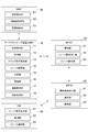
- FIG. 1 shows a configuration of a communication system including a service mapping apparatus 10 according to the present embodiment.
- the communication system is a communication system that allocates services to slices that are virtual networks.
- a slice is a virtual network or service network that is created by logically dividing the network device link and node resources and combining the separated resources, and the slices separate resources. And do not interfere with each other.
- the service refers to a service using network resources such as a communication service (private line service or the like) or an application service (service using a moving image distribution or sensor device such as an embedded device).
- the communication system includes a service mapping device 10, an SO (Service Operator) 20, an OSS / BSS (Operations Support System / Business Support System) 30, an NFVO 40, a VNFM 50, and a VIM (Virtualized Infrastructure Management).
- Virtualization infrastructure management 60, HSS (Home Subscriber Server) 70, DNS (Domain Name System) server 80, MME (Mobility Management Entity) 90 (slice changing device), eNB 100, and SGW (Serving Gateway) 110 (SGW110A to SGW110C), PGW (Packet data network gateway) 120 (PGW120A to PGW120C), and UE (User Equipment) 130.
- NFVO40, VNFM50, and VIM60 are MANO (Management & Orchestration) architecture.
- the identifier of the SGW 110A is “SGW1”, the identifier of the SGW 110B is “SGW2”, and the identifier of the SGW 110C is “SGW3”.
- the identifier of the PGW 120A is “PGW1”, the identifier of the PGW 120B is “PGW2”, and the identifier of the PGW 120C is “PGW3”.
- components constitute the core network of the communication system. Note that components that need to transmit and receive information to each other are connected by wire or the like so that information can be transmitted and received.
- the communication system provides a communication function to the mobile communication terminal (UE 130) by a virtual server that operates in a virtual machine realized on a physical server. That is, the communication system is a virtualized mobile communication network.
- the communication function is provided to the mobile communication terminal by executing a communication process corresponding to the communication function by the virtual machine.
- the service mapping apparatus 10 is a node that performs service management in the communication system and gives instructions related to communication functions in the communication system. Further, the service mapping apparatus 10 can be operated by a telecommunications carrier related to the communication system.
- the SO (Service Operator) 20 is a service requesting device, for example, a terminal device (for example, a personal computer) of a business provider that provides services to various users using a virtual network.
- a service requesting device for example, a terminal device (for example, a personal computer) of a business provider that provides services to various users using a virtual network.
- the OSS / BSS 30 is a device that receives a service request from the SO 20 and notifies the service mapping device 10 of the request.
- the NFVO 40 is an overall management node (functional entity) that manages the entire virtual network (slice) constructed on the NFVI 160, which is a physical resource.
- the NFVO 40 receives an instruction from the service mapping apparatus 10 and performs processing according to the instruction.
- the NFVO 40 performs management over the entire virtual network constructed in the physical resources of the mobile communication network of infrastructure and communication services.
- the NFVO 40 implements a communication service provided by the virtual network at an appropriate location via the VNFM 50 and the VIM 60.
- service life cycle management (specifically, for example, generation, update, scale control, event collection), resource distribution / reservation / allocation management, service / instance management, and policy management (in the mobile communication network) Specifically, for example, resource reservation / allocation, optimal placement based on geography / laws, etc.) is performed.
- the VNFM 50 is a virtual communication function management node (functional entity) that adds a function related to a service to the NFVI 160 serving as a physical resource (node).
- a plurality of VNFMs 50 may be provided in the communication system.
- the VIM 60 is a physical resource management node (functional entity) that manages each physical resource (node). Specifically, resource allocation / update / recovery management, association between physical resources and virtualized network, and management of hardware resources and SW resources (hypervisor) list are performed. Normally, the VIM 60 performs management for each data center (station building). Management of physical resources is performed by a method according to the data center. Data center management methods (management resource mounting methods) include OPENSTACK and vCenter. Normally, the VIM 60 is provided for each data center management method. That is, a plurality of VIMs 60 that manage each physical resource in the NFVI 160 in different manners are included. Note that the unit of physical resources managed by different management methods is not necessarily a data center unit.
- the NFVO 40, the VNFM 50, and the VIM 60 are realized by executing a program on a physical server device (however, they are not limited to being realized on virtualization, and are separated from a management system). And may be realized on virtualization).
- the NFVO 40, the VNFM 50, and the VIM 60 may be realized by separate physical server devices, or may be realized by the same server device.
- the NFVO 40, VNFM 50, and VIM 60 (programs for realizing) may be provided from different vendors.
- the NFVO 40 When the NFVO 40 receives the slice generation request, the NFVO 40 makes a resource securing request for the slice (slice SL1, SL2, etc.) to the VIM 60.
- the VIM 60 secures resources in the server devices and switches that make up physical resources, the NFVO 40 defines slices for these physical resources.
- the NFVO 40 when the NFVO 40 causes the VIM 60 to secure a resource in the physical resource, the NFVO 40 stores information defining a slice for the physical resource in a table stored in the NFVO 40. Then, the NFVO 40 requests the VNFM 50 to install software for realizing functions required for the service. In response to the installation request, the VNFM 50 installs the software on a physical resource (node such as a server device, a switch device, or a router device) secured by the VIM 60.
- a physical resource node such as a server device, a switch device, or a router device
- the slices SL1 to SL3 are slices that are units for allocating services. It is assumed that the identifier (NW Slice ID) of the slice SL1 is “1”, the identifier of the slice SL2 is “2”, and the identifier of the slice SL3 is “3”.
- the NFVO 40 when the NFVO 40 makes a resource securing request for the slice (slice SL1 and slice SL2) to the VIM 60, the VIM 60 gives an instruction to that effect to the physical resources (server device, switch) of the NFVI 160. Then, the NFVO 40 causes the VNFM 50 to install software for realizing the SGW 110 and the PGW 120 for the secured resources.
- the NFVO 40 creates a slice, the NFVO 40 transmits information on the slice to the service mapping apparatus 10.
- the service mapping apparatus 10 allocates services (for example, smartmeter (service for digitally measuring power), MBB (mobile broadband service), voice (voice output service)) based on the information of the slice.
- services for example, smartmeter (service for digitally measuring power), MBB (mobile broadband service), voice (voice output service)
- the slice SL1 includes the SGW 110A and the PGW 120A
- the slice SL2 includes the SGW 110B and the PGW 120B.
- Service types “smartmeter” and “MBB” are assigned to the slice SL1.
- the service type “voice” is assigned to the slice SL2.
- the service type indicates the type of service.
- the service mapping apparatus 10 acquires the resource usage rate for each slice from the NFVO 40, and changes the slice to which the service is allocated based on the resource usage rate. For example, when the resource usage rate of the slice SL1 illustrated in FIG. 2A is equal to or greater than a threshold (for example, 80%) stored in advance, as illustrated in FIG. Service type “MBB” is assigned to slice SL2.
- a threshold for example, 80%
- NFVI 160 which is the above-described physical resource, indicates a network formed from physical resources (node groups) that constitute a virtual environment.
- the physical resources conceptually include computing resources, storage resources, and transmission resources.
- the physical resource includes nodes such as a physical server and a switch that are physical server devices that perform communication processing in the communication system.
- the physical server includes a storage unit such as a CPU (core, processor), a memory, and a hard disk.
- a plurality of nodes such as physical servers that constitute the NFVI 160 are arranged together at a base such as a data center (DC).
- DC data center
- the arranged physical servers are connected by a network inside the data center, and can exchange information with each other.
- the communication system is provided with a plurality of data centers. Data centers are connected by a network, and physical servers provided in different data centers can transmit / receive information to / from each other via the network.
- the NFVI 160 realizes the functions of the HSS 70, the DNS server 80, the MME 90, the SGW 110, and the PGW 120.
- the HSS 70 is a function of managing subscriber information including contract information, authentication information, communication service information, terminal type information, and location information of communication terminals such as the UE 130 in a database.
- the communication service information is information defining the type of communication service used by each UE 130.
- the communication service information includes information for identifying the UE 130 (for example, IMSI (International Mobile Subscriber Identity)) and a service type indicating the communication service used by the UE 130.
- DNS server 80 is a function for managing the correspondence between domain names and host names and IP addresses on the network. Further, the DNS server 80 stores information in which the service type and the address of the SGW 110 are associated with each other. When the DNS server 80 receives an address transmission request from the MME 90, the DNS server 80 transmits the address of the SGW 110 corresponding to the request to the MME 90.
- the MME 90 has a function of performing location management and authentication control of a user terminal (UE 130) located in a LTE (Long Term Evolution) network and setting processing of a communication path of user data between the SGW 110 and the UE 130. That is, the MME 90 is a communication device that is connected to the UE 130 for communication.
- UE 130 user terminal
- LTE Long Term Evolution
- the eNB 100 is a radio base station connected to the MME 90 and a communication device having a radio access control function.
- the eNB 100 acquires the IP address of the service connection destination (for example, the SGW 110) from the MME 90, and connects the UE 130 and the service connection destination using the IP address.
- the service connection destination for example, the SGW 110
- the SGW 110 is a function of a local packet switch that accommodates LTE, and performs transmission / reception of user data used for providing a communication service with a PGW (PacketPackdata120network Gateway) 120.
- PGW PacketPackdata120network Gateway
- a plurality of SGWs 110 are provided corresponding to the requirements of a plurality of communication services.
- the PGW 120 is a junction point with a PDN (Packet data network), and is a gateway that performs IP address assignment, packet transfer to the SGW 110, and the like.
- PDN Packet data network
- the service mapping apparatus 10 includes a request reception unit 11, a holding unit 12, a slice requirement acquisition unit 13, a resource acquisition unit 14, a determination unit 15, an allocation unit 16, and a registration request unit 17. And a switching request unit 18.
- the request accepting unit 11 is a part that accepts a service request including a service requirement that is a functional requirement in the service from the OSS / BSS 30.
- the functional requirement is a requirement related to a function for executing the service.
- the functional requirements include necessity of mobility control, possible access area range, and service usage time.
- the necessity of mobility control means whether handover control is required.
- the access area range means a range (area) where the service is provided.
- the service usage time means a time zone in which the service is used.
- the request receiving unit 11 receives information indicating functional requirements for realizing the service.
- the information indicating the functional requirements for realizing the service is SLA-SL.
- the request reception unit 11 When the request reception unit 11 receives the information indicating the functional requirements for realizing the above service, the request reception unit 11 sends the service requirements to the determination unit 15. In addition, the request reception unit 11 notifies the slice requirement acquisition unit 13 that the slice requirement is acquired.
- the request reception unit 11 When the request reception unit 11 detects that the resource status check timing is predetermined (for example, once per hour), the request reception unit 11 notifies the resource acquisition unit 14 that the resource is acquired, and performs the above check. The determination unit 15 is notified of the timing. In addition, the request reception unit 11 notifies the slice requirement acquisition unit 13 that the slice requirement is acquired even at the resource status check timing.
- the holding unit 12 is a part that stores various tables.
- the holding unit 12 stores a service requirement table, a slice requirement table, and a slice allocation table.
- FIG. 4 shows a service requirement table.
- the service requirement table stores information in which a “Service type” field is associated with a “SLA-SL” field that is a satisfaction request condition.
- the information in the “Service type” column and the “SLA-SL” column is information for identifying a service that has received a service request from the OSS / BSS 30 and is information received from the OSS / BSS 30.
- the example of FIG. 4 indicates that the SLA-SL of the service type “MBB” input in the “Service type” column is “2, 2, 2, 2”.
- the information entered in the “SLA-SL” column in the service requirement table is a numerical representation of the four functions required by the service. These four functions include, for example, those related to mobility, those related to communication delay, data processing capability, and safety.
- FIG. 5 shows a slice requirement table.
- the slice requirement table stores information in which the “NW sliceID” field and the “SLA-SL” field are associated with each other.
- the information in the “NW sliceID” column and the “SLA-SL” column is information received from the NFVO 40.
- a slice whose “NW sliceID” is “1” indicates that the SLA-SL is “2, 2, 2, 2”.
- the service mapping apparatus 10 acquires the information in the “NW sliceID” field and the information in the “SLA-SL” field for the newly generated slice, and Store in the slice requirement table.
- the information input in the “SLA-SL” column in the slice requirement table is a numerical representation of the four functions that a slice can provide. These four functions include, for example, those related to mobility, those related to communication delay, data processing capability, and safety.
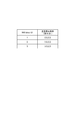
- FIG. 6 shows a slice allocation table.
- information in which the “NW sliceID” field, the “configuration node” field, the “Service type” field, and the “resource usage rate” field are associated with each other is stored.
- Information in the “NW sliceID” column, the “configuration node” column, and the “resource utilization rate” column is information received from the NFVO 40.
- the information in the “Service type” column is information received from the OSS / BSS 30.
- the slice whose “NW sliceID” is “1” has the configuration nodes “SGW1, PGW1”, the service type (Service type) “MBB, smartmeter”, and the resource utilization rate “ 80% ".
- the service mapping apparatus 10 When a new slice is generated by MANO, the service mapping apparatus 10 displays the “NW sliceID” field, the “configuration node” field, the “resource utilization” field, and the “SLA-” for the newly generated slice. Information on the “SL” column is acquired and stored in the slice requirement table and the slice allocation table of the holding unit 12. Further, when the service type to be assigned to the slice is determined, the service mapping apparatus 10 associates it with the “Service type” column of the slice.
- the slice requirement acquisition unit 13 is a part that acquires the requirement (SLA-SL) of each slice with reference to the slice requirement table shown in FIG.
- the slice requirement acquisition unit 13 sends the slice requirement to the determination unit 15.
- the resource acquisition unit 14 When the resource acquisition unit 14 receives a resource acquisition request from the request reception unit 11, it makes a resource acquisition request to the NFVO 40.
- the resource acquisition unit 14 receives resource information from the NFVO 40 in response to the resource acquisition request.
- the resource acquisition unit 14 updates the resource information in the slice allocation table. Further, the resource acquisition unit 14 refers to the slice allocation table in response to a request from the request reception unit 11 and sends the resource usage rate for each slice to the determination unit 15.
- the determining unit 15 is a part that determines a slice corresponding to the service requirement of the service received by the request receiving unit 11. For example, when the request reception unit 11 receives a service allocation request from the OSS / BSS 30, the determination unit 15 receives the SLA-SL received from the request reception unit 11 and the slice illustrated in FIG. 5 acquired from the slice requirement acquisition unit 13.
- the SLA-SL of the requirement table information is compared with the SLA-SL value received from the request accepting unit 11 and includes all the SLA-SL values (greater than or equal to the received SLA-SL value).
- the ID set in the “slice ID” field is determined as the slice ID.
- the determination unit 15 refers to the slice allocation table, and is a case where the same service type as the service type to be allocated is already allocated, and the determined slice ID and the slice ID already allocated to the service type Are different from each other, an allocation request is made to the allocation unit 16.
- the determination unit 15 refers to the service requirement table, and makes an allocation request to the allocation unit 16 when the same service type is not already allocated.
- the determination unit 15 is acquired by the SLA-SL corresponding to each service type in the service requirement table, the SLA-SL in the slice requirement table, and the resource acquisition unit 14. Based on the resource usage status for each slice, a slice to be allocated to the service type to be allocated is determined. Specifically, the determination unit 15 refers to the SLA-SL in the slice requirement table, and has a sufficient resource usage status among the slices satisfying the SLA-SL corresponding to each service type in the slice allocation table (the resource is available). Decide to assign a service type to a slice that has space.
- the determination unit 15 When making an allocation request to the allocation unit 16, the determination unit 15 notifies the terminal information (for example, user ID), the service type, and the slice to be allocated.
- the allocation unit 16 is a part that allocates from the slice associated with the service to be allocated in the slice allocation table to the slice determined by the determination unit 15.
- the allocating unit 16 updates the slice allocation table so that the allocation target service type and the allocation destination slice are associated with each other.
- the registration request unit 17 is a part that requests the DNS server 80 to register the slice and service type changed by the allocation unit 16.
- the registration request unit 17 transmits the slice ID and service type of the changed slice to the DNS server 80.
- the DNS server 80 stores information in which the “Service type” field, the “NW sliceID” field, and the “IP Address” field are associated with each other in response to the registration request.
- the service type is entered in the “Service type” column.
- a slice ID is entered in the “NW sliceID” field.
- IP Address In the “IP Address” column, address information indicating an access destination is input.
- the DNS server 80 Upon receiving the registration request, the DNS server 80 newly registers the service type and the address information when the requested service type information is not input. If the service type has already been registered, the address information corresponding to the service type is changed to the address information to be requested.
- the DNS server 80 further stores information in which the slice ID is associated with the IP address of the device that is the connection destination of the slice indicated by the slice ID.
- the switch request unit 18 is a part that requests the MME 90 to change the service type slice. That is, the switching request unit 18 is a part that requests a change in the connection destination of a service. Specifically, when receiving the changed slice and service type from the assigning unit 16, the switching request unit 18 transmits the changed slice and service type to the MME 90.
- the NFVO 40 includes a holding unit 41, a resource request receiving unit 42, and a resource notification unit 43.
- the holding unit 41 is a part that stores various tables.
- the holding unit 41 stores a function set table and a function requirement table.
- FIG. 8 shows a function set table.
- This function set table is a table that stores information in which the “NW Slice ID” field is associated with the “Function Set” field.
- the “NW Slice ID” column a slice ID for identifying a slice is input.
- Information indicating a function set is input in the “Function set” column.
- FIG. 9 shows a function requirement table.
- the function requirement table is a table that stores information in which the “Function” field and the “SLA-SL” field are associated with each other.
- Information indicating a function is input in the “Function” column illustrated in FIG. 9.
- the “SLA-SL” field information indicating the SLA-SL corresponding to the function is input.
- the resource request receiving unit 42 When the resource request receiving unit 42 receives a resource request from the service mapping apparatus 10, the resource request receiving unit 42 acquires a function set from the function set table of the holding unit 41. The resource request reception unit 42 transmits each function of the function set to the VNFM 50 and makes a VM acquisition request. The resource request receiving unit 42 acquires a VM from the VNFM 50. Subsequently, the resource request receiving unit 42 sends a transmission request for the resource usage status of each VM to the VIM 60. When receiving the resource usage status from the VIM 60, the resource request receiving unit 42 notifies the resource notification unit 43 of the resource usage status for each slice.
- the resource notification unit 43 transmits the resource usage status received from the resource request reception unit 42 to the service mapping apparatus 10 for each slice. Note that the resource notification unit 43 transmits the average value of the resource usage status of the VM corresponding to the slice (VM that realizes the function set of the slice) as the resource usage status of the slice, and among the VMs corresponding to the slice, The value of the largest resource usage status may be transmitted as the resource usage status of the slice.
- the VNFM 50 includes a configuration request receiving unit 51, a holding unit 52, and a search unit 53.
- the configuration request receiving unit 51 is a part that receives a VM acquisition request from the NFVO 40.
- the configuration request receiving unit 51 notifies the search unit 53 of the target function.
- the configuration request receiving unit 51 obtains the search result by the search unit 53 from the search unit 53 after notifying the search unit 53 of the notification.
- the configuration request reception unit 51 acquires the search result from the search unit 53, the configuration request reception unit 51 transmits the search result to the NFVO 40.
- the holding unit 52 is a part that holds various types of information.
- the holding unit 52 holds software (for example, a repository).
- the holding unit 52 stores a VM function table having information associating VMs with functions.
- FIG. 10 shows an example of the VM function table.
- a “Function” column and a “VM” column and an “address” column indicating the address of the “VM”, which are not shown, are stored in association with each other.
- information indicating a function is input.
- information for example, VM identifier
- the search unit 53 is a part that searches the VM function table of the holding unit 52 in response to a request from the configuration request reception unit 51 and notifies the configuration request reception unit 51 of the search result.
- the search unit 53 searches the VM function table and receives a configuration request using “VM” having information in the “Function” column that matches the target function as a search result. To the unit 51.
- the VIM 60 includes a resource request receiving unit 61, a holding unit 62, and a resource notification unit 63.
- the resource request receiving unit 61 is a part that receives a resource status request from the NFVO 40 together with the target VM.
- the resource request receiving unit 61 searches the information in the holding unit 62 using the target VM as a search key.
- the resource request receiving unit 61 notifies the resource notification unit 63 of the search result.
- the holding unit 62 is a part that stores resource information.
- resource information VM usage rate information and hardware usage rate information for realizing the VM are stored.
- FIG. 11 shows an example of VM usage rate information.
- information in which a “VM” field, an “Affiliation HW” field, and a “Usage” field are associated with each other is stored.
- the “VM” column information indicating the VM (for example, an identifier of the VM) is input.
- affiliation HW” column information (for example, an identifier of a server) indicating hardware (for example, a server) that implements the VM is input.
- “Usage” column information indicating the usage rate of the VM is input.
- FIG. 12 shows an example of hardware usage rate information.
- information in which the “HW” column and the “Usage” column are associated with each other is stored.
- Information for identifying hardware is entered in the “HW” column.
- information indicating the usage rate of hardware is input.
- the resource notification unit 63 is a part that receives a search result from the configuration request reception unit 51 and transmits the search result to the NFVO 40.
- the MME 90 includes a switching reception unit 91, a connection destination acquisition unit 92 (acquisition unit), and a connection control unit 93 (notification unit, release unit).
- the switch receiving unit 91 is a part that receives a switch request from the service mapping apparatus 10.
- the switch receiving unit 91 receives the slice ID and the service type from the service mapping apparatus 10 and sends the slice ID and the service type to the connection destination acquiring unit 92 when receiving the switch request.
- the connection destination acquisition unit 92 is a part that acquires the connection destination of the service after the change when the service type slice is changed by the service mapping apparatus 10.
- the connection destination acquisition unit 92 transmits the slice ID and service type to the DNS server 80 and acquires an IP address corresponding to the slice ID and service type.
- the connection destination acquisition unit 92 sends the acquired IP address to the connection control unit 93.
- the connection control unit 93 is a part that performs various connection controls. Specifically, when receiving the IP address corresponding to the slice ID and service type from the DNS server 80, the connection control unit 93 makes a session request to the connection destination of the service. Also, the connection control unit 93 notifies the eNB 100 that the connection destination has been switched. Moreover, the connection control part 93 makes the resource release request
- the service mapping apparatus 10 Physically, the service mapping apparatus 10, the NFVO 40, the VNFM 50, the VIM 60, and the MME 90, as shown in FIG. 13, respectively, one or a plurality of CPUs 101, a main memory RAM 102 and ROM 103, and a data transmission / reception device communication module 104. It is configured as a computer system including an auxiliary storage device 105 (Memory) exemplified by (Transmitter ⁇ ⁇ Receiver), a hard disk, a flash memory, and the like.
- the communication module 104 is operated under the control of the CPU 101 by reading predetermined computer software on the hardware such as the CPU 101 and the RAM 102 shown in FIG. 4, and the RAM 102 and the auxiliary storage device 105.
- a series of functions in the service mapping apparatus 10 is realized by reading and writing data in the service mapping.
- each function is executed by constructing a dedicated integrated circuit (IC: integrated circuit) for all or part of the function.
- IC integrated circuit
- software, instructions, etc. may be transmitted / received via a transmission medium.
- software may use websites, servers, or other devices using wired technology such as coaxial cable, fiber optic cable, twisted pair and digital subscriber line (DSL) and / or wireless technology such as infrared, wireless and microwave.
- wired technology such as coaxial cable, fiber optic cable, twisted pair and digital subscriber line (DSL) and / or wireless technology such as infrared, wireless and microwave.
- DSL digital subscriber line
- wireless technology such as infrared, wireless and microwave.
- the service mapping apparatus 10, NFVO 40, VNFM 50, VIM 60, and MME 90 may be configured by a computer system including a plurality of server apparatuses. Further, nodes other than those described above included in the communication system may also be realized by a server device having the above hardware configuration. Some or all of the functions of eNB 100 and UE 130 (mobile communication terminal) are realized using hardware such as ASIC (Application Specific Integrated Circuit), PLD (Programmable Logic Device), and FPGA (Field Programmable Gate Array). May be. Moreover, eNB100 and UE130 may be implement
- ASIC Application Specific Integrated Circuit
- PLD Programmable Logic Device
- FPGA Field Programmable Gate
- Computer-readable recording media include, for example, flexible disks, magneto-optical disks (for example, compact disks, digital versatile disks, Blu-ray (registered trademark) disks), smart cards, flash memory devices (for example, cards, (Stick, key drive), ROM, EPROM (Erasable Programmable ROM), EEPROM (Electrically Erasable Programmable ROM), CD-ROM (Compact Disc-ROM), RAM, register, removable disk, hard disk, floppy disk, magnetic A strip, database, server or other suitable storage medium.
- the program may be transmitted from a network via a telecommunication line.
- the eNB 100 and the UE 130 may include an input device such as an input key and an output device such as a display.
- the functional configuration of the eNB 100 and the UE 130 may be realized by the hardware described above, may be realized by a software module executed by a processor, or may be realized by a combination of both.
- the processor controls the entire user terminal by operating an operating system. Further, the processor reads programs, software modules and data from the storage medium into the memory, and executes various processes according to these.
- the program may be a program that causes a computer to execute each operation described in the embodiment of the invention.
- the control unit of the mobile communication terminal may be realized by a control program stored in a memory and operated by a processor, and may be similarly realized for other functional blocks.
- processing executed in the communication system according to the present embodiment will be described with reference to the sequence diagram of FIG.
- a processing method for changing the slice allocation based on the resource status at a predetermined timing will be described. It is assumed that a service is assigned to a slice in advance.
- the resource acquisition unit 14 of the service mapping apparatus 10 transmits the slice ID and the function set of the slice to the NFVO 40, acquires the resource usage status, and updates the acquired result in the slice allocation table ( Step S1).
- the resource acquisition unit 14 refers to the slice allocation table and sends the resource usage status of each slice to the determination unit 15.
- the determination unit 15 determines whether there is a slice whose usage rate is tight. For example, as shown in FIG. 6, when the resource usage rate of the slice whose “NW Slice ID” in the slice allocation table is “1” is 80%, it is determined that the usage rate is tight. Since the slice is associated with a plurality of services (MBB, smartmeter), the determination unit 15 assigns any one service to another slice.
- the determination unit 15 sets the MBB as an allocation target service based on a predetermined priority order between service types.
- the determination unit 15 determines the slice to be allocated based on the SLA-SL of each slice and the usage status of the VM of the function set for each slice (step S2). Specifically, the determination unit 15 specifies a record in the slice requirement table having an SLA-SL that satisfies the SLA-SL of the service type stored in the service requirement table, and sets the resource in the slice indicated by the record. Decide to assign to the slice with the most free space. Since the slice with the slice ID 2 satisfies the SLA-SL of the service with the service type MBB, the determination unit 15 determines to allocate to the slice with the slice ID 2. The allocating unit 16 updates the slice allocation table so that the allocation target service type and the allocation destination slice are associated with each other.
- FIG. 15 shows an example of information stored in the DNS server 80 when a service whose service type is MBB is assigned from a slice whose slice ID is 1 to a slice whose slice ID is 2.
- FIG. 15A is an example of information stored in the DNS server 80 before receiving a registration request from the service mapping apparatus 10.
- the service type “MBB” has a slice ID associated with 1. That is, it indicates that the slice with the slice ID 1 is assigned to the service type “MBB”.
- the registration request unit 17 transmits the service type “MBB” and the slice ID “2” to the DNS server 80 and requests the registration.
- the DNS server 80 changes the slice ID corresponding to the service type “MBB” to “2” and the IP corresponding to the service type “MBB”.
- the address is changed to “bb.bb.bb.bb” which is the IP address of slice ID2.
- the switch request unit 18 notifies the MME 90 of the service type and requests a switch (step S4).
- connection destination acquisition unit 92 transmits the service type to the DNS server 80 and requests acquisition of the connection destination information (step S5).
- the connection destination acquisition unit 92 of the MME 90 acquires the connection destination information (IP address) from the DNS server 80 (step S6: acquisition step).
- the connection control unit 93 of the MME 90 transmits the address of the eNB 100, the address of the PGW 120, the address of the connection destination SGW 110B, and the TEID (TunnelTEndpointTIDentifier) generated by the MME 90, and also to the connection destination device (SGW 110B).
- a session request is made (step S7).
- the SGW 110B transmits the IP address and TEID of the SGW 110B to the PGW 120B and makes a bearer update request (Modify bearer request) (step S8).
- the PGW 120B sends a response (Modify bearer response) to the SGW 110B (step S9).
- the SGW 110B When the SGW 110B receives a response from the PGW 120A, it transmits a response (Create session response) to the MME 90 (step S10). Thereby, downlink data flows (step S11).
- the connection control unit 93 of the MME 90 transmits the IP address and TEID of the SGW 110B to the eNB 100 and notifies the start of switching while receiving the above response as a trigger (step S12: notification step). Thereby, uplink data flows from UE130 to PGW120A (step S13).
- the connection control unit 93 of the MME 90 makes a notification of switching completion and a resource release request regarding the SGW 110A to the eNB 100 (step S14: release step). After the switch completion notification, the connection control unit 93 makes a session deletion request to the SGW 110A, receives the response by the session deletion, and ends the process (steps S15 and S16).
- the determination unit 15 of the service mapping apparatus 10 determines a slice having an SLA-SL corresponding to the service requirement (SLA-SL) of the service to be allocated (satisfying the service requirement).
- the assigning unit 16 assigns a service to the slice for which the service to be assigned is determined.
- the connection destination acquisition unit 92 acquires the address of the connection destination (SGW 110B) of the service to be allocated, and the connection control unit 93 notifies the eNB 100 of the IP address of the connection destination before releasing the resources related to the SGW 110A.
- the communication system notifies the eNB 100 of the SGW 110B that is the connection destination of the changed slice before determining the slice that matches the service requirement and before releasing the resources related to the SGW 110A that is the connection destination of the slice before the change. Therefore, it is possible to change the connection destination at the timing when the change of the slice occurs without performing the attach process from the eNB 100 side. That is, the service connection destination can be changed without interruption. As a result, the service can be used without instantaneous interruption.
- connection control unit 93 notifies the eNB 100 of the connection destination address after making a connection request to the service connection destination (SGW 110B).
- SGW 110B service connection destination
- the resource acquisition unit 14 acquires the resource status for each slice at a predetermined timing.
- the slice requirement acquisition unit 13 specifies the SLA-SL of each slice together with the service requirement of the service to which the slice has already been assigned.
- the determination unit 15 determines the slice to be allocated based on the service requirement of the service, the SLA-SL of each slice, and the resource status.
- the connection destination of the service can be dynamically allocated even when the resource status fluctuates.
- judgment used in this specification encompasses a wide variety of actions. “Judgment” can be, for example, calculating, computing, processing, deriving, investigating, looking up (eg, in a table, database, or another data structure Search), ascertaining, and the like. Also, “determining” can include receiving (eg, receiving information), accessing (eg, accessing data in a memory) and the like. Also, “determining” may include resolving, selecting, selecting, establishing, comparing, and the like.
- the phrase “based on” does not mean “based only on”, unless expressly specified otherwise. In other words, the phrase “based on” means both “based only on” and “based at least on.”
- notification of predetermined information is not limited to explicitly performed, but is performed implicitly (for example, notification of the predetermined information is not performed). Also good.
- SYMBOLS 10 Service mapping apparatus, 11 ... Request reception part, 12 ... Holding part, 13 ... Slice requirement acquisition part, 14 ... Resource acquisition part, 15 ... Determination part, 16 ... Assignment part, 17 ... Registration request part, 20 ... SO, 30 ... OSS / BSS, 40 ... NFVO, 41 ... holding unit, 42 ... resource request receiving unit, 43 ... resource notification unit, 50 ... VNFM, 51 ... configuration request receiving unit, 52 ... holding unit, 53 ... search unit, 60 ... VIM, 61 ... resource request receiving unit, 62 ... holding unit, 63 ... resource notifying unit, 70 ... HSS, 80 ... DNS server, 90 ... MME, 91 ...
- switch receiving unit 92 ... connection destination acquiring unit, 93 ... connection Control unit 100 ... eNB 101 ... CPU 102 ... RAM 103 ... ROM 104 ... communication module 105 ... auxiliary storage device 110 ... SGW 120 ... PGW 130 ... E, 160 ... NFVI.
Landscapes
- Engineering & Computer Science (AREA)
- Computer Networks & Wireless Communication (AREA)
- Signal Processing (AREA)
- Software Systems (AREA)
- Quality & Reliability (AREA)
- Theoretical Computer Science (AREA)
- Physics & Mathematics (AREA)
- General Engineering & Computer Science (AREA)
- General Physics & Mathematics (AREA)
- Data Exchanges In Wide-Area Networks (AREA)
- Mobile Radio Communication Systems (AREA)
Abstract
サービスマッピング装置10では、既にスライスが割り当てられているサービスと、当該スライスと、当該サービスを実行する装置を示すアドレスとを対応付けたスライス割当テーブルを記憶している。また、サービスマッピング装置10の依頼受付部11は、機能の要件であるSLA―SLを受信する。決定部15は、割当対象のサービスのサービス要件(SLA―SL)に対応するSLA―SLを有するスライスを決定する。割当部16は、割当対象のサービスを決定されたスライスにサービスを割り当て変更する。接続先取得部92は、割当て対象のサービスの接続先(SGW110B)のアドレスを取得して、接続制御部93は、SGW110Aに関するリソースを解放する前に当該接続先のアドレスをeNB100へ通知する。
Description
本発明は、スライスを変更するスライス変更方法及びスライス変更装置に関する。
従来の仮想化技術を用いたネットワークシステムは、非特許文献1に開示された仮想化技術を用いて、ハードウェア資源を仮想的に切り分けて、ネットワークインフラ上に論理的に生成される仮想ネットワークであるスライスを生成する。そして、当該スライスへサービスを割当てることにより、それぞれ独立したスライスのネットワークを用いてサービス提供することができる。これにより、多様な要求条件を持つサービス各々にスライスを割り当てた場合、サービス個々の要求条件を満たすことを容易にし、そのシグナリング処理などを軽減させることが可能となる。
中尾彰宏、仮想化ノード・プロジェクト新世代のネットワークをめざす仮想化技術、[online]、2010年6月、独立行政法人情報通信研究機構、[2016年1月26日検索]、インターネット<http://www.nict.go.jp/publication/NICT-News/1006/01.html>
しかし、一意にサービスをスライスに割り当ててしまうと、当該サービスの要件が動的に変わる場合や当該スライスを提供するリソースの状況が変化した場合に、常時当該サービスに対して適切なスライスに割り当てているとは限らない。また、リソース利用効率化の観点からもスライスを固定することが適切でない場合もある。よって、状況に応じて動的にスライスを変更する必要がある。スライスの接続先を強制的にリアタッチさせることが考えられるが、この場合、瞬断が発生してしまうという問題がある。
本発明は、上記に鑑みてなされたものであり、スライスを瞬断なく変更するスライス変更方法及びスライス変更装置を提供することを目的とする。
上記目的を達成するために、本発明の一側面に係るスライス変更方法は、ネットワークインフラ上に生成される仮想ネットワークであるスライスを変更する通信システムのスライス変更方法であって、スライスを変更する条件を満たす場合、変更後のスライスの接続先を取得する取得ステップと、スライスを利用する端末とスライスの接続先とを繋げる通信装置へ取得ステップにより取得された接続先を通知する通知ステップと、通知ステップによる通知の後に、変更前のスライスに関するリソースの解放を行う解放ステップと、を含む。
また、本発明の一側面に係るスライス変更装置は、ネットワークインフラ上に生成される仮想ネットワークであるスライスを変更する通信システムに含まれるスライス変更装置であって、スライスを変更する条件を満たす場合、変更後のスライスの接続先を取得する取得手段と、スライスを利用する端末とスライスの接続先とを繋げる通信装置へ前記取得手段により取得された接続先を通知する通知手段と、通知手段による通知の後に、変更前のスライスに関するリソースの解放を行う解放手段と、を備える。
上記のスライス変更方法によれば、スライスを変更する条件を満たした場合に、変更後のスライスの接続先を取得し、変更前のスライスに関するリソースを解放する前に、取得した接続先を通信装置へ通知する。これにより、当該通信装置側から接続先の変更の問合せをすることなく、スライスを変更したタイミングで接続先を変更することができる。すなわち、スライスを瞬断なく変更することができる。
上記のスライス変更方法では、通知ステップは、スライスの接続先へ接続要求をした後に、通知を行ってもよい。この場合、サービスの接続先へ接続要求した後に通知を行うので、当該通知に応じて端末からサービスの接続先へ適切に接続することができる。
上記のスライス変更方法では、条件は、スライスのリソース使用状況に基づいて定められ、取得ステップは、スライス毎のリソース使用状況に応じて定められた変更後のスライスの接続先を取得してもよい。この場合、リソース使用状況に応じて割当てられるスライスが定まるので、リソース負荷に基づいてサービスの接続先を変更することができる。
上記のスライス変更方法では、端末が利用するサービスは、スライスに割り当てられており、スライスを変更する条件を満たす場合、変更後のスライスへサービスが割当てられてもよい。この場合、変更前のスライスに関するリソースを解放する前に、サービスが割り当てられたスライスの接続先を通信装置へ通知するので、瞬断無くサービスを利用することができる。
スライスを瞬断なく変更することができる。
以下、図面と共に本発明の一側面に係るスライス割当方法の実施形態について詳細に説明する。なお、図面の説明においては同一要素には同一符号を付し、重複する説明を省略する。
図1に本実施形態に係るサービスマッピング装置10を含む通信システムの構成を示す。通信システムは、仮想ネットワークであるスライスに対してサービスを割り当てる通信システムである。スライスとは、ネットワーク装置のリンクとノードの資源を仮想的に切り分けて、切り分けた資源を結合し、ネットワークインフラ上に論理的に生成される仮想ネットワーク又はサービス網であり、スライス同士は資源を分離しており、互いに干渉しない。サービスとは、通信サービス(専用線サービス等)やアプリケーションサービス(動画配信、エンベデッド装置等のセンサ装置を利用したサービス)等のネットワーク資源を用いたサービスをいう。
図1に示すように通信システムは、サービスマッピング装置10と、SO(Service Operator)20と、OSS/BSS(Operations Support System/Business Support System)30と、NFVO40と、VNFM50と、VIM(Virtualized Infrastructure Management:仮想化基盤管理)60と、HSS(Home Subscriber Server)70と、DNS(Domain Name System)サーバ80と、MME(Mobility Management Entity)90(スライス変更装置)と、eNB100と、SGW(Serving Gateway)110(SGW110A~SGW110C)と、PGW(Packet data network gateway)120(PGW120A~PGW120C)と、UE(User Equipment)130とを含んで構成されている。このうち、NFVO40とVNFM50とVIM60とは、MANO(Management & Orchestration)architectureである。なお、SGW110Aの識別子は、「SGW1」であり、SGW110Bの識別子は、「SGW2」であり、SGW110Cの識別子は、「SGW3」である。PGW120Aの識別子は、「PGW1」であり、PGW120Bの識別子は、「PGW2」であり、PGW120Cの識別子は、「PGW3」である。
これらの構成要素は、通信システムのコアネットワークを構成するものである。なお、互いに情報の送受信が必要な構成要素間は、有線等で接続されており情報の送受信が可能となっている。
本実施形態に係る通信システムは、物理サーバ上に実現される仮想マシンにおいて動作する仮想サーバによって移動通信端末(UE130)に対して通信機能を提供する。即ち、通信システムは、仮想化された移動体通信ネットワークである。通信機能は、仮想マシンによって当該通信機能に応じた通信処理を実行することで移動通信端末に対して提供される。
サービスマッピング装置10は、通信システムにおけるサービス管理を行い、通信システムでの通信機能に係る指示を行うノードである。また、サービスマッピング装置10は、通信システムに係る通信事業者によって操作され得る。
SO(Service Operator)20は、サービス要求する装置であり、例えば、仮想ネットワークを用いて各種ユーザへサービス提供をする事業者の端末装置(例えば、パーソナルコンピュータ等)である。
OSS/BSS30は、SO20からのサービス要求を受け付けて、サービスマッピング装置10へその要求を通知する装置である。
NFVO40は、物理資源であるNFVI160上に構築された仮想ネットワーク(スライス)全体の管理を行う全体管理ノード(機能エンティティ)である。NFVO40は、サービスマッピング装置10からの指示を受信し、当該指示に応じた処理を行う。NFVO40は、インフラと通信サービスの移動体通信網の物理資源において構築された仮想化ネットワーク全体にわたる管理を行う。NFVO40は、仮想ネットワークにより提供される通信サービスをVNFM50及びVIM60を経由して適切な場所に実現する。例えば、サービスのライフサイクル管理(具体的には例えば、生成、更新、スケール制御、イベント収集)、移動体通信網内全体にわたる資源の分散・予約・割当管理、サービス・インスタンス管理、及びポリシー管理(具体的には例えば、リソースの予約・割当、地理・法令等に基づく最適配置)を行う。
VNFM50は、物理資源(ノード)となるNFVI160に対して、サービスに係る機能を追加する仮想通信機能管理ノード(機能エンティティ)である。VNFM50は、通信システムに複数設けられていてもよい。
VIM60は、物理資源(ノード)各々を管理する物理資源管理ノード(機能エンティティ)である。具体的には、資源の割当・更新・回収の管理、物理資源と仮想化ネットワークとの関連付け、ハードウェア資源とSW資源(ハイパーバイザー)一覧の管理を行う。通常、VIM60は、データセンタ(局舎)毎に管理を行う。物理資源の管理は、データセンタに応じた方式で行われる。データセンタの管理方式(管理資源の実装方式)は、OPENSTACKやvCenter等の種類がある。通常、VIM60は、データセンタの管理方式毎に設けられる。即ち、互いに異なる方式で、NFVI160における物理資源各々を管理する複数のVIM60が含まれる。なお、異なる管理方式で管理される物理資源の単位は、必ずしもデータセンタ単位でなくてもよい。
なお、NFVO40、VNFM50及びVIM60は、物理的なサーバ装置上でプログラムが実行されることにより実現される(但し仮想化上で実現されることを制限するものでは無く、管理系統を分離した上で、仮想化上で実現してもよい)。NFVO40、VNFM50及びVIM60は、それぞれ別々の物理的なサーバ装置で実現されていてもよいし、同じサーバ装置で実現されていてもよい。NFVO40、VNFM50及びVIM60(を実現するためのプログラム)は、別々のベンダから提供されていてもよい。
NFVO40は、スライス生成要求を受信すると、VIM60に対してスライス(スライスSL1、SL2等)のためのリソース確保要求を行う。VIM60が、物理資源を構成するサーバ装置やスイッチにおけるリソースを確保すると、NFVO40は、当該これら物理資源に対してスライスを定義する。
また、NFVO40は、VIM60に、物理資源においてリソース確保させると、当該物理資源に対してスライスを定義した情報をNFVO40が記憶しているテーブルに記憶する。そして、NFVO40は、サービスに必要となる機能を実現するためのソフトウェアのインストール要求をVNFM50に対して行う。VNFM50は、当該インストール要求に応じて、VIM60によって確保された物理資源(サーバ装置、スイッチ装置またはルータ装置などのノード)に対して上記ソフトウェアをインストールする。
NFVO40は、VNFM50によりソフトウェアがインストールされると、NFVO40が記憶しているテーブルへスライスと上記インストールにより実現される機能との対応付けをする。スライスSL1~スライスSL3は、サービスを割り当てる単位となるスライスである。スライスSL1の識別子(NW SliceID)は、「1」であり、スライスSL2の識別子は、「2」であり、スライスSL3の識別子は、「3」であるものとする。
例えば、NFVO40がスライス(スライスSL1及びスライスSL2)のためのリソース確保要求をVIM60へ行うと、VIM60は、その旨の指示をNFVI160の物理資源(サーバ装置、スイッチ)へ行う。そして、NFVO40は、確保したリソースに対して、SGW110、PGW120を実現するためのソフトウェアをVNFM50に対してインストールさせる。NFVO40は、スライスを作成すると、当該スライスの情報をサービスマッピング装置10に送信する。サービスマッピング装置10は、当該スライスの情報に基づいて、サービス(例えば、smartmeter(電力をデジタルで計測するサービス)、MBB(モバイルブロードバンドサービス)、voice(音声出力サービス))を割当てる。
例えば、図2(A)に示すように、スライスSL1は、SGW110A及びPGW120Aを有し、スライスSL2は、SGW110B及びPGW120Bを有する。スライスSL1には、サービスタイプ「smartmeter」及び「MBB」が割り当てられている。また、スライスSL2には、サービスタイプ「voice」が割り当てられている。サービスタイプとは、サービスの種類を示すものである。
サービスマッピング装置10は、NFVO40からスライス毎のリソース使用率を取得し、当該リソース使用率に基づいて、サービスを割当てるスライスを変更する。例えば、図2(A)に示すスライスSL1のリソース使用率が、予め記憶している閾値(例えば、80%)以上である場合、図2(B)に示すように、サービスマッピング装置10は、サービスタイプ「MBB」をスライスSL2に割当てる。
上述の物理資源であるNFVI160は、仮想化環境を構成する物理資源(ノード群)から形成されたネットワークを示す。この物理資源は、概念的には計算資源、記憶資源、伝送資源を含む。具体的には、この物理資源は、通信システムにおいて通信処理を行う物理的なサーバ装置である物理サーバ、スイッチ等のノードを含んで構成されている。物理サーバは、CPU(コア、プロセッサ)、メモリ、及びハードディスク等の記憶手段を備えて構成される。通常、NFVI160を構成する物理サーバ等のノードは、複数まとめてデータセンタ(DC)等の拠点に配置される。データセンタでは、配置された物理サーバがデータセンタ内部のネットワークによって接続されており、互いに情報の送受信を行うことができるようになっている。また、通信システムには、複数のデータセンタが設けられている。データセンタ間はネットワークで接続されており、異なるデータセンタに設けられた物理サーバはそのネットワークを介して互いに情報の送受信を行うことができる。
上述のように、VNFM50が、物理資源(ノード)となるNFVI160に対して、各種機能を追加することにより、NFVI160は、HSS70、DNSサーバ80、MME90、SGW110、及びPGW120の機能を実現する。
HSS70は、UE130等の通信端末の契約情報、認証情報、通信サービス情報、端末タイプ情報及び在圏情報を含む加入者情報をデータベースで管理する機能である。ここで、通信サービス情報とは、各UE130が利用する通信サービスのタイプを定義した情報である。通信サービス情報には、UE130を識別する情報(例えば、IMSI(International Mobile Subscriber Identity))と、当該UE130が利用する通信サービスを示すサービスタイプとが含まれる。
DNSサーバ80は、ネットワーク上でドメイン名やホスト名とIPアドレスの対応関係を管理する機能である。さらにDNSサーバ80は、サービスタイプとSGW110のアドレスとを対応付けた情報を記憶している。DNSサーバ80は、MME90からアドレスの送信要求を受け付けると、要求に応じたSGW110のアドレスをMME90へ送信する。
MME90は、LTE(Long Term Evolution)ネットワークに在圏するユーザ端末(UE130)の位置管理、認証制御、及びSGW110とUE130との間のユーザデータの通信経路の設定処理を行う機能である。すなわち、MME90は、UE130と通信接続する通信装置である。
eNB100は、MME90に接続された無線基地局であるとともに、無線アクセス制御機能を有した通信装置である。eNB100は、MME90からサービスの接続先(例えば、SGW110)のIPアドレスを取得し、当該IPアドレスを用いてUE130とサービスの接続先とを繋げる。
SGW110は、LTEを収容する在圏パケット交換機の機能で、PGW(Packet data network Gateway)120との間で通信サービス提供に利用されるユーザデータの送受信を行う。SGW110は、複数の通信サービスの要件に対応して複数設けられている。
PGW120は、PDN(Packet data network)との接合点であり、IPアドレスの割当てや、SGW110へのパケット転送などを行うゲートウェイである。
引き続いて、サービスマッピング装置10、NFVO40、VNFM50、VIM60、及びMME90について、本実施形態に係る機能について図3を用いて説明する。
図3に示すようにサービスマッピング装置10は、依頼受付部11と、保持部12と、スライス要件取得部13と、リソース取得部14と、決定部15と、割当部16と、登録要求部17と、切替要求部18とを有する。
依頼受付部11は、OSS/BSS30からのサービスにおける機能の要件であるサービス要件を含むサービス依頼を受け付ける部分である。ここで、サービス要件の内、機能要件とはサービスを実行するための機能に関する要件である。具体的には、機能要件としてモビリティ制御の要否、可能アクセスエリア範囲、サービス利用時間が含まれる。モビリティ制御の要否とは、ハンドオーバ制御を必要とするか否かを意味する。アクセスエリア範囲は、サービスを提供する範囲(エリア)を意味する。サービス利用時間は、サービスを利用する時間帯を意味する。
また、依頼受付部11は、サービス依頼を受け付ける際に、サービスを実現するための機能の要件を示す情報を受信する。ここでいうサービスを実現するための機能の要件を示す情報としては、SLA-SLである。
依頼受付部11は、上記のサービスを実現するための機能の要件を示す情報を受信すると、サービス要件を決定部15へ送出する。また、依頼受付部11は、スライス要件取得部13に対して、スライス要件を取得する旨の通知をする。
また、依頼受付部11は、予め定められているリソース状況チェックタイミング(例えば、1時間に1回)であることを検知すると、リソース取得部14へリソース取得する旨の通知をすると共に、上記チェックタイミングである旨を決定部15へ通知する。また、依頼受付部11は、リソース状況チェックタイミングである場合も、スライス要件取得部13に対して、スライス要件を取得する旨の通知をする。
保持部12は、各種テーブルを記憶する部分である。保持部12は、サービス要件テーブル、スライス要件テーブル、及びスライス割当テーブルを記憶する。図4に、サービス要件テーブルを示す。図4に示すように、サービス要件テーブルは、「Service type」欄と充足要求条件である「SLA-SL」欄とを対応付けた情報を記憶する。ここで、「Service type」欄及び「SLA-SL」欄の情報は、OSS/BSS30からサービス要求を受け付けたサービスを特定する情報であり、OSS/BSS30から受信する情報である。図4の例では、「Service type」欄に入力されている「MBB」であるサービスタイプのSLA-SLが「2,2,2,2」であることを示す。サービス要件テーブルにおける「SLA-SL」欄に入力される情報は、サービスが要求する4つの機能を数値化したものである。この4つの機能は、例えば、移動性に関するもの、通信遅延に関するもの、データ処理能力に関するもの、及び安全性に関するもの等である。
続いて、図5に、スライス要件テーブルを示す。図5に示すように、スライス要件テーブルは、「NW sliceID」欄と「SLA-SL」欄とを対応付けた情報を記憶する。「NW sliceID」欄及び「SLA-SL」欄の情報は、NFVO40から受信する情報である。図5の例では、「NW sliceID」が「1」であるスライスは、SLA-SLが「2,2,2,2」であることを示す。MANOでスライスが新規に生成されると、サービスマッピング装置10は、新規に生成されたスライスについての「NW sliceID」欄の情報と「SLA-SL」欄の情報とを取得し、保持部12のスライス要件テーブルに記憶する。スライス要件テーブルにおける「SLA-SL」欄に入力される情報は、スライスが提供可能な4つの機能を数値化したものである。この4つの機能は、例えば、移動性に関するもの、通信遅延に関するもの、データ処理能力に関するもの、及び安全性に関するもの等である。
続いて、図6に、スライス割当テーブルを示す。図6に示すように、「NW sliceID」欄と、「構成ノード」欄と、「Service type」欄と、「リソース利用率」欄とを対応付けた情報を記憶する。「NW sliceID」欄、「構成ノード」欄、及び「リソース利用率」欄の情報は、NFVO40から受信する情報である。「Service type」欄の情報は、OSS/BSS30から受信する情報である。図6の例では、「NW sliceID」が「1」であるスライスは、構成ノードが「SGW1、PGW1」であり、サービスタイプ(Service type)が「MBB,smartmeter」であり、リソース利用率が「80%」であることを示す。MANOでスライスが新規に生成されると、サービスマッピング装置10は、新規に生成されたスライスについての「NW sliceID」欄と、「構成ノード」欄と、「リソース利用率」欄と、「SLA-SL」欄との情報を取得し、保持部12のスライス要件テーブル及びスライス割当テーブルに記憶する。また、サービスマッピング装置10は、スライスに割り当てるサービスタイプが決まると、当該スライスの「Service type」欄に対応付ける。
スライス要件取得部13は、保持部12で記憶している、図5に示したスライス要件テーブルを参照して、各スライスの要件(SLA-SL)を取得する部分である。スライス要件取得部13は、当該スライスの要件を取得すると、決定部15へ送出する。
リソース取得部14は、依頼受付部11からリソース取得要求を受け付けると、NFVO40へリソース取得要求をする。リソース取得部14は、当該リソース取得要求に応じて、NFVO40からリソース情報を受信する。リソース取得部14は、当該リソース情報をスライス割当テーブルへ更新する。また、リソース取得部14は、依頼受付部11の要求に応じてスライス割当テーブルを参照し、スライス毎のリソース利用率を決定部15へ送出する。
決定部15は、依頼受付部11によって受け付けられたサービスのサービス要件に対応するスライスを決定する部分である。例えば、決定部15は、依頼受付部11がOSS/BSS30からサービス割当要求を受け付けた場合、依頼受付部11から受信したSLA―SLと、スライス要件取得部13から取得した図5に示したスライス要件テーブルの情報のSLA―SLとを比較して、依頼受付部11から受信したSLA―SLの値を全て包含する(受信したSLA―SLの値以上である)スライス要件テーブルの情報の「NW sliceID」欄に設定されているIDをスライスIDとして決定する。決定部15は、スライス割当テーブルを参照し、割当対象のサービスタイプと同一のサービスタイプが既に割り当てられている場合であり、上記決定したスライスIDと、上記サービスタイプに既に割り当てられているスライスIDとが異なる場合、割当部16へ割り当て要求をする。また、決定部15は、サービス要件テーブルを参照し、既に同一のサービスタイプが割り当てられていない場合は、割当部16へ割り当て要求する。
また、決定部15は、リソース取得部14からリソース情報を取得した場合、サービス要件テーブルの各サービスタイプに対応するSLA―SLと、スライス要件テーブルのSLA―SLと、リソース取得部14によって取得されたスライス毎のリソース使用状況とに基づいて、割当対象のサービスタイプに割り当てるスライスを決定する。具体的には、決定部15は、スライス要件テーブルのSLA―SLを参照し、スライス割当テーブルの各サービスタイプに対応するSLA―SLを満たすスライスの内、リソース使用状況に余裕のある(リソースに空きがある)スライスにサービスタイプを割り当てることを決定する。ここでリソース使用状況に余裕があるとは、スライス毎のリソース(当該スライスを構成するVM又は、当該VMを実現するハードウェア)の利用率の平均値が最も低いことをいう。この場合に、今回決定したスライスと、前回割り当てていたスライスが異なる場合、割当部16へ割り当て要求をする。決定部15は、割当部16へ割当要求する場合、端末情報(例えば、ユーザID)、サービスタイプ、及び割り当てるスライスを通知する。
割当部16は、スライス割当テーブルにより割当対象のサービスに対応付けられているスライスから、決定部15により決定されたスライスへ割当てる部分である。割当部16は、割当対象のサービスタイプと、割当先のスライスを対応付けるようにスライス割当テーブルを更新する。
登録要求部17は、DNSサーバ80に対して、割当部16により変更されたスライスとサービスタイプとを登録要求する部分である。登録要求部17は、変更後のスライスのスライスIDとサービスタイプとをDNSサーバ80へ送信する。
ここで、DNSサーバ80が記憶している情報の例を図7に示す。DNSサーバ80は、図7に示すように、「Service type」欄と「NW sliceID」欄と「IP Address」欄とを対応付けた情報を上記登録要求に応じて記憶する。「Service type」欄には、サービスタイプが入力される。「NW sliceID」欄には、スライスIDが入力される。「IP Address」欄には、アクセス先を示すアドレス情報が入力される。DNSサーバ80は、上記登録要求を受信すると、要求対象のサービスタイプの情報が入力されていない場合には、新たにサービスタイプと、上記アドレス情報を登録する。既にサービスタイプが登録されている場合には、当該サービスタイプに対応するアドレス情報を、要求対象のアドレス情報に変更する。なお、DNSサーバ80は、スライスIDと、当該スライスIDが示すスライスの接続先となる装置のIPアドレスとを対応付けた情報をさらに記憶している。
切替要求部18は、MME90へサービスタイプのスライス変更を依頼する部分である。すなわち、切替要求部18は、サービスの接続先の変更依頼をする部分である。具体的には、切替要求部18は、割当部16から変更後のスライス及びサービスタイプを受け付けると、当該変更後のスライス及びサービスタイプをMME90へ送信する。
続いて、NFVO40の機能の説明をする。NFVO40は、保持部41と、リソース要求受付部42と、リソース通知部43とを備える。
保持部41は、各種テーブルを記憶する部分である。保持部41は、ファンクションセットテーブル及びファンクション要件テーブルを記憶する。図8にファンクションセットテーブルを示す。このファンクションセットテーブルは、「NW Slice ID」欄と「Funciton Set」欄とを対応付けた情報を記憶するテーブルである。「NW Slice ID」欄には、スライスを識別するスライスIDが入力されている。「Funciton Set」欄には、ファンクションセットを示す情報が入力されている。図9にファンクション要件テーブル示す。ファンクション要件テーブルは、「Function」欄と「SLA-SL」欄とを対応付けた情報を記憶するテーブルである。図9に示す「Funciton」欄には、ファンクションを示す情報が入力されている。また、「SLA-SL」欄には、当該ファンクションに対応するSLA-SLを示す情報が入力されている。
リソース要求受付部42は、サービスマッピング装置10からリソース要求を受け付けると、保持部41のファンクションセットテーブルからファンクションセットを取得する。リソース要求受付部42は、当該ファンクションセットのそれぞれの機能をVNFM50へ送信し、VM取得要求をする。リソース要求受付部42は、VNFM50からVMを取得する。続いて、リソース要求受付部42は、それぞれのVMのリソース利用状況の送信要求をVIM60へ行う。リソース要求受付部42は、VIM60からリソース利用状況を受信すると、当該リソース利用状況をスライス毎にリソース通知部43へ通知する。
リソース通知部43は、リソース要求受付部42から受信したリソース利用状況をスライス毎にサービスマッピング装置10へ送信する。なお、リソース通知部43は、スライスに対応するVM(スライスのファンクションセットを実現うするVM)のリソース利用状況の平均値をスライスのリソース利用状況として送信したり、スライスに対応するVMの内、最も大きいリソース利用状況の値をスライスのリソース利用状況として送信したりしてもよい。
続いて、VNFM50の説明をする。VNFM50は、構成要求受付部51と、保持部52と、検索部53とを有する。構成要求受付部51は、NFVO40からのVM取得要求を受け付ける部分である。構成要求受付部51は、NFVO40から対象機能と共にVM取得要求を受け付けると、当該対象機能を検索部53へ通知する。構成要求受付部51は、検索部53に当該通知をした後に、検索部53による検索結果を検索部53から取得する。構成要求受付部51は、検索結果を検索部53から取得すると、検索結果をNFVO40へ送信する。
保持部52は、各種情報を保持する部分である。保持部52は、ソフトウェア(例えば、リポジトリ)を保持する。また、保持部52は、上記ソフトウェア以外に、VMと機能とを対応付けた情報有するVM機能テーブルを記憶する。図10にVM機能テーブルの例を示す。図10に示すように、「Function」欄と「VM」欄と、図示していないが、当該「VM」のアドレスを示す「アドレス」欄とを対応付けて記憶している。「Function」欄には、ファンクションを示す情報が入力されている。「VM」欄には、当該ファンクションを実行するVMを示す情報(例えば、VMの識別子等)が入力される。
検索部53は、構成要求受付部51からの要求に応じて、保持部52のVM機能テーブルを検索して、その検索結果を構成要求受付部51へ通知する部分である。検索部53は、構成要求受付部51から対象機能を受信すると、VM機能テーブルを検索して、当該対象機能に合致する「Function」欄の情報を有する「VM」を検索結果として、構成要求受付部51へ送信する。
VIM60は、リソース要求受付部61と、保持部62と、リソース通知部63とを備える。リソース要求受付部61は、NFVO40から、対象VMと共にリソース状況の要求を受け付ける部分である。リソース要求受付部61は、リソース状況要求受け付けると、対象VMを検索キーとして、保持部62の情報を検索する。リソース要求受付部61は、検索結果をリソース通知部63へ通知する。
保持部62は、リソース情報を記憶する部分である。リソース情報として、VMの使用率情報及び当該VMを実現するハードウェアの使用率情報を記憶する。図11にVMの使用率情報例を示す。図11に示すように、「VM」欄と、「所属HW」欄と、「Usage」欄とを対応付けた情報を記憶している。「VM」欄には、VMを示す情報(例えば、VMの識別子)が入力されている。「所属HW」欄には、VMを実現するハードウェア(例えば、サーバ)を示す情報(例えば、サーバの識別子)が入力されている。「Usage」欄には、VMの使用率を示す情報が入力されている。続いて、図12にハードウェアの使用率情報の例を示す。図12に示すように、「HW」欄と、「Usage」欄とを対応付けた情報を記憶している。「HW」欄には、ハードウェアを識別する情報が入力されている。「Usage」欄には、ハードウェアの使用率を示す情報が入力されている。
リソース通知部63は、構成要求受付部51から検索結果を受信し、当該検索結果をNFVO40へ送信する部分である。
続いて、MME90の説明をする。MME90は、切替受付部91と、接続先取得部92(取得手段)と、接続制御部93(通知手段、解放手段)とを有する。切替受付部91は、サービスマッピング装置10からの切替要求を受け付ける部分である。切替受付部91は、サービスマッピング装置10からスライスID及びサービスタイプを受信すると共に、切替要求を受信すると、スライスID及びサービスタイプを接続先取得部92へ送出する。
接続先取得部92は、サービスマッピング装置10によりサービスタイプのスライスが変更された場合に変更後のサービスの接続先を取得する部分である。接続先取得部92は、切替受付部91からスライスID及びサービスタイプを取得すると、当該スライスID及びサービスタイプをDNSサーバ80へ送信すると共に、当該スライスID及びサービスタイプに対応するIPアドレスを取得する。接続先取得部92は、取得したIPアドレスを接続制御部93へ送出する。
接続制御部93は、各種接続制御をする部分である。具体的には、接続制御部93は、上記スライスID及びサービスタイプに対応するIPアドレスをDNSサーバ80から受信すると、サービスの接続先へセッション要求をする。また、接続制御部93は、eNB100へ接続先を切り替えた旨の通知をする。また、接続制御部93は、上記通知をした後に、eNB100に対して、SGW110Aに関するリソース解放要求をする。
物理的には、サービスマッピング装置10、NFVO40、VNFM50、VIM60及びMME90は、それぞれ図13に示すように、一又は複数のCPU101、主記憶装置であるRAM102及びROM103、データ送受信デバイスである通信モジュール104(Transmitter or Receiver)、ハードディスク、フラッシュメモリ等に例示される補助記憶装置105(Memory)などを含むコンピュータシステムとして構成されている。サービスマッピング装置10では、図4に示すCPU101、RAM102等のハードウェア上に所定のコンピュータソフトウェアを読み込ませることにより、CPU101の制御のもとで通信モジュール104を動作させるとともに、RAM102や補助記憶装置105におけるデータの読み出し及び書き込みを行うことで、サービスマッピング装置10における一連の機能が実現される。
なお、CPU101などのプロセッサ(Processor)が図3における各機能を実行することに代えて、その機能全部または一部を専用の集積回路(IC:integrated circuit)を構築することにより各機能を実行するように構成してもよい。例えば、画像処理や通信制御を行なうための専用の集積回路を構築することにより上記機能を実行するようにしてもよい。
ソフトウェアは、ソフトウェア、ファームウェア、ミドルウェア、マイクロコード、ハードウェア記述言語と呼ばれるか、他の名称で呼ばれるかを問わず、命令、命令セット、コード、コードセグメント、プログラムコード、プログラム、サブプログラム、ソフトウェアモジュール、アプリケーション、ソフトウェアアプリケーション、ソフトウェアパッケージ、ルーチン、サブルーチン、オブジェクト、実行可能ファイル、実行スレッド、手順、機能などを意味するよう広く解釈されるべきである。
また、ソフトウェア、命令などは、伝送媒体を介して送受信されてもよい。例えば、ソフトウェアが、同軸ケーブル、光ファイバケーブル、ツイストペア及びデジタル加入者回線(DSL)などの有線技術及び/又は赤外線、無線及びマイクロ波などの無線技術を使用してウェブサイト、サーバ、又は他のリモートソースから送信される場合、これらの有線技術及び/又は無線技術は、伝送媒体の定義内に含まれる。
なお、サービスマッピング装置10、NFVO40、VNFM50、VIM60及びMME90は複数のサーバ装置からなるコンピュータシステムによって構成されていてもよい。また、通信システムに含まれる上記以外のノードも上記のハードウェア構成を有するサーバ装置によって実現されてもよい。また、eNB100やUE130(移動通信端末)の各機能の一部又は全ては、ASIC(Application Specific Integrated Circuit)、PLD(Programmable Logic Device)、FPGA(Field Programmable Gate Array)などのハードウェアを用いて実現されても良い。また、eNB100やUE130は、プロセッサ(CPU)と、ネットワーク接続用の通信インターフェースと、メモリと、プログラムを保持したコンピュータ読み取り可能な記憶媒体と、を含むコンピュータ装置によって実現されてもよい。つまり、本発明の一実施形態に係るeNB100やUE130などは、本発明の一側面に係る処理を行うコンピュータとして機能してもよい。
ここで、プロセッサやメモリなどは情報を通信するためのバスで接続される。また、コンピュータ読み取り可能な記録媒体は、例えば、フレキシブルディスク、光磁気ディスク(例えば、コンパクトディスク、デジタル多用途ディスク、Blu-ray(登録商標)ディスク)、スマートカード、フラッシュメモリデバイス(例えば、カード、スティック、キードライブ)、ROM、EPROM(Erasable Programmable ROM)、EEPROM(Electrically Erasable Programmable ROM)、CD-ROM(Compact Disc-ROM)、RAM、レジスタ、リムーバブルディスク、ハードディスク、フロッピー(登録商標)ディスク、磁気ストリップ、データベース、サーバその他の適切な記憶媒体である。また、プログラムは、電気通信回線を介してネットワークから送信されても良い。また、eNB100やUE130は、入力キーなどの入力装置や、ディスプレイなどの出力装置を含んでいてもよい。
eNB100及びUE130の機能構成は、上述のハードウェアによって実現されてもよいし、プロセッサによって実行されるソフトウェアモジュールによって実現されてもよいし、両者の組み合わせによって実現されてもよい。プロセッサは、オペレーティングシステムを動作させてユーザ端末の全体を制御する。また、プロセッサは、記憶媒体からプログラム、ソフトウェアモジュールやデータをメモリに読み出し、これらに従って各種の処理を実行する。
ここで、当該プログラムは、発明の実施形態で説明する各動作を、コンピュータに実行させるプログラムであれば良い。例えば、移動通信端末の制御部は、メモリに格納され、プロセッサで動作する制御プログラムによって実現されてもよく、他の機能ブロックについても同様に実現されてもよい。
続いて、図14のシーケンス図を用いて、本実施形態に係る通信システムで実行される処理を説明する。ここでは、所定のタイミングでリソースの状況に基づいて、スライスの割当変更をする処理方法について説明する。なお、予めスライスにサービスが割り当てられているものとする。
所定のタイミングで、サービスマッピング装置10のリソース取得部14は、NFVO40へスライスIDと当該スライスのファンクションセットを送信すると共にリソースの利用状況を取得して、取得した結果をスライス割当テーブルに更新する(ステップS1)。所定のタイミングでリソース取得部14は、スライス割当テーブルを参照し、各スライスのリソース利用状況を決定部15へ送出する。決定部15は、利用率が逼迫しているスライスがあるか否かを判断する。例えば、図6に示すようにスライス割当テーブルにおける「NW Slice ID」が「1」であるスライスのリソース利用率が80%である場合、利用率が逼迫していると判断する。なお、当該スライスは、複数のサービス(MBB、smartmeter)が対応付いているので、決定部15は、何れか一つのサービスを他のスライスへ割り当てる。ここでは、決定部15は、予め定められているサービスタイプ間の優先順位に基づいてMBBを割当て対象のサービスとする。
続いて、決定部15は、各スライスのSLA―SLと、スライス毎のファンクションセットのVMの使用状況に基づいて、割り当てるスライスを決定する(ステップS2)。具体的には、決定部15は、サービス要件テーブルで記憶されているサービスタイプのSLA―SLを満たすSLA―SLを有するスライス要件テーブルのレコードを特定し、当該レコードが示すスライスの内、リソースに最も空きがあるスライスに割り当てると決定する。スライスIDが2であるスライスは、サービスタイプがMBBであるサービスのSLA―SLを満たすので、決定部15は、スライスIDが2であるスライスに割り当てると決定する。割当部16は、割当対象のサービスタイプと、割当先のスライスを対応付けるようにスライス割当テーブルを更新する。
続いて、登録要求部17は、DNSサーバ80へサービスタイプに対応するスライスの登録要求をする(ステップS3)。ここで、サービスタイプがMBBであるサービスを、スライスIDが1であるスライスからスライスIDが2であるスライスに割り当てる場合における、DNSサーバ80で記憶している情報の例を図15に示す。図15(A)は、サービスマッピング装置10から登録要求を受ける前におけるDNSサーバ80で記憶している情報の例である。図15(A)に示すように、サービスタイプ「MBB」は、スライスIDが1に対応付けられている。すなわち、サービスタイプ「MBB」にスライスIDが1であるスライスが割り当てられていることを示す。登録要求部17は、サービスタイプ「MBB」とスライスID「2」をDNSサーバ80へ送信すると共に、上記登録要求をする。当該登録要求に応じて、図15(B)に示すように、DNSサーバ80は、サービスタイプ「MBB」に対応するスライスIDを「2」に変更すると共に、サービスタイプ「MBB」に対応するIPアドレスを、スライスID2のIPアドレスである「bb.bb.bb.bb」へ変更する。切替要求部18は、MME90に対してサービスタイプを通知すると共に、切替要求をする(ステップS4)。
MME90の切替受付部91は、サービスマッピング装置10からサービスタイプを受信すると、接続先取得部92は、当該サービスタイプをDNSサーバ80へ送信すると共に接続先情報の取得要求をする(ステップS5)。MME90の接続先取得部92は、当該接続先情報(IPアドレス)をDNSサーバ80から取得する(ステップS6:取得ステップ)。MME90の接続制御部93は、eNB100のアドレスと、PGW120のアドレスと、接続先のSGW110Bのアドレスと、MME90が生成したTEID(Tunnel Endpoint IDentifier)とを送信すると共に、接続先の装置(SGW110B)へセッション要求する(ステップS7)。
SGW110Bは、PGW120Bに対してSGW110BのIPアドレスとTEIDとを送信すると共にベアラ更新要求(Modify bearer request)をする(ステップS8)。PGW120Bは、これに応じて、SGW110Bへレスポンス(Modify bearer response)をする(ステップS9)。
SGW110Bは、PGW120Aからレスポンスを受信すると、MME90へレスポンス(Create session response)を送信する(ステップS10)。これにより、ダウンリンクデータが流れる(ステップS11)。MME90の接続制御部93は、上記のレスポンンスを受信することをトリガとして、SGW110BのIPアドレスとTEIDとをeNB100へ送信すると共に切替開始通知をする(ステップS12:通知ステップ)。これにより、UE130からPGW120Aへアップリンクデータが流れる(ステップS13)。MME90の接続制御部93は、eNB100へ切替完了通知及び、SGW110Aに関するリソース解放要求をする(ステップS14:解放ステップ)。上記切替完了通知後、接続制御部93は、SGW110Aに対してセッション削除要求をして、当該セッション削除によるレスポンスを受けて処理を終了する(ステップS15、S16)。
つぎに、本実施形態の通信システムの作用効果について説明する。サービスマッピング装置10の決定部15は、割当対象のサービスのサービス要件(SLA―SL)に対応する(サービス要件を満たす)SLA―SLを有するスライスを決定する。割当部16は、割当対象のサービスを決定されたスライスにサービスを割り当てる。接続先取得部92は、割当て対象のサービスの接続先(SGW110B)のアドレスを取得して、接続制御部93は、SGW110Aに関するリソースを解放する前に当該接続先のIPアドレスをeNB100へ通知する。
この場合、通信システムは、サービス要件に合致するスライスを決定した後に変更前のスライスの接続先であるSGW110Aに関するリソースを解放する前に、変更後のスライスの接続先であるSGW110BをeNB100へ通知するので、eNB100側からアタッチ処理をすることなく、スライスの変更が生じたタイミングで接続先を変更することができる。すなわち、サービスの接続先を瞬断なく変更することができる。この結果、瞬断無くサービスを利用することができる。
また、接続制御部93は、サービスの接続先(SGW110B)へ接続要求をした後に、接続先のアドレスをeNB100へ通知する。この場合、サービスの接続先へ接続要求した後に通知を行うので、当該通知に応じて端末からサービスの接続先へ適切に接続することができる。
また、リソース取得部14は、所定のタイミングで、スライス毎のリソース状況を取得する。当該リソース状況が、所定の条件を満たす場合、スライス要件取得部13は、既にスライスが割り当てられているサービスのサービス要件と共に、各スライスのSLA―SLを特定する。決定部15は、サービスのサービス要件と、各スライスのSLA―SLと、リソース状況とに基づいて割り当てるスライスを決定する。
この場合、リソースの状況情報を考慮して、サービスに割り当てるスライスを決定するので、リソース状況が変動した場合でもサービスの接続先を動的に割り当てることができる。
なお、本明細書で説明した「情報」は、様々な異なる技術のいずれかを使用して表されてもよい。例えば、上記の説明全体に渡って言及され得るデータ、命令、コマンド、情報、信号、ビット、シンボル、チップなどは、電圧、電流、電磁波、磁界若しくは磁性粒子、光場若しくは光子、又はこれらの任意の組み合わせによって表されてもよい。
本明細書で使用する「判断」という用語は、多種多様な動作を包含する。「判断」は、例えば、計算(calculating)、算出(computing)、処理(processing)、導出(deriving)、調査(investigating)、探索(looking up)(例えば、テーブル、データベースまたは別のデータ構造での探索)、確認(ascertaining)などを含み得る。また、「判断」は、受信(receiving)(例えば、情報を受信すること)、アクセス(accessing)(例えば、メモリ中のデータにアクセスすること)などを含み得る。また、「判断」は、解決(resolving)、選択(selecting)、選定(choosing)、確立(establishing)、比較(comparing)などを含み得る。
本明細書で使用する「に基づいて」という記載は、別段に明記されていない限り、「のみに基づいて」を意味しない。言い換えれば、「に基づいて」という記載は、「のみに基づいて」と「に少なくとも基づいて」の両方を意味する。
本明細書で説明した各態様/実施形態の処理手順、シーケンス、フローチャートなどは、矛盾の無い限り、順序を入れ替えてもよい。例えば、本明細書で説明した方法については、例示的な順序で様々なステップの要素を提示しており、提示した特定の順序に限定されない。
本明細書で説明した各態様/実施形態は単独で用いてもよいし、組み合わせて用いてもよいし、実行に伴って切り替えて用いてもよい。また、所定の情報の通知(例えば、「Xであること」の通知)は、明示的に行うものに限られず、暗黙的(例えば、当該所定の情報の通知を行わない)ことによって行われてもよい。
本明細書で説明した本実施形態においては、文脈から明らかに1つでないことが示されていなければ、複数のものを含むものとする。従って、例えば、「装置」について述べる場合は、単数の装置と共に複数のそのような装置であるケースをも包含する。
以上、本発明について詳細に説明したが、当業者にとっては、本発明が本明細書中に説明した実施形態に限定されるものではないということは明らかである。本発明は、特許請求の範囲の記載により定まる本発明の趣旨及び範囲を逸脱することなく修正及び変更態様として実施することができる。したがって、本明細書の記載は、例示説明を目的とするものであり、本発明に対して何ら制限的な意味を有するものではない。
10…サービスマッピング装置、11…依頼受付部、12…保持部、13…スライス要件取得部、14…リソース取得部、15…決定部、16…割当部、17…登録要求部、20…SO、30…OSS/BSS、40…NFVO、41…保持部、42…リソース要求受付部、43…リソース通知部、50…VNFM、51…構成要求受付部、52…保持部、53…検索部、60…VIM、61…リソース要求受付部、62…保持部、63…リソース通知部、70…HSS、80…DNSサーバ、90…MME、91…切替受付部、92…接続先取得部、93…接続制御部、100…eNB、101…CPU、102…RAM、103…ROM、104…通信モジュール、105…補助記憶装置、110…SGW、120…PGW、130…UE、160…NFVI。
Claims (5)
- ネットワークインフラ上に生成される仮想ネットワークであるスライスを変更する通信システムのスライス変更方法であって、
スライスを変更する条件を満たす場合、変更後のスライスの接続先を取得する取得ステップと、
スライスを利用する端末とスライスの接続先とを繋げる通信装置へ前記取得ステップにより取得された接続先を通知する通知ステップと、
前記通知ステップによる通知の後に、変更前のスライスに関するリソースの解放を行う解放ステップと、
を含むスライス変更方法。 - 前記通知ステップは、前記変更後のスライスの接続先へ接続要求をした後に、前記通知を行う、請求項1に記載のスライス変更方法。
- 前記条件は、スライスのリソース使用状況に基づいて定められ、
前記取得ステップは、スライス毎のリソース使用状況に応じて定められた変更後のスライスの接続先を取得する、請求項1又は2に記載のスライス変更方法。 - 前記端末が利用するサービスは、スライスに割り当てられており、
前記スライスを変更する条件を満たす場合、変更後のスライスへ前記サービスが割当てられる、請求項1から3の何れか一項に記載のスライス変更方法。 - ネットワークインフラ上に生成される仮想ネットワークであるスライスを変更する通信システムに含まれるスライス変更装置であって、
スライスを変更する条件を満たす場合、変更後のスライスの接続先を取得する取得手段と、
スライスを利用する端末とスライスの接続先とを繋げる通信装置へ前記取得手段により取得された接続先を通知する通知手段と、
前記通知手段による通知の後に、変更前のスライスに関するリソースの解放を行う解放手段と、
を備えるスライス変更装置。
Priority Applications (3)
| Application Number | Priority Date | Filing Date | Title |
|---|---|---|---|
| JP2018509469A JPWO2017170937A1 (ja) | 2016-04-01 | 2017-03-30 | スライス変更方法及びスライス変更装置 |
| US16/090,419 US10715404B2 (en) | 2016-04-01 | 2017-03-30 | Slice changing method and slice changing device |
| EP17775471.0A EP3439251A4 (en) | 2016-04-01 | 2017-03-30 | SLICE SWITCHING PROCEDURE AND SLICE SWITCHING DEVICE |
Applications Claiming Priority (2)
| Application Number | Priority Date | Filing Date | Title |
|---|---|---|---|
| JP2016-074245 | 2016-04-01 | ||
| JP2016074245 | 2016-04-01 |
Publications (1)
| Publication Number | Publication Date |
|---|---|
| WO2017170937A1 true WO2017170937A1 (ja) | 2017-10-05 |
Family
ID=59965992
Family Applications (1)
| Application Number | Title | Priority Date | Filing Date |
|---|---|---|---|
| PCT/JP2017/013409 WO2017170937A1 (ja) | 2016-04-01 | 2017-03-30 | スライス変更方法及びスライス変更装置 |
Country Status (4)
| Country | Link |
|---|---|
| US (1) | US10715404B2 (ja) |
| EP (1) | EP3439251A4 (ja) |
| JP (1) | JPWO2017170937A1 (ja) |
| WO (1) | WO2017170937A1 (ja) |
Cited By (5)
| Publication number | Priority date | Publication date | Assignee | Title |
|---|---|---|---|---|
| CN109067579A (zh) * | 2018-08-01 | 2018-12-21 | 重庆邮电大学 | 面向底层节点失效的5g网络切片拓扑设计及可靠映射方法 |
| WO2019073638A1 (ja) * | 2017-10-13 | 2019-04-18 | 株式会社Nttドコモ | サブネット情報生成装置及びサブネット情報生成方法 |
| JP2021191004A (ja) * | 2020-05-30 | 2021-12-13 | 華為技術有限公司Huawei Technologies Co., Ltd. | ネットワークスライストポロジおよびデバイスを決定するための方法およびシステム |
| US11588701B2 (en) | 2020-05-30 | 2023-02-21 | Huawei Technologies Co., Ltd. | Method and system for determining network slice topology, and device |
| WO2023152868A1 (ja) * | 2022-02-10 | 2023-08-17 | 日本電信電話株式会社 | 制御装置、制御方法及びプログラム |
Families Citing this family (11)
| Publication number | Priority date | Publication date | Assignee | Title |
|---|---|---|---|---|
| US9571331B1 (en) * | 2012-11-21 | 2017-02-14 | Amazon Technologies, Inc. | Techniques for accessing local networks via a virtualized gateway |
| US10855645B2 (en) | 2015-01-09 | 2020-12-01 | Microsoft Technology Licensing, Llc | EPC node selection using custom service types |
| CN111831392A (zh) * | 2015-05-19 | 2020-10-27 | 华为技术有限公司 | 一种硬件加速方法以及相关设备 |
| CN106851589B (zh) * | 2016-12-30 | 2019-02-19 | 北京小米移动软件有限公司 | 无线网络接入方法、装置及系统 |
| WO2018204924A1 (en) | 2017-05-05 | 2018-11-08 | Affirmed Networks, Inc. | Methods of and systems of service capabilities exposure function (scef) based internet-of-things (iot) communications |
| KR102692166B1 (ko) * | 2018-03-20 | 2024-08-05 | 마이크로소프트 테크놀로지 라이센싱, 엘엘씨 | 네트워크 슬라이싱을 위한 시스템 및 방법 |
| US11252042B2 (en) * | 2019-04-12 | 2022-02-15 | Huawei Technologies Co., Ltd. | Systems and methods for communication network customization |
| JP7512687B2 (ja) * | 2020-06-03 | 2024-07-09 | 富士フイルムビジネスイノベーション株式会社 | 通信制御装置、通信制御プログラム、及び通信制御システム |
| US11696098B2 (en) * | 2021-03-04 | 2023-07-04 | Hewlett Packard Enterprise Development Lp | Automatically influencing UE slice policies based on real time analysis |
| JP2024515006A (ja) * | 2021-05-03 | 2024-04-04 | インテル・コーポレーション | データ中心コンピューティングおよび通信インフラストラクチャのためのメカニズム |
| CN113556761B (zh) * | 2021-06-25 | 2024-03-22 | 中国联合网络通信集团有限公司 | 切片资源调整方法、系统、终端设备及存储介质 |
Family Cites Families (14)
| Publication number | Priority date | Publication date | Assignee | Title |
|---|---|---|---|---|
| US20090205046A1 (en) * | 2008-02-13 | 2009-08-13 | Docomo Communications Laboratories Usa, Inc. | Method and apparatus for compensating for and reducing security attacks on network entities |
| WO2011032595A1 (en) * | 2009-09-18 | 2011-03-24 | Nokia Siemens Networks Gmbh & Co. Kg | Virtual network controller |
| JP5633440B2 (ja) * | 2011-03-17 | 2014-12-03 | 富士通株式会社 | 情報処理装置、電力制御方法及び電力制御プログラム |
| US9483258B1 (en) * | 2011-04-27 | 2016-11-01 | Intuit Inc | Multi-site provisioning of resources to software offerings using infrastructure slices |
| EP2725488A1 (en) * | 2011-06-21 | 2014-04-30 | Fujitsu Limited | Information processing device, virtual machine management method and virtual machine management program |
| JP5788294B2 (ja) * | 2011-11-08 | 2015-09-30 | 株式会社日立製作所 | ネットワークシステムの管理方法 |
| JP5954783B2 (ja) * | 2012-08-27 | 2016-07-20 | 国立研究開発法人情報通信研究機構 | モバイルネットワーク |
| US9450823B2 (en) * | 2013-08-09 | 2016-09-20 | Nec Corporation | Hybrid network management |
| US20160353367A1 (en) * | 2015-06-01 | 2016-12-01 | Huawei Technologies Co., Ltd. | System and Method for Virtualized Functions in Control and Data Planes |
| EP3257320B1 (en) * | 2015-06-01 | 2020-04-08 | Huawei Technologies Co., Ltd. | System and method for virtualized functions in control and data planes |
| US10506489B2 (en) * | 2015-09-18 | 2019-12-10 | Huawei Technologies Co., Ltd. | System and methods for network slice reselection |
| US10356663B2 (en) * | 2015-09-30 | 2019-07-16 | Ntt Docomo, Inc. | Service allocation determining methid |
| US10129894B2 (en) * | 2016-03-04 | 2018-11-13 | Huawei Technologies Co., Ltd. | Systems and methods for performing traffic engineering through network slices |
| US9961624B1 (en) * | 2017-02-09 | 2018-05-01 | T-Mobile Usa, Inc. | Network slice selection in wireless telecommunication networks |
-
2017
- 2017-03-30 US US16/090,419 patent/US10715404B2/en not_active Expired - Fee Related
- 2017-03-30 WO PCT/JP2017/013409 patent/WO2017170937A1/ja active Application Filing
- 2017-03-30 EP EP17775471.0A patent/EP3439251A4/en not_active Withdrawn
- 2017-03-30 JP JP2018509469A patent/JPWO2017170937A1/ja active Pending
Non-Patent Citations (1)
| Title |
|---|
| TSUYOSHI OGURA ET AL.: "Cho Bunsan Bunkatsu Hozon sareta Daiyoryo Contents no Sokuji Haishin System", NATIONAL INSTITUTE OF INFORMATION AND COMMUNICATIONS TECHNOLOGY KENKYU HOKOKU, vol. 61, no. 2, 9 December 2015 (2015-12-09), pages 97 - 105, XP009515918, ISSN: 0913-5685 * |
Cited By (7)
| Publication number | Priority date | Publication date | Assignee | Title |
|---|---|---|---|---|
| WO2019073638A1 (ja) * | 2017-10-13 | 2019-04-18 | 株式会社Nttドコモ | サブネット情報生成装置及びサブネット情報生成方法 |
| CN109067579A (zh) * | 2018-08-01 | 2018-12-21 | 重庆邮电大学 | 面向底层节点失效的5g网络切片拓扑设计及可靠映射方法 |
| CN109067579B (zh) * | 2018-08-01 | 2021-05-04 | 重庆邮电大学 | 面向底层节点失效的5g网络切片拓扑设计及可靠映射方法 |
| JP2021191004A (ja) * | 2020-05-30 | 2021-12-13 | 華為技術有限公司Huawei Technologies Co., Ltd. | ネットワークスライストポロジおよびデバイスを決定するための方法およびシステム |
| JP7210643B2 (ja) | 2020-05-30 | 2023-01-23 | 華為技術有限公司 | ネットワークスライストポロジおよびデバイスを決定するための方法およびシステム |
| US11588701B2 (en) | 2020-05-30 | 2023-02-21 | Huawei Technologies Co., Ltd. | Method and system for determining network slice topology, and device |
| WO2023152868A1 (ja) * | 2022-02-10 | 2023-08-17 | 日本電信電話株式会社 | 制御装置、制御方法及びプログラム |
Also Published As
| Publication number | Publication date |
|---|---|
| EP3439251A4 (en) | 2019-08-28 |
| US10715404B2 (en) | 2020-07-14 |
| EP3439251A1 (en) | 2019-02-06 |
| JPWO2017170937A1 (ja) | 2019-02-21 |
| US20190116097A1 (en) | 2019-04-18 |
Similar Documents
| Publication | Publication Date | Title |
|---|---|---|
| WO2017170937A1 (ja) | スライス変更方法及びスライス変更装置 | |
| US10356663B2 (en) | Service allocation determining methid | |
| JP7061216B2 (ja) | スライス割当方法 | |
| WO2018034156A1 (ja) | スライス割当方法 | |
| WO2016152587A1 (ja) | スライス管理システム及びスライス管理方法 | |
| JP6307173B2 (ja) | システム及び方法 | |
| JP6464257B2 (ja) | サービス割当決定装置及びサービス割当決定方法 | |
| JP6941613B2 (ja) | スライス管理システムおよびスライス管理方法 | |
| CN110352611B (zh) | 信息通知方法及移动通信系统 | |
| JP6616957B2 (ja) | 通信システム及び通信方法 | |
| WO2018173815A1 (ja) | スライス割当方法及び移動通信システム | |
| WO2018180496A1 (ja) | 通信制御方法および通信端末 | |
| WO2018034147A1 (ja) | スライス割当方法 | |
| JP2018186450A (ja) | 通信制御方法 |
Legal Events
| Date | Code | Title | Description |
|---|---|---|---|
| DPE1 | Request for preliminary examination filed after expiration of 19th month from priority date (pct application filed from 20040101) | ||
| WWE | Wipo information: entry into national phase |
Ref document number: 2018509469 Country of ref document: JP |
|
| NENP | Non-entry into the national phase |
Ref country code: DE |
|
| WWE | Wipo information: entry into national phase |
Ref document number: 2017775471 Country of ref document: EP |
|
| 121 | Ep: the epo has been informed by wipo that ep was designated in this application |
Ref document number: 17775471 Country of ref document: EP Kind code of ref document: A1 |