WO2017170756A1 - 非調質ボルト用線材、非調質ボルト用鋼線およびそれらの製造方法、ならびに非調質ボルト - Google Patents
非調質ボルト用線材、非調質ボルト用鋼線およびそれらの製造方法、ならびに非調質ボルト Download PDFInfo
- Publication number
- WO2017170756A1 WO2017170756A1 PCT/JP2017/013035 JP2017013035W WO2017170756A1 WO 2017170756 A1 WO2017170756 A1 WO 2017170756A1 JP 2017013035 W JP2017013035 W JP 2017013035W WO 2017170756 A1 WO2017170756 A1 WO 2017170756A1
- Authority
- WO
- WIPO (PCT)
- Prior art keywords
- bolt
- less
- wire
- ferrite
- area ratio
- Prior art date
- Legal status (The legal status is an assumption and is not a legal conclusion. Google has not performed a legal analysis and makes no representation as to the accuracy of the status listed.)
- Ceased
Links
Classifications
-
- C—CHEMISTRY; METALLURGY
- C21—METALLURGY OF IRON
- C21D—MODIFYING THE PHYSICAL STRUCTURE OF FERROUS METALS; GENERAL DEVICES FOR HEAT TREATMENT OF FERROUS OR NON-FERROUS METALS OR ALLOYS; MAKING METAL MALLEABLE, e.g. BY DECARBURISATION OR TEMPERING
- C21D8/00—Modifying the physical properties of ferrous metals or ferrous alloys by deformation combined with, or followed by, heat treatment
- C21D8/06—Modifying the physical properties of ferrous metals or ferrous alloys by deformation combined with, or followed by, heat treatment during manufacturing of rods or wires
-
- C—CHEMISTRY; METALLURGY
- C22—METALLURGY; FERROUS OR NON-FERROUS ALLOYS; TREATMENT OF ALLOYS OR NON-FERROUS METALS
- C22C—ALLOYS
- C22C38/00—Ferrous alloys, e.g. steel alloys
- C22C38/18—Ferrous alloys, e.g. steel alloys containing chromium
- C22C38/38—Ferrous alloys, e.g. steel alloys containing chromium with more than 1.5% by weight of manganese
-
- F—MECHANICAL ENGINEERING; LIGHTING; HEATING; WEAPONS; BLASTING
- F16—ENGINEERING ELEMENTS AND UNITS; GENERAL MEASURES FOR PRODUCING AND MAINTAINING EFFECTIVE FUNCTIONING OF MACHINES OR INSTALLATIONS; THERMAL INSULATION IN GENERAL
- F16B—DEVICES FOR FASTENING OR SECURING CONSTRUCTIONAL ELEMENTS OR MACHINE PARTS TOGETHER, e.g. NAILS, BOLTS, CIRCLIPS, CLAMPS, CLIPS OR WEDGES; JOINTS OR JOINTING
- F16B35/00—Screw-bolts; Stay-bolts; Screw-threaded studs; Screws; Set screws
Definitions
- This disclosure relates to a non-heat treated bolt wire, a steel wire for a non-heat treated bolt, a manufacturing method thereof, and a non-heat treated bolt.
- the above heat treatment has been omitted, that is, non-tempering has been promoted from the viewpoint of CO 2 emission reduction and energy saving.
- the non-heat treated bolt obtained by omitting the heat treatment can omit the steps such as the heat treatment and the bending correction after the heat treatment, so that the cost can be reduced. Furthermore, it contributes to shortening the lead time and improving the working environment in the manufacture of bolts and parts.
- the non-tempered bolt is manufactured by forming into a bolt shape using a steel wire having a strength corresponding to the bolt strength, specifically, cold forging. Forming from a steel wire to a bolt is generally cold heading in which a compressive force is applied in the axial direction to form a head. Therefore, the steel wire is required to have good cold forging, that is, excellent cold forging.
- Patent Document 2 The present applicant has also proposed a technique in Patent Document 2 that improves the strength and delayed fracture resistance of a non-tempered bolt as it is formed into a bolt without heat treatment.
- Patent Document 2 further studies were necessary to reliably achieve a higher yield ratio as well as the high strength of non-tempered bolts.
- tensile strength is 780 MPa or more and 1200 MPa or less without performing heat treatment at a high temperature such as quenching and tempering or bluing treatment
- a non-heat treated bolt having a yield strength ratio of 0.80 or more and further having delayed fracture resistance
- a wire for non-heat treated bolt used for manufacturing the non-heat treated bolt, a steel wire, and the non-heat treated bolt. It is providing each manufacturing method of a wire rod and a steel wire for quality bolt and non-tempered bolt.
- the non-tempered bolt and the non-tempered bolt wire / steel wire may be simply referred to as “bolt” and “bolt wire / steel wire”, respectively.
- the wire for non-heat treated bolts of the embodiment of the present invention that has solved the above problems is Ingredient composition is mass%, C: 0.05 to 0.30% Si: 1.10 to 2.5%, Mn: 0.50 to 2.5%, P: more than 0% and 0.03% or less, S: more than 0% and 0.03% or less, Cr: 0.03-0.30%, Al: 0.010 to 0.10%, and N: 0.0020 to 0.0100%
- the balance consists of iron and inevitable impurities, and the carbon equivalent Ceq represented by the following formula (1) is 0.60 or more and 0.80 or less, It is characterized in that the area ratio of ferrite in the entire structure is 60% or more, the area ratio of pearlite in the entire structure is 5% or more, and the ferrite grain size number is 10 or more.
- Ceq [C] + [Si] / 7 + [Mn] / 5 + [Cr] / 9 (1)
- [element] shows content in mass% of each element in steel.
- the method of manufacturing the wire for non-tempered bolts according to the embodiment of the present invention uses a steel material that satisfies the above component composition, and the heating temperature during rolling is 1000 ° C. or more and 1200 ° C. or less, and hot It is characterized in that the average cooling rate from 800 ° C. to 500 ° C. after rolling is 2.0 to 5.0 ° C./second.
- the steel wire for non-tempered bolts of the embodiment of the present invention that has solved the above problems is Ingredient composition is mass%, C: 0.05 to 0.30% Si: 1.10 to 2.5%, Mn: 0.50 to 2.5%, P: more than 0% and 0.03% or less, S: more than 0% and 0.03% or less, Cr: 0.03-0.30%, Al: 0.010 to 0.10%, and N: 0.0020 to 0.0100%
- the balance consists of iron and inevitable impurities, and the carbon equivalent Ceq represented by the following formula (1) is 0.60 or more and 0.80 or less, It is characterized in that the area ratio of ferrite in the entire structure is 60% or more, the area ratio of pearlite in the entire structure is 5% or more, and the ferrite grain size number is 10 or more.
- Ceq [C] + [Si] / 7 + [Mn] / 5 + [Cr] / 9 (1)
- [element] shows content in mass% of each element in steel.
- the method for producing a steel wire for non-tempered bolts according to an embodiment of the present invention that has solved the above-described problem is that the wire for non-tempered bolts is drawn at a drawing area reduction rate of 20 to 40%. It has the characteristics.
- the non-tempered bolt of the embodiment of the present invention that has solved the above-mentioned problems is
- Ingredient composition is mass%, C: 0.05 to 0.30% Si: 1.10 to 2.5%, Mn: 0.50 to 2.5%, P: more than 0% and 0.03% or less, S: more than 0% and 0.03% or less, Cr: 0.03-0.30%, Al: 0.010 to 0.10%, and N: 0.0020 to 0.0100%
- the balance consists of iron and inevitable impurities, and the carbon equivalent Ceq represented by the following formula (1) is 0.60 or more and 0.80 or less, It is characterized in that the area ratio of ferrite in the entire structure is 60% or more, the area ratio of pearlite in the entire structure is 5% or more, and the ferrite grain size number is 10 or more.
- Ceq [C] + [Si] / 7 + [Mn] / 5 + [Cr] / 9 (1)
- [element] shows content in mass% of each element in steel.
- the non-tempered bolt preferably has a tensile strength of 780 MPa or more and 1200 MPa or less and a proof stress ratio of 0.80 or more.
- the tensile strength is 780 MPa or more and 1200 MPa or less and the proof stress ratio is 0.80 or more without further heat treatment such as quenching and tempering or bluing treatment. It is possible to provide a non-tempered bolt having breakability, a wire / steel wire for a non-tempered bolt used for manufacturing the non-tempered bolt, and a manufacturing method thereof.
- the component composition and structure of the non-tempered bolt may be as follows, that is, having a desired component composition, the area ratio of ferrite being 60% or more, and the area ratio of pearlite being 5% or more And found that the crystal grain size of ferrite should be 10 or more.
- the structure of the wire / steel wire used for manufacturing the bolt may be the same as the structure of the following bolt, that is, the structure is obtained even if the wire / steel wire is processed.
- the inventors have found that it is sufficient to obtain a structure similar to the structure of the following bolt at the stage of the wire rod, and completed the embodiment of the present invention.
- the bolt and the wire for the bolt and the steel wire according to the embodiment of the present invention have a structure in which the structure is a two-phase structure of ferrite and pearlite, and the tensile strength and the yield strength ratio are improved in a balanced manner, and more preferably, the permanent elongation is improved.
- the area ratio of ferrite in the entire structure is set to 60% or more.
- the area ratio of the ferrite is preferably 62% or more, and more preferably 65% or more.
- the upper limit of the area ratio of ferrite is 95% or less, preferably 94% or less, more preferably 93% or less in consideration of the area ratio of pearlite described below.
- the area ratio of pearlite in the entire structure should be 5% or more.
- the area ratio of the pearlite is preferably 6% or more, and more preferably 7% or more.
- the upper limit of the area ratio of the pearlite is 40% or less, preferably 38% or less, more preferably 35% or less in consideration of the area ratio of the ferrite.
- Bolts and bolt wires and steel wires according to embodiments of the present invention have a structure such as bainite and martensite that are inevitably formed in the manufacturing process in addition to ferrite and pearlite. In some cases, 5% or less is included in the area ratio of the entire tissue.
- the area ratio of the structure and the area ratio of ferrite are known when the structure such as bainite is included, the area ratio of pearlite is from 100%, and the area ratio of the structure such as bainite and the area of ferrite. It may be obtained by subtracting the rate.
- the ferrite grain size number is 10 or more.
- the ferrite grain size number is preferably 10.3 or more, more preferably 10.5 or more. Since the mechanical properties improve as the ferrite crystal grain size becomes finer, the upper limit of the ferrite crystal grain size number is not particularly limited. However, in consideration of the component composition and the manufacturing method according to the embodiment of the present invention, the upper limit of the ferrite crystal grain size number is preferably about 12 or so.
- C is an element necessary for securing the strength of steel.
- the lower limit of the C content was set to 0.05%.
- the amount of C is preferably 0.10% or more, more preferably 0.15% or more.
- the upper limit of the C amount is set to 0.30%.
- the amount of C is preferably 0.25% or less, more preferably 0.20% or less.
- Si acts as a deoxidizer and is an element necessary for securing the strength of steel. Si is also an element that suppresses the precipitation of coarse cementite and improves delayed fracture resistance. Furthermore, permanent elongation can be reduced by adding a certain amount of Si. In order to obtain these effects, the lower limit of the Si content is set to 1.10%. The amount of Si is preferably 1.20% or more, more preferably 1.30% or more, and still more preferably 1.50% or more. In the embodiment of the present invention, from the viewpoint of securing the strength of the steel and reducing the permanent elongation, the Si addition amount is increased as compared with the conventional non-tempered bolt.
- the tensile strength of the bolt may exceed the upper limit of 1200 MPa, so the upper limit of Si content is set to 2.5%.
- the amount of Si is preferably 2.20% or less, more preferably 2.00% or less.
- Mn ensures the strength of the steel and has an effect as a deoxidizer.
- the lower limit of the amount of Mn is set to 0.50%.
- the amount of Mn is preferably 0.75% or more, more preferably 1.00% or more.
- the upper limit of the amount of Mn is set to 2.5%.
- the amount of Mn is preferably 2.20% or less, more preferably 2.00% or less.
- P more than 0% and 0.03% or less
- P is an element that segregates at grain boundaries and deteriorates cold forgeability. It is also an element that causes a decrease in delayed fracture resistance. Therefore, the amount of P is suppressed to 0.03% or less.
- the amount of P is preferably 0.015% or less, more preferably 0.010% or less. The smaller the amount of P, the better. However, it is difficult to make it 0% in production, and usually at least about 0.003% can be included.
- S more than 0% and 0.03% or less
- S concentrates on the crystal grain boundary to form MnS, which becomes a stress-concentrated portion and causes cracking, resulting in a decrease in delayed fracture resistance. Therefore, the S content is suppressed to 0.03% or less.
- the amount of S is preferably 0.015% or less, more preferably 0.010% or less. The smaller the amount of S, the better. However, it is difficult to make it 0% in production, and usually at least about 0.003% can be included.
- Cr 0.03-0.30%
- Cr is an element for ensuring the strength, and has the effect of reprecipitating during the baking process performed when the plating process is performed, and suppressing a decrease in the strength.
- the lower limit of the Cr content is 0.03%.
- the amount of Cr is preferably 0.05% or more, more preferably 0.07% or more, and further preferably 0.10% or more.
- the upper limit of Cr content is set to 0.30%.
- the amount of Cr is preferably 0.25% or less, more preferably 0.20% or less.
- Al 0.010 to 0.10%
- Al is an element used as a deoxidizer. In addition, it is an element effective for securing the strength by refining crystal grains while forming nitrides to prevent coarsening of prior austenite crystal grains by the pinning effect.
- the lower limit of the Al content is set to 0.010%.
- the amount of Al is preferably 0.015% or more, more preferably 0.020% or more.
- the upper limit of Al content is set to 0.10%.
- the amount of Al is preferably 0.08% or less, more preferably 0.06% or less.
- N is a constituent element of carbonitrides precipitated in ferrite, and prevents coarsening of prior austenite crystal grains by a pinning effect.
- the lower limit of the N amount is set to 0.0020%.
- the amount of N is preferably 0.0030% or more, more preferably 0.0035% or more.
- the upper limit of the N amount is set to 0.0100%.
- the amount of N is preferably 0.0080% or less, and more preferably 0.0060% or less.
- the components of the bolt and the wire for bolt / steel wire according to the embodiment of the present invention are as described above, and the balance is iron and inevitable impurities.
- the inevitable impurities may be mixed in the raw material and the manufacturing process, and may be contained to such an extent that the various characteristics of the bolt and the steel constituting the bolt wire / steel wire are not harmed.
- the unavoidable impurities Ni may be 0.03% or less, preferably 0.02% or less, and Cu may be 0.03% or less, preferably 0.02% or less.
- V may be 0.02% or less, Nb may be 0.02% or less, and Ti may be 0.02% or less as inevitable impurities.
- the embodiment of the present invention is different from Patent Document 2 in that V or the like is not actively added to enhance precipitation strengthening.
- Embodiments of the present invention in order to make the strength of bolts JIS B1051 (2012) or JIS B1051 (2015) as a strength category of 8.8 to 10.9 and a proof stress ratio of 0.80 or more
- the carbon equivalent Ceq represented by the above formula (1) of the bolt and the wire for bolt / steel wire is 0.60 or more and 0.80 or less.
- the carbon equivalent Ceq is preferably 0.65 or more, more preferably 0.70 or more, and preferably 0.78 or less.
- the tensile strength of the bolts shall be 780 MPa or more and 1200 MPa or less.
- the tensile strength of the bolt is preferably 800 MPa or more, more preferably 850 MPa or more, still more preferably 900 MPa or more, preferably 1100 MPa or less, more preferably 1000 MPa or less.
- the 0.2% proof stress of the bolt is 870 MPa or more, depending on the tensile strength of the bolt. More preferably, it is preferably 880 MPa or more, and the 0.01% proof stress of the bolt is preferably 660 MPa or more, more preferably 670 MPa or more. The higher the yield strength, the better.
- the upper limit of the 0.2% yield strength of the bolt is about 900 MPa, and the upper limit of the 0.01% yield strength of the bolt is It is about 690 MPa.
- the permanent elongation in the guarantee load test described above can be suppressed by setting the proof stress ratio to 0.80 or more.
- the proof stress ratio is preferably 0.85 or more, more preferably 0.90 or more.
- Non-tempered bolt wire / steel wire and non-tempered bolt manufacturing method The non-heat treated bolt wire / steel wire and the non-heat treated bolt according to the embodiment of the present invention can be manufactured by the following steps.
- Heating temperature during hot rolling 1000 ° C to 1200 ° C
- the heating temperature is set to 1000 ° C. or higher.
- the heating temperature is preferably 1010 ° C. or higher, more preferably 1015 ° C. or higher.
- the heating temperature is preferably 1190 ° C. or lower, more preferably 1185 ° C. or lower.
- the rolling conditions for hot rolling are not particularly limited, and general conditions can be adopted. After hot rolling, cool as follows.
- an average cooling rate in the above temperature range is 5.0 ° C. / Less than a second.
- the average cooling rate is preferably 4.8 ° C./second or less, more preferably 4.5 ° C./second or less, and even more preferably 4.2 ° C./second or less.
- the lower limit of the average cooling rate is 2.0 ° C./second or more from the viewpoint of securing the strength.
- the average cooling rate is preferably 2.3 ° C./second or more, more preferably 2.5 ° C./second or more, and even more preferably 2.7 ° C./second or more.
- the cooling from the said 500 degreeC to room temperature is not specifically limited, For example, it can be allowed to cool.
- the non-heat treated bolt steel wire according to the embodiment of the present invention is obtained by performing wire drawing under the following conditions using a wire manufactured under the above conditions.
- the drawing area reduction ratio is preferably 20.5% or more, and more preferably 21.0% or more.
- the upper limit of the wire drawing area reduction rate is set to 40%.
- the wire drawing area reduction ratio is preferably 39.0% or less, and more preferably 38.0% or less.
- the tensile strength of the steel wire obtained by the above wire drawing is approximately 750 to 990 MPa.
- the method of manufacturing the bolt using the steel wire is not particularly limited, and as usual, after forming into a bolt shape by cold heading, the screw portion may be rolled to manufacture the bolt.
- the embodiment of the present invention does not include a heat treatment at a high temperature of about 300 ° C. or higher such as quenching and tempering or bluing treatment.
- heating temperature is 100 ° C. or more and less than 300 ° C., and further 200 ° C. or less for heating time 120 to 300 for dehydrogenation. It is preferable to heat for a minute. If the heating temperature is too high, the cost merit due to non-tempering cannot be expected, and the zinc melts.
- the non-tempered bolt according to the embodiment of the present invention is suitably used for automobiles, various industrial machines and the like.
- a non-tempered bolt steel according to the embodiment of the present invention as described above, a non-tempered bolt exhibiting a particularly high tensile strength and a high yield strength ratio without performing heat treatment such as quenching and tempering or bluing treatment. It can be manufactured inexpensively and easily.
- Coating type phosphate coating
- Immersion time in metal soap (bonderite, bonderube treatment) coating layer 3 to 15 minutes
- the area ratio of ferrite, the grain size number of ferrite, and the area ratio of pearlite are the same as those of the wire material after immersion in lead and steel because the austenite region is not heated again after immersion in lead. Nearly equal for lines and bolts.
- Table 3 No. 1, 13, 15 and 10 bolt structure results and The ferrite grain size number of No. 9 is “ ⁇ ”. No. 1, 13 and 15 were plated and / or baked. 2, 14, and 16; No. 10 before baking the 10 bolts. 9, and No. 9 was baked on the No. 9 bolt. It seems to be almost the same as 10.
- the invention examples subjected to plating-baking treatment that is, No. For 2, 4, 6 and 8, the permanent elongation of the bolt was also measured as follows. That is, a guaranteed load (9.8 class M8 bolt: 35500 N, 8.8 class M10 bolt: 21200 N) was applied to the bolt after each treatment for 15 seconds, and the elongation after removing the load was measured. Furthermore, the conventional example which performed the baking process, and the invention example which performed the baking process, ie, No.3. For 10, 14, and 16, the permanent elongation of the bolt was measured in the same manner.
- the permanent elongation during the guaranteed load test is preferably 12.5 ⁇ m or less, but the above example satisfies this range.
- the permanent elongation is more preferably 7 ⁇ m or less, and even more preferably 5 ⁇ m or less. From these examples, No. In 4, 6, 8, 14, and 16, the baking process is performed at a temperature lower than that of the bluing process, but it can be seen that the permanent elongation is sufficiently suppressed.
- Delayed fracture resistance of bolts Delayed fracture resistance of some bolts was evaluated. More specifically, after performing hydrogen charging by immersing in a 36% hydrochloric acid aqueous solution for 30 minutes using the bolt, a slow-speed tensile test was performed under the following conditions to determine the elongation at break, that is, the elongation at break of the bolt charged with hydrogen. ] / [Breaking elongation of bolt without hydrogen charge] was determined. In Nos.
- No. 1 to 8 and 13 to 16 are examples of the invention that satisfy the requirements defined in the embodiments of the present invention.
- the steel wires according to the embodiments of the present invention exhibit excellent cold heading, and the obtained bolts are
- No. 1 is a conventional example in which bluing treatment is essential without performing heat treatment at a high temperature such as bluing treatment. It can be seen that it has a high strength and proof stress ratio of a level close to 10, and has delayed fracture resistance.
- no. Nos. 14 and 16 were excellent non-tempered bolts having both desired strength and reduction in permanent elongation.
- No. 9, 11 and 12 are examples that do not satisfy any of the requirements defined in the embodiment of the present invention, and any of the characteristics is deteriorated. That is, no. In No. 9, since the amount of C was excessive, a large amount of undissolved carbide remained by heating before hot rolling, and sufficient ferrite could not be secured, resulting in a reduced yield strength ratio.
- No. 11 is an example in which V and Nb which are not actively used in the embodiment of the present invention are added. When V and Nb are added in this way, the characteristics can be secured, but it is not easy to control the form of precipitates in the production stage.
- No. No. 12 is a comparative example in which the component composition and structure of the steel material are outside the specified range, and a desired yield strength ratio cannot be obtained without heat treatment such as bluing.
- the present application includes a Japanese patent application filed on March 31, 2016, Japanese Patent Application No. 2016-071429, and a Japanese patent application filed on February 24, 2017, Japanese Patent Application No. 2017. Accompanied by priority claim with -033333 as the basic application.
- Japanese Patent Application No. 2016-071429 and Japanese Patent Application No. 2017-033373 are incorporated herein by reference.
Landscapes
- Engineering & Computer Science (AREA)
- Chemical & Material Sciences (AREA)
- Mechanical Engineering (AREA)
- General Engineering & Computer Science (AREA)
- Materials Engineering (AREA)
- Metallurgy (AREA)
- Organic Chemistry (AREA)
- Manufacturing & Machinery (AREA)
- Physics & Mathematics (AREA)
- Thermal Sciences (AREA)
- Crystallography & Structural Chemistry (AREA)
- Heat Treatment Of Steel (AREA)
Abstract
成分組成が、質量%で、C:0.05~0.30%、Si:1.10~2.5%、Mn:0.50~2.5%、P:0%超0.03%以下、S:0%超0.03%以下、Cr:0.03~0.30%、Al:0.010~0.10%、およびN:0.0020~0.0100%を満たし、残部が鉄および不可避的不純物からなり、規定の炭素当量Ceqが0.60以上0.80以下であり、全組織に占めるフェライトの面積率が60%以上かつ全組織に占めるパーライトの面積率が5%以上であり、更に、フェライト結晶粒度番号が10番以上であることを特徴とする非調質ボルト。
Description
本開示は、非調質ボルト用線材、非調質ボルト用鋼線およびそれらの製造方法、ならびに非調質ボルトに関する。
従来、各種締結部品に使用されている様な強度レベルが70~90kgf/mm2のボルトは、冷間圧造後に焼入れ及び焼戻しといった熱処理を施すことにより、所定の強度を担保していた。
しかし近年では、CO2排出削減および省エネルギーの観点から上記熱処理を省略、つまり非調質化が進められている。この様に熱処理を省略して得られる非調質ボルトは、上記熱処理と該熱処理後の曲り矯正などの工程を省略できるため、コストダウンを実現できる。更には、ボルト・パーツ等の製造におけるリードタイムの短縮および作業環境の改善にも寄与する。
上記非調質ボルトは、ボルト強度に見合う強度を有する鋼線を用いてボルト形状に成形、具体的には冷間圧造することで製造される。鋼線からボルトへの成形は、一般に軸方向に圧縮力を加え、頭部を形成する冷間圧造である。よって上記鋼線には、良好に冷間圧造できること、即ち、優れた冷間圧造性が求められる。
また非調質ボルトに供する高強度の鋼線(ワイヤ)を得るには、伸線減面率を高める方法がある。伸線減面率を高めて強度を確保した鋼線をボルト形成に用いれば、バウシンガー効果によりボルト形成時の圧造荷重が低下するため、ボルト形成時の工具寿命を延ばすことができる。しかしながら、上記伸線により高強度化した鋼線は、バウシンガー効果のために降伏点が低下し、得られるボルトは、要求される高い耐力比を達成することが難しく、その結果、ボルト締結時の軸力上限値の制約および鋼製締結部品の機械的特性(JIS B1051)で定める保証荷重試験での永久伸びを満足できない、といった問題がある。
上記問題を解消すべく従来は、例えば特許文献1に示される通り、ボルト圧造後、約350℃に加熱するブルーイング処理を行うことで、応力除去するとともに、降伏強度を高めていた。またボルト成形後に防錆表面処理として、亜鉛粉末焼付け塗装としてジオメット(登録商標)処理を、約300℃以上で行うことも行われている。しかしながら、上記ブルーイング処理等は、前述した焼入れ焼戻しの熱処理と同様に、コストが掛かり、非調質化によるコストメリットが望めない。
本出願人も特許文献2において、熱処理を行うことなくボルトに成形したままの状態、つまり非調質ボルトの、高強度と耐遅れ破壊性の向上を図った技術を提案している。しかしながら、非調質ボルトの高強度と共により高い耐力比を確実に達成するには、更なる検討が必要であった。
本発明の実施形態は上記の様な事情に鑑みてなされたものであり、その目的は、焼入れ焼戻し、ブルーイング処理等の高温での熱処理を行わなくとも、引張強度が780MPa以上1200MPa以下、かつ耐力比が0.80以上であって、更には耐遅れ破壊性も備わった非調質ボルト、および該非調質ボルトの製造に用いられる非調質ボルト用線材、鋼線、ならびに、前記非調質ボルトと非調質ボルト用線材・鋼線の各製造方法を提供することにある。尚、以下では、非調質ボルト、非調質ボルト用線材・鋼線を、それぞれ単に「ボルト」、「ボルト用線材・鋼線」ということがある。
上記課題を解決できた本発明の実施形態の非調質ボルト用線材は、
成分組成が、質量%で、
C:0.05~0.30%、
Si:1.10~2.5%、
Mn:0.50~2.5%、
P:0%超0.03%以下、
S:0%超0.03%以下、
Cr:0.03~0.30%、
Al:0.010~0.10%、および
N:0.0020~0.0100%
を満たし、残部が鉄および不可避的不純物からなり、下記式(1)で表される炭素当量Ceqが0.60以上0.80以下であり、
全組織に占めるフェライトの面積率が60%以上、かつ全組織に占めるパーライトの面積率が5%以上であり、更にフェライト結晶粒度番号が10番以上であるところに特徴を有する。
Ceq=[C]+[Si]/7+[Mn]/5+[Cr]/9…(1)
上記式(1)において、[元素]は鋼中の各元素の質量%での含有量を示す。
成分組成が、質量%で、
C:0.05~0.30%、
Si:1.10~2.5%、
Mn:0.50~2.5%、
P:0%超0.03%以下、
S:0%超0.03%以下、
Cr:0.03~0.30%、
Al:0.010~0.10%、および
N:0.0020~0.0100%
を満たし、残部が鉄および不可避的不純物からなり、下記式(1)で表される炭素当量Ceqが0.60以上0.80以下であり、
全組織に占めるフェライトの面積率が60%以上、かつ全組織に占めるパーライトの面積率が5%以上であり、更にフェライト結晶粒度番号が10番以上であるところに特徴を有する。
Ceq=[C]+[Si]/7+[Mn]/5+[Cr]/9…(1)
上記式(1)において、[元素]は鋼中の各元素の質量%での含有量を示す。
また上記課題を解決できた本発明の実施形態の非調質ボルト用線材を製造する方法は、前記成分組成を満たす鋼材を用い、圧延時の加熱温度を1000℃以上1200℃以下、かつ熱間圧延後、800℃から500℃までの平均冷却速度を2.0~5.0℃/秒とするところに特徴を有する。
上記課題を解決できた本発明の実施形態の非調質ボルト用鋼線は、
成分組成が、質量%で、
C:0.05~0.30%、
Si:1.10~2.5%、
Mn:0.50~2.5%、
P:0%超0.03%以下、
S:0%超0.03%以下、
Cr:0.03~0.30%、
Al:0.010~0.10%、および
N:0.0020~0.0100%
を満たし、残部が鉄および不可避的不純物からなり、下記式(1)で表される炭素当量Ceqが0.60以上0.80以下であり、
全組織に占めるフェライトの面積率が60%以上、かつ全組織に占めるパーライトの面積率が5%以上であり、更にフェライト結晶粒度番号が10番以上であるところに特徴を有する。
Ceq=[C]+[Si]/7+[Mn]/5+[Cr]/9…(1)
上記式(1)において、[元素]は鋼中の各元素の質量%での含有量を示す。
成分組成が、質量%で、
C:0.05~0.30%、
Si:1.10~2.5%、
Mn:0.50~2.5%、
P:0%超0.03%以下、
S:0%超0.03%以下、
Cr:0.03~0.30%、
Al:0.010~0.10%、および
N:0.0020~0.0100%
を満たし、残部が鉄および不可避的不純物からなり、下記式(1)で表される炭素当量Ceqが0.60以上0.80以下であり、
全組織に占めるフェライトの面積率が60%以上、かつ全組織に占めるパーライトの面積率が5%以上であり、更にフェライト結晶粒度番号が10番以上であるところに特徴を有する。
Ceq=[C]+[Si]/7+[Mn]/5+[Cr]/9…(1)
上記式(1)において、[元素]は鋼中の各元素の質量%での含有量を示す。
また上記課題を解決できた本発明の実施形態の非調質ボルト用鋼線を製造する方法は、前記非調質ボルト用線材を用い、伸線減面率20~40%で伸線するところに特徴を有する。
更に、上記課題を解決できた本発明の実施形態の非調質ボルトは、
成分組成が、質量%で、
C:0.05~0.30%、
Si:1.10~2.5%、
Mn:0.50~2.5%、
P:0%超0.03%以下、
S:0%超0.03%以下、
Cr:0.03~0.30%、
Al:0.010~0.10%、および
N:0.0020~0.0100%
を満たし、残部が鉄および不可避的不純物からなり、下記式(1)で表される炭素当量Ceqが0.60以上0.80以下であり、
全組織に占めるフェライトの面積率が60%以上かつ全組織に占めるパーライトの面積率が5%以上であり、更に、フェライト結晶粒度番号が10番以上であるところに特徴を有する。
Ceq=[C]+[Si]/7+[Mn]/5+[Cr]/9…(1)
上記式(1)において、[元素]は鋼中の各元素の質量%での含有量を示す。
成分組成が、質量%で、
C:0.05~0.30%、
Si:1.10~2.5%、
Mn:0.50~2.5%、
P:0%超0.03%以下、
S:0%超0.03%以下、
Cr:0.03~0.30%、
Al:0.010~0.10%、および
N:0.0020~0.0100%
を満たし、残部が鉄および不可避的不純物からなり、下記式(1)で表される炭素当量Ceqが0.60以上0.80以下であり、
全組織に占めるフェライトの面積率が60%以上かつ全組織に占めるパーライトの面積率が5%以上であり、更に、フェライト結晶粒度番号が10番以上であるところに特徴を有する。
Ceq=[C]+[Si]/7+[Mn]/5+[Cr]/9…(1)
上記式(1)において、[元素]は鋼中の各元素の質量%での含有量を示す。
前記非調質ボルトは、引張強度が780MPa以上1200MPa以下であり、かつ耐力比が0.80以上を満たすことが好ましい。
本発明の実施形態によれば、焼入れ焼戻し、ブルーイング処理等の高温での熱処理を行わなくとも、引張強度が780MPa以上1200MPa以下、かつ耐力比が0.80以上であって、更には耐遅れ破壊性も備わった非調質ボルト、ならびに、該非調質ボルトの製造に用いられる非調質ボルト用線材・鋼線およびそれらの製造方法を提供できる。
本発明者らは、前記課題を解決するために鋭意研究を重ねた。その結果、非調質ボルトの成分組成および組織を、下記の通りとすればよいこと、すなわち所望の成分組成を有し、フェライトの面積率を60%以上、かつパーライトの面積率を5%以上とし、フェライトの結晶粒度を10番以上とすればよいことを見出した。また、該ボルトの組織とするには、ボルト製造に供する線材・鋼線の組織を下記ボルトの組織と同じとすればよいこと、つまり、線材・鋼線に対して加工等を行っても組織に大きな変化はなく、線材の段階で下記ボルトの組織と同様の組織を得ておけばよいことを見出し、本発明の実施形態を完成させた。
[フェライトの面積率:60%以上、かつパーライトの面積率:5%以上]
本発明の実施形態に係るボルトおよびボルト用線材・鋼線は、組織をフェライトおよびパーライトの2相組織として、引張強度と耐力比をバランス良く高め、更に好ましくは永久伸びを向上させたものである。これらの観点から、まず全組織に占めるフェライトの面積率を60%以上とする。該フェライトの面積率は、好ましくは62%以上であり、より好ましくは65%以上である。尚、フェライトの面積率の上限は、下記のパーライトの面積率を考慮すると95%以下、好ましくは94%以下、より好ましくは93%以下となる。
本発明の実施形態に係るボルトおよびボルト用線材・鋼線は、組織をフェライトおよびパーライトの2相組織として、引張強度と耐力比をバランス良く高め、更に好ましくは永久伸びを向上させたものである。これらの観点から、まず全組織に占めるフェライトの面積率を60%以上とする。該フェライトの面積率は、好ましくは62%以上であり、より好ましくは65%以上である。尚、フェライトの面積率の上限は、下記のパーライトの面積率を考慮すると95%以下、好ましくは94%以下、より好ましくは93%以下となる。
また特に耐力比を高めるため、全組織に占めるパーライトの面積率を5%以上とする。該パーライトの面積率は、好ましくは6%以上であり、より好ましくは7%以上である。このパーライトの面積率の上限は、上記のフェライトの面積率を考慮すると40%以下、好ましくは38%以下、より好ましくは35%以下となる。
本発明の実施形態に係るボルトおよびボルト用線材・鋼線は、組織がフェライトとパーライトとからなる他、上記フェライトおよびパーライトに、製造工程で不可避的に形成されるベイナイトおよびマルテンサイト等の組織が、全組織に占める面積率で5%以下含む場合もある。なお、ベイナイト等の組織が含まれる場合に、当該組織の面積率およびフェライトの面積率が判明している場合、パーライトの面積率は、100%から、ベイナイト等の組織の面積率およびフェライトの面積率を差し引いて求めてもよい。
[フェライト結晶粒度番号:10番以上]
耐力比を改善するため、フェライト結晶粒度番号は10番以上とする。フェライト結晶粒度番号は、好ましくは10.3番以上、より好ましくは10.5以上である。フェライト結晶粒度は微細であるほど機械的特性が改善するので、フェライト結晶粒度番号の上限は特に限定されない。しかし、本発明の実施形態に係る成分組成および製造方法を考慮すると、フェライト結晶粒度番号の上限は概ね12番程度であるのが好ましい。
耐力比を改善するため、フェライト結晶粒度番号は10番以上とする。フェライト結晶粒度番号は、好ましくは10.3番以上、より好ましくは10.5以上である。フェライト結晶粒度は微細であるほど機械的特性が改善するので、フェライト結晶粒度番号の上限は特に限定されない。しかし、本発明の実施形態に係る成分組成および製造方法を考慮すると、フェライト結晶粒度番号の上限は概ね12番程度であるのが好ましい。
次に、本発明の実施形態に係る非調質ボルトおよび非調質ボルト用線材・鋼線の成分組成範囲を規定した理由について、下記に述べる。
[C:0.05~0.30%]
Cは鋼の強度確保に必要な元素である。目標とするボルトの引張強度:780MPa以上を達成するため、C量の下限を0.05%とした。C量は、好ましくは0.10%以上、より好ましくは0.15%以上である。一方、Cが過剰に含まれると、熱間圧延前の加熱で未固溶炭化物が多く残り、その結果フェライトを十分に確保できず、所望の耐力比が得られない。また、ボルトの引張強度が上限1200MPaを超過するおそれもある。よって、C量の上限を0.30%とした。C量は、好ましくは0.25%以下、より好ましくは0.20%以下である。
Cは鋼の強度確保に必要な元素である。目標とするボルトの引張強度:780MPa以上を達成するため、C量の下限を0.05%とした。C量は、好ましくは0.10%以上、より好ましくは0.15%以上である。一方、Cが過剰に含まれると、熱間圧延前の加熱で未固溶炭化物が多く残り、その結果フェライトを十分に確保できず、所望の耐力比が得られない。また、ボルトの引張強度が上限1200MPaを超過するおそれもある。よって、C量の上限を0.30%とした。C量は、好ましくは0.25%以下、より好ましくは0.20%以下である。
[Si:1.10~2.5%]
Siは、脱酸剤として作用すると共に、鋼の強度確保に必要な元素である。また、Siは粗大なセメンタイトの析出を抑制し、耐遅れ破壊性を向上させる元素でもある。さらに、Siを一定量添加することで、永久伸びを低減させることもできる。これらの効果を得るため、Si量の下限を1.10%とした。Si量は、好ましくは1.20%以上、より好ましくは1.30%以上、更に好ましくは1.50%以上である。本発明の実施形態では、鋼の強度を確保すると共に永久伸びを低減させる観点から、従来の非調質ボルトよりもSi添加量を増やしている。一方、Siが過剰に含まれると、ボルトの引張強度が上限1200MPaを超過するおそれがあるため、Si量の上限を2.5%とした。Si量は、好ましくは2.20%以下、より好ましくは2.00%以下である。
Siは、脱酸剤として作用すると共に、鋼の強度確保に必要な元素である。また、Siは粗大なセメンタイトの析出を抑制し、耐遅れ破壊性を向上させる元素でもある。さらに、Siを一定量添加することで、永久伸びを低減させることもできる。これらの効果を得るため、Si量の下限を1.10%とした。Si量は、好ましくは1.20%以上、より好ましくは1.30%以上、更に好ましくは1.50%以上である。本発明の実施形態では、鋼の強度を確保すると共に永久伸びを低減させる観点から、従来の非調質ボルトよりもSi添加量を増やしている。一方、Siが過剰に含まれると、ボルトの引張強度が上限1200MPaを超過するおそれがあるため、Si量の上限を2.5%とした。Si量は、好ましくは2.20%以下、より好ましくは2.00%以下である。
[Mn:0.50~2.5%]
Mnは鋼の強度を確保すると共に、脱酸剤としての効果を有する。これらの効果を得るため、Mn量の下限を0.50%とした。Mn量は、好ましくは0.75%以上であり、より好ましくは1.00%以上である。一方、Mnが過剰に含まれると、Mnの偏析が生じ、マルテンサイトの過冷組織が生成して伸線加工性が劣化する。よって、Mn量の上限を2.5%とした。Mn量は、好ましくは2.20%以下、より好ましくは2.00%以下である。
Mnは鋼の強度を確保すると共に、脱酸剤としての効果を有する。これらの効果を得るため、Mn量の下限を0.50%とした。Mn量は、好ましくは0.75%以上であり、より好ましくは1.00%以上である。一方、Mnが過剰に含まれると、Mnの偏析が生じ、マルテンサイトの過冷組織が生成して伸線加工性が劣化する。よって、Mn量の上限を2.5%とした。Mn量は、好ましくは2.20%以下、より好ましくは2.00%以下である。
[P:0%超0.03%以下]
Pは、粒界偏析し、冷間鍛造性を悪化させる元素である。また耐遅れ破壊性の低下を招く元素でもある。よってP量は0.03%以下に抑える。P量は、好ましくは0.015%以下であり、より好ましくは0.010%以下である。P量は少なければ少ないほど好ましいが、製造上0%とすることは困難であり、通常、少なくとも0.003%程度は含みうる。
Pは、粒界偏析し、冷間鍛造性を悪化させる元素である。また耐遅れ破壊性の低下を招く元素でもある。よってP量は0.03%以下に抑える。P量は、好ましくは0.015%以下であり、より好ましくは0.010%以下である。P量は少なければ少ないほど好ましいが、製造上0%とすることは困難であり、通常、少なくとも0.003%程度は含みうる。
[S:0%超0.03%以下]
Sは、結晶粒界上に濃化してMnSを形成し、これが応力集中箇所となり割れが生じて耐遅れ破壊性の低下を招く。よってS量を0.03%以下に抑える。S量は、好ましくは0.015%以下、より好ましくは0.010%以下である。S量は少なければ少ない方が好ましいが、製造上0%とすることは困難であり、通常、少なくとも0.003%程度は含みうる。
Sは、結晶粒界上に濃化してMnSを形成し、これが応力集中箇所となり割れが生じて耐遅れ破壊性の低下を招く。よってS量を0.03%以下に抑える。S量は、好ましくは0.015%以下、より好ましくは0.010%以下である。S量は少なければ少ない方が好ましいが、製造上0%とすることは困難であり、通常、少なくとも0.003%程度は含みうる。
[Cr:0.03~0.30%]
Crは、強度確保のための元素であり、めっき処理した場合に行われるベーキング処理時に再析出し、強度の低下を抑制する効果も有する。これらの効果を得るため、Cr量の下限を0.03%とした。Cr量は、好ましくは0.05%以上、より好ましくは0.07%以上、さらに好ましくは0.10%以上である。一方、Crが過剰に含まれると、効果が飽和すると共にコストの増加を招くため、Cr量の上限を0.30%とした。Cr量は、好ましくは0.25%以下、より好ましくは0.20%以下である。
Crは、強度確保のための元素であり、めっき処理した場合に行われるベーキング処理時に再析出し、強度の低下を抑制する効果も有する。これらの効果を得るため、Cr量の下限を0.03%とした。Cr量は、好ましくは0.05%以上、より好ましくは0.07%以上、さらに好ましくは0.10%以上である。一方、Crが過剰に含まれると、効果が飽和すると共にコストの増加を招くため、Cr量の上限を0.30%とした。Cr量は、好ましくは0.25%以下、より好ましくは0.20%以下である。
[Al:0.010~0.10%]
Alは脱酸剤として使用する元素である。また、窒化物を形成してピンニング効果により旧オーステナイト結晶粒の粗大化を防止すると共に、結晶粒微細化による強度確保に有効な元素である。これらの効果を得るため、Al量の下限を0.010%とした。Al量は、好ましくは0.015%以上、より好ましくは0.020%以上である。一方、Alが過剰に含まれると、粗大な窒化物を形成して疲労特性が悪化するため、Al量の上限を0.10%とした。Al量は、好ましくは0.08%以下、より好ましくは0.06%以下である。
Alは脱酸剤として使用する元素である。また、窒化物を形成してピンニング効果により旧オーステナイト結晶粒の粗大化を防止すると共に、結晶粒微細化による強度確保に有効な元素である。これらの効果を得るため、Al量の下限を0.010%とした。Al量は、好ましくは0.015%以上、より好ましくは0.020%以上である。一方、Alが過剰に含まれると、粗大な窒化物を形成して疲労特性が悪化するため、Al量の上限を0.10%とした。Al量は、好ましくは0.08%以下、より好ましくは0.06%以下である。
[N:0.0020~0.0100%]
Nは、フェライト中に析出する炭窒化物の構成元素であり、ピンニング効果により旧オーステナイト結晶粒の粗大化を防止する。これらの効果を得るため、N量の下限を0.0020%とした。N量は、好ましくは0.0030%以上、より好ましくは0.0035%以上である。一方、Nが過剰に含まれると粗大な窒化物が形成されて、疲労特性が悪化する。よってN量の上限を0.0100%とした。N量は、好ましくは0.0080%以下であり、より好ましくは0.0060%以下である。
Nは、フェライト中に析出する炭窒化物の構成元素であり、ピンニング効果により旧オーステナイト結晶粒の粗大化を防止する。これらの効果を得るため、N量の下限を0.0020%とした。N量は、好ましくは0.0030%以上、より好ましくは0.0035%以上である。一方、Nが過剰に含まれると粗大な窒化物が形成されて、疲労特性が悪化する。よってN量の上限を0.0100%とした。N量は、好ましくは0.0080%以下であり、より好ましくは0.0060%以下である。
本発明の実施形態に係るボルトおよびボルト用線材・鋼線の成分は上記の通りであり、残部は鉄および不可避的不純物である。前記不可避的不純物は、原料および製造過程で混入しうるものであり、ボルトおよびボルト用線材・鋼線を構成する鋼の諸特性を害さない程度に含まれていてもよい。例えば前記不可避的不純物として、Niは0.03%以下、好ましくは0.02%以下、Cuは0.03%以下、好ましくは0.02%以下含みうる。また、Vは0.02%以下、Nbは0.02%以下、Tiは0.02%以下を不可避的不純物として含みうる。これらV、NbおよびTiを積極的に用いると、製造段階において析出物形態の難しい制御が必要となるため、本発明の実施形態では、上記の通り不可避的不純物レベルに抑える。この様に本発明の実施形態は、V等を積極的に添加して析出強化を図るものでない点で特許文献2と異なる。
[下記式(1)で表される炭素当量Ceqが0.60以上0.80以下]
Ceq=[C]+[Si]/7+[Mn]/5+[Cr]/9…(1)
上記式(1)において、[元素]は鋼中の各元素の質量%での含有量を示す。
Ceq=[C]+[Si]/7+[Mn]/5+[Cr]/9…(1)
上記式(1)において、[元素]は鋼中の各元素の質量%での含有量を示す。
ボルトの強度をJIS B1051(2012年)又はJIS B1051(2015年)で定められる強度区分8.8~10.9級とし、かつ耐力比を0.80以上とするために、本発明の実施形態に係るボルトおよびボルト用線材・鋼線の上記式(1)で表される炭素当量Ceqを0.60以上、0.80以下とする。上記炭素当量Ceqは、好ましくは0.65以上、より好ましくは0.70以上、好ましくは0.78以下である。
[非調質ボルトの特性]
(ボルトの引張強度:780~1200MPa)
JIS B1051(2012年)又はJIS B1051(2015年)で定められる強度区分8.8~10.9級のボルトとして、ボルトの引張強度は780MPa以上1200MPa以下とする。ボルトの引張強度は、好ましくは800MPa以上、より好ましくは850MPa以上、更に好ましくは900MPa以上であり、好ましくは1100MPa以下、より好ましくは1000MPa以下である。
(ボルトの引張強度:780~1200MPa)
JIS B1051(2012年)又はJIS B1051(2015年)で定められる強度区分8.8~10.9級のボルトとして、ボルトの引張強度は780MPa以上1200MPa以下とする。ボルトの引張強度は、好ましくは800MPa以上、より好ましくは850MPa以上、更に好ましくは900MPa以上であり、好ましくは1100MPa以下、より好ましくは1000MPa以下である。
(ボルトの0.2%耐力:870MPa以上、ボルトの0.01%耐力:660MPa以上)
締結部において高いボルト軸力を確保し、ボルト使用本数の低減およびボルト締結部品の軽量化を可能とするため、ボルトの引張強度にもよるが、ボルトの0.2%耐力は870MPa以上であることが好ましく、より好ましくは880MPa以上、ボルトの0.01%耐力は660MPa以上であることが好ましく、より好ましくは670MPa以上である。耐力は高ければ高いほど好ましいが、本発明の実施形態に係る成分組成および製造方法を考慮すると、ボルトの0.2%耐力の上限は900MPa程度であり、ボルトの0.01%耐力の上限は690MPa程度である。
締結部において高いボルト軸力を確保し、ボルト使用本数の低減およびボルト締結部品の軽量化を可能とするため、ボルトの引張強度にもよるが、ボルトの0.2%耐力は870MPa以上であることが好ましく、より好ましくは880MPa以上、ボルトの0.01%耐力は660MPa以上であることが好ましく、より好ましくは670MPa以上である。耐力は高ければ高いほど好ましいが、本発明の実施形態に係る成分組成および製造方法を考慮すると、ボルトの0.2%耐力の上限は900MPa程度であり、ボルトの0.01%耐力の上限は690MPa程度である。
(ボルトの耐力比:0.80以上)
本発明の実施形態では、耐力比を0.80以上とすることによって、前述した保証荷重試験での永久伸びを抑制することができる。耐力比は、好ましくは0.85以上、より好ましくは0.90以上である。
本発明の実施形態では、耐力比を0.80以上とすることによって、前述した保証荷重試験での永久伸びを抑制することができる。耐力比は、好ましくは0.85以上、より好ましくは0.90以上である。
[非調質ボルト用線材・鋼線および非調質ボルトの製造方法]
本発明の実施形態に係る非調質ボルト用線材・鋼線および非調質ボルトは、以下の工程により製造することができる。
本発明の実施形態に係る非調質ボルト用線材・鋼線および非調質ボルトは、以下の工程により製造することができる。
(熱間圧延時の加熱温度:1000℃~1200℃)
鋼中に存在する炭化物を固溶させ、均一なオーステナイト組織とするため、熱間圧延に際しての加熱温度は、1000℃以上とする。該加熱温度は、好ましくは1010℃以上であり、より好ましくは1015℃以上である。一方、加熱温度が高すぎると結晶粒が粗大化し、ボルトの機械的特性が悪化するため、上限を1200℃とした。上記加熱温度は、好ましくは1190℃以下であり、より好ましくは1185℃以下である。
鋼中に存在する炭化物を固溶させ、均一なオーステナイト組織とするため、熱間圧延に際しての加熱温度は、1000℃以上とする。該加熱温度は、好ましくは1010℃以上であり、より好ましくは1015℃以上である。一方、加熱温度が高すぎると結晶粒が粗大化し、ボルトの機械的特性が悪化するため、上限を1200℃とした。上記加熱温度は、好ましくは1190℃以下であり、より好ましくは1185℃以下である。
上記加熱温度で加熱後に熱間圧延を行う。熱間圧延の圧延条件は特に限定されず、一般的な条件を採用できる。熱間圧延後は下記の通り冷却する。
(熱間圧延後の800℃から500℃までの平均冷却速度:2.0~5.0℃/秒)
熱間圧延後の冷却が速すぎると、ベイナイト、マルテンサイト等の硬質組織が生成して冷間圧造性が低下する。本発明の実施形態では、フェライトの面積率が60%以上かつパーライトの面積率が5%以上を満たすフェライトおよびパーライトの2相組織を得るため、上記温度範囲における平均冷却速度を5.0℃/秒以下とする。該平均冷却速度は、好ましくは4.8℃/秒以下、より好ましくは4.5℃/秒以下、更により好ましくは4.2℃/秒以下である。一方、上記平均冷却速度の下限は、強度確保の観点から2.0℃/秒以上とする。該平均冷却速度は、好ましくは2.3℃/秒以上、より好ましくは2.5℃/秒以上、更により好ましくは2.7℃/秒以上である。尚、前記500℃から室温までの冷却は特に限定されず、例えば放冷とすることができる。
熱間圧延後の冷却が速すぎると、ベイナイト、マルテンサイト等の硬質組織が生成して冷間圧造性が低下する。本発明の実施形態では、フェライトの面積率が60%以上かつパーライトの面積率が5%以上を満たすフェライトおよびパーライトの2相組織を得るため、上記温度範囲における平均冷却速度を5.0℃/秒以下とする。該平均冷却速度は、好ましくは4.8℃/秒以下、より好ましくは4.5℃/秒以下、更により好ましくは4.2℃/秒以下である。一方、上記平均冷却速度の下限は、強度確保の観点から2.0℃/秒以上とする。該平均冷却速度は、好ましくは2.3℃/秒以上、より好ましくは2.5℃/秒以上、更により好ましくは2.7℃/秒以上である。尚、前記500℃から室温までの冷却は特に限定されず、例えば放冷とすることができる。
本発明の実施形態に係る非調質ボルト用鋼線は、上記条件で製造された線材を用い、下記の条件で伸線を行って得られる。
(伸線減面率:20~40%)
強度を確保すると共に、耐遅れ破壊性を向上させるため、伸線減面率の下限は20%とした。伸線減面率は、好ましくは20.5%以上であり、より好ましくは21.0%以上である。一方、伸線減面率が高くなり過ぎると、鋼線の強度が高まりすぎて冷間鍛造性が悪化する。よって、伸線減面率の上限を40%とした。伸線減面率は、好ましくは39.0%以下であり、より好ましくは38.0%以下である。なお、伸線減面率は下記式(2)より算出した値である。
伸線減面率=100×[(線材の直径)2-(鋼線の直径)2]/(線材の直径)2…(2)
強度を確保すると共に、耐遅れ破壊性を向上させるため、伸線減面率の下限は20%とした。伸線減面率は、好ましくは20.5%以上であり、より好ましくは21.0%以上である。一方、伸線減面率が高くなり過ぎると、鋼線の強度が高まりすぎて冷間鍛造性が悪化する。よって、伸線減面率の上限を40%とした。伸線減面率は、好ましくは39.0%以下であり、より好ましくは38.0%以下である。なお、伸線減面率は下記式(2)より算出した値である。
伸線減面率=100×[(線材の直径)2-(鋼線の直径)2]/(線材の直径)2…(2)
上記伸線を行って得られる鋼線の引張強度はおおよそ750~990MPaである。該鋼線を用いて、ボルトを製造する方法は特に限定されず、通常行われている通り、冷間圧造によってボルト形状に成形した後、ねじ部を転造してボルトを製造すればよい。但し本発明の実施形態は、前述の通り、焼入れ焼戻し、ブルーイング処理等のように約300℃以上の高い温度での熱処理を含むものでない。
高い耐食性が必要な用途で使用する場合、亜鉛系の表面処理、例えば亜鉛めっき処理を施すことが好ましい。亜鉛めっき処理を施した場合、電解時に水素が吸蔵されるため、亜鉛めっき処理後は脱水素のために、加熱温度:100℃以上および300℃未満、更には200℃以下で加熱時間120~300分間加熱することが好ましい。加熱温度が高すぎると、非調質化によるコストメリットが望めず、また亜鉛が溶融する。
以上に説明した本発明の実施形態に係る非調質ボルト用鋼線の製造方法に接した当業者であれば、試行錯誤により、上述した製造方法と異なる製造方法により本発明に係る非調質ボルト用鋼線を得ることができる可能性がある。
本発明の実施形態に係る非調質ボルトは、自動車、各種産業機械等に好適に用いられる。本発明の実施形態に係る非調質ボルト用鋼を用いれば、上記の通り、焼入れ焼戻し、ブルーイング処理等の熱処理を行わなくとも、特に高い引張強度と高い耐力比を示す非調質ボルトを、安価で容易に製造することができる。
以下、実施例を挙げて本発明の実施形態をより具体的に説明するが、本発明は下記実施例によって制限されず、前・後記の趣旨に適合し得る範囲で変更を加えて実施することも可能であり、それらはいずれも本発明の技術的範囲に包含される。
下記表1に示す成分組成(残部は鉄および不可避的不純物、空欄は添加していないことを意味する)を満たす鋼材を溶製した。そして該鋼材を用い、加熱温度:1030~1050℃に加熱してから熱間圧延を行い、熱間圧延後の800℃から500℃までの平均冷却速度:3.0~4.0℃/秒の条件で冷却を行って圧延材を得た。尚、前記500℃から室温までは放冷とした。その後、下記に示す条件で酸洗、次いで鉛浸漬を行って線材を得た。更にこの線材に対し、下記に示す条件で酸洗および潤滑被膜処理を行ってから、表2に示す伸線減面率の伸線を行って、No.1~12では直径9.06mmの鋼線を得た。また、No.13~16では直径7.04mmの鋼線を得た。
(酸洗条件)
溶液:塩酸
濃度:20%
液温度:50℃
浸漬時間:4~8分
溶液:塩酸
濃度:20%
液温度:50℃
浸漬時間:4~8分
(潤滑被膜処理条件)
被膜種類:りん酸塩被膜、
金属石鹸(ボンデライト、ボンダリューベ処理)被膜層への浸漬時間:3~15分
被膜種類:りん酸塩被膜、
金属石鹸(ボンデライト、ボンダリューベ処理)被膜層への浸漬時間:3~15分
(1)線材および鋼線の組織観察
前記線材と鋼線の組織は、鉛浸漬後の線材の圧延方向に垂直な円状断面を観察できるように切断してから、後記するボルトの組織の評価方法と同様にして測定した。その結果、いずれの例においても、線材と鋼線の組織は、規定する面積率を満たすフェライトとパーライトの2相組織であった。また、例えば表2のNo.3の線材と鋼線はいずれも、フェライト面積率が64.7%、パーライト面積率が35.2%、フェライト結晶粒度番号が12.1番であり、該線材・鋼線を用いて得られるボルトの組織とほぼ同じであった。その他のいずれの例においても、上記No.3と同様に、前記線材・鋼線の組織は、ボルトの組織とほぼ同じであることを確認した。尚、表2および後記の表3において、Fはフェライト、Pはパーライト、および、F粒度はフェライト結晶粒度番号を示す。
前記線材と鋼線の組織は、鉛浸漬後の線材の圧延方向に垂直な円状断面を観察できるように切断してから、後記するボルトの組織の評価方法と同様にして測定した。その結果、いずれの例においても、線材と鋼線の組織は、規定する面積率を満たすフェライトとパーライトの2相組織であった。また、例えば表2のNo.3の線材と鋼線はいずれも、フェライト面積率が64.7%、パーライト面積率が35.2%、フェライト結晶粒度番号が12.1番であり、該線材・鋼線を用いて得られるボルトの組織とほぼ同じであった。その他のいずれの例においても、上記No.3と同様に、前記線材・鋼線の組織は、ボルトの組織とほぼ同じであることを確認した。尚、表2および後記の表3において、Fはフェライト、Pはパーライト、および、F粒度はフェライト結晶粒度番号を示す。
(2)鋼線の引張強度
上記鋼線を用いて、つかみ治具間隔:100mm、およびクロスヘッド速度:5mm/minの条件で引張試験を実施し、引張強度を測定した。その結果を表2に示す。
上記鋼線を用いて、つかみ治具間隔:100mm、およびクロスヘッド速度:5mm/minの条件で引張試験を実施し、引張強度を測定した。その結果を表2に示す。
(3)鋼線の冷間圧造性
上記鋼線に対し、下記の条件で冷間圧造を行って、No.1~12では、M10およびボルト軸径9.06mmのボルトを得た。また、No.13~16では、M8およびボルト軸径7.04mmのボルトを得た。そして、得られたボルトのフランジ部を肉眼で観察し、割れの有無を確認した。そして、割れがない場合を「冷間圧造性に優れている」と評価し、割れが発生した場合を「冷間圧造性に劣る」と評価した。その結果を表2に示す。
(ボルト圧造条件)
・圧造装置:阪村機械製作所製 NBP550
・圧造段数:1段目が頭部1次成型、2段目が頭部2次成型、3段目が頭部3次成型の合計3段
・圧造速度:1個/秒
上記鋼線に対し、下記の条件で冷間圧造を行って、No.1~12では、M10およびボルト軸径9.06mmのボルトを得た。また、No.13~16では、M8およびボルト軸径7.04mmのボルトを得た。そして、得られたボルトのフランジ部を肉眼で観察し、割れの有無を確認した。そして、割れがない場合を「冷間圧造性に優れている」と評価し、割れが発生した場合を「冷間圧造性に劣る」と評価した。その結果を表2に示す。
(ボルト圧造条件)
・圧造装置:阪村機械製作所製 NBP550
・圧造段数:1段目が頭部1次成型、2段目が頭部2次成型、3段目が頭部3次成型の合計3段
・圧造速度:1個/秒
得られたボルトに対し、No.2、4、6および8では、表3に示す通り、表面処理として亜鉛めっき処理を行い、その後に下記に示す条件でベーキング処理を行い、No.10、No.14および16では、亜鉛めっき処理を行わずにベーキング処理を行った。No.1と2、No.3と4、No.5と6、No.7と8、No.9と10、No.13と14およびNo.15と16の各ペアは、製造工程において、それぞれ鋼材A、B、C、D、E、GおよびHを用い、ボルト圧造まで同一条件で製造し、ボルト圧造後のめっき-ベーキング処理の有無のみ異なる例である。
(ベーキング処理条件)
処理温度:195℃
処理時間:4時間
回数:1回
(ベーキング処理条件)
処理温度:195℃
処理時間:4時間
回数:1回
No.1、3、5、7、9、11、12、13および15では冷間圧造したままのボルトを用いて、またNo.2、4、6、8、10、14および16では、上記めっき処理および/またはベーキング処理後のボルトを用いて、下記の方法で組織の観察を行うと共に、機械的特性と耐遅れ破壊性を評価した。
(1)ボルトの組織観察
ボルトの組織として、フェライトの面積率、パーライトの面積率およびフェライト結晶粒度番号を、以下に示す通り測定した。その結果を表3に示す。
(1)ボルトの組織観察
ボルトの組織として、フェライトの面積率、パーライトの面積率およびフェライト結晶粒度番号を、以下に示す通り測定した。その結果を表3に示す。
(フェライトの面積率、フェライト結晶粒度番号)
ボルトのねじ部において、ボルト軸部の軸方向に垂直な断面で切断後、ナイタールで腐食後、光学顕微鏡でD/4位置を倍率400倍で4視野観察(視野面積:0.08mm2)し、画像解析を行ってフェライトの面積率を測定した。前記画像解析では、解析ソフトとして粒子解析III(住友金属テクノロジー株式会社製)を使用した。また、フェライト結晶粒度番号は、標準見本と比較する比較法で求めた。
ボルトのねじ部において、ボルト軸部の軸方向に垂直な断面で切断後、ナイタールで腐食後、光学顕微鏡でD/4位置を倍率400倍で4視野観察(視野面積:0.08mm2)し、画像解析を行ってフェライトの面積率を測定した。前記画像解析では、解析ソフトとして粒子解析III(住友金属テクノロジー株式会社製)を使用した。また、フェライト結晶粒度番号は、標準見本と比較する比較法で求めた。
(パーライトの面積率)
パーライトの面積率は、100%からフェライトの面積率を差し引いて求めた。
パーライトの面積率は、100%からフェライトの面積率を差し引いて求めた。
本発明の実施形態に係る製造方法では、鉛浸漬後に再度オーステナイト域に加熱することはないため、フェライトの面積率、フェライト結晶粒度番号、およびパーライトの面積率は、鉛浸漬後の線材と、鋼線およびボルトとでほぼ等しくなる。尚、表3におけるNo.1、13、15および10のボルトの組織結果、ならびにNo.9のフェライト結晶粒度番号は「-」であるが、これらの結果はそれぞれ、No.1、13および15の各ボルトにめっきおよび/またはベーキング処理を施したNo.2、14および16、No.10のボルトにベーキング処理を施す前のNo.9、ならびにNo.9のボルトにベーキング処理を施したNo.10とほぼ同じであると思われる。
(2)ボルトの機械的特性
ボルトの引張試験を、遊びねじ長さ:1.5×ボルト軸の径dおよびクロスヘッド速度:5mm/minの条件で実施し、引張強度と耐力を測定し、耐力比を求めた。その結果を表3に示す。
ボルトの引張試験を、遊びねじ長さ:1.5×ボルト軸の径dおよびクロスヘッド速度:5mm/minの条件で実施し、引張強度と耐力を測定し、耐力比を求めた。その結果を表3に示す。
(3)永久伸びの測定
また、めっき-ベーキング処理を施した発明例、即ちNo.2、4、6および8については、ボルトの永久伸びも次の通り測定した。即ち、上記各処理後のボルトに保証荷重(9.8級M8ボルト:35500N、8.8級M10ボルト:21200N)を15秒間負荷し、荷重を取り除いた後の伸びを測定した。さらに、ベーキング処理を施した従来例、およびベーキング処理を施した発明例、即ちNo.10、14および16についても、ボルトの永久伸びを同様に測定した。
また、めっき-ベーキング処理を施した発明例、即ちNo.2、4、6および8については、ボルトの永久伸びも次の通り測定した。即ち、上記各処理後のボルトに保証荷重(9.8級M8ボルト:35500N、8.8級M10ボルト:21200N)を15秒間負荷し、荷重を取り除いた後の伸びを測定した。さらに、ベーキング処理を施した従来例、およびベーキング処理を施した発明例、即ちNo.10、14および16についても、ボルトの永久伸びを同様に測定した。
その結果、No.2は10.7μm、No.4は6.7μm、No.6は3.5μm、No.8は3.2μm、No.14は6.5μm、No.16は3.3μm、従来例であるNo.10は8.7μmであった。JIS B1051(2014年)に規定される保証荷重を満たすには、該保証荷重試験時の永久伸びが12.5μm以下であることが好ましいが、上記例ではこの範囲を満足している。永久伸びは、より好ましくは7μm以下、更により好ましくは5μm以下である。またこれらの例から、No.4、6、8、14および16では、ブルーイング処理よりも低い温度でベーキング処理を実施しているが、永久伸びは十分に抑制されていることがわかる。
(4)ボルトの耐遅れ破壊性
一部のボルトについて耐遅れ破壊性を評価した。詳細には、該ボルトを用い、36%の塩酸水溶液に30分間浸漬する水素チャージを行った後、下記の条件で微速度引張試験を行い、破断伸び比、即ち[水素チャージしたボルトの破断伸び]/[水素チャージ無しのボルトの破断伸び]を求めた。そして、ボルト軸径が9.06mmであるNo1~12では、上記破断伸び比が0.80以上の場合を「ボルトに必要な耐遅れ破壊性が備わっている」と評価し、上記破断伸び比が0.80未満の場合を「ボルトに必要な耐遅れ破壊性が備わっていない」と評価した。一方、ボルト軸径が7.04mmであるNo13~16では、上記破断伸び比が0.70以上の場合を「ボルトに必要な耐遅れ破壊性が備わっている」と評価し、上記破断伸び比が0.70未満の場合を「ボルトに必要な耐遅れ破壊性が備わっていない」と評価した。その結果、No.2は0.95、No.4は0.98、No.6は1.00、No.8は0.94、No.14は0.72、No.15は0.87、No.16は0.89であり、いずれもボルトに必要な耐遅れ破壊性が備わっていた。
(微速度引張試験条件)
クロスヘッド速度:0.01mm/min
遊びねじ長さ:1.5d
一部のボルトについて耐遅れ破壊性を評価した。詳細には、該ボルトを用い、36%の塩酸水溶液に30分間浸漬する水素チャージを行った後、下記の条件で微速度引張試験を行い、破断伸び比、即ち[水素チャージしたボルトの破断伸び]/[水素チャージ無しのボルトの破断伸び]を求めた。そして、ボルト軸径が9.06mmであるNo1~12では、上記破断伸び比が0.80以上の場合を「ボルトに必要な耐遅れ破壊性が備わっている」と評価し、上記破断伸び比が0.80未満の場合を「ボルトに必要な耐遅れ破壊性が備わっていない」と評価した。一方、ボルト軸径が7.04mmであるNo13~16では、上記破断伸び比が0.70以上の場合を「ボルトに必要な耐遅れ破壊性が備わっている」と評価し、上記破断伸び比が0.70未満の場合を「ボルトに必要な耐遅れ破壊性が備わっていない」と評価した。その結果、No.2は0.95、No.4は0.98、No.6は1.00、No.8は0.94、No.14は0.72、No.15は0.87、No.16は0.89であり、いずれもボルトに必要な耐遅れ破壊性が備わっていた。
(微速度引張試験条件)
クロスヘッド速度:0.01mm/min
遊びねじ長さ:1.5d

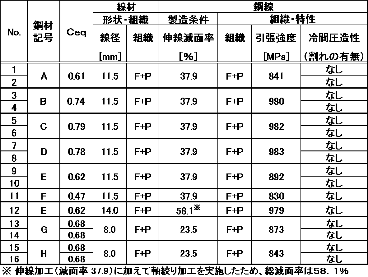
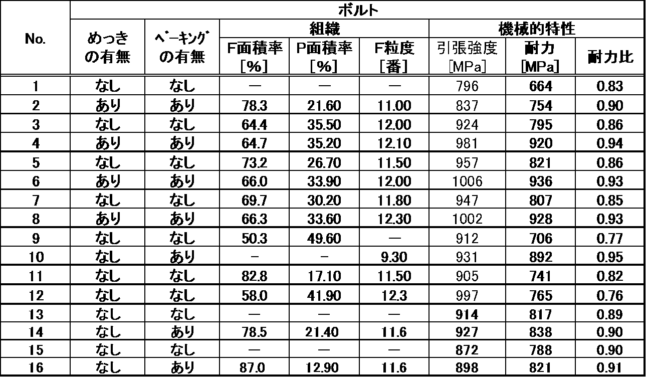
これらの結果から、次のように考察できる。No.1~8および13~16は本発明の実施形態で規定する要件を満足する発明例であり、本発明の実施形態に係る鋼線は優れた冷間圧造性を示し、かつ得られたボルトは、ブルーイング処理等の高温での熱処理を行わなくともブルーイング処理を必須としていた従来例であるNo.10に近いレベルの高い強度と耐力比を示し、かつ耐遅れ破壊性も備わっていることが分かる。特に、No.14および16は、所望の強度と、永久伸びの低減とを両立した優れた非調質ボルトであった。
これに対し、No.9、11および12は、本発明の実施形態で規定するいずれかの要件を満足しない例であり、いずれかの特性が劣化している。即ち、No.9は、C量が過剰であるため、熱間圧延前の加熱で未固溶炭化物が多く残り、フェライトを十分に確保できず、耐力比が小さくなった。No.11は、本発明の実施形態で積極的に使用しないVおよびNbを添加した例である。この様にVおよびNbを添加した場合、特性は確保できるが、製造段階における析出物形態の制御等が容易でない。またNo.12は、鋼材の成分組成および組織が規定範囲を外れており、ブルーイング等の熱処理なしでは、所望の耐力比が得られない比較例である。
本出願は、出願日が2016年3月31日である日本国特許出願、特願第2016-071429号、および、出願日が2017年2月24日である日本国特許出願、特願第2017-033373号を基礎出願とする優先権主張を伴う。特願第2016-071429号および特願第2017-033373号は参照することにより本明細書に取り込まれる。
Claims (6)
- 成分組成が、質量%で、
C:0.05~0.30%、
Si:1.10~2.5%、
Mn:0.50~2.5%、
P:0%超0.03%以下、
S:0%超0.03%以下、
Cr:0.03~0.30%、
Al:0.010~0.10%、および
N:0.0020~0.0100%
を満たし、残部が鉄および不可避的不純物からなり、下記式(1)で表される炭素当量Ceqが0.60以上0.80以下であり、
全組織に占めるフェライトの面積率が60%以上、かつ全組織に占めるパーライトの面積率が5%以上であり、更にフェライト結晶粒度番号が10番以上であることを特徴とする非調質ボルト用線材。
Ceq=[C]+[Si]/7+[Mn]/5+[Cr]/9…(1)
上記式(1)において、[元素]は鋼中の各元素の質量%での含有量を示す。 - 請求項1に記載の非調質ボルト用線材を製造する方法であって、
請求項1に記載の成分組成を満たす鋼材を用い、圧延時の加熱温度を1000℃以上1200℃以下、かつ熱間圧延後、800℃から500℃までの平均冷却速度を2.0~5.0℃/秒とすることを特徴とする非調質ボルト用線材の製造方法。 - 成分組成が、質量%で、
C:0.05~0.30%、
Si:1.10~2.5%、
Mn:0.50~2.5%、
P:0%超0.03%以下、
S:0%超0.03%以下、
Cr:0.03~0.30%、
Al:0.010~0.10%、および
N:0.0020~0.0100%
を満たし、残部が鉄および不可避的不純物からなり、下記式(1)で表される炭素当量Ceqが0.60以上0.80以下であり、
全組織に占めるフェライトの面積率が60%以上、かつ全組織に占めるパーライトの面積率が5%以上であり、更にフェライト結晶粒度番号が10番以上であることを特徴とする非調質ボルト用鋼線。
Ceq=[C]+[Si]/7+[Mn]/5+[Cr]/9…(1)
上記式(1)において、[元素]は鋼中の各元素の質量%での含有量を示す。 - 請求項3に記載の非調質ボルト用鋼線を製造する方法であって、
請求項1に記載の非調質ボルト用線材を用い、伸線減面率20~40%で伸線することを特徴とする非調質ボルト用鋼線の製造方法。 - 成分組成が、質量%で、
C:0.05~0.30%、
Si:1.10~2.5%、
Mn:0.50~2.5%、
P:0%超0.03%以下、
S:0%超0.03%以下、
Cr:0.03~0.30%、
Al:0.010~0.10%、および
N:0.0020~0.0100%
を満たし、残部が鉄および不可避的不純物からなり、下記式(1)で表される炭素当量Ceqが0.60以上0.80以下であり、
全組織に占めるフェライトの面積率が60%以上かつ全組織に占めるパーライトの面積率が5%以上であり、更に、フェライト結晶粒度番号が10番以上であることを特徴とする非調質ボルト。
Ceq=[C]+[Si]/7+[Mn]/5+[Cr]/9…(1)
上記式(1)において、[元素]は鋼中の各元素の質量%での含有量を示す。 - 引張強度が780MPa以上1200MPa以下であり、かつ耐力比が0.80以上である請求項5に記載の非調質ボルト。
Applications Claiming Priority (4)
| Application Number | Priority Date | Filing Date | Title |
|---|---|---|---|
| JP2016-071429 | 2016-03-31 | ||
| JP2016071429 | 2016-03-31 | ||
| JP2017-033373 | 2017-02-24 | ||
| JP2017033373A JP6758225B2 (ja) | 2016-03-31 | 2017-02-24 | 非調質ボルト用線材、非調質ボルト用鋼線およびそれらの製造方法、ならびに非調質ボルト |
Publications (1)
| Publication Number | Publication Date |
|---|---|
| WO2017170756A1 true WO2017170756A1 (ja) | 2017-10-05 |
Family
ID=59964658
Family Applications (1)
| Application Number | Title | Priority Date | Filing Date |
|---|---|---|---|
| PCT/JP2017/013035 Ceased WO2017170756A1 (ja) | 2016-03-31 | 2017-03-29 | 非調質ボルト用線材、非調質ボルト用鋼線およびそれらの製造方法、ならびに非調質ボルト |
Country Status (1)
| Country | Link |
|---|---|
| WO (1) | WO2017170756A1 (ja) |
Cited By (2)
| Publication number | Priority date | Publication date | Assignee | Title |
|---|---|---|---|---|
| CN110791708A (zh) * | 2019-11-06 | 2020-02-14 | 中天钢铁集团有限公司 | 一种汽车零部件用非调质钢及其生产工艺 |
| WO2025002361A1 (zh) * | 2023-06-30 | 2025-01-02 | 宝山钢铁股份有限公司 | 一种无镍免退火高强度耐候的螺栓用盘条、螺栓及其制造方法 |
Citations (7)
| Publication number | Priority date | Publication date | Assignee | Title |
|---|---|---|---|---|
| JPH01165721A (ja) * | 1987-12-21 | 1989-06-29 | Daido Steel Co Ltd | 非調質鋼ボルト用線材の製造方法 |
| JPH0967622A (ja) * | 1995-08-28 | 1997-03-11 | Kobe Steel Ltd | 冷間圧造性の優れた高強度非調質ボルト用鋼線の製造方法 |
| JPH09291312A (ja) * | 1996-04-26 | 1997-11-11 | Kobe Steel Ltd | 高強度非調質ボルト用線材の製法 |
| JP2002294401A (ja) * | 2001-03-28 | 2002-10-09 | Kobe Steel Ltd | 冷間加工性および熱処理後の強度安定性に優れた線状または棒状鋼およびその製造方法並びに機械部品 |
| JP2013501147A (ja) * | 2009-08-04 | 2013-01-10 | ポスコ | 高靭性非調質圧延鋼材及びその製造方法 |
| WO2013031640A1 (ja) * | 2011-08-26 | 2013-03-07 | 新日鐵住金株式会社 | 非調質機械部品用線材、非調質機械部品用鋼線、及び、非調質機械部品とそれらの製造方法 |
| WO2013051513A1 (ja) * | 2011-10-07 | 2013-04-11 | 株式会社神戸製鋼所 | ボルト用鋼線及びボルト、並びにその製造方法 |
-
2017
- 2017-03-29 WO PCT/JP2017/013035 patent/WO2017170756A1/ja not_active Ceased
Patent Citations (7)
| Publication number | Priority date | Publication date | Assignee | Title |
|---|---|---|---|---|
| JPH01165721A (ja) * | 1987-12-21 | 1989-06-29 | Daido Steel Co Ltd | 非調質鋼ボルト用線材の製造方法 |
| JPH0967622A (ja) * | 1995-08-28 | 1997-03-11 | Kobe Steel Ltd | 冷間圧造性の優れた高強度非調質ボルト用鋼線の製造方法 |
| JPH09291312A (ja) * | 1996-04-26 | 1997-11-11 | Kobe Steel Ltd | 高強度非調質ボルト用線材の製法 |
| JP2002294401A (ja) * | 2001-03-28 | 2002-10-09 | Kobe Steel Ltd | 冷間加工性および熱処理後の強度安定性に優れた線状または棒状鋼およびその製造方法並びに機械部品 |
| JP2013501147A (ja) * | 2009-08-04 | 2013-01-10 | ポスコ | 高靭性非調質圧延鋼材及びその製造方法 |
| WO2013031640A1 (ja) * | 2011-08-26 | 2013-03-07 | 新日鐵住金株式会社 | 非調質機械部品用線材、非調質機械部品用鋼線、及び、非調質機械部品とそれらの製造方法 |
| WO2013051513A1 (ja) * | 2011-10-07 | 2013-04-11 | 株式会社神戸製鋼所 | ボルト用鋼線及びボルト、並びにその製造方法 |
Cited By (2)
| Publication number | Priority date | Publication date | Assignee | Title |
|---|---|---|---|---|
| CN110791708A (zh) * | 2019-11-06 | 2020-02-14 | 中天钢铁集团有限公司 | 一种汽车零部件用非调质钢及其生产工艺 |
| WO2025002361A1 (zh) * | 2023-06-30 | 2025-01-02 | 宝山钢铁股份有限公司 | 一种无镍免退火高强度耐候的螺栓用盘条、螺栓及其制造方法 |
Similar Documents
| Publication | Publication Date | Title |
|---|---|---|
| US9835194B2 (en) | Steel wire for bolt, bolt, and manufacturing processes therefor | |
| JP4737319B2 (ja) | 加工性および耐疲労特性に優れた高強度合金化溶融亜鉛めっき鋼板およびその製造方法 | |
| US9970072B2 (en) | High-strength spring steel wire with excellent hydrogen embrittlement resistance, manufacturing process therefor, and high-strength spring | |
| JP5447741B1 (ja) | 鋼板、めっき鋼板、及びそれらの製造方法 | |
| JP5000367B2 (ja) | 耐水素脆化特性に優れた高強度亜鉛めっきボルト | |
| JPWO2019009410A1 (ja) | 熱延鋼板及びその製造方法 | |
| WO2017179372A1 (ja) | 高強度鋼板およびその製造方法 | |
| JP6687112B2 (ja) | 鋼線 | |
| CN105164299B (zh) | 抗拉强度为1180MPa以上的强度‑弯曲性平衡优异的熔融镀锌钢板或合金化熔融镀锌钢板 | |
| US20180066344A1 (en) | Wire rod for use in bolts that has excellent acid pickling properties and resistance to delayed fracture after quenching and tempering, and bolt | |
| JP6601284B2 (ja) | 高強度ボルト | |
| JP6461672B2 (ja) | 冷間圧造性、および焼入れ焼戻し後の耐遅れ破壊性に優れたボルト用鋼線、並びにボルト | |
| US20170219000A1 (en) | Steel for bolts, and bolt | |
| WO2015098531A1 (ja) | 高強度ばね用圧延材及びこれを用いた高強度ばね用ワイヤ | |
| JP2022540899A (ja) | 鋼部品の製造方法及び鋼部品 | |
| JP5459342B2 (ja) | 耐水素脆化特性に優れた高強度亜鉛めっきボルトの製造方法 | |
| WO2018061101A1 (ja) | 鋼 | |
| WO2013022010A1 (ja) | 溶融亜鉛めっき鋼板およびその製造方法 | |
| JP5434984B2 (ja) | 引張強度440MPa以上の加工性に優れた高強度溶融亜鉛めっき鋼板およびその製造方法 | |
| JP6758225B2 (ja) | 非調質ボルト用線材、非調質ボルト用鋼線およびそれらの製造方法、ならびに非調質ボルト | |
| US10487372B2 (en) | High-strength bolt | |
| WO2017170756A1 (ja) | 非調質ボルト用線材、非調質ボルト用鋼線およびそれらの製造方法、ならびに非調質ボルト | |
| JP6453140B2 (ja) | 切断端面の耐遅れ破壊性に優れた高強度鋼板およびその製造方法 | |
| JP4773106B2 (ja) | 強度−捻れ特性バランスに優れた鋼部品およびその製造方法と該鋼部品用鋼材 |
Legal Events
| Date | Code | Title | Description |
|---|---|---|---|
| NENP | Non-entry into the national phase |
Ref country code: DE |
|
| 121 | Ep: the epo has been informed by wipo that ep was designated in this application |
Ref document number: 17775290 Country of ref document: EP Kind code of ref document: A1 |
|
| 122 | Ep: pct application non-entry in european phase |
Ref document number: 17775290 Country of ref document: EP Kind code of ref document: A1 |