WO2017170307A1 - モータ用永久磁石およびモータ用永久磁石の製造方法 - Google Patents
モータ用永久磁石およびモータ用永久磁石の製造方法 Download PDFInfo
- Publication number
- WO2017170307A1 WO2017170307A1 PCT/JP2017/012215 JP2017012215W WO2017170307A1 WO 2017170307 A1 WO2017170307 A1 WO 2017170307A1 JP 2017012215 W JP2017012215 W JP 2017012215W WO 2017170307 A1 WO2017170307 A1 WO 2017170307A1
- Authority
- WO
- WIPO (PCT)
- Prior art keywords
- permanent magnet
- motor
- magnetic pole
- circumferential direction
- axial direction
- Prior art date
- Legal status (The legal status is an assumption and is not a legal conclusion. Google has not performed a legal analysis and makes no representation as to the accuracy of the status listed.)
- Ceased
Links
Images

Classifications
-
- H—ELECTRICITY
- H02—GENERATION; CONVERSION OR DISTRIBUTION OF ELECTRIC POWER
- H02K—DYNAMO-ELECTRIC MACHINES
- H02K1/00—Details of the magnetic circuit
- H02K1/06—Details of the magnetic circuit characterised by the shape, form or construction
- H02K1/22—Rotating parts of the magnetic circuit
- H02K1/27—Rotor cores with permanent magnets
-
- H—ELECTRICITY
- H02—GENERATION; CONVERSION OR DISTRIBUTION OF ELECTRIC POWER
- H02K—DYNAMO-ELECTRIC MACHINES
- H02K15/00—Processes or apparatus specially adapted for manufacturing, assembling, maintaining or repairing of dynamo-electric machines
- H02K15/02—Processes or apparatus specially adapted for manufacturing, assembling, maintaining or repairing of dynamo-electric machines of stator or rotor bodies
- H02K15/03—Processes or apparatus specially adapted for manufacturing, assembling, maintaining or repairing of dynamo-electric machines of stator or rotor bodies having permanent magnets
Definitions
- the present invention relates to a permanent magnet for a motor used in a three-phase motor driven by a 120 ° rectangular wave energization method.
- the present invention also relates to a method for manufacturing a permanent magnet for a motor used in a three-phase motor driven by a 120 ° rectangular wave energization method.
- a three-phase motor driven by a 120 ° rectangular wave energization method is known (see, for example, Patent Document 1).
- the three-phase motor described in Patent Document 1 is a DC brushless motor, and includes a rotor having a permanent magnet and a stator having a U-phase coil, a V-phase coil, and a W-phase coil.
- a magnet rotor used in a motor or the like is known (see, for example, Patent Document 2).
- N and S poles are alternately magnetized in the circumferential direction of the magnet rotor. Further, in this magnet rotor, the weld line formed at the time of manufacturing the magnet rotor and the boundary between the N pole and the S pole (boundary of the magnetic pole) substantially coincide.
- the torque ripple (the amount of torque fluctuation during motor rotation) is small in order to improve the motor characteristics.
- an object of the present invention is to provide a permanent magnet for a motor that can reduce torque ripple of the three-phase motor when used in a three-phase motor driven by a 120 ° rectangular wave energization method. It is in.
- Another object of the present invention is to provide a method of manufacturing a permanent magnet for a motor that can reduce torque ripple of the three-phase motor when used in a three-phase motor driven by a 120 ° rectangular wave energization method. Is to provide.
- the present inventor has made various studies.
- the inventors of the present application have made various studies by paying attention to the relationship between the position of the gate mark (gate mark) and weld line formed during the manufacture of the motor permanent magnet and the position of the magnetic pole of the motor permanent magnet. It was.
- the inventor of the present application will realize a three-phase motor driven by a 120 ° rectangular wave energization method if the position of the gate mark or weld line and the position of the magnetic pole of the permanent magnet for the motor satisfy a predetermined relationship. It came to know that the torque ripple of a three-phase motor can be reduced when a permanent magnet for a motor is used.
- the permanent magnet for a motor of the present invention is based on such new knowledge.
- N poles and S poles are alternately magnetized, and a plurality of gate traces arranged in an annular shape are formed on one end face of the motor permanent magnet in the axial direction of the motor permanent magnet,
- the boundary between the north and south poles in the circumferential direction is a magnetic pole boundary
- the center of the north and south poles in the circumferential direction is the magnetic pole center.
- Each of the circumferential centers of adjacent gate traces in the circumferential direction is disposed between the magnetic pole boundary and the magnetic pole center in the circumferential direction.
- the motor permanent magnet of the present invention when viewed from the axial direction, each of the circumferential centers of adjacent gate traces in the circumferential direction is disposed between the magnetic pole boundary and the magnetic pole center in the circumferential direction. ing. Therefore, the motor permanent magnet of the present invention can reduce torque ripple of the three-phase motor when used in a three-phase motor driven by a 120 ° rectangular wave energization method.
- gate traces twice as many as the number of magnetic poles of the permanent magnet for the motor are formed on one end face of the permanent magnet for the motor, and when viewed from the axial direction, Preferably, at least one of each of the plurality of magnetic pole centers is disposed at a position that coincides with the gate mark in the circumferential direction. In this case, when viewed from the axial direction, each of the plurality of magnetic pole boundaries and each of the plurality of magnetic pole centers are arranged at positions that coincide with each of the plurality of gate traces in the circumferential direction. It is more preferable. If comprised in this way, when the permanent magnet for motors is used for the three-phase motor driven by a 120 degrees rectangular wave electricity supply system, it will become possible to further reduce the torque ripple of this three-phase motor.
- each of the circumferential centers of adjacent gate traces in the circumferential direction is preferably a weld line.
- the method for manufacturing a permanent magnet for a motor of the present invention is a cylindrical motor permanent magnet used for a three-phase motor driven by a 120 ° rectangular wave energization method.
- the N pole in the circumferential direction when viewed from the axial direction of the permanent magnet for the motor
- the mold is formed from a plurality of gates arranged on one end side in the axial direction and arranged in an annular shape.
- Boundary and magnetic pole center Characterized in that it comprises a magnetizing step of magnetizing the magnet base material to be placed in each.
- each of the plurality of weld lines is disposed between the magnetic pole boundary and the magnetic pole center in the circumferential direction when viewed from the axial direction.
- the magnet base material is magnetized. Therefore, when the permanent magnet for a motor manufactured by the manufacturing method of the present invention is used for a three-phase motor driven by a 120 ° rectangular wave energization method, the torque ripple of the three-phase motor can be reduced. Become.
- the motor permanent magnet has twice as many weld lines as the number of magnetic poles of the motor permanent magnet.
- the weld line extends in the circumferential direction. It is preferable to magnetize the magnet base material so as to be arranged at the approximate center between the magnetic pole boundary and the magnetic pole center. If comprised in this way, when the permanent magnet for motors manufactured with this manufacturing method is used for the three-phase motor driven by a 120 degree rectangular wave energization system, the torque ripple of this three-phase motor will be reduced more. It becomes possible.
- the diameters of adjacent gates in the circumferential direction are different.
- the position of the weld line in the circumferential direction can be adjusted.
- the motor permanent magnet of the present invention can reduce the torque ripple of the three-phase motor when used in a three-phase motor driven by a 120 ° rectangular wave energization method. Further, when the motor permanent magnet manufactured by the method for manufacturing a motor permanent magnet according to the present invention is used in a three-phase motor driven by a 120 ° rectangular wave energization method, torque ripple of the three-phase motor is reduced. It becomes possible to do.
- FIG. 2 is an enlarged cross-sectional view for explaining the configuration of the EE cross section of FIG. 1.
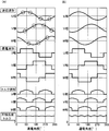
- A is a graph for demonstrating the simulation result of the torque ripple of the three-phase motor using the permanent magnet shown in FIG. 1
- B is the three-phase using the permanent magnet concerning a comparative example. It is a graph for demonstrating the simulation result of the torque ripple of a motor.
- FIG. 1 is a side view of a motor permanent magnet 1 according to an embodiment of the present invention.
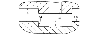
- FIG. 2 is an enlarged cross-sectional view for explaining the configuration of the EE cross section of FIG.
- the permanent magnet 1 for motors of this embodiment is a cylindrical magnet used for a three-phase motor (not shown).
- the permanent magnet 1 is a magnet used for a three-phase motor driven by a 120 ° rectangular wave energization method (rectangular wave drive).
- This three-phase motor is a DC brushless motor, and includes, for example, a rotor having permanent magnets 1 and a stator disposed on the outer peripheral side of the rotor. That is, this three-phase motor is an inner rotor type motor.
- the stator of this three-phase motor is provided with a U-phase coil, a V-phase coil, and a W-phase coil. In this three-phase motor, the energization state of the U-phase coil, V-phase coil, and W-phase coil can be switched. Done, the rotor rotates.
- Permanent magnet 1 is an anisotropic magnet.
- the permanent magnet 1 is formed in a thick cylindrical shape.
- the axial direction of the permanent magnet 1 formed in a cylindrical shape is referred to as “axial direction”
- the circumferential direction (circumferential direction) of the permanent magnet 1 is referred to as “circumferential direction”.
- the outer peripheral surface of the permanent magnet 1 is alternately magnetized with N and S poles in the circumferential direction.
- four poles are magnetized on the outer peripheral surface of the permanent magnet 1. That is, two N poles and two S poles are alternately magnetized on the outer peripheral surface of the permanent magnet 1.
- the magnetic pole boundary 1a When the boundary between the N pole and the S pole in the circumferential direction is the magnetic pole boundary 1a, and the center of the N pole and the center of the S pole in the circumferential direction (that is, the center of the magnetic pole) is the magnetic pole center 1b,
- the four magnetic pole boundaries 1a are disposed at a 90 ° pitch with respect to the center of the permanent magnet 1
- the four magnetic pole centers 1b are disposed at a 90 ° pitch with respect to the center of the permanent magnet 1.
- the four magnetic pole boundaries 1a and the four magnetic pole centers 1b are alternately arranged at a 45 ° pitch.
- a plurality of circular recesses 1 d that are recessed toward the other side in the axial direction are formed on one end surface (one end surface) 1 c of the permanent magnet 1 in the axial direction.
- eight concave portions 1 d arranged in an annular shape along the circumferential direction are formed on one end surface 1 c of the permanent magnet 1.
- the eight concave portions 1d are arranged at a constant pitch in the circumferential direction. That is, the eight recesses 1d are arranged at a 45 ° pitch with respect to the center of the permanent magnet 1 when viewed from the axial direction.
- the eight concave portions 1d formed on the one end surface 1c of the permanent magnet 1 are formed so as to be shifted toward the inner peripheral side of the permanent magnet 1 formed in a cylindrical shape. That is, the eight concave portions 1d are formed so as to approach the inner peripheral side from the center in the circumferential direction of the one end surface 1c of the permanent magnet 1 formed in a cylindrical shape.
- a gate mark (gate mark) 1e which is a mark of the gate 5a of the mold 5 used when the permanent magnet 1 is manufactured. That is, eight gate traces 1e arranged in an annular shape at a constant pitch along the circumferential direction are formed on one end face 1c of the permanent magnet 1. In addition, the number of gate traces 1 e that is twice the number of magnetic poles of the permanent magnet 1 is formed on one end surface 1 c of the permanent magnet 1.
- the gate trace 1e is formed, for example, in a substantially circular shape, and the surface of the gate trace 1e is a rough surface having a satin finish.
- Each of the eight gate traces 1e is arranged at a position that coincides with each of the four magnetic pole boundaries 1a or each of the four magnetic pole centers 1b in the circumferential direction when viewed from the axial direction. That is, when viewed from the axial direction, each of the four magnetic pole boundaries 1a and each of the four magnetic pole centers 1b are arranged at positions corresponding to the eight gate traces 1e in the circumferential direction. Yes.
- each of the circumferential centers of the gate traces 1e adjacent in the circumferential direction is the center between the magnetic pole boundary 1a and the magnetic pole center 1b in the circumferential direction (more specifically, Each of the magnetic pole boundary 1a and the magnetic pole center 1b adjacent to each other in the circumferential direction) and the circumferential center of the gate traces 1e adjacent to each other in the circumferential direction.
- Each is disposed between the magnetic pole boundary 1a and the magnetic pole center 1b in the circumferential direction.
- each of the eight weld lines 1f formed at the time of injection molding of the permanent magnet 1 is each in the circumferential direction between the magnetic pole boundary 1a and the magnetic pole center 1b. It is arranged at the approximate center. That is, when viewed from the axial direction, each of the eight weld lines 1f is disposed between the magnetic pole boundary 1a and the magnetic pole center 1b in the circumferential direction. In addition, the number of weld lines 1 f that is twice the number of magnetic poles of the permanent magnet 1 is formed in the permanent magnet 1. Further, in this embodiment, when viewed from the axial direction, the center of the gate mark 1e formed in a circular shape coincides with the magnetic pole boundary 1a or the magnetic pole center 1b in the circumferential direction.
- the permanent magnet 1 configured as described above is manufactured as follows, for example. First, material powder of the permanent magnet 1 is injected from eight gates 5a into a mold 5 and a mold (not shown) combined with the mold 5 to injection-mold a cylindrical magnet substrate (injection molding). Process). The eight gates 5a are arranged on one end side in the axial direction and arranged in an annular shape at a constant pitch along the circumferential direction. The eight gates 5a have the same diameter.
- the injection molding process is performed with a magnetic field molding machine. That is, the magnet substrate is injection molded in a magnetic field.
- the magnet base material is sintered and a predetermined process such as a demagnetization process is performed on the magnet base material, and then each of the plurality of weld lines 1f formed during the injection molding process is viewed from the axial direction.
- the magnet base material is magnetized so as to be disposed between the magnetic pole boundary 1a and the magnetic pole center 1b in the circumferential direction (magnetization step).
- the magnet base material is magnetized so that each of the eight weld lines 1f is disposed at the approximate center between the magnetic pole boundary 1a and the magnetic pole center 1b in the circumferential direction.
- FIG. 3A is a graph for explaining a simulation result of torque ripple of a three-phase motor in which the permanent magnet 1 shown in FIG. 1 is used.
- FIG. 3B is a graph showing a permanent magnet according to a comparative example. It is a graph for demonstrating the simulation result of the torque ripple of the used three-phase motor.
- the three-phase motor using the permanent magnet 1 shown in FIG. 1 when current is supplied to the U-phase coil, the V-phase coil, and the W-phase coil, as shown in the energization waveform of FIG.
- Each of the back electromotive waveform of the V phase coil and the W phase coil, the torque waveform of the U phase coil, the V phase coil and the W phase coil, and the combined torque of the three phases is as shown in FIG.
- the three-phase motor driven by the 120 ° rectangular wave energization method is one of the U-phase coil, V-phase coil, and W-phase coil. The two phase coils are sequentially energized.
- a comparative example in which four gate traces are formed on one end surface in the axial direction, and each of the four weld lines in the circumferential direction is aligned with the magnetic pole center 1b when viewed from the axial direction.
- a current is supplied to the U-phase coil, the V-phase coil, and the W-phase coil as shown in the energization waveform in FIG.
- the U-phase coil, the V-phase coil and the W-phase coil) the U-phase coil, the V-phase coil and the W-phase coil, and the U-phase coil, the V-phase coil and the W-phase coil.
- Each of the torque waveform of the W-phase coil and the three-phase combined torque is as shown in FIG.
- the permanent magnet according to the comparative example is formed in the same manner as the permanent magnet 1 except that the weld line is not arranged at the approximate center between the magnetic pole boundary 1a and the magnetic pole center 1b in the circumferential direction.
- the back electromotive waveforms of the phase coil, the V phase coil, and the W phase coil drop at a location corresponding to the weld line 1f (a location surrounded by a circle). That is, the counter electromotive waveforms of the U phase coil, the V phase coil, and the W phase coil drop on both sides of the peak of the counter electromotive waveform. Therefore, as can be seen from the graph of the three-phase combined torque, the torque ripple of the three-phase motor using the permanent magnet 1 is smaller than the torque ripple of the three-phase motor using the permanent magnet according to the comparative example.
- each of the eight gate traces 1e coincides with each of the four magnetic pole boundaries 1a or each of the four magnetic pole centers 1b in the circumferential direction when viewed from the axial direction.
- Each of the eight weld lines 1f is arranged at the approximate center between the magnetic pole boundary 1a and the magnetic pole center 1b in the circumferential direction. Therefore, in the three-phase motor in which the permanent magnet 1 of this embodiment is used, it is possible to reduce torque ripple as shown by the above simulation result. That is, in this embodiment, when the permanent magnet 1 is used in a three-phase motor driven by a 120 ° rectangular wave energization method, it is possible to reduce the torque ripple of this three-phase motor.
- the gate trace 1e when viewed from the axial direction, is arranged at a position that coincides with the magnetic pole boundary 1a or the magnetic pole center 1b in the circumferential direction.
- the circumferential center of the gate traces 1e adjacent to each other in the circumferential direction is disposed between the magnetic pole boundary 1a and the magnetic pole center 1b in the circumferential direction, and the weld line 1f has a magnetic pole boundary in the circumferential direction. If it is disposed between 1a and the magnetic pole center 1b, the gate trace 1e may be displaced from the magnetic pole boundary 1a or the magnetic pole center 1b in the circumferential direction when viewed from the axial direction, or in the circumferential direction. It may be shifted from the magnetic pole boundary 1a and the magnetic pole center 1b. In this case, the eight gate traces 1e may not be arranged at a constant pitch in the circumferential direction.
- the three-phase motor driven by the 120 ° rectangular wave energization method is better when the gate trace 1e is disposed at a position that coincides with the magnetic pole boundary 1a or the magnetic pole center 1b in the circumferential direction.
- the torque ripple of the three-phase motor can be further reduced.
- one weld line 1f is disposed between the magnetic pole boundary 1a and the magnetic pole center 1b in the circumferential direction.
- two or more magnetic lines are disposed between the magnetic pole boundary 1a and the magnetic pole center 1b in the circumferential direction.
- a weld line 1f may be arranged.
- the four magnetic poles are magnetized on the outer peripheral surface of the permanent magnet 1, but the number of magnetic poles magnetized on the outer peripheral surface of the permanent magnet 1 may be other than four.
- a number of gate traces 1 e corresponding to the number of magnetic poles magnetized on the permanent magnet 1 are formed on the permanent magnet 1.
- the number of gate traces 1 e that is twice the number of magnetic poles of the permanent magnet 1 is formed in the permanent magnet 1.
- the eight gates 5a have the same diameter, but the adjacent gates 5a may have different diameters in the circumferential direction. In this case, the position of the weld line 1f in the circumferential direction can be adjusted.
- the motor using the permanent magnet 1 is an inner rotor type motor. However, the motor using the permanent magnet 1 may be an outer rotor type motor.
Landscapes
- Engineering & Computer Science (AREA)
- Power Engineering (AREA)
- Manufacturing & Machinery (AREA)
- Permanent Field Magnets Of Synchronous Machinery (AREA)
Abstract
120°矩形波通電方式で駆動される三相モータに使用されたときに、この三相モータのトルクリップルを低減することが可能なモータ用永久磁石を提供する。120°矩形波通電方式で駆動される三相モータに使用される円筒状のモータ用永久磁石1では、モータ用永久磁石1の周方向において、N極とS極とが交互に着磁され、モータ用永久磁石1の軸方向におけるモータ用永久磁石1の一方の端面1cには、円環状に配列される複数のゲート跡1eが形成されている。軸方向から見たときの、周方向におけるN極とS極との境界を磁極境界1aとし、周方向におけるN極の中心およびS極の中心を磁極中心1bとすると、軸方向から見たときに、周方向で隣り合うゲート跡1e同士の周方向の中心のそれぞれは、周方向における磁極境界1aと磁極中心1bとの間のそれぞれに配置されている。
Description
本発明は、120°矩形波通電方式で駆動される三相モータに使用されるモータ用永久磁石に関する。また、本発明は、120°矩形波通電方式で駆動される三相モータに使用されるモータ用永久磁石の製造方法に関する。
従来、120°矩形波通電方式によって駆動される三相モータが知られている(たとえば、特許文献1参照)。特許文献1に記載の三相モータは、DCブラシレスモータであり、永久磁石を有するロータと、U相コイル、V相コイルおよびW相コイルを有するステータとを備えている。また、従来、モータ等で使用されるマグネットロータが知られている(たとえば、特許文献2参照)。特許文献2に記載のマグネットロータでは、マグネットロータの周方向においてN極とS極とが交互に着磁されている。また、このマグネットロータでは、マグネットロータの製造時に形成されるウェルドラインと、N極とS極との境目(磁極の境目)とがほぼ一致している。
特許文献1に記載された三相モータにおいて、モータの特性を高めるためには、トルクリップル(モータの回転時のトルクの変動量)は小さい方が好ましい。
そこで、本発明の課題は、120°矩形波通電方式で駆動される三相モータに使用されたときに、この三相モータのトルクリップルを低減することが可能なモータ用永久磁石を提供することにある。また、本発明の課題は、120°矩形波通電方式で駆動される三相モータに使用されたときに、この三相モータのトルクリップルを低減することが可能となるモータ用永久磁石の製造方法を提供することにある。
上記の課題を解決するため、本願発明者は、種々の検討を行った。特に本願発明者は、モータ用永久磁石の製造時に形成されるゲート跡(ゲート痕)やウェルドラインの位置と、モータ用永久磁石の磁極の位置との関係に着目して、種々の検討を行った。その結果、本願発明者は、ゲート跡やウェルドラインの位置とモータ用永久磁石の磁極の位置とが所定の関係を満足していれば、120°矩形波通電方式で駆動される三相モータにモータ用永久磁石が使用されたときの三相モータのトルクリップルを低減することが可能になることを知見するに至った。
本発明のモータ用永久磁石は、かかる新たな知見に基づくものであり、120°矩形波通電方式で駆動される三相モータに使用される円筒状のモータ用永久磁石において、モータ用永久磁石の周方向において、N極とS極とが交互に着磁され、モータ用永久磁石の軸方向におけるモータ用永久磁石の一方の端面には、円環状に配列される複数のゲート跡が形成され、軸方向から見たときの、周方向におけるN極とS極との境界を磁極境界とし、周方向におけるN極の中心およびS極の中心を磁極中心とすると、軸方向から見たときに、周方向で隣り合うゲート跡同士の周方向の中心のそれぞれは、周方向における磁極境界と磁極中心との間のそれぞれに配置されていることを特徴とする。
本発明のモータ用永久磁石では、軸方向から見たときに、周方向で隣り合うゲート跡同士の周方向の中心のそれぞれは、周方向における磁極境界と磁極中心との間のそれぞれに配置されている。そのため、本発明のモータ用永久磁石では、120°矩形波通電方式で駆動される三相モータに使用されたときに、この三相モータのトルクリップルを低減することが可能になる。
本発明において、モータ用永久磁石の一方の端面には、モータ用永久磁石の磁極数の2倍の数のゲート跡が形成され、軸方向から見たときに、複数の磁極境界のそれぞれ、および、複数の磁極中心のそれぞれの少なくともいずれか一方は、周方向においてゲート跡と一致する位置に配置されていることが好ましい。また、この場合には、軸方向から見たときに、複数の磁極境界のそれぞれ、および、複数の磁極中心のそれぞれは、周方向において複数のゲート跡のそれぞれと一致する位置に配置されていることがより好ましい。このように構成すると、120°矩形波通電方式で駆動される三相モータにモータ用永久磁石が使用されたときに、この三相モータのトルクリップルをより低減することが可能になる。
本発明において、軸方向から見たときに、周方向で隣り合うゲート跡同士の周方向の中心のそれぞれは、ウェルドラインであることが好ましい。
また、上述の新たな知見に基づいて、本発明のモータ用永久磁石の製造方法は、120°矩形波通電方式で駆動される三相モータに使用される円筒状のモータ用永久磁石であって、モータ用永久磁石の周方向においてN極とS極とが交互に着磁されるモータ用永久磁石の製造方法において、モータ用永久磁石の軸方向から見たときの、周方向におけるN極とS極との境界を磁極境界とし、周方向におけるN極の中心およびS極の中心を磁極中心とすると、軸方向の一端側に配置されるとともに円環状に配列される複数のゲートから金型内に材料粉を注入して円筒状の磁石基材を射出成形する射出成形工程と、射出成形工程時に形成された複数のウェルドラインのそれぞれが、軸方向から見たときに、周方向における磁極境界と磁極中心との間のそれぞれに配置されるように磁石基材を着磁する着磁工程とを備えることを特徴とする。
本発明のモータ用永久磁石の製造方法では、着磁工程において、複数のウェルドラインのそれぞれが、軸方向から見たときに、周方向における磁極境界と磁極中心との間のそれぞれに配置されるように磁石基材を着磁している。そのため、本発明の製造方法で製造されたモータ用永久磁石が、120°矩形波通電方式で駆動される三相モータに使用されると、この三相モータのトルクリップルを低減することが可能になる。
本発明において、モータ用永久磁石には、モータ用永久磁石の磁極数の2倍の数のウェルドラインが形成され、着磁工程では、軸方向から見たときに、ウェルドラインが、周方向において磁極境界と磁極中心との間の略中心に配置されるように磁石基材を着磁することが好ましい。このように構成すると、この製造方法で製造されたモータ用永久磁石が、120°矩形波通電方式で駆動される三相モータに使用されたときに、この三相モータのトルクリップルをより低減することが可能になる。
本発明において、たとえば、周方向で隣り合うゲートの径が異なっている。この場合には、周方向におけるウェルドラインの位置を調整することが可能になる。
以上のように、本発明のモータ用永久磁石では、120°矩形波通電方式で駆動される三相モータに使用されたときに、この三相モータのトルクリップルを低減することが可能になる。また、本発明のモータ用永久磁石の製造方法で製造されたモータ用永久磁石が、120°矩形波通電方式で駆動される三相モータに使用されると、この三相モータのトルクリップルを低減することが可能になる。
以下、図面を参照しながら、本発明の実施の形態を説明する。
(モータ用永久磁石の構成および製造方法)
図1は、本発明の実施の形態にかかるモータ用永久磁石1の側面図である。図2は、図1のE-E断面の構成を説明するための拡大断面図である。
図1は、本発明の実施の形態にかかるモータ用永久磁石1の側面図である。図2は、図1のE-E断面の構成を説明するための拡大断面図である。
本形態のモータ用永久磁石1(以下、「永久磁石1」とする)は、三相モータ(図示省略)に使用される円筒状の磁石である。具体的には、永久磁石1は、120°矩形波通電方式(矩形波駆動)で駆動される三相モータに使用される磁石である。この三相モータは、DCブラシレスモータであり、たとえば、永久磁石1を有するロータと、ロータの外周側に配置されるステータとを備えている。すなわち、この三相モータは、インナーロータ型のモータである。また、この三相モータのステータは、U相コイルとV相コイルとW相コイルとを備えており、この三相モータでは、U相コイル、V相コイルおよびW相コイルの通電状態の切替が行われて、ロータが回転する。
永久磁石1は、異方性磁石である。この永久磁石1は、肉厚の円筒状に形成されている。以下の説明では、円筒状に形成される永久磁石1の軸方向を「軸方向」とし、永久磁石1の周方向(円周方向)を「周方向」とする。
永久磁石1の外周面には、周方向においてN極とS極とが交互に着磁されている。本形態では、永久磁石1の外周面に4極の磁極が着磁されている。すなわち、永久磁石1の外周面には、2個のN極と2個のS極とが交互に着磁されている。周方向におけるN極とS極との境界を磁極境界1aとし、周方向におけるN極の中心およびS極の中心(すなわち、磁極の中心)を磁極中心1bとすると、軸方向から見たときに、永久磁石1の中心に対して90°ピッチで4個の磁極境界1aが配置され、永久磁石1の中心に対して90°ピッチで4個の磁極中心1bが配置されている。また、軸方向から見たときに、4個の磁極境界1aと4個の磁極中心1bとが45°ピッチで交互に配置されている。
軸方向における永久磁石1の一方の端面(一端面)1cには、軸方向の他方側に向かって窪む円形状の複数の凹部1dが形成されている。本形態では、周方向に沿って円環状に配列される8個の凹部1dが永久磁石1の一端面1cに形成されている。8個の凹部1dは、周方向において一定のピッチで配列されている。すなわち、8個の凹部1dは、軸方向から見たときに、永久磁石1の中心に対して45°ピッチで配列されている。また、永久磁石1の一端面1cに形成された8個の凹部1dは、円筒状に形成された永久磁石1の内周側にずれて形成されている。つまり、8個の凹部1dは、円筒状に形成された永久磁石1の一端面1cの周方向における中心から内周側に寄って形成されている。
凹部1dの底面の中心には、永久磁石1の製造時に使用される金型5のゲート5aの跡であるゲート跡(ゲート痕)1eが形成されている。すなわち、永久磁石1の一端面1cには、周方向に沿って一定のピッチで円環状に配列される8個のゲート跡1eが形成されている。また、永久磁石1の一端面1cには、永久磁石1の磁極数の2倍の数のゲート跡1eが形成されている。ゲート跡1eは、たとえば、円形の略平面状に形成されており、ゲート跡1eの表面は、梨地状をなす粗面となっている。
8個のゲート跡1eのそれぞれは、軸方向から見たときに、周方向において4個の磁極境界1aのそれぞれまたは4個の磁極中心1bのそれぞれと一致する位置に配置されている。すなわち、軸方向から見たときに、4個の磁極境界1aのそれぞれ、および、4個の磁極中心1bのそれぞれは、周方向において8個のゲート跡1eのそれぞれと一致する位置に配置されている。また、軸方向から見たときに、周方向で隣り合うゲート跡1e同士の周方向の中心のそれぞれは、周方向における磁極境界1aと磁極中心1bとの間の中心(より具体的には、周方向で隣り合う磁極境界1aと磁極中心1bとの周方向の中心)のそれぞれと、周方向において一致する位置に配置されており、周方向で隣り合うゲート跡1e同士の周方向の中心のそれぞれは、周方向における磁極境界1aと磁極中心1bとの間のそれぞれに配置されている。
そのため、本形態では、軸方向から見たときに、永久磁石1の射出成形時に形成される8個のウェルドライン1fのそれぞれが、周方向において磁極境界1aと磁極中心1bとの間のそれぞれの略中心に配置されている。すなわち、軸方向から見たときに、8個の複数のウェルドライン1fのそれぞれは、周方向における磁極境界1aと磁極中心1bとの間のそれぞれに配置されている。また、永久磁石1には、永久磁石1の磁極数の2倍の数のウェルドライン1fが形成されている。また、本形態では、軸方向から見たときに、円形状に形成されるゲート跡1eの中心が、周方向において磁極境界1aまたは磁極中心1bと一致している。
以上のように構成された永久磁石1は、たとえば、以下のように製造される。まず、金型5および金型5と組み合わされる金型(図示省略)の中に8個のゲート5aから永久磁石1の材料粉を注入して円筒状の磁石基材を射出成形する(射出成形工程)。8個のゲート5aは、軸方向の一端側に配置されるとともに周方向に沿って一定のピッチで円環状に配列されている。また、8個のゲート5aの径は、等しくなっている。射出成形工程は、磁場成形機で行われる。すなわち、磁石基材は、磁界中で射出成形される。
その後、磁石基材を焼結させるとともに、磁石基材に対して脱磁処理等の所定の処理を行った後、射出成形工程時に形成された複数のウェルドライン1fのそれぞれが、軸方向から見たときに、周方向における磁極境界1aと磁極中心1bとの間のそれぞれに配置されるように磁石基材を着磁する(着磁工程)。具体的には、8個のウェルドライン1fのそれぞれが、周方向において磁極境界1aと磁極中心1bとの間のそれぞれの略中心に配置されるように磁石基材を着磁する。
(トルクリップルのシミュレーション)
図3(A)は、図1に示す永久磁石1が使用された三相モータのトルクリップルのシミュレーション結果を説明するためのグラフであり、図3(B)は、比較例にかかる永久磁石が使用された三相モータのトルクリップルのシミュレーション結果を説明するためのグラフである。
図3(A)は、図1に示す永久磁石1が使用された三相モータのトルクリップルのシミュレーション結果を説明するためのグラフであり、図3(B)は、比較例にかかる永久磁石が使用された三相モータのトルクリップルのシミュレーション結果を説明するためのグラフである。
図1に示す永久磁石1が使用された三相モータにおいて、図3(A)の通電波形に示すように、U相コイル、V相コイルおよびW相コイルに電流を供給すると、U相コイル、V相コイルおよびW相コイルの逆起波形、U相コイル、V相コイルおよびW相コイルのトルク波形、および、三相の合成トルクのそれぞれは、図3(A)に示すようになる。なお、U相コイル、V相コイルおよびW相コイルの通電波形からわかるように、120°矩形波通電方式で駆動される三相モータでは、U相コイル、V相コイルおよびW相コイルのうちの2つの相のコイルが順次、通電状態になる。
また、軸方向の一端面に4個のゲート跡が形成されるとともに、軸方向から見たときに周方向において4個のウェルドラインのそれぞれが磁極中心1bと一致する位置に配置された比較例にかかる永久磁石が使用された三相モータにおいて、図3(B)の通電波形に示すように、U相コイル、V相コイルおよびW相コイルに電流を供給すると(すなわち、永久磁石1が使用された三相モータと同様にU相コイル、V相コイルおよびW相コイルに電流を供給すると)、U相コイル、V相コイルおよびW相コイルの逆起波形、U相コイル、V相コイルおよびW相コイルのトルク波形、および、三相の合成トルクのそれぞれは、図3(B)に示すようになる。なお、比較例にかかる永久磁石は、周方向においてウェルドラインが磁極境界1aと磁極中心1bとの間の略中心に配置されていない点を除いて、永久磁石1と同様に形成されている。
周方向において磁極中心1bと一致する位置にウェルドラインが配置されている比較例にかかる永久磁石が使用された三相モータでは、図3(B)に示すように、U相コイル、V相コイルおよびW相コイルの逆起波形がきれいな正弦波になる。一方、周方向における磁極境界1aと磁極中心1bとの間の略中心にウェルドライン1fが配置されている永久磁石1が使用された三相モータでは、図3(A)に示すように、U相コイル、V相コイルおよびW相コイルの逆起波形が、ウェルドライン1fに対応する箇所(丸で囲まれた箇所)で落ち込む。すなわち、U相コイル、V相コイルおよびW相コイルの逆起波形が、逆起波形のピークの両側で落ち込む。そのため、三相合成トルクのグラフからわかるように、永久磁石1が使用された三相モータのトルクリップルは、比較例にかかる永久磁石が使用された三相モータのトルクリップルよりも小さくなる。
(本形態の主な効果)
以上説明したように、本形態では、8個のゲート跡1eのそれぞれは、軸方向から見たときに、周方向において4個の磁極境界1aのそれぞれまたは4個の磁極中心1bのそれぞれと一致する位置に配置されており、8個のウェルドライン1fのそれぞれは、周方向において磁極境界1aと磁極中心1bとの間のそれぞれの略中心に配置されている。そのため、本形態の永久磁石1が使用される三相モータでは、上述のシミュレーション結果が示すように、トルクリップルを低減することが可能になる。すなわち、本形態では、120°矩形波通電方式で駆動される三相モータに永久磁石1が使用されたときに、この三相モータのトルクリップルを低減することが可能になる。
以上説明したように、本形態では、8個のゲート跡1eのそれぞれは、軸方向から見たときに、周方向において4個の磁極境界1aのそれぞれまたは4個の磁極中心1bのそれぞれと一致する位置に配置されており、8個のウェルドライン1fのそれぞれは、周方向において磁極境界1aと磁極中心1bとの間のそれぞれの略中心に配置されている。そのため、本形態の永久磁石1が使用される三相モータでは、上述のシミュレーション結果が示すように、トルクリップルを低減することが可能になる。すなわち、本形態では、120°矩形波通電方式で駆動される三相モータに永久磁石1が使用されたときに、この三相モータのトルクリップルを低減することが可能になる。
(他の実施の形態)
上述した形態は、本発明の好適な形態の一例ではあるが、これに限定されるものではなく本発明の要旨を変更しない範囲において種々変形実施が可能である。
上述した形態は、本発明の好適な形態の一例ではあるが、これに限定されるものではなく本発明の要旨を変更しない範囲において種々変形実施が可能である。
上述した形態では、軸方向から見たときに、ゲート跡1eは、周方向において磁極境界1aまたは磁極中心1bと一致する位置に配置されている。この他にもたとえば、周方向で隣り合うゲート跡1e同士の周方向の中心が、周方向における磁極境界1aと磁極中心1bとの間に配置されて、ウェルドライン1fが、周方向における磁極境界1aと磁極中心1bとの間に配置されるのであれば、ゲート跡1eは、軸方向から見たときに、周方向において磁極境界1aまたは磁極中心1bとずれていても良いし、周方向において磁極境界1aおよび磁極中心1bとずれていても良い。また、この場合には、8個のゲート跡1eは、周方向において一定のピッチで配置されていなくても良い。
ただし、軸方向から見たときに、周方向において磁極境界1aまたは磁極中心1bと一致する位置にゲート跡1eが配置されている方が、120°矩形波通電方式で駆動される三相モータにモータ用永久磁石1が使用されたときに、この三相モータのトルクリップルをより低減することが可能になる。
上述した形態では、周方向における磁極境界1aと磁極中心1bとの間に1個のウェルドライン1fが配置されているが、周方向における磁極境界1aと磁極中心1bとの間に2個以上のウェルドライン1fが配置されても良い。また、上述した形態では、永久磁石1の外周面に4極の磁極が着磁されているが、永久磁石1の外周面に着磁される磁極の数は4極以外であっても良い。この場合には、永久磁石1に着磁される磁極の数に応じた数のゲート跡1eが永久磁石1に形成される。たとえば、永久磁石1の磁極数の2倍の数のゲート跡1eが永久磁石1に形成される。
上述した形態では、8個のゲート5aの径は等しくなっているが、周方向で隣り合うゲート5aの径が異なっていても良い。この場合には、周方向におけるウェルドライン1fの位置を調整することが可能になる。また、上述した形態では、永久磁石1が使用されるモータは、インナーロータ型のモータであるが、永久磁石1が使用されるモータは、アウターロータ型のモータであっても良い。
1 永久磁石(モータ用永久磁石)
1a 磁極境界
1b 磁極中心
1c 一端面(一方の端面)
1e ゲート跡
1f ウェルドライン
5 金型
5a ゲート
1a 磁極境界
1b 磁極中心
1c 一端面(一方の端面)
1e ゲート跡
1f ウェルドライン
5 金型
5a ゲート
Claims (7)
- 120°矩形波通電方式で駆動される三相モータに使用される円筒状のモータ用永久磁石において、
前記モータ用永久磁石の周方向において、N極とS極とが交互に着磁され、
前記モータ用永久磁石の軸方向における前記モータ用永久磁石の一方の端面には、円環状に配列される複数のゲート跡が形成され、
前記軸方向から見たときの、前記周方向におけるN極とS極との境界を磁極境界とし、前記周方向におけるN極の中心およびS極の中心を磁極中心とすると、
前記軸方向から見たときに、前記周方向で隣り合う前記ゲート跡同士の前記周方向の中心のそれぞれは、前記周方向における前記磁極境界と前記磁極中心との間のそれぞれに配置されていることを特徴とするモータ用永久磁石。 - 前記モータ用永久磁石の一方の端面には、前記モータ用永久磁石の磁極数の2倍の数の前記ゲート跡が形成され、
前記軸方向から見たときに、複数の前記磁極境界のそれぞれ、および、複数の前記磁極中心のそれぞれの少なくともいずれか一方は、前記周方向において前記ゲート跡と一致する位置に配置されていることを特徴とする請求項1記載のモータ用永久磁石。 - 前記軸方向から見たときに、複数の前記磁極境界のそれぞれ、および、複数の前記磁極中心のそれぞれは、前記周方向において複数の前記ゲート跡のそれぞれと一致する位置に配置されていることを特徴とする請求項2記載のモータ用永久磁石。
- 前記軸方向から見たときに、前記周方向で隣り合う前記ゲート跡同士の前記周方向の中心のそれぞれは、ウェルドラインであることを特徴とする請求項1記載のモータ用永久磁石。
- 120°矩形波通電方式で駆動される三相モータに使用される円筒状のモータ用永久磁石であって、前記モータ用永久磁石の周方向においてN極とS極とが交互に着磁されるモータ用永久磁石の製造方法において、
前記モータ用永久磁石の軸方向から見たときの、前記周方向におけるN極とS極との境界を磁極境界とし、前記周方向におけるN極の中心およびS極の中心を磁極中心とすると、
前記軸方向の一端側に配置されるとともに円環状に配列される複数のゲートから金型内に材料粉を注入して円筒状の磁石基材を射出成形する射出成形工程と、
前記射出成形工程時に形成された複数のウェルドラインのそれぞれが、前記軸方向から見たときに、前記周方向における前記磁極境界と前記磁極中心との間のそれぞれに配置されるように前記磁石基材を着磁する着磁工程とを備えることを特徴とするモータ用永久磁石の製造方法。 - 前記モータ用永久磁石には、前記モータ用永久磁石の磁極数の2倍の数の前記ウェルドラインが形成され、
前記着磁工程では、前記軸方向から見たときに、前記ウェルドラインが、前記周方向において前記磁極境界と前記磁極中心との間の略中心に配置されるように前記磁石基材を着磁することを特徴とする請求項4記載のモータ用永久磁石の製造方法。 - 前記周方向で隣り合う前記ゲートの径が異なっていることを特徴とする請求項4または5記載のモータ用永久磁石の製造方法。
Priority Applications (1)
| Application Number | Priority Date | Filing Date | Title |
|---|---|---|---|
| CN201780020110.6A CN108886305A (zh) | 2016-03-30 | 2017-03-27 | 电动机用永久磁体及电动机用永久磁体的制造方法 |
Applications Claiming Priority (2)
| Application Number | Priority Date | Filing Date | Title |
|---|---|---|---|
| JP2016-067291 | 2016-03-30 | ||
| JP2016067291A JP2017184420A (ja) | 2016-03-30 | 2016-03-30 | モータ用永久磁石およびモータ用永久磁石の製造方法 |
Publications (1)
| Publication Number | Publication Date |
|---|---|
| WO2017170307A1 true WO2017170307A1 (ja) | 2017-10-05 |
Family
ID=59965509
Family Applications (1)
| Application Number | Title | Priority Date | Filing Date |
|---|---|---|---|
| PCT/JP2017/012215 Ceased WO2017170307A1 (ja) | 2016-03-30 | 2017-03-27 | モータ用永久磁石およびモータ用永久磁石の製造方法 |
Country Status (3)
| Country | Link |
|---|---|
| JP (1) | JP2017184420A (ja) |
| CN (1) | CN108886305A (ja) |
| WO (1) | WO2017170307A1 (ja) |
Citations (4)
| Publication number | Priority date | Publication date | Assignee | Title |
|---|---|---|---|---|
| JPS6251965U (ja) * | 1985-09-19 | 1987-03-31 | ||
| JP2004007998A (ja) * | 2003-09-04 | 2004-01-08 | Mitsubishi Electric Corp | マグネットロータ |
| JP2004064857A (ja) * | 2002-07-26 | 2004-02-26 | Asmo Co Ltd | ブラシレスモータ |
| JP2008172965A (ja) * | 2007-01-15 | 2008-07-24 | Matsushita Electric Ind Co Ltd | 永久磁石回転子及びモータ並びに電気機器 |
Family Cites Families (3)
| Publication number | Priority date | Publication date | Assignee | Title |
|---|---|---|---|---|
| JP4626382B2 (ja) * | 2005-04-28 | 2011-02-09 | 株式会社デンソー | 電動機 |
| JP5373882B2 (ja) * | 2011-12-21 | 2013-12-18 | 敏秀 北 | 電動モーター |
| US9742228B2 (en) * | 2013-10-18 | 2017-08-22 | General Electric Company | Torque ripple reduction in electric machines |
-
2016
- 2016-03-30 JP JP2016067291A patent/JP2017184420A/ja not_active Withdrawn
-
2017
- 2017-03-27 WO PCT/JP2017/012215 patent/WO2017170307A1/ja not_active Ceased
- 2017-03-27 CN CN201780020110.6A patent/CN108886305A/zh not_active Withdrawn
Patent Citations (4)
| Publication number | Priority date | Publication date | Assignee | Title |
|---|---|---|---|---|
| JPS6251965U (ja) * | 1985-09-19 | 1987-03-31 | ||
| JP2004064857A (ja) * | 2002-07-26 | 2004-02-26 | Asmo Co Ltd | ブラシレスモータ |
| JP2004007998A (ja) * | 2003-09-04 | 2004-01-08 | Mitsubishi Electric Corp | マグネットロータ |
| JP2008172965A (ja) * | 2007-01-15 | 2008-07-24 | Matsushita Electric Ind Co Ltd | 永久磁石回転子及びモータ並びに電気機器 |
Also Published As
| Publication number | Publication date |
|---|---|
| CN108886305A (zh) | 2018-11-23 |
| JP2017184420A (ja) | 2017-10-05 |
Similar Documents
| Publication | Publication Date | Title |
|---|---|---|
| CN103534900B (zh) | 永磁铁型旋转电机及其制造方法 | |
| US9780610B2 (en) | Rotor and motor | |
| US10714992B2 (en) | Motor including plurality of rotor parts | |
| JP2015133839A (ja) | 磁石埋込型ロータ | |
| JP2008245488A (ja) | リング状磁石及びその製造方法、並びにモータ | |
| US20130062985A1 (en) | Brushless dc motor | |
| JP2018143096A (ja) | ロータ、及びモータ | |
| JP6385854B2 (ja) | ブラシレスモータ | |
| KR20150109820A (ko) | Bldc 모터 | |
| US9819234B2 (en) | Method for operating variable magnetic flux motor | |
| JP2018182118A (ja) | 着磁装置、及び着磁方法 | |
| JP2016144322A (ja) | 回転電機用ロータおよびその製造方法 | |
| JP6544992B2 (ja) | 磁石およびマグネットロータ | |
| CN111869067A (zh) | 电动机 | |
| CN112823466B (zh) | 磁化装置、磁化方法以及马达的制造方法 | |
| US20170279340A1 (en) | Orientation magnetization device and magnet-embedded rotor | |
| KR100679804B1 (ko) | 모터의 회전자 | |
| WO2017170307A1 (ja) | モータ用永久磁石およびモータ用永久磁石の製造方法 | |
| WO2017010151A1 (ja) | 電機子、回転電機、クロスフローファン | |
| JP4569139B2 (ja) | Ipmモータ用ロータ、これを用いたipmモータ用ロータの製造方法、およびそのipmモータ。 | |
| JP2015029381A (ja) | ロータ及びモータ | |
| JP6338245B2 (ja) | マルチランデル型モータ | |
| JP2014100044A (ja) | 電動モータ | |
| CN115699543A (zh) | 转子的制造装置、转子的制造方法和转子 | |
| JP2009124007A (ja) | 永久磁石の着磁方法及び装置 |
Legal Events
| Date | Code | Title | Description |
|---|---|---|---|
| NENP | Non-entry into the national phase |
Ref country code: DE |
|
| 121 | Ep: the epo has been informed by wipo that ep was designated in this application |
Ref document number: 17774844 Country of ref document: EP Kind code of ref document: A1 |
|
| 122 | Ep: pct application non-entry in european phase |
Ref document number: 17774844 Country of ref document: EP Kind code of ref document: A1 |