WO2017170227A1 - 燃焼器、及びガスタービン - Google Patents
燃焼器、及びガスタービン Download PDFInfo
- Publication number
- WO2017170227A1 WO2017170227A1 PCT/JP2017/012018 JP2017012018W WO2017170227A1 WO 2017170227 A1 WO2017170227 A1 WO 2017170227A1 JP 2017012018 W JP2017012018 W JP 2017012018W WO 2017170227 A1 WO2017170227 A1 WO 2017170227A1
- Authority
- WO
- WIPO (PCT)
- Prior art keywords
- fuel
- combustor
- gas
- temperature
- combustion
- Prior art date
- Legal status (The legal status is an assumption and is not a legal conclusion. Google has not performed a legal analysis and makes no representation as to the accuracy of the status listed.)
- Ceased
Links
Images




Classifications
-
- F—MECHANICAL ENGINEERING; LIGHTING; HEATING; WEAPONS; BLASTING
- F02—COMBUSTION ENGINES; HOT-GAS OR COMBUSTION-PRODUCT ENGINE PLANTS
- F02C—GAS-TURBINE PLANTS; AIR INTAKES FOR JET-PROPULSION PLANTS; CONTROLLING FUEL SUPPLY IN AIR-BREATHING JET-PROPULSION PLANTS
- F02C7/00—Features, components parts, details or accessories, not provided for in, or of interest apart form groups F02C1/00 - F02C6/00; Air intakes for jet-propulsion plants
-
- F—MECHANICAL ENGINEERING; LIGHTING; HEATING; WEAPONS; BLASTING
- F02—COMBUSTION ENGINES; HOT-GAS OR COMBUSTION-PRODUCT ENGINE PLANTS
- F02C—GAS-TURBINE PLANTS; AIR INTAKES FOR JET-PROPULSION PLANTS; CONTROLLING FUEL SUPPLY IN AIR-BREATHING JET-PROPULSION PLANTS
- F02C7/00—Features, components parts, details or accessories, not provided for in, or of interest apart form groups F02C1/00 - F02C6/00; Air intakes for jet-propulsion plants
- F02C7/22—Fuel supply systems
- F02C7/232—Fuel valves; Draining valves or systems
-
- F—MECHANICAL ENGINEERING; LIGHTING; HEATING; WEAPONS; BLASTING
- F02—COMBUSTION ENGINES; HOT-GAS OR COMBUSTION-PRODUCT ENGINE PLANTS
- F02C—GAS-TURBINE PLANTS; AIR INTAKES FOR JET-PROPULSION PLANTS; CONTROLLING FUEL SUPPLY IN AIR-BREATHING JET-PROPULSION PLANTS
- F02C9/00—Controlling gas-turbine plants; Controlling fuel supply in air- breathing jet-propulsion plants
-
- F—MECHANICAL ENGINEERING; LIGHTING; HEATING; WEAPONS; BLASTING
- F02—COMBUSTION ENGINES; HOT-GAS OR COMBUSTION-PRODUCT ENGINE PLANTS
- F02C—GAS-TURBINE PLANTS; AIR INTAKES FOR JET-PROPULSION PLANTS; CONTROLLING FUEL SUPPLY IN AIR-BREATHING JET-PROPULSION PLANTS
- F02C9/00—Controlling gas-turbine plants; Controlling fuel supply in air- breathing jet-propulsion plants
- F02C9/26—Control of fuel supply
-
- F—MECHANICAL ENGINEERING; LIGHTING; HEATING; WEAPONS; BLASTING
- F02—COMBUSTION ENGINES; HOT-GAS OR COMBUSTION-PRODUCT ENGINE PLANTS
- F02C—GAS-TURBINE PLANTS; AIR INTAKES FOR JET-PROPULSION PLANTS; CONTROLLING FUEL SUPPLY IN AIR-BREATHING JET-PROPULSION PLANTS
- F02C9/00—Controlling gas-turbine plants; Controlling fuel supply in air- breathing jet-propulsion plants
- F02C9/26—Control of fuel supply
- F02C9/28—Regulating systems responsive to plant or ambient parameters, e.g. temperature, pressure, rotor speed
-
- F—MECHANICAL ENGINEERING; LIGHTING; HEATING; WEAPONS; BLASTING
- F02—COMBUSTION ENGINES; HOT-GAS OR COMBUSTION-PRODUCT ENGINE PLANTS
- F02C—GAS-TURBINE PLANTS; AIR INTAKES FOR JET-PROPULSION PLANTS; CONTROLLING FUEL SUPPLY IN AIR-BREATHING JET-PROPULSION PLANTS
- F02C9/00—Controlling gas-turbine plants; Controlling fuel supply in air- breathing jet-propulsion plants
- F02C9/26—Control of fuel supply
- F02C9/32—Control of fuel supply characterised by throttling of fuel
- F02C9/34—Joint control of separate flows to main and auxiliary burners
-
- F—MECHANICAL ENGINEERING; LIGHTING; HEATING; WEAPONS; BLASTING
- F23—COMBUSTION APPARATUS; COMBUSTION PROCESSES
- F23R—GENERATING COMBUSTION PRODUCTS OF HIGH PRESSURE OR HIGH VELOCITY, e.g. GAS-TURBINE COMBUSTION CHAMBERS
- F23R3/00—Continuous combustion chambers using liquid or gaseous fuel
- F23R3/02—Continuous combustion chambers using liquid or gaseous fuel characterised by the air-flow or gas-flow configuration
- F23R3/04—Air inlet arrangements
- F23R3/10—Air inlet arrangements for primary air
- F23R3/12—Air inlet arrangements for primary air inducing a vortex
- F23R3/14—Air inlet arrangements for primary air inducing a vortex by using swirl vanes
-
- F—MECHANICAL ENGINEERING; LIGHTING; HEATING; WEAPONS; BLASTING
- F23—COMBUSTION APPARATUS; COMBUSTION PROCESSES
- F23R—GENERATING COMBUSTION PRODUCTS OF HIGH PRESSURE OR HIGH VELOCITY, e.g. GAS-TURBINE COMBUSTION CHAMBERS
- F23R3/00—Continuous combustion chambers using liquid or gaseous fuel
- F23R3/02—Continuous combustion chambers using liquid or gaseous fuel characterised by the air-flow or gas-flow configuration
- F23R3/26—Controlling the air flow
-
- F—MECHANICAL ENGINEERING; LIGHTING; HEATING; WEAPONS; BLASTING
- F23—COMBUSTION APPARATUS; COMBUSTION PROCESSES
- F23R—GENERATING COMBUSTION PRODUCTS OF HIGH PRESSURE OR HIGH VELOCITY, e.g. GAS-TURBINE COMBUSTION CHAMBERS
- F23R3/00—Continuous combustion chambers using liquid or gaseous fuel
- F23R3/28—Continuous combustion chambers using liquid or gaseous fuel characterised by the fuel supply
-
- F—MECHANICAL ENGINEERING; LIGHTING; HEATING; WEAPONS; BLASTING
- F23—COMBUSTION APPARATUS; COMBUSTION PROCESSES
- F23R—GENERATING COMBUSTION PRODUCTS OF HIGH PRESSURE OR HIGH VELOCITY, e.g. GAS-TURBINE COMBUSTION CHAMBERS
- F23R3/00—Continuous combustion chambers using liquid or gaseous fuel
- F23R3/28—Continuous combustion chambers using liquid or gaseous fuel characterised by the fuel supply
- F23R3/286—Continuous combustion chambers using liquid or gaseous fuel characterised by the fuel supply having fuel-air premixing devices
-
- F—MECHANICAL ENGINEERING; LIGHTING; HEATING; WEAPONS; BLASTING
- F05—INDEXING SCHEMES RELATING TO ENGINES OR PUMPS IN VARIOUS SUBCLASSES OF CLASSES F01-F04
- F05D—INDEXING SCHEME FOR ASPECTS RELATING TO NON-POSITIVE-DISPLACEMENT MACHINES OR ENGINES, GAS-TURBINES OR JET-PROPULSION PLANTS
- F05D2270/00—Control
- F05D2270/30—Control parameters, e.g. input parameters
- F05D2270/303—Temperature
-
- F—MECHANICAL ENGINEERING; LIGHTING; HEATING; WEAPONS; BLASTING
- F23—COMBUSTION APPARATUS; COMBUSTION PROCESSES
- F23C—METHODS OR APPARATUS FOR COMBUSTION USING FLUID FUEL OR SOLID FUEL SUSPENDED IN A CARRIER GAS OR AIR
- F23C2900/00—Special features of, or arrangements for combustion apparatus using fluid fuels or solid fuels suspended in air; Combustion processes therefor
- F23C2900/07001—Air swirling vanes incorporating fuel injectors
Definitions
- the present invention relates to a combustor and a gas turbine.
- a gas turbine is driven by rotation by a compressor that compresses outside air to generate compressed air, a combustor that generates high-temperature and high-pressure combustion gas by burning fuel in the compressed air, and a combustion gas. And a turbine.
- a compressor that compresses outside air to generate compressed air
- a combustor that generates high-temperature and high-pressure combustion gas by burning fuel in the compressed air
- a combustion gas a combustion gas.
- a turbine In order to improve the efficiency of the gas turbine, it is necessary to increase the turbine inlet temperature, but there is a problem that NOx increases exponentially as the temperature increases.
- the combustor disclosed in Patent Document 1 below includes a burner that suppresses formation of a local high-temperature region by forming a uniform air-fuel mixture by swirling flow.
- the burner of this combustor includes a nozzle that is a shaft body extending along the burner axis, a burner cylinder that surrounds the outer periphery of the nozzle, and jets compressed air and fuel downstream, and fluid in the burner cylinder And swirl vanes that swirl around.
- An object of the present invention is to provide a combustor and a gas turbine that can prevent thermal damage to the combustor when abnormal combustion occurs.
- the combustor includes a shaft body that extends along the axis, and a fluid that projects from the outer peripheral surface of the shaft body in the radial direction of the axis and flows downstream in the axial direction.
- a nozzle body having a swirl vane that pivots about the axis, a first fuel flow path for supplying fuel to a first fuel injection hole formed in the nozzle body, and the first fuel injection hole in the nozzle body
- a second fuel passage for supplying fuel to a second fuel injection hole formed radially outward, and a first fuel passage provided in the first fuel passage for adjusting the flow rate of the fuel flowing through the first fuel passage.
- a flow rate of fuel flowing through the first fuel flow path when a temperature detected by the temperature sensor and a temperature detected by the temperature sensor satisfy a predetermined condition. Control the first regulating valve to reduce And a control unit that, the.
- the temperature sensor may be disposed at a tip portion of the shaft body. According to such a configuration, thermal damage to the nozzle body can be prevented when the vortex core flashback occurs.
- the first adjustment valve may be controlled so that the flow rate of the fuel flowing through the first fuel flow path decreases.
- a gas turbine includes a combustor according to any one of the first to third aspects, a compressor that compresses air and supplies the combustor with air. And a turbine driven by combustion gas formed by combustion of fuel in the combustor.
- a gas turbine includes a combustor according to the first aspect, a compressor that compresses air and supplies air to the combustor, and fuel in the combustor. And a turbine driven by combustion gas formed by the combustion of, and the temperature sensor detects an exhaust gas temperature of the turbine.
- thermal damage to the combustor can be prevented without providing an additional temperature sensor.
- the fuel injected from the first fuel injection hole is reduced, and the downstream side of the nozzle body is reduced.
- thermal damage to the combustor can be prevented.
- FIG. 5 is a cross-sectional view taken along the line VV in FIG. 4 and showing the arrangement of the gas fuel pipe and the oil fuel flow path. It is a flowchart explaining the control method of the combustor of 1st embodiment of this invention. It is sectional drawing of the burner of 2nd embodiment of this invention.
- FIG. 8 is a cross-sectional view taken along the line VIII-VIII in FIG. 7 and showing the arrangement of gas fuel pipes. It is sectional drawing of the burner of 3rd embodiment of this invention. It is a schematic diagram which shows the structure of the gas turbine of 4th embodiment of this invention.
- a gas turbine 1 according to a first embodiment of the present invention will be described in detail with reference to the drawings.
- the gas turbine 1 of the present embodiment generates a high-temperature and high-pressure combustion gas by compressing air A to generate compressed air and burning fuel F in the compressed air.
- the compressor 2 includes a compressor rotor 6 that rotates about a rotation axis Ar, and a compressor casing 7 that covers the compressor rotor 6 in a rotatable manner.
- the turbine 4 includes a turbine rotor 8 that rotates about a rotation axis Ar, and a turbine casing 9 that rotatably covers the turbine rotor 8.
- the rotation axis of the compressor rotor 6 and the rotation axis of the turbine rotor 8 are located on the same straight line.
- the compressor rotor 6 and the turbine rotor 8 are connected to each other to form a gas turbine rotor 10.
- the compressor casing 7 and the turbine casing 9 are connected to each other to form a gas turbine casing 11.
- a rotor of a generator GEN is connected to the gas turbine rotor 10.
- the combustor 3 is fixed to the gas turbine casing 11.
- the combustor 3 includes a combustion cylinder 13 (or a tail cylinder) that burns fuel F inside and sends combustion gas generated as a result of combustion of the fuel F to the turbine 4, and a combustion cylinder. 13 and a fuel ejector 14 for ejecting fuel F and air A.
- the combustor 3 according to the present embodiment is of a dual type capable of oiling in addition to gas burning.
- the fuel ejector 14 includes a pilot burner 15 that diffuses and burns the injected fuel, a main burner 16 (nozzle body) that premixes and burns the injected fuel, and the pilot burner 15 and the main burner 16.
- a burner holding cylinder 17 to be held and a control device 5 are provided.
- the pilot burner 15 is a pilot nozzle 19 that is a shaft body that extends in the axial direction Da around the combustor axis Ac, a pilot burner cylinder 18 that covers the outer periphery of the pilot nozzle 19, and compressed air A around the combustor axis Ac. And a plurality of swirl vanes 20 that swirl.
- one side of the axial direction Da which is the direction in which the combustor axis Ac extends, is defined as an upstream side (right side in FIG. 3), and the other side is defined as a downstream side (left side in FIG. 3).
- the combustor axis Ac is also the burner axis of the pilot burner 15.
- An injection hole is formed at the downstream end of the pilot nozzle 19.
- the plurality of swirl vanes 20 are provided on the upstream side of the position where the injection holes are formed.
- Each swirl vane 20 extends from the outer periphery of the pilot nozzle 19 in a direction including a radial component, and is connected to the inner peripheral surface of the pilot burner cylinder 18.
- the pilot burner cylinder 18 has a main body portion 21 located on the outer periphery of the pilot nozzle 19 and a cone portion 22 connected to the downstream side of the main body portion 21 and gradually increasing in diameter toward the downstream side.
- Compressed air A compressed by the compressor 2 flows into the pilot burner cylinder 18 from the upstream side.
- the pilot burner cylinder 18 ejects the fuel injected from the pilot nozzle 19 together with the compressed air A from its downstream end. This fuel diffuses and burns in the combustion cylinder 13.
- the plurality of main burners 16 are arranged side by side in the circumferential direction around the combustor axis Ac so as to surround the outer peripheral side of the pilot burner 15.
- the main burner 16 is a main nozzle 24 which is a shaft extending along a burner axis Ab parallel to the combustor axis Ac, a main burner cylinder 25 covering the outer periphery of the main nozzle 24, and compressed air with the burner axis Ab as a center. And a plurality of swirl vanes 26 that swirl A. Since the burner axis Ab of the main burner 16 is parallel to the combustor axis Ac, the axial direction related to the combustor axis Ac and the axial direction related to the burner axis Ab are the same direction.
- the upstream side in the axial direction with respect to the combustor axis line Ac is the upstream side in the axial direction with respect to the burner axis line Ab
- the downstream side in the axial direction with respect to the combustor axis line Ac is the downstream side in the axial direction with respect to the burner axis line Ab.
- An oil fuel injection hole 23 for injecting oil fuel is formed near the tip of the main nozzle 24.
- the plurality of swirl vanes 26 are provided at an intermediate portion in the axial direction Da of the main nozzle 24.
- the main burner cylinder 25 has a main body portion 27 located on the outer periphery of the main nozzle 24 and an extension portion 28 connected to the downstream side of the main body portion 27 and extending toward the downstream side.
- the plurality of swirl vanes 26 are connected to the inner peripheral surface of the main body 27 in the main burner cylinder 25.
- a plurality of gas fuel injection holes 38 for injecting gas fuel are formed in the plurality of swirl vanes 26. Oil fuel or gas fuel is supplied into the main nozzle 24, and gas fuel is supplied from the main nozzle 24 to the swirl vanes 26.
- Compressed air A compressed by the compressor 2 flows into the main burner cylinder 25 from the upstream side.
- the compressed air A and the gas fuel injected from the swirl vane 26 are mixed to form a premixed gas PM.
- the main burner cylinder 25 ejects the premixed gas PM from its downstream end.
- the fuel in the premixed gas PM is premixed and combusted in the combustion cylinder 13.
- the oil fuel is supplied to the compressed air A through the oil fuel injection hole 23.
- the burner holding cylinder 17 has a cylindrical shape around the combustor axis Ac and covers the outer peripheral side of the plurality of main burner cylinders 25.
- the combustion cylinder 13 has a cylindrical shape centering on the combustor axis line Ac, and a combustion portion 31 that forms a combustion region 30 in which fuel injected from the main burner 16 and the pilot burner 15 burns. And a combustion gas guide part 32 for guiding the combustion gas generated by the combustion in the combustion gas flow path of the turbine 4.
- the combustion gas guide part 32 of the combustion cylinder 13 is formed on the downstream side of the combustion part 31 of the combustion cylinder 13.
- each swirl vane 26 of the main burner 16 projects radially from the outer peripheral surface of the main nozzle 24 and is connected to the inner peripheral surface of the main burner cylinder 25.
- the swirl vane 26 is formed to swirl the fluid flowing downstream, around the burner axis Ab.
- a temperature sensor 33 is provided at the tip of the main nozzle 24.
- the temperature sensor 33 is connected to the control device 5. That is, the temperature of the tip of the main nozzle 24 measured by the temperature sensor 33 is transmitted to the control device 5.
- a thermocouple can be used as the temperature sensor 33.
- the temperature sensor 33 is not limited to a thermocouple, and other temperature measuring means can be employed.
- the swirl vane 26 includes a nozzle-side connection portion 34 connected to the outer peripheral surface of the main nozzle 24, and a profile portion 36 in which a smooth and continuous profile surface 37 is formed for swirling fluid around the burner axis Ab. ,have.
- the circumferential direction around the burner axis Ab is simply referred to as the circumferential direction Dc
- the radial direction Dr around the burner axis Ab is simply referred to as the radial direction Dr below.
- a plurality of gas fuel injection holes 38 for injecting the gas fuel F are formed in the swirl vane 26.
- the gas fuel injection holes 38 include a plurality of first gas fuel injection holes 38a (first fuel injection holes) disposed on the radially inner side and a plurality of gas fuel injection holes 38a disposed on the radially outer side than the first gas fuel injection holes 38a.
- a second gas fuel injection hole 38b (second fuel injection hole). That is, the first gas fuel injection hole 38a is disposed closer to the main nozzle 24 than the second gas fuel injection hole 38b.
- the number of second gas fuel injection holes 38b is preferably larger than the number of first gas fuel injection holes 38a. It is not necessary that all the second gas fuel injection holes 38b are disposed radially outside the first gas fuel injection holes 38a.
- the main burner 16 includes an oil fuel flow path 40 that injects oil fuel from the oil fuel injection hole 23 of the main nozzle 24, and a first gas fuel flow that injects gas fuel F from the first gas fuel injection hole 38 a of the swirl vane 26.
- the first gas fuel channel 41 is provided with a first adjustment valve 43 that adjusts the flow rate of the gas fuel F flowing through the first gas fuel channel 41.
- the second gas fuel passage 42 is provided with a second adjustment valve 44 that adjusts the flow rate of the gas fuel F flowing through the second gas fuel passage 42.
- the first adjustment valve 43 and the second adjustment valve 44 can be controlled by the control device 5.
- the control device 5 adjusts the flow rate of the gas fuel F using the first adjustment valve 43 and the second adjustment valve 44 based on the temperature of the tip of the main nozzle 24 measured by the temperature sensor 33.
- the oil fuel passage 40 is formed substantially at the center of the main nozzle 24.
- the first gas fuel flow channel 41 and the second gas fuel flow channel 42 are formed alternately at intervals in the circumferential direction on the radially outer side of the oil fuel flow channel 40.
- the arrangement of the oil fuel passage 40 and the gas fuel passages 41 and 42 is not limited to this.
- the compressor 2 sucks outside air and compresses it.
- the air compressed by the compressor 2 is guided into the main burner 16 and the pilot burner 15 of the combustor 3.
- the main burner 16 and the pilot burner 15 are supplied with fuel from a fuel supply source.
- the main burner 16 ejects a premixed gas PM premixed with fuel and air into the combustion section 31 of the combustion cylinder 13.
- the premixed gas PM is premixed and combusted in the combustion unit 31.
- the pilot burner 15 ejects fuel and air into the combustion part 31 of the combustion cylinder 13. This fuel is subjected to diffusion combustion or premixed combustion in the combustion section 31.
- the combustion mode can be arbitrarily changed by selecting the fuel ejection portion of the pilot burner 15.
- High-temperature and high-pressure combustion gas generated by the combustion of fuel in the combustion section 31 of the combustion cylinder 13 is guided into the combustion gas flow path of the turbine 4 by the combustion gas guide section 32 of the combustion cylinder 13 and rotates the turbine rotor 8.
- Air compressed by the compressor 2 is introduced into the main burner cylinder 25 from its upstream end. This air swirls around the burner axis Ab from a plurality of swirl vanes 26 in the main burner cylinder 25.
- the gas fuel is injected into the main burner cylinder 25 from the gas fuel injection holes 38 of the plurality of swirl vanes 26.
- the oil fuel F is injected into the main burner cylinder 25 from the oil fuel injection hole 23.
- the gas fuel F injected from the swirl vane 26 and the air A that flows downstream while swirling are premixed in the main burner cylinder 25 and then burned from the downstream end of the main burner cylinder 25 as a premixed gas PM. It is ejected into the cylinder 13.
- the gas fuel F injected into the main burner cylinder 25 from the gas fuel injection holes 38 of the plurality of swirl vanes 26 is promoted to be mixed with the air A by the swirl flow formed by the plurality of swirl vanes 26.
- the premixed gas PM is ejected into the combustion cylinder 13 while turning from the main burner cylinder 25, so that the flame holding effect of the premixed flame formed by the combustion of the premixed gas PM is enhanced.
- the control method of the combustor 3 of this embodiment is demonstrated.
- the temperature rise determination step S1 for determining whether or not the temperature at the tip of the main nozzle 24 has increased by 50 ° C. from the steady value, and the temperature at the tip of the main nozzle 24 is steady.
- a gas fuel shut-off step S2 that shuts off the gas fuel F flowing through the first gas fuel flow path 41 when the temperature rises by 50 ° C. above the value.
- the control device 5 monitors the temperature of the tip of the main nozzle 24 measured by the temperature sensor 33.
- the control device 5 determines whether or not the temperature at the tip of the main nozzle 24 has increased by 50 ° C. from the steady value.
- the steady value is a temperature value during normal operation of the gas turbine 1 and is set as appropriate according to the use of the gas turbine 1.
- the criterion of 50 ° C. used in the temperature rise determination step S1 can be changed as appropriate. That is, in the temperature rise determination step S1, it is determined whether or not the temperature at the tip of the main nozzle 24 measured by the temperature sensor 33 has risen more than a predetermined temperature from a steady value.
- the flame may go up due to the vortex core flashback.
- tip of the main nozzle 24 rises to 50 degreeC or more from a steady value, it transfers to gas fuel interruption
- the control device 5 operates the first adjustment valve 43 to shut off the gas fuel F flowing through the first gas fuel flow path 41. Thereby, the gas fuel F is not injected from the first gas fuel injection hole 38a.
- the control device 5 shuts off the first adjustment valve 43 and controls the second adjustment valve 44 to increase the flow rate of the gas fuel F flowing through the second gas fuel passage 42.
- the control device 5 operates the second adjustment valve 44 so that the total amount of the injected gas fuel F does not change before and after the gas fuel cutoff step S2.
- the flow rate of the gas fuel F may be reduced without blocking the gas fuel F flowing through the first gas fuel flow path 41. It is not always necessary to increase the gas fuel F flowing through the second gas fuel channel 42 after the gas fuel F flowing through the first gas fuel channel 41 is shut off.
- the fuel concentration around the vortex core of the vortex core flashback is lowered by blocking the gas fuel F supplied from the first gas fuel injection hole 38a arranged radially inside by the gas fuel cutoff step S2. .
- the control device 5 operates the first adjustment valve when the temperature at the tip of the main nozzle 24 recovers to a steady value, and the first gas fuel Gas fuel F is flowed through the channel 41.
- the fuel F injected from the first gas fuel injection hole 38a is reduced. Can do. As a result, the fuel concentration around the vortex core of the vortex core flashback can be immediately reduced to prevent thermal damage to the main nozzle 24.
- the gas fuel injection hole 38 for injecting the gas fuel F to the swirl vane 26 is formed, and the gas fuel F is injected into the main burner cylinder 25 from here.
- a member in which a gas fuel injection hole is separately formed may be provided instead of forming the gas fuel injection hole 38 in the swirl vane 26.
- the installation location of the temperature sensor 33 is not limited to the tip of the main nozzle 24 as long as the temperature on the downstream side of the swirl vane 26 can be measured. A plurality of temperature sensors 33 may be arranged.
- a combustor according to a second embodiment of the present invention will be described in detail with reference to the drawings.
- the combustor of this embodiment is of a gas-only firing method that uses only gaseous fuel.
- the main burner 16B of the present embodiment includes a first gas fuel channel 41B and a plurality of second gas fuel channels 42B.
- the first gas fuel channel 41B is disposed at the approximate center of the main nozzle 24B.
- the second gas fuel passages 42B are arranged at intervals in the circumferential direction on the radially outer side of the first gas fuel passages 41B.
- the first gas fuel flow path 41B is connected to a first gas fuel injection hole 38a disposed on the radially inner side of the swirl vane 26.
- the second gas fuel flow path 42B is connected to a second gas fuel injection hole 38b disposed radially outside the first gas fuel injection hole 38a.
- the structure of the main nozzle 24B can be simplified. As a result, the cost of the gas turbine 1 can be reduced.
- a combustor according to a third embodiment of the present invention will be described in detail with reference to the drawings.
- the combustor of this embodiment is of a gas-only firing method that uses only gaseous fuel.
- the main burner 16C of the present embodiment includes a first gas fuel channel 41C and a plurality of second gas fuel channels 42C. Similar to the combustor of the second embodiment, the first gas fuel passage 41C is disposed at the approximate center of the main nozzle 24C. The second gas fuel flow path 42C is disposed on the radially outer side of the first gas fuel flow path 41C with an interval in the circumferential direction.
- the first gas fuel channel 41C of the present embodiment is connected to a plurality of tip gas fuel injection holes 38C formed in the vicinity of the tip of the main nozzle 24C.
- the tip gas fuel injection hole 38C is formed so as to incline toward the downstream side as it goes radially outward.
- the second gas fuel passage 42C is connected to all the gas fuel injection holes 38 formed in the swirl vane 26.
- the gas fuel injection hole 38 is disposed on the radially outer side than the tip gas fuel injection hole 38C.
- the tip gas fuel injection hole 38C connected to the first gas fuel flow path 41C can be arranged more radially inward.
- the structure of the main nozzle 24C can be simplified. As a result, the cost of the gas turbine 1 can be reduced.
- a combustor according to a fourth embodiment of the present invention will be described in detail with reference to the drawings.
- the differences from the first embodiment will be mainly described, and the description of the same parts will be omitted.
- blade path temperature an exhaust gas temperature immediately after the final stage of the turbine 4
- a BPT sensor 45 is provided.
- a temperature sensor is not provided at the tip of the main nozzle 24 of the present embodiment.
- the control device 5 For the BPT sensor 45, for example, a thermocouple or the like is used.
- the blade path temperature measured by the BPT sensor 45 is transmitted to the control device 5.
- the control device 5 compares the blade path temperature at the time of measurement with the blade path temperature 60 seconds before the measurement every 10 seconds. It is determined whether there is a temperature difference of 2 ° C. or more.
- the control device 5 determines that abnormal combustion has occurred in the combustor 3 when the temperature difference occurs, and executes the gas fuel cutoff step S2.
- the gas fuel F injected from the first gas fuel injection hole 38a when the abnormal combustion occurs and the temperature detected by the BPT sensor 45 satisfies a predetermined condition, the gas fuel F injected from the first gas fuel injection hole 38a (see FIG. 4). The fuel concentration on the downstream side of the main nozzle 24 is immediately decreased to prevent thermal damage to the combustor 3.
- the thermal damage of the combustor 3 is prevented without providing a temperature sensor at the tip of the main nozzle 24.
- the configuration of the main burner 16 of the present embodiment is not limited to the configuration of the main burner 16 of the first embodiment, and the configuration of the main burner 16 of the second embodiment and the third embodiment may be adopted. it can.
- the fuel injected from the first fuel injection hole is reduced, and the downstream side of the nozzle body is reduced.
- thermal damage to the combustor can be prevented.
Landscapes
- Engineering & Computer Science (AREA)
- Chemical & Material Sciences (AREA)
- Combustion & Propulsion (AREA)
- Mechanical Engineering (AREA)
- General Engineering & Computer Science (AREA)
- Control Of Combustion (AREA)
- Regulation And Control Of Combustion (AREA)
Abstract
軸線に沿って延びる軸体(24)、及び、軸体(24)の外周面から軸線の径方向に張り出して、軸線方向の下流側に流れる流体を軸線回りに旋回させる旋回羽根(26)を有するノズル本体(16)と、ノズル本体(16)に形成された第一燃料噴射孔(38a)に燃料を供給する第一燃料流路(41)と、ノズル本体(16)における第一燃料噴射孔(38a)よりも径方向外側に形成された第二燃料噴射孔(38b)に燃料を供給する第二燃料流路(42)と、第一燃料流路(41)に設けられて第一燃料流路(41)を流れる燃料の流量を調整する第一調整弁(43)と、旋回羽根(26)よりも下流側の温度を検出する温度センサ(33)と、温度センサ(33)が検出する温度が予め定めた条件を満たした場合に、第一燃料流路(41)を流れる燃料の流量が減少するように第一調整弁(43)を制御する制御装置(5)と、を備える燃焼器を提供する。
Description
本発明は、燃焼器、及びガスタービンに関する。
本願は、2016年3月30日に日本に出願された特願2016-69384号について優先権を主張し、その内容をここに援用する。
本願は、2016年3月30日に日本に出願された特願2016-69384号について優先権を主張し、その内容をここに援用する。
一般的に、ガスタービンは、外気を圧縮して圧縮空気を生成する圧縮機と、燃料を圧縮空気中で燃焼させることで高温高圧の燃焼ガスを生成する燃焼器と、燃焼ガスによって回転駆動されるタービンと、を備えている。
ガスタービンの効率向上のためにはタービン入口温度の上昇が必要であるが、温度上昇に伴いNOxが指数関数的に増加するという課題がある。NOxの増加に対する対策として、例えば、以下の特許文献1に開示されている燃焼器は、旋回流によって均一混合気を形成して局所的な高温領域の形成を抑制するバーナを備えている。
この燃焼器のバーナは、バーナ軸線に沿って延びる軸体であるノズルと、このノズルの外周を囲み、圧縮空気と燃料とを下流側に噴出するバーナ筒と、バーナ筒内の流体をバーナ軸線周りに旋回させる旋回羽根と、を備えている。
ガスタービンの効率向上のためにはタービン入口温度の上昇が必要であるが、温度上昇に伴いNOxが指数関数的に増加するという課題がある。NOxの増加に対する対策として、例えば、以下の特許文献1に開示されている燃焼器は、旋回流によって均一混合気を形成して局所的な高温領域の形成を抑制するバーナを備えている。
この燃焼器のバーナは、バーナ軸線に沿って延びる軸体であるノズルと、このノズルの外周を囲み、圧縮空気と燃料とを下流側に噴出するバーナ筒と、バーナ筒内の流体をバーナ軸線周りに旋回させる旋回羽根と、を備えている。
旋回が加えられた予混合気が燃焼する際、旋回流中心を火炎が遡上する現象(渦芯フラッシュバック)がしばしば生じることが知られている。渦芯フラッシュバックなどの異常燃焼が発生すると、ノズルに火炎が付着し、熱損傷する恐れがあるため、この発生を抑えることが望まれている。
この発明は、異常燃焼が発生した場合に燃焼器の熱損傷を防ぐことができる燃焼器、及びガスタービンを提供することを目的とする。
本発明の第一の態様によれば、燃焼器は、軸線に沿って延びる軸体、及び、前記軸体の外周面から前記軸線の径方向に張り出して、前記軸線方向の下流側に流れる流体を前記軸線回りに旋回させる旋回羽根を有するノズル本体と、前記ノズル本体に形成された第一燃料噴射孔に燃料を供給する第一燃料流路と、前記ノズル本体における前記第一燃料噴射孔よりも径方向外側に形成された第二燃料噴射孔に燃料を供給する第二燃料流路と、前記第一燃料流路に設けられて前記第一燃料流路を流れる燃料の流量を調整する第一調整弁と、前記旋回羽根よりも下流側の温度を検出する温度センサと、前記温度センサが検出する温度が予め定めた条件を満たした場合に、前記第一燃料流路を流れる燃料の流量が減少するように前記第一調整弁を制御する制御装置と、を備える。
このような構成によれば、異常燃焼が発生して温度センサが検出する温度が予め定めた条件を満たした場合に、第一燃料噴射孔から噴射される燃料を減少させて、ノズル本体の下流側の燃料濃度を即座に低下させることによって、燃焼器の熱損傷を防ぐことができる。
本発明の第二の態様によれば、上記第一の態様に係わる燃焼器において、前記温度センサは、前記軸体の先端部に配置されてよい。
このような構成によれば、渦芯フラッシュバックの発生時において、ノズル本体の熱損傷を防ぐことができる。
このような構成によれば、渦芯フラッシュバックの発生時において、ノズル本体の熱損傷を防ぐことができる。
本発明の第三の態様によれば、上記第二の態様に係わる燃焼器において、前記制御装置は、前記温度センサによって検出された温度が定常値から予め定められた温度より大きく上昇した場合に、前記第一燃料流路を流れる燃料の流量が減少するように前記第一調整弁を制御してよい。
本発明の第四の態様によれば、ガスタービンは、上記第一から第三の態様のいずれか一態様に係わる燃焼器と、空気を圧縮して前記燃焼器に空気を供給する圧縮機と、前記燃焼器内での燃料の燃焼で形成された燃焼ガスにより駆動するタービンと、を備えている。
本発明の第五の態様によれば、ガスタービンは、上記第一の態様に係わる燃焼器と、空気を圧縮して前記燃焼器に空気を供給する圧縮機と、前記燃焼器内での燃料の燃焼で形成された燃焼ガスにより駆動するタービンと、を備え、前記温度センサは、前記タービンの排気ガス温度を検知する。
このような構成によれば、タービンの排気ガス温度を検知する温度センサを備える既存のガスタービンにおいて、追加の温度センサを設けることなく、燃焼器の熱損傷を防ぐことができる。
本発明によれば、異常燃焼が発生して温度センサが検出する温度が予め定めた条件を満たした場合に、第一燃料噴射孔から噴射される燃料を減少させて、ノズル本体の下流側の燃料濃度を即座に低下させることによって、燃焼器の熱損傷を防ぐことができる。
〔第一の実施形態〕
本発明の第一の実施形態のガスタービン1について図面を参照して詳細に説明する。
図1に示すように、本実施形態のガスタービン1は、空気Aを圧縮して圧縮空気を生成する圧縮機2と、燃料Fを圧縮空気中で燃焼させることで高温高圧の燃焼ガスを生成する複数の燃焼器3と、燃焼ガスによって回転駆動されるタービン4と、を備えている。
本発明の第一の実施形態のガスタービン1について図面を参照して詳細に説明する。
図1に示すように、本実施形態のガスタービン1は、空気Aを圧縮して圧縮空気を生成する圧縮機2と、燃料Fを圧縮空気中で燃焼させることで高温高圧の燃焼ガスを生成する複数の燃焼器3と、燃焼ガスによって回転駆動されるタービン4と、を備えている。
圧縮機2は、回転軸線Arを中心として回転する圧縮機ロータ6と、圧縮機ロータ6を回転可能に覆う圧縮機ケーシング7と、を有している。タービン4は、回転軸線Arを中心として回転するタービンロータ8と、タービンロータ8を回転可能に覆うタービンケーシング9と、を有している。
圧縮機ロータ6の回転軸線とタービンロータ8の回転軸線とは、同一直線上に位置している。圧縮機ロータ6とタービンロータ8とは、互いに連結されてガスタービンロータ10を成している。圧縮機ケーシング7とタービンケーシング9とは、互いに連結されてガスタービンケーシング11を成している。
圧縮機ロータ6の回転軸線とタービンロータ8の回転軸線とは、同一直線上に位置している。圧縮機ロータ6とタービンロータ8とは、互いに連結されてガスタービンロータ10を成している。圧縮機ケーシング7とタービンケーシング9とは、互いに連結されてガスタービンケーシング11を成している。
ガスタービンロータ10には、例えば、発電機GENのロータが連結されている。ガスタービンケーシング11には、燃焼器3が固定されている。
図2に示すように、燃焼器3は、内部で燃料Fが燃焼して、この燃料Fの燃焼の結果生成される燃焼ガスをタービン4に送る燃焼筒13(又は尾筒)と、燃焼筒13内に燃料F及び空気Aを噴出する燃料噴出器14と、を有する。本実施形態の燃焼器3は、ガス焚きのほかに油焚きが可能なデュアル方式のものである。
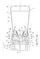
図3に示すように、燃料噴出器14は、噴出した燃料を拡散燃焼させるパイロットバーナ15と、噴出した燃料を予混合燃焼させるメインバーナ16(ノズル本体)と、パイロットバーナ15及びメインバーナ16を保持するバーナ保持筒17と、制御装置5と、を備えている。
パイロットバーナ15は、燃焼器軸線Acを中心として軸線方向Daに延びる軸体であるパイロットノズル19と、このパイロットノズル19の外周を覆うパイロットバーナ筒18と、燃焼器軸線Acを中心として圧縮空気Aを旋回させる複数の旋回羽根20と、を有する。ここで、燃焼器軸線Acが延びている方向である軸線方向Daの一方側を上流側(図3の右側)、他方側を下流側(図3の左側)とする。燃焼器軸線Acは、このパイロットバーナ15のバーナ軸線でもある。
パイロットノズル19の下流側端部には、噴射孔が形成されている。複数の旋回羽根20は、噴射孔が形成されている位置よりも上流側に設けられている。各々の旋回羽根20は、パイロットノズル19の外周から放射方向成分を含む方向に延びて、パイロットバーナ筒18の内周面に接続されている。
パイロットバーナ筒18は、パイロットノズル19の外周に位置する本体部21と、本体部21の下流側に接続され下流側向かって次第に拡径されているコーン部22と、を有している。パイロットバーナ筒18内には、その上流側から圧縮機2で圧縮された圧縮空気Aが流入する。パイロットバーナ筒18は、その下流端から、圧縮空気Aと共に、パイロットノズル19から噴射された燃料を噴出する。この燃料は、燃焼筒13内で拡散燃焼する。
パイロットバーナ筒18は、パイロットノズル19の外周に位置する本体部21と、本体部21の下流側に接続され下流側向かって次第に拡径されているコーン部22と、を有している。パイロットバーナ筒18内には、その上流側から圧縮機2で圧縮された圧縮空気Aが流入する。パイロットバーナ筒18は、その下流端から、圧縮空気Aと共に、パイロットノズル19から噴射された燃料を噴出する。この燃料は、燃焼筒13内で拡散燃焼する。
複数のメインバーナ16は、パイロットバーナ15の外周側を囲むよう、燃焼器軸線Acを中心として、周方向に並んで配置されている。
メインバーナ16は、燃焼器軸線Acと平行なバーナ軸線Abに沿って延びる軸体であるメインノズル24と、このメインノズル24の外周を覆うメインバーナ筒25と、バーナ軸線Abを中心として圧縮空気Aを旋回させる複数の旋回羽根26と、を有している。
メインバーナ16のバーナ軸線Abは、燃焼器軸線Acと平行であるため、燃焼器軸線Acに関する軸線方向と、バーナ軸線Abに関する軸線方向とは同じ方向である。燃焼器軸線Acに関する軸線方向の上流側は、バーナ軸線Abに関する軸線方向の上流側であり、燃焼器軸線Acに関する軸線方向の下流側は、バーナ軸線Abに関する軸線方向の下流側である。
メインノズル24の先端近傍には油燃料を噴射するための油燃料噴射孔23が形成されている。
メインバーナ16のバーナ軸線Abは、燃焼器軸線Acと平行であるため、燃焼器軸線Acに関する軸線方向と、バーナ軸線Abに関する軸線方向とは同じ方向である。燃焼器軸線Acに関する軸線方向の上流側は、バーナ軸線Abに関する軸線方向の上流側であり、燃焼器軸線Acに関する軸線方向の下流側は、バーナ軸線Abに関する軸線方向の下流側である。
メインノズル24の先端近傍には油燃料を噴射するための油燃料噴射孔23が形成されている。
複数の旋回羽根26は、メインノズル24の軸線方向Daにおける中間部に設けられている。メインバーナ筒25は、メインノズル24の外周に位置する本体部27と、本体部27の下流側に接続され下流側向かって延びる延長部28と、を有している。
複数の旋回羽根26は、メインバーナ筒25における本体部27の内周面に接続されている。複数の旋回羽根26には、ガス燃料を噴射するための複数のガス燃料噴射孔38(図4参照)が形成されている。メインノズル24内には、油燃料又はガス燃料が供給され、メインノズル24から旋回羽根26にガス燃料が供給される。
複数の旋回羽根26は、メインバーナ筒25における本体部27の内周面に接続されている。複数の旋回羽根26には、ガス燃料を噴射するための複数のガス燃料噴射孔38(図4参照)が形成されている。メインノズル24内には、油燃料又はガス燃料が供給され、メインノズル24から旋回羽根26にガス燃料が供給される。
メインバーナ筒25内には、その上流側から圧縮機2で圧縮された圧縮空気Aが流入する。メインバーナ筒25内では、この圧縮空気Aと旋回羽根26から噴射されたガス燃料とが混合して、予混合気体PMが形成される。メインバーナ筒25は、その下流端から予混合気体PMを噴出する。この予混合気体PM中の燃料は、燃焼筒13内で予混合燃焼する。
油焚き運転の際は、油燃料噴射孔23を介して圧縮空気Aに油燃料が供給される。
油焚き運転の際は、油燃料噴射孔23を介して圧縮空気Aに油燃料が供給される。
バーナ保持筒17は、燃焼器軸線Acを中心として円筒状を成し、複数のメインバーナ筒25の外周側を覆う。
燃焼筒13は、燃焼器軸線Acを中心として円筒状を成し、メインバーナ16及びパイロットバーナ15から噴出した燃料が燃焼する燃焼領域30を形成する燃焼部31と、筒状を成し、燃料の燃焼で生成された燃焼ガスをタービン4の燃焼ガス流路内に導く燃焼ガス案内部32と、を有する。燃焼筒13の燃焼ガス案内部32は、燃焼筒13の燃焼部31の下流側に形成されている。
図4に示すように、メインバーナ16の各々の旋回羽根26は、メインノズル24の外周面から径方向に張り出して、メインバーナ筒25の内周面に接続されている。旋回羽根26は、下流側に流通する流体をバーナ軸線Ab回りに旋回させるように形成されている。
メインノズル24の先端部には、温度センサ33が設けられている。温度センサ33は、制御装置5と接続されている。即ち、温度センサ33によって測定されたメインノズル24の先端の温度は、制御装置5に送信される。
温度センサ33としては、例えば、熱電対を使用することができる。温度センサ33としては、熱電対に限ることはなく、他の温度測定手段を採用可能である。
温度センサ33としては、例えば、熱電対を使用することができる。温度センサ33としては、熱電対に限ることはなく、他の温度測定手段を採用可能である。
旋回羽根26は、メインノズル24の外周面に接続されているノズル側接続部34と、流体をバーナ軸線Ab周りに旋回させるために滑らかで連続したプロファイル面37が形成されているプロファイル部36と、を有している。バーナ軸線Abを中心とした周方向を以下では単に周方向Dcとし、バーナ軸線Abを中心とした径方向Drを以下では単に径方向Drとする。
旋回羽根26には、ガス燃料Fを噴射する複数のガス燃料噴射孔38が形成されている。ガス燃料噴射孔38は、径方向内側に配置された複数の第一ガス燃料噴射孔38a(第一燃料噴射孔)と、第一ガス燃料噴射孔38aよりも径方向外側に配置された複数の第二ガス燃料噴射孔38b(第二燃料噴射孔)と、を有している。即ち、第一ガス燃料噴射孔38aは、第二ガス燃料噴射孔38bよりもメインノズル24側に配置されている。
第二ガス燃料噴射孔38bの数は、第一ガス燃料噴射孔38aの数よりも多いことが好ましい。全ての第二ガス燃料噴射孔38bが、第一ガス燃料噴射孔38aよりも径方向外側に配置されている必要はない。
第二ガス燃料噴射孔38bの数は、第一ガス燃料噴射孔38aの数よりも多いことが好ましい。全ての第二ガス燃料噴射孔38bが、第一ガス燃料噴射孔38aよりも径方向外側に配置されている必要はない。
メインバーナ16は、メインノズル24の油燃料噴射孔23から油燃料を噴射する油燃料流路40と、旋回羽根26の第一ガス燃料噴射孔38aからガス燃料Fを噴射する第一ガス燃料流路41(第一燃料流路)と、旋回羽根26の第二ガス燃料噴射孔38bからガス燃料Fを噴射する第二ガス燃料流路42(第二燃料流路)と、を有している。
第一ガス燃料流路41には、第一ガス燃料流路41を流れるガス燃料Fの流量を調整する第一調整弁43が設けられている。第二ガス燃料流路42には、第二ガス燃料流路42を流れるガス燃料Fの流量を調整する第二調整弁44が設けられている。第一調整弁43及び第二調整弁44は、制御装置5によって制御することができる。
制御装置5は、温度センサ33によって測定されたメインノズル24の先端の温度に基づいて、第一調整弁43及び第二調整弁44を用いて、ガス燃料Fの流量を調整する。
第一ガス燃料流路41には、第一ガス燃料流路41を流れるガス燃料Fの流量を調整する第一調整弁43が設けられている。第二ガス燃料流路42には、第二ガス燃料流路42を流れるガス燃料Fの流量を調整する第二調整弁44が設けられている。第一調整弁43及び第二調整弁44は、制御装置5によって制御することができる。
制御装置5は、温度センサ33によって測定されたメインノズル24の先端の温度に基づいて、第一調整弁43及び第二調整弁44を用いて、ガス燃料Fの流量を調整する。
図5に示すように、油燃料流路40は、メインノズル24の略中心に形成されている。第一ガス燃料流路41及び第二ガス燃料流路42は、油燃料流路40の径方向外側に周方向に間隔をあけて互い違いに形成されている。油燃料流路40及びガス燃料流路41,42の配置はこれに限ることはない。
次に、本実施形態のガスタービン1の動作及び作用について説明する。
圧縮機2は、外気を吸い込んでこれを圧縮する。圧縮機2で圧縮された空気は、燃焼器3のメインバーナ16及びパイロットバーナ15内に導かれる。メインバーナ16及びパイロットバーナ15には、燃料供給源から燃料が供給される。メインバーナ16は、燃料と空気と予混合した予混合気体PMを、燃焼筒13の燃焼部31内に噴出する。この予混合気体PMは、燃焼部31内で予混合燃焼する。パイロットバーナ15は、燃焼筒13の燃焼部31内に、燃料と空気とをそれぞれ噴出する。この燃料は、燃焼部31内で拡散燃焼または予混合燃焼する。前記の燃焼形態は、パイロットバーナ15の燃料噴出部位を選択することによって、任意に変更することができる。燃焼筒13の燃焼部31内での燃料の燃焼で発生した高温高圧の燃焼ガスは、燃焼筒13の燃焼ガス案内部32によりタービン4の燃焼ガス流路内に導かれ、タービンロータ8を回転させる。
圧縮機2は、外気を吸い込んでこれを圧縮する。圧縮機2で圧縮された空気は、燃焼器3のメインバーナ16及びパイロットバーナ15内に導かれる。メインバーナ16及びパイロットバーナ15には、燃料供給源から燃料が供給される。メインバーナ16は、燃料と空気と予混合した予混合気体PMを、燃焼筒13の燃焼部31内に噴出する。この予混合気体PMは、燃焼部31内で予混合燃焼する。パイロットバーナ15は、燃焼筒13の燃焼部31内に、燃料と空気とをそれぞれ噴出する。この燃料は、燃焼部31内で拡散燃焼または予混合燃焼する。前記の燃焼形態は、パイロットバーナ15の燃料噴出部位を選択することによって、任意に変更することができる。燃焼筒13の燃焼部31内での燃料の燃焼で発生した高温高圧の燃焼ガスは、燃焼筒13の燃焼ガス案内部32によりタービン4の燃焼ガス流路内に導かれ、タービンロータ8を回転させる。
メインバーナ筒25には、圧縮機2で圧縮された空気がその上流端から導入される。この空気は、メインバーナ筒25内の複数の旋回羽根26よりバーナ軸線Abを中心として旋回する。ガス燃料は、複数の旋回羽根26のガス燃料噴射孔38からメインバーナ筒25内に噴射される。油焚き運転の際は、油燃料Fが、油燃料噴射孔23からメインバーナ筒25内に噴射される。
旋回羽根26から噴射されたガス燃料Fと、旋回しつつ下流側に流れる空気Aとは、メインバーナ筒25内で予混合された後、予混合気体PMとしてメインバーナ筒25の下流端から燃焼筒13内に噴出される。
旋回羽根26から噴射されたガス燃料Fと、旋回しつつ下流側に流れる空気Aとは、メインバーナ筒25内で予混合された後、予混合気体PMとしてメインバーナ筒25の下流端から燃焼筒13内に噴出される。
複数の旋回羽根26のガス燃料噴射孔38からメインバーナ筒25内に噴射されたガス燃料Fは、複数の旋回羽根26により形成される旋回流により、空気Aとの混合が促進される。予混合気体PMは、メインバーナ筒25から旋回しつつ燃焼筒13内に噴出することにより、この予混合気体PMの燃焼により形成される予混合火炎の保炎効果が高まる。
次に、本実施形態の燃焼器3の制御方法について説明する。
本実施形態の燃焼器3の制御方法は、メインノズル24の先端の温度が定常値よりも50℃上昇したか否かを判定する温度上昇判定工程S1と、メインノズル24の先端の温度が定常値よりも50℃上昇した場合に、第一ガス燃料流路41を流れるガス燃料Fを遮断するガス燃料遮断工程S2と、を有している。
本実施形態の燃焼器3の制御方法は、メインノズル24の先端の温度が定常値よりも50℃上昇したか否かを判定する温度上昇判定工程S1と、メインノズル24の先端の温度が定常値よりも50℃上昇した場合に、第一ガス燃料流路41を流れるガス燃料Fを遮断するガス燃料遮断工程S2と、を有している。
温度上昇判定工程S1では、制御装置5は、温度センサ33によって測定されるメインノズル24の先端の温度を監視する。制御装置5は、メインノズル24の先端の温度が定常値よりも50℃上昇したか否かを判定する。
メインノズル24の先端の温度が定常値よりも50℃よりも低い場合は、第一調整弁43及び第二調整弁44を調整することなく運転を継続する。
定常値とは、ガスタービン1の通常運転時における温度の値であり、ガスタービン1の使用に応じて適宜設定される。
温度上昇判定工程S1に用いる50℃という判断基準は適宜変更することができる。即ち、温度上昇判定工程S1においては、温度センサ33によって測定されるメインノズル24の先端の温度が定常値から予め定められた温度より大きく上昇したか否かを判定する。
メインノズル24の先端の温度が定常値よりも50℃よりも低い場合は、第一調整弁43及び第二調整弁44を調整することなく運転を継続する。
定常値とは、ガスタービン1の通常運転時における温度の値であり、ガスタービン1の使用に応じて適宜設定される。
温度上昇判定工程S1に用いる50℃という判断基準は適宜変更することができる。即ち、温度上昇判定工程S1においては、温度センサ33によって測定されるメインノズル24の先端の温度が定常値から予め定められた温度より大きく上昇したか否かを判定する。
例えば、旋回が加えられた予混合気体PMが燃焼する際、渦芯フラッシュバックにより火炎が遡上することがある。これにより、メインノズル24の先端の温度が定常値よりも50℃以上に上昇した場合は、ガス燃料遮断工程S2に移行する。
ガス燃料遮断工程S2では、制御装置5は、第一調整弁43を操作して、第一ガス燃料流路41を流れるガス燃料Fを遮断する。これにより、第一ガス燃料噴射孔38aからは、ガス燃料Fが噴射されなくなる。制御装置5は、第一調整弁43を遮断するとともに、第二調整弁44を制御して、第二ガス燃料流路42を流れるガス燃料Fの流量を増やす。制御装置5は、ガス燃料遮断工程S2の前後で、噴射されるガス燃料Fの総量が変らないように、第二調整弁44を操作する。
ガス燃料遮断工程S2においては、第一ガス燃料流路41を流れるガス燃料Fを遮断することなく、ガス燃料Fの流量を減少させてもよい。必ずしも第一ガス燃料流路41を流れるガス燃料Fを遮断した後、第二ガス燃料流路42を流れるガス燃料Fを増やす必要はない。
ガス燃料遮断工程S2においては、第一ガス燃料流路41を流れるガス燃料Fを遮断することなく、ガス燃料Fの流量を減少させてもよい。必ずしも第一ガス燃料流路41を流れるガス燃料Fを遮断した後、第二ガス燃料流路42を流れるガス燃料Fを増やす必要はない。
ガス燃料遮断工程S2によって、径方向内側に配置されている第一ガス燃料噴射孔38aから供給されるガス燃料Fが遮断されることによって、渦芯フラッシュバックの渦芯周辺の燃料濃度が低下する。
制御装置5は、第一ガス燃料流路41を流れるガス燃料Fを遮断した後、メインノズル24の先端の温度が定常値まで回復したら、第一の調整弁を操作して、第一ガス燃料流路41を介してガス燃料Fを流す。
制御装置5は、第一ガス燃料流路41を流れるガス燃料Fを遮断した後、メインノズル24の先端の温度が定常値まで回復したら、第一の調整弁を操作して、第一ガス燃料流路41を介してガス燃料Fを流す。
上記実施形態によれば、渦芯フラッシュバックが発生して温度センサ33が検出する温度が予め定めた条件を満たした場合に、第一ガス燃料噴射孔38aから噴射される燃料Fを減少させることができる。これにより、渦芯フラッシュバックの渦芯周辺の燃料濃度を即座に低下させて、メインノズル24の熱損傷を防ぐことができる。
上記実施形態では、旋回羽根26にガス燃料Fを噴射するガス燃料噴射孔38を形成し、ここからメインバーナ筒25内にガス燃料Fを噴射する。しかしながら、旋回羽根26にガス燃料噴射孔38を形成せず、別途ガス燃料噴射孔を形成した部材を設けるなどしてもよい。
温度センサ33の設置場所は、旋回羽根26の下流側の温度を測定することができれば、メインノズル24の先端部に限ることはない。複数の温度センサ33を配置してもよい。
温度センサ33の設置場所は、旋回羽根26の下流側の温度を測定することができれば、メインノズル24の先端部に限ることはない。複数の温度センサ33を配置してもよい。
〔第二の実施形態〕
以下、本発明の第二の実施形態の燃焼器について図面を参照して詳細に説明する。本実施形態では、上述した第一の実施形態との相違点を中心に述べ、同様の部分についてはその説明を省略する。本実施形態の燃焼器は、ガス燃料のみを用いるガス専焼方式のものである。
以下、本発明の第二の実施形態の燃焼器について図面を参照して詳細に説明する。本実施形態では、上述した第一の実施形態との相違点を中心に述べ、同様の部分についてはその説明を省略する。本実施形態の燃焼器は、ガス燃料のみを用いるガス専焼方式のものである。
図7に示すように、本実施形態のメインバーナ16Bは、第一ガス燃料流路41B、及び複数の第二ガス燃料流路42Bを備えている。図8に示すように、第一ガス燃料流路41Bは、メインノズル24Bの略中心に配置されている。第二ガス燃料流路42Bは、第一ガス燃料流路41Bの径方向外側に周方向に間隔をあけて配置されている。
第一ガス燃料流路41Bは、旋回羽根26の径方向内側に配置されている第一ガス燃料噴射孔38aに接続されている。第二ガス燃料流路42Bは、第一ガス燃料噴射孔38aよりも径方向外側に配置されている第二ガス燃料噴射孔38bに接続されている。
上記実施形態によれば、メインノズル24Bの構造を簡略化することができる。これにより、ガスタービン1のコストダウンが可能となる。
〔第三の実施形態〕
以下、本発明の第三の実施形態の燃焼器について図面を参照して詳細に説明する。本実施形態では、上述した第二の実施形態との相違点を中心に述べ、同様の部分についてはその説明を省略する。本実施形態の燃焼器は、ガス燃料のみを用いるガス専焼方式のものである。
以下、本発明の第三の実施形態の燃焼器について図面を参照して詳細に説明する。本実施形態では、上述した第二の実施形態との相違点を中心に述べ、同様の部分についてはその説明を省略する。本実施形態の燃焼器は、ガス燃料のみを用いるガス専焼方式のものである。
図9に示すように、本実施形態のメインバーナ16Cは、第一ガス燃料流路41C、及び複数の第二ガス燃料流路42Cを備えている。第二の実施形態の燃焼器と同様に、第一ガス燃料流路41Cは、メインノズル24Cの略中心に配置されている。第二ガス燃料流路42Cは、第一ガス燃料流路41Cの径方向外側に周方向に間隔をあけて配置されている。
本実施形態の第一ガス燃料流路41Cは、メインノズル24Cの先端近傍に形成されている複数の先端ガス燃料噴射孔38Cに接続されている。先端ガス燃料噴射孔38Cは、径方向外側に向かうに従って下流側に傾斜するように形成されている。第二ガス燃料流路42Cは、旋回羽根26に形成されている全てのガス燃料噴射孔38に接続されている。
ガス燃料噴射孔38は、先端ガス燃料噴射孔38Cよりも径方向外側に配置されている。
ガス燃料噴射孔38は、先端ガス燃料噴射孔38Cよりも径方向外側に配置されている。
上記実施形態によれば、第一ガス燃料流路41Cに接続される先端ガス燃料噴射孔38Cをより径方向内側に配置することができる。上記実施形態によれば、メインノズル24Cの構造を簡略化することができる。これにより、ガスタービン1のコストダウンが可能となる。
〔第四の実施形態〕
以下、本発明の第四の実施形態の燃焼器について図面を参照して詳細に説明する。本実施形態では、上述した第一の実施形態との相違点を中心に述べ、同様の部分についてはその説明を省略する。
図10に示すように、本実施形態のガスタービン1のタービン4の最終段付近には、タービン4の最終段直後の排気ガス温度(以下、「ブレードパス温度」という。)を計測するためのBPTセンサ45が設けられている。一方、本実施形態のメインノズル24の先端には、温度センサは設けられていない。
以下、本発明の第四の実施形態の燃焼器について図面を参照して詳細に説明する。本実施形態では、上述した第一の実施形態との相違点を中心に述べ、同様の部分についてはその説明を省略する。
図10に示すように、本実施形態のガスタービン1のタービン4の最終段付近には、タービン4の最終段直後の排気ガス温度(以下、「ブレードパス温度」という。)を計測するためのBPTセンサ45が設けられている。一方、本実施形態のメインノズル24の先端には、温度センサは設けられていない。
BPTセンサ45には、例えば、熱電対等が用いられる。BPTセンサ45により計測されたブレードパス温度は、制御装置5に送信される。
温度上昇判定工程S1において、本実施形態の制御装置5は、測定時のブレードパス温度と、この測定時の60秒前のブレードパス温度とを10秒おきに比較したとき、2回連続で±2℃以上の温度差があるか否かを判定する。
制御装置5は、上記温度差が生じた場合に燃焼器3において異常燃焼が発生したと判断し、ガス燃料遮断工程S2を実行する。
温度上昇判定工程S1において、本実施形態の制御装置5は、測定時のブレードパス温度と、この測定時の60秒前のブレードパス温度とを10秒おきに比較したとき、2回連続で±2℃以上の温度差があるか否かを判定する。
制御装置5は、上記温度差が生じた場合に燃焼器3において異常燃焼が発生したと判断し、ガス燃料遮断工程S2を実行する。
上記実施形態によれば、異常燃焼が発生してBPTセンサ45が検出する温度が予め定めた条件を満たした場合に、第一ガス燃料噴射孔38a(図4参照)から噴射されるガス燃料Fを減少させて、メインノズル24の下流側の燃料濃度を即座に低下させることによって、燃焼器3の熱損傷を防ぐことができる。
上記実施形態によれば、タービン4の排気ガス温度を検知するBPTセンサ45を備える既存のガスタービン1において、メインノズル24の先端に温度センサを設けることなく、燃焼器3の熱損傷を防ぐことができる。
本実施形態のメインバーナ16の構成は、第一の実施形態のメインバーナ16の構成に限ることはなく、第二の実施形態及び第三の実施形態のメインバーナ16の構成も採用することができる。
上記実施形態によれば、タービン4の排気ガス温度を検知するBPTセンサ45を備える既存のガスタービン1において、メインノズル24の先端に温度センサを設けることなく、燃焼器3の熱損傷を防ぐことができる。
本実施形態のメインバーナ16の構成は、第一の実施形態のメインバーナ16の構成に限ることはなく、第二の実施形態及び第三の実施形態のメインバーナ16の構成も採用することができる。
以上、本発明の実施形態について詳細を説明したが、本発明の技術的思想を逸脱しない範囲内において、種々の変更を加えることが可能である。
本発明によれば、異常燃焼が発生して温度センサが検出する温度が予め定めた条件を満たした場合に、第一燃料噴射孔から噴射される燃料を減少させて、ノズル本体の下流側の燃料濃度を即座に低下させることによって、燃焼器の熱損傷を防ぐことができる。
1 ガスタービン
2 圧縮機
3 燃焼器
4 タービン
5 制御装置
13 燃焼筒
14 燃料噴出器
15 パイロットバーナ
16,16B,16C メインバーナ(ノズル本体)
19 パイロットノズル
20 旋回羽根
23 油燃料噴射孔
24,24B,24C メインノズル(軸体)
26 旋回羽根
33 温度センサ
38 ガス燃料噴射孔
38a 第一ガス燃料噴射孔(第一燃料噴射孔)
38b 第二ガス燃料噴射孔(第二燃料噴射孔)
40 油燃料流路
41,41B,41C 第一ガス燃料流路(第一燃料流路)
42,42B,42C 第二ガス燃料流路(第二燃料流路)
43 第一調整弁
44 第二調整弁
45 BPTセンサ
Ab バーナ軸線
Ac 燃焼器軸線
Da 軸線方向
S1 温度上昇判定工程
S2 ガス燃料遮断工程
2 圧縮機
3 燃焼器
4 タービン
5 制御装置
13 燃焼筒
14 燃料噴出器
15 パイロットバーナ
16,16B,16C メインバーナ(ノズル本体)
19 パイロットノズル
20 旋回羽根
23 油燃料噴射孔
24,24B,24C メインノズル(軸体)
26 旋回羽根
33 温度センサ
38 ガス燃料噴射孔
38a 第一ガス燃料噴射孔(第一燃料噴射孔)
38b 第二ガス燃料噴射孔(第二燃料噴射孔)
40 油燃料流路
41,41B,41C 第一ガス燃料流路(第一燃料流路)
42,42B,42C 第二ガス燃料流路(第二燃料流路)
43 第一調整弁
44 第二調整弁
45 BPTセンサ
Ab バーナ軸線
Ac 燃焼器軸線
Da 軸線方向
S1 温度上昇判定工程
S2 ガス燃料遮断工程
Claims (5)
- 軸線に沿って延びる軸体、及び、前記軸体の外周面から前記軸線の径方向に張り出して、前記軸線方向の下流側に流れる流体を前記軸線回りに旋回させる旋回羽根を有するノズル本体と、
前記ノズル本体に形成された第一燃料噴射孔に燃料を供給する第一燃料流路と、
前記ノズル本体における前記第一燃料噴射孔よりも径方向外側に形成された第二燃料噴射孔に燃料を供給する第二燃料流路と、
前記第一燃料流路に設けられて前記第一燃料流路を流れる燃料の流量を調整する第一調整弁と、
前記旋回羽根よりも下流側の温度を検出する温度センサと、
前記温度センサが検出する温度が予め定めた条件を満たした場合に、前記第一燃料流路を流れる燃料の流量が減少するように前記第一調整弁を制御する制御装置と、を備える燃焼器。 - 前記温度センサは、前記軸体の先端部に配置されている請求項1に記載の燃焼器。
- 前記制御装置は、前記温度センサによって検出された温度が定常値から予め定められた温度より大きく上昇した場合に、前記第一燃料流路を流れる燃料の流量が減少するように前記第一調整弁を制御する請求項2に記載の燃焼器。
- 請求項1から請求項3のいずれか一項に記載の燃焼器と、
空気を圧縮して前記燃焼器に空気を供給する圧縮機と、
前記燃焼器内での燃料の燃焼で形成された燃焼ガスにより駆動するタービンと、を備えているガスタービン。 - 請求項1に記載の燃焼器と、
空気を圧縮して前記燃焼器に空気を供給する圧縮機と、
前記燃焼器内での燃料の燃焼で形成された燃焼ガスにより駆動するタービンと、を備え、
前記温度センサは、前記タービンの排気ガス温度を検知するガスタービン。
Priority Applications (5)
| Application Number | Priority Date | Filing Date | Title |
|---|---|---|---|
| KR1020187027856A KR102040425B1 (ko) | 2016-03-30 | 2017-03-24 | 연소기 및 가스 터빈 |
| DE112017001738.6T DE112017001738B4 (de) | 2016-03-30 | 2017-03-24 | Brennkammer und gasturbine |
| CN201780020760.0A CN109072782B (zh) | 2016-03-30 | 2017-03-24 | 燃烧器及燃气轮机 |
| US16/088,994 US11203985B2 (en) | 2016-03-30 | 2017-03-24 | Combustor and gas turbine |
| SA518400122A SA518400122B1 (ar) | 2016-03-30 | 2018-09-27 | وحدة احتراق وتربين غاز |
Applications Claiming Priority (2)
| Application Number | Priority Date | Filing Date | Title |
|---|---|---|---|
| JP2016-069384 | 2016-03-30 | ||
| JP2016069384A JP6611341B2 (ja) | 2016-03-30 | 2016-03-30 | 燃焼器、及びガスタービン |
Publications (1)
| Publication Number | Publication Date |
|---|---|
| WO2017170227A1 true WO2017170227A1 (ja) | 2017-10-05 |
Family
ID=59964511
Family Applications (1)
| Application Number | Title | Priority Date | Filing Date |
|---|---|---|---|
| PCT/JP2017/012018 Ceased WO2017170227A1 (ja) | 2016-03-30 | 2017-03-24 | 燃焼器、及びガスタービン |
Country Status (7)
| Country | Link |
|---|---|
| US (1) | US11203985B2 (ja) |
| JP (1) | JP6611341B2 (ja) |
| KR (1) | KR102040425B1 (ja) |
| CN (1) | CN109072782B (ja) |
| DE (1) | DE112017001738B4 (ja) |
| SA (1) | SA518400122B1 (ja) |
| WO (1) | WO2017170227A1 (ja) |
Families Citing this family (8)
| Publication number | Priority date | Publication date | Assignee | Title |
|---|---|---|---|---|
| US10739003B2 (en) * | 2016-10-03 | 2020-08-11 | United Technologies Corporation | Radial fuel shifting and biasing in an axial staged combustor for a gas turbine engine |
| JP6634658B2 (ja) * | 2016-12-20 | 2020-01-22 | 三菱重工業株式会社 | メインノズル、燃焼器及びメインノズルの製造方法 |
| JP6945468B2 (ja) * | 2018-02-06 | 2021-10-06 | 三菱パワー株式会社 | ガスタービン燃焼器、ガスタービン及びガスタービン燃焼器の制御方法 |
| EP3531019A1 (en) * | 2018-02-27 | 2019-08-28 | Siemens Aktiengesellschaft | Analysis method for a gas turbine |
| CN114017798B (zh) * | 2021-12-09 | 2025-03-21 | 上海电气燃气轮机有限公司 | 一种燃气轮机低排放旋流燃烧器及其运行方法 |
| CN114754378B (zh) * | 2022-06-13 | 2022-08-19 | 成都中科翼能科技有限公司 | 一种燃气轮机燃烧器结构 |
| DE102022208337A1 (de) | 2022-08-10 | 2024-02-15 | Rolls-Royce Deutschland Ltd & Co Kg | Pilotierungsanordnung, Düsenvorrichtung, Verfahren und Gasturbinenanordnung |
| DE102023203942A1 (de) * | 2023-04-27 | 2024-10-31 | Rolls-Royce Deutschland Ltd & Co Kg | Pilotierungsanordnung für eine düsenvorrichtung sowie düsenvorrichtung und gasturbinenanordnung mit einer pilotierungsanordnung |
Citations (4)
| Publication number | Priority date | Publication date | Assignee | Title |
|---|---|---|---|---|
| JPH07119492A (ja) * | 1993-10-26 | 1995-05-09 | Hitachi Ltd | ガスタービンの燃焼装置及びその制御方法 |
| US20070157624A1 (en) * | 2006-01-12 | 2007-07-12 | Siemens Power Generation, Inc. | Pilot fuel flow tuning for gas turbine combustors |
| JP2011017334A (ja) * | 2009-07-08 | 2011-01-27 | General Electric Co <Ge> | タービン燃焼器燃料ノズル内の保炎及び逆火のアクティブ制御 |
| JP2015183892A (ja) * | 2014-03-20 | 2015-10-22 | 三菱日立パワーシステムズ株式会社 | ノズル、バーナ、燃焼器、ガスタービン、ガスタービンシステム |
Family Cites Families (18)
| Publication number | Priority date | Publication date | Assignee | Title |
|---|---|---|---|---|
| GB1031184A (en) | 1964-02-26 | 1966-06-02 | Arthur Henry Lefebvre | An improved fuel injection system for gas turbine engines |
| US5359847B1 (en) * | 1993-06-01 | 1996-04-09 | Westinghouse Electric Corp | Dual fuel ultra-flow nox combustor |
| JP3064222B2 (ja) * | 1995-10-04 | 2000-07-12 | 三菱重工業株式会社 | デュアル燃料ノズル |
| US5685139A (en) | 1996-03-29 | 1997-11-11 | General Electric Company | Diffusion-premix nozzle for a gas turbine combustor and related method |
| US6517241B1 (en) * | 2000-05-30 | 2003-02-11 | General Electric Company | Sensors and methodology for improved turbine exhaust gas temperature measurements |
| ITMI20012780A1 (it) * | 2001-12-21 | 2003-06-21 | Nuovo Pignone Spa | Dispositivo di iniezione principale di combustibile liquido per camera di combustione singola dotata di camera di pre-miscelamento di una tu |
| US6962055B2 (en) | 2002-09-27 | 2005-11-08 | United Technologies Corporation | Multi-point staging strategy for low emission and stable combustion |
| US7188465B2 (en) * | 2003-11-10 | 2007-03-13 | General Electric Company | Method and apparatus for actuating fuel trim valves in a gas turbine |
| JP4476176B2 (ja) | 2005-06-06 | 2010-06-09 | 三菱重工業株式会社 | ガスタービンの予混合燃焼バーナー |
| JP4486549B2 (ja) * | 2005-06-06 | 2010-06-23 | 三菱重工業株式会社 | ガスタービンの燃焼器 |
| JP4959524B2 (ja) | 2007-11-29 | 2012-06-27 | 三菱重工業株式会社 | 燃焼バーナー |
| US8200410B2 (en) | 2008-03-12 | 2012-06-12 | Delavan Inc | Active pattern factor control for gas turbine engines |
| US20100180564A1 (en) * | 2009-01-21 | 2010-07-22 | General Electric Company | Systems and Methods for Mitigating a Flashback Condition in a Premixed Combustor |
| US8397515B2 (en) * | 2009-04-30 | 2013-03-19 | General Electric Company | Fuel nozzle flashback detection |
| JP2011074802A (ja) * | 2009-09-30 | 2011-04-14 | Hitachi Ltd | ガスタービン燃焼器 |
| JP5908361B2 (ja) * | 2012-07-24 | 2016-04-26 | 三菱日立パワーシステムズ株式会社 | ガスタービン燃焼器 |
| JP5975487B2 (ja) | 2013-03-11 | 2016-08-23 | 三菱日立パワーシステムズ株式会社 | 燃料噴霧ノズル |
| JP6476691B2 (ja) | 2014-09-26 | 2019-03-06 | Jnc株式会社 | 液晶組成物および液晶表示素子 |
-
2016
- 2016-03-30 JP JP2016069384A patent/JP6611341B2/ja active Active
-
2017
- 2017-03-24 US US16/088,994 patent/US11203985B2/en active Active
- 2017-03-24 CN CN201780020760.0A patent/CN109072782B/zh active Active
- 2017-03-24 KR KR1020187027856A patent/KR102040425B1/ko active Active
- 2017-03-24 WO PCT/JP2017/012018 patent/WO2017170227A1/ja not_active Ceased
- 2017-03-24 DE DE112017001738.6T patent/DE112017001738B4/de active Active
-
2018
- 2018-09-27 SA SA518400122A patent/SA518400122B1/ar unknown
Patent Citations (4)
| Publication number | Priority date | Publication date | Assignee | Title |
|---|---|---|---|---|
| JPH07119492A (ja) * | 1993-10-26 | 1995-05-09 | Hitachi Ltd | ガスタービンの燃焼装置及びその制御方法 |
| US20070157624A1 (en) * | 2006-01-12 | 2007-07-12 | Siemens Power Generation, Inc. | Pilot fuel flow tuning for gas turbine combustors |
| JP2011017334A (ja) * | 2009-07-08 | 2011-01-27 | General Electric Co <Ge> | タービン燃焼器燃料ノズル内の保炎及び逆火のアクティブ制御 |
| JP2015183892A (ja) * | 2014-03-20 | 2015-10-22 | 三菱日立パワーシステムズ株式会社 | ノズル、バーナ、燃焼器、ガスタービン、ガスタービンシステム |
Also Published As
| Publication number | Publication date |
|---|---|
| KR20180118169A (ko) | 2018-10-30 |
| US20200325831A1 (en) | 2020-10-15 |
| DE112017001738B4 (de) | 2022-05-19 |
| CN109072782B (zh) | 2020-12-29 |
| DE112017001738T5 (de) | 2019-01-10 |
| CN109072782A (zh) | 2018-12-21 |
| JP2017180324A (ja) | 2017-10-05 |
| JP6611341B2 (ja) | 2019-11-27 |
| SA518400122B1 (ar) | 2022-03-16 |
| US11203985B2 (en) | 2021-12-21 |
| KR102040425B1 (ko) | 2019-11-04 |
Similar Documents
| Publication | Publication Date | Title |
|---|---|---|
| JP6611341B2 (ja) | 燃焼器、及びガスタービン | |
| JP6177187B2 (ja) | ガスタービン燃焼器、ガスタービン、制御装置及び制御方法 | |
| KR101974705B1 (ko) | 연소기, 가스터빈, 가스터빈 시스템 | |
| JP4719059B2 (ja) | ガスタービンの予混合燃焼バーナー | |
| CN101368739B (zh) | 燃气涡轮发动机内的燃料的燃烧方法和装置 | |
| EP3320268B1 (en) | Burner for a gas turbine and method for operating the burner | |
| US11371706B2 (en) | Premixed pilot nozzle for gas turbine combustor | |
| JP6654487B2 (ja) | 燃焼器、及びガスタービン | |
| KR101676975B1 (ko) | 가스 터빈 연소기 및 가스 터빈 | |
| KR20170044681A (ko) | 연소기 및 이것을 구비하고 있는 가스 터빈 | |
| KR102255587B1 (ko) | 가스 터빈 연소기 | |
| CN102356279A (zh) | 尤其用于燃气轮机的燃烧器的工作方法和燃烧器 | |
| JP6297262B2 (ja) | ノズル及びガスタービン燃焼器、ガスタービン | |
| JP4995657B2 (ja) | ガスタービンエンジン燃焼器のミキサ組立体への燃料流量を能動的に制御するための装置 | |
| CN205717331U (zh) | 燃气涡轮燃烧器中的燃料喷嘴 | |
| JP7193962B2 (ja) | 燃焼器及びこれを備えたガスタービン | |
| JP7696453B2 (ja) | 燃焼器及びガスタービン | |
| JP6870966B2 (ja) | 燃焼器ノズル、及びガスタービン |
Legal Events
| Date | Code | Title | Description |
|---|---|---|---|
| ENP | Entry into the national phase |
Ref document number: 20187027856 Country of ref document: KR Kind code of ref document: A |
|
| 121 | Ep: the epo has been informed by wipo that ep was designated in this application |
Ref document number: 17774764 Country of ref document: EP Kind code of ref document: A1 |
|
| 122 | Ep: pct application non-entry in european phase |
Ref document number: 17774764 Country of ref document: EP Kind code of ref document: A1 |