WO2017170199A1 - Carbon dioxide reduction electrode and carbon dioxide reduction device using same - Google Patents
Carbon dioxide reduction electrode and carbon dioxide reduction device using same Download PDFInfo
- Publication number
- WO2017170199A1 WO2017170199A1 PCT/JP2017/011946 JP2017011946W WO2017170199A1 WO 2017170199 A1 WO2017170199 A1 WO 2017170199A1 JP 2017011946 W JP2017011946 W JP 2017011946W WO 2017170199 A1 WO2017170199 A1 WO 2017170199A1
- Authority
- WO
- WIPO (PCT)
- Prior art keywords
- group
- carbon dioxide
- ionic liquid
- electrode
- carbon atoms
- Prior art date
Links
Images


Classifications
-
- C—CHEMISTRY; METALLURGY
- C25—ELECTROLYTIC OR ELECTROPHORETIC PROCESSES; APPARATUS THEREFOR
- C25B—ELECTROLYTIC OR ELECTROPHORETIC PROCESSES FOR THE PRODUCTION OF COMPOUNDS OR NON-METALS; APPARATUS THEREFOR
- C25B3/00—Electrolytic production of organic compounds
- C25B3/20—Processes
- C25B3/25—Reduction
Definitions
- the present disclosure relates to a carbon dioxide reduction electrode for reducing carbon dioxide and a carbon dioxide reduction apparatus using the same.
- An object of the present disclosure is to provide a carbon dioxide reduction electrode and a carbon dioxide reduction device capable of improving the production efficiency of methanol when electrochemically synthesizing methanol from CO 2 using a mediator.
- the carbon dioxide reducing electrode includes a base material, an ionic liquid, and a nitrogen-containing aromatic compound.
- the base material is composed of a metal or a metal oxide.
- the ionic liquid is represented by the following general formula (1) and forms a monomolecular film on the surface of the substrate.
- the nitrogen-containing aromatic compound is encapsulated between the base material and the ionic liquid.
- M is a P atom or an N atom.
- R 1 to R 4 each independently represents an alkyl group having 1 to 30 carbon atoms, an alkenyl group having 2 to 30 carbon atoms, an alkynyl group having 2 to 30 carbon atoms, or 1 to 30 carbon atoms.
- Alkyl having 1 to 30 carbon atoms, an alkyl group having 1 to 30 carbon atoms, a perfluoroalkyl group having 1 to 30 carbon atoms, an aryl group having 6 to 30 carbon atoms, an aralkyl group having 7 to 30 carbon atoms, or a carbonyl group Represents a group, an alkenyl group, an aryl group or an aralkyl group.
- n is an integer of 1 to 3
- R n and R n + 1 may combine to have a cyclic structure.
- At least one of R 1 to R 4 in the general formula (1) is a —SH group, —SS— group, —S— group, —COOH group, —NH 2 group, silanol group, phosphoric acid group, It has one or more binding functional groups selected from the group consisting of alkenyl groups, alkynyl groups, and azide groups.
- X ⁇ represents a counter anion.
- the nitrogen-containing aromatic compound is formed between the base material and the ionic liquid by forming a monomolecular film of the ionic liquid represented by the general formula (1) on the surface of the base material. It can be included as a mediator.
- the carbon dioxide reduction electrode according to the first aspect of the present disclosure it is possible to reduce the reaction overvoltage and increase the reaction current in the CO 2 reduction reaction. For this reason, the absolute production amount of methanol can be increased.
- the carbon dioxide reduction device includes the carbon dioxide reduction electrode according to the first aspect of the present disclosure, an oxidation electrode, an electrolytic solution, and a carbon dioxide supply unit.
- a carbon dioxide reduction electrode and an oxidation electrode are immersed in the electrolytic solution.
- the carbon dioxide supply unit supplies carbon dioxide to the electrolytic solution.
- the CO 2 reduction device 1 includes a container 10.
- An electrolytic solution 11 is accommodated in the container 10.
- the electrolytic solution 11 is not particularly limited, but an Na 2 SO 4 aqueous solution is used in the present embodiment.
- an oxidation electrode 12, a reduction electrode 13, and a reference electrode 14 are inserted.
- the oxidation electrode 12, the reduction electrode 13 and the reference electrode 14 are immersed in the electrolytic solution 11.
- a platinum electrode can be used.
- the configuration of the reduction electrode 13 will be described later.
- the oxidation electrode 12, the reduction electrode 13 and the reference electrode 14 are connected to a potentiostat 15.
- a CO 2 supply pipe 16 is inserted into the container 10. CO 2 is supplied to the electrolytic solution 11 from the CO 2 supply pipe 16.
- the reduction electrode 13 has a base material 13a, an ionic liquid 13b, and a mediator 13c.
- a monomolecular film of the ionic liquid 13b is formed on the surface of the substrate 13a.
- a nano-order space is formed between the base material 13a and the ionic liquid 13b, and the mediator 13c is included in this space.
- the base material 13a is a metal plate, and is composed of a metal or a metal oxide capable of forming a monomolecular structure on the surface of the ionic liquid 13b.
- the base material 13a for example, any metal of gold, platinum, silver, copper, tin, titanium, or a metal oxide thereof can be used.
- the ionic liquid 13b has a thiol functional group (—SH, —S—, —SS—)
- the ionic liquid 13b having a thiol functional group can form a monomolecular structure as the base material 13a. It is desirable to use any metal of gold, platinum, silver, copper or a metal oxide thereof.
- the ionic liquid 13b is a molecular liquid that is liquid at room temperature.
- the ionic liquid 13b of this embodiment has a branched alkyl chain and has a bulky structure.
- the ionic liquid 13b of the present embodiment is an organic phosphorus type or quaternary amine type ionic liquid containing a structural unit represented by the following general formula (1).
- M is a P atom or an N atom.
- R 1 to R 4 each independently represents an alkyl group having 1 to 30 carbon atoms, an alkenyl group having 2 to 30 carbon atoms, an alkynyl group having 2 to 30 carbon atoms, or 1 to 30 carbon atoms.
- Alkyl having 1 to 30 carbon atoms, an alkyl group having 1 to 30 carbon atoms, a perfluoroalkyl group having 1 to 30 carbon atoms, an aryl group having 6 to 30 carbon atoms, an aralkyl group having 7 to 30 carbon atoms, or a carbonyl group Represents a group, an alkenyl group, an aryl group or an aralkyl group.
- R n and R n + 1 (n is an integer of 1 to 3) may be bonded to each other to have a cyclic structure.
- At least one of R 1 to R 4 in the general formula (1) is at least one binding functional group (—SH group, —SS— group, —S— group, —COOH group, —NH 2 group).
- Silanol group, phosphate group, alkenyl group, alkynyl group, or azido group is at least one binding functional group (—SH group, —SS— group, —S— group, —COOH group, —NH 2 group).
- X ⁇ represents a counter anion.
- the counter anion X ⁇ is an anion having a valence of 1 or more, and various halogen ions, BF 4 ⁇ , PF 6 ⁇ , CF 3 SO 3 ⁇ (abbreviation TfO ⁇ ), (CF 3 SO 2 ). 2 N ⁇ (abbreviation Tf 2 N ⁇ ) and the like are preferably used.
- the ionic liquid 13b in which the surface of the base material 13a is modified with the ionic liquid 13b has a structural unit represented by the general formula (1), so that a spatial gap sufficient to introduce the mediator 13c can be created. .
- the mediator 13c can be introduced into a spatial gap formed by the ionic liquid 13b.
- the ionic liquid 13b is ionic with a functional group such as phosphoric acid or ammonium, the conductivity can be improved and the solubility of CO 2 in the monomolecular film can be improved.
- FIG. 3 has “—SS— group” or “—SH group” at R 1 in the general formula (1).
- an organic compound represented by the following general formula (2) is used as the ionic liquid 13b.
- the organic compound represented by the general formula (2) is an organic compound represented by the general formula (1), in which M is a P atom and R 1 is a — (CH 2 ) 12 S— group having a —S— group as a binding functional group, R 2 to R 4 are C 6 H 13 — groups, and X ⁇ is CF 3 SO 3 ⁇ (TfO ⁇ ).
- the ionic liquid 13b described above can be synthesized by the method described in JP2012-167045A.
- the mediator 13c is a compound that mediates electron transfer through a CO 2 reduction reaction.
- a nitrogen-containing aromatic compound is used as the mediator 13c.
- the aromatic compound is a planar ring having a delocalized ⁇ electron system containing 4n + 2 (n is an integer) ⁇ electrons.
- Aromatic rings can be formed by 5, 6, 7, 8, 9, or 10 or more atoms.
- Aromatic compounds include monocyclic and fused ring polycyclic.
- the nitrogen-containing aromatic compound is a heteroaromatic compound in which one or more constituent atoms of the aromatic ring are N atoms.
- one or more hydrogen atoms bonded to the constituent atoms of the aromatic ring may be substituted with a linear or branched lower alkyl group, a hydroxy group, an amino group, or a pyridyl group.
- imidazole, methylimidazole, dimethylimidazole, triazole, pyridine, dimethylaminopyridine are used as the nitrogen-containing aromatic compound constituting the mediator 13c.
- the reduction electrode 13 of the present embodiment can be obtained by introducing the ionic liquid 13b to the surface of the base material 13a to make the ionic liquid modified base material, and introducing the mediator 13c into the ionic liquid modified base material.
- the base material 13a is preferably subjected to surface treatment such as cleaning as necessary before modification with the ionic liquid 13b.
- the surface treatment of the substrate 13a can be performed using concentrated nitric acid, a piranha solution, or hydrofluoric acid.
- the base material 13a is immersed in a solution in which the ionic liquid 13b is dissolved in an organic solvent.
- a method or a method of applying the solution to the surface of the substrate 13a by spray coating or spin coating can be used.
- the substrate 13a may be immersed in the ionic liquid 13b itself, or the ionic liquid 13b may be applied to the surface of the substrate 13a by the above method.
- the time for immersing the base material 13a in the solution of the ionic liquid 13b is not particularly limited as long as the ionic liquid 13b is fixed on the surface of the base material 13a, but preferably 5 minutes to 60 hours, more preferably 1 ⁇ 24 hours. Moreover, you may heat the base material 13a and a solution when immersing or apply
- the organic solvent alcohols, ethers, nitriles, esters, ketones, hydrocarbons, chloroform and the like can be used.
- a method for introducing the mediator 13c into the ionic liquid modified substrate for example, a method in which the ionic liquid modified substrate is immersed in a solution in which the mediator 13c is dissolved in an organic solvent, or a solution is spray coated on the ionic liquid modified substrate.
- coating by spin coating etc. is mentioned.
- the time for immersing the ionic liquid modified base material in the solution of the mediator 13c is not particularly limited as long as the mediator 13b is introduced into the ionic liquid modified base material, but is preferably 5 minutes to 60 hours, more preferably 1 ⁇ 24 hours. Moreover, you may heat an ionic liquid modification base material and a solution when immersing or apply
- the concentration of the target compound is about 0.01 to 100 mmol / L, preferably about 0.1 to 50 mmol / L.
- the organic solvent alcohols, ethers, nitriles, esters, ketones, hydrocarbons, chloroform, water and the like can be used.
- a solution in which the ionic liquid 13b and the mediator 13c coexist is prepared at the time of modifying the ionic liquid on the surface of the base material 13a. It is also possible to modify and fix 13c on the surface of the base material 13a.
- the time for immersing the substrate 13a in the solution is not particularly limited as long as the mediator 13c and the ionic liquid 13b are introduced onto the surface of the substrate 13a, but preferably 5 minutes to 60 hours, more preferably 1 to 24. It's time. Moreover, you may heat a base material and a solution, when immersing as needed.
- the concentration of the mediator 13c is about 0.01 to 100 mmol / L, preferably about 0.1 to 50 mmol / L.
- the organic solvent alcohols, ethers, nitriles, esters, ketones, hydrocarbons, chloroform and the like can be used.
- an electrochemical measurement is performed in an electrolyte solution containing the mediator 13c using an ionic liquid-modified base as an electrode and an electrochemical measurement device, preferably a potentio such as cyclic voltammetry.
- an electrochemical measurement device preferably a potentio such as cyclic voltammetry.
- concentration, temperature, solvent, measurement time, electrolyte to be used, etc. are not particularly limited as long as the mediator 13c is introduced into the ionic liquid modified electrode, but the concentration of the mediator 13c to be introduced is Preferably it is 0.05 to 10 mmol / L, more preferably 0.1 to 5 mmol / L.
- the measurement temperature is preferably ⁇ 10 to 100 ° C., more preferably 0 to 30 ° C.
- organic solvent alcohols, ethers, nitriles, esters, ketones, hydrocarbons, chloroform, water and the like can be used.
- the measurement time is preferably about 1 minute to 2 hours, more preferably about 5 to 30 minutes.
- the electrolyte is not particularly limited as long as it is an electrolyte used for normal electrochemical measurements.
- the solvent is aqueous, lithium perchlorate or sodium perchlorate, and an organic solvent, tetraalkylammonium tetraborate salt. , Hexafluorophosphate, or perchlorate is preferably used.
- FIG. 4 shows the result of CV measurement performed by the CO 2 reduction device 1 of the present embodiment. Imidazole was used as the mediator 13c.
- the CV measurement result when not supplying CO 2 to the electrolytic solution 11 is shown as the comparative example 1, and the electrolytic solution is formed as the comparative example 2 without forming a monomolecular film of the ionic liquid 13b on the surface of the base material 13a.
- 11 shows the results of CV measurement when imidazole is dispersed in No. 11.
- Comparative Example 1 in which CO 2 is not supplied to the electrolyte solution 11, the current is kept near zero.
- Comparative Example 2 in which the ionic liquid 13b is not used the current changes from zero to minus around ⁇ 0.6V.
- the current changes from zero to minus around ⁇ 0.4V.
- the current density is increased as compared with Comparative Example 2. That is, in this embodiment, by using the ionic liquid 13b, the reaction overvoltage in the CO 2 reduction reaction is reduced and the reaction current is increased.
- the ionic liquid 13b and the mediator 13c are a combination having a high interaction, and the diffusion of the reductant on the outermost surface of the reduction electrode 13 is reduced.
- the charge transfer in the CO 2 reduction reaction is efficient, the reaction overvoltage is reduced, and the reaction current is increased.
- the CO 2 reduction reaction is a multistage reaction that changes in the order of CO 2 ⁇ formic acid (HCOOH) ⁇ methanol (CH 3 OH).
- HCOOH formic acid
- CH 3 OH methanol
- a monomolecular film of the ionic liquid 13b having high conductivity and high inclusion of the mediator 13c and the reductant (reactant) is formed on the surface of the base material 13a, thereby reducing the reductant. Can be prevented from diffusing from the electrode surface at the formic acid stage, and the above multi-stage reaction is considered to proceed smoothly.
- FIG. 5 shows the current density and methanol production efficiency of an example in which CO 2 was reduced by changing the combination of the base material 13a, the ionic liquid 13b, and the mediator 13c in the CO 2 reduction apparatus 1 of the present embodiment. Yes.
- FIG. 5 also shows a comparative example in which CO 2 is reduced without using the ionic liquid 13b or the mediator 13b.
- the cathode potential was ⁇ 0.8 V / Ag / AgCl.
- the base material 13a gold was used in Examples 1 to 7 and Comparative Examples 1, 3, and 4, platinum was used in Example 8, and copper was used in Examples 9 and 2.
- the ionic liquid 13b in Examples 1 to 9 and Comparative Example 4, a phosphoric acid ionic liquid 13b containing P atoms was used. In Comparative Examples 1 to 3, the ionic liquid 13b was not used.
- the mediator 13c uses imidazole in Examples 1, 8, and 9, Comparative Examples 1 and 2, pyridine in Examples 2 and 3, and 3,5-diamino-1,2,4- in Example 3. Triazole was used, 1-methylimidazole was used in Example 4, 2-methylimidazole was used in Example 5, 1,2-dimethylimidazole was used in Example 6, and 4-dimethylimidazole was used in Example 7. In Comparative Example 4, the mediator 13c was not used.
- the methanol production efficiency was 13% to 28%.
- the methanol production efficiency was 1 to 6%.
- Comparative Example 4 in which the ionic liquid 13b was used and the mediator 13c was not used, the methanol production efficiency was 0%. That is, in this embodiment, methanol production efficiency higher than that of the comparative example is obtained.
- Examples 1 to 9 when gold is used as the substrate 12a, methanol production efficiency is higher than other metals. In Examples 1 to 9, the methanol production efficiency is highest when gold is used as the substrate 12a and imidazole is used as the mediator 13c.
- the kind of metal used as the base material 13a can be determined by elemental analysis by XPS, for example.
- the presence / absence of the monomolecular film of the ionic liquid 13b on the surface of the base material 13a can be determined by, for example, an electrochemical reduction method (that is, electrical desorption of the monomolecular film).
- the type of the monomolecular film of the ionic liquid 13b can be determined by elemental analysis using, for example, XRS or EDX.
- the type of mediator 13c can be analyzed by, for example, XPS, EDS, gas chromatography, or the like.
- a monomolecular film of the ionic liquid 13b is formed on the surface of the base material 13a, and the mediator 13c is included between the base material 13a and the ionic liquid 13b to perform the CO 2 reduction reaction.
- the methanol production efficiency can be improved.
- the reaction overvoltage decreases and the reaction current increases. For this reason, the absolute production amount of methanol can be increased.
- the mediator 13c is not limited to the nitrogen-containing aromatic compound exemplified in the above embodiment, but when the organic compound represented by the general formula (2) is used as the ionic liquid 13b, the reaction potential of the nitrogen-containing aromatic compound is used. Is desirably smaller than ⁇ 1.0 V / Ag / AgCl on the positive side. That is, when the organic compound represented by the general formula (2) is used as the ionic liquid 13b, the monomolecular film of the ionic liquid 13b is reduced and desorbed from the substrate 13a at a potential of about ⁇ 1.0 V / Ag / AgCl. There is a risk of separation.
- the monomolecular film of the ionic liquid 13b is removed from the substrate 13a during the CO 2 reduction reaction. Reductive desorption can be avoided.
Landscapes
- Chemical & Material Sciences (AREA)
- Organic Chemistry (AREA)
- Engineering & Computer Science (AREA)
- Chemical Kinetics & Catalysis (AREA)
- Electrochemistry (AREA)
- Materials Engineering (AREA)
- Metallurgy (AREA)
- Electrolytic Production Of Non-Metals, Compounds, Apparatuses Therefor (AREA)
- Electrodes For Compound Or Non-Metal Manufacture (AREA)
Abstract
This carbon dioxide reduction electrode is provided with a base (13a), an ionic liquid (13b) and a nitrogen-containing aromatic compound (13c). The base is configured from a metal or a metal oxide. The ionic liquid is represented by general formula (1), and forms a monomolecular film on the surface of the base. The nitrogen-containing aromatic compound is internally contained between the base and the ionic liquid.
Description
本出願は、2016年3月31日に出願された日本出願番号2016-70181号に基づくもので、ここにその記載内容を援用する。
This application is based on Japanese Application No. 2016-70181 filed on Mar. 31, 2016, the contents of which are incorporated herein by reference.
本開示は、二酸化炭素を還元するための二酸化炭素還元電極、及びこれを用いた二酸化炭素還元装置に関する。
The present disclosure relates to a carbon dioxide reduction electrode for reducing carbon dioxide and a carbon dioxide reduction apparatus using the same.
近年、地球温暖化や化石燃料枯渇問題の解決にむけた研究領域としてCO2から有益な有機物を合成する光触媒ならびに光電気化学システムの開発が益々重要性を増している。
In recent years, the development of photocatalysts and photoelectrochemical systems that synthesize useful organic substances from CO 2 has become increasingly important as research areas for solving global warming and fossil fuel depletion problems.
こうした中、CO2から直接メタノール(CH3OH)を合成する方法として、三級アミン化合物(例えばピリジン)をメディエータとして水中に懸濁させ、電極でCO2と三級アミン化合物を電気化学的に反応させメタノールを合成する方法が提案されている(特許文献1参照)。
Under these circumstances, as a method of directly synthesizing methanol (CH 3 OH) from CO 2 , a tertiary amine compound (for example, pyridine) is suspended in water as a mediator, and the CO 2 and the tertiary amine compound are electrochemically coupled with an electrode. A method of synthesizing methanol by reacting has been proposed (see Patent Document 1).
上記特許文献1に記載の方法では、CO2還元生成物としてメタノールのみならず、メタノールよりも反応電子数の少ないギ酸(HCOOH)も多く生成する。CO2還元反応でメタノールの選択性を向上させるためには、反応電流量を減らす必要がある。ところが、反応電流量を減らすと、メタノールの絶対的な生成量が減少するという背反があった。
In the method described in Patent Document 1, not only methanol but also formic acid (HCOOH) having a smaller number of reaction electrons than methanol is generated as a CO 2 reduction product. In order to improve the selectivity of methanol in the CO 2 reduction reaction, it is necessary to reduce the amount of reaction current. However, there is a trade-off that when the amount of reaction current is reduced, the absolute amount of methanol produced decreases.
本開示は、メディエータを用いてCO2から電気化学的にメタノールを合成する際に、メタノールの生成効率を向上させることができる二酸化炭素還元電極および二酸化炭素還元装置を提供することを目的とする。
An object of the present disclosure is to provide a carbon dioxide reduction electrode and a carbon dioxide reduction device capable of improving the production efficiency of methanol when electrochemically synthesizing methanol from CO 2 using a mediator.
本開示の第1の態様によれば、二酸化炭素還元電極は、基材と、イオン液体と、窒素含有芳香族化合物と、を備える。基材は、金属あるいは金属酸化物から構成される。イオン液体は、下記の一般式(1)で表されるとともに、基材の表面に単分子膜を形成する。窒素含有芳香族化合物は、基材とイオン液体との間に内包される。
According to the first aspect of the present disclosure, the carbon dioxide reducing electrode includes a base material, an ionic liquid, and a nitrogen-containing aromatic compound. The base material is composed of a metal or a metal oxide. The ionic liquid is represented by the following general formula (1) and forms a monomolecular film on the surface of the substrate. The nitrogen-containing aromatic compound is encapsulated between the base material and the ionic liquid.

本開示の第1の態様によれば、基材表面に一般式(1)で表されるイオン液体の単分子膜を形成することで、基材とイオン液体の間に窒素含有芳香族化合物をメディエータとして内包させることができる。このような構成の二酸化炭素還元電極を用いることで、CO2還元反応を行った際のメタノール生成効率を向上させることができる。
According to the first aspect of the present disclosure, the nitrogen-containing aromatic compound is formed between the base material and the ionic liquid by forming a monomolecular film of the ionic liquid represented by the general formula (1) on the surface of the base material. It can be included as a mediator. By using the carbon dioxide reduction electrode having such a configuration, it is possible to improve the methanol production efficiency when the CO 2 reduction reaction is performed.
また、本開示の第1の態様による二酸化炭素還元電極を用いることで、CO2還元反応において、反応過電圧を低下させるとともに、反応電流を増大させることができる。このため、メタノールの絶対的な生成量を増大させることができる。
Further, by using the carbon dioxide reduction electrode according to the first aspect of the present disclosure, it is possible to reduce the reaction overvoltage and increase the reaction current in the CO 2 reduction reaction. For this reason, the absolute production amount of methanol can be increased.
本開示の第2の態様によれば、二酸化炭素還元装置は、本開示の第1の態様による二酸化炭素還元電極と、酸化電極と、電解液と、二酸化炭素供給部と、を備える。電解液には、二酸化炭素還元電極および酸化電極が浸漬されている。二酸化炭素供給部は、電解液に二酸化炭素を供給する。
According to the second aspect of the present disclosure, the carbon dioxide reduction device includes the carbon dioxide reduction electrode according to the first aspect of the present disclosure, an oxidation electrode, an electrolytic solution, and a carbon dioxide supply unit. A carbon dioxide reduction electrode and an oxidation electrode are immersed in the electrolytic solution. The carbon dioxide supply unit supplies carbon dioxide to the electrolytic solution.
本開示の第1の態様による二酸化炭素還元電極を用いることで、CO2還元反応において、反応過電圧を低下させるとともに、反応電流を増大させることができる。このため、メタノールの絶対的な生成量を増大させることができる。
By using the carbon dioxide reduction electrode according to the first aspect of the present disclosure, it is possible to reduce the reaction overvoltage and increase the reaction current in the CO 2 reduction reaction. For this reason, the absolute production amount of methanol can be increased.
本開示についての上記目的およびその他の目的、特徴や利点は、添付の図面を参照しながら下記の詳細な記述により、より明確になる。図面において、
実施形態におけるCO2還元装置の構成を示す説明図であり、
還元電極の構成を示す説明図であり、
イオン液体の例を示す図であり、
実施形態および比較例の還元電極でCV測定した結果を示す図であり、
実施形態および比較例のメタノール生成効率を示す図表である。
The above and other objects, features and advantages of the present disclosure will become more apparent from the following detailed description with reference to the accompanying drawings. In the drawing
Is an explanatory view illustrating the configuration of a CO 2 reduction apparatus in the embodiment, It is explanatory drawing which shows the structure of a reduction electrode, It is a figure showing an example of an ionic liquid, It is a figure which shows the result of having measured CV with the reduction electrode of embodiment and the comparative example, It is a chart which shows the methanol production efficiency of an embodiment and a comparative example.
以下、本開示の実施形態を図面を用いて説明する。本実施形態では、本開示のCO2還元電極を適用したCO2還元装置について説明する。
Hereinafter, embodiments of the present disclosure will be described with reference to the drawings. In the present embodiment, a CO 2 reduction device to which the CO 2 reduction electrode of the present disclosure is applied will be described.
図1に示すように、CO2還元装置1は、容器10を備えている。容器10の内部には、電解液11が収容されている。電解液11は特に限定されないが、本実施形態ではNa2SO4水溶液を用いている。
As shown in FIG. 1, the CO 2 reduction device 1 includes a container 10. An electrolytic solution 11 is accommodated in the container 10. The electrolytic solution 11 is not particularly limited, but an Na 2 SO 4 aqueous solution is used in the present embodiment.
容器10には、酸化電極12、還元電極13および参照電極14が挿入されている。酸化電極12、還元電極13および参照電極14は、電解液11に浸漬している。酸化電極12としては、例えば白金電極を用いることができる。還元電極13の構成については、後述する。参照電極14としては、例えばAg/AgCl電極を用いることができる。なお、参照電極14は、省略することもできる。
In the container 10, an oxidation electrode 12, a reduction electrode 13, and a reference electrode 14 are inserted. The oxidation electrode 12, the reduction electrode 13 and the reference electrode 14 are immersed in the electrolytic solution 11. As the oxidation electrode 12, for example, a platinum electrode can be used. The configuration of the reduction electrode 13 will be described later. As the reference electrode 14, for example, an Ag / AgCl electrode can be used. Note that the reference electrode 14 may be omitted.
酸化電極12、還元電極13および参照電極14は、ポテンショスタット15に接続されている。容器10には、CO2供給管16が挿入されている。CO2供給管16からCO2が電解液11に供給される。
The oxidation electrode 12, the reduction electrode 13 and the reference electrode 14 are connected to a potentiostat 15. A CO 2 supply pipe 16 is inserted into the container 10. CO 2 is supplied to the electrolytic solution 11 from the CO 2 supply pipe 16.
図2に示すように、還元電極13は、基材13a、イオン液体13b、メディエータ13cを有している。基材13aの表面にイオン液体13bの単分子膜が形成されている。基材13aとイオン液体13bとの間にナノオーダの空間が形成され、この空間にメディエータ13cが内包されている。
As shown in FIG. 2, the reduction electrode 13 has a base material 13a, an ionic liquid 13b, and a mediator 13c. A monomolecular film of the ionic liquid 13b is formed on the surface of the substrate 13a. A nano-order space is formed between the base material 13a and the ionic liquid 13b, and the mediator 13c is included in this space.
基材13aは金属板であり、表面でイオン液体13bが単分子構造を形成し得る金属または金属酸化物から構成される。基材13aとしては、例えば金、白金、銀、銅、スズ、チタンのいずれかの金属あるいはこれらの金属酸化物を用いることができる。また、イオン液体13bがチオール系官能基(-SH、-S-、-SS-)を有する場合には、基材13aとして、チオール系官能基を有するイオン液体13bが単分子構造を形成し得る金、白金、銀、銅のいずれかの金属あるいはこれらの金属酸化物を用いることが望ましい。
The base material 13a is a metal plate, and is composed of a metal or a metal oxide capable of forming a monomolecular structure on the surface of the ionic liquid 13b. As the base material 13a, for example, any metal of gold, platinum, silver, copper, tin, titanium, or a metal oxide thereof can be used. When the ionic liquid 13b has a thiol functional group (—SH, —S—, —SS—), the ionic liquid 13b having a thiol functional group can form a monomolecular structure as the base material 13a. It is desirable to use any metal of gold, platinum, silver, copper or a metal oxide thereof.
イオン液体13bは、常温で液体の分子性液体である。本実施形態のイオン液体13bは、分岐アルキル鎖を有しており、嵩高い構造を備えている。本実施形態のイオン液体13bは、以下の一般式(1)で表される構造単位を含む有機リン型もしくは4級アミン型のイオン液体である。
The ionic liquid 13b is a molecular liquid that is liquid at room temperature. The ionic liquid 13b of this embodiment has a branched alkyl chain and has a bulky structure. The ionic liquid 13b of the present embodiment is an organic phosphorus type or quaternary amine type ionic liquid containing a structural unit represented by the following general formula (1).

一般式(1)中、X-は対陰イオンを表す。対陰イオンX-は一価あるいはそれ以上の価数を有する陰イオンであり、各種ハロゲンイオン、BF4
-、PF6
-、CF3SO3
-(略称TfO-)、(CF3SO2)2N-(略称Tf2N-)などが好適に用いられる。
In the general formula (1), X − represents a counter anion. The counter anion X − is an anion having a valence of 1 or more, and various halogen ions, BF 4 − , PF 6 − , CF 3 SO 3 − (abbreviation TfO − ), (CF 3 SO 2 ). 2 N − (abbreviation Tf 2 N − ) and the like are preferably used.
イオン液体13bが基材13aの表面に修飾されたイオン液体13bは、一般式(1)で表される構造単位を有することで、メディエータ13cを導入するだけの空間的な隙間を作り出すことができる。そして、イオン液体13bによって形成される空間的な隙間にメディエータ13cを導入することができる。
The ionic liquid 13b in which the surface of the base material 13a is modified with the ionic liquid 13b has a structural unit represented by the general formula (1), so that a spatial gap sufficient to introduce the mediator 13c can be created. . The mediator 13c can be introduced into a spatial gap formed by the ionic liquid 13b.
また、イオン液体13bがリン酸系やアンモニウム系等の官能基でイオン性を有することで、伝導性の向上および単分子膜内へのCO2の溶解性を向上させることができる。
Further, since the ionic liquid 13b is ionic with a functional group such as phosphoric acid or ammonium, the conductivity can be improved and the solubility of CO 2 in the monomolecular film can be improved.
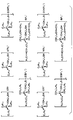
上記一般式(1)で表されるイオン液体13bとして、図3に記載の化合物を例示できるが、これらに限定されるものではない。なお、図3の化合物は、一般式(1)中のR1に、「-SS-基」もしくは「-SH基」を有している。
Although the compound of FIG. 3 can be illustrated as an ionic liquid 13b represented by the said General formula (1), it is not limited to these. 3 has “—SS— group” or “—SH group” at R 1 in the general formula (1).
本実施形態では、イオン液体13bとして、以下の一般式(2)で表される有機化合物を用いている。一般式(2)で表される有機化合物は、上記一般式(1)において、MがP原子、R1が結合性官能基として-S-基を有する-(CH2)12S-基、R2~R4がC6H13-基、X-がCF3SO3
-(TfO-)である。
In the present embodiment, an organic compound represented by the following general formula (2) is used as the ionic liquid 13b. The organic compound represented by the general formula (2) is an organic compound represented by the general formula (1), in which M is a P atom and R 1 is a — (CH 2 ) 12 S— group having a —S— group as a binding functional group, R 2 to R 4 are C 6 H 13 — groups, and X − is CF 3 SO 3 − (TfO − ).

メディエータ13cは、CO2還元反応で電子伝達を仲介する化合物である。本実施形態では、メディエータ13cとして、窒素含有芳香族化合物を用いている。芳香族化合物は、4n+2個(nは整数)のπ電子を含有する非局在π電子系を有する平面環である。芳香環は、5、6、7、8、9個、又は10個以上の原子によって形成され得る。芳香族化合物は、単環式および縮合環多環式を含んでいる。
The mediator 13c is a compound that mediates electron transfer through a CO 2 reduction reaction. In the present embodiment, a nitrogen-containing aromatic compound is used as the mediator 13c. The aromatic compound is a planar ring having a delocalized π electron system containing 4n + 2 (n is an integer) π electrons. Aromatic rings can be formed by 5, 6, 7, 8, 9, or 10 or more atoms. Aromatic compounds include monocyclic and fused ring polycyclic.
窒素含有芳香族化合物は、芳香環の構成原子の1以上がN原子となっている複素芳香族化合物である。窒素含有芳香族化合物は、芳香環の構成原子と結合する1以上の水素が、直鎖または分岐鎖低級アルキル基、ヒドロキシ基、アミノ基、ピリジル基で置換されていてもよい。本実施形態では、メディエータ13cを構成する窒素含有芳香族化合物として、例えばイミダゾール、メチルイミダゾール、ジメチルイミダゾール、トリアゾール、ピリジン、ジメチルアミノピリジンを用いている。
The nitrogen-containing aromatic compound is a heteroaromatic compound in which one or more constituent atoms of the aromatic ring are N atoms. In the nitrogen-containing aromatic compound, one or more hydrogen atoms bonded to the constituent atoms of the aromatic ring may be substituted with a linear or branched lower alkyl group, a hydroxy group, an amino group, or a pyridyl group. In the present embodiment, for example, imidazole, methylimidazole, dimethylimidazole, triazole, pyridine, dimethylaminopyridine are used as the nitrogen-containing aromatic compound constituting the mediator 13c.
本実施形態の還元電極13は、基材13a表面にイオン液体13bを導入してイオン液体修飾基材とし、このイオン液体修飾基材にメディエータ13cを導入することで得られる。基材13aは、イオン液体13bによる修飾前に、必要に応じて清浄化などの表面処理をしておくことが望ましい。基材13aの表面処理は、濃硝酸、ピランハ溶液、あるいはフッ化水素酸を用いて行うことができる。
The reduction electrode 13 of the present embodiment can be obtained by introducing the ionic liquid 13b to the surface of the base material 13a to make the ionic liquid modified base material, and introducing the mediator 13c into the ionic liquid modified base material. The base material 13a is preferably subjected to surface treatment such as cleaning as necessary before modification with the ionic liquid 13b. The surface treatment of the substrate 13a can be performed using concentrated nitric acid, a piranha solution, or hydrofluoric acid.
結合性官能基を含むイオン液体13bを基材13a表面へ化学結合させ、イオン液体修飾基材を得る方法としては、例えば、有機溶媒にイオン液体13bを溶解させた溶液に基材13aを浸漬する方法、あるいは溶液を基材13a表面にスプレーコートやスピンコートなどにより塗布する方法を用いることができる。また、イオン液体13bそのものに基材13aを浸漬、あるいはイオン液体13bを上記方法により基材13a表面に塗布してもよい。
As a method of chemically bonding the ionic liquid 13b containing a binding functional group to the surface of the base material 13a to obtain an ionic liquid modified base material, for example, the base material 13a is immersed in a solution in which the ionic liquid 13b is dissolved in an organic solvent. A method or a method of applying the solution to the surface of the substrate 13a by spray coating or spin coating can be used. Alternatively, the substrate 13a may be immersed in the ionic liquid 13b itself, or the ionic liquid 13b may be applied to the surface of the substrate 13a by the above method.
基材13aをイオン液体13bの溶液等に浸漬する時間は、イオン液体13bが基材13a表面に固定されれば特に制限されることはないが、好ましくは5分~60時間、より好ましくは1~24時間である。また、必要に応じて浸漬あるいは塗布する際に基材13aや溶液を加熱してもよい。溶液にする場合、イオン液体13bの濃度としては、0.01~100mmol/L、好ましくは0.1~50mmol/L程度である。有機溶媒としては、アルコール類、エーテル類、ニトリル類、エステル類、ケトン類、炭化水素、クロロホルムなどを用いることができる。
The time for immersing the base material 13a in the solution of the ionic liquid 13b is not particularly limited as long as the ionic liquid 13b is fixed on the surface of the base material 13a, but preferably 5 minutes to 60 hours, more preferably 1 ~ 24 hours. Moreover, you may heat the base material 13a and a solution when immersing or apply | coating as needed. In the case of a solution, the concentration of the ionic liquid 13b is about 0.01 to 100 mmol / L, preferably about 0.1 to 50 mmol / L. As the organic solvent, alcohols, ethers, nitriles, esters, ketones, hydrocarbons, chloroform and the like can be used.
イオン液体修飾基材へのメディエータ13cの導入方法としては、例えば、有機溶媒にメディエータ13cを溶解させた溶液にイオン液体修飾基材を浸漬する方法、あるいは溶液をイオン液体修飾基材にスプレーコートやスピンコートなどにより塗布する方法などが挙げられる。
As a method for introducing the mediator 13c into the ionic liquid modified substrate, for example, a method in which the ionic liquid modified substrate is immersed in a solution in which the mediator 13c is dissolved in an organic solvent, or a solution is spray coated on the ionic liquid modified substrate. The method of apply | coating by spin coating etc. is mentioned.
イオン液体修飾基材をメディエータ13cの溶液に浸漬する時間は、メディエータ13bがイオン液体修飾基材に導入されれば特に制限されることはないが、好ましくは5分~60時間、より好ましくは1~24時間である。また、必要に応じて浸漬あるいは塗布する際にイオン液体修飾基材や溶液を加熱しても良い。溶液にする場合、目的化合物の濃度としては、0.01~100mmol/L、好ましくは0.1~50mmol/L程度である。有機溶媒としては、アルコール類、エーテル類、ニトリル類、エステル類、ケトン類、炭化水素、クロロホルム、水などを用いることができる。
The time for immersing the ionic liquid modified base material in the solution of the mediator 13c is not particularly limited as long as the mediator 13b is introduced into the ionic liquid modified base material, but is preferably 5 minutes to 60 hours, more preferably 1 ~ 24 hours. Moreover, you may heat an ionic liquid modification base material and a solution when immersing or apply | coating as needed. In the case of a solution, the concentration of the target compound is about 0.01 to 100 mmol / L, preferably about 0.1 to 50 mmol / L. As the organic solvent, alcohols, ethers, nitriles, esters, ketones, hydrocarbons, chloroform, water and the like can be used.
また、イオン液体13bおよびメディエータ13cの他の導入方法として、基材13a表面へのイオン液体修飾の際に、イオン液体13bとメディエータ13cを共存させた溶液を調製し、一度にイオン液体13bとメディエータ13cを基材13a表面上に修飾・固定することも可能である。基材13aを溶液に浸漬する時間は、メディエータ13cおよびイオン液体13bが基材13a表面に導入されれば特に制限されることはないが、好ましくは5分~60時間、より好ましくは1~24時間である。また必要に応じて浸漬する際に基材や溶液を加熱しても良い。溶液にする場合、メディエータ13cの濃度としては、0.01~100mmol/L、好ましくは0.1~50mmol/L程度である。有機溶媒としては、アルコール類、エーテル類、ニトリル類、エステル類、ケトン類、炭化水素、クロロホルムなどを用いることができる。
As another method of introducing the ionic liquid 13b and the mediator 13c, a solution in which the ionic liquid 13b and the mediator 13c coexist is prepared at the time of modifying the ionic liquid on the surface of the base material 13a. It is also possible to modify and fix 13c on the surface of the base material 13a. The time for immersing the substrate 13a in the solution is not particularly limited as long as the mediator 13c and the ionic liquid 13b are introduced onto the surface of the substrate 13a, but preferably 5 minutes to 60 hours, more preferably 1 to 24. It's time. Moreover, you may heat a base material and a solution, when immersing as needed. In the case of forming a solution, the concentration of the mediator 13c is about 0.01 to 100 mmol / L, preferably about 0.1 to 50 mmol / L. As the organic solvent, alcohols, ethers, nitriles, esters, ketones, hydrocarbons, chloroform and the like can be used.
更に、メディエータ13cの別の導入方法として、イオン液体修飾基材を電極とし、電気化学測定装置を用いて、メディエータ13cを含んだ電解質溶液中で電気化学測定、好ましくはサイクリックボルタンメトリーなどのポテンシオメトリー測定を行うことにより、イオン液体修飾電極中に電解質溶液中のメディエータ13cを導入することが可能である。
Furthermore, as another method for introducing the mediator 13c, an electrochemical measurement is performed in an electrolyte solution containing the mediator 13c using an ionic liquid-modified base as an electrode and an electrochemical measurement device, preferably a potentio such as cyclic voltammetry. By performing the measurement, it is possible to introduce the mediator 13c in the electrolyte solution into the ionic liquid modified electrode.
測定の際の各種条件(濃度、温度、溶媒、測定時間、用いる電解質など)はメディエータ13cがイオン液体修飾電極中に導入されれば特に制限されることはないが、導入するメディエータ13cの濃度は好ましくは0.05~10mmol/L、より好ましくは0.1~5mmol/Lである。また測定する際の温度は好ましくは-10~100℃、より好ましくは0~30℃である。有機溶媒としては、アルコール類、エーテル類、ニトリル類、エステル類、ケトン類、炭化水素、クロロホルム、水などを用いることができる。測定時間は好ましくは1分~2時間程度、より好ましくは5~30分程度である。
Various conditions for measurement (concentration, temperature, solvent, measurement time, electrolyte to be used, etc.) are not particularly limited as long as the mediator 13c is introduced into the ionic liquid modified electrode, but the concentration of the mediator 13c to be introduced is Preferably it is 0.05 to 10 mmol / L, more preferably 0.1 to 5 mmol / L. The measurement temperature is preferably −10 to 100 ° C., more preferably 0 to 30 ° C. As the organic solvent, alcohols, ethers, nitriles, esters, ketones, hydrocarbons, chloroform, water and the like can be used. The measurement time is preferably about 1 minute to 2 hours, more preferably about 5 to 30 minutes.
電解質に関しては、通常の電気化学測定に使用する電解質であれば特に制限はなく、溶媒が水系であれば、過塩素酸リチウムや過塩素酸ナトリウム、有機溶媒であればテトラアルキルアンモニウムのテトラボレート塩やヘキサフルオロリン酸塩、あるいは過塩素酸塩が好適に用いられる。
The electrolyte is not particularly limited as long as it is an electrolyte used for normal electrochemical measurements. If the solvent is aqueous, lithium perchlorate or sodium perchlorate, and an organic solvent, tetraalkylammonium tetraborate salt. , Hexafluorophosphate, or perchlorate is preferably used.
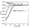
図4は、本実施形態のCO2還元装置1でCV測定した結果を示している。メディエータ13cとしてイミダゾールを用いた。図4では、比較例1として、電解液11にCO2を供給しない場合のCV測定結果を示し、比較例2として、基材13a表面にイオン液体13bの単分子膜を形成することなく電解液11にイミダゾールを分散させた場合のCV測定結果を示している。
FIG. 4 shows the result of CV measurement performed by the CO 2 reduction device 1 of the present embodiment. Imidazole was used as the mediator 13c. In FIG. 4, the CV measurement result when not supplying CO 2 to the electrolytic solution 11 is shown as the comparative example 1, and the electrolytic solution is formed as the comparative example 2 without forming a monomolecular film of the ionic liquid 13b on the surface of the base material 13a. 11 shows the results of CV measurement when imidazole is dispersed in No. 11.
図4に示すように、電解液11にCO2を供給しない比較例1では、電流がゼロ付近のまま推移している。イオン液体13bを用いていない比較例2では、-0.6V付近で電流がゼロからマイナスに推移している。イオン液体13bを用いた本実施形態では、-0.4V付近で電流がゼロからマイナスに推移している。また、本実施形態では、比較例2よりも電流密度が増大している。つまり、本実施形態では、イオン液体13bを用いることで、CO2還元反応における反応過電圧が低下しているとともに反応電流が増大している。
As shown in FIG. 4, in Comparative Example 1 in which CO 2 is not supplied to the electrolyte solution 11, the current is kept near zero. In Comparative Example 2 in which the ionic liquid 13b is not used, the current changes from zero to minus around −0.6V. In the present embodiment using the ionic liquid 13b, the current changes from zero to minus around −0.4V. In the present embodiment, the current density is increased as compared with Comparative Example 2. That is, in this embodiment, by using the ionic liquid 13b, the reaction overvoltage in the CO 2 reduction reaction is reduced and the reaction current is increased.
本実施形態では、イオン液体13bとメディエータ13cが相互作用の高い組み合わせとなっており、還元電極13最表面での被還元体の拡散が少なくなっていると考えられる。この結果、本実施形態では、CO2還元反応での電荷移動が効率的となり、反応過電圧が低下するとともに反応電流が増大したものと推測される。
In this embodiment, it is considered that the ionic liquid 13b and the mediator 13c are a combination having a high interaction, and the diffusion of the reductant on the outermost surface of the reduction electrode 13 is reduced. As a result, in the present embodiment, it is presumed that the charge transfer in the CO 2 reduction reaction is efficient, the reaction overvoltage is reduced, and the reaction current is increased.
CO2還元反応は、CO2→ギ酸(HCOOH)→メタノール(CH3OH)の順に変化する多段階反応である。電解液中にイミダゾールを分散させた比較例2では、被還元体がギ酸の段階で電極表面から拡散し、CO2還元反応をメタノール生成まで進行させることが難しい。これに対し、本実施形態では、伝導性が高く、メディエータ13cおよび被還元体(反応物)の内包性が高いイオン液体13bの単分子膜を基材13a表面に形成することで、被還元体がギ酸の段階で電極表面から拡散することを抑制でき、上記多段階反応が円滑に進行すると考えられる。
The CO 2 reduction reaction is a multistage reaction that changes in the order of CO 2 → formic acid (HCOOH) → methanol (CH 3 OH). In Comparative Example 2 in which imidazole is dispersed in the electrolytic solution, it is difficult for the substance to be reduced to diffuse from the electrode surface at the formic acid stage and to proceed the CO 2 reduction reaction to the formation of methanol. In contrast, in the present embodiment, a monomolecular film of the ionic liquid 13b having high conductivity and high inclusion of the mediator 13c and the reductant (reactant) is formed on the surface of the base material 13a, thereby reducing the reductant. Can be prevented from diffusing from the electrode surface at the formic acid stage, and the above multi-stage reaction is considered to proceed smoothly.
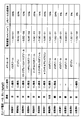
図5は、本実施形態のCO2還元装置1において、基材13a、イオン液体13b、メディエータ13cの組み合わせを変化させてCO2の還元を行った実施例の電流密度とメタノール生成効率を示している。図5では、イオン液体13bあるいはメディエータ13bを用いることなくCO2の還元を行った比較例も示している。なお、カソード電位を-0.8V/Ag/AgClとした。
FIG. 5 shows the current density and methanol production efficiency of an example in which CO 2 was reduced by changing the combination of the base material 13a, the ionic liquid 13b, and the mediator 13c in the CO 2 reduction apparatus 1 of the present embodiment. Yes. FIG. 5 also shows a comparative example in which CO 2 is reduced without using the ionic liquid 13b or the mediator 13b. The cathode potential was −0.8 V / Ag / AgCl.
基材13aは、実施例1~7、比較例1、3、4では金を用い、実施例8では白金を用い、実施例9、比較例2では銅を用いた。イオン液体13bは、実施例1~9、比較例4ではP原子を含むリン酸系のイオン液体13bを用いた。比較例1~3では、イオン液体13bを用いなかった。
As the base material 13a, gold was used in Examples 1 to 7 and Comparative Examples 1, 3, and 4, platinum was used in Example 8, and copper was used in Examples 9 and 2. As the ionic liquid 13b, in Examples 1 to 9 and Comparative Example 4, a phosphoric acid ionic liquid 13b containing P atoms was used. In Comparative Examples 1 to 3, the ionic liquid 13b was not used.
メディエータ13cは、実施例1、8、9、比較例1、2ではイミダゾールを用い、実施例2、比較例3ではピリジンを用い、実施例3では3,5-ジアミノ-1,2,4-トリアゾールを用い、実施例4では1-メチルイミダゾールを用い、実施例5では2-メチルイミダゾール、実施例6では1,2-ジメチルイミダゾールを用い、実施例7では4-ジメチルイミダゾールを用いた。比較例4ではメディエータ13cを用いなかった。
The mediator 13c uses imidazole in Examples 1, 8, and 9, Comparative Examples 1 and 2, pyridine in Examples 2 and 3, and 3,5-diamino-1,2,4- in Example 3. Triazole was used, 1-methylimidazole was used in Example 4, 2-methylimidazole was used in Example 5, 1,2-dimethylimidazole was used in Example 6, and 4-dimethylimidazole was used in Example 7. In Comparative Example 4, the mediator 13c was not used.
図5に示すように、本実施形態の還元電極13を用いた実施例1~9では、メタノール生成効率が13%~28%となった。イオン液体13bを用いず、メディエータ13cを用いた比較例1~3では、メタノール生成効率が1~6%となった。さらに、イオン液体13bを用い、メディエータ13cを用いなかった比較例4では、メタノール生成効率が0%となった。つまり、本実施形態では、比較例よりも高いメタノール生成効率が得られている。
As shown in FIG. 5, in Examples 1 to 9 using the reduction electrode 13 of this embodiment, the methanol production efficiency was 13% to 28%. In Comparative Examples 1 to 3 using the mediator 13c without using the ionic liquid 13b, the methanol production efficiency was 1 to 6%. Furthermore, in Comparative Example 4 in which the ionic liquid 13b was used and the mediator 13c was not used, the methanol production efficiency was 0%. That is, in this embodiment, methanol production efficiency higher than that of the comparative example is obtained.
実施例1~9の中では、基板12aとして金を用いた場合が、他の金属に比較してメタノール生成効率が高くなっている。また、実施例1~9の中では、基板12aとして金を用い、メディエータ13cとしてイミダゾールを用いた場合が最もメタノール生成効率が高くなっている。
In Examples 1 to 9, when gold is used as the substrate 12a, methanol production efficiency is higher than other metals. In Examples 1 to 9, the methanol production efficiency is highest when gold is used as the substrate 12a and imidazole is used as the mediator 13c.
なお、基材13aとして用いられた金属の種類は、例えばXPSによる元素分析により判断可能である。基材13a表面におけるイオン液体13bの単分子膜の有無は、例えば電気化学的還元方法(すなわち電気的な単分子膜の脱離)によって判断できる。イオン液体13bの単分子膜の種類は、例えばXRSやEDXを用いた元素分析により判断できる。メディエータ13cの種類は、例えばXPS、EDS、ガスクロマトグラフィなどによって分析可能である。
In addition, the kind of metal used as the base material 13a can be determined by elemental analysis by XPS, for example. The presence / absence of the monomolecular film of the ionic liquid 13b on the surface of the base material 13a can be determined by, for example, an electrochemical reduction method (that is, electrical desorption of the monomolecular film). The type of the monomolecular film of the ionic liquid 13b can be determined by elemental analysis using, for example, XRS or EDX. The type of mediator 13c can be analyzed by, for example, XPS, EDS, gas chromatography, or the like.
以上説明した本実施形態によれば、基材13a表面にイオン液体13bの単分子膜を形成し、基材13aとイオン液体13bの間にメディエータ13cを内包させることで、CO2還元反応を行った際のメタノール生成効率を向上させることができる。また、本実施形態によれば、CO2還元反応において、反応過電圧が低下するとともに、反応電流が増大している。このため、メタノールの絶対的な生成量を増大させることができる。
According to the present embodiment described above, a monomolecular film of the ionic liquid 13b is formed on the surface of the base material 13a, and the mediator 13c is included between the base material 13a and the ionic liquid 13b to perform the CO 2 reduction reaction. The methanol production efficiency can be improved. Further, according to the present embodiment, in the CO 2 reduction reaction, the reaction overvoltage decreases and the reaction current increases. For this reason, the absolute production amount of methanol can be increased.
(他の実施形態)
メディエータ13cは、上記実施形態で例示した窒素含有芳香族化合物に限定されないが、イオン液体13bとして上記一般式(2)で表される有機化合物を用いる場合には、窒素含有芳香族化合物の反応電位が-1.0V/Ag/AgClより正側に小さいことが望ましい。すなわち、イオン液体13bとして上記一般式(2)で表される有機化合物を用いる場合には、-1.0V/Ag/AgCl程度の電位でイオン液体13bの単分子膜が基材13aから還元脱離するおそれがある。このため、反応電位が-1.0V/Ag/AgClより正側に小さい窒素含有芳香族化合物をメディエータ13cとして用いることで、CO2還元反応中にイオン液体13bの単分子膜が基材13aから還元脱離することを回避できる。 (Other embodiments)
Themediator 13c is not limited to the nitrogen-containing aromatic compound exemplified in the above embodiment, but when the organic compound represented by the general formula (2) is used as the ionic liquid 13b, the reaction potential of the nitrogen-containing aromatic compound is used. Is desirably smaller than −1.0 V / Ag / AgCl on the positive side. That is, when the organic compound represented by the general formula (2) is used as the ionic liquid 13b, the monomolecular film of the ionic liquid 13b is reduced and desorbed from the substrate 13a at a potential of about −1.0 V / Ag / AgCl. There is a risk of separation. For this reason, by using a nitrogen-containing aromatic compound having a reaction potential smaller than −1.0 V / Ag / AgCl on the positive side as the mediator 13c, the monomolecular film of the ionic liquid 13b is removed from the substrate 13a during the CO 2 reduction reaction. Reductive desorption can be avoided.
メディエータ13cは、上記実施形態で例示した窒素含有芳香族化合物に限定されないが、イオン液体13bとして上記一般式(2)で表される有機化合物を用いる場合には、窒素含有芳香族化合物の反応電位が-1.0V/Ag/AgClより正側に小さいことが望ましい。すなわち、イオン液体13bとして上記一般式(2)で表される有機化合物を用いる場合には、-1.0V/Ag/AgCl程度の電位でイオン液体13bの単分子膜が基材13aから還元脱離するおそれがある。このため、反応電位が-1.0V/Ag/AgClより正側に小さい窒素含有芳香族化合物をメディエータ13cとして用いることで、CO2還元反応中にイオン液体13bの単分子膜が基材13aから還元脱離することを回避できる。 (Other embodiments)
The
本開示は、実施形態に準拠して記述されたが、本開示は当該実施形態や構造に限定されるものではないと理解される。本開示は、様々な変形例や均等範囲内の変形をも包含する。加えて、様々な組み合わせや形態、さらには、それらに一要素のみ、それ以上、あるいはそれ以下、を含む他の組み合わせや形態をも、本開示の範疇や思想範囲に入るものである。
Although the present disclosure has been described based on the embodiment, it is understood that the present disclosure is not limited to the embodiment or the structure. The present disclosure includes various modifications and modifications within the equivalent range. In addition, various combinations and forms, as well as other combinations and forms including only one element, more or less, are within the scope and spirit of the present disclosure.
Claims (7)
- 金属あるいは金属酸化物によって構成されている基材(13a)と、
下記の一般式(1)で表されるとともに、前記基材の表面に単分子膜を形成するイオン液体(13b)と、
前記基材と前記イオン液体との間に内包される窒素含有芳香族化合物(13c)と、
を備える二酸化炭素還元電極であって
一般式(1)において、
MはP原子またはN原子であり、
R1~R4は、それぞれ独立に、炭素数1~30のアルキル基、炭素数2~30のアルケニル基、炭素数2~30のアルキニル基、炭素数1~30のアルコキシアルキル基、炭素数1~30のアミノアルキル基、炭素数1~30のパーフルオロアルキル基、炭素数6~30のアリール基、炭素数7~30のアラルキル基、またはカルボニル基を有するアルキル基、アルケニル基、アリール基もしくはアラルキル基を表し、
nを1~3の整数としたとき、RnとRn+1は結合して環状構造を有していてもよく、
R1~R4の少なくとも1つは、-SH基、-SS-基、-S-基、-COOH基、-NH2基、シラノ-ル基、リン酸基、アルケニル基、アルキニル基、アジ基からなる群から選ばれる一種以上の結合性官能基を有し、
X-は対陰イオンを表す二酸化炭素還元電極。

An ionic liquid (13b) represented by the following general formula (1) and forming a monomolecular film on the surface of the substrate;
A nitrogen-containing aromatic compound (13c) encapsulated between the substrate and the ionic liquid;
A carbon dioxide reduction electrode comprising the following general formula (1):
M is a P atom or an N atom,
R 1 to R 4 are each independently an alkyl group having 1 to 30 carbon atoms, an alkenyl group having 2 to 30 carbon atoms, an alkynyl group having 2 to 30 carbon atoms, an alkoxyalkyl group having 1 to 30 carbon atoms, An alkyl group having 1 to 30 aminoalkyl groups, a perfluoroalkyl group having 1 to 30 carbon atoms, an aryl group having 6 to 30 carbon atoms, an aralkyl group having 7 to 30 carbon atoms, or a carbonyl group, an alkenyl group, and an aryl group Or represents an aralkyl group,
When n is an integer of 1 to 3, R n and R n + 1 may be bonded to each other to have a cyclic structure,
At least one of R 1 to R 4 is —SH, —SS—, —S—, —COOH, —NH 2 , silanol, phosphoric acid, alkenyl, alkynyl, Having one or more binding functional groups selected from the group consisting of groups,
X − is a carbon dioxide reducing electrode representing a counter anion.
- 前記イオン液体は、下記の一般式(2)で表される請求項1に記載の二酸化炭素還元電極。

- 前記イオン液体の前記結合性官能基が、前記基材の表面の金属あるいは金属酸化物と化学結合を形成している請求項1または2に記載の二酸化炭素還元電極。 The carbon dioxide reduction electrode according to claim 1 or 2, wherein the binding functional group of the ionic liquid forms a chemical bond with a metal or metal oxide on the surface of the substrate.
- 前記基材は、金、白金、銀、銅、スズ、チタンからなる群から選ばれる一種以上の金属あるいは金属酸化物によって構成されている請求項1ないし3のいずれか1つに記載の二酸化炭素還元電極。 The carbon dioxide according to any one of claims 1 to 3, wherein the substrate is composed of one or more metals or metal oxides selected from the group consisting of gold, platinum, silver, copper, tin, and titanium. Reduction electrode.
- 前記窒素含有芳香族化合物は、芳香環の構成原子の1以上がN原子となっている複素芳香族化合物であり、
芳香環の構成原子と結合する1以上の水素が、直鎖低級アルキル基、分岐鎖低級アルキル基、ヒドロキシ基、アミノ基、ピリジル基からなる群から選ばれる一種以上で置換されている請求項1ないし4のいずれか1つに記載の二酸化炭素還元電極。 The nitrogen-containing aromatic compound is a heteroaromatic compound in which one or more constituent atoms of the aromatic ring are N atoms,
2. One or more hydrogen atoms bonded to a constituent atom of an aromatic ring are substituted with one or more selected from the group consisting of a linear lower alkyl group, a branched lower alkyl group, a hydroxy group, an amino group, and a pyridyl group. 5. The carbon dioxide reducing electrode according to any one of items 4 to 4. - 前記窒素含有芳香族化合物は、イミダゾール、メチルイミダゾール、ジメチルイミダゾール、トリアゾール、ピリジン、ジメチルアミノピリジンからなる群から選ばれる一種以上である請求項5に記載の二酸化炭素還元電極。 The carbon dioxide reducing electrode according to claim 5, wherein the nitrogen-containing aromatic compound is one or more selected from the group consisting of imidazole, methylimidazole, dimethylimidazole, triazole, pyridine, and dimethylaminopyridine.
- 請求項1ないし6のいずれか1つに記載の二酸化炭素還元電極(13)と、
酸化電極(12)と、
前記二酸化炭素還元電極および前記酸化電極が浸漬された電解液(11)と、
前記電解液に二酸化炭素を供給する二酸化炭素供給部(16)と、
を備える二酸化炭素還元装置。 Carbon dioxide reduction electrode (13) according to any one of claims 1 to 6,
An oxidation electrode (12);
An electrolyte solution (11) in which the carbon dioxide reduction electrode and the oxidation electrode are immersed;
A carbon dioxide supply section (16) for supplying carbon dioxide to the electrolytic solution;
A carbon dioxide reduction device comprising:
Applications Claiming Priority (2)
| Application Number | Priority Date | Filing Date | Title |
|---|---|---|---|
| JP2016-070181 | 2016-03-31 | ||
| JP2016070181A JP6590459B2 (en) | 2016-03-31 | 2016-03-31 | Carbon dioxide reduction electrode and carbon dioxide reduction apparatus using the same |
Publications (1)
| Publication Number | Publication Date |
|---|---|
| WO2017170199A1 true WO2017170199A1 (en) | 2017-10-05 |
Family
ID=59965598
Family Applications (1)
| Application Number | Title | Priority Date | Filing Date |
|---|---|---|---|
| PCT/JP2017/011946 WO2017170199A1 (en) | 2016-03-31 | 2017-03-24 | Carbon dioxide reduction electrode and carbon dioxide reduction device using same |
Country Status (2)
| Country | Link |
|---|---|
| JP (1) | JP6590459B2 (en) |
| WO (1) | WO2017170199A1 (en) |
Cited By (1)
| Publication number | Priority date | Publication date | Assignee | Title |
|---|---|---|---|---|
| JP2021014629A (en) * | 2019-07-16 | 2021-02-12 | 株式会社豊田中央研究所 | Reductive reaction electrode, and reaction device using the same |
Families Citing this family (2)
| Publication number | Priority date | Publication date | Assignee | Title |
|---|---|---|---|---|
| JP7062939B2 (en) * | 2017-12-18 | 2022-05-09 | 株式会社デンソー | Carbon dioxide reduction electrode and carbon dioxide reduction device using this |
| CN110699704B (en) * | 2019-10-21 | 2021-05-11 | 昆明理工大学 | Preparation method, product and application of self-supporting silver sulfide catalytic carbon dioxide reduction electrode material |
Citations (5)
| Publication number | Priority date | Publication date | Assignee | Title |
|---|---|---|---|---|
| JP2012167045A (en) * | 2011-02-14 | 2012-09-06 | Nagoya Institute Of Technology | Ionic liquid and ionic liquid-decorated base material |
| JP2012184132A (en) * | 2011-03-04 | 2012-09-27 | Nagoya Institute Of Technology | Ammonia production method |
| JP2015513616A (en) * | 2012-03-06 | 2015-05-14 | リキッド・ライト・インコーポレーテッドLiquid Light Incorporated | Reduction of carbon dioxide to product |
| WO2015133127A1 (en) * | 2014-03-04 | 2015-09-11 | 株式会社デンソー | Carbon dioxide reduction electrode and carbon dioxide reduction device in which same is used |
| WO2015136776A1 (en) * | 2014-03-14 | 2015-09-17 | 株式会社 東芝 | Oxidation electrode and photoelectrochemical apparatus |
-
2016
- 2016-03-31 JP JP2016070181A patent/JP6590459B2/en active Active
-
2017
- 2017-03-24 WO PCT/JP2017/011946 patent/WO2017170199A1/en active Application Filing
Patent Citations (5)
| Publication number | Priority date | Publication date | Assignee | Title |
|---|---|---|---|---|
| JP2012167045A (en) * | 2011-02-14 | 2012-09-06 | Nagoya Institute Of Technology | Ionic liquid and ionic liquid-decorated base material |
| JP2012184132A (en) * | 2011-03-04 | 2012-09-27 | Nagoya Institute Of Technology | Ammonia production method |
| JP2015513616A (en) * | 2012-03-06 | 2015-05-14 | リキッド・ライト・インコーポレーテッドLiquid Light Incorporated | Reduction of carbon dioxide to product |
| WO2015133127A1 (en) * | 2014-03-04 | 2015-09-11 | 株式会社デンソー | Carbon dioxide reduction electrode and carbon dioxide reduction device in which same is used |
| WO2015136776A1 (en) * | 2014-03-14 | 2015-09-17 | 株式会社 東芝 | Oxidation electrode and photoelectrochemical apparatus |
Cited By (2)
| Publication number | Priority date | Publication date | Assignee | Title |
|---|---|---|---|---|
| JP2021014629A (en) * | 2019-07-16 | 2021-02-12 | 株式会社豊田中央研究所 | Reductive reaction electrode, and reaction device using the same |
| JP7342474B2 (en) | 2019-07-16 | 2023-09-12 | 株式会社豊田中央研究所 | Carbon dioxide reduction reaction electrode and carbon dioxide reduction device using the same |
Also Published As
| Publication number | Publication date |
|---|---|
| JP2017179514A (en) | 2017-10-05 |
| JP6590459B2 (en) | 2019-10-16 |
Similar Documents
| Publication | Publication Date | Title |
|---|---|---|
| Suryanto et al. | MoS2 polymorphic engineering enhances selectivity in the electrochemical reduction of nitrogen to ammonia | |
| Zhao et al. | Speciation of Cu surfaces during the electrochemical CO reduction reaction | |
| Zeng et al. | Electrochemically sensing of trichloroacetic acid with iron (II) phthalocyanine and Zn-based metal organic framework nanocomposites | |
| Du et al. | Effect of water presence on choline chloride-2urea ionic liquid and coating platings from the hydrated ionic liquid | |
| Arul et al. | Covalent organic framework film as an effective electrocatalyst for the simultaneous determination of dihydroxybenzene isomers in water samples | |
| Vieira et al. | Mechanistic studies of zinc electrodeposition from deep eutectic electrolytes | |
| Liu et al. | A combined theoretical and experimental study for silver electroplating | |
| WO2017170199A1 (en) | Carbon dioxide reduction electrode and carbon dioxide reduction device using same | |
| Schaltin et al. | Electrodeposition from cationic cuprous organic complexes: ionic liquids for high current density electroplating | |
| JP6636885B2 (en) | Reduction catalyst and reduction reactor | |
| Marwan et al. | Functionalization of glassy carbon electrodes with metal-based species | |
| Huang et al. | Electrochemical study of Pt and Fe and electrodeposition of PtFe alloys from air-and water-stable room temperature ionic liquids | |
| Zhang et al. | Interfacial engineering of SeO ligands on tellurium featuring synergistic functionalities of bond activation and chemical states buffering toward electrocatalytic conversion of nitrogen to ammonia | |
| Huang et al. | Voltammetric behavior of Pd (II) and Ni (II) ions and electrodeposition of PdNi bimetal in N-butyl-N-methylpyrrolidinium dicyanamide ionic liquid | |
| Vanderaspoilden et al. | Contrasted electrochemical behaviour of Cu (I) and Cu (II) ions in 1-butyl-3-methylimidazolium dicyanamide | |
| Xie et al. | Voltammetric study and electrodeposition of Cu from CuO in deep eutectic solvents | |
| Mironov et al. | On Gold (I) Complexes and Anodic Gold Dissolution in Sulfite–Thiourea Solutions | |
| Park et al. | Electrochemical Ce (III)/Ce (IV) redox behavior and Ce oxide nanostructure recovery over thio-terpyridine-functionalized Au/carbon paper electrodes | |
| Liu et al. | An electrochemical chiral sensor based on the synergy of chiral ionic liquid and 3D-NGMWCNT for tryptophan enantioselective recognition | |
| Guo et al. | Investigation of the pronounced medium effects observed in the voltammetry of the highly charged lacunary anions [α-SiW11O39] 8-and [α-PW11O39] 7 | |
| Chouki et al. | Highly active iron phosphide catalysts for selective electrochemical nitrate reduction to ammonia | |
| Gupta et al. | Photochemical assisted formation of silver nano dendrites and their application in amperometric sensing of nitrite | |
| Lee et al. | Electrooxidative grafting of amine-terminated dendrimers encapsulating nanoparticles for spatially controlled surface functionalization of indium tin oxide | |
| Pašti et al. | Adsorption of acetonitrile on platinum and its effects on oxygen reduction reaction in acidic aqueous solutions—combined theoretical and experimental study | |
| JP2017101285A (en) | Electrode for reduction reaction and reaction device prepared therewith |
Legal Events
| Date | Code | Title | Description |
|---|---|---|---|
| NENP | Non-entry into the national phase |
Ref country code: DE |
|
| 121 | Ep: the epo has been informed by wipo that ep was designated in this application |
Ref document number: 17774736 Country of ref document: EP Kind code of ref document: A1 |
|
| 122 | Ep: pct application non-entry in european phase |
Ref document number: 17774736 Country of ref document: EP Kind code of ref document: A1 |