WO2017169996A1 - 生体情報計測装置 - Google Patents
生体情報計測装置 Download PDFInfo
- Publication number
- WO2017169996A1 WO2017169996A1 PCT/JP2017/011294 JP2017011294W WO2017169996A1 WO 2017169996 A1 WO2017169996 A1 WO 2017169996A1 JP 2017011294 W JP2017011294 W JP 2017011294W WO 2017169996 A1 WO2017169996 A1 WO 2017169996A1
- Authority
- WO
- WIPO (PCT)
- Prior art keywords
- biological information
- pressure sensor
- sensor
- information measuring
- pulse wave
- Prior art date
- Legal status (The legal status is an assumption and is not a legal conclusion. Google has not performed a legal analysis and makes no representation as to the accuracy of the status listed.)
- Ceased
Links
Images





Classifications
-
- A—HUMAN NECESSITIES
- A61—MEDICAL OR VETERINARY SCIENCE; HYGIENE
- A61B—DIAGNOSIS; SURGERY; IDENTIFICATION
- A61B5/00—Measuring for diagnostic purposes; Identification of persons
-
- A—HUMAN NECESSITIES
- A61—MEDICAL OR VETERINARY SCIENCE; HYGIENE
- A61B—DIAGNOSIS; SURGERY; IDENTIFICATION
- A61B5/00—Measuring for diagnostic purposes; Identification of persons
- A61B5/02—Detecting, measuring or recording for evaluating the cardiovascular system, e.g. pulse, heart rate, blood pressure or blood flow
-
- A—HUMAN NECESSITIES
- A61—MEDICAL OR VETERINARY SCIENCE; HYGIENE
- A61B—DIAGNOSIS; SURGERY; IDENTIFICATION
- A61B5/00—Measuring for diagnostic purposes; Identification of persons
- A61B5/08—Measuring devices for evaluating the respiratory organs
-
- A—HUMAN NECESSITIES
- A61—MEDICAL OR VETERINARY SCIENCE; HYGIENE
- A61B—DIAGNOSIS; SURGERY; IDENTIFICATION
- A61B5/00—Measuring for diagnostic purposes; Identification of persons
- A61B5/103—Measuring devices for testing the shape, pattern, colour, size or movement of the body or parts thereof, for diagnostic purposes
- A61B5/11—Measuring movement of the entire body or parts thereof, e.g. head or hand tremor or mobility of a limb
- A61B5/113—Measuring movement of the entire body or parts thereof, e.g. head or hand tremor or mobility of a limb occurring during breathing
-
- G—PHYSICS
- G01—MEASURING; TESTING
- G01L—MEASURING FORCE, STRESS, TORQUE, WORK, MECHANICAL POWER, MECHANICAL EFFICIENCY, OR FLUID PRESSURE
- G01L1/00—Measuring force or stress, in general
- G01L1/14—Measuring force or stress, in general by measuring variations in capacitance or inductance of electrical elements, e.g. by measuring variations of frequency of electrical oscillators
-
- G—PHYSICS
- G01—MEASURING; TESTING
- G01L—MEASURING FORCE, STRESS, TORQUE, WORK, MECHANICAL POWER, MECHANICAL EFFICIENCY, OR FLUID PRESSURE
- G01L5/00—Apparatus for, or methods of, measuring force, work, mechanical power, or torque, specially adapted for specific purposes
Definitions
- the present invention relates to a biological information measuring device.
- a heartbeat measuring element is selected from a group of pressure detection elements based on body pressure distribution information and pressure fluctuation distribution information corresponding to the respiratory cycle, and the selected element is used for the heartbeat period. Is described.
- An object of the present invention is to provide a biological information measuring device that measures biological information with high accuracy with a simple configuration by a method different from the conventional one.
- the biological information measuring device includes a pressure sensor cell formed in a planar shape and an arithmetic device that calculates biological information of the body facing the pressure sensor cell based on a detection value by the pressure sensor cell.
- the arithmetic device acquires a detection value by the capacitive sensor as a primary signal at a predetermined sampling period Tb, and calculates a secondary signal that is an addition value of the primary signal included in the first time length N.
- the calculation of the secondary signal is sequentially executed while shifting by a second time interval a (a ⁇ N), and the biological information is calculated based on the secondary signal.
- the device calculates a secondary signal as an addition value of the detection value of the pressure sensor cell.
- the secondary signal as the added value corresponds to a signal from which the harmonic noise component in the primary signal is removed. That is, the process of adding the primary signal substantially functions as a low-pass filter. In this way, the harmonic noise component is easily removed from the biological information to be acquired. Therefore, biological information can be measured with high accuracy.
- FIG. 3 is a graph of a primary signal E. It is a graph of secondary signal Sum (n). It is a graph of tertiary signal Sig3_1. It is a graph of tertiary signal Sig3_2.
- Embodiment> (1-1. Configuration of Measuring Device 1 for Body Pressure Distribution and Biological Information)
- the configuration of the body pressure distribution and biological information measuring apparatus 1 (hereinafter referred to as a measuring apparatus) will be described with reference to FIGS.
- the measuring device 1 measures the body pressure distribution and biological information of the body to which the sensor unit 10 formed in a planar shape is applied.
- the measuring apparatus 1 in this embodiment measures a pulse wave and a respiratory component as biological information.
- the measuring device 1 includes a sensor unit 10, a power supply device 20, an input side circuit 30, an output side circuit 40, a switching device 50, and an arithmetic device 60.
- the sensor unit 10 has flexibility and is formed into a planar shape.
- the sensor unit 10 is compressible and deformable in the surface normal direction.
- the sensor unit 10 includes eight rows of first electrodes 11, 16 rows of second electrodes 12, and a dielectric layer 13. Note that the number of columns of the first electrode 11 and the second electrode 12 can be changed as appropriate.
- the first electrodes 11 are formed in a band shape and are arranged in parallel to each other.
- the second electrode 12 is arranged at a distance from the first electrode 11 in the surface normal direction of the sensor unit 10.
- the 2nd electrode 12 is formed in strip
- the extending direction of the second electrode 12 is a direction orthogonal to the extending direction of the first electrode 11.
- the dielectric layer 13 is formed in an elastically deformable surface and is disposed between the first electrode 11 and the second electrode 12.
- the first electrode 11 and the second electrode 12 are formed by blending a conductive filler in an elastomer.
- the 1st electrode 11 and the 2nd electrode 12 have flexibility, and have an elastic property.
- the elastomer constituting the first electrode 11 and the second electrode 12 include silicone rubber, ethylene-propylene copolymer rubber, natural rubber, styrene-butadiene copolymer rubber, acrylonitrile-butadiene copolymer rubber, acrylic rubber, and epichloro. Hydrine rubber, chlorosulfonated polyethylene, chlorinated polyethylene, urethane rubber, and the like are applied.
- blended with the 1st electrode 11 and the 2nd electrode 12 should just be particle
- the dielectric layer 13 is formed of an elastomer and has flexibility and a stretchable property.
- the elastomer constituting the dielectric layer 13 include silicone rubber, acrylonitrile-butadiene copolymer rubber, acrylic rubber, epichlorohydrin rubber, chlorosulfonated polyethylene, chlorinated polyethylene, and urethane rubber.
- the sensor unit 10 includes a pressure sensor cell 10a that functions as a capacitive sensor at a matrix electrode crossing position.
- the sensor unit 10 includes 128 pressure sensor cells 10a arranged in 16 rows and 8 columns. And 128 pressure sensor cells 10a are arranged in a planar shape.
- the dielectric layer 13 When the sensor unit 10 receives a force compressing in the surface normal direction, the dielectric layer 13 is compressed and deformed, so that the distance between the first electrode 11 and the second electrode 12 is shortened. That is, the electrostatic capacitance between the first electrode 11 and the second electrode 12 is increased.
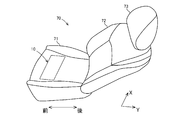
- the sensor unit 10 is disposed inside the seat surface 71 in front of the seat 70. Specifically, the sensor unit 10 is disposed on the back surface side of the skin in front of the seating surface 71. In the present embodiment, the sensor unit 10 is disposed on the seating surface 71 such that the extending direction of the second electrode 12 coincides with the front-rear direction of the seat 70.
- the sensor unit 10 is disposed in a range corresponding to the left and right thighs. That is, the sensor unit 10 receives body pressure by the left and right thighs of the person who is seated.
- the extending direction of the second electrode 12 coincides with the extending direction of the thigh, and further the extending direction of the femoral artery. That is, the sensor unit 10 is affected by the pulse wave and respiratory component of the femoral artery.
- the sensor unit 10 may be disposed on the rear surface of the seat surface 71, the rear surface 72, and the headrest 73 in addition to the front surface of the seat surface 71 of the seat 70.
- the sensor unit 10 receives body pressure from the back of the person and is affected by arterial pulse waves and respiratory components in the human buttocks.
- the sensor unit 10 receives body pressure from the back of the person and is affected by arterial pulse waves and respiratory components on the back of the person.
- the sensor unit 10 is disposed on the headrest 73, the sensor unit 10 receives body pressure from a human head, and is affected by, for example, arterial pulse waves and respiratory components in the neck.
- the power supply device 20 generates a predetermined voltage and applies the predetermined voltage to the first electrode 11 of the sensor unit 10.
- the input side circuit 30 is composed of a plurality of switches. One end of each switch is connected to the power supply device 20, and the other end of each switch is connected to the corresponding first electrode 11.
- the switches corresponding to the first electrodes 11 in the third to sixth rows from the front side are turned on, and the others are turned off. In this state, a predetermined voltage is applied to the first electrodes 11 in the third to sixth rows from the front side.
- the output side circuit 40 includes a plurality of switches. One end of each switch is connected to the corresponding second electrode 12, and the other end of each switch is connected to the arithmetic device 60 described later. In FIG. 1, the switch corresponding to the second electrode 12 in the sixth column from the left side is turned on, and the others are turned off.
- the switching device 50 performs ON / OFF switching of each switch of the input side circuit 30 and the output side circuit 40. Then, the switching device 50 connects the pressure sensor cell 10a to be measured to the power supply device 20 and the arithmetic device 60. Details of the execution process by the switching device 50 will be described later.
- the calculation device 60 acquires a detection value by the pressure sensor cell 10a to be measured, and calculates a body pressure distribution, a pulse wave and a respiratory component of the body facing the pressure sensor cell 10a based on the detection value.
- the computing device 60 includes a detected value acquisition unit 61, a body pressure distribution computing device 62 that computes a body pressure distribution, and a pulse wave and respiratory component computing device 63 that computes a pulse wave and a respiratory component.
- the detection value acquisition unit 61 acquires information on the execution process by the switching device 50 and also acquires the detection value by the sensor unit 10 in each execution state. That is, the detection value acquisition unit 61 acquires a change in capacitance of the pressure sensor cell 10a to be measured.
- the body pressure distribution calculating device 62 calculates a body pressure distribution by acquiring a change in capacitance of the pressure sensor cell 10a to be measured for body pressure distribution and calculating an external force at the position of each pressure sensor cell 10a. .
- the pulse wave and respiratory component calculation device 63 acquires a change in capacitance of the pressure sensor cell 10a to be measured for the pulse wave and respiratory component, and calculates a change in force received by the influence of the pulse wave. Calculate the wave. Furthermore, the pulse wave and respiratory component calculation device 63 obtains a change in capacitance of the pressure sensor cell 10a and calculates a change in force due to the influence of respiration, thereby calculating a respiratory component. Details of the body pressure distribution calculating device 62 and the pulse wave and respiratory component calculating device 63 will be described later.
- the execution process of the switching device 50 will be described with reference to FIG.
- the switching device 50 performs switching between the input side circuit 30 and the output side circuit 40.
- the pressure sensor cell 10a for the purpose of measuring body pressure distribution
- the pressure sensor cell 10a for the purpose of measuring pulse waves and respiratory components. Is different.
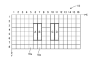
- FIG. 4 shows 128 pressure sensor cells 10a arranged in a planar and matrix form.
- the coordinate values of each axis are shown in the X direction and the Y direction.
- (16, 8) is described below, the lower right position in FIG. 16 means a position where the Y coordinate is 8.
- each of all 128 pressure sensor cells 10a located in a matrix is a measurement target. That is, in the case of measuring body pressure distribution, the switching device 50 sets the input side circuit 30 and the output side circuit 40 so that each of the 128 pressure sensor cells 10a functions as an individual sensor (first sensor). Switch.
- each sensor functioning for the purpose of measuring body pressure distribution is referred to as a first sensor. That is, in the present embodiment, when the purpose is to measure body pressure distribution, the sensor unit 10 has 128 first sensors.
- a mode in which the switching device 50 functions as the first sensor is referred to as a first mode.
- the input side circuit 30 and the output side circuit 40 are switched so that two or more pressure sensor cells 10a function as one sensor (second sensor).
- second sensor each sensor that functions when measuring the pulse wave and the respiratory component.
- each of “A”, “B”, “C”, and “D” is a part that functions as a second sensor for the purpose of measuring pulse waves and respiratory components. That is, the sensor unit 10 has four second sensors. A mode in which the switching device 50 functions as the second sensor is referred to as a second mode.
- the body pressure distribution calculation device 62 can calculate the body pressure distribution by obtaining a single detection value of each of the first sensors in a state where the body pressure is received.
- the body pressure distribution calculating device 62 can grasp the change in the body pressure distribution by acquiring the detection values of each first sensor a plurality of times. That is, the measurement cycle required for body pressure distribution measurement is not so high. Therefore, even if the measurement is not performed with a high period for 128 first sensors, changes in the body pressure distribution can be sufficiently grasped.
- the pulse wave is generally 50 to 100 times per minute, and more often 100 times or more per minute. And in order to measure a pulse wave, it is necessary to acquire the detection value of the 2nd sensor in a period shorter than the period of a pulse wave.
- the respiration rate is generally 10 to 20 times per minute. That is, the pulse wave and respiratory component calculation device 63 cannot calculate the pulse wave and respiratory component unless it acquires the detection value of the second sensor in a very short cycle.
- the measurement cycle of the pulse wave and the respiratory component by the second sensor must be extremely shorter than the measurement cycle of the body pressure distribution by the first sensor.
- the switching device 50 functions as two or more pressure sensor cells 10 a indicated by “A” from the cycle when the pressure sensor cell 10 a of (1, 1) is functioned as the first sensor. Control to shorten the period when
- the calculation device 60 includes the detection value acquisition unit 61, the body pressure distribution calculation device 62, and the pulse wave and respiratory component calculation device 63.
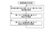
- the detection value acquisition unit 61 acquires detection values in the first mode and the second mode that are executed while switching (S1). That is, the switching device 50 has a first mode in which each of the 128 pressure sensor cells 10a functions as an individual first sensor, and a second mode in which each of the pressure sensor cells 10A to “D” functions as a second sensor.
- the detection value acquisition unit 61 acquires the respective detection values when switching between and.
- the body pressure distribution calculation device 62 calculates body pressure at each position of the 128 pressure sensor cells 10a based on the detection value in the first mode (S2). That is, the body pressure distribution calculation device 62 calculates the electrostatic pressure of each of the 128 pressure sensor cells 10a, and calculates the body pressure at each position. Then, the body pressure distribution calculating device 62 obtains the body pressure distribution in the sensor unit 10.
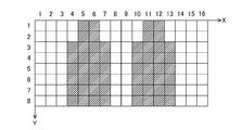
- the body pressure distribution obtained by the body pressure distribution calculation device 62 is indicated by hatching in FIG.
- the position where the body pressure is equal to or greater than the threshold value is hatched.
- the detection value about the 1st sensor of the same position is acquired again, the body pressure in the said position will be updated. That is, the body pressure distribution is updated according to the measurement period of the body pressure distribution.
- the pulse wave and respiratory component calculation device 63 calculates the pulse wave and respiratory component based on the detected values of “A” to “D” in the second mode (S3). However, since the pulse wave is very small vibration, the capacitance that changes due to the influence of the pulse wave is small. Further, since the amount of fluctuation in body pressure due to respiration is very small, the capacitance that changes due to the influence of respiration is also small. Note that the change in capacitance due to the pulse wave is even smaller than the change in capacitance due to respiration. Therefore, the pulse wave and respiratory component computing device 63 performs processing for removing components other than the pulse wave and respiratory based on the detected value so that the pulse wave and respiratory component can be measured. Details of this processing will be described later.
- the detection values of four second sensors are used, but the detection values of one second sensor may be used.
- the pulse wave and respiratory component calculation device 63 can also select the detection value of the second sensor that can most detect the pulse wave and the respiratory component among the detection values of the four second sensors. Further, the pulse wave and respiratory component computing device 63 may output all of the pulse wave and respiratory component waveforms obtained from the detection values of the four second sensors.
- the sensor unit 10 includes 128 first sensors in the first mode and four second sensors in the second mode. In one cycle of measurement, one measurement by each of 128 first sensors and a plurality of measurements by each of four second sensors are performed.
- the switching device 50 switches the input side circuit 30 and the output side circuit 40 to switch the pressure sensor cell 10a to be measured.
- the cycle Ta of one cycle is 4 ms, for example. That is, the frequency of one cycle of measurement is 250 Hz.
- the switching device 50 sequentially executes the first mode that functions as individual first sensors once in a cycle.
- the switching device 50 sequentially executes (1, 1) ⁇ (1,2) ⁇ ... ⁇ (16,7) ⁇ (16,8) as the first mode in one cycle. That is, the measurement cycle Ta by the same first sensor is 4 ms, which is the same as the cycle Ta of one cycle.
- the switching device 50 sequentially executes the second mode that functions as the second sensors “A” to “D” in one cycle. More specifically, the switching device 50 sequentially executes a second mode that functions as each second sensor in a single cycle, a plurality of times at a predetermined period.
- the switching device 50 executes in the order of “A” ⁇ “B” ⁇ “C” ⁇ “D” and repeats the process twice or more in one cycle. In the present embodiment, the switching device 50 executes the process of “A” ⁇ “B” ⁇ “C” ⁇ “D” 16 times. Therefore, the measurement cycle Tb by the same second sensor is 0.25 ms. That is, the measurement frequency by the same second sensor is 4 kHz.
- the second mode is executed with a constant second mode reference period Tc. That is, the measurement intervals of the second sensors “A” and “B”, the measurement intervals of the second sensors “B” and “C”, the measurement intervals of the second sensors “C” and “D”, and the second sensor “D” , “A” is measured at the same second mode reference period Tc. Since there are four types of second sensors, the second mode reference period Tc is 0.0625 ms. That is, the reference frequency in the second mode is 16 kHz.
- the measurement cycle Tb by the second sensor is set to a half or less of the predetermined noise cycle.
- the noise here is, for example, high-order harmonic noise derived from a power supply, and includes a 20th-order harmonic noise of about 1.2 kHz in a 60 Hz power supply.
- the period is 0.5 ms. Therefore, the measurement cycle Tb by the second sensor is set to 0.25 ms.
- the pulse wave and respiratory component calculation device 63 includes a one-cycle addition unit 631, a 37-cycle addition unit 632, a first difference calculation unit 633, a respiratory component storage unit 634, a second difference calculation unit 635, A pulse wave storage unit 636 is provided.
- the 1-cycle addition unit 631 acquires the detection value by the second sensor “A” as the primary signal E at a predetermined sampling period Tb.
- the predetermined sampling period Tb is 0.25 ms. That is, the 1-cycle addition unit 631 stores the detected value of the second sensor “A” measured every 0.25 ms as the primary signal E.
- the behavior of the primary signal E is the data shown in FIG. 10A. That is, the primary signal E contains a great deal of noise.
- the 1-cycle addition unit 631 adds the primary signal E of “A” for one cycle.
- measurement by the second sensor “A” is performed 16 times.
- a cycle Ta of one cycle is 4 ms. That is, the 1-cycle addition unit 631 adds the detection values for 16 times by the second sensor “A” in the period of 4 ms.
- the 1-cycle addition unit 631 similarly adds the second sensors “B” to “D”. Then, the 1-cycle addition unit 631 stores the data of each cycle for each of the second sensors “A” to “D”.
- the 37-cycle addition unit 632 adds the data for one cycle obtained by the one-cycle addition unit 631 for 37 consecutive cycles.
- the data added for 37 cycles is stored as the secondary signal Sum (n). That is, the 37-cycle addition unit 632 adds the detection values (primary signal E) for 592 times by the second sensor of “A” included in the period of 148 ms (first time length N) to obtain the secondary signal Sum ( n).
- the 37-cycle addition unit 632 sequentially generates the secondary signal Sum (n) while shifting the second time interval a (a ⁇ N).
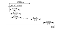
- the second time interval a is one cycle. That is, the second time interval “a” is 4 ms. Therefore, as shown in FIG. 9, secondary signals Sum (1), Sum (2), Sum (3),..., Sum (n) are generated while shifting by one cycle.
- the 37-cycle addition unit 632 generates secondary signals Sum (n) for the second sensors “B” to “D”.
- the second time interval a is set to be equal to or less than the first time length N corresponding to 37 cycles.
- the second time interval a may be sufficiently shorter than the first time length N corresponding to 37 cycles.
- the noise of the behavior of the secondary signal Sum (n) is greatly reduced as compared with the primary signal E as shown in FIG. 10B.
- a noise component equal to or less than half of the measurement cycle Tb by the second sensor is removed by the addition process.
- the secondary signal Sum (n) a component that changes in a short cycle represents a change due to a pulse wave, and a long-cycle vibration represents a change due to respiration. That is, the secondary signal Sum (n) is a signal representing a pulse wave and a respiratory component.
- a circled portion (a portion recessed downward) corresponds to a pulse wave
- an arrow portion (a portion protruding greatly upward) corresponds to a respiratory component. It is. That is, at a predetermined time, the number of circled portions is a pulse rate, and the number of arrows is a respiratory rate.
- the first difference calculation unit 633 and the second difference calculation unit 635 are tertiary, which is a difference between two secondary signals Sum (n) shifted by a third time interval M1, M2 (M1, M2 ⁇ a) (not shown).
- the signals Sig3_1 and Sig3_2 are calculated.
- the first difference calculation unit 633 calculates the tertiary signal Sig3_1 that is the difference between the immediately preceding two secondary signals Sum (m) and Sum (m-1). That is, the tertiary signal Sig3_1 has a time interval of one cycle (equal to the second time interval a) as the third time interval M1, that is, two secondary signals Sum (m) and Sum (m ⁇ 1) The difference.
- the behavior of the tertiary signal Sig3_1 computed by the first difference computation unit 633 is not so different from the behavior of the secondary signal Sum (n) as shown in FIG. 10C. That is, the tertiary signal Sig3_1 is a signal representing a pulse wave and a respiratory component. Specifically, in FIG. 10C, a circled portion (a portion recessed downward) corresponds to a pulse wave, and an arrow portion (a portion protruding greatly upward) corresponds to a respiratory component. It is.
- the absolute value of the tertiary signal Sig3_1 is smaller than that of the secondary signal Sum (n). Therefore, the tertiary signal Sig3_1 has a smaller data capacity than the secondary signal Sum (n), and can perform high-speed processing.
- the second difference calculation unit 635 calculates a tertiary signal Sig3_2 that is a difference between two secondary signals Sum (m) and Sum (1) that are shifted by a relatively long time.
- the third time interval M2 is sufficiently longer than the third time interval M1 used in the first difference calculation unit 633.
- the third time interval M2 is 250 ms. 250 ms is a quarter of the pulse wave if a general pulse wave is about 1 Hz. That is, the third time interval M2 is equal to a period corresponding to about half of the maximum amplitude of the pulse wave. Therefore, the difference between the two secondary signals Sum (m) and Sum (1) shifted by the third time interval M2 has a relatively large effect of extracting the influence of the pulse wave.
- the behavior of the tertiary signal Sig3_2 calculated by the second difference calculation unit 635 is as shown in FIG. 10D.
- a circled portion (a portion recessed downward) is a portion corresponding to a pulse wave
- an arrow portion (a portion protruding greatly upward) is a portion corresponding to a respiratory component.
- the tertiary signal Sig3_2 has a change due to the pulse wave with respect to the change in respiration.
- the absolute value of the tertiary signal Sig3_2 is smaller than that of the secondary signal Sum (n). Therefore, the tertiary signal Sig3_1 has a smaller data capacity than the secondary signal Sum (n), and can perform high-speed processing.
- the respiratory component storage unit 634 stores the tertiary signal Sig3_1 calculated by the first difference calculation unit 633 as data representing the respiratory component (FIG. 10C).
- the operator can obtain the respiratory rate by counting the number of long-period vibrations in the tertiary signal Sig3_1 stored in the respiratory component storage unit 634.
- the pulse wave storage unit 636 stores the tertiary signal Sig3_2 calculated by the second difference calculation unit 635 as data representing a pulse wave (FIG. 10D).
- the operator can obtain the pulse rate by counting the number of times corresponding to the pulse wave in the tertiary signal Sig3_2 stored in the pulse wave storage unit 636.
- the pulse wave storage unit 636 stores the tertiary signal Sig3_2 calculated by the second difference calculation unit 635 as data representing a pulse wave.
- the tertiary signal Sig3_1 calculated by the first difference calculation unit 633 represents not only a change due to respiration but also a change due to a pulse wave. Therefore, the respiratory component storage unit 634 may store data representing respiratory components and pulse waves.
- the pulse wave and respiratory component calculation device 63 has a configuration in which the second difference calculation unit 635 and the pulse wave storage unit 636 do not exist.
- the respiratory component storage unit 634 merely stores the tertiary signal Sig3_1, but in addition to this, a function of counting the respiratory rate based on the tertiary signal Sig3_1 can be added. That is, the respiratory component storage unit 634 can obtain the respiratory rate by counting the number of long-period vibrations in the tertiary signal Sig3_1.
- the pulse wave storage unit 636 merely stores the tertiary signal Sig3_2, but in addition to this, a function of counting the pulse rate based on the tertiary signal Sig3_2 can be added. That is, the pulse wave storage unit 636 can obtain the pulse rate by counting the number of times corresponding to the pulse wave in the tertiary signal Sig3_2. The pulse wave storage unit 636 may count the pulse rate based on the tertiary signal Sig3_1 calculated by the first difference calculation unit 633.
- the pulse wave storage unit 636 and the respiratory component storage unit 634 may store the secondary signal Sum (n) as data representing the pulse wave and the respiratory component, and the pulse rate based on the secondary signal Sum (n). And the respiratory rate may be counted.
- the secondary signal Sum (n) since the secondary signal Sum (n) has a large data capacity, a storage device or a processing device corresponding to the capacity is required.
- the measuring device 1 in the above embodiment includes a pressure sensor cell 10a formed in a planar shape, and an arithmetic device 60 that calculates biological information on the body facing the pressure sensor cell 10a based on a detection value by the pressure sensor cell 10a.
- the arithmetic device 60 acquires the detection value by the pressure sensor cell 10a as the primary signal E at the measurement cycle (predetermined sampling cycle) Tb by the second sensor.
- the arithmetic unit 60 calculates the secondary signal Sum (n), which is an added value of the primary signal E included in the first time length N (time length for 37 cycles), and the secondary signal Sum (n ) Are sequentially executed while shifting by the second time interval a (a ⁇ N).
- the calculation device 60 calculates biological information based on the secondary signal Sum (n).
- the measuring device 1 calculates a secondary signal Sum (n) as an added value of the detected value of the pressure sensor cell 10a.
- the secondary signal Sum (n) as the added value corresponds to a signal from which the harmonic noise component in the primary signal E is removed. That is, the process of adding the primary signal E substantially functions as a low-pass filter. In this way, the harmonic noise component is easily removed from the biological information to be acquired. Therefore, biological information can be measured with high accuracy.
- the computing device 60 computes a tertiary signal Sig3 that is the difference between the two secondary signals Sum (n) shifted by the third time interval M (M ⁇ a), and calculates biological information based on the tertiary signal Sig3. Arithmetic.
- the absolute value of the tertiary signal Sig3 that is the difference between the two secondary signals Sum (n) is smaller than that of the secondary signal Sum (n). Therefore, the tertiary signal Sig3 has a smaller data capacity than the secondary signal Sum (n) and can perform high-speed processing.
- the tertiary signal Sig3_1 calculated by the first difference calculation unit 633 is obtained when the third time interval M is equal to the second time interval a that is a shift time for generating the secondary signal Sum (n). Signal. That is, the difference from the immediately preceding secondary signal Sum (n) is the tertiary signal Sig3_1. Accordingly, the absolute value of the tertiary signal Sig3_1 is smaller than that of the secondary signal Sum (n).
- the tertiary signal Sig3_2 calculated by the second difference calculation unit 635 is a signal when the third time interval M is longer than the first time length N that is the addition time of the secondary signal Sum (n). is there.
- the tertiary signal Sig3_2 calculated by the second difference calculation unit 635 is a signal when the third time interval M is longer than the first time length N that is the addition time of the secondary signal Sum (n). is there.
- the calculation device 60 can calculate a pulse wave and a respiratory component as biological information. That is, the first difference calculation unit 633 can reliably calculate the respiratory component. On the other hand, the second difference calculation unit 635 can reliably calculate the pulse wave. Further, the pulse wave can be calculated by the first difference calculation unit 633. Although both the respiratory component and the pulse wave are very minute vibrations, they can be reliably obtained by the above calculation processing. Note that the calculation device 60 may calculate only the pulse wave as the biological information, or may calculate only the respiratory component.
- the measurement cycle Tb (sampling cycle) by the second sensor is set to one half or less of the predetermined noise cycle.
- the predetermined noise is higher-order harmonic noise derived from a power source.
- the measuring device 1 causes each of the pressure sensor cells 10a to function as an individual first sensor in one cycle that is two or more pressure sensor cells 10a arranged in a planar shape and a cycle Ta that is longer than the sampling cycle Tb.
- a switching device 50 that sequentially executes the first mode and further executes a second mode in which two or more pressure sensor cells 10a function as one second sensor.
- the arithmetic device 60 calculates the body pressure distribution of the body facing the pressure sensor cell 10a based on the detection values of the first sensor in the first mode, and uses the detection values of the second sensor in the second mode. Based on this, the biological information of the body is calculated.
- Detected values by individual pressure sensor cells 10a are used for the calculation of the body pressure distribution.
- a detection value when two or more pressure sensor cells 10a are functioned as one sensor is used.
- the amplitude of body pressure is larger than the amplitude of biological information. Therefore, one pressure sensor cell 10a is sufficient to detect pressure fluctuations due to body pressure. Therefore, at the time of body pressure measurement, the body pressure distribution can be measured with high resolution by using the detection value of each pressure sensor cell 10a.
- a small region such as one pressure sensor cell 10a is not sufficient for detecting pressure fluctuations due to biological information. Therefore, when detecting pressure fluctuation due to biological information, a detection value obtained when two or more pressure sensor cells 10a function as one second sensor is used. That is, at the time of measuring biological information, the detection area by the second sensor is enlarged so that it is easily affected by biological information that is minute vibration. Thereby, biological information which is minute vibration can be measured with high accuracy.
- the pressure sensor cell 10a is disposed between the first electrode 11, the second electrode 12 facing the first electrode 11, and the first electrode 11 and the second electrode 12, and is elastically deformed in accordance with fluctuations in biological information.
- the capacitance type sensor provided with the dielectric layer 13 is formed.
- the pressure sensor cell 10a can detect fluctuations in body pressure and biological information.
- the capacitance between the electrodes is proportional to the area of the electrodes facing each other. Therefore, when the opposing electrode area is small, the detected capacitance is small. That is, a large capacitance can be detected by configuring the second sensor for measuring biological information by two or more pressure sensor cells 10a. As a result, as described above, the biological information can be measured with high accuracy by the second sensor.
- Body pressure distribution and biological information measuring device 10: sensor unit, 10a: pressure sensor cell, 11: first electrode, 12: second electrode, 13: dielectric layer, 20: power supply device, 30: input side circuit, 40: output side circuit, 50: switching device, 60: arithmetic device, 61: detected value acquisition unit, 62: body pressure distribution arithmetic device, 63: arithmetic device for pulse wave and respiratory component, 70: seat, 71: seat surface , 72: back surface, 73: headrest, 631: 1 cycle addition unit, 632: 37 cycle addition unit, 633: first difference calculation unit, 634: respiratory component storage unit, 635: second difference calculation unit, 636: pulse wave Storage unit, E: primary signal, Sum (n): secondary signal, Sig3: tertiary signal, Sig3_1: tertiary signal by first difference calculation unit, Sig3_2: tertiary signal by second difference calculation unit, a: second M1: third time interval, M1: third time interval, M
Landscapes
- Health & Medical Sciences (AREA)
- Life Sciences & Earth Sciences (AREA)
- Physics & Mathematics (AREA)
- Molecular Biology (AREA)
- Animal Behavior & Ethology (AREA)
- Veterinary Medicine (AREA)
- Biophysics (AREA)
- Pathology (AREA)
- Engineering & Computer Science (AREA)
- Biomedical Technology (AREA)
- Heart & Thoracic Surgery (AREA)
- Medical Informatics (AREA)
- Public Health (AREA)
- Surgery (AREA)
- General Health & Medical Sciences (AREA)
- Physiology (AREA)
- General Physics & Mathematics (AREA)
- Oral & Maxillofacial Surgery (AREA)
- Dentistry (AREA)
- Cardiology (AREA)
- Pulmonology (AREA)
- Measurement Of The Respiration, Hearing Ability, Form, And Blood Characteristics Of Living Organisms (AREA)
- Measuring Pulse, Heart Rate, Blood Pressure Or Blood Flow (AREA)
- Measuring And Recording Apparatus For Diagnosis (AREA)
- Force Measurement Appropriate To Specific Purposes (AREA)
Abstract
簡易な構成で生体情報を高精度に計測する生体情報計測装置を提供する。計測装置(1)は、面状に形成される圧力センサセル(10a)と、圧力センサセル(10a)による検出値に基づいて圧力センサセル(10a)に面する身体の生体情報を演算する演算装置(60)とを備える。演算装置(60)は、所定のサンプリング周期(Tb)で圧力センサセル(10a)による検出値を一次信号(E)として取得する。演算装置(60)は、続いて、第一時間長Nに含まれる一次信号(E)の加算値である二次信号(Sum(n))を演算すると共に、二次信号(Sum(n))の演算を第二時間間隔a(a≦N)ずつずらしながら順次実行する。さらに、演算装置(60)は、二次信号(Sum(n))に基づいて生体情報を演算する。
Description
本発明は、生体情報計測装置に関するものである。
特開2015-188698号公報には、体圧分布情報と呼吸周期相当の圧力変動分布情報に基づいて、圧力検出素子群の中から心拍測定用素子を選定し、選定された素子によって心拍周期相当の圧力変動を検出することが記載されている。
特許第4864497号公報には、生体のそれぞれ異なる部分で振動を測定し、それぞれ測定された振動の強度を周波数毎に算出し、それぞれ算出された振動の強度を周波数毎に加算し、加算された振動の強度が閾値以上となった各周波数を心拍情報として検出することが記載されている。
本発明は、従来とは異なる方法により、簡易な構成で生体情報を高精度に計測する生体情報計測装置を提供することを目的とする。
生体情報計測装置は、面状に形成される圧力センサセルと、前記圧力センサセルによる検出値に基づいて、前記圧力センサセルに面する身体の生体情報を演算する演算装置とを備える。前記演算装置は、所定のサンプリング周期Tbで前記静電容量型センサによる検出値を一次信号として取得し、第一時間長Nに含まれる前記一次信号の加算値である二次信号を演算すると共に、前記二次信号の演算を第二時間間隔a(a≦N)ずつずらしながら順次実行し、前記二次信号に基づいて前記生体情報を演算する。
当該装置は、圧力センサセルの検出値の加算値としての二次信号を演算している。加算値としての二次信号は、一次信号の中の高調波ノイズ成分を除去した信号に相当する。つまり、一次信号を加算する処理が、実質的に、ローパスフィルタとして機能する。このように、取得対象の生体情報より高調波ノイズ成分が容易に除去される。従って、高精度に生体情報を計測できる。
<1.実施形態>
(1-1.体圧分布及び生体情報の計測装置1の構成)
体圧分布及び生体情報の生体情報計測装置1(以下、計測装置と称する)の構成について、図1-図3を参照して説明する。計測装置1は、面状に形成されたセンサユニット10の付与された身体の体圧分布及び生体情報を計測する。本実施形態における計測装置1は、生体情報として、脈波及び呼吸成分を計測する。計測装置1は、センサユニット10、電源装置20、入力側回路30、出力側回路40、切替装置50、及び、演算装置60を備える。
(1-1.体圧分布及び生体情報の計測装置1の構成)
体圧分布及び生体情報の生体情報計測装置1(以下、計測装置と称する)の構成について、図1-図3を参照して説明する。計測装置1は、面状に形成されたセンサユニット10の付与された身体の体圧分布及び生体情報を計測する。本実施形態における計測装置1は、生体情報として、脈波及び呼吸成分を計測する。計測装置1は、センサユニット10、電源装置20、入力側回路30、出力側回路40、切替装置50、及び、演算装置60を備える。
センサユニット10は、可撓性を有し、面状に形成される。センサユニット10は、面法線方向に、圧縮変形可能である。例えば、センサユニット10は、図2に示すように、8列の第一電極11と、16列の第二電極12と、誘電層13とを備える。なお、第一電極11と第二電極12の列数は、適宜変更可能である。
第一電極11は、帯状に形成され、相互に平行に配置される。第二電極12は、センサユニット10の面法線方向に、第一電極11に対して距離を隔てて配置される。第二電極12は、帯状に形成され、相互に平行に配置される。第二電極12の延在方向は、第一電極11の延在方向に対して直交する方向である。誘電層13は、弾性変形可能な面状に形成され、第一電極11と第二電極12との間に配置される。
第一電極11及び第二電極12は、エラストマー中に導電性フィラーを配合させることにより成形される。第一電極11及び第二電極12は、可撓性を有し、伸縮自在な性質を有する。第一電極11及び第二電極12を構成するエラストマーには、例えば、シリコーンゴム、エチレン-プロピレン共重合ゴム、天然ゴム、スチレン-ブタジエン共重合ゴム、アクリロニトリル-ブタジエン共重合ゴム、アクリルゴム、エピクロロヒドリンゴム、クロロスルホン化ポリエチレン、塩素化ポリエチレン、ウレタンゴムなどが適用される。また、第一電極11及び第二電極12に配合される導電性フィラーには、導電性を有する粒子であればよく、例えば、炭素材料や金属等の微粒子が適用される。
誘電層13は、エラストマーにより成形され、可撓性を有し且つ伸縮自在な性質を有する。誘電層13を構成するエラストマーには、例えば、シリコーンゴム、アクリロニトリル-ブタジエン共重合ゴム、アクリルゴム、エピクロロヒドリンゴム、クロロスルホン化ポリエチレン、塩素化ポリエチレン、ウレタンゴムなどが適用される。
従って、第一電極11と第二電極12との交差位置がマトリックス状に位置する。センサユニット10は、マトリックス状の電極交差位置において、静電容量型センサとして機能する圧力センサセル10aを備える。本実施形態においては、センサユニット10は、横16列、縦8列に配列された128個の圧力センサセル10aを備える。そして、128個の圧力センサセル10aが、面状に配列されている。
そして、センサユニット10が面法線方向に圧縮する力を受けた場合には、誘電層13が圧縮変形することにより、第一電極11と第二電極12の離間距離が短くなる。つまり、第一電極11と第二電極12との間の静電容量が大きくなる。
ここで、センサユニット10は、図3に示すように、例えば、シート70の座面71前方の内部に配置される。詳細には、センサユニット10は、座面71前方の表皮の裏面側に配置される。本実施形態においては、センサユニット10は、第二電極12の延在方向がシート70の前後方向に一致するように、座面71に配置される。また、センサユニット10は、左右の大腿部に相当する範囲に配置される。つまり、センサユニット10は、着座する人の左右の大腿部によって、体圧を受ける。そして、第二電極12の延在方向は、大腿部の延在方向、さらには、大腿動脈の延在方向に一致する。つまり、センサユニット10は、大腿動脈の脈波や呼吸成分の影響を受ける。
なお、センサユニット10は、シート70の座面71前方の他に、座面71後方、背面72やヘッドレスト73に配置してもよい。センサユニット10が座面後方に配置される場合は、センサユニット10は、人の背部により体圧を受け、人の臀部における動脈の脈波や呼吸成分の影響を受ける。また、背面72に配置される場合には、センサユニット10は、人の背部により体圧を受け、人の背部における動脈の脈波や呼吸成分の影響を受ける。また、センサユニット10がヘッドレスト73に配置される場合には、センサユニット10は、人の頭部により体圧を受け、例えば首部における動脈の脈波や呼吸成分の影響を受ける。
電源装置20は、所定の電圧を発生し、センサユニット10の第一電極11に対して所定電圧を印加する。
入力側回路30は、複数のスイッチにより構成される。各スイッチの一端は、電源装置20に接続されており、各スイッチの他端は、対応する第一電極11に接続される。図1においては、前側から3列目から6列目までの第一電極11に対応するスイッチがONされ、他はOFFされている。この状態では、前側から3列目から6列目までの第一電極11に、所定電圧が印加される。
出力側回路40は、複数のスイッチにより構成される。各スイッチの一端は、対応する第二電極12に接続され、各スイッチの他端は、後述する演算装置60に接続される。図1においては、左側から6列目の第二電極12に対応するスイッチがONされ、他はOFFされている。
切替装置50は、入力側回路30及び出力側回路40の各スイッチのON/OFFの切替を実行する。そして、切替装置50は、計測対象とする圧力センサセル10aを、電源装置20及び演算装置60に接続させる。なお、切替装置50による実行処理の詳細は、後述する。
演算装置60は、計測対象の圧力センサセル10aによる検出値を取得して、当該検出値に基づいて圧力センサセル10aに面する身体の体圧分布、脈波及び呼吸成分を演算する。演算装置60は、検出値取得部61と、体圧分布を演算する体圧分布演算装置62と、脈波と呼吸成分を演算する脈波と呼吸成分の演算装置63とを備える。
検出値取得部61は、切替装置50による実行処理の情報を取得すると共に、各実行状態におけるセンサユニット10による検出値を取得する。つまり、検出値取得部61は、計測対象の圧力センサセル10aの静電容量の変化を取得する。
体圧分布演算装置62は、体圧分布の計測対象の圧力センサセル10aの静電容量の変化を取得して、個々の圧力センサセル10aの位置における外力を演算することで、体圧分布を演算する。脈波と呼吸成分の演算装置63は、脈波と呼吸成分の計測対象の圧力センサセル10aの静電容量の変化を取得して、脈波の影響により受ける力の変化を演算することで、脈波を演算する。さらに、脈波と呼吸成分の演算装置63は、当該圧力センサセル10aの静電容量の変化を取得して、呼吸の影響により受ける力の変化を演算することで、呼吸成分を演算する。体圧分布演算装置62及び脈波と呼吸成分の演算装置63の詳細は、後述する。
(1-2.切替装置50の実行処理)
切替装置50の実行処理について、図4を参照して説明する。切替装置50は、入力側回路30及び出力側回路40の切り替えを実行する。ここで、マトリックス状に位置する128個の圧力センサセル10aの中で、体圧分布計測を目的とする場合における圧力センサセル10aと、脈波及び呼吸成分の計測を目的とする場合における圧力センサセル10aとは、異なる。
切替装置50の実行処理について、図4を参照して説明する。切替装置50は、入力側回路30及び出力側回路40の切り替えを実行する。ここで、マトリックス状に位置する128個の圧力センサセル10aの中で、体圧分布計測を目的とする場合における圧力センサセル10aと、脈波及び呼吸成分の計測を目的とする場合における圧力センサセル10aとは、異なる。
図4には、面状且つマトリックス状に配列される128個の圧力センサセル10aが示される。図4において、X方向及びY方向には、各軸の座標値が示されており、以下において、(16,8)と記載した場合には、図4の右下の位置、すなわちX座標が16であり、Y座標が8である位置を意味する。
体圧分布計測を目的とする場合において、マトリックス状に位置する128個全ての圧力センサセル10aのそれぞれが計測対象となる。つまり、体圧分布計測を目的とする場合において、切替装置50は、128個の圧力センサセル10aそれぞれを個々のセンサ(第一センサ)として機能させるように、入力側回路30及び出力側回路40を切り替える。以下において、体圧分布計測を目的とする場合に機能する個々のセンサを、第一センサと称する。つまり、本実施形態において、体圧分布計測を目的とする場合において、センサユニット10は、128個の第一センサを有することになる。また、切替装置50により第一センサとして機能させるモードを、第一モードと称する。
一方、脈波及び呼吸成分の計測を目的とする場合において、マトリックス状に位置する全ての圧力センサセル10aが計測対象でなく、一部の圧力センサセル10aのみが計測対象となる。そして、脈波及び呼吸成分の計測を目的とする場合において、二個以上の圧力センサセル10aを一個のセンサ(第二センサ)として機能させるように、入力側回路30及び出力側回路40を切り替える。以下において、脈波及び呼吸成分の計測を目的とする場合に機能する個々のセンサを、第二センサと称する。
本実施形態においては、図4において、「A」「B」「C」「D」で示されるそれぞれが、脈波及び呼吸成分の計測を目的とする第二センサとして機能する部位である。つまり、センサユニット10は、4個の第二センサを有することになる。また、切替装置50により第二センサとして機能させるモードを、第二モードと称する。
(1-3.体圧分布、脈波、呼吸成分における計測周期)
次に、第一センサによる体圧分布の計測周期と、第二センサによる脈波及び呼吸成分の計測周期について、説明する。
次に、第一センサによる体圧分布の計測周期と、第二センサによる脈波及び呼吸成分の計測周期について、説明する。
体圧分布計測を目的とする場合には、体圧を受けていない状態の第一センサの検出値と、体圧を受けた状態の第一センサの検出値とを取得すれば足りる。従って、体圧分布演算装置62は、体圧を受けた状態において、個々の第一センサの1回の検出値を取得すれば、体圧分布を演算することができる。
ここで、体圧分布演算装置62は、個々の第一センサの複数回の検出値を取得することで、体圧分布の変化を把握することができる。つまり、体圧分布計測に要求される計測周期は、それほど高いものではない。従って、128個の第一センサについて、それほど高い周期でない計測を行ったとしても、十分に体圧分布の変化を把握できる。
一方、脈波は、一般に1分間に50~100回であり、多い場合には1分間に100回以上となる。そして、脈波を計測するためには、脈波の周期に比べて格段に短い周期での第二センサの検出値を取得する必要がある。また、呼吸数は、一般に、1分間に10数回~20数回である。つまり、脈波と呼吸成分の演算装置63は、非常に短い周期での第二センサの検出値を取得しなければ、脈波及び呼吸成分を演算することはできない。
従って、第二センサによる脈波及び呼吸成分の計測周期は、第一センサによる体圧分布の計測周期より極めて短くしなければならない。図4において、切替装置50は、例えば、(1,1)の圧力センサセル10aを第一センサとして機能させる場合の周期より、「A」で示す二個以上の圧力センサセル10aを第二センサとして機能させる場合の周期を短くするように制御する。
(1-4.演算装置60の処理)
演算装置60の処理について、図5-図6を参照して説明する。演算装置60は、上述したように、検出値取得部61、体圧分布演算装置62、脈波と呼吸成分の演算装置63を備える。
演算装置60の処理について、図5-図6を参照して説明する。演算装置60は、上述したように、検出値取得部61、体圧分布演算装置62、脈波と呼吸成分の演算装置63を備える。
図5に示すように、検出値取得部61が、切り替えながら実行される第一モード及び第二モードによる検出値を取得する(S1)。つまり、切替装置50が、128個の圧力センサセル10aそれぞれを個々の第一センサとして機能させる第一モードと、「A」~「D」の圧力センサセル10aそれぞれを第二センサとして機能させる第二モードとを切り替えながら実行する場合に、検出値取得部61が、それぞれの検出値を取得する。
体圧分布演算装置62は、第一モードにおける検出値に基づいて、128個の圧力センサセル10aのそれぞれの位置における体圧を演算する(S2)。つまり、体圧分布演算装置62は、128個の圧力センサセル10aのそれぞれの静電容量を演算して、各位置における体圧を演算する。そして、体圧分布演算装置62は、センサユニット10における体圧分布を得る。
体圧分布演算装置62により得られる体圧分布は、図6にて、ハッチングにて示す。例えば、図6には、体圧が閾値以上となる位置に、ハッチングを付している。また、閾値を複数段階設定することで、体圧の強弱度合の分布を表すこともできる。そして、再び、同一位置の第一センサについての検出値を取得すると、当該位置における体圧を更新する。つまり、体圧分布の計測周期に応じて、体圧分布が更新される。
脈波と呼吸成分の演算装置63は、第二モードにおける「A」~「D」のそれぞれの検出値に基づいて、脈波及び呼吸成分を演算する(S3)。ただし、脈波は、非常に小さな振動であるため、脈波の影響により変化する静電容量も小さい。また、呼吸による体圧変動量も非常に小さいため、呼吸の影響により変化する静電容量も小さい。なお、脈波による静電容量の変化は、呼吸による静電容量の変化よりもさらに小さい。そこで、脈波と呼吸成分の演算装置63は、検出値に基づいて、脈波及び呼吸以外の成分を除去する処理を行い、脈波及び呼吸成分を計測できるようにする。この処理の詳細は、後述する。
ここで、脈波及び呼吸の演算において、4個の第二センサの検出値を用いるが、1個の第二センサの検出値を用いるようにしてもよい。例えば、脈波と呼吸成分の演算装置63は、4個の第二センサの検出値の中で、脈波及び呼吸成分を最も検出できる第二センサの検出値を選択することもできる。また、脈波と呼吸成分の演算装置63は、4個の第二センサの検出値による得られる脈波及び呼吸成分の波形の全てを出力するようにしてもよい。
(1-5.切替装置50による詳細処理)
次に、切替装置50による詳細処理について、図7を参照して説明する。上述したように、センサユニット10は、第一モードにおける128個の第一センサと、第二モードにおける4個の第二センサとを有する。計測の1サイクルにおいて、128個の第一センサのそれぞれによる1回ずつの計測と、4個の第二センサのそれぞれによる複数回の計測を行う。
次に、切替装置50による詳細処理について、図7を参照して説明する。上述したように、センサユニット10は、第一モードにおける128個の第一センサと、第二モードにおける4個の第二センサとを有する。計測の1サイクルにおいて、128個の第一センサのそれぞれによる1回ずつの計測と、4個の第二センサのそれぞれによる複数回の計測を行う。
具体的には、図7に示すように、切替装置50は、入力側回路30及び出力側回路40を切り替えて、計測対象の圧力センサセル10aを切り替える。ここで、1サイクルの周期Taは、例えば、4msである。すなわち、計測の1サイクルの周波数は、250Hzである。
切替装置50は、1サイクルにおいて、個々の第一センサとして機能させる第一モードを1回ずつ順次実行させる。切替装置50は、1サイクルにおいて、第一モードとして、(1,1)→(1,2)→・・・・→(16,7)→(16,8)を順次実行する。つまり、同一の第一センサによる計測周期Taは、1サイクルの周期Taと同一の4msとなる。
一方、切替装置50は、1サイクルにおいて、「A」~「D」の第二センサとして機能させる第二モードを順次実行させる。より詳細には、切替装置50は、1サイクルにおいて、個々の第二センサとして機能させる第二モードを、所定周期で複数回ずつ順次実行させる。切替装置50は、1サイクルにおいて、「A」→「B」→「C」→「D」の順に実行すると共に、その処理を二回以上繰り返す。本実施形態においては、切替装置50は、「A」→「B」→「C」→「D」の処理を、16回実行する。従って、同一の第二センサによる計測周期Tbは、0.25msとなる。すなわち、同一の第二センサによる計測周波数は、4kHzとなる。
さらに、第二モードは、一定の第二モード基準周期Tcで実行される。つまり、第二センサ「A」、「B」の計測間隔、第二センサ「B」、「C」の計測間隔、第二センサ「C」、「D」の計測間隔、第二センサ「D」、「A」の計測間隔は、同一の第二モード基準周期Tcとなる。第二センサが、4種類であるため、第二モード基準周期Tcは、0.0625msとなる。すなわち、第二モードの基準周波数は、16kHzとなる。
ここで、ノイズの影響を確実に除去するために、第二センサによる計測周期Tbは、所定のノイズの周期の2分の1以下に設定されている。ここでのノイズは、例えば、電源に由来する高次の高調波ノイズであり、60Hz電源では20次で1.2kHz程度の高調波ノイズを含む。最大で2kHz程度のノイズを想定した場合、当該周期は、0.5msである。そこで、第二センサによる計測周期Tbは、0.25msとしている。
(1-6.脈波と呼吸成分の演算装置63の詳細構成)
脈波と呼吸成分の演算装置63の構成について、図8、図9及び図10A-図10Dを参照して説明する。ここで、図10A-図10Dにおいて、横軸はサンプリング回数であって時間に相当し、縦軸はデータ数値である。図8に示すように、脈波と呼吸成分の演算装置63は、1サイクル加算部631、37サイクル加算部632、第一差分演算部633、呼吸成分記憶部634、第二差分演算部635、脈波記憶部636を備える。
脈波と呼吸成分の演算装置63の構成について、図8、図9及び図10A-図10Dを参照して説明する。ここで、図10A-図10Dにおいて、横軸はサンプリング回数であって時間に相当し、縦軸はデータ数値である。図8に示すように、脈波と呼吸成分の演算装置63は、1サイクル加算部631、37サイクル加算部632、第一差分演算部633、呼吸成分記憶部634、第二差分演算部635、脈波記憶部636を備える。
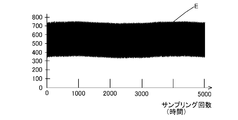
1サイクル加算部631は、所定のサンプリング周期Tbで「A」の第二センサによる検出値を一次信号Eとして取得する。ここでは、所定のサンプリング周期Tbは、0.25msである。つまり、1サイクル加算部631は、0.25ms毎に計測された「A」の第二センサによる検出値を一次信号Eとして記憶する。一次信号Eの挙動は、図10Aに示すデータである。つまり、一次信号Eは、非常に多くのノイズを含んでいる。
さらに、1サイクル加算部631は、「A」の一次信号Eを、1サイクル分、加算する。ここでは、1サイクルにおいて、「A」の第二センサによる計測は、16回実施される。1サイクルの周期Taは、4msである。つまり、1サイクル加算部631は、4msの期間における「A」の第二センサによる16回分の検出値を加算する。
また、1サイクル加算部631は、「B」~「D」の第二センサについても同様に、それぞれ加算する。そして、1サイクル加算部631は、「A」~「D」のそれぞれの第二センサについて、各サイクルのデータを、記憶しておく。
37サイクル加算部632は、1サイクル加算部631により得られた1サイクル分のデータを、連続する37サイクル分、加算する。37サイクル分加算されたデータは、二次信号Sum(n)として記憶される。つまり、37サイクル加算部632は、148msの期間(第一時間長N)に含まれる「A」の第二センサによる592回分の検出値(一次信号E)を加算して、二次信号Sum(n)を生成する。
さらに、37サイクル加算部632は、第二時間間隔a(a≦N)ずつずらしながら、二次信号Sum(n)の生成を順次実行する。本実施形態においては、第二時間間隔aは、1サイクル分としている。つまり、第二時間間隔aは、4msである。従って、図9に示すように、1サイクル分ずつずらしながら、二次信号Sum(1)、Sum(2)、Sum(3)、・・・、Sum(n)が生成される。そして、37サイクル加算部632は、「B」~「D」の第二センサについても同様に、それぞれ二次信号Sum(n)を生成する。
なお、第二時間間隔aは、37サイクル分に相当する第一時間長N以下にする。特に、高精度に脈波及び呼吸成分を計測するためには、第二時間間隔aは、37サイクル分に相当する第一時間長Nに比べて十分に短くするとよい。
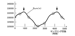
二次信号Sum(n)の挙動は、図10Bに示すように、一次信号Eに比べると、ノイズが大幅に低減している。特に、第二センサによる計測周期Tbの2分の1以下のノイズ成分は、加算処理によって、除去される。二次信号Sum(n)において、短周期に変化する成分が脈波による変化を表しており、長周期の振動が呼吸による変化を表している。つまり、二次信号Sum(n)は、脈波及び呼吸成分を表す信号となっている。具体的には、図10Bにおいて、丸印の箇所(下方に凹んでいる箇所)が脈波に対応する箇所であり、矢印の箇所(大きく上に突出している箇所)が呼吸成分に対応する箇所である。つまり、所定時間において、丸印の箇所の数が脈拍数となり、矢印の箇所の数が呼吸数となる。
第一差分演算部633、第二差分演算部635は、図略の第三時間間隔M1、M2(M1、M2≧a)だけずれた二個の二次信号Sum(n)の差分である三次信号Sig3_1、Sig3_2を演算する。
第一差分演算部633は、直前の二個の二次信号Sum(m)、Sum(m-1)の差分である三次信号Sig3_1を演算する。つまり、三次信号Sig3_1は、第三時間間隔M1として、1サイクル分の時間間隔(第二時間間隔aに等しい)、すなわち4msだけずれた二個の二次信号Sum(m)、Sum(m-1)の差分である。
第一差分演算部633により演算される三次信号Sig3_1の挙動は、図10Cに示すように、二次信号Sum(n)の挙動とそれほど変わりない。つまり、三次信号Sig3_1には、脈波及び呼吸成分を表す信号である。具体的には、図10Cにおいて、丸印の箇所(下方に凹んでいる箇所)が脈波に対応する箇所であり、矢印の箇所(大きく上に突出している箇所)が呼吸成分に対応する箇所である。ここで、三次信号Sig3_1は、二次信号Sum(n)に比べて、絶対値が小さくなっている。そのため、三次信号Sig3_1は、二次信号Sum(n)よりも、データ容量が小さく、高速処理を行うことができる。
第二差分演算部635は、相対的に長い時間だけずれた二個の二次信号Sum(m)とSum(1)の差分である三次信号Sig3_2を演算する。ここで、第三時間間隔M2は、第一差分演算部633にて用いる第三時間間隔M1よりも十分に長い。本実施形態では、第三時間間隔M2は、250msである。250msとは、一般的な脈波が1Hz程度であるとすると、その脈波の4分の1である。つまり、この第三時間間隔M2は、脈波の最大振幅の半分程度に相当する周期に等しい。従って、第三時間間隔M2だけずれた二個の二次信号Sum(m)、Sum(1)の差分は、比較的、脈波の影響分を大きく抽出する作用がある。
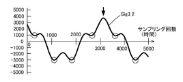
第二差分演算部635により演算される三次信号Sig3_2の挙動は、図10Dに示すような挙動となる。図10Dにおいて、丸印の箇所(下方に凹んでいる箇所)が脈波に対応する箇所であり、矢印の箇所(大きく上に突出している箇所)が呼吸成分に対応する箇所である。三次信号Sig3_2は、二次信号Sum(n)と比べると、呼吸の変化に対して脈波による変化が際立っている。さらに、三次信号Sig3_2は、二次信号Sum(n)に比べて、絶対値が小さくなっている。そのため、三次信号Sig3_1は、二次信号Sum(n)よりも、データ容量が小さく、高速処理を行うことができる。
呼吸成分記憶部634は、第一差分演算部633により演算された三次信号Sig3_1を、呼吸成分を表すデータとして記憶する(図10C)。オペレータは、呼吸成分記憶部634に記憶された三次信号Sig3_1における長周期の振動回数をカウントすることで、呼吸数を得ることができる。
脈波記憶部636は、第二差分演算部635により演算された三次信号Sig3_2を、脈波を表すデータとして記憶する(図10D)。オペレータは、脈波記憶部636に記憶された三次信号Sig3_2において脈波に対応する箇所の回数をカウントすることで、脈拍数を得ることができる。
<2.実施形態の変形態様>
上記実施形態においては、脈波記憶部636は、第二差分演算部635により演算された三次信号Sig3_2を、脈波を表すデータとして記憶した。ここで、上述したように、第一差分演算部633により演算された三次信号Sig3_1には、呼吸による変化のみならず、脈波による変化も表されている。そこで、呼吸成分記憶部634が、呼吸成分と脈波とを表すデータを記憶することとしてもよい。この場合、脈波と呼吸成分の演算装置63は、第二差分演算部635及び脈波記憶部636の存在しない構成となる。
上記実施形態においては、脈波記憶部636は、第二差分演算部635により演算された三次信号Sig3_2を、脈波を表すデータとして記憶した。ここで、上述したように、第一差分演算部633により演算された三次信号Sig3_1には、呼吸による変化のみならず、脈波による変化も表されている。そこで、呼吸成分記憶部634が、呼吸成分と脈波とを表すデータを記憶することとしてもよい。この場合、脈波と呼吸成分の演算装置63は、第二差分演算部635及び脈波記憶部636の存在しない構成となる。
また、呼吸成分記憶部634は、単に三次信号Sig3_1を記憶するだけであるが、この他に、三次信号Sig3_1に基づいて呼吸数をカウントする機能を付加することもできる。つまり、呼吸成分記憶部634は、三次信号Sig3_1における長周期の振動回数をカウントすることにより、呼吸数を得ることができる。
また、脈波記憶部636は、単に三次信号Sig3_2を記憶するだけであるが、この他に、三次信号Sig3_2に基づいて脈拍数をカウントする機能を付加することもできる。つまり、脈波記憶部636は、三次信号Sig3_2における脈波に対応する箇所の回数をカウントすることにより、脈拍数を得ることができる。なお、脈波記憶部636は、第一差分演算部633により演算された三次信号Sig3_1に基づいて、脈拍数をカウントするようにしてもよい。
また、脈波記憶部636及び呼吸成分記憶部634は、二次信号Sum(n)を脈波及び呼吸成分を表すデータとして記憶してもよく、二次信号Sum(n)に基づいて脈拍数及び呼吸数をカウントしてもよい。ただし、上述したように、二次信号Sum(n)は、データ容量が大きいため、容量に応じた記憶装置や処理装置が必要となる。
<3.実施形態の効果>
上記実施形態における計測装置1は、面状に形成される圧力センサセル10aと、圧力センサセル10aによる検出値に基づいて圧力センサセル10aに面する身体の生体情報を演算する演算装置60とを備える。演算装置60は、第二センサによる計測周期(所定のサンプリング周期)Tbで圧力センサセル10aによる検出値を一次信号Eとして取得する。演算装置60は、続いて、第一時間長N(37サイクル分の時間長)に含まれる一次信号Eの加算値である二次信号Sum(n)を演算すると共に、二次信号Sum(n)の演算を第二時間間隔a(a≦N)ずつずらしながら順次実行する。さらに、演算装置60は、二次信号Sum(n)に基づいて生体情報を演算する。
上記実施形態における計測装置1は、面状に形成される圧力センサセル10aと、圧力センサセル10aによる検出値に基づいて圧力センサセル10aに面する身体の生体情報を演算する演算装置60とを備える。演算装置60は、第二センサによる計測周期(所定のサンプリング周期)Tbで圧力センサセル10aによる検出値を一次信号Eとして取得する。演算装置60は、続いて、第一時間長N(37サイクル分の時間長)に含まれる一次信号Eの加算値である二次信号Sum(n)を演算すると共に、二次信号Sum(n)の演算を第二時間間隔a(a≦N)ずつずらしながら順次実行する。さらに、演算装置60は、二次信号Sum(n)に基づいて生体情報を演算する。
計測装置1は、圧力センサセル10aの検出値の加算値としての二次信号Sum(n)を演算している。加算値としての二次信号Sum(n)は、一次信号Eの中の高調波ノイズ成分を除去した信号に相当する。つまり、一次信号Eを加算する処理が、実質的に、ローパスフィルタとして機能する。このように、取得対象の生体情報より高調波ノイズ成分が容易に除去される。従って、高精度に生体情報を計測できる。
さらに、演算装置60は、第三時間間隔M(M≧a)だけずれた二個の二次信号Sum(n)の差分である三次信号Sig3を演算し、三次信号Sig3に基づいて生体情報を演算している。このように、二個の二次信号Sum(n)の差分である三次信号Sig3は、二次信号Sum(n)に比べると、絶対値が小さくなっている。そのため、三次信号Sig3は、二次信号Sum(n)よりも、データ容量が小さく、高速処理を行うことができる。
そして、第一差分演算部633で演算される三次信号Sig3_1は、第三時間間隔Mを、二次信号Sum(n)を生成するためのずらし時間である第二時間間隔aに等しくしたときの信号である。つまり、直前の二次信号Sum(n)との差分が、三次信号Sig3_1となる。これにより、三次信号Sig3_1は、二次信号Sum(n)に比べると、絶対値が小さくなっている。
また、第二差分演算部635で演算される三次信号Sig3_2は、第三時間間隔Mを、二次信号Sum(n)の加算時間である第一時間長Nより長い時間としたときの信号である。これにより、目的外の信号成分を除去することができ、目的の生体情報の成分を大きくすることができる。従って、目的の生体情報を確実に得ることができる。
また、演算装置60は、生体情報として脈波及び呼吸成分を演算することができる。つまり、第一差分演算部633により、確実に、呼吸成分を演算することができる。一方、第二差分演算部635により、確実に、脈波を演算することができる。また、第一差分演算部633により、脈波を演算することもできる。呼吸成分も脈波も、非常に微小な振動であるが、上記の演算処理により確実に得ることができる。なお、演算装置60は、生体情報として脈波のみを演算するようにしてもよいし、呼吸成分のみを演算するようにしてもよい。
第二センサによる計測周期Tb(サンプリング周期)は、所定のノイズ周期の2分の1以下に設定される。例えば、所定のノイズとは、電源に由来する高次の高調波ノイズなどである。第二センサによる計測周期Tbを、所定のノイズ周期の2分の1以下に設定することで、第二センサによる検出値には、確実に、所定のノイズの影響分が含まれ、ノイズの影響分と、計測目的の成分とを区別することができる。従って、確実に、生体情報を得ることができる。
また、計測装置1は、面状に配列される二個以上の圧力センサセル10aと、サンプリング周期Tbよりも長い周期Taである1サイクルにおいて、それぞれの圧力センサセル10aを個々の第一センサとして機能させる第一モードを順次実行すると共に、二個以上の圧力センサセル10aを一個の第二センサとして機能させる第二モードをさらに実行する切替装置50とを備える。そして、演算装置60は、第一モードにおける第一センサのそれぞれの検出値に基づいて、圧力センサセル10aに面する身体の体圧分布を演算すると共に、第二モードにおける第二センサの検出値に基づいて、身体の生体情報を演算する。
体圧分布の演算には、個々の圧力センサセル10aによる検出値が用いられる。一方、生体情報の演算には、二個以上の圧力センサセル10aを一個のセンサとして機能させた場合の検出値が用いられる。
体圧の振幅は、生体情報の振幅に比べて大きい。そのため、体圧による圧力変動を検出するためには、圧力センサセル10a一個であっても十分である。そこで、体圧計測の時には、個々の圧力センサセル10aの検出値を用いることで、体圧分布を高分解能で計測することができる。
一方、生体情報による圧力変動を検出するためには、圧力センサセル10a一個のような小さな領域では、十分ではない。そこで、生体情報による圧力変動を検出する際には、二個以上の圧力センサセル10aを一個の第二センサとして機能させたときの検出値を用いている。つまり、生体情報の計測の時には、第二センサによる検出領域を大きくすることにより、微小振動である生体情報の影響を受けやすい状態としている。これにより、微小振動である生体情報を、高精度に計測できる。
また、圧力センサセル10aは、第一電極11と、第一電極11に対向する第二電極12と、第一電極11と第二電極12との間に配置され生体情報の変動に伴って弾性変形する誘電層13とを備える静電容量型センサとした。これにより、圧力センサセル10aは、体圧及び生体情報の変動を検出することができる。さらに、電極間の静電容量は、対向する電極面積に比例する。そのため、対向する電極面積が小さいと、検出される静電容量が小さくなる。つまり、生体情報の計測のための第二センサが、二個以上の圧力センサセル10aにより構成されることにより、大きな静電容量を検出できる。その結果、上述したように、第二センサにより、生体情報を高精度に計測できるようになる。
1:体圧分布及び生体情報の計測装置、 10:センサユニット、 10a:圧力センサセル、 11:第一電極、 12:第二電極、 13:誘電層、 20:電源装置、 30:入力側回路、 40:出力側回路、 50:切替装置、 60:演算装置、 61:検出値取得部、 62:体圧分布演算装置、 63:脈波と呼吸成分の演算装置、 70:シート、 71:座面、 72:背面、 73:ヘッドレスト、 631:1サイクル加算部、 632:37サイクル加算部、 633:第一差分演算部、 634:呼吸成分記憶部、 635:第二差分演算部、 636:脈波記憶部、 E:一次信号、 Sum(n):二次信号、 Sig3:三次信号、 Sig3_1:第一差分演算部による三次信号、 Sig3_2:第二差分演算部による三次信号、 a:第二時間間隔、 M:第三時間間隔、 M1:第一差分演算部の処理における第三時間間隔、 M2:第二差分演算部の処理における第三時間間隔、 N:第一時間長、 Ta:第一センサによる計測周期(1サイクルの周期)、 Tb:第二センサによる計測周期(サンプリング周期)、
Tc:第二モード基準周期
Tc:第二モード基準周期
Claims (9)
- 面状に形成される圧力センサセルと、
前記圧力センサセルによる検出値に基づいて、前記圧力センサセルに面する身体の生体情報を演算する演算装置と、
を備える生体情報計測装置であって、
前記演算装置は、
所定のサンプリング周期Tbで前記圧力センサセルによる検出値を一次信号として取得し、
第一時間長Nに含まれる前記一次信号の加算値である二次信号を演算すると共に、前記二次信号の演算を第二時間間隔a(a≦N)ずつずらしながら順次実行し、
前記二次信号に基づいて前記生体情報を演算する、生体情報計測装置。 - 前記演算装置は、
第三時間間隔M(M≧a)だけずれた二個の前記二次信号の差分である三次信号を演算し、
前記三次信号に基づいて前記生体情報を演算する、請求項1に記載の生体情報計測装置。 - 前記第三時間間隔Mは、前記第二時間間隔aに等しい、請求項2に記載の生体情報計測装置。
- 前記第三時間間隔Mは、前記第一時間長Nより長い時間である、請求項2に記載の生体情報計測装置。
- 前記演算装置は、前記生体情報として脈波を演算する、請求項1-4の何れか一項に記載の生体情報計測装置。
- 前記演算装置は、前記生体情報として脈波及び呼吸成分を演算する、請求項1-3の何れか一項に記載の生体情報計測装置。
- 前記サンプリング周期Tbは、所定のノイズ周期の2分の1以下に設定される、請求項1-6の何れか一項に記載の生体情報計測装置。
- 前記生体情報計測装置は、
面状に配列される二個以上の前記圧力センサセルと、
前記サンプリング周期Tbよりも長い周期Taである1サイクルにおいて、それぞれの前記圧力センサセルを個々の第一センサとして機能させる第一モードを順次実行すると共に、二個以上の前記圧力センサセルを一個の第二センサとして機能させる第二モードをさらに実行する切替装置と、
を備え、
前記演算装置は、
前記第一モードにおける前記第一センサのそれぞれの検出値に基づいて、前記圧力センサセルに面する身体の体圧分布を演算すると共に、
前記第二モードにおける前記第二センサの検出値に基づいて、前記身体の生体情報を演算する、請求項1-7の何れか一項に記載の生体情報計測装置。 - 前記圧力センサセルは、第一電極と、前記第一電極に対向する第二電極と、前記第一電極と前記第二電極との間に配置され前記生体情報の変動に伴って弾性変形する誘電層とを備える静電容量型センサである、請求項1-8の何れか一項に記載の生体情報計測装置。
Applications Claiming Priority (2)
| Application Number | Priority Date | Filing Date | Title |
|---|---|---|---|
| JP2016-069135 | 2016-03-30 | ||
| JP2016069135A JP6608320B2 (ja) | 2016-03-30 | 2016-03-30 | 生体情報計測装置 |
Publications (1)
| Publication Number | Publication Date |
|---|---|
| WO2017169996A1 true WO2017169996A1 (ja) | 2017-10-05 |
Family
ID=59964294
Family Applications (1)
| Application Number | Title | Priority Date | Filing Date |
|---|---|---|---|
| PCT/JP2017/011294 Ceased WO2017169996A1 (ja) | 2016-03-30 | 2017-03-22 | 生体情報計測装置 |
Country Status (2)
| Country | Link |
|---|---|
| JP (1) | JP6608320B2 (ja) |
| WO (1) | WO2017169996A1 (ja) |
Cited By (1)
| Publication number | Priority date | Publication date | Assignee | Title |
|---|---|---|---|---|
| CN114052676A (zh) * | 2021-11-19 | 2022-02-18 | 南开大学 | 一种中医脉搏精简阵列传感器及其全阵列脉搏信息获取算法 |
Families Citing this family (1)
| Publication number | Priority date | Publication date | Assignee | Title |
|---|---|---|---|---|
| WO2022070802A1 (ja) | 2020-09-30 | 2022-04-07 | 住友理工株式会社 | 生体情報計測装置 |
Citations (4)
| Publication number | Priority date | Publication date | Assignee | Title |
|---|---|---|---|---|
| JPS63242227A (ja) * | 1987-03-31 | 1988-10-07 | センチユリ−メデイカル株式会社 | 心電信号安定化方法 |
| JP2001037742A (ja) * | 1999-08-02 | 2001-02-13 | Denso Corp | 呼吸器系疾患のモニタ装置 |
| JP4864497B2 (ja) * | 2006-03-14 | 2012-02-01 | パナソニック株式会社 | 心拍情報検出装置 |
| JP2015188698A (ja) * | 2014-03-28 | 2015-11-02 | 住友理工株式会社 | 就寝者の心拍測定方法および心拍測定装置 |
-
2016
- 2016-03-30 JP JP2016069135A patent/JP6608320B2/ja active Active
-
2017
- 2017-03-22 WO PCT/JP2017/011294 patent/WO2017169996A1/ja not_active Ceased
Patent Citations (4)
| Publication number | Priority date | Publication date | Assignee | Title |
|---|---|---|---|---|
| JPS63242227A (ja) * | 1987-03-31 | 1988-10-07 | センチユリ−メデイカル株式会社 | 心電信号安定化方法 |
| JP2001037742A (ja) * | 1999-08-02 | 2001-02-13 | Denso Corp | 呼吸器系疾患のモニタ装置 |
| JP4864497B2 (ja) * | 2006-03-14 | 2012-02-01 | パナソニック株式会社 | 心拍情報検出装置 |
| JP2015188698A (ja) * | 2014-03-28 | 2015-11-02 | 住友理工株式会社 | 就寝者の心拍測定方法および心拍測定装置 |
Cited By (2)
| Publication number | Priority date | Publication date | Assignee | Title |
|---|---|---|---|---|
| CN114052676A (zh) * | 2021-11-19 | 2022-02-18 | 南开大学 | 一种中医脉搏精简阵列传感器及其全阵列脉搏信息获取算法 |
| CN114052676B (zh) * | 2021-11-19 | 2024-05-07 | 南开大学 | 一种中医脉搏精简阵列传感器及其全阵列脉搏信息获取算法 |
Also Published As
| Publication number | Publication date |
|---|---|
| JP6608320B2 (ja) | 2019-11-20 |
| JP2017176499A (ja) | 2017-10-05 |
Similar Documents
| Publication | Publication Date | Title |
|---|---|---|
| EP3011901B1 (en) | Apparatus for measuring body fat and method thereof | |
| Lorussi et al. | Strain sensing fabric for hand posture and gesture monitoring | |
| KR101947676B1 (ko) | 생체 신호를 측정하는 장치 및 방법 | |
| US20110169768A1 (en) | Electrostatic detection device, information apparatus, and electrostatic detection method | |
| KR20160096658A (ko) | 피검자의 맥파를 측정하기 위한 시스템 및 방법 | |
| JP6608320B2 (ja) | 生体情報計測装置 | |
| JP5739291B2 (ja) | インピーダンス呼吸測定装置及び呼吸状態測定システム | |
| JP6492103B2 (ja) | 生体内信号源位置検出方法及び生体内信号源位置検出装置 | |
| WO2017169993A1 (ja) | 体圧分布及び生体情報の計測装置 | |
| JP6770266B2 (ja) | 生体内信号源検出方法及び生体内信号源検出装置 | |
| JP6518084B2 (ja) | 生体内信号源位置検出装置及び生体内信号源位置検出方法 | |
| JP5982910B2 (ja) | 解析装置、解析プログラムおよび解析方法 | |
| US20190192041A1 (en) | Apparatus for Measurement and Diagnosis of the Galvanic Skin Response of a Person Working with a Computer and the Method of Measuring and Performing Diagnostic with this Device | |
| Schlenker et al. | Recurrence quantification analysis: a promising method for data evaluation in medicine | |
| Menolotto et al. | Towards the development of a wearable electrical impedance tomography system: A study about the suitability of a low power bioimpedance front-end | |
| JP6783091B2 (ja) | 振動周波数計測装置 | |
| JP6152806B2 (ja) | 生体情報測定方法 | |
| Hatzfeld et al. | Vibrotactile force perception thresholds at the fingertip | |
| JP6588614B2 (ja) | 生体内信号源位置検出方法及び生体内信号源位置検出装置 | |
| JPWO2016152714A1 (ja) | 静電容量型脈波計測装置 | |
| KR102000246B1 (ko) | 다중 전극을 이용한 근육 활동 추정 장치 및 방법 | |
| US20160026210A1 (en) | Extended analog computer apparatus | |
| Kamozaki et al. | A new ultrasonic oscillosensor and its application to extraction of sleep state | |
| Jana et al. | A Simple Approach to Detect and Count Missing Cardiac Pulses and PPG Based Heart Rate Sensing | |
| JP3947385B2 (ja) | 循環器測定装置 |
Legal Events
| Date | Code | Title | Description |
|---|---|---|---|
| NENP | Non-entry into the national phase |
Ref country code: DE |
|
| 121 | Ep: the epo has been informed by wipo that ep was designated in this application |
Ref document number: 17774537 Country of ref document: EP Kind code of ref document: A1 |
|
| 122 | Ep: pct application non-entry in european phase |
Ref document number: 17774537 Country of ref document: EP Kind code of ref document: A1 |