WO2017169794A1 - 綴じ部材、綴じ処理装置および画像処理装置 - Google Patents
綴じ部材、綴じ処理装置および画像処理装置 Download PDFInfo
- Publication number
- WO2017169794A1 WO2017169794A1 PCT/JP2017/010450 JP2017010450W WO2017169794A1 WO 2017169794 A1 WO2017169794 A1 WO 2017169794A1 JP 2017010450 W JP2017010450 W JP 2017010450W WO 2017169794 A1 WO2017169794 A1 WO 2017169794A1
- Authority
- WO
- WIPO (PCT)
- Prior art keywords
- tooth
- teeth
- binding
- convex
- concave
- Prior art date
- Legal status (The legal status is an assumption and is not a legal conclusion. Google has not performed a legal analysis and makes no representation as to the accuracy of the status listed.)
- Ceased
Links
Images







Classifications
-
- B—PERFORMING OPERATIONS; TRANSPORTING
- B42—BOOKBINDING; ALBUMS; FILES; SPECIAL PRINTED MATTER
- B42B—PERMANENTLY ATTACHING TOGETHER SHEETS, QUIRES OR SIGNATURES OR PERMANENTLY ATTACHING OBJECTS THERETO
- B42B5/00—Permanently attaching together sheets, quires or signatures otherwise than by stitching
-
- B—PERFORMING OPERATIONS; TRANSPORTING
- B42—BOOKBINDING; ALBUMS; FILES; SPECIAL PRINTED MATTER
- B42C—BOOKBINDING
- B42C19/00—Multi-step processes for making books
- B42C19/02—Multi-step processes for making books starting with single sheets
-
- B—PERFORMING OPERATIONS; TRANSPORTING
- B65—CONVEYING; PACKING; STORING; HANDLING THIN OR FILAMENTARY MATERIAL
- B65H—HANDLING THIN OR FILAMENTARY MATERIAL, e.g. SHEETS, WEBS, CABLES
- B65H37/00—Article or web delivery apparatus incorporating devices for performing specified auxiliary operations
- B65H37/04—Article or web delivery apparatus incorporating devices for performing specified auxiliary operations for securing together articles or webs, e.g. by adhesive, stitching or stapling
-
- G—PHYSICS
- G03—PHOTOGRAPHY; CINEMATOGRAPHY; ANALOGOUS TECHNIQUES USING WAVES OTHER THAN OPTICAL WAVES; ELECTROGRAPHY; HOLOGRAPHY
- G03G—ELECTROGRAPHY; ELECTROPHOTOGRAPHY; MAGNETOGRAPHY
- G03G15/00—Apparatus for electrographic processes using a charge pattern
Definitions
- the present invention relates to a binding member, a binding processing device, and an image processing device.
- Patent Document 1 a plurality of sheets are bound together by applying pressure to the binding members and engaging the binding members with a pair of binding members formed in a shape with a series of concavities and convexities sandwiched between the sheets.
- a binding member is disclosed.
- At least one embodiment of the present invention aims to increase the binding force of a recording material bundle by forming teeth used in a binding process for binding a recording material bundle by combining a convex portion and a concave portion into a specific shape. .
- At least one embodiment of the present invention includes: Upper teeth having tooth forms for forming irregularities in the recording material bundle; A tooth mold for forming irregularities in the recording material bundle, and lower teeth paired with the upper teeth; With At least one of the upper teeth and the lower teeth, It is a binding member in which a surface that extends in a direction perpendicular to the pressing direction of the teeth is formed on a part of the side surface of the concave portion of one tooth facing the other than the slope of the convex portion of the other tooth.
- a plane extending in a direction orthogonal to the pressing direction of the teeth in the concave portion may be a flat surface.
- a curved surface may be sufficient as the surface which spreads in the direction orthogonal to the pressing direction of the said tooth
- the concave portion of the one tooth and the convex portion of the other tooth facing each other are a portion of the side surface of the concave portion excluding a surface extending in a direction orthogonal to the pressing direction of the tooth, and a slope of the convex portion. Some may face each other.
- At least one embodiment of the present invention provides: A holding unit for holding the recording material bundle; A binding member having upper and lower teeth serving as a pair, and forming a concavity and convexity on the recording material bundle held in the holding unit and performing a binding process;
- the binding member is In at least one of the upper teeth and the lower teeth, a surface that spreads in a part of the side surface of the concave portion of one tooth facing to the direction perpendicular to the pressing direction of the tooth as compared to the slope of the convex portion of the other tooth Is a binding processing apparatus.
- At least one embodiment of the present invention provides: An image forming unit for forming an image on a recording material; A binding unit having upper and lower teeth that form a pair, and forms a concavity and convexity on a bundle of recording materials on which images are formed by the image forming unit,
- the binding portion is In at least one of the upper teeth and the lower teeth, a surface that spreads in a part of the side surface of the concave portion of one tooth facing to the direction perpendicular to the pressing direction of the tooth as compared to the slope of the convex portion of the other tooth Is an image processing apparatus.
- the binding member described in [1] when pressure is applied to the recording material bundle by the upper teeth and the lower teeth, a hollow region formed by an inclined surface that extends in a direction perpendicular to the pressing direction formed in the recess. Since the recording material bundle can escape, the pressurized recording material can be easily stretched, and the binding force of the recording material bundle can be increased.
- the binding member described in [2] when the pressure is applied to the recording material bundle by the upper teeth and the lower teeth, the binding member is formed by a flat slope extending in a direction perpendicular to the pressing direction formed in the recess. Since the recording material bundle can escape to the indented region, the pressurized recording material can be easily stretched, and the binding force of the recording material bundle can be increased.
- the binding member described in [3] when the pressure is applied to the recording material bundle by the upper teeth and the lower teeth, the binding member is formed by a curved slope that extends in a direction perpendicular to the pressing direction formed in the recess. Since the recording material bundle can escape to the indented region, the pressurized recording material can be easily stretched, and the binding force of the recording material bundle can be increased.
- a depression region formed by a slope extending in a direction orthogonal to the pressing direction can be formed on a part of the slope of the convex portion and the concave portion where pressure is applied to the recording material bundle. The pressed recording material can be easily stretched.
- the binding processing device described in [5] when pressure is applied to the recording material bundle with the upper teeth and the lower teeth, the depression formed by the slope that extends in the direction perpendicular to the pressing direction formed in the recess. Since the recording material bundle can escape to the region, the pressurized recording material can easily be extended, and the binding force of the recording material bundle can be increased.
- the image processing apparatus of [6] when the pressure is applied to the recording material bundle with the upper teeth and the lower teeth, the depression formed by the slope that extends in the direction perpendicular to the pressing direction formed in the recess. Since the recording material bundle can escape to the region, the pressurized recording material can easily be extended, and the binding force of the recording material bundle can be increased.
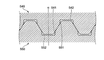
- FIG. 4 is a cross-sectional view taken along line IV-IV in FIG. 3 and shows a state in which a drive piece is opened.
- FIG. 4 is a cross-sectional view taken along the line IV-IV in FIG. 3 and shows a state in which a driving piece is closed. It is the perspective view which expanded the part of the drive piece of the 1st drive part in the binding unit of this embodiment, and the drive piece of the 2nd drive part.
- FIG. 6 is an enlarged view of a VI-VI cross section of the drive piece shown in FIG.
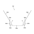
- FIG. 6 is an enlarged view of the VI-VI cross section of the drive piece shown in FIG. 5, showing a state in which the drive piece is brought close and the upper teeth and lower teeth are meshed without sandwiching the sheet bundle. It is an enlarged view of the recessed part of the lower tooth shown to FIG. 6A.
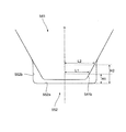
- FIG. 6B is an enlarged view of upper teeth and lower teeth shown in FIG. 6B. It is a figure which compares the binding process by the tooth mold in which the recessed area is formed in the recessed part and the binding process by the tooth mold in which the recessed area is not formed in the recessed part, and the upper teeth and the lower of the embodiment in which the recessed area is formed in the recessed part.
- FIG. 6 is a diagram illustrating a state in which pressure is applied with a sheet bundle interposed therebetween. It is a figure which shows the modification of the upper tooth and lower tooth in the binding unit of this embodiment, and is a figure which shows the state which the drive piece in the binding unit opened.
- FIG. 1 is a diagram showing a configuration of a recording material processing system 500 to which the present embodiment is applied.
- the recording material processing system 500 that functions as an example of an image processing apparatus includes an image forming apparatus 1 that forms an image on a recording material (sheet) such as paper P in an image forming unit using an electrophotographic method, and the like.
- a post-processing device 2 that performs post-processing on a plurality of sheets P on which images are formed by the image forming apparatus 1 is provided.
- the image forming apparatus 1 includes four image forming units 100Y, 100M, 100C, and 100K (also collectively referred to as “image forming unit 100”) that perform image formation based on each color image data. Further, the image forming apparatus 1 is provided with a laser exposure device 101 that exposes the photosensitive drums 107 provided in the respective image forming units 100 and forms an electrostatic latent image on the surface of the photosensitive drum 107.
- the image forming apparatus 1 also includes an intermediate transfer belt 102 on which toner images of the respective colors formed by the image forming units 100 are multiplex-transferred, and intermediate portions of the color toner images formed by the image forming units 100.
- a primary transfer roll 103 that sequentially transfers (primary transfer) to the transfer belt 102 is provided.
- the image forming apparatus 1 includes a secondary transfer roll 104 that collectively transfers (secondary transfer) each color toner image transferred onto the intermediate transfer belt 102 to the paper P, and each color toner image that has been secondarily transferred to the paper P.
- a fixing device 105 for fixing on top and a main body control unit 106 for controlling the operation of the image forming apparatus 1 are provided.
- each image forming unit 100 charging of the photosensitive drum 107 and formation of an electrostatic latent image on the photosensitive drum 107 are performed. Then, by developing the electrostatic latent image, a toner image of each color is formed on the surface of the photosensitive drum 107. Each color toner image formed on the surface of the photosensitive drum 107 is sequentially transferred onto the intermediate transfer belt 102 by the primary transfer roll 103. Each color toner image is conveyed to a position where the secondary transfer roll 104 is installed as the intermediate transfer belt 102 moves.
- the paper storage units 110A to 110D of the image forming apparatus 1 store different sizes and types of paper P. Then, for example, the paper P is taken out from the paper storage unit 110 ⁇ / b> A by the pickup roll 111 and conveyed to the registration roll 113 by the conveyance roll 112. Then, in accordance with the timing at which each color toner image on the intermediate transfer belt 102 is conveyed to the secondary transfer roll 104, the opposite transfer portion (secondary transfer portion) where the secondary transfer roll 104 and the intermediate transfer belt 102 face each other. Thus, the paper P is supplied from the registration roll 113. Each color toner image on the intermediate transfer belt 102 is collectively electrostatically transferred (secondary transfer) onto the paper P by the action of the transfer electric field formed by the secondary transfer roll 104.
- the paper P on which the color toner images are transferred is peeled off from the intermediate transfer belt 102 and conveyed to the fixing device 105.
- each color toner image is fixed on the paper P by a fixing process using heat and pressure, and an image is formed on the paper P.
- the paper P on which the image is formed is discharged from the paper discharge unit T of the image forming apparatus 1 by the transport roll 114 and is supplied to the post-processing apparatus 2 connected to the image forming apparatus 1.
- the post-processing device 2 is disposed on the downstream side of the paper discharge unit T of the image forming apparatus 1 and performs post-processing such as punching and binding on the paper P on which the image is formed.
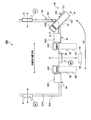
- FIG. 2 is a diagram for explaining the configuration of the post-processing device 2.
- the post-processing device 2 is predetermined for the transport unit 21 connected to the paper discharge unit T of the image forming apparatus 1 and the paper P conveyed by the transport unit 21.
- a finisher unit 22 for performing the above-described processing is provided.
- the post-processing device 2 includes a paper processing control unit 23 that controls each mechanism unit of the post-processing device 2.
- the paper processing control unit 23 is connected to the main body control unit 106 (see FIG. 1) via a signal line (not shown), and transmits and receives control signals and the like.
- the post-processing device 2 includes a stacker unit 80 on which the paper P (paper bundle B) that has been processed by the post-processing device 2 is stacked.
- the transport unit 21 of the post-processing apparatus 2 is provided with a punch function unit 30 that punches (punches) 2 holes or 4 holes. Further, the transport unit 21 is provided with a plurality of transport rolls 211 that transport the paper P after the image is formed by the image forming apparatus 1 toward the finisher unit 22.
- the finisher unit 22 is provided with a binding processing device 600 that performs a binding process on a sheet bundle B as an example of a recording material bundle.
- the binding processing apparatus 600 functions as an example of a binding unit, and performs a binding process on the sheet bundle B without using staples (needles).
- the binding processing device 600 is provided with a paper stacking unit 60 that supports the paper P from below and stacks a required number of sheets P to generate a paper bundle B. Further, the binding processing apparatus 600 is provided with a binding unit 50 that performs a binding process on the sheet bundle B.
- the sheet stacking unit 60 functions as an example of a holding unit that holds the sheet bundle B that is a recording material bundle.
- the advancing members (described later) provided in the binding unit 50 are pressed against the sheet bundle B from both sides of the sheet bundle B, thereby causing the sheets P constituting the sheet bundle B to be pressure-bonded to each other (the sheet P is The binding fibers are entangled with each other to perform binding processing on the sheet bundle B.
- the binding processing device 600 is provided with an unloading roll 61 and a moving roll 62.
- the carry-out roll 61 rotates in the clockwise direction in the drawing and sends the sheet bundle B on the sheet stacking unit 60 to the stacker unit 80.
- the moving roll 62 is provided so as to be movable around the rotation shaft 62 a, and is located at a position retracted from the carry-out roll 61 when the sheets P are stacked on the sheet stacking unit 60.
- the generated sheet bundle B is sent to the stacker unit 80, it is pressed against the sheet bundle B on the sheet stacking unit 60.
- the main body control unit 106 outputs an instruction signal for executing processing for the paper P to the paper processing control unit 23.
- the post-processing device 2 executes processing for the sheet P.
- the paper P on which image formation has been performed by the image forming apparatus 1 is supplied to the transport unit 21 of the post-processing apparatus 2.
- punching by the punch function unit 30 is performed in response to an instruction signal from the paper processing control unit 23, and then the paper P is transported toward the finisher unit 22 by the transport roll 211.
- the paper P is sent to the finisher unit 22 without being punched by the punch function unit 30.
- the paper P sent to the finisher unit 22 is conveyed to the paper stacking unit 60 provided in the binding processing device 600. Then, the paper P slides on the paper stacking unit 60 according to the inclination angle given to the paper stacking unit 60 and hits the paper regulating unit 64 provided at the end of the paper stacking unit 60.
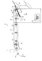
- FIG. 3 is a view of the binding processing device 600 as viewed from above.
- First moving members 81 are provided at both ends in the width direction of the paper stacking unit 60.
- the first moving member 81 is pressed against the side of the paper P constituting the paper bundle B, and aligns the positions of the end portions of the paper P constituting the paper bundle B.
- the first moving member 81 moves in the width direction of the sheet bundle B and moves the sheet bundle B in the width direction of the sheet bundle B.
- the first moving member 81 when the paper P is stacked on the paper stacking unit 60, the first moving member 81 is pressed against the side of the paper P so that the positions of the side of the paper P are aligned. As will be described later, when the binding position of the sheet bundle B is changed, the sheet bundle B is pressed by the first moving member 81, and the sheet bundle B moves in the width direction of the sheet bundle B.
- the second moving member 82 is provided in the binding processing apparatus 600 of the present embodiment.
- the second moving member 82 moves in the vertical direction in the drawing, and moves the sheet bundle B in a direction orthogonal to the width direction of the sheet bundle B.
- a moving motor M1 for moving the first moving member 81 and the second moving member 82 is provided.
- the binding unit 50 is provided to be movable in the width direction of the paper P.
- the binding unit 50 performs, for example, binding processing (two-point binding processing) on two points ((A) position and (B) position) located at different locations in the width direction of the sheet bundle B. Further, the binding unit 50 moves to the position (C) in FIG. 3 and performs a binding process (one-point binding) on the corner portion of the sheet bundle B.
- the binding unit 50 moves linearly between the position (A) and the position (B), but the binding unit 50 is, for example, 45 ° between the position (A) and the position (C). Move with rotation.
- the paper restricting portion 64 is formed in a C shape with a corner.
- a restricting portion (not shown) extending upward from the bottom plate 60A is provided inside the corner C-shape of the sheet restricting portion 64, and at the leading end portion of the sheet P conveyed by the restricting portion. The movement of the paper P is controlled by contact.
- the sheet restricting portion 64 has a facing portion 60C that is disposed facing the bottom plate 60A. The facing portion 60C comes into contact with the uppermost sheet P of the sheet bundle B and restricts the movement of the sheet P in the thickness direction of the sheet bundle B.
- the binding process by the binding unit 50 is performed at a location where the paper regulation unit 64 and the second moving member 82 are not provided. Specifically, as shown in FIG. 3, between the sheet restricting portion 64 and the second moving member 82 located on the left side in the drawing and between the sheet restricting portion 64 and the second moving member 82 located on the right side in the drawing. , The binding process by the binding unit 50 is performed. Further, in the present embodiment, the binding process is performed at a location (corner portion of the sheet bundle B) adjacent to the sheet regulating section 64 on the right side in the drawing.
- the bottom plate 60A is provided with three notches 60D. Thereby, interference between the paper stacking unit 60 and the binding unit 50 can be avoided.
- the second moving member 82 moves to a position indicated by reference numeral 4B in FIG. Thereby, interference with the binding unit 50 and the 2nd moving member 82 is avoided.
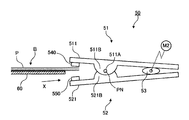
- the binding unit 50 includes a first drive unit 51 that extends in the left-right direction in the drawing, a second drive unit 52 that also extends in the left-right direction in the drawing, and a first drive unit 51 and a second drive unit 52.
- An elliptical cam 53 disposed between them and a cam motor M2 for driving the cam 53 are provided.
- the first driving unit 51 is provided with a driving piece 511.
- the drive piece 511 is formed in a plate shape, has one end on the sheet bundle B side, and has the other end on the side opposite to the one end.
- upper teeth 540 are attached to this one end of the drive piece 511.
- the upper teeth 540 advance toward the sheet bundle B from one side of the sheet bundle B and press the sheet bundle B.
- the driving piece 511 is provided with a protruding portion 511B that protrudes toward the second driving portion 52, and a through hole 511A is formed in the protruding portion 511B.
- the second drive unit 52 includes a drive piece 521.
- the driving piece 521 is formed in a plate shape, has one end on the sheet bundle B side, and has the other end on the side opposite to the one end.
- lower teeth 550 are attached to one end of the drive piece 521.
- the lower teeth 550 advance toward the other surface of the sheet bundle B and press the sheet bundle B.
- the drive piece 521 is provided with a protrusion 521B that protrudes toward the first drive unit 51, and the protrusion 521B has a through hole (positioned on the back surface of the through hole 511A of the first drive unit 51, (Not shown) is formed.
- the pin PN is passed through the through hole 511 ⁇ / b> A provided in the first drive unit 51 and the through hole (not shown) provided in the second drive unit 52.
- the drive piece 511 and the drive piece 521 swing around the pin PN.
- the upper teeth 540 and the lower teeth 550 are provided on the side of the sheet bundle B from the pin PN, and the cam 53 is provided on the side opposite to the side on which the sheet bundle B is provided across the pin PN. It has been.
- the structure having the upper teeth 540 and the lower teeth 550 functions as an example of a binding member. It is also possible to grasp the binding unit 50 shown in FIGS. 4A and 4B as an example of a binding member.
- the specific configuration of the binding unit 50 is not limited to the configuration described with reference to FIGS. 4A and 4B.
- Various types that can press the sheet bundle B with the upper teeth 540 and the lower teeth 550 can be employed.
- FIG. 5 is an enlarged perspective view of the drive piece 511 of the first drive unit 51 and the drive piece 521 of the second drive unit 52 in the binding unit 50 of the present embodiment.
- the driving piece 511 is provided with upper teeth 540
- the driving piece 521 is provided with lower teeth 550.
- the upper teeth 540 are provided at positions corresponding to the lower teeth 550 on the side facing the second drive unit 52 of the drive piece 511.
- the lower teeth 550 are provided at positions corresponding to the upper teeth 540 on the side facing the first drive unit 51 of the drive piece 521.
- the upper teeth 540 and the lower teeth 550 are formed by alternately arranging ridge-shaped convex portions 541 and 551 and groove-shaped concave portions 542 and 552, and the convex portions 541 and 551 as a whole. And it forms in the strip
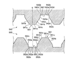
- 6A and 6B are enlarged views of the VI-VI cross section of the drive pieces 511 and 521 shown in FIG.
- An example of the shape of the teeth (upper teeth 540 and lower teeth 550) provided in the binding unit 50 in the binding processing device 600 will be described with reference to FIGS. 6A and 6B.
- 6A is a view showing a state where the drive pieces 511 and 521 are opened.
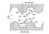
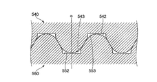
- FIG. 6B is a view showing the state where the drive pieces 511 and 521 are brought close to each other, and the upper teeth 540 and lower teeth 550 are placed without sandwiching the sheet bundle B. It is a figure which shows the state which meshed
- the convex portion 541 has a trapezoidal cross-sectional shape with rounded corners. That is, the convex portion 541 is formed by a flat top surface 541a, a side surface 541b that is a slope, and a convex curved surface 541c that connects the top surface 541a and the side surface 541b.
- the convex portion 541 has a line-symmetric shape with respect to a straight line ⁇ that equally divides the top surface 541a (that is, a virtual line ⁇ passing through the center of the convex portion 541).
- the side surface 541b is a plane.
- the convex part 551 of the lower tooth 550 is formed similarly. That is, the convex portion 551 is formed by the top surface 551a, the side surface 551b, and the convex curved surface 551c.
- the concave portion 552 includes a flat bottom surface 552a, first side surfaces 552b and second side surfaces 552c which are side walls, a concave curved surface 552d connecting the bottom surface 552a and the first side surface 552b, a first side surface 552b, and It is formed with a convex curved surface 552e that connects the second side surfaces 552c.
- the recess 552 has a shape symmetrical with respect to a straight line ⁇ that equally divides the bottom surface 552a.
- ⁇ that equally divides the bottom surface 552a.
- the second side surface 552c is a plane inclined at an angle equal to the side surface 541b of the convex portion 541.
- the first side surface 552b is a plane that forms an angle deeper than the second side surface 552c (the angle with respect to the bottom surface 552a is larger than the angle formed between the second side surface 552c and the bottom surface 552a).
- the recessed part 542 of the upper tooth 540 is formed similarly. That is, the concave portion 542 is formed of a bottom surface 542a, a first side surface 542b, a second side surface 542c, a concave curved surface 542d, and a convex curved surface 542e.
- the side surface 551b that is the slope of the convex portion 551 is the second side surface 552c of the concave portion 552 adjacent to the convex portion 551.
- the concave portions 542 and 552 are provided with first side surfaces 542b and 552b and convex curved surfaces 542e and 552e. For this reason, as shown in FIG. 6B, in the state where the upper teeth 540 and the lower teeth 550 are engaged with each other, gaps are generated in the vicinity of the top surfaces 551a and 541a of the convex portions 551 and 541.
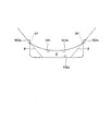
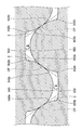
- FIG. 7 is an enlarged view of the recess 552 of the lower tooth 550 shown in FIG. 6A.
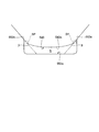
- FIG. 8 is an enlarged view of the upper teeth 540 and the lower teeth 550 shown in FIG. 6B.
- the gaps between the convex portions 541 and 551 and the concave portions 552 and 542 shown in FIG. 6B will be described in more detail.
- a first side surface 552 b and a convex curved surface 552 e are provided in the concave portion 552 of the lower tooth 550.
- recessed regions S that are recessed from an imaginary line ⁇ extending from the second side surface 552c are formed on both sides of the bottom surface 552a.
- the hollow region S is formed as a wider region than the virtual region formed by the virtual line ⁇ .
- FIG. 7 shows only the recess 552 of the lower tooth 550, the same applies to the recess 542 of the upper tooth 540. That is, a recessed region that is recessed from an imaginary line extending from the second side surface 542c is formed on both sides of the bottom surface 542a.
- FIG. 8 shows only the combination of the convex portion 541 of the upper tooth 540 and the concave portion 552 of the lower tooth 550, but also in the combination of the convex portion 551 of the lower tooth 550 and the concave portion 542 of the upper tooth 540. It is the same. That is, a space surrounded by the first side surface 542b and the bottom surface 542a of the concave portion 542 and the side surface 551b of the convex portion 551 is formed.
- the gap generated when the upper teeth 540 and the lower teeth 550 are engaged with each other will be further described.
- the gap is formed by the side surfaces 541b and 551b of the convex portions 541 and 551 and the recessed region S formed in the concave portions 552 and 542.
- convex curved surfaces 552e and 542e are provided in the concave portions 552 and 542, and the first side surfaces 552b and 542b and the second side surfaces having the side surfaces of the concave portions 552 and 542 as the first surface. It is formed by dividing into second side surfaces 552c and 542c.
- the concave curved surfaces 552d and 542d that are the first curved surfaces are concave surfaces
- the convex curved surfaces 552e and 542e that are the second curved surfaces are convex surfaces. That is, the centers of curvature of the concave curved surfaces 552d and 542d and the centers of curvature of the convex curved surfaces 552e and 542e exist on the opposite side with respect to the surfaces of the concave portions 552 and 542.
- a concave curved surface that is a concave surface for forming the groove shape of the concave portions 552, 542 on the side surfaces (first side surfaces 552b, 542b, second side surfaces 552c, 542c) of the concave portions 552, 542. Since the convex surfaces 552e and 542e having the center of curvature are provided on the opposite side of the center of curvature of 552d and 542d, a depression region S is formed, and a gap is formed when the upper teeth 540 and the lower teeth 550 are engaged with each other. Occurs.
- the bottom surfaces 552a and 542a of the concave portions 552 and 542 and the convex portions 541 and 551 are formed in the gap generated when the upper teeth 540 and the lower teeth 550 are engaged with each other.
- the following relationship is established between the side surfaces 541b and 551b. That is, as shown in FIG. 8, in the convex portions 541 and 551, the distance from the straight line ⁇ to the surfaces of the side surfaces 541b and 551b is a distance in the direction orthogonal to the straight line ⁇ that equally divides the top surfaces 541a and 551a.
- the positions on the side surfaces 541b and 551b, which are L1, are specified, and the distance between the position and the bottom surfaces 552a and 542a of the recesses 552 and 542 is a distance H1. Further, a position on the side surface 541b, 551b where the distance from the straight line ⁇ to the surface of the side surface 541b, 551b is the distance L2 is specified, and the separation distance between this position and the bottom surface 552a, 542a of the recess 552, 542 is the distance.
- H2 Let H2.
- L1 ⁇ L2 there is always a combination of L1 and L2 such that H1 ⁇ H2. Note that H1 ⁇ H2 is not always satisfied in all L1 and L2 such that L1 ⁇ L2.
- the upper teeth 540 and the lower teeth 550 are formed on a part of the side surfaces (first side surfaces 552b, 542b, second side surfaces 552c, 542c) of the concave portions 552, 542 as compared with the side surfaces 541b, 551b of the convex portions 541, 551.
- the first side surfaces 552b and 542b are provided as surfaces extending in a direction orthogonal to the moving direction (the pressing direction with respect to the sheet bundle B).
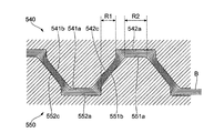
- FIGS. 6A, 6B and 7 are diagrams comparing a binding process using a tooth mold in which a recessed area S is formed in a recess and a binding process using a tooth mold in which the recessed area S is not formed in a recess.
- FIG. 9A is a diagram showing a state in which a pressure is applied with the sheet bundle B sandwiched between the upper teeth 540 and the lower teeth 550 of the present embodiment in which the depression region S is formed in the recess
- FIG. 9B is a comparison object.
- FIG. 10 is a view showing a state in which a pressure is applied with a sheet bundle B sandwiched between upper teeth 560 and lower teeth 570 in which a recessed region S is not formed in a recess.
- the upper teeth 560 and the lower teeth 570 are brought close to each other to apply pressure to the sheet bundle B, whereby the sheet bundle B is deformed along the shapes of the convex portions 561 and 571, and the sheet P is changed. It stretches and the fiber of the paper P breaks. The fibers of the broken sheets P are entangled between the overlapping sheets P, and the sheets P are bound to each other.
- one of the portions that apply pressure to the sheet bundle B is such that the side surfaces 541b of the convex portions 541 and 551 of the upper teeth 540 and the lower teeth 550 overlap the second side surfaces 552c and 542c of the concave portions 552 and 542.
- the range is R1.
- the other part of the portion that applies pressure to the sheet bundle B is a range R2 in which the top surfaces 541a and 551a of the convex portions 541 and 551 overlap with the bottom surfaces 552a and 542a of the concave portions 552 and 542.
- one of the portions that apply pressure to the sheet bundle B is the side surfaces 561b and 571b of the convex portions 561 and 571 of the upper teeth 560 and the lower teeth 570 and the surfaces 572c and 562c of the concave portions 572 and 562. It is the range R3 where and overlap.
- the other part of the portion that applies pressure to the sheet bundle B is a range R4 in which the top surfaces 561a and 571a of the convex portions 561 and 571 overlap with the bottom surfaces 572a and 562a of the concave portions 572 and 562.
- FIG. 9A is compared with FIG. 9B.
- the area of the range R1 is as follows.
- FIG. 9B does not include the depression region S in the depressions 562 and 572. In this case, the area is smaller than the area R3.
- FIG. 9A since the depression area S exists in the recesses 542 and 552, the paper P can be bent and escape to the gap formed by the depression area S when it is pressurized and stretched.
- FIG. 9B since the recessed area S does not exist in the recesses 562 and 572, the sheet P cannot be bent and escape when it is extended by being pressurized. For this reason, even when the driving force of the binding unit 50 that brings the upper teeth 540 and 560 and the lower teeth 550 and 570 closer to each other is equal, in the configuration in FIG. The paper P is more easily stretched than the configuration of FIG. 9B without S, and the fibers of the paper P are easily broken and entangled. For this reason, in the sheet bundle B, the portion pressed in the range R1 in the configuration of FIG. 9A is bound with the same force with a stronger binding force than the portion pressed in the range R3 in the configuration of FIG. 9A. Become.
- the angle formed between the first side surfaces 542b and 552b and the bottom surfaces 542a and 552a is larger than the angle formed between the second side surfaces 542c and 552c and the bottom surfaces 542a and 552a.
- the angle formed by the first side surface 552b and the bottom surface 552a may be smaller than 90 °.
- each plane is a curved surface (the convex curved surfaces 541c and 551c of the convex portions 541 and 551, the concave curved surfaces 542d of the concave portions 542 and 552, 552d and convex curved surfaces 542e and 552e).
- the convex portions 541 and 551 and the concave portions 542 and 552 are not provided with corners but are connected by curved surfaces, so that when the pressure is applied to the sheet bundle B, the convex portions 541 and 551 and the concave portions 542 and 552 have corners.
- the sheet P of the sheet bundle B is prevented from being cut.
- both the upper teeth 540 and the lower teeth 550 are formed with the recessed regions S in the recesses 542 and 552.
- only one of the upper teeth 540 and the lower teeth 550 has a recess (You may make it form the hollow area
- the sheet bundle B can escape to the gap generated when the concave area where the depression area S is formed is engaged with the opposing convex section, the binding force of the sheet bundle B is increased.
- the sheet bundle B that is pressed between the upper teeth 540 and the lower teeth 550 can escape in the gap generated when the upper teeth 540 and the lower teeth 550 are engaged with each other. Since the sheets P of the sheet bundle B are easily stretched, the binding force (binding force) of the sheet bundle B is increased. Therefore, the upper teeth 540 and the lower teeth 550 in the binding unit 50 may have any shape that causes the above-described gap when engaged, and the specific shapes thereof are the shapes described with reference to FIGS. 6A to 9B. Is not limited. Below, the modification of the upper tooth 540 and the lower tooth 550 is demonstrated.
- FIG. 10A and 10B are views showing a modification of the upper teeth 540 and the lower teeth 550 in the binding unit 50 of the present embodiment.
- FIG. 10A is a diagram showing a state in which the drive pieces 511 and 521 in the binding unit 50 are opened
- FIG. 10B is a view in which the drive pieces 511 and 521 are approached and the upper teeth 540 and the lower teeth are not sandwiched with the sheet bundle B interposed therebetween. It is a figure which shows the state which mesh
- the cross-sectional shapes of the convex portions 541 and 551 are trapezoidal.
- the convex portions 543 and 553 are formed by convex curved surfaces 543a and 553a including the vertices of the convex portions 543 and 553 and side surfaces 543b and 553b which are inclined surfaces.
- the widths of the top top surfaces 541a and 551a of the projections 541 and 551 shown in FIG. 6A are 0, and the convex curved surfaces 541c and 551c on both sides of the top surfaces 541a and 551a are connected. Therefore, it can be grasped as a shape having convex curved surfaces 543a and 553a.
- the recesses 542 and 552 shown in FIG. 10A are the same as the recesses 542 and 552 shown in FIG. 6A, and are given the same reference numerals. That is, the recesses 542 and 552 are formed by bottom surfaces 542a and 552a, first side surfaces 542b and 552b, second side surfaces 542c and 552c, concave curved surfaces 542d and 552d, and convex curved surfaces 542e and 552e. Accordingly, the recessed area S is formed by the convex curved surfaces 542e and 552e and the first side surfaces 542b and 552b. Then, as shown in FIG.
- voids are generated in the vicinity of the convex curved surfaces 543a and 553a in the convex portions 543 and 553, with the concave region S in a state where the upper teeth 540 and the lower teeth 550 are engaged with each other.
- the relationship between the convex curved surfaces 543a and 553a of the convex portions 543 and 553 and the bottom surfaces 552a and 542a of the concave portions 552 and 542 is The relationship between L1 and L2 and H1 and H2 described with reference to FIG. 8 is established. That is, the position on the convex curved surfaces 543a and 553a whose distance from the straight line ⁇ to the surface of the convex curved surfaces 543a and 553a is the distance L1 in the direction orthogonal to the straight line ⁇ that equally divides the convex curved surfaces 543a and 553a is specified.
- the separation distance between this position and the bottom surfaces 552a and 542a of the recesses 552 and 542 is defined as a distance H1. Further, a position on the convex curved surfaces 543a and 553a whose distance from the straight line ⁇ to the surfaces of the convex curved surfaces 543a and 553a is the distance L2 is specified, and a separation distance between this position and the bottom surfaces 552a and 542a of the concave portions 552 and 542 Is the distance H2.
- L1 ⁇ L2 there is always a combination of L1 and L2 such that H1 ⁇ H2.
- the shape of the hollow region S in this modification will be described in more detail.
- a plurality of modes are conceivable regarding the shape of the recessed area S depending on the positions of the convex curved surfaces 542e and 552e forming the recessed area S.
- the positions of the convex curved surfaces 542e and 552e are the positions where the convex curved surfaces 543a and 553a of the convex portions 543 and 553 are formed, that is, the positions where the convex portions 543 and 553 are separated from the virtual line ⁇ extending the second side surfaces 542c and 552c.
- a plurality of different positions can be taken.
- each aspect will be described.
- FIG. 11 is a diagram showing one aspect of the shape of the hollow region S in the modification of the tooth shown in FIGS. 10A and 10B.
- the convex curved surface 552e is formed at a position corresponding to the position SP where the convex portion 543 is separated from the virtual line ⁇ extending the second side surface 552c on the concave portion 552. That is, the position SP matches the position of the convex curved surface 552e.
- the shape of the depression region S formed between the opposing lower tooth recess 552 and the upper tooth protrusion 543 has been described. However, the upper tooth recess 542 and the lower tooth protrusion facing each other. The same applies to the shape of the recessed region S formed between 553.
- FIG. 12 is a diagram illustrating another aspect of the shape of the recessed region S in the modification of the tooth illustrated in FIGS. 10A and 10B.
- a convex curved surface 552e is formed on the concave portion 552 at a position where a virtual line ⁇ extending the second side surface 552c and the convex portion 543 overlap. Accordingly, the position SP at which the convex portion 543 is separated from the virtual line ⁇ is located on the tip side of the position corresponding to the convex curved surface 552e on the convex portion 543.
- the shape of the depression region S formed between the opposing lower tooth recess 552 and the upper tooth protrusion 543 has been described. However, the upper tooth recess 542 and the lower tooth protrusion facing each other. The same applies to the shape of the recessed region S formed between 553.
- FIG. 13 is a diagram illustrating another aspect of the shape of the recessed region S in the modification of the tooth illustrated in FIGS. 10A and 10B.
- the convex curved surface 552e is formed at a position closer to the intersection I of the virtual line ⁇ than the position SP where the convex part 543 moves away from the virtual line ⁇ extending the second side surface 552c on the concave portion 552. Yes. Therefore, the position SP is at a position where the convex portion 543 is in contact with the second side surface 552c of the concave portion 552 facing the convex portion 543.
- the shape of the depression region S formed between the opposing lower tooth recess 552 and the upper tooth protrusion 543 has been described.
- the upper tooth recess 542 and the lower tooth protrusion facing each other The same applies to the shape of the recessed region S formed between 553.
- FIG. 14 is a diagram showing another aspect of the shape of the recessed region S in the modification example of the tooth shown in FIGS. 10A and 10B.
- the side surfaces 543b and 553b in the convex portions 543 and 553 and the first side surfaces 542b and 552b in the adjacent concave portions 542 and 552 are smoothly connected.
- the second side surfaces 542c and 552c and the convex curved surfaces 542e and 552e which are flat surfaces, exist in the teeth shown in FIGS. 10A and 10B.
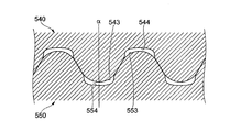
- FIGS. 15A and 15B are diagrams showing another modification of the upper teeth 540 and the lower teeth 550 in the binding unit 50 of the present embodiment.
- FIG. 15A is a diagram showing a state in which the drive pieces 511 and 521 in the binding unit 50 are opened.
- FIG. 15B) shows the state where the drive pieces 511 and 521 are brought close to each other and the upper teeth 540 are not sandwiched with the sheet bundle B interposed therebetween. It is a figure which shows the state which meshed the lower tooth 550.
- the bottom surfaces 542a and 552a having flat surfaces are provided in the recesses 542 and 552, respectively.
- the recesses 544 and 554 have concave curved surfaces 544a and 554a, first side surfaces 544b and 554b and second side surfaces 544c and 554c, which are side walls, It is formed with convex curved surfaces 544d and 554d connecting the side surfaces 544b and 554b and the second side surfaces 544c and 554c.
- the convex portions 543 and 553 shown in FIG. 15A are the same as the convex portions 543 and 553 shown in FIG. 10A, and are given the same reference numerals. That is, the convex portions 553 and 543 are formed by convex curved surfaces 543a and 553a and side surfaces 543b and 553b which are inclined surfaces. Therefore, in the state where the upper teeth 540 and the lower teeth 550 are engaged with each other, gaps are generated in the vicinity of the convex curved surfaces 543a and 553a in the convex portions 543 and 553 as shown in FIG. 15B.
- the curvature radii of the concave curved surfaces 554a and 544a of the concave portions 554 and 544 are set larger than the convex curved surfaces 543a and 553a of the convex portions 543 and 553. Therefore, regarding the above-mentioned gap, L1, L2, and H1 described with reference to FIG. 8 also in the relationship between the convex curved surfaces 543a and 553a of the convex portions 543 and 553 and the concave curved surfaces 554a and 544a of the concave portions 554 and 544, The relationship with H2 is established.
- the position on the convex curved surfaces 543a and 553a whose distance from the straight line ⁇ to the surface of the convex curved surfaces 543a and 553a is the distance L1 in the direction orthogonal to the straight line ⁇ that equally divides the convex curved surfaces 543a and 553a is specified.
- the distance between this position and the concave curved surfaces 554a and 544a of the concave portions 552 and 542 is defined as a distance H1.
- a position on the convex curved surfaces 543a and 553a whose distance from the straight line ⁇ to the surfaces of the convex curved surfaces 543a and 553a is the distance L2 is specified, and a separation distance between this position and the bottom surfaces 552a and 542a of the concave portions 552 and 542 Is the distance H2.
- L1 ⁇ L2 there is always a combination of L1 and L2 such that H1 ⁇ H2.
- each tooth type mentioned above provided the plane side surfaces 541b, 551b, 543b, and 553b in the convex parts 541, 551, 543, and 553, respectively.
- the concave portions 542, 552, 544, and 554 were provided with second planar side surfaces 542c, 552c, 544c, and 554c corresponding to the planar side surfaces 541b, 551b, 543b and 553b.
- a recessed region S that is recessed from the imaginary line ⁇ extending from the second side surfaces 542c, 552c, 544c, and 554c is formed.
- the side surfaces of the convex portion and the concave portion are not flat, it may be possible to form the recessed region S.
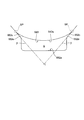
- FIG. 16 is a diagram illustrating an example of teeth in which the side surfaces of the convex portion and the concave portion are curved surfaces.
- the convex portions 545 and 555 of the upper teeth 540 and the lower teeth 550 shown in FIG. 16 are formed by convex curved surfaces 545a and 555a.
- the concave portions 546 and 556 are convex curved surfaces that connect the concave curved surfaces 546a and 556a, the first side surfaces 546b and 556b and the second side surfaces 546c and 556c, and the first side surfaces 546b and 556b and the second side surfaces 546c and 556c. 546d and 556d.
- a part of convex curved surface 545a, 555a becomes a side surface.
- the second side surfaces 546c and 556c of the concave portions 546 and 556 correspond to the side surface portions of the convex portions 555 and 545 facing each other. That is, the second side surfaces 546c and 556c are concave curved surfaces having the same curvature as the side surface portions of the convex portions 555 and 545.
- the convex portions 545 and 555 are formed only by the convex curved surfaces 545a and 555a. And if it becomes a concave curved surface beyond the inflection point IP, it will become the 2nd side surface 546c, 556c of the recessed part 546,556. In the recesses 546 and 556, the convex curved surfaces 546d and 556d further reach the first side surfaces 546b and 556b, and are connected to the concave curved surfaces 546a and 556a.
- the concave regions S are formed by providing the convex curved surfaces 546d and 556d and the first side surfaces 546b and 556b.
- the recessed area S is not a virtual line obtained by extending the second side surfaces 546c and 556c which are concave curved surfaces, but is second from the convex curved surfaces 545a and 555a of the adjacent convex portions 545 and 555 as shown in FIG. You may grasp
- FIG. 17 is a diagram illustrating a configuration example in which the first side surface 557b of the concave portion is a curved surface.
- FIG. 17 shows a lower tooth recess 557.
- the illustrated recess 557 is formed of a bottom surface 557a, first side surfaces 557b and second side surfaces 557c which are side walls, and a convex curved surface 557d which connects the first side surface 557b and the second side surface 557c.
- the first side surface 557b is a concave curved surface, and is smoothly connected to the bottom surface 557a.
- the first side surface 557b of the concave portion 557 can be grasped as a shape in which the first side surface 552b and the concave curved surface 552d shown in FIG. 7 are fused.
- the shapes of the upper teeth 540 and the lower teeth 550 have been described with a plurality of configurations.
- the pressed sheet bundle B is The shape is not limited to the above-described configuration examples as long as a gap that can be bent and escape is generated.
- Each configuration example may be combined and can be implemented in various forms without departing from the gist of the present disclosure.
Landscapes
- Engineering & Computer Science (AREA)
- Textile Engineering (AREA)
- Physics & Mathematics (AREA)
- General Physics & Mathematics (AREA)
- Folding Of Thin Sheet-Like Materials, Special Discharging Devices, And Others (AREA)
Abstract
綴じ部材は、用紙束に凹凸を形成するための凸部および凹部からなる歯型を有する上歯と、記録材束に凹凸を形成するための歯型であって上歯と対をなす凹部および凸部からなる下歯と、を有する。この綴じ部材の上歯および下歯の少なくとも何れか一方で、対峙する一方の歯の凹部の側面の一部に、他方の歯の凸部の斜面に比べて歯の押圧方向と直交する方向に広がる面である第1側面が形成されている。
Description
本発明は、綴じ部材、綴じ処理装置および画像処理装置に関する。
特許文献1には、凹凸が連なった形状に形成された一対の綴じ部材によって複数枚重ねた用紙を挟んだ状態で、綴じ部材に圧力をかけて噛み合わせることで、複数枚の用紙を綴じ込む綴じ部材が開示されている。
記録材束に対して凹凸を形成して綴じる綴じ処理においては、綴じた個所をより剥離し難くすることや、より多くの枚数の記録材束を綴じることが求められる場合がある。これを実現するために、綴じ処理により綴じられた箇所の結着力を高めることが求められる。
本発明の少なくとも一の実施形態は、凸部と凹部とを組み合わせて記録材束を綴じる綴じ処理に用いられる歯を特定の形状とすることにより記録材束の結着力を高めることを目的とする。
本発明の少なくとも一の実施形態は、凸部と凹部とを組み合わせて記録材束を綴じる綴じ処理に用いられる歯を特定の形状とすることにより記録材束の結着力を高めることを目的とする。
[1]本発明の少なくとも一の実施形態は、
記録材束に凹凸を形成するための歯型を有する上歯と、
記録材束に凹凸を形成するための歯型であって前記上歯と対をなす下歯と、
を備え、
前記上歯および前記下歯の少なくとも何れか一方で、
対峙する一方の歯の凹部の側面の一部に、他方の歯の凸部の斜面に比べて歯の押圧方向と直交する方向に広がる面が形成されている綴じ部材である。
[2]上記[1]の綴じ部材において、
前記凹部における前記歯の押圧方向と直交する方向に広がる面は、平面であってもよい。
[3]上記[1]の綴じ部材において、
前記凹部における前記歯の押圧方向と直交する方向に広がる面は、曲面であってもよい。
[4]上記[1]の綴じ部材において、
対峙する前記一方の歯の前記凹部と前記他方の歯の前記凸部とは、当該凹部の前記側面において前記歯の押圧方向と直交する方向に広がる面を除く部分と、当該凸部の斜面の一部とが対向してもよい。
[5]本発明の少なくとも一の実施形態は、
記録材束を保持する保持部と、
前記保持部に保持された記録材束に対して凹凸を形成して綴じ処理を施す、対となる上歯および下歯を有する綴じ部材と、を備え、
前記綴じ部材は、
前記上歯および前記下歯の少なくとも何れか一方において、対峙する一方の歯の凹部の側面の一部に、他方の歯の凸部の斜面に比べて歯の押圧方向と直交する方向に広がる面が形成されている綴じ処理装置である。
[6]本発明の少なくとも一の実施形態は、
記録材に画像を形成する画像形成部と、
前記画像形成部により画像が形成された記録材の束に対して凹凸を形成して綴じ処理を施す、対となる上歯および下歯を有する綴じ部と、を備え、
前記綴じ部は、
前記上歯および前記下歯の少なくとも何れか一方において、対峙する一方の歯の凹部の側面の一部に、他方の歯の凸部の斜面に比べて歯の押圧方向と直交する方向に広がる面が形成されている画像処理装置である。
記録材束に凹凸を形成するための歯型を有する上歯と、
記録材束に凹凸を形成するための歯型であって前記上歯と対をなす下歯と、
を備え、
前記上歯および前記下歯の少なくとも何れか一方で、
対峙する一方の歯の凹部の側面の一部に、他方の歯の凸部の斜面に比べて歯の押圧方向と直交する方向に広がる面が形成されている綴じ部材である。
[2]上記[1]の綴じ部材において、
前記凹部における前記歯の押圧方向と直交する方向に広がる面は、平面であってもよい。
[3]上記[1]の綴じ部材において、
前記凹部における前記歯の押圧方向と直交する方向に広がる面は、曲面であってもよい。
[4]上記[1]の綴じ部材において、
対峙する前記一方の歯の前記凹部と前記他方の歯の前記凸部とは、当該凹部の前記側面において前記歯の押圧方向と直交する方向に広がる面を除く部分と、当該凸部の斜面の一部とが対向してもよい。
[5]本発明の少なくとも一の実施形態は、
記録材束を保持する保持部と、
前記保持部に保持された記録材束に対して凹凸を形成して綴じ処理を施す、対となる上歯および下歯を有する綴じ部材と、を備え、
前記綴じ部材は、
前記上歯および前記下歯の少なくとも何れか一方において、対峙する一方の歯の凹部の側面の一部に、他方の歯の凸部の斜面に比べて歯の押圧方向と直交する方向に広がる面が形成されている綴じ処理装置である。
[6]本発明の少なくとも一の実施形態は、
記録材に画像を形成する画像形成部と、
前記画像形成部により画像が形成された記録材の束に対して凹凸を形成して綴じ処理を施す、対となる上歯および下歯を有する綴じ部と、を備え、
前記綴じ部は、
前記上歯および前記下歯の少なくとも何れか一方において、対峙する一方の歯の凹部の側面の一部に、他方の歯の凸部の斜面に比べて歯の押圧方向と直交する方向に広がる面が形成されている画像処理装置である。
[1]に記載の綴じ部材によれば、上歯と下歯とにより記録材束に圧力を加えた際に、凹部に形成された押圧方向と直交する方向に広がる斜面により形成される窪み領域に記録材束が逃げることができるため、加圧された記録材が伸びやすくなり、記録材束の結着力を高めることができる。
[2]に記載の綴じ部材によれば、上歯と下歯とにより記録材束に圧力を加えた際に、凹部に形成された押圧方向と直交する方向に広がる平面の斜面により形成される窪み領域に記録材束が逃げることができるため、加圧された記録材が伸びやすくなり、記録材束の結着力を高めることができる。
[3]に記載の綴じ部材によれば、上歯と下歯とにより記録材束に圧力を加えた際に、凹部に形成された押圧方向と直交する方向に広がる曲面の斜面により形成される窪み領域に記録材束が逃げることができるため、加圧された記録材が伸びやすくなり、記録材束の結着力を高めることができる。
[4]に記載の綴じ部材によれば、記録材束に圧力が加わる凸部および凹部の斜面の一部に、押圧方向と直交する方向に広がる斜面による窪み領域を形成することができるため、加圧された記録材を伸びやすくすることができる。
[5]に記載の綴じ処理装置によれば、上歯と下歯とにより記録材束に圧力を加えた際に、凹部に形成された押圧方向と直交する方向に広がる斜面により形成される窪み領域に記録材束が逃げることができるため、加圧された記録材が伸びやすく、記録材束の結着力を高めることができる。
[6]に記載の画像処理装置によれば、上歯と下歯とにより記録材束に圧力を加えた際に、凹部に形成された押圧方向と直交する方向に広がる斜面により形成される窪み領域に記録材束が逃げることができるため、加圧された記録材が伸びやすく、記録材束の結着力を高めることができる。
[2]に記載の綴じ部材によれば、上歯と下歯とにより記録材束に圧力を加えた際に、凹部に形成された押圧方向と直交する方向に広がる平面の斜面により形成される窪み領域に記録材束が逃げることができるため、加圧された記録材が伸びやすくなり、記録材束の結着力を高めることができる。
[3]に記載の綴じ部材によれば、上歯と下歯とにより記録材束に圧力を加えた際に、凹部に形成された押圧方向と直交する方向に広がる曲面の斜面により形成される窪み領域に記録材束が逃げることができるため、加圧された記録材が伸びやすくなり、記録材束の結着力を高めることができる。
[4]に記載の綴じ部材によれば、記録材束に圧力が加わる凸部および凹部の斜面の一部に、押圧方向と直交する方向に広がる斜面による窪み領域を形成することができるため、加圧された記録材を伸びやすくすることができる。
[5]に記載の綴じ処理装置によれば、上歯と下歯とにより記録材束に圧力を加えた際に、凹部に形成された押圧方向と直交する方向に広がる斜面により形成される窪み領域に記録材束が逃げることができるため、加圧された記録材が伸びやすく、記録材束の結着力を高めることができる。
[6]に記載の画像処理装置によれば、上歯と下歯とにより記録材束に圧力を加えた際に、凹部に形成された押圧方向と直交する方向に広がる斜面により形成される窪み領域に記録材束が逃げることができるため、加圧された記録材が伸びやすく、記録材束の結着力を高めることができる。
以下、添付図面を参照して、本発明の実施形態について詳細に説明する。
<記録材処理システムの構成>
図1は、本実施形態が適用される記録材処理システム500の構成を示した図である。
画像処理装置の一例として機能する記録材処理システム500には、画像形成部にて用紙Pなどの記録材(シート)に対して電子写真方式等を用いて画像を形成する画像形成装置1、および、画像形成装置1により画像が形成された複数枚の用紙Pに対して後処理を行う後処理装置2が設けられている。
<記録材処理システムの構成>
図1は、本実施形態が適用される記録材処理システム500の構成を示した図である。
画像処理装置の一例として機能する記録材処理システム500には、画像形成部にて用紙Pなどの記録材(シート)に対して電子写真方式等を用いて画像を形成する画像形成装置1、および、画像形成装置1により画像が形成された複数枚の用紙Pに対して後処理を行う後処理装置2が設けられている。
画像形成装置1は、各色画像データに基づいて画像形成を行う4つの画像形成ユニット100Y、100M、100C、100K(「画像形成ユニット100」とも総称する)を備える。また、画像形成装置1には、各画像形成ユニット100に設けられた感光体ドラム107を露光し、感光体ドラム107の表面に静電潜像を形成するレーザ露光装置101が設けられている。
また、画像形成装置1には、各画像形成ユニット100にて形成された各色のトナー像が多重転写される中間転写ベルト102、および、各画像形成ユニット100にて形成された各色トナー像を中間転写ベルト102に順次転写(一次転写)する一次転写ロール103が設けられている。さらに、画像形成装置1には、中間転写ベルト102上に転写された各色トナー像を用紙Pに一括転写(二次転写)する二次転写ロール104、二次転写された各色トナー像を用紙P上に定着する定着装置105、および、画像形成装置1の動作を制御する本体制御部106が設けられている。
各画像形成ユニット100では、感光体ドラム107の帯電、および、感光体ドラム107への静電潜像の形成が行われる。そして、静電潜像の現像が行われることにより、感光体ドラム107の表面には、各色のトナー像が形成される。
感光体ドラム107の表面に形成された各色トナー像は、一次転写ロール103により中間転写ベルト102上に順次転写される。そして、各色トナー像は、中間転写ベルト102の移動に伴って二次転写ロール104が設置された位置へ搬送される。
感光体ドラム107の表面に形成された各色トナー像は、一次転写ロール103により中間転写ベルト102上に順次転写される。そして、各色トナー像は、中間転写ベルト102の移動に伴って二次転写ロール104が設置された位置へ搬送される。
画像形成装置1の用紙収容部110A~110Dには、異なるサイズや異なる種類の用紙Pが収容されている。そして、例えば、ピックアップロール111により用紙収容部110Aから用紙Pが取り出され、搬送ロール112によってレジストロール113まで搬送される。
そして、中間転写ベルト102上の各色トナー像が二次転写ロール104に搬送されるタイミングに合わせて、二次転写ロール104と中間転写ベルト102とが対向する対向部(二次転写部)に対してレジストロール113から用紙Pが供給される。
そして、中間転写ベルト102上の各色トナー像が、二次転写ロール104により形成された転写電界の作用によって、用紙P上に一括して静電転写(二次転写)される。
そして、中間転写ベルト102上の各色トナー像が二次転写ロール104に搬送されるタイミングに合わせて、二次転写ロール104と中間転写ベルト102とが対向する対向部(二次転写部)に対してレジストロール113から用紙Pが供給される。
そして、中間転写ベルト102上の各色トナー像が、二次転写ロール104により形成された転写電界の作用によって、用紙P上に一括して静電転写(二次転写)される。
その後、各色トナー像が転写された用紙Pは、中間転写ベルト102から剥離されて定着装置105へ搬送される。定着装置105では、熱および圧力による定着処理により、各色トナー像が用紙P上に定着され、用紙P上に画像が形成される。
そして、画像が形成された用紙Pは、搬送ロール114によって画像形成装置1の用紙排出部Tから排出され、画像形成装置1に接続された後処理装置2へ供給される。
後処理装置2は、画像形成装置1の用紙排出部Tの下流側に配置され、画像が形成された用紙Pに対して穴あけや綴じ等の後処理を行う。
そして、画像が形成された用紙Pは、搬送ロール114によって画像形成装置1の用紙排出部Tから排出され、画像形成装置1に接続された後処理装置2へ供給される。
後処理装置2は、画像形成装置1の用紙排出部Tの下流側に配置され、画像が形成された用紙Pに対して穴あけや綴じ等の後処理を行う。
<後処理装置の構成>
図2は、後処理装置2の構成を説明するための図である。
図2に示すように、後処理装置2は、画像形成装置1の用紙排出部Tに接続されたトランスポートユニット21、および、トランスポートユニット21により搬送されてきた用紙Pに対して予め定められた処理を施すフィニッシャユニット22を備える。
図2は、後処理装置2の構成を説明するための図である。
図2に示すように、後処理装置2は、画像形成装置1の用紙排出部Tに接続されたトランスポートユニット21、および、トランスポートユニット21により搬送されてきた用紙Pに対して予め定められた処理を施すフィニッシャユニット22を備える。
また、後処理装置2は、後処理装置2の各機構部を制御する用紙処理制御部23を備える。用紙処理制御部23は、不図示の信号ラインで本体制御部106(図1参照)に接続され、相互に制御信号等の送受信を行う。
また、後処理装置2は、後処理装置2による処理が終了した用紙P(用紙束B)が積載されるスタッカー部80を備える。
また、後処理装置2は、後処理装置2による処理が終了した用紙P(用紙束B)が積載されるスタッカー部80を備える。
図2に示すように、後処理装置2のトランスポートユニット21には、2穴や4穴等の穴あけ(パンチ)を施すパンチ機能部30が設けられている。
さらに、トランスポートユニット21には、画像形成装置1にて画像形成された後の用紙Pをフィニッシャユニット22に向けて搬送する複数の搬送ロール211が設けられている。
さらに、トランスポートユニット21には、画像形成装置1にて画像形成された後の用紙Pをフィニッシャユニット22に向けて搬送する複数の搬送ロール211が設けられている。
フィニッシャユニット22には、記録材束の一例としての用紙束Bに対する綴じ処理を行う綴じ処理装置600が設けられている。本実施形態の綴じ処理装置600は、綴じ部の一例として機能し、ステープル(針)を用いずに用紙束Bに対する綴じ処理を行う。
綴じ処理装置600には、用紙Pを下方から支持するとともに用紙Pを必要枚数だけ集積させて用紙束Bを生成する用紙集積部60が設けられている。また、綴じ処理装置600には、用紙束Bに対して綴じ処理を行う綴じユニット50が設けられている。なお、用紙集積部60は、記録材束である用紙束Bを保持する保持部の一例として機能する。
本実施形態では、綴じユニット50に設けられた進出部材(後述)を用紙束Bの両面側から用紙束Bに押し当てることで、用紙束Bを構成する用紙Pを互いに圧着させ(用紙Pを構成する繊維同士を絡ませ)、用紙束Bに対する綴じ処理を行う。
本実施形態では、綴じユニット50に設けられた進出部材(後述)を用紙束Bの両面側から用紙束Bに押し当てることで、用紙束Bを構成する用紙Pを互いに圧着させ(用紙Pを構成する繊維同士を絡ませ)、用紙束Bに対する綴じ処理を行う。
また、綴じ処理装置600には、搬出ロール61および移動ロール62が設けられている。搬出ロール61は、図中時計回り方向に回転し、用紙集積部60上の用紙束Bをスタッカー部80へ送る。
移動ロール62は、回転軸62aを中心に移動可能に設けられ、用紙Pを用紙集積部60に集積させる際には搬出ロール61から退避した箇所に位置する。また、生成された用紙束Bをスタッカー部80へ送る際には、用紙集積部60上の用紙束Bに押し当てられる。
移動ロール62は、回転軸62aを中心に移動可能に設けられ、用紙Pを用紙集積部60に集積させる際には搬出ロール61から退避した箇所に位置する。また、生成された用紙束Bをスタッカー部80へ送る際には、用紙集積部60上の用紙束Bに押し当てられる。
後処理装置2にて行われる処理について説明する。
本実施形態では、本体制御部106から用紙処理制御部23に対し、用紙Pに対する処理を実行する旨の指示信号が出力される。用紙処理制御部23がこの指示信号を受信することで、後処理装置2が用紙Pに対する処理を実行する。
本実施形態では、本体制御部106から用紙処理制御部23に対し、用紙Pに対する処理を実行する旨の指示信号が出力される。用紙処理制御部23がこの指示信号を受信することで、後処理装置2が用紙Pに対する処理を実行する。
後処理装置2での処理では、まず、後処理装置2のトランスポートユニット21に対し、画像形成装置1により画像形成が行われた用紙Pが供給される。トランスポートユニット21では、用紙処理制御部23からの指示信号に応じてパンチ機能部30による穴あけが行われた後、搬送ロール211によって、フィニッシャユニット22に向けて用紙Pが搬送される。
なお、用紙処理制御部23からの穴あけ指示が無い場合、用紙Pは、パンチ機能部30による穴あけ処理は行われずにフィニッシャユニット22へ送られる。
なお、用紙処理制御部23からの穴あけ指示が無い場合、用紙Pは、パンチ機能部30による穴あけ処理は行われずにフィニッシャユニット22へ送られる。
フィニッシャユニット22に送られた用紙Pは、綴じ処理装置600に設けられた用紙集積部60へ搬送される。そして、用紙Pは、用紙集積部60に付与された傾斜角によって用紙集積部60の上をスライド移動し、用紙集積部60の端部に設けられた用紙規制部64に突き当たる。
これにより用紙Pは移動を停止する。本実施形態では、用紙規制部64に用紙Pが突き当たることで、用紙Pの後端部が揃えられた状態の用紙束Bが用紙集積部60上に生成される。なお、本実施形態では、用紙Pを用紙規制部64に向けて移動させる回転パドル63が設けられている。
<綴じ処理装置の構成>
図3は、綴じ処理装置600を上方から見た図である。
用紙集積部60の幅方向における両端部には、第1移動部材81が設けられている。
第1移動部材81は、用紙束Bを構成する用紙Pの側辺に押し当てられ、用紙束Bを構成する用紙Pの端部の位置を揃える。また、第1移動部材81は、用紙束Bの幅方向に移動し、用紙束Bの幅方向へ用紙束Bを移動させる。
図3は、綴じ処理装置600を上方から見た図である。
用紙集積部60の幅方向における両端部には、第1移動部材81が設けられている。
第1移動部材81は、用紙束Bを構成する用紙Pの側辺に押し当てられ、用紙束Bを構成する用紙Pの端部の位置を揃える。また、第1移動部材81は、用紙束Bの幅方向に移動し、用紙束Bの幅方向へ用紙束Bを移動させる。
具体的には、本実施形態では、用紙Pが用紙集積部60に集積される際、用紙Pの側辺に第1移動部材81が押し当てられ、用紙Pの側辺の位置が揃えられる。
また、後述するように、用紙束Bの綴じ位置が変更される場合には、第1移動部材81によって用紙束Bが押圧され、用紙束Bの幅方向に用紙束Bが移動する。
また、後述するように、用紙束Bの綴じ位置が変更される場合には、第1移動部材81によって用紙束Bが押圧され、用紙束Bの幅方向に用紙束Bが移動する。
さらに、本実施形態の綴じ処理装置600には、第2移動部材82が設けられている。
第2移動部材82は、図中上下方向に移動し、用紙束Bの幅方向と直交する方向に用紙束Bを移動させる。
さらに、本実施形態では、第1移動部材81、第2移動部材82を移動させる移動用モータM1が設けられている。
第2移動部材82は、図中上下方向に移動し、用紙束Bの幅方向と直交する方向に用紙束Bを移動させる。
さらに、本実施形態では、第1移動部材81、第2移動部材82を移動させる移動用モータM1が設けられている。
図3の矢印4Aで示すように、綴じユニット50は、用紙Pの幅方向に移動可能に設けられている。そして、綴じユニット50は、例えば、用紙束Bの幅方向において異なる箇所に位置する2点((A)位置と(B)位置)に対して、綴じ処理(2点綴じ処理)を行う。
また、綴じユニット50は、図3の(C)位置へ移動し、用紙束Bの角部に対して綴じ処理(1点綴じ)を行う。
なお、(A)位置と(B)位置との間では、綴じユニット50は直線的に移動するが、(A)位置と(C)位置との間では、綴じユニット50は、例えば45°の回転を伴いながら移動する。
また、綴じユニット50は、図3の(C)位置へ移動し、用紙束Bの角部に対して綴じ処理(1点綴じ)を行う。
なお、(A)位置と(B)位置との間では、綴じユニット50は直線的に移動するが、(A)位置と(C)位置との間では、綴じユニット50は、例えば45°の回転を伴いながら移動する。
用紙規制部64は、角のあるC字状に形成される。この用紙規制部64の角のあるC字状の内側にて、底板60Aから上方に伸びる規制部(図示せず)が設けられ、この規制部にて、搬送されてきた用紙Pの先端部に接触し用紙Pの移動を規制する。また、用紙規制部64は、底板60Aに対向配置される対向部60Cを有している。この対向部60Cは、用紙束Bのうちの最上位の用紙Pに接触して、用紙束Bの厚み方向における用紙Pの移動を規制する。
本実施形態では、用紙規制部64、第2移動部材82が設けられていない箇所にて、綴じユニット50による綴じ処理が行われる。
具体的には、図3に示すように、図中左側に位置する用紙規制部64と第2移動部材82との間、および、図中右側に位置する用紙規制部64と第2移動部材82との間にて、綴じユニット50による綴じ処理が行われる。さらに、本実施形態では、図中右側の用紙規制部64に隣接する箇所(用紙束Bの角部)にて綴じ処理が行われる。
具体的には、図3に示すように、図中左側に位置する用紙規制部64と第2移動部材82との間、および、図中右側に位置する用紙規制部64と第2移動部材82との間にて、綴じユニット50による綴じ処理が行われる。さらに、本実施形態では、図中右側の用紙規制部64に隣接する箇所(用紙束Bの角部)にて綴じ処理が行われる。
なお、図3に示すように、底板60Aには、3つの切り欠き60Dが設けられている。これにより、用紙集積部60と綴じユニット50との干渉が避けられる。
また、本実施形態では、綴じユニット50が移動する際、第2移動部材82は、図3の符号4Bで示す位置へ移動する。これにより、綴じユニット50と第2移動部材82との干渉が避けられる。
また、本実施形態では、綴じユニット50が移動する際、第2移動部材82は、図3の符号4Bで示す位置へ移動する。これにより、綴じユニット50と第2移動部材82との干渉が避けられる。
図4A、4Bは、図3のIV-IV線における断面図である。
図4Aに示すように、綴じユニット50は、図中左右方向に伸びる第1駆動部51、同じく図中左右方向に伸びる第2駆動部52、第1駆動部51と第2駆動部52との間に配置された楕円状のカム53、カム53を駆動するカムモータM2を備える。
図4Aに示すように、綴じユニット50は、図中左右方向に伸びる第1駆動部51、同じく図中左右方向に伸びる第2駆動部52、第1駆動部51と第2駆動部52との間に配置された楕円状のカム53、カム53を駆動するカムモータM2を備える。
第1駆動部51には、駆動片511が設けられている。駆動片511は、板状に形成され、用紙束B側に一端部を有し、一端部とは反対側に他端部を有する。
本実施形態では、駆動片511のこの一端部に、上歯540が取り付けられている。上歯540は、用紙束Bの一方の面側から用紙束Bに向かって進出してこの用紙束Bを押圧する。また、駆動片511には、第2駆動部52側に向かって突出する突出部511Bが設けられ、さらに、この突出部511Bには、貫通孔511Aが形成されている。
本実施形態では、駆動片511のこの一端部に、上歯540が取り付けられている。上歯540は、用紙束Bの一方の面側から用紙束Bに向かって進出してこの用紙束Bを押圧する。また、駆動片511には、第2駆動部52側に向かって突出する突出部511Bが設けられ、さらに、この突出部511Bには、貫通孔511Aが形成されている。
図4Aに示すように、第2駆動部52は、駆動片521を備える。
駆動片521は、板状に形成され、用紙束B側に一端部を有し、一端部とは反対側に他端部を有する。本実施形態では、この駆動片521の一端部に、下歯550が取り付けられている。下歯550は、用紙束Bの他方の面に向かって進出して用紙束Bを押圧する。
また、駆動片521には、第1駆動部51側に向かって突出する突出部521Bが設けられ、この突出部521Bには、貫通孔(第1駆動部51の貫通孔511Aの背面に位置、不図示)が形成されている。
駆動片521は、板状に形成され、用紙束B側に一端部を有し、一端部とは反対側に他端部を有する。本実施形態では、この駆動片521の一端部に、下歯550が取り付けられている。下歯550は、用紙束Bの他方の面に向かって進出して用紙束Bを押圧する。
また、駆動片521には、第1駆動部51側に向かって突出する突出部521Bが設けられ、この突出部521Bには、貫通孔(第1駆動部51の貫通孔511Aの背面に位置、不図示)が形成されている。
また、本実施形態では、第1駆動部51に設けられた貫通孔511Aおよび第2駆動部52に設けられた貫通孔(不図示)に対して、ピンPNが通されている。本実施形態では、このピンPNを中心に、駆動片511および駆動片521が揺動する。
さらに、本実施形態では、ピンPNよりも用紙束B側に上歯540および下歯550が設けられ、ピンPNを挟み用紙束Bが設けられている側とは反対側に、カム53が設けられている。
さらに、本実施形態では、ピンPNよりも用紙束B側に上歯540および下歯550が設けられ、ピンPNを挟み用紙束Bが設けられている側とは反対側に、カム53が設けられている。
本実施形態では、カムモータM2によりカム53が回転すると、図4Bに示すように、上歯540および下歯550が互いに接近するように移動し、上歯540および下歯550によって、用紙束Bが挟まれ、用紙束Bに圧力が加わる。これにより、用紙束Bを構成する用紙Pの繊維が絡むようになり、隣接する用紙P同士が接合され、綴じ処理が行われた用紙束Bが生成される。本実施形態では、上歯540と下歯550とを有する構造が、綴じ部材の一例として機能している。図4A、4Bに示す綴じユニット50を綴じ部材の一例として把握することも可能である。なお、綴じユニット50の具体的構成、特に上歯540と下歯550とを接近させて用紙束Bを挟むための機構については、図4A、4Bを参照して説明した構成には限定されない。上歯540および下歯550により用紙束Bを挟んで加圧することが可能な種々が採用可能である。
<綴じユニットの歯の構成>
図5は、本実施形態の綴じユニット50における第1駆動部51の駆動片511および第2駆動部52の駆動片521の部分を拡大した斜視図である。
駆動片511には上歯540が設けられ、駆動片521には下歯550が設けられている。上歯540は、駆動片511の第2駆動部52と対向する側の、下歯550と対応する位置に設けられている。下歯550は、駆動片521の第1駆動部51と対向する側の、上歯540と対応する位置に設けられている。
図5は、本実施形態の綴じユニット50における第1駆動部51の駆動片511および第2駆動部52の駆動片521の部分を拡大した斜視図である。
駆動片511には上歯540が設けられ、駆動片521には下歯550が設けられている。上歯540は、駆動片511の第2駆動部52と対向する側の、下歯550と対応する位置に設けられている。下歯550は、駆動片521の第1駆動部51と対向する側の、上歯540と対応する位置に設けられている。
図5に示すように、上歯540および下歯550は、尾根状の凸部541、551と溝状の凹部542、552とを交互に並べて配置してあり、全体として、凸部541、551および凹部542、552の長さを幅とする帯状に形成されている。また、上歯540の凸部541と下歯550の凹部552、上歯540の凹部542と下歯550の凸部551は、駆動片511と駆動片521とが接近した時に、それぞれ噛み合うように配置されている。
<綴じ処理装置の歯の形状>
図6A、6Bは、図5に示した駆動片511、521のVI-VI断面の拡大図である。
図6A、6Bを参照して、綴じ処理装置600における綴じユニット50に設けられる歯(上歯540および下歯550)の形状の一例を説明する。図6Aは、駆動片511、521の間が開いた状態を示す図であり、図6Bは、駆動片511、521を接近させ、用紙束Bを挟まずに上歯540と下歯550とを噛み合わせた状態を示す図である。
図6A、6Bは、図5に示した駆動片511、521のVI-VI断面の拡大図である。
図6A、6Bを参照して、綴じ処理装置600における綴じユニット50に設けられる歯(上歯540および下歯550)の形状の一例を説明する。図6Aは、駆動片511、521の間が開いた状態を示す図であり、図6Bは、駆動片511、521を接近させ、用紙束Bを挟まずに上歯540と下歯550とを噛み合わせた状態を示す図である。
図6Aを参照して、上歯540の凸部541の形状を説明する。図6Aに示す例において、凸部541は、角を丸めた台形の断面形状となっている。すなわち、凸部541は、平面の頂上面541aと、斜面である側面541bと、頂上面541aおよび側面541bをつなぐ凸曲面541cとで形成される。そして、凸部541は、図6Aに示す断面において、頂上面541aを等分する直線α(すなわち、凸部541の中心を通る仮想線α)に対して線対称の形状となっている。また、図6Aに示す例において、側面541bは平面である。なお、下歯550の凸部551も同様に形成される。すなわち、凸部551は、頂上面551aと、側面551bと、凸曲面551cとで形成される。
図6Aを参照して、下歯550の凹部552の形状を説明する。図6Aに示す例において、凹部552は、平面の底面552aと、側壁である第1側面552bおよび第2側面552cと、底面552aおよび第1側面552bをつなぐ凹曲面552dと、第1側面552bおよび第2側面552cをつなぐ凸曲面552eとで形成される。そして、凹部552は、図6Aに示す断面において、底面552aを等分する直線αに対して線対称の形状となっている。また、図6Aに示す例において、第2側面552cは、凸部541の側面541bと等しい角度で傾斜した平面である。また、第1側面552bは、第2側面552cよりも深い角度(底面552aに対する角度が第2側面552cと底面552aとのなす角度よりも大きい)をなす平面である。なお、上歯540の凹部542も同様に形成される。すなわち、凹部542は、底面542aと、第1側面542bと、第2側面542cと、凹曲面542dと、凸曲面542eとで形成される。
付言すると、図6Aに示す上歯540および下歯550において、凸部541、551と凹部542、552とを構成する面の一部は、隣り合う凸部541、551と凹部542、552とに共有されている。具体的には、上歯540において、隣り合う凸部541と凹部542とに着目すると、凸部541の斜面である側面541bは、この凸部541と隣り合う凹部542の第2側面542cになっている。同様に、下歯550において、隣り合う凸部551と凹部552とに着目すると、凸部551の斜面である側面551bは、この凸部551と隣り合う凹部552の第2側面552cになっている。
図6Bを参照して、上歯540および下歯550の凸部541、551と凹部552、542との関係をさらに説明する。図6Bに示すように、用紙束Bを挟まずに上歯540と下歯550とを接近させると、上歯540の凸部541が下歯550の凹部552に、下歯550の凸部551が上歯540の凹部542に、それぞれ嵌まり込む。そして、同じ角度で傾斜する凸部541、551の側面541b、551bと、凹部552、542の第2側面552c、542cとが当たることにより、上歯540と下歯550とが噛み合わされる。
また、凹部542、552には、第1側面542b、552bおよび凸曲面542e、552eが設けられている。このため、図6Bに示すように、上歯540と下歯550とが噛み合わされた状態で、凸部551、541における頂上面551a、541aの近傍に空隙が生じている。
図7は、図6Aに示す下歯550の凹部552の拡大図である。図8は、図6Bに示す上歯540および下歯550の拡大図である。
図7および図8を参照して、図6Bに示した凸部541、551と凹部552、542の間の空隙について、さらに詳細に説明する。図7に示すように、下歯550の凹部552には、第1側面552bおよび凸曲面552eが設けられている。これにより、凹部552には、底面552aの両側部に、第2側面552cを延長した仮想線βよりも窪んだ窪み領域Sが形成されている。言い換えれば、この窪み領域Sは、仮想線βにより形成される仮想的な領域に対して、より幅の広い領域として形成される。そして、上述したように、上歯540と下歯550とを噛み合わせると、上歯540の凸部541の側面541bと、下歯550の凹部552の第2側面552cとが当たる。このとき、凹部552に窪み領域Sが形成されていることにより、図8に示すように、凹部552の第1側面552bおよび底面552aと、凸部541の側面541bとに囲まれた空隙が形成される。
図7および図8を参照して、図6Bに示した凸部541、551と凹部552、542の間の空隙について、さらに詳細に説明する。図7に示すように、下歯550の凹部552には、第1側面552bおよび凸曲面552eが設けられている。これにより、凹部552には、底面552aの両側部に、第2側面552cを延長した仮想線βよりも窪んだ窪み領域Sが形成されている。言い換えれば、この窪み領域Sは、仮想線βにより形成される仮想的な領域に対して、より幅の広い領域として形成される。そして、上述したように、上歯540と下歯550とを噛み合わせると、上歯540の凸部541の側面541bと、下歯550の凹部552の第2側面552cとが当たる。このとき、凹部552に窪み領域Sが形成されていることにより、図8に示すように、凹部552の第1側面552bおよび底面552aと、凸部541の側面541bとに囲まれた空隙が形成される。
なお、図7には下歯550の凹部552のみが示されているが、上歯540の凹部542においても同様である。すなわち、底面542aの両側部に、第2側面542cを延長した仮想線よりも窪んだ窪み領域が形成される。また、図8には上歯540の凸部541と下歯550の凹部552との組み合わせのみが示されているが、下歯550の凸部551と上歯540の凹部542との組み合わせにおいても同様である。すなわち、凹部542の第1側面542bおよび底面542aと、凸部551の側面551bとに囲まれた空隙が形成される。
上歯540と下歯550とを噛み合わせた時に生じる空隙について、さらに説明する。この空隙は、上述したように、凸部541、551の側面541b、551bと凹部552、542に形成された窪み領域Sとによって形成される。そして、凹部552、542の窪み領域Sは、凹部552、542に凸曲面552e、542eが設けられており、凹部552、542の側面を第1の面としての第1側面552b、542bと第2の面としての第2側面552c、542cとに分けていることにより形成される。ここで、第1の曲面である凹曲面552d、542dが凹面であるのに対し、第2の曲面である凸曲面552e、542eは凸面である。すなわち、凹曲面552d、542dの曲率中心と凸曲面552e、542eの曲率中心とは、凹部552、542の表面に対して反対側に存在する。したがって、本実施形態によれば、凹部552、542の側面(第1側面552b、542b、第2側面552c、542c)上に、凹部552、542の溝形状を形成するための凹面である凹曲面552d、542dの曲率中心側とは反対側に曲率中心を有する凸曲面552e、542eが設けられていることにより、窪み領域Sが形成され、上歯540と下歯550とを噛み合わせた時に空隙が生じる。
さらに、上記のようにして窪み領域Sが形成されることにより、上歯540と下歯550とを噛み合わせた時に生じる空隙において、凹部552、542の底面552a、542aと凸部541、551の側面541b、551bとの間には、次のような関係が成立する。すなわち、図8に示すように、凸部541、551において、頂上面541a、551aを等分する直線αに対して直交する方向で、この直線αから側面541b、551bの表面までの距離が距離L1である側面541b、551b上の位置を特定し、この位置と凹部552、542の底面552a、542aとの間の離間距離を距離H1とする。また、直線αから側面541b、551bの表面までの距離が距離L2である側面541b、551b上の位置を特定し、この位置と凹部552、542の底面552a、542aとの間の離間距離を距離H2とする。そして、L1<L2であるとき、H1<H2となるようなL1、L2の組み合わせが必ず存在する。なお、L1<L2であるような全てのL1、L2において、H1<H2となるとは限らない。
また、上歯540と下歯550とを噛み合わせた時に生じる空隙について、図8を参照して別の観点から見ると、凹部552、542には、幅広の溝が形成されており、この溝により、上歯540と下歯550とを噛み合わせた時に空隙が生じると把握することができる。言い換えれば、凹部552、542の側面(第1側面552b、542b、第2側面552c、542c)の一部に、凸部541、551の側面541b、551bに比べて、上歯540および下歯550の移動方向(用紙束Bに対する押圧方向)と直交する方向に広がる面としての第1側面552b、542bが設けられていると把握することができる。
ここで、図6A、6Bおよび図7に示した本実施形態の上歯540および下歯550による作用を、上記の窪み領域Sが形成されない歯型との比較において説明する。
図9A、9Bは、凹部に窪み領域Sが形成された歯型による綴じ処理と、凹部に窪み領域Sが形成されない歯型による綴じ処理とを比較する図である。図9Aは、凹部に窪み領域Sが形成された本実施形態の上歯540と下歯550との間に用紙束Bを挟んで圧力を加えた状態を示す図、図9Bは、比較対象として、凹部に窪み領域Sが形成されない上歯560と下歯570との間に用紙束Bを挟んで圧力を加えた状態を示す図である。
図9A、9Bは、凹部に窪み領域Sが形成された歯型による綴じ処理と、凹部に窪み領域Sが形成されない歯型による綴じ処理とを比較する図である。図9Aは、凹部に窪み領域Sが形成された本実施形態の上歯540と下歯550との間に用紙束Bを挟んで圧力を加えた状態を示す図、図9Bは、比較対象として、凹部に窪み領域Sが形成されない上歯560と下歯570との間に用紙束Bを挟んで圧力を加えた状態を示す図である。
上歯と下歯との間に用紙束Bを挟んだ状態から、図9Aに示すように、上歯540と下歯550とを接近させて用紙束Bに圧力を加えていくと、用紙束Bは上歯540および下歯550の凸部541、551に押されて凸部541、551の形状に沿って変形する。そして、用紙束Bに対してさらに圧力を加えることにより、用紙束Bの用紙Pが伸びて用紙Pの繊維の一部が破断する。そして、用紙束Bに対してさらに圧力を加えることにより、重なった用紙Pの間で、破断した各用紙Pの繊維が絡まり合って、用紙Pどうしが結着する。図9Bの場合も同様に、上歯560と下歯570とを接近させて用紙束Bに圧力を加えることにより、用紙束Bが凸部561、571の形状に沿って変形し、用紙Pが伸びて用紙Pの繊維が破断する。そして、重なった用紙Pの間で、破断した各用紙Pの繊維が絡まり合って、用紙Pどうしが結着する。
図9Aにおいて、用紙束Bに対して圧力を加える部分の一つは、上歯540および下歯550の凸部541、551における側面541bと凹部552、542の第2側面552c、542cとが重なる範囲R1である。また、用紙束Bに対して圧力を加える部分の他の一つは、凸部541、551における頂上面541a、551aと凹部552、542における底面552a、542aとが重なる範囲R2である。同様に、図9Bにおいて、用紙束Bに対して圧力を加える部分の一つは、上歯560および下歯570の凸部561、571における側面561b、571bと凹部572、562の面572c、562cとが重なる範囲R3である。また、用紙束Bに対して圧力を加える部分の他の一つは、凸部561、571における頂上面561a、571aと凹部572、562における底面572a、562aとが重なる範囲R4である。
ここで、図9Aと図9Bとを比較すると、図9Aでは、凹部542、552に窪み領域Sが存在することにより、範囲R1の面積は、凹部562、572に窪み領域Sが存在しない図9Bの場合の範囲R3の面積よりも小さい。上歯540、560と下歯550、570とを接近させる綴じユニット50の駆動力が等しい場合、用紙束Bに対して圧力を加える部分の面積が小さい図9Aの構成の方が、用紙束Bにかかる圧力が大きくなる。
また、図9Aでは、凹部542、552に窪み領域Sが存在するため、用紙Pは、加圧されて伸びた際に、撓んで、窪み領域Sにより形成された空隙へ逃げることができる。これに対し、図9Bでは、凹部562、572に窪み領域Sが存在しないため、用紙Pは、加圧されて伸びた際に、撓んで逃げることができない。このため、上歯540、560と下歯550、570とを接近させる綴じユニット50の駆動力が等しい場合であっても、凹部542、552に窪み領域Sがある図9Aの構成では、窪み領域Sがない図9Bの構成よりも用紙Pが伸びやすくなり、用紙Pの繊維が破断して絡まり合いやすくなる。このため、用紙束Bにおいて、図9Aの構成における範囲R1で加圧された箇所は、同じ力で、図9Aの構成における範囲R3で加圧された箇所よりも強い結着力で綴じられることになる。
ここで、凹部542、552において、第1側面542b、552bと底面542a、552aとのなす角度は、第2側面542c、552cと底面542a、552aとのなす角度よりも大きいとしたが、さらに、第1側面552bと底面552aとのなす角度が90°よりも小さくなるようにしても良い。このようにすれば、上歯540と下歯550とで用紙束Bに圧力を加えた後、用紙束Bを綴じユニットから外す際に、窪み領域Sへ逃げた用紙束Bを外すための負荷が減る。このため、用紙束Bの綴じられた箇所(決着した部分)の緩みが少なくなる。
なお、上述した上歯540および下歯550の凸部541、551および凹部542、552において、各平面を曲面(凸部541、551の凸曲面541c、551c、凹部542、552の凹曲面542d、552dおよび凸曲面542e、552e)でつないでいる。このように、凸部541、551および凹部542、552に角を設けず、曲面でつなぐことにより、用紙束Bに圧力を加えた際に、凸部541、551および凹部542、552の角によって用紙束Bの用紙Pが切れることが抑制される。
また、上記の構成では、上歯540および下歯550のどちらも凹部542、552に窪み領域Sが形成されることとしたが、上歯540および下歯550のどちらか一方のみにおいて、凹部(凹部542または凹部552)に窪み領域Sを形成するようにしても良い。この場合であっても、窪み領域Sが形成された凹部において、対向する凸部と噛み合わされた際に生じる空隙に用紙束Bが逃げることができるため、用紙束Bの結着力が高まる。
<綴じ処理装置の歯の変形例>
本実施形態は、上歯540と下歯550とを噛み合わせた際に生じる空隙に、上歯540と下歯550との間に挟まれて加圧された用紙束Bが逃げることを可能とし、用紙束Bの用紙Pが伸びやすくなることにより、用紙束Bの綴じ力(結着力)を高める。したがって、綴じユニット50における上歯540および下歯550は、噛み合わせた際に上述した空隙が生じる形状であれば良く、その具体的形状は、図6A~図9Bを参照して説明した形状には限定されない。以下に、上歯540および下歯550の変形例を説明する。
本実施形態は、上歯540と下歯550とを噛み合わせた際に生じる空隙に、上歯540と下歯550との間に挟まれて加圧された用紙束Bが逃げることを可能とし、用紙束Bの用紙Pが伸びやすくなることにより、用紙束Bの綴じ力(結着力)を高める。したがって、綴じユニット50における上歯540および下歯550は、噛み合わせた際に上述した空隙が生じる形状であれば良く、その具体的形状は、図6A~図9Bを参照して説明した形状には限定されない。以下に、上歯540および下歯550の変形例を説明する。
図10A、10Bは、本実施形態の綴じユニット50における上歯540および下歯550の変形例を示す図である。図10Aは、綴じユニット50における駆動片511、521の間が開いた状態を示す図であり、図10Bは、駆動片511、521を接近させ、用紙束Bを挟まずに上歯540と下歯550とを噛み合わせた状態を示す図である。
図6A~図9Bを参照して説明した上歯540および下歯550では、凸部541、551の断面形状が台形であった。これに対し、図10Aに示す上歯540および下歯550では、凸部543、553は、凸部543、553の頂点を含む凸曲面543a、553aと、斜面である側面543b、553bとで形成されている。言い換えれば、この凸部543、553は、図6Aに示した凸部541、551における平面の頂上面541a、551aの幅が0となり、頂上面541a、551aの両側の凸曲面541c、551cがつながって凸曲面543a、553aになった形状として把握することができる。
図6A~図9Bを参照して説明した上歯540および下歯550では、凸部541、551の断面形状が台形であった。これに対し、図10Aに示す上歯540および下歯550では、凸部543、553は、凸部543、553の頂点を含む凸曲面543a、553aと、斜面である側面543b、553bとで形成されている。言い換えれば、この凸部543、553は、図6Aに示した凸部541、551における平面の頂上面541a、551aの幅が0となり、頂上面541a、551aの両側の凸曲面541c、551cがつながって凸曲面543a、553aになった形状として把握することができる。
図10Aに示す凹部542、552は、図6Aに示した凹部542、552と同様であり、同一の符号を付している。すなわち、この凹部542、552は、底面542a、552aと、第1側面542b、552bと、第2側面542c、552cと、凹曲面542d、552dと、凸曲面542e、552eとで形成される。したがって、凸曲面542e、552eおよび第1側面542b、552bにより窪み領域Sが形成されている。そして、この窪み領域Sにより、上歯540と下歯550とが噛み合わされた状態で、図10Bに示すように、凸部543、553における凸曲面543a、553aの近傍に空隙が生じる。
また、特に図示しないが、図10Bを参照して明らかなように、上記の空隙に関して、凸部543、553の凸曲面543a、553aと凹部552、542の底面552a、542aとの関係においても、図8を参照して説明した、L1、L2とH1、H2との関係が成立する。すなわち、凸曲面543a、553aを等分する直線αに対して直交する方向で、この直線αから凸曲面543a、553aの表面までの距離が距離L1である凸曲面543a、553a上の位置を特定し、この位置と凹部552、542の底面552a、542aとの間の離間距離を距離H1とする。また、直線αから凸曲面543a、553aの表面までの距離が距離L2である凸曲面543a、553a上の位置を特定し、この位置と凹部552、542の底面552a、542aとの間の離間距離を距離H2とする。そして、L1<L2であるとき、H1<H2となるようなL1、L2の組み合わせが必ず存在する。一例として、図10A、10Bに示す例において、下歯の凸部553および対向する上歯の凹部542に着目する。そして、歯の凸部の中心に位置する頂点と、歯の中心から歯の押圧方向に垂直な方向に離れた位置における、歯の押圧方向の凹部と凸部との離間距離を考える。この場合、頂点位置では、L1=0となる。また、凸部の頂点は凸部の最も高い場所であるので、頂点位置におけるH1は、窪み領域Sにおける凹部552、542の底面552a、542aとの間の離間距離のうちで最も短い。したがって、L1<L2であるときにH1<H2となることが成立する。
以上のように構成された歯型によっても、上歯540と下歯550とが噛み合わされた状態で、凸部543、553における凸曲面543a、553aの近傍に空隙が生じるため、用紙束Bの用紙Pは、加圧されて伸びた際に、撓んで、窪み領域Sにより形成された空隙へ逃げることができる。これにより、用紙束Bは、窪み領域Sによる空隙が生じない歯を用いて加圧された場合と比較して、より強い結着力で綴じられることになる。
ここで、この変形例における窪み領域Sの形状について、さらに詳細に説明する。この変形例では、窪み領域Sを形成する凸曲面542e、552eの位置に応じて、窪み領域Sの形状に関して複数の態様が考えられる。凸曲面542e、552eの位置は、凸部543、553の凸曲面543a、553aが形成される位置、すなわち、凸部543、553が第2側面542c、552cを延長した仮想線βから離れる位置との関係で、複数の異なる位置を取り得る。以下、各々の態様について説明する。
図11は、図10A、10Bに示す歯の変形例における窪み領域Sの形状の一態様を示す図である。
図11に示す例では、凹部552上の、第2側面552cを延長した仮想線βから凸部543が離れる位置SPに対応する位置に、凸曲面552eが形成されている。すなわち、位置SPと凸曲面552eの位置とが一致している。なお、図示の例では、対向する下歯の凹部552および上歯の凸部543の間で形成される窪み領域Sの形状について説明したが、対向する上歯の凹部542および下歯の凸部553の間で形成される窪み領域Sの形状についても同様である。
図11に示す例では、凹部552上の、第2側面552cを延長した仮想線βから凸部543が離れる位置SPに対応する位置に、凸曲面552eが形成されている。すなわち、位置SPと凸曲面552eの位置とが一致している。なお、図示の例では、対向する下歯の凹部552および上歯の凸部543の間で形成される窪み領域Sの形状について説明したが、対向する上歯の凹部542および下歯の凸部553の間で形成される窪み領域Sの形状についても同様である。
図12は、図10A、10Bに示す歯の変形例における窪み領域Sの形状の他の一態様を示す図である。
図12に示す例では、凹部552上の、第2側面552cを延長した仮想線βと凸部543とが重なる位置に、凸曲面552eが形成されている。したがって、仮想線βから凸部543が離れる位置SPは、凸部543上の、凸曲面552eに対応する位置よりも先端側に位置している。なお、図示の例では、対向する下歯の凹部552および上歯の凸部543の間で形成される窪み領域Sの形状について説明したが、対向する上歯の凹部542および下歯の凸部553の間で形成される窪み領域Sの形状についても同様である。
図12に示す例では、凹部552上の、第2側面552cを延長した仮想線βと凸部543とが重なる位置に、凸曲面552eが形成されている。したがって、仮想線βから凸部543が離れる位置SPは、凸部543上の、凸曲面552eに対応する位置よりも先端側に位置している。なお、図示の例では、対向する下歯の凹部552および上歯の凸部543の間で形成される窪み領域Sの形状について説明したが、対向する上歯の凹部542および下歯の凸部553の間で形成される窪み領域Sの形状についても同様である。
図13は、図10A、10Bに示す歯の変形例における窪み領域Sの形状の他の一態様を示す図である。
図13に示す例では、凹部552上の、第2側面552cを延長した仮想線βから凸部543が離れる位置SPよりも、仮想線βの交点Iに近い位置に凸曲面552eが形成されている。したがって、位置SPは、凸部543が対向する凹部552の第2側面552cに接している位置にある。なお、図示の例では、対向する下歯の凹部552および上歯の凸部543の間で形成される窪み領域Sの形状について説明したが、対向する上歯の凹部542および下歯の凸部553の間で形成される窪み領域Sの形状についても同様である。
図13に示す例では、凹部552上の、第2側面552cを延長した仮想線βから凸部543が離れる位置SPよりも、仮想線βの交点Iに近い位置に凸曲面552eが形成されている。したがって、位置SPは、凸部543が対向する凹部552の第2側面552cに接している位置にある。なお、図示の例では、対向する下歯の凹部552および上歯の凸部543の間で形成される窪み領域Sの形状について説明したが、対向する上歯の凹部542および下歯の凸部553の間で形成される窪み領域Sの形状についても同様である。
図14は、図10A、10Bに示す歯の変形例における窪み領域Sの形状の他の一態様を示す図である。
図14に示す例では、凸部543、553における側面543b、553bと、隣接する凹部542、552における第1側面542b、552bとが滑らかにつながっている。そして、図10A、10Bに示す歯には存在する、平面である第2側面542c、552cおよび凸曲面542e、552eが存在しない。このような形状の場合、用紙束Bを挟まずに上歯540と下歯550とを噛み合わせると、凸部543、553と対向する凹部552、542とは、1点で接する。この凸部543、553と凹部552、542とが接する点(接触点)CPは、用紙束Bを挟まずに上歯540と下歯550とを噛み合わせた際に凸部543、553と凹部552、542とが接触する部位(接触部位)の一例として把握することができる。そこで、この接触点CPに接する接線を想定し、この接線を仮想線βとする。この構成例においては、凸部543、553および凹部552、542のいずれも、この接触点CPで仮想線βと接する。そして、凹部552、542に、仮想線βよりも窪んだ窪み領域Sが形成される。
図14に示す例では、凸部543、553における側面543b、553bと、隣接する凹部542、552における第1側面542b、552bとが滑らかにつながっている。そして、図10A、10Bに示す歯には存在する、平面である第2側面542c、552cおよび凸曲面542e、552eが存在しない。このような形状の場合、用紙束Bを挟まずに上歯540と下歯550とを噛み合わせると、凸部543、553と対向する凹部552、542とは、1点で接する。この凸部543、553と凹部552、542とが接する点(接触点)CPは、用紙束Bを挟まずに上歯540と下歯550とを噛み合わせた際に凸部543、553と凹部552、542とが接触する部位(接触部位)の一例として把握することができる。そこで、この接触点CPに接する接線を想定し、この接線を仮想線βとする。この構成例においては、凸部543、553および凹部552、542のいずれも、この接触点CPで仮想線βと接する。そして、凹部552、542に、仮想線βよりも窪んだ窪み領域Sが形成される。
<綴じ処理装置の歯の他の変形例>
図15A、15Bは、本実施形態の綴じユニット50における上歯540および下歯550の他の変形例を示す図である。図15Aは、綴じユニット50における駆動片511、521の間が開いた状態を示す図であり、図15B)は、駆動片511、521を接近させ、用紙束Bを挟まずに上歯540と下歯550とを噛み合わせた状態を示す図である。
図6A~図9Bを参照して説明した上歯540および下歯550では、凹部542、552に平面の底面542a、552aが設けられていた。これに対し、図15Aに示す上歯540および下歯550では、凹部544、554は、凹曲面544a、554aと、側壁である第1側面544b、554bおよび第2側面544c、554cと、第1側面544b、554bおよび第2側面544c、554cをつなぐ凸曲面544d、554dとで形成されている。言い換えれば、この凹部544、554は、図6Aに示した凹部542、552における平面の底面542a、552aの幅が0となり、底面542a、552aの両側の凹曲面542d、552dがつながって凹曲面544a、554aになった形状として把握することができる。図15Aを参照して明らかなように、凹部544、554には、凸曲面544d、554dおよび第1側面544b、554bにより窪み領域Sが形成されている。また、凹曲面544a、554aの曲率半径は、凸部543、553の凸曲面543a、553aよりも大きく設定されている。
図15A、15Bは、本実施形態の綴じユニット50における上歯540および下歯550の他の変形例を示す図である。図15Aは、綴じユニット50における駆動片511、521の間が開いた状態を示す図であり、図15B)は、駆動片511、521を接近させ、用紙束Bを挟まずに上歯540と下歯550とを噛み合わせた状態を示す図である。
図6A~図9Bを参照して説明した上歯540および下歯550では、凹部542、552に平面の底面542a、552aが設けられていた。これに対し、図15Aに示す上歯540および下歯550では、凹部544、554は、凹曲面544a、554aと、側壁である第1側面544b、554bおよび第2側面544c、554cと、第1側面544b、554bおよび第2側面544c、554cをつなぐ凸曲面544d、554dとで形成されている。言い換えれば、この凹部544、554は、図6Aに示した凹部542、552における平面の底面542a、552aの幅が0となり、底面542a、552aの両側の凹曲面542d、552dがつながって凹曲面544a、554aになった形状として把握することができる。図15Aを参照して明らかなように、凹部544、554には、凸曲面544d、554dおよび第1側面544b、554bにより窪み領域Sが形成されている。また、凹曲面544a、554aの曲率半径は、凸部543、553の凸曲面543a、553aよりも大きく設定されている。
図15Aに示す凸部543、553は、図10Aに示した凸部543、553と同様であり、同一の符号を付している。すなわち、この凸部553、543は、凸曲面543a、553aと、斜面である側面543b、553bとで形成される。したがって、上歯540と下歯550とが噛み合わされた状態で、図15Bに示すように、凸部543、553における凸曲面543a、553aの近傍に空隙が生じる。
また、特に図示しないが、図15Bを参照して明らかなように、凸部543、553の凸曲面543a、553aよりも凹部554、544の凹曲面554a、544aの曲率半径が大きく設定されているため、上記の空隙に関して、凸部543、553の凸曲面543a、553aと凹部554、544の凹曲面554a、544aとの関係においても、図8を参照して説明した、L1、L2とH1、H2との関係が成立する。すなわち、凸曲面543a、553aを等分する直線αに対して直交する方向で、この直線αから凸曲面543a、553aの表面までの距離が距離L1である凸曲面543a、553a上の位置を特定し、この位置と凹部552、542の凹曲面554a、544aとの間の離間距離を距離H1とする。また、直線αから凸曲面543a、553aの表面までの距離が距離L2である凸曲面543a、553a上の位置を特定し、この位置と凹部552、542の底面552a、542aとの間の離間距離を距離H2とする。そして、L1<L2であるとき、H1<H2となるようなL1、L2の組み合わせが必ず存在する。
以上のように構成された歯型によっても、上歯540と下歯550とが噛み合わされた状態で、凸部543、553における凸曲面543a、553aの近傍に空隙が生じるため、用紙束Bの用紙Pは、加圧されて伸びた際に、撓んで、窪み領域Sにより形成された空隙へ逃げることができる。これにより、用紙束Bは、窪み領域Sによる空隙が生じない歯を用いて加圧された場合と比較して、より強い結着力で綴じられることになる。
なお、上述した各歯型は、いずれも凸部541、551、543、553において、平面の側面541b、551b、543b、553bが設けられていた。また、凹部542、552、544、554には、平面の側面541b、551b、543b、553bに対応する平面の第2側面542c、552c、544c、554cが設けられていた。そして、凹部542、552、544、554には、第2側面542c、552c、544c、554cを延長した仮想線βよりも窪んだ窪み領域Sが形成されていた。これに対し、凸部および凹部の側面が平面でない場合であっても、窪み領域Sを形成することが可能な場合がある。
図16は、凸部および凹部の側面が曲面である歯の例を示す図である。
図16に示す上歯540および下歯550の凸部545、555は、凸曲面545a、555aで形成されている。一方、凹部546、556は、凹曲面546a、556aと、側壁である第1側面546b、556bおよび第2側面546c、556cと、第1側面546b、556bおよび第2側面546c、556cをつなぐ凸曲面546d、556dとで形成されている。ここで、凸部545、555は、凸曲面545a、555aの一部が側面となっている。そして、凹部546、556の第2側面546c、556cは、対向する凸部555、545の側面部分に対応している。すなわち、第2側面546c、556cは、凸部555、545の側面部分と同じ曲率の凹曲面である。
図16に示す上歯540および下歯550の凸部545、555は、凸曲面545a、555aで形成されている。一方、凹部546、556は、凹曲面546a、556aと、側壁である第1側面546b、556bおよび第2側面546c、556cと、第1側面546b、556bおよび第2側面546c、556cをつなぐ凸曲面546d、556dとで形成されている。ここで、凸部545、555は、凸曲面545a、555aの一部が側面となっている。そして、凹部546、556の第2側面546c、556cは、対向する凸部555、545の側面部分に対応している。すなわち、第2側面546c、556cは、凸部555、545の側面部分と同じ曲率の凹曲面である。
図16に示す上歯540および下歯550の構成をさらに説明すると、まず、凸部545、555は、凸曲面545a、555aのみで形成されている。そして、変曲点IPを超えて凹曲面になると、凹部546、556の第2側面546c、556cとなる。そして、凹部546、556において、さらに凸曲面546d、556dから第1側面546b、556bに至り、凹曲面546a、556aへつながっている。
以上のように曲面のみにて構成された上歯540および下歯550においても、凸曲面546d、556dおよび第1側面546b、556bが設けられていることにより、窪み領域Sが形成されている。この例において、窪み領域Sは、凹曲面である第2側面546c、556cを延長した仮想線ではなく、図16に示すように、隣接する凸部545、555の凸曲面545a、555aから第2側面546c、556cへ切り替わる変曲点IPの接線γよりも窪んだ領域として把握しても良い。
図17は、凹部の第1側面557bを曲面とした構成例を示す図である。
図17には、下歯の凹部557が示されている。図示の凹部557は、底面557aと、側壁である第1側面557bおよび第2側面557cと、第1側面557bおよび第2側面557cをつなぐ凸曲面557dとで形成されている。図示の例において、第1側面557bは、凹曲面となっており、底面557aと滑らかにつながっている。言い換えれば、この凹部557の第1側面557bは、図7に示した第1側面552bと凹曲面552dとが融合した形状として把握することができる。
図17には、下歯の凹部557が示されている。図示の凹部557は、底面557aと、側壁である第1側面557bおよび第2側面557cと、第1側面557bおよび第2側面557cをつなぐ凸曲面557dとで形成されている。図示の例において、第1側面557bは、凹曲面となっており、底面557aと滑らかにつながっている。言い換えれば、この凹部557の第1側面557bは、図7に示した第1側面552bと凹曲面552dとが融合した形状として把握することができる。
以上、複数の構成を挙げて上歯540および下歯550の形状について説明したが、本実施形態は、上歯540と下歯550とを噛み合わせた際に、加圧された用紙束Bが撓んで逃げることのできる空隙が生じる形状であれば良く、上記の各構成例に限定されるものではない。各構成例を組み合わせて構成してもよく、本開示の要旨を逸脱しない範囲で種々の形態で実施することができる。
本出願は、2016年3月31日出願の日本特許出願(特願2016-071440)及び2017年2月1日出願の日本特許出願(特願2017-016879)に基づくものであり、それらの内容はここに参照として取り込まれる。
Claims (6)
- 記録材束に凹凸を形成するための凸部および凹部を有する上歯と、
記録材束に凹凸を形成するための凸部および凹部を有し前記上歯と対をなす下歯と、
を備え、
前記上歯および前記下歯の少なくとも何れか一方で、
対峙する一方の歯の凹部の側面の一部に、他方の歯の凸部の斜面に比べて歯の押圧方向と直交する方向に広がる面が形成されている綴じ部材。 - 前記凹部における前記歯の押圧方向と直交する方向に広がる面は、平面であることを特徴とする、請求項1に記載の綴じ部材。
- 前記凹部における前記歯の押圧方向と直交する方向に広がる面は、曲面である、請求項1に記載の綴じ部材。
- 対峙する前記一方の歯の前記凹部と前記他方の歯の前記凸部とは、当該凹部の前記側面において前記歯の押圧方向と直交する方向に広がる面を除く部分と、当該凸部の斜面の一部とが対向する、請求項1に記載の綴じ部材。
- 記録材束を保持する保持部と、
前記保持部に保持された記録材束に対して凹凸を形成して綴じ処理を施す、対となる上歯および下歯を有する綴じ部材と、を備え、
前記綴じ部材は、
前記上歯および前記下歯の少なくとも何れか一方において、対峙する一方の歯の凹部の側面の一部に、他方の歯の凸部の斜面に比べて歯の押圧方向と直交する方向に広がる面が形成されている綴じ処理装置。 - 記録材に画像を形成する画像形成部と、
前記画像形成部により画像が形成された記録材の束に対して凹凸を形成して綴じ処理を施す、対となる上歯および下歯を有する綴じ部と、を備え、
前記綴じ部は、
前記上歯および前記下歯の少なくとも何れか一方において、対峙する一方の歯の凹部の側面の一部に、他方の歯の凸部の斜面に比べて歯の押圧方向と直交する方向に広がる面が形成されている画像処理装置。
Priority Applications (2)
| Application Number | Priority Date | Filing Date | Title |
|---|---|---|---|
| US15/780,743 US10421306B2 (en) | 2016-03-31 | 2017-03-15 | Binding member, binding device, and image processing apparatus |
| CN201780007162.XA CN108473265B (zh) | 2016-03-31 | 2017-03-15 | 装订构件、装订装置和图像处理设备 |
Applications Claiming Priority (4)
| Application Number | Priority Date | Filing Date | Title |
|---|---|---|---|
| JP2016071440 | 2016-03-31 | ||
| JP2016-071440 | 2016-03-31 | ||
| JP2017016879A JP6763314B2 (ja) | 2016-03-31 | 2017-02-01 | 綴じ部材、綴じ処理装置および画像処理装置 |
| JP2017-016879 | 2017-02-01 |
Publications (1)
| Publication Number | Publication Date |
|---|---|
| WO2017169794A1 true WO2017169794A1 (ja) | 2017-10-05 |
Family
ID=59964407
Family Applications (1)
| Application Number | Title | Priority Date | Filing Date |
|---|---|---|---|
| PCT/JP2017/010450 Ceased WO2017169794A1 (ja) | 2016-03-31 | 2017-03-15 | 綴じ部材、綴じ処理装置および画像処理装置 |
Country Status (1)
| Country | Link |
|---|---|
| WO (1) | WO2017169794A1 (ja) |
Citations (4)
| Publication number | Priority date | Publication date | Assignee | Title |
|---|---|---|---|---|
| JP2010208854A (ja) * | 2009-02-12 | 2010-09-24 | Canon Inc | シート綴じ装置及び画像形成装置 |
| WO2011018897A1 (ja) * | 2009-08-12 | 2011-02-17 | Mori Shohei | 紙の綴じ込み用金型セット |
| WO2014208237A1 (ja) * | 2013-06-26 | 2014-12-31 | コクヨS&T株式会社 | 綴じ具 |
| JP2015054490A (ja) * | 2013-09-13 | 2015-03-23 | 株式会社リコー | 用紙綴じ装置、用紙処理装置および画像形成システム |
-
2017
- 2017-03-15 WO PCT/JP2017/010450 patent/WO2017169794A1/ja not_active Ceased
Patent Citations (4)
| Publication number | Priority date | Publication date | Assignee | Title |
|---|---|---|---|---|
| JP2010208854A (ja) * | 2009-02-12 | 2010-09-24 | Canon Inc | シート綴じ装置及び画像形成装置 |
| WO2011018897A1 (ja) * | 2009-08-12 | 2011-02-17 | Mori Shohei | 紙の綴じ込み用金型セット |
| WO2014208237A1 (ja) * | 2013-06-26 | 2014-12-31 | コクヨS&T株式会社 | 綴じ具 |
| JP2015054490A (ja) * | 2013-09-13 | 2015-03-23 | 株式会社リコー | 用紙綴じ装置、用紙処理装置および画像形成システム |
Similar Documents
| Publication | Publication Date | Title |
|---|---|---|
| JP6841064B2 (ja) | 綴じ部材、綴じ処理装置および画像処理装置 | |
| CN107235370B (zh) | 装订部件、装订装置以及图像处理系统 | |
| US9902183B2 (en) | Sheet processing apparatus and image forming apparatus | |
| JP5565026B2 (ja) | 記録材処理装置および画像形成システム | |
| JP5533122B2 (ja) | 記録材処理装置および画像形成システム | |
| US10632706B2 (en) | Binding member and binding device | |
| JP6880787B2 (ja) | 綴じ部材、綴じ処理装置および画像処理装置 | |
| WO2017169791A1 (ja) | 綴じ部材、綴じ処理装置および画像処理装置 | |
| WO2017169793A1 (ja) | 綴じ部材、綴じ処理装置および画像処理装置 | |
| WO2017169792A1 (ja) | 綴じ部材、綴じ処理装置および画像処理装置 | |
| JP6885082B2 (ja) | 綴じ部材、綴じ処理装置および画像処理装置 | |
| JP2017178519A (ja) | 綴じ処理装置および画像形成システム | |
| JP6763314B2 (ja) | 綴じ部材、綴じ処理装置および画像処理装置 | |
| JP2017185787A (ja) | 冊子 | |
| JP2019055494A (ja) | 綴じ部材、記録材処理装置、および、画像形成システム | |
| JP6711063B2 (ja) | 綴じ処理装置および記録材処理システム | |
| US20220194046A1 (en) | Binding device, binding member, and image forming system | |
| JP2020029074A (ja) | 綴じ装置及び画像形成装置 | |
| JP2018177427A (ja) | 綴じ処理装置 | |
| JP6728845B2 (ja) | 綴じ処理装置および記録材処理システム | |
| JP6904024B2 (ja) | 綴じ処理装置、用紙処理システム | |
| JP6904023B2 (ja) | 綴じ処理装置、用紙処理システム | |
| JP2018158797A (ja) | 綴じ処理装置および画像形成システム |
Legal Events
| Date | Code | Title | Description |
|---|---|---|---|
| NENP | Non-entry into the national phase |
Ref country code: DE |
|
| 121 | Ep: the epo has been informed by wipo that ep was designated in this application |
Ref document number: 17774338 Country of ref document: EP Kind code of ref document: A1 |
|
| 122 | Ep: pct application non-entry in european phase |
Ref document number: 17774338 Country of ref document: EP Kind code of ref document: A1 |