WO2017169676A1 - Palier-feuille - Google Patents
Palier-feuille Download PDFInfo
- Publication number
- WO2017169676A1 WO2017169676A1 PCT/JP2017/009866 JP2017009866W WO2017169676A1 WO 2017169676 A1 WO2017169676 A1 WO 2017169676A1 JP 2017009866 W JP2017009866 W JP 2017009866W WO 2017169676 A1 WO2017169676 A1 WO 2017169676A1
- Authority
- WO
- WIPO (PCT)
- Prior art keywords
- foil
- holder
- bearing
- peripheral surface
- axial direction
- Prior art date
Links
- 239000011888 foil Substances 0.000 title claims abstract description 403
- 230000002093 peripheral effect Effects 0.000 claims abstract description 61
- 238000003780 insertion Methods 0.000 description 16
- 230000037431 insertion Effects 0.000 description 16
- 238000011144 upstream manufacturing Methods 0.000 description 11
- 239000012530 fluid Substances 0.000 description 10
- 238000005452 bending Methods 0.000 description 5
- 238000006073 displacement reaction Methods 0.000 description 4
- 229910052751 metal Inorganic materials 0.000 description 4
- 239000002184 metal Substances 0.000 description 4
- 230000002829 reductive effect Effects 0.000 description 3
- 230000002411 adverse Effects 0.000 description 2
- 239000011248 coating agent Substances 0.000 description 2
- 238000000576 coating method Methods 0.000 description 2
- 239000010687 lubricating oil Substances 0.000 description 2
- 238000000034 method Methods 0.000 description 2
- 230000036961 partial effect Effects 0.000 description 2
- 229910000851 Alloy steel Inorganic materials 0.000 description 1
- 229910000906 Bronze Inorganic materials 0.000 description 1
- 229910000881 Cu alloy Inorganic materials 0.000 description 1
- UQZIWOQVLUASCR-UHFFFAOYSA-N alumane;titanium Chemical compound [AlH3].[Ti] UQZIWOQVLUASCR-UHFFFAOYSA-N 0.000 description 1
- 230000002238 attenuated effect Effects 0.000 description 1
- 239000010974 bronze Substances 0.000 description 1
- 238000004891 communication Methods 0.000 description 1
- KUNSUQLRTQLHQQ-UHFFFAOYSA-N copper tin Chemical compound [Cu].[Sn] KUNSUQLRTQLHQQ-UHFFFAOYSA-N 0.000 description 1
- 230000003247 decreasing effect Effects 0.000 description 1
- 238000003754 machining Methods 0.000 description 1
- 238000004519 manufacturing process Methods 0.000 description 1
- CWQXQMHSOZUFJS-UHFFFAOYSA-N molybdenum disulfide Chemical compound S=[Mo]=S CWQXQMHSOZUFJS-UHFFFAOYSA-N 0.000 description 1
- 229910052982 molybdenum disulfide Inorganic materials 0.000 description 1
- 239000003921 oil Substances 0.000 description 1
- 239000004810 polytetrafluoroethylene Substances 0.000 description 1
- 229920001343 polytetrafluoroethylene Polymers 0.000 description 1
- 238000003825 pressing Methods 0.000 description 1
- 239000011347 resin Substances 0.000 description 1
- 229920005989 resin Polymers 0.000 description 1
- 238000010008 shearing Methods 0.000 description 1
- 239000010935 stainless steel Substances 0.000 description 1
- 229910001220 stainless steel Inorganic materials 0.000 description 1
- 239000010959 steel Substances 0.000 description 1
- ITRNXVSDJBHYNJ-UHFFFAOYSA-N tungsten disulfide Chemical compound S=[W]=S ITRNXVSDJBHYNJ-UHFFFAOYSA-N 0.000 description 1
- 238000003466 welding Methods 0.000 description 1
Images


Classifications
-
- F—MECHANICAL ENGINEERING; LIGHTING; HEATING; WEAPONS; BLASTING
- F16—ENGINEERING ELEMENTS AND UNITS; GENERAL MEASURES FOR PRODUCING AND MAINTAINING EFFECTIVE FUNCTIONING OF MACHINES OR INSTALLATIONS; THERMAL INSULATION IN GENERAL
- F16C—SHAFTS; FLEXIBLE SHAFTS; ELEMENTS OR CRANKSHAFT MECHANISMS; ROTARY BODIES OTHER THAN GEARING ELEMENTS; BEARINGS
- F16C17/00—Sliding-contact bearings for exclusively rotary movement
- F16C17/02—Sliding-contact bearings for exclusively rotary movement for radial load only
- F16C17/024—Sliding-contact bearings for exclusively rotary movement for radial load only with flexible leaves to create hydrodynamic wedge, e.g. radial foil bearings
-
- F—MECHANICAL ENGINEERING; LIGHTING; HEATING; WEAPONS; BLASTING
- F16—ENGINEERING ELEMENTS AND UNITS; GENERAL MEASURES FOR PRODUCING AND MAINTAINING EFFECTIVE FUNCTIONING OF MACHINES OR INSTALLATIONS; THERMAL INSULATION IN GENERAL
- F16C—SHAFTS; FLEXIBLE SHAFTS; ELEMENTS OR CRANKSHAFT MECHANISMS; ROTARY BODIES OTHER THAN GEARING ELEMENTS; BEARINGS
- F16C43/00—Assembling bearings
- F16C43/02—Assembling sliding-contact bearings
-
- F—MECHANICAL ENGINEERING; LIGHTING; HEATING; WEAPONS; BLASTING
- F16—ENGINEERING ELEMENTS AND UNITS; GENERAL MEASURES FOR PRODUCING AND MAINTAINING EFFECTIVE FUNCTIONING OF MACHINES OR INSTALLATIONS; THERMAL INSULATION IN GENERAL
- F16C—SHAFTS; FLEXIBLE SHAFTS; ELEMENTS OR CRANKSHAFT MECHANISMS; ROTARY BODIES OTHER THAN GEARING ELEMENTS; BEARINGS
- F16C2360/00—Engines or pumps
-
- F—MECHANICAL ENGINEERING; LIGHTING; HEATING; WEAPONS; BLASTING
- F16—ENGINEERING ELEMENTS AND UNITS; GENERAL MEASURES FOR PRODUCING AND MAINTAINING EFFECTIVE FUNCTIONING OF MACHINES OR INSTALLATIONS; THERMAL INSULATION IN GENERAL
- F16C—SHAFTS; FLEXIBLE SHAFTS; ELEMENTS OR CRANKSHAFT MECHANISMS; ROTARY BODIES OTHER THAN GEARING ELEMENTS; BEARINGS
- F16C27/00—Elastic or yielding bearings or bearing supports, for exclusively rotary movement
- F16C27/02—Sliding-contact bearings
Definitions
- the present invention relates to a foil bearing.
- the foil bearing is configured to support a load by forming a bearing surface with a metal thin plate (foil) having low rigidity with respect to bending and allowing the deflection of the bearing surface.
- the foil bearing has a feature that the bearing gap is automatically adjusted to an appropriate width according to the operating conditions such as the rotational speed, load, and ambient temperature of the shaft as the foil is bent.
- ⁇ Foil bearings generally have a foil attached to the inner peripheral surface of a cylindrical foil holder.
- the shaft When assembling or maintaining this foil bearing, the shaft is inserted into the inner periphery of the foil bearing or pulled out from the inner periphery of the foil bearing. At this time, the shaft and the foil slide, and the foil is in the foil holder. There is a risk of shifting in the axial direction. Further, when the shaft rotates at a low speed immediately before stopping or immediately after starting, a force due to sliding with the shaft acts on the foil, and when the shaft rotates at a high speed, a shearing force due to the viscosity of the fluid flowing through the bearing gap acts on the foil. If the force acting on these foils includes an axial component, the foil may be displaced in the axial direction with respect to the foil holder.
- the foil is welded and fixed to the inner peripheral surface of the foil holder, the above-mentioned problems can be prevented, but the foil may be distorted by heat during welding. Since the bearing gap formed between the bearing surface of the foil and the outer peripheral surface of the shaft is usually a minimum width of about several tens of ⁇ m, any slight distortion in the foil will adversely affect the accuracy of the bearing gap. .
- a locking member is attached to the foil holder, and the locking member and the foil are engaged in the axial direction, thereby preventing the axial displacement of the foil and the foil holder.
- a protruding portion 110 protruding to the outer diameter side is provided on the foil 104, and the protruding portion 110 and the foil holder are engaged in the axial direction.
- the projecting portion 110 is formed by bending an extending portion obtained by extending a partial region in the circumferential direction of the foil 104 in the axial direction to the outer diameter side.
- an object of the present invention is to prevent axial displacement between the foil and the foil holder without incurring high costs due to an increase in the number of parts and man-hours, and complexity of the foil design.
- the present invention includes a cylindrical foil holder and a foil attached to the inner peripheral surface of the foil holder, and supports a shaft inserted in the inner periphery so as to be relatively rotatable.
- a foil bearing wherein the foil is curved along an inner peripheral surface of the foil holder, a connection portion that is continuous with the body portion in the axial direction and is curved in the same manner as the body portion, and the connection A foil bearing is provided that includes a locking portion that is continuous with the portion in the circumferential direction, is disposed on the outer diameter side of the inner circumferential surface of the foil holder, and is engageable with the foil holder in the axial direction.
- the main body portion and the locking portion of the foil are connected via the connecting portion that is continuous with the main body portion in the axial direction and continuous with the locking portion in the circumferential direction.
- the main body portion of the foil is curved along the inner peripheral surface of the foil holder, and the connecting portion of the foil is curved following the main body portion.
- the engaging portion of the foil is discontinuous with the main body portion in the axial direction, it does not bend following the main body portion, and tries to be elastically restored to a flat plate shape that is smoothly continuous with the connecting portion. Therefore, if there is a sufficient space on the outer diameter side of the locking portion, the locking portion is arranged on the outer diameter side of the inner peripheral surface of the foil holder in a state of being smoothly connected to the connection portion.
- locking part can be easily arrange
- the both locking portions and the foil holder can be oriented in any axial direction. Because of the engagement, the movement of the foil relative to the foil holder in both axial directions can be restricted.
- a recess may be provided in the axially intermediate portion of the inner peripheral surface of the foil holder, and a foil locking portion may be disposed between the side walls on both sides in the axial direction of the recess.
- the movement of the foil to the both sides in the axial direction relative to the foil holder can be restricted by engaging the engaging portions of the foil with the side walls on both sides in the axial direction of the recess.
- This recessed part can be comprised by the through-hole of radial direction, for example. In this case, during relative rotation of the shaft, external air is drawn into the inner periphery of the foil bearing, particularly the bearing gap, through the through hole of the foil holder.
- a bearing surface can be cooled by supplying external air to a bearing clearance via a through-hole. At this time, if the side walls on both sides in the circumferential direction of the through hole are concave curved surfaces parallel to the axial direction, outside air is likely to be drawn into the inner circumference of the foil bearing along the concave curved surface. The amount of fluid further increases, and the load capacity of the foil bearing further increases.
- the main body of the foil can be provided with a bearing surface that faces the outer peripheral surface of the shaft.
- the bearing surfaces provided in each main body are provided at two locations separated in the axial direction, so that both bearing surfaces are continuous in the axial direction. The moment stiffness of the foil bearing increases more than in the case.
- the foil bearing further includes a top foil having a bearing surface
- the foil may be a back foil that supports the top foil from behind.
- the foil and the foil holder can be engaged in the axial direction without increasing the cost due to the increase in the number of parts and man-hours or complicating the design of the foil. , It is possible to prevent the positional deviation between the two in the axial direction.
- FIG. 9 is a perspective view of a foil bearing having the foil of FIG. 8. It is a perspective view of the foil bearing which concerns on 4th embodiment of this invention.
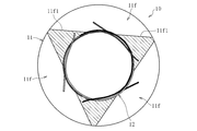
- FIG. 1 shows a foil bearing 10 according to a first embodiment of the present invention.
- the foil bearing 10 supports the shaft 2 inserted in the inner periphery in the radial direction.
- the foil bearing 10 is an air dynamic pressure bearing that uses air as a pressure generating fluid.
- the foil bearing 10 includes a foil holder 11 and one or more foils 12 attached to the inner peripheral surface 11 a of the foil holder 11.
- the foil bearing 10 in the illustrated example has three foils 12.
- the downstream side in the fluid flow direction with respect to the foil 12 when the shaft 2 is relatively rotated is referred to as “downstream side”, and the opposite side is referred to as “upstream side”.
- the three foils 12 have the same shape, but for ease of understanding, the foils 12 are shaded (or hatched density difference) in the drawing.
- the foil holder 11 is formed in a cylindrical shape with metal or resin.
- the inner peripheral surface 11a of the foil holder 11 is a cylindrical surface having a uniform diameter in the entire axial direction.
- the outer peripheral surface 11b of the foil holder 11 is fixed to a housing of a facility (for example, a turbo machine such as a gas turbine) in which the foil bearing 10 is incorporated.
- Grooves 11c into which the end portions of the foils 12 are inserted are formed at a plurality of locations (three locations in the illustrated example) spaced apart in the circumferential direction on the inner peripheral surface 11a of the foil holder 11.
- the groove 11 c extends in the axial direction, and both ends in the axial direction are open to both end surfaces 11 d of the foil holder 11.
- the foil 12 is formed of a metal having a high spring property and good workability, for example, steel or copper alloy.
- the foil 12 is formed by pressing or electric discharge machining a metal foil having a thickness of about 20 ⁇ m to 200 ⁇ m.
- the foil 12 is preferably formed of stainless steel or bronze.
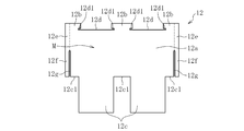
- the foil 12 includes a main body part M, and connection parts 12 e and locking parts 12 f provided on both axial sides of the main body part M.
- the foil 12 In a state before being attached to the foil holder 11, the foil 12 is provided on the same plane.
- FIG. 3 in the state where the foil 12 is attached to the inner peripheral surface 11a of the foil holder 11, the main body portion M of the foil 12 is provided in the axial region of the foil holder 11, and the connection portion 12e of the foil 12 and the engagement portion are connected.
- the stop portion 12f protrudes to both sides in the axial direction of the inner peripheral surface 11a of the foil holder 11. When attached to the foil holder 11, the entire area of the foil 12 is parallel to the axial direction.
- the body portion M of the foil 12 includes a top foil portion 12a, an insertion portion 12b provided on the downstream side (upper side in FIG. 2) of the top foil portion 12a, and an upstream side of the top foil portion 12a. And an underfoil portion 12c provided on the side (the lower side in FIG. 2).
- the surface on the inner diameter side of the top foil portion 12a functions as a bearing surface facing the outer peripheral surface 2a of the shaft 2 (see FIG. 1).
- the top foil portion 12a of the body portion M of each foil 12 is exposed on the inner peripheral side, and the insertion portion 12b and the underfoil portion 12c are behind the other foils 12 (outer diameter side). Arranged.
- the insertion part 12b extends downstream from the top foil part 12a.
- the insertion part 12b and the top foil part 12a are smoothly continuous in the circumferential direction.
- the insertion portions 12b are provided at a plurality of locations (three locations in the illustrated example) spaced apart in the axial direction.
- a recess 12d is provided between the plurality of insertion portions 12b in the axial direction.
- An axial cut 12d1 is provided at the corner of the recess 12d. Note that the cut 12d1 may be omitted unless particularly required.
- the underfoil portion 12c extends upstream from the top foil portion 12a.
- the underfoil portion 12c and the top foil portion 12a are smoothly continuous in the circumferential direction.
- the underfoil portions 12c are provided at a plurality of locations (two locations in the illustrated example) separated in the axial direction.
- Each underfoil portion 12c is provided in the same axial region as the recess 12d (including the cut 12d1).
- Concave portions 12c1 are provided between the axial directions of the plurality of underfoil portions 12c and on the axially outer side.
- each foil 12 is disposed between the top foil portion 12 a of the foil 12 adjacent to the upstream side and the inner peripheral surface 11 a of the foil holder 11.
- the top foil part 12a of each foil 12 is supported from the back by the underfoil part 12c of the foil 12 adjacent to the downstream.
- edges (concave portions 12d and concave portions 12c1) of the end portions in the circumferential direction of the top foil portions 12a of the adjacent foils 12 are engaged with each other in the circumferential direction and stick to each other.
- the top foil part 12a of each foil 12 protrudes to the outer diameter side, and is curved into a substantially cylindrical shape along the inner peripheral surface 11a of the foil holder 11.
- the foil 12 includes a connecting portion 12e smoothly connected to the main body M in the axial direction, and a locking portion 12f smoothly connected to the connecting portion 12e in the circumferential direction.
- the connection portion 12e and the locking portion 12f are provided in an axial region different from the main body portion M, and in the illustrated example, are provided on the outer side in the axial direction of the main body portion M, particularly on both sides in the axial direction of the main body portion M.
- the connecting portion 12e is continuous in the axial direction with, for example, a region including the downstream end portion of the main body M, specifically, the insertion portion 12b and the downstream region of the top foil portion 12a continuous on the upstream side. is doing.
- a conceptual boundary between the main body M and the connecting part 12e is indicated by a dotted line.
- the locking portion 12f is connected to the main body portion M through the connection portion 12e, and is separated from the main body portion M in the axial direction.
- a circumferential slit 12g is provided between the locking portion 12f and the main body M in the axial direction to divide them in the axial direction.
- the locking portion 12f in the illustrated example extends upstream from the connection portion 12e, and its upstream end is a free end.
- the entire locking portion 12f in the illustrated example is provided in the circumferential region of the top foil portion 12a.
- locking part 12f can be adjusted by changing the axial direction dimension and circumferential direction dimension of the latching
- the dimensions of each part may be set in consideration of these.
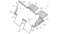
- the top foil portion 12 a and the under foil portion 12 c of the foil 12 are curved in a substantially cylindrical shape along the inner peripheral surface 11 a of the foil holder 11. Further, as shown in FIG. 4, the connecting portion 12e of the foil 12 is continuous with the main body portion M (top foil portion 12a) in the axial direction. Yes.
- the locking portion 12f of the foil 12 since the locking portion 12f of the foil 12 is separated from the main body portion M in the axial direction, it does not deform following the main body portion M. Moreover, since the latching
- the locking portion 12f has a flat plate shape that is smoothly continuous with the connecting portion 12e in the circumferential direction, and more specifically, the connection at the boundary between the connecting portion 12e and the locking portion 12f. It becomes flat form extended in the substantially tangential direction of the part 12e.
- the engaging portion 12f is displaced to the outer diameter side with respect to the inner peripheral surface 11a of the foil holder 11 as it goes upstream, and as a result, the engaging portion 12f is displaced from the inner peripheral surface 11a of the foil holder 11. Is also arranged on the outer diameter side (see FIGS. 1 and 4).
- the engaging portion 12f of the foil 12 and the end surface 11d of the foil holder 11 can be engaged in the axial direction, so that the foil 12 can be provided without providing a separate engaging member or bending the foil 12. And the axial displacement of the foil holder 11 can be prevented.
- the rear locking portion 12f that is not visible in FIGS. 3 and 4 also has the same configuration as described above, and can be engaged with the rear end surface of the foil holder 11 in the axial direction. . That is, the foil holder 11 is arranged between the pair of locking portions 12f provided at both ends of the foil 12 in the axial direction, and the foil holder 11 is sandwiched by both locking portions 12f from both sides in the axial direction. Thereby, since both the latching
- a cylindrical temporary assembly X is formed by combining three flat foils 12. Specifically, the underfoil portion 12c and the insertion portion 12b of the adjacent foil 12 are fitted together. That is, the underfoil portion 12 c of each foil 12 is inserted into the recess 12 d on the downstream side of the adjacent foil 12, and the insertion portion 12 b of each foil 12 is inserted into the recess 12 c 1 on the upstream side of the adjacent foil 12. Thereby, the three foils 12 are connected, and the temporary assembly X is formed.
- the temporary assembly X is inserted into the inner periphery of the foil holder 11 in a state of being rounded into a cylindrical shape.
- the locking portion 12f of each foil 12 does not deform following the main body portion M, and thus jumps out to the outer diameter side.
- the locking portion 12f (not visible in FIG. 6) on one axial side (the insertion direction leading side) of each foil 12 is elastically deformed to the inner diameter side with respect to the inner peripheral surface 11a of the foil holder 11 so that the foil is
- the temporary assembly X is inserted into the inner periphery of the foil holder 11 while avoiding interference with the holder 11.
- each foil 12 since the engaging portion 12f on the other axial side of each foil 12 is not inserted into the inner periphery of the foil holder 11, it is left protruding to the outer diameter side. In this state, the temporary assembly X is inserted into the inner periphery of the foil holder 11 while inserting the insertion portion 12b of each foil 12 into the groove 11c opened from the end surface of the foil holder 11 from the outside in the axial direction.
- each foil 12 passes the inner peripheral surface 11a of the foil holder 11, and will come out to an axial direction outer side
- the locking part 12f of the axial direction one side will be elastically flat. It restores and is arranged on the outer diameter side from the inner peripheral surface 11a of the foil holder 11.
- the locking portion 12f on the other axial side of each foil 12 is arranged in the immediate vicinity of the other end surface 11d in the axial direction of the foil holder 11 while being arranged on the outer diameter side of the inner peripheral surface 11a of the foil holder 11. Is done.
- locking part 12f and the end surface 11d of the foil holder 11 may be contact
- the foil 12 is provided with a locking portion 12f that is separated from the main body portion M in the axial direction and can be deformed in the radial direction independently of the main body portion M.
- the foil holder 11 protrudes outward in the axial direction from the inner peripheral surface 11 a and is arranged at a position where the foil holder 11 is not restrained from the outer diameter side.
- the engaging portion 12f is arranged on the outer diameter side of the inner peripheral surface 11a of the foil holder 11 by the elastic restoring force of the engaging portion 12f. Can do.
- a bearing gap R is formed between the inner diameter surface (bearing surface) of the top foil portion 12 a of each foil 12 of the foil bearing 10 and the outer peripheral surface 2 a of the shaft 2.
- the top foil part 12a of each foil 12 rides on the underfoil part 12c of the foil 12 adjacent to the downstream side.
- the insertion part 12b provided in the downstream edge part of each foil 12 is inserted in the groove
- the wedge-shaped bearing gap R having the gap width gradually narrowed toward the downstream side is formed, and air is pushed into the narrow side of the wedge-shaped bearing gap R, so that the air film of the bearing gap R is reduced.
- the pressure is increased, and the shaft 2 is supported in a non-contact manner in the radial direction by this pressure.
- the width of the bearing gap R is exaggerated.
- the top foil portion 12a of each foil 12 rides on the underfoil portion 12c of the other foil 12, and the vicinity of the downstream end of the top foil portion 12a is curved so as to protrude toward the inner diameter side.
- a spring property in the radial direction is imparted to the top foil portion 12a.
- the bearing surface of the top foil portion 12a of each foil 12 is arbitrarily deformed according to the operating conditions such as the load, the rotational speed of the shaft 2, the ambient temperature, etc., so the bearing gap R has an appropriate width according to the operating conditions. Automatically adjusted. Therefore, the bearing gap can be managed to the optimum width even under severe conditions such as high temperature and high speed rotation, and the shaft 2 can be stably supported.
- each foil 12 is not completely fixed to the foil holder 11 and can be moved minutely with respect to the foil holder 11. Therefore, while the shaft 2 is rotating, the foil 12 is pressed against the foil holder 11 due to the influence of the air film formed in the bearing gap, and accordingly, the foil 12 and the foil holder 11, particularly the underfoil of each foil 12, are pressed. Minute sliding occurs between the outer diameter surface of the portion 12 c and the inner peripheral surface 11 a of the foil holder 11, or between the insertion portion 12 b of each foil 12 and the groove 11 c of the foil holder 11. The vibration of the shaft 2 can be attenuated by the frictional energy generated by the minute sliding.
- each foil 12 and the outer peripheral surface of the shaft 2 slide in contact with each other at the time of low-speed rotation immediately before the shaft 2 stops or immediately after the shaft 2 starts.
- a coating made of PTFE, DLC, titanium aluminum nitride, or the like is provided on the bearing surface of each foil 12, the bearing surface can be prevented from being worn.
- the above-described coating may be formed on one or both of them.
- a tungsten disulfide film or a molybdenum disulfide film may be used as a film provided on the foil 12 or the foil holder 11.
- a region 12g1 having a wide axial width is provided at the downstream end of the slit 12g.
- stress concentration at the downstream end of the slit 12g is alleviated, and damage to the foil 12 can be prevented.
- each foil 12 extends downstream from the connecting portion 12e, and the downstream end is a free end.
- the locking portion 12f is provided on the downstream side of the main body portion M.
- a connecting portion 12e is provided continuously outside the insertion portion 12b of each foil 12 in the axial direction, and a locking portion 12f extends continuously downstream of the connecting portion 12e.
- connection part 12e is connected to the downstream end of the main body part M of each foil 12, but the connection part is not limited to this, and is connected to the upstream end part or the circumferential intermediate part of the main body part M. 12e may be connected.
- a recess 11 e is provided at the axial end of the inner peripheral surface 11 a of the foil holder 11.
- the recess 11e in the illustrated example is continuously provided on the entire circumference.
- the axial dimension of the recess 11e is slightly larger than the axial dimension of the connection part 12e and the locking part 12f of the foil 12.
- the connecting portion 12e and the locking portion 12f of the foil 12 are accommodated in the axial direction region of the recess 11e (see FIG. 11).
- locking part 12f of the foil 12 do not protrude to the axial direction outer side from the foil holder 11, when incorporating the foil bearing 10 in a turbomachine etc., the connection part 12e and the latching
- the locking portion 12f of the foil 12 can be engaged with an end surface 11e1 (shoulder surface) formed in the concave portion 11e of the foil holder 11 in the axial direction.
- the recess 11e on the inner peripheral surface of the foil holder 11 is not necessarily formed on the entire periphery.
- the recesses 11e may be provided at a plurality of locations separated in the circumferential direction.
- the locking portion 12f of each foil 12 is accommodated in the axial region of each recess 11e.
- locking part 12f of the foil 12 may be separated from the bottom face (surface parallel to an axial direction) of the recessed part 11e of the foil holder 11, and may be extended in flat form.
- the locking portion 12f may be curved toward the inner diameter side by contacting the bottom surface of the recess 11e.
- the locking portions 12f and the connection portions 12e are provided on both sides in the axial direction of the main body portion M of the foil 12 . If there is no particular need, any of the locking portions 12f and the connection portions 12e. May be omitted, and the locking portion 12f and the connecting portion 12e may be provided only on one side in the axial direction of the body portion M of the foil 12.
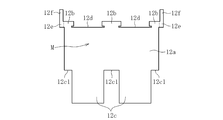
- the connecting portion 12e and the locking portion 12f of the foil 12 are provided in the axially intermediate portion of the foil 12 (in the illustrated example, the axially central portion).
- the main body portions M are continuously provided on both sides in the axial direction of the connecting portion 12e.
- the connection part 12e is following the area
- the locking portion 12f extends upstream from the connection portion 12e. Between the latching
- the foil 12 is attached to the foil holder 11 shown in FIG.
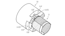
- a concave portion is provided in the axially intermediate portion of the inner peripheral surface 11 a of the foil holder 11.
- the concave portion is formed on the inner peripheral surface 11 a and the outer peripheral surface 11 b of the foil holder 11 as a concave portion in the axial direction intermediate portion (axial central portion in the illustrated example).
- An open through-hole 11f is provided.
- the same number of through holes 11f as the locking portions 12f of the foil 12 are provided, and in the illustrated example, the through holes 11f are provided at three locations at equal intervals in the circumferential direction.
- Side walls 11f1 on both sides in the circumferential direction of each through hole 11f are concave curved surfaces parallel to the axial direction.
- side walls 11f1 on both sides in the circumferential direction of each through hole 11f are provided on the same cylindrical surface.
- the foil bearing 10 of the present embodiment is assembled in the same procedure as that of the first embodiment. Specifically, first, as shown in FIG. 17, the underfoil portion 12c and the insertion portion 12b of the three foils 12 are fitted together to form a cylindrical temporary assembly X.
- the temporary assembly X is inserted into the inner circumference of the foil holder 11 in a state of being rounded into a cylindrical shape.
- the temporary assembly X is removed from the foil holder 11 while elastically deforming the locking portion 12f that protrudes from the cylindrical assembly X to the outer diameter side toward the inner diameter side of the inner peripheral surface 11a of the foil holder 11.
- 11 is inserted into the inner periphery.
- the locking portion 12f is fitted into the through hole 11f in the central portion in the axial direction of the foil holder 11, the locking portion 12f is elastically restored to a flat plate shape as shown in FIGS. 19 and 20, and the foil holder 11 is arranged closer to the outer diameter side than the inner peripheral surface 11a.
- the engaging portion 12f of the foil 12 is accommodated in the through hole 11f of the foil holder 11, and the side walls 11f2 on both sides in the axial direction of the through hole 11f (in FIGS. 19 and 20, only one side wall 11f2 in the axial direction is shown).
- the locking portion 12f is disposed between the axial directions. As a result, the locking portion 12f can be engaged with the side walls 11f2 on both axial sides of the through hole 11f, and the foil 12 is prevented from coming off from the foil holder 11 in the axial direction.
- the fluid (air) in the bearing gap R flows in the rotation direction of the shaft 2, as shown by the arrow Q direction in FIG. In particular, it flows into the bearing gap R.
- the amount of air in the bearing gap R increases and the pressure of the air film in the bearing gap R is further increased, so that the load capacity of the foil bearing 10 is increased.
- the outside air flows into the bearing gap R, so that the bearing surface (top foil portion 12a) can be cooled.
- the side walls 11f1 on both sides in the circumferential direction of the through hole 11f of the foil holder 11 are concave curved surfaces parallel to the axial direction. As a result, for example, as shown in FIG.
- the external air is passed through the through-hole 11f when the shaft 2 is rotated. Since it tends to flow into the bearing gap R, it is easy to improve the bearing rigidity and cool the bearing surface.
- the communication path through-hole etc. which connects said through-hole 11f and the exterior is provided in the housing to which the outer peripheral surface of the foil holder 11 is attached, external air will more easily flow into the bearing gap R. .
- circumferential position, the axial position, and the number of the locking portion 12f and the through hole 11f are not limited to the above, and may be increased or decreased.
- the foil bearing to which the present invention is applied is not limited to the above.
- the present invention may be applied to a bump-type foil bearing having a top foil having a bearing surface and a back foil that elastically supports the top foil from behind.
- the foil having the locking portion and the connecting portion which is a characteristic configuration of the present invention, may be a top foil or a back foil.
- the foil bearing 10 is fixed and the shaft 2 is rotated.
- the present invention is not limited to this, and the foil bearing 10 may be rotated while the shaft 2 is fixed.
- the foil bearing 10 is rotated, the foil 12 may be damaged by centrifugal force. Therefore, the foil bearing 10 is preferably fixed.
- the foil bearing 10 shown above can be used as a bearing for a vehicle such as an automobile or a bearing for industrial equipment, in addition to a turbo machine such as a gas turbine or a turbocharger (supercharger). .
- foil bearing described above can be used not only as an air dynamic pressure bearing using air as a pressure generating fluid but also as an oil dynamic pressure bearing using lubricating oil as a pressure generating fluid.
Landscapes
- Engineering & Computer Science (AREA)
- General Engineering & Computer Science (AREA)
- Mechanical Engineering (AREA)
- Physics & Mathematics (AREA)
- Fluid Mechanics (AREA)
- Support Of The Bearing (AREA)
Abstract
La présente invention concerne un palier-feuille (10) qui est pourvu : d'un support de feuille cylindrique (11) ; d'une feuille (12) qui est attachée à la surface périphérique interne (11a) du support de feuille (11). La feuille (12) est pourvue : d'une section principale (M) qui est incurvée le long de la surface périphérique interne (11a) du support de feuille (11) ; d'une section de liaison (12e) qui est continue de façon axiale avec la section principale (M) et incurvée de la même manière que la section principale (M) ; d'une section de mise en prise (12f) qui est continue de manière périphérique avec la section de liaison (12e), qui est disposée sur le côté de diamètre externe de la surface périphérique interne (11a) du support de feuille (11), et qui peut venir en prise de façon axiale avec le support de feuille (11).
Applications Claiming Priority (4)
| Application Number | Priority Date | Filing Date | Title |
|---|---|---|---|
| JP2016-069016 | 2016-03-30 | ||
| JP2016069016 | 2016-03-30 | ||
| JP2016195736A JP2017187166A (ja) | 2016-03-30 | 2016-10-03 | フォイル軸受 |
| JP2016-195736 | 2016-10-03 |
Publications (1)
| Publication Number | Publication Date |
|---|---|
| WO2017169676A1 true WO2017169676A1 (fr) | 2017-10-05 |
Family
ID=59964210
Family Applications (1)
| Application Number | Title | Priority Date | Filing Date |
|---|---|---|---|
| PCT/JP2017/009866 WO2017169676A1 (fr) | 2016-03-30 | 2017-03-13 | Palier-feuille |
Country Status (1)
| Country | Link |
|---|---|
| WO (1) | WO2017169676A1 (fr) |
Cited By (1)
| Publication number | Priority date | Publication date | Assignee | Title |
|---|---|---|---|---|
| JP2022540995A (ja) * | 2019-07-16 | 2022-09-21 | ロベルト・ボッシュ・ゲゼルシャフト・ミト・ベシュレンクテル・ハフツング | フォイル軸受 |
Citations (5)
| Publication number | Priority date | Publication date | Assignee | Title |
|---|---|---|---|---|
| JP2008261496A (ja) * | 2007-04-12 | 2008-10-30 | Hamilton Sundstrand Corp | 流体力学的流体膜ジャーナル軸受アッセンブリおよびその製造方法 |
| JP2011144846A (ja) * | 2010-01-13 | 2011-07-28 | Shimadzu Corp | 動圧気体軸受 |
| WO2013042713A1 (fr) * | 2011-09-22 | 2013-03-28 | Ntn株式会社 | Palier à feuilles |
| WO2014014036A1 (fr) * | 2012-07-18 | 2014-01-23 | 株式会社Ihi | Palier à feuilles radiales |
| WO2015026655A1 (fr) * | 2013-08-20 | 2015-02-26 | Borgwarner Inc. | Agencement de palier à air |
-
2017
- 2017-03-13 WO PCT/JP2017/009866 patent/WO2017169676A1/fr active Application Filing
Patent Citations (5)
| Publication number | Priority date | Publication date | Assignee | Title |
|---|---|---|---|---|
| JP2008261496A (ja) * | 2007-04-12 | 2008-10-30 | Hamilton Sundstrand Corp | 流体力学的流体膜ジャーナル軸受アッセンブリおよびその製造方法 |
| JP2011144846A (ja) * | 2010-01-13 | 2011-07-28 | Shimadzu Corp | 動圧気体軸受 |
| WO2013042713A1 (fr) * | 2011-09-22 | 2013-03-28 | Ntn株式会社 | Palier à feuilles |
| WO2014014036A1 (fr) * | 2012-07-18 | 2014-01-23 | 株式会社Ihi | Palier à feuilles radiales |
| WO2015026655A1 (fr) * | 2013-08-20 | 2015-02-26 | Borgwarner Inc. | Agencement de palier à air |
Cited By (2)
| Publication number | Priority date | Publication date | Assignee | Title |
|---|---|---|---|---|
| JP2022540995A (ja) * | 2019-07-16 | 2022-09-21 | ロベルト・ボッシュ・ゲゼルシャフト・ミト・ベシュレンクテル・ハフツング | フォイル軸受 |
| JP7490041B2 (ja) | 2019-07-16 | 2024-05-24 | ロベルト・ボッシュ・ゲゼルシャフト・ミト・ベシュレンクテル・ハフツング | フォイル軸受 |
Similar Documents
| Publication | Publication Date | Title |
|---|---|---|
| JP6479456B2 (ja) | フォイル、フォイル軸受、及びフォイル軸受の組立方法 | |
| WO2015087675A1 (fr) | Palier à feuilles, et unité de palier à feuilles et turbomachine comportant chacun ce dernier | |
| US8414191B2 (en) | Keyless/grooveless foil bearing with fold over tab | |
| JP6615573B2 (ja) | スラストフォイル軸受 | |
| WO2018051867A1 (fr) | Joint mécanique | |
| EP2818738A1 (fr) | Palier à patins oscillants | |
| WO2013042713A1 (fr) | Palier à feuilles | |
| JP2013087789A (ja) | ラジアルフォイル軸受 | |
| JP2017187166A (ja) | フォイル軸受 | |
| WO2017086190A1 (fr) | Palier à feuilles | |
| WO2018016268A1 (fr) | Palier à feuilles | |
| WO2017169676A1 (fr) | Palier-feuille | |
| JP6305748B2 (ja) | フォイル軸受と、これを有するフォイル軸受ユニット及びターボ機械 | |
| WO2019017134A1 (fr) | Palier à feuille | |
| JP2017172764A (ja) | フォイル軸受 | |
| JP6541946B2 (ja) | フォイル軸受及びこれに設けられるフォイル | |
| JP2012072817A (ja) | フォイル軸受 | |
| JP6629042B2 (ja) | フォイル軸受 | |
| WO2018116740A1 (fr) | Palier à feuilles | |
| JP6693945B2 (ja) | フォイル軸受、およびフォイル軸受装置 | |
| JP2020041589A (ja) | フォイル軸受 | |
| JP6440999B2 (ja) | フォイル軸受及びこれに設けられるフォイル | |
| WO2017051658A1 (fr) | Palier à feuilles et son procédé de fabrication | |
| WO2016031465A1 (fr) | Palier à feuilles et feuille disposée dans celui-ci | |
| JP6324774B2 (ja) | フォイル軸受及びこれを備えたターボ機械 |
Legal Events
| Date | Code | Title | Description |
|---|---|---|---|
| NENP | Non-entry into the national phase |
Ref country code: DE |
|
| 121 | Ep: the epo has been informed by wipo that ep was designated in this application |
Ref document number: 17774220 Country of ref document: EP Kind code of ref document: A1 |
|
| 122 | Ep: pct application non-entry in european phase |
Ref document number: 17774220 Country of ref document: EP Kind code of ref document: A1 |