WO2017169676A1 - Foil bearing - Google Patents
Foil bearing Download PDFInfo
- Publication number
- WO2017169676A1 WO2017169676A1 PCT/JP2017/009866 JP2017009866W WO2017169676A1 WO 2017169676 A1 WO2017169676 A1 WO 2017169676A1 JP 2017009866 W JP2017009866 W JP 2017009866W WO 2017169676 A1 WO2017169676 A1 WO 2017169676A1
- Authority
- WO
- WIPO (PCT)
- Prior art keywords
- foil
- holder
- bearing
- peripheral surface
- axial direction
- Prior art date
Links
Images


Classifications
-
- F—MECHANICAL ENGINEERING; LIGHTING; HEATING; WEAPONS; BLASTING
- F16—ENGINEERING ELEMENTS AND UNITS; GENERAL MEASURES FOR PRODUCING AND MAINTAINING EFFECTIVE FUNCTIONING OF MACHINES OR INSTALLATIONS; THERMAL INSULATION IN GENERAL
- F16C—SHAFTS; FLEXIBLE SHAFTS; ELEMENTS OR CRANKSHAFT MECHANISMS; ROTARY BODIES OTHER THAN GEARING ELEMENTS; BEARINGS
- F16C17/00—Sliding-contact bearings for exclusively rotary movement
- F16C17/02—Sliding-contact bearings for exclusively rotary movement for radial load only
- F16C17/024—Sliding-contact bearings for exclusively rotary movement for radial load only with flexible leaves to create hydrodynamic wedge, e.g. radial foil bearings
-
- F—MECHANICAL ENGINEERING; LIGHTING; HEATING; WEAPONS; BLASTING
- F16—ENGINEERING ELEMENTS AND UNITS; GENERAL MEASURES FOR PRODUCING AND MAINTAINING EFFECTIVE FUNCTIONING OF MACHINES OR INSTALLATIONS; THERMAL INSULATION IN GENERAL
- F16C—SHAFTS; FLEXIBLE SHAFTS; ELEMENTS OR CRANKSHAFT MECHANISMS; ROTARY BODIES OTHER THAN GEARING ELEMENTS; BEARINGS
- F16C43/00—Assembling bearings
- F16C43/02—Assembling sliding-contact bearings
-
- F—MECHANICAL ENGINEERING; LIGHTING; HEATING; WEAPONS; BLASTING
- F16—ENGINEERING ELEMENTS AND UNITS; GENERAL MEASURES FOR PRODUCING AND MAINTAINING EFFECTIVE FUNCTIONING OF MACHINES OR INSTALLATIONS; THERMAL INSULATION IN GENERAL
- F16C—SHAFTS; FLEXIBLE SHAFTS; ELEMENTS OR CRANKSHAFT MECHANISMS; ROTARY BODIES OTHER THAN GEARING ELEMENTS; BEARINGS
- F16C2360/00—Engines or pumps
-
- F—MECHANICAL ENGINEERING; LIGHTING; HEATING; WEAPONS; BLASTING
- F16—ENGINEERING ELEMENTS AND UNITS; GENERAL MEASURES FOR PRODUCING AND MAINTAINING EFFECTIVE FUNCTIONING OF MACHINES OR INSTALLATIONS; THERMAL INSULATION IN GENERAL
- F16C—SHAFTS; FLEXIBLE SHAFTS; ELEMENTS OR CRANKSHAFT MECHANISMS; ROTARY BODIES OTHER THAN GEARING ELEMENTS; BEARINGS
- F16C27/00—Elastic or yielding bearings or bearing supports, for exclusively rotary movement
- F16C27/02—Sliding-contact bearings
Definitions
- the present invention relates to a foil bearing.
- the foil bearing is configured to support a load by forming a bearing surface with a metal thin plate (foil) having low rigidity with respect to bending and allowing the deflection of the bearing surface.
- the foil bearing has a feature that the bearing gap is automatically adjusted to an appropriate width according to the operating conditions such as the rotational speed, load, and ambient temperature of the shaft as the foil is bent.
- ⁇ Foil bearings generally have a foil attached to the inner peripheral surface of a cylindrical foil holder.
- the shaft When assembling or maintaining this foil bearing, the shaft is inserted into the inner periphery of the foil bearing or pulled out from the inner periphery of the foil bearing. At this time, the shaft and the foil slide, and the foil is in the foil holder. There is a risk of shifting in the axial direction. Further, when the shaft rotates at a low speed immediately before stopping or immediately after starting, a force due to sliding with the shaft acts on the foil, and when the shaft rotates at a high speed, a shearing force due to the viscosity of the fluid flowing through the bearing gap acts on the foil. If the force acting on these foils includes an axial component, the foil may be displaced in the axial direction with respect to the foil holder.
- the foil is welded and fixed to the inner peripheral surface of the foil holder, the above-mentioned problems can be prevented, but the foil may be distorted by heat during welding. Since the bearing gap formed between the bearing surface of the foil and the outer peripheral surface of the shaft is usually a minimum width of about several tens of ⁇ m, any slight distortion in the foil will adversely affect the accuracy of the bearing gap. .
- a locking member is attached to the foil holder, and the locking member and the foil are engaged in the axial direction, thereby preventing the axial displacement of the foil and the foil holder.
- a protruding portion 110 protruding to the outer diameter side is provided on the foil 104, and the protruding portion 110 and the foil holder are engaged in the axial direction.
- the projecting portion 110 is formed by bending an extending portion obtained by extending a partial region in the circumferential direction of the foil 104 in the axial direction to the outer diameter side.
- an object of the present invention is to prevent axial displacement between the foil and the foil holder without incurring high costs due to an increase in the number of parts and man-hours, and complexity of the foil design.
- the present invention includes a cylindrical foil holder and a foil attached to the inner peripheral surface of the foil holder, and supports a shaft inserted in the inner periphery so as to be relatively rotatable.
- a foil bearing wherein the foil is curved along an inner peripheral surface of the foil holder, a connection portion that is continuous with the body portion in the axial direction and is curved in the same manner as the body portion, and the connection A foil bearing is provided that includes a locking portion that is continuous with the portion in the circumferential direction, is disposed on the outer diameter side of the inner circumferential surface of the foil holder, and is engageable with the foil holder in the axial direction.
- the main body portion and the locking portion of the foil are connected via the connecting portion that is continuous with the main body portion in the axial direction and continuous with the locking portion in the circumferential direction.
- the main body portion of the foil is curved along the inner peripheral surface of the foil holder, and the connecting portion of the foil is curved following the main body portion.
- the engaging portion of the foil is discontinuous with the main body portion in the axial direction, it does not bend following the main body portion, and tries to be elastically restored to a flat plate shape that is smoothly continuous with the connecting portion. Therefore, if there is a sufficient space on the outer diameter side of the locking portion, the locking portion is arranged on the outer diameter side of the inner peripheral surface of the foil holder in a state of being smoothly connected to the connection portion.
- locking part can be easily arrange
- the both locking portions and the foil holder can be oriented in any axial direction. Because of the engagement, the movement of the foil relative to the foil holder in both axial directions can be restricted.
- a recess may be provided in the axially intermediate portion of the inner peripheral surface of the foil holder, and a foil locking portion may be disposed between the side walls on both sides in the axial direction of the recess.
- the movement of the foil to the both sides in the axial direction relative to the foil holder can be restricted by engaging the engaging portions of the foil with the side walls on both sides in the axial direction of the recess.
- This recessed part can be comprised by the through-hole of radial direction, for example. In this case, during relative rotation of the shaft, external air is drawn into the inner periphery of the foil bearing, particularly the bearing gap, through the through hole of the foil holder.
- a bearing surface can be cooled by supplying external air to a bearing clearance via a through-hole. At this time, if the side walls on both sides in the circumferential direction of the through hole are concave curved surfaces parallel to the axial direction, outside air is likely to be drawn into the inner circumference of the foil bearing along the concave curved surface. The amount of fluid further increases, and the load capacity of the foil bearing further increases.
- the main body of the foil can be provided with a bearing surface that faces the outer peripheral surface of the shaft.
- the bearing surfaces provided in each main body are provided at two locations separated in the axial direction, so that both bearing surfaces are continuous in the axial direction. The moment stiffness of the foil bearing increases more than in the case.
- the foil bearing further includes a top foil having a bearing surface
- the foil may be a back foil that supports the top foil from behind.
- the foil and the foil holder can be engaged in the axial direction without increasing the cost due to the increase in the number of parts and man-hours or complicating the design of the foil. , It is possible to prevent the positional deviation between the two in the axial direction.
- FIG. 9 is a perspective view of a foil bearing having the foil of FIG. 8. It is a perspective view of the foil bearing which concerns on 4th embodiment of this invention.
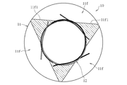
- FIG. 1 shows a foil bearing 10 according to a first embodiment of the present invention.
- the foil bearing 10 supports the shaft 2 inserted in the inner periphery in the radial direction.
- the foil bearing 10 is an air dynamic pressure bearing that uses air as a pressure generating fluid.
- the foil bearing 10 includes a foil holder 11 and one or more foils 12 attached to the inner peripheral surface 11 a of the foil holder 11.
- the foil bearing 10 in the illustrated example has three foils 12.
- the downstream side in the fluid flow direction with respect to the foil 12 when the shaft 2 is relatively rotated is referred to as “downstream side”, and the opposite side is referred to as “upstream side”.
- the three foils 12 have the same shape, but for ease of understanding, the foils 12 are shaded (or hatched density difference) in the drawing.
- the foil holder 11 is formed in a cylindrical shape with metal or resin.
- the inner peripheral surface 11a of the foil holder 11 is a cylindrical surface having a uniform diameter in the entire axial direction.
- the outer peripheral surface 11b of the foil holder 11 is fixed to a housing of a facility (for example, a turbo machine such as a gas turbine) in which the foil bearing 10 is incorporated.
- Grooves 11c into which the end portions of the foils 12 are inserted are formed at a plurality of locations (three locations in the illustrated example) spaced apart in the circumferential direction on the inner peripheral surface 11a of the foil holder 11.
- the groove 11 c extends in the axial direction, and both ends in the axial direction are open to both end surfaces 11 d of the foil holder 11.
- the foil 12 is formed of a metal having a high spring property and good workability, for example, steel or copper alloy.
- the foil 12 is formed by pressing or electric discharge machining a metal foil having a thickness of about 20 ⁇ m to 200 ⁇ m.
- the foil 12 is preferably formed of stainless steel or bronze.
- the foil 12 includes a main body part M, and connection parts 12 e and locking parts 12 f provided on both axial sides of the main body part M.
- the foil 12 In a state before being attached to the foil holder 11, the foil 12 is provided on the same plane.
- FIG. 3 in the state where the foil 12 is attached to the inner peripheral surface 11a of the foil holder 11, the main body portion M of the foil 12 is provided in the axial region of the foil holder 11, and the connection portion 12e of the foil 12 and the engagement portion are connected.
- the stop portion 12f protrudes to both sides in the axial direction of the inner peripheral surface 11a of the foil holder 11. When attached to the foil holder 11, the entire area of the foil 12 is parallel to the axial direction.
- the body portion M of the foil 12 includes a top foil portion 12a, an insertion portion 12b provided on the downstream side (upper side in FIG. 2) of the top foil portion 12a, and an upstream side of the top foil portion 12a. And an underfoil portion 12c provided on the side (the lower side in FIG. 2).
- the surface on the inner diameter side of the top foil portion 12a functions as a bearing surface facing the outer peripheral surface 2a of the shaft 2 (see FIG. 1).
- the top foil portion 12a of the body portion M of each foil 12 is exposed on the inner peripheral side, and the insertion portion 12b and the underfoil portion 12c are behind the other foils 12 (outer diameter side). Arranged.
- the insertion part 12b extends downstream from the top foil part 12a.
- the insertion part 12b and the top foil part 12a are smoothly continuous in the circumferential direction.
- the insertion portions 12b are provided at a plurality of locations (three locations in the illustrated example) spaced apart in the axial direction.
- a recess 12d is provided between the plurality of insertion portions 12b in the axial direction.
- An axial cut 12d1 is provided at the corner of the recess 12d. Note that the cut 12d1 may be omitted unless particularly required.
- the underfoil portion 12c extends upstream from the top foil portion 12a.
- the underfoil portion 12c and the top foil portion 12a are smoothly continuous in the circumferential direction.
- the underfoil portions 12c are provided at a plurality of locations (two locations in the illustrated example) separated in the axial direction.
- Each underfoil portion 12c is provided in the same axial region as the recess 12d (including the cut 12d1).
- Concave portions 12c1 are provided between the axial directions of the plurality of underfoil portions 12c and on the axially outer side.
- each foil 12 is disposed between the top foil portion 12 a of the foil 12 adjacent to the upstream side and the inner peripheral surface 11 a of the foil holder 11.
- the top foil part 12a of each foil 12 is supported from the back by the underfoil part 12c of the foil 12 adjacent to the downstream.
- edges (concave portions 12d and concave portions 12c1) of the end portions in the circumferential direction of the top foil portions 12a of the adjacent foils 12 are engaged with each other in the circumferential direction and stick to each other.
- the top foil part 12a of each foil 12 protrudes to the outer diameter side, and is curved into a substantially cylindrical shape along the inner peripheral surface 11a of the foil holder 11.
- the foil 12 includes a connecting portion 12e smoothly connected to the main body M in the axial direction, and a locking portion 12f smoothly connected to the connecting portion 12e in the circumferential direction.
- the connection portion 12e and the locking portion 12f are provided in an axial region different from the main body portion M, and in the illustrated example, are provided on the outer side in the axial direction of the main body portion M, particularly on both sides in the axial direction of the main body portion M.
- the connecting portion 12e is continuous in the axial direction with, for example, a region including the downstream end portion of the main body M, specifically, the insertion portion 12b and the downstream region of the top foil portion 12a continuous on the upstream side. is doing.
- a conceptual boundary between the main body M and the connecting part 12e is indicated by a dotted line.
- the locking portion 12f is connected to the main body portion M through the connection portion 12e, and is separated from the main body portion M in the axial direction.
- a circumferential slit 12g is provided between the locking portion 12f and the main body M in the axial direction to divide them in the axial direction.
- the locking portion 12f in the illustrated example extends upstream from the connection portion 12e, and its upstream end is a free end.
- the entire locking portion 12f in the illustrated example is provided in the circumferential region of the top foil portion 12a.
- locking part 12f can be adjusted by changing the axial direction dimension and circumferential direction dimension of the latching
- the dimensions of each part may be set in consideration of these.
- the top foil portion 12 a and the under foil portion 12 c of the foil 12 are curved in a substantially cylindrical shape along the inner peripheral surface 11 a of the foil holder 11. Further, as shown in FIG. 4, the connecting portion 12e of the foil 12 is continuous with the main body portion M (top foil portion 12a) in the axial direction. Yes.
- the locking portion 12f of the foil 12 since the locking portion 12f of the foil 12 is separated from the main body portion M in the axial direction, it does not deform following the main body portion M. Moreover, since the latching
- the locking portion 12f has a flat plate shape that is smoothly continuous with the connecting portion 12e in the circumferential direction, and more specifically, the connection at the boundary between the connecting portion 12e and the locking portion 12f. It becomes flat form extended in the substantially tangential direction of the part 12e.
- the engaging portion 12f is displaced to the outer diameter side with respect to the inner peripheral surface 11a of the foil holder 11 as it goes upstream, and as a result, the engaging portion 12f is displaced from the inner peripheral surface 11a of the foil holder 11. Is also arranged on the outer diameter side (see FIGS. 1 and 4).
- the engaging portion 12f of the foil 12 and the end surface 11d of the foil holder 11 can be engaged in the axial direction, so that the foil 12 can be provided without providing a separate engaging member or bending the foil 12. And the axial displacement of the foil holder 11 can be prevented.
- the rear locking portion 12f that is not visible in FIGS. 3 and 4 also has the same configuration as described above, and can be engaged with the rear end surface of the foil holder 11 in the axial direction. . That is, the foil holder 11 is arranged between the pair of locking portions 12f provided at both ends of the foil 12 in the axial direction, and the foil holder 11 is sandwiched by both locking portions 12f from both sides in the axial direction. Thereby, since both the latching
- a cylindrical temporary assembly X is formed by combining three flat foils 12. Specifically, the underfoil portion 12c and the insertion portion 12b of the adjacent foil 12 are fitted together. That is, the underfoil portion 12 c of each foil 12 is inserted into the recess 12 d on the downstream side of the adjacent foil 12, and the insertion portion 12 b of each foil 12 is inserted into the recess 12 c 1 on the upstream side of the adjacent foil 12. Thereby, the three foils 12 are connected, and the temporary assembly X is formed.
- the temporary assembly X is inserted into the inner periphery of the foil holder 11 in a state of being rounded into a cylindrical shape.
- the locking portion 12f of each foil 12 does not deform following the main body portion M, and thus jumps out to the outer diameter side.
- the locking portion 12f (not visible in FIG. 6) on one axial side (the insertion direction leading side) of each foil 12 is elastically deformed to the inner diameter side with respect to the inner peripheral surface 11a of the foil holder 11 so that the foil is
- the temporary assembly X is inserted into the inner periphery of the foil holder 11 while avoiding interference with the holder 11.
- each foil 12 since the engaging portion 12f on the other axial side of each foil 12 is not inserted into the inner periphery of the foil holder 11, it is left protruding to the outer diameter side. In this state, the temporary assembly X is inserted into the inner periphery of the foil holder 11 while inserting the insertion portion 12b of each foil 12 into the groove 11c opened from the end surface of the foil holder 11 from the outside in the axial direction.
- each foil 12 passes the inner peripheral surface 11a of the foil holder 11, and will come out to an axial direction outer side
- the locking part 12f of the axial direction one side will be elastically flat. It restores and is arranged on the outer diameter side from the inner peripheral surface 11a of the foil holder 11.
- the locking portion 12f on the other axial side of each foil 12 is arranged in the immediate vicinity of the other end surface 11d in the axial direction of the foil holder 11 while being arranged on the outer diameter side of the inner peripheral surface 11a of the foil holder 11. Is done.
- locking part 12f and the end surface 11d of the foil holder 11 may be contact
- the foil 12 is provided with a locking portion 12f that is separated from the main body portion M in the axial direction and can be deformed in the radial direction independently of the main body portion M.
- the foil holder 11 protrudes outward in the axial direction from the inner peripheral surface 11 a and is arranged at a position where the foil holder 11 is not restrained from the outer diameter side.
- the engaging portion 12f is arranged on the outer diameter side of the inner peripheral surface 11a of the foil holder 11 by the elastic restoring force of the engaging portion 12f. Can do.
- a bearing gap R is formed between the inner diameter surface (bearing surface) of the top foil portion 12 a of each foil 12 of the foil bearing 10 and the outer peripheral surface 2 a of the shaft 2.
- the top foil part 12a of each foil 12 rides on the underfoil part 12c of the foil 12 adjacent to the downstream side.
- the insertion part 12b provided in the downstream edge part of each foil 12 is inserted in the groove
- the wedge-shaped bearing gap R having the gap width gradually narrowed toward the downstream side is formed, and air is pushed into the narrow side of the wedge-shaped bearing gap R, so that the air film of the bearing gap R is reduced.
- the pressure is increased, and the shaft 2 is supported in a non-contact manner in the radial direction by this pressure.
- the width of the bearing gap R is exaggerated.
- the top foil portion 12a of each foil 12 rides on the underfoil portion 12c of the other foil 12, and the vicinity of the downstream end of the top foil portion 12a is curved so as to protrude toward the inner diameter side.
- a spring property in the radial direction is imparted to the top foil portion 12a.
- the bearing surface of the top foil portion 12a of each foil 12 is arbitrarily deformed according to the operating conditions such as the load, the rotational speed of the shaft 2, the ambient temperature, etc., so the bearing gap R has an appropriate width according to the operating conditions. Automatically adjusted. Therefore, the bearing gap can be managed to the optimum width even under severe conditions such as high temperature and high speed rotation, and the shaft 2 can be stably supported.
- each foil 12 is not completely fixed to the foil holder 11 and can be moved minutely with respect to the foil holder 11. Therefore, while the shaft 2 is rotating, the foil 12 is pressed against the foil holder 11 due to the influence of the air film formed in the bearing gap, and accordingly, the foil 12 and the foil holder 11, particularly the underfoil of each foil 12, are pressed. Minute sliding occurs between the outer diameter surface of the portion 12 c and the inner peripheral surface 11 a of the foil holder 11, or between the insertion portion 12 b of each foil 12 and the groove 11 c of the foil holder 11. The vibration of the shaft 2 can be attenuated by the frictional energy generated by the minute sliding.
- each foil 12 and the outer peripheral surface of the shaft 2 slide in contact with each other at the time of low-speed rotation immediately before the shaft 2 stops or immediately after the shaft 2 starts.
- a coating made of PTFE, DLC, titanium aluminum nitride, or the like is provided on the bearing surface of each foil 12, the bearing surface can be prevented from being worn.
- the above-described coating may be formed on one or both of them.
- a tungsten disulfide film or a molybdenum disulfide film may be used as a film provided on the foil 12 or the foil holder 11.
- a region 12g1 having a wide axial width is provided at the downstream end of the slit 12g.
- stress concentration at the downstream end of the slit 12g is alleviated, and damage to the foil 12 can be prevented.
- each foil 12 extends downstream from the connecting portion 12e, and the downstream end is a free end.
- the locking portion 12f is provided on the downstream side of the main body portion M.
- a connecting portion 12e is provided continuously outside the insertion portion 12b of each foil 12 in the axial direction, and a locking portion 12f extends continuously downstream of the connecting portion 12e.
- connection part 12e is connected to the downstream end of the main body part M of each foil 12, but the connection part is not limited to this, and is connected to the upstream end part or the circumferential intermediate part of the main body part M. 12e may be connected.
- a recess 11 e is provided at the axial end of the inner peripheral surface 11 a of the foil holder 11.
- the recess 11e in the illustrated example is continuously provided on the entire circumference.
- the axial dimension of the recess 11e is slightly larger than the axial dimension of the connection part 12e and the locking part 12f of the foil 12.
- the connecting portion 12e and the locking portion 12f of the foil 12 are accommodated in the axial direction region of the recess 11e (see FIG. 11).
- locking part 12f of the foil 12 do not protrude to the axial direction outer side from the foil holder 11, when incorporating the foil bearing 10 in a turbomachine etc., the connection part 12e and the latching
- the locking portion 12f of the foil 12 can be engaged with an end surface 11e1 (shoulder surface) formed in the concave portion 11e of the foil holder 11 in the axial direction.
- the recess 11e on the inner peripheral surface of the foil holder 11 is not necessarily formed on the entire periphery.
- the recesses 11e may be provided at a plurality of locations separated in the circumferential direction.
- the locking portion 12f of each foil 12 is accommodated in the axial region of each recess 11e.
- locking part 12f of the foil 12 may be separated from the bottom face (surface parallel to an axial direction) of the recessed part 11e of the foil holder 11, and may be extended in flat form.
- the locking portion 12f may be curved toward the inner diameter side by contacting the bottom surface of the recess 11e.
- the locking portions 12f and the connection portions 12e are provided on both sides in the axial direction of the main body portion M of the foil 12 . If there is no particular need, any of the locking portions 12f and the connection portions 12e. May be omitted, and the locking portion 12f and the connecting portion 12e may be provided only on one side in the axial direction of the body portion M of the foil 12.
- the connecting portion 12e and the locking portion 12f of the foil 12 are provided in the axially intermediate portion of the foil 12 (in the illustrated example, the axially central portion).
- the main body portions M are continuously provided on both sides in the axial direction of the connecting portion 12e.
- the connection part 12e is following the area
- the locking portion 12f extends upstream from the connection portion 12e. Between the latching
- the foil 12 is attached to the foil holder 11 shown in FIG.
- a concave portion is provided in the axially intermediate portion of the inner peripheral surface 11 a of the foil holder 11.
- the concave portion is formed on the inner peripheral surface 11 a and the outer peripheral surface 11 b of the foil holder 11 as a concave portion in the axial direction intermediate portion (axial central portion in the illustrated example).
- An open through-hole 11f is provided.
- the same number of through holes 11f as the locking portions 12f of the foil 12 are provided, and in the illustrated example, the through holes 11f are provided at three locations at equal intervals in the circumferential direction.
- Side walls 11f1 on both sides in the circumferential direction of each through hole 11f are concave curved surfaces parallel to the axial direction.
- side walls 11f1 on both sides in the circumferential direction of each through hole 11f are provided on the same cylindrical surface.
- the foil bearing 10 of the present embodiment is assembled in the same procedure as that of the first embodiment. Specifically, first, as shown in FIG. 17, the underfoil portion 12c and the insertion portion 12b of the three foils 12 are fitted together to form a cylindrical temporary assembly X.
- the temporary assembly X is inserted into the inner circumference of the foil holder 11 in a state of being rounded into a cylindrical shape.
- the temporary assembly X is removed from the foil holder 11 while elastically deforming the locking portion 12f that protrudes from the cylindrical assembly X to the outer diameter side toward the inner diameter side of the inner peripheral surface 11a of the foil holder 11.
- 11 is inserted into the inner periphery.
- the locking portion 12f is fitted into the through hole 11f in the central portion in the axial direction of the foil holder 11, the locking portion 12f is elastically restored to a flat plate shape as shown in FIGS. 19 and 20, and the foil holder 11 is arranged closer to the outer diameter side than the inner peripheral surface 11a.
- the engaging portion 12f of the foil 12 is accommodated in the through hole 11f of the foil holder 11, and the side walls 11f2 on both sides in the axial direction of the through hole 11f (in FIGS. 19 and 20, only one side wall 11f2 in the axial direction is shown).
- the locking portion 12f is disposed between the axial directions. As a result, the locking portion 12f can be engaged with the side walls 11f2 on both axial sides of the through hole 11f, and the foil 12 is prevented from coming off from the foil holder 11 in the axial direction.
- the fluid (air) in the bearing gap R flows in the rotation direction of the shaft 2, as shown by the arrow Q direction in FIG. In particular, it flows into the bearing gap R.
- the amount of air in the bearing gap R increases and the pressure of the air film in the bearing gap R is further increased, so that the load capacity of the foil bearing 10 is increased.
- the outside air flows into the bearing gap R, so that the bearing surface (top foil portion 12a) can be cooled.
- the side walls 11f1 on both sides in the circumferential direction of the through hole 11f of the foil holder 11 are concave curved surfaces parallel to the axial direction. As a result, for example, as shown in FIG.
- the external air is passed through the through-hole 11f when the shaft 2 is rotated. Since it tends to flow into the bearing gap R, it is easy to improve the bearing rigidity and cool the bearing surface.
- the communication path through-hole etc. which connects said through-hole 11f and the exterior is provided in the housing to which the outer peripheral surface of the foil holder 11 is attached, external air will more easily flow into the bearing gap R. .
- circumferential position, the axial position, and the number of the locking portion 12f and the through hole 11f are not limited to the above, and may be increased or decreased.
- the foil bearing to which the present invention is applied is not limited to the above.
- the present invention may be applied to a bump-type foil bearing having a top foil having a bearing surface and a back foil that elastically supports the top foil from behind.
- the foil having the locking portion and the connecting portion which is a characteristic configuration of the present invention, may be a top foil or a back foil.
- the foil bearing 10 is fixed and the shaft 2 is rotated.
- the present invention is not limited to this, and the foil bearing 10 may be rotated while the shaft 2 is fixed.
- the foil bearing 10 is rotated, the foil 12 may be damaged by centrifugal force. Therefore, the foil bearing 10 is preferably fixed.
- the foil bearing 10 shown above can be used as a bearing for a vehicle such as an automobile or a bearing for industrial equipment, in addition to a turbo machine such as a gas turbine or a turbocharger (supercharger). .
- foil bearing described above can be used not only as an air dynamic pressure bearing using air as a pressure generating fluid but also as an oil dynamic pressure bearing using lubricating oil as a pressure generating fluid.
Abstract
A foil bearing 10 is provided with: a cylindrical foil holder 11; and a foil 12 that is attached to the inner peripheral surface 11a of the foil holder 11. The foil 12 is provided with: a main section M that is curved along the inner peripheral surface 11a of the foil holder 11; a connection section 12e that is axially continuous with the main section M and curved in the same manner as the main section M; and an engagement section 12f that is circumferentially continuous with the connection section 12e, is disposed on the outer diameter side of the inner peripheral surface 11a of the foil holder 11, and can axially engage with the foil holder 11.
Description
本発明は、フォイル軸受に関する。
The present invention relates to a foil bearing.
フォイル軸受は、曲げに対して剛性の低い可撓性を有する金属薄板(フォイル)で軸受面を構成し、この軸受面のたわみを許容することで荷重を支持するものである。フォイル軸受は、フォイルが撓むことにより、軸の回転速度や荷重、周囲温度等の運転条件に応じて軸受隙間が適切な幅に自動調整されるという特徴を有する。
The foil bearing is configured to support a load by forming a bearing surface with a metal thin plate (foil) having low rigidity with respect to bending and allowing the deflection of the bearing surface. The foil bearing has a feature that the bearing gap is automatically adjusted to an appropriate width according to the operating conditions such as the rotational speed, load, and ambient temperature of the shaft as the foil is bent.
フォイル軸受としては、円筒状のフォイルホルダの内周面にフォイルを取り付けたものが一般的である。このフォイル軸受の組立時やメンテナンス時には、フォイル軸受の内周に軸を挿入したり、フォイル軸受の内周から軸を引き抜いたりするため、このときに軸とフォイルが摺動し、フォイルがフォイルホルダに対して軸方向にずれる恐れがある。また、軸の停止直前や起動直後の低速回転時には、軸との摺動による力がフォイルに作用し、軸の高速回転時には、軸受隙間を流れる流体の粘性による剪断力がフォイルに作用する。これらのフォイルに作用する力に軸方向成分が含まれる場合、フォイルがフォイルホルダに対して軸方向にずれる恐れがある。
¡Foil bearings generally have a foil attached to the inner peripheral surface of a cylindrical foil holder. When assembling or maintaining this foil bearing, the shaft is inserted into the inner periphery of the foil bearing or pulled out from the inner periphery of the foil bearing. At this time, the shaft and the foil slide, and the foil is in the foil holder. There is a risk of shifting in the axial direction. Further, when the shaft rotates at a low speed immediately before stopping or immediately after starting, a force due to sliding with the shaft acts on the foil, and when the shaft rotates at a high speed, a shearing force due to the viscosity of the fluid flowing through the bearing gap acts on the foil. If the force acting on these foils includes an axial component, the foil may be displaced in the axial direction with respect to the foil holder.
例えば、フォイルをフォイルホルダの内周面に溶接固定すれば、上記の不具合を防止できるが、溶接時の熱によりフォイルに歪が生じる恐れがある。フォイルの軸受面と軸の外周面との間に形成される軸受隙間は、通常、数十μm程度の極小幅であるため、フォイルに僅かでも歪が生じると、軸受隙間の精度に悪影響を及ぼす。
For example, if the foil is welded and fixed to the inner peripheral surface of the foil holder, the above-mentioned problems can be prevented, but the foil may be distorted by heat during welding. Since the bearing gap formed between the bearing surface of the foil and the outer peripheral surface of the shaft is usually a minimum width of about several tens of μm, any slight distortion in the foil will adversely affect the accuracy of the bearing gap. .
例えば、下記の特許文献1には、フォイルホルダに係止部材を取り付け、係止部材とフォイルとを軸方向で係合させることで、フォイルとフォイルホルダの軸方向の位置ずれを防止している。
For example, in Patent Document 1 below, a locking member is attached to the foil holder, and the locking member and the foil are engaged in the axial direction, thereby preventing the axial displacement of the foil and the foil holder. .
また、下記の特許文献2には、図22に示すように、フォイル104に外径側に突出した突出部110を設け、この突出部110とフォイルホルダとを軸方向で係合させている。具体的には、フォイル104の周方向一部領域を軸方向に延ばした延在部を外径側に折り曲げることで、突出部110が形成されている。
Further, in Patent Document 2 below, as shown in FIG. 22, a protruding portion 110 protruding to the outer diameter side is provided on the foil 104, and the protruding portion 110 and the foil holder are engaged in the axial direction. Specifically, the projecting portion 110 is formed by bending an extending portion obtained by extending a partial region in the circumferential direction of the foil 104 in the axial direction to the outer diameter side.
上記特許文献1に示されたフォイル軸受のように、フォイルホルダに係止部材を取り付けると、部品数及び組立工数が増えるため、製造コストが高くなる。
When the locking member is attached to the foil holder like the foil bearing shown in the above-mentioned Patent Document 1, the number of parts and the number of assembling steps increase, resulting in an increase in manufacturing cost.
一方、上記特許文献2に示されたフォイル軸受(図22参照)のように、フォイル104の一部を外径側に折り曲げた突出部110をフォイルホルダと係合させれば、部品数増は回避できる。しかし、フォイル104の一部を折り曲げて突出部110を形成すると、突出部110の内径端に周方向に沿った折り曲げ部が形成されるため、この周方向領域の剛性が高くなる。この場合、フォイル104の剛性が周方向で異なるため、フォイル104の設計が複雑になる。特に、折り曲げ部が、軸受面を有するトップフォイル部に設けられると、軸受面の剛性が周方向で異なるため、軸受性能に悪影響を及ぼすおそれがある。
On the other hand, as in the foil bearing shown in Patent Document 2 (see FIG. 22), if the protrusion 110, in which a part of the foil 104 is bent to the outer diameter side, is engaged with the foil holder, the number of parts increases. Can be avoided. However, when the protruding portion 110 is formed by bending a part of the foil 104, a bent portion along the circumferential direction is formed at the inner diameter end of the protruding portion 110, so that the rigidity of the circumferential region is increased. In this case, since the rigidity of the foil 104 differs in the circumferential direction, the design of the foil 104 is complicated. In particular, if the bent portion is provided in the top foil portion having the bearing surface, the bearing surface has different rigidity in the circumferential direction, which may adversely affect the bearing performance.
そこで、本発明は、部品数や工数の増大によるコスト高や、フォイルの設計の複雑化を招くことなく、フォイルとフォイルホルダとの軸方向の位置ずれを防止することを目的とする。
Therefore, an object of the present invention is to prevent axial displacement between the foil and the foil holder without incurring high costs due to an increase in the number of parts and man-hours, and complexity of the foil design.
上記の課題を解決するために、本発明は、筒状のフォイルホルダと、前記フォイルホルダの内周面に取り付けられたフォイルとを備え、内周に挿入された軸を相対回転自在に支持するフォイル軸受であって、前記フォイルが、前記フォイルホルダの内周面に沿って湾曲した本体部と、前記本体部と軸方向で連続し、前記本体部と同様に湾曲した接続部と、前記接続部と周方向で連続し、前記フォイルホルダの内周面よりも外径側に配され、前記フォイルホルダと軸方向で係合可能な係止部とを備えたフォイル軸受を提供する。
In order to solve the above problems, the present invention includes a cylindrical foil holder and a foil attached to the inner peripheral surface of the foil holder, and supports a shaft inserted in the inner periphery so as to be relatively rotatable. A foil bearing, wherein the foil is curved along an inner peripheral surface of the foil holder, a connection portion that is continuous with the body portion in the axial direction and is curved in the same manner as the body portion, and the connection A foil bearing is provided that includes a locking portion that is continuous with the portion in the circumferential direction, is disposed on the outer diameter side of the inner circumferential surface of the foil holder, and is engageable with the foil holder in the axial direction.
このように、本発明では、フォイルの本体部と係止部とを、本体部と軸方向で連続し、且つ、係止部と周方向で連続した接続部を介して連結した。これにより、係止部と本体部とを軸方向で不連続とすることができるため、係止部が、フォイルホルダの内周面に沿って略円筒状に湾曲した本体部とは独立して変形可能となる。よって、本体部の形状や剛性に影響を与えることなく、係止部を本体部よりも外径側に変位させて、フォイルホルダの内周面よりも外径側に配することができる。この係止部を、フォイルホルダと軸方向で係合させることで、フォイルとフォイルホルダとの軸方向の位置ずれを防止できる。
Thus, in the present invention, the main body portion and the locking portion of the foil are connected via the connecting portion that is continuous with the main body portion in the axial direction and continuous with the locking portion in the circumferential direction. Thereby, since the latching | locking part and a main-body part can be made discontinuous in an axial direction, a latching | locking part is independent of the main-body part curved in the substantially cylindrical shape along the internal peripheral surface of a foil holder. Deformable. Therefore, the locking portion can be displaced to the outer diameter side from the main body portion without affecting the shape and rigidity of the main body portion, and can be arranged on the outer diameter side from the inner peripheral surface of the foil holder. By engaging the engaging portion with the foil holder in the axial direction, it is possible to prevent the axial displacement between the foil and the foil holder.
上記のフォイル軸受において、フォイルの本体部はフォイルホルダの内周面に沿って湾曲し、この本体部に追従してフォイルの接続部が湾曲する。一方、フォイルの係止部は、本体部と軸方向で不連続であるため、本体部に追従して湾曲せず、接続部と滑らかに連続した平板状に弾性復元しようとする。従って、係止部の外径側に十分な空間があれば、係止部は、接続部と滑らかに連続した状態で、フォイルホルダの内周面よりも外径側に配される。このように、係止部の弾性復元力を利用することで、係止部を、フォイルホルダの内周面よりも外径側に簡単に配することができる。
In the foil bearing described above, the main body portion of the foil is curved along the inner peripheral surface of the foil holder, and the connecting portion of the foil is curved following the main body portion. On the other hand, since the engaging portion of the foil is discontinuous with the main body portion in the axial direction, it does not bend following the main body portion, and tries to be elastically restored to a flat plate shape that is smoothly continuous with the connecting portion. Therefore, if there is a sufficient space on the outer diameter side of the locking portion, the locking portion is arranged on the outer diameter side of the inner peripheral surface of the foil holder in a state of being smoothly connected to the connection portion. Thus, the latching | locking part can be easily arrange | positioned rather than the inner peripheral surface of a foil holder on the outer-diameter side by utilizing the elastic restoring force of a latching | locking part.
上記のフォイル軸受において、係止部をフォイルの軸方向両端に設け、両係止部の軸方向間にフォイルホルダを配すれば、両係止部とフォイルホルダとが軸方向何れの向きにも係合するため、フォイルホルダに対するフォイルの軸方向両側への移動を規制することができる。
In the foil bearing described above, if the locking portions are provided at both ends of the foil in the axial direction and the foil holder is disposed between the axial directions of the both locking portions, the both locking portions and the foil holder can be oriented in any axial direction. Because of the engagement, the movement of the foil relative to the foil holder in both axial directions can be restricted.
上記のフォイル軸受において、フォイルホルダの内周面の軸方向端部に凹部を設け、この凹部の軸方向領域にフォイルの係止部を収容すれば、フォイルの係止部が他部材に接触して損傷する事態を防止できる。
In the above foil bearing, if a concave portion is provided at the axial end of the inner peripheral surface of the foil holder and the foil locking portion is accommodated in the axial region of the concave portion, the foil locking portion contacts other members. Damage can be prevented.
あるいは、フォイルホルダの内周面の軸方向中間部に凹部を設け、この凹部の軸方向両側の側壁の間にフォイルの係止部を配してもよい。この場合、フォイルの係止部が、凹部の軸方向両側の側壁と係合することで、フォイルホルダに対するフォイルの軸方向両側への移動を規制することができる。この凹部は、例えば半径方向の貫通孔で構成することができる。この場合、軸の相対回転時に、外部の空気が、フォイルホルダの貫通孔を介してフォイル軸受の内周、特に軸受隙間に引き込まれる。これにより、軸受隙間における流体量が増大するため、軸受隙間に生じる流体圧力が上昇し、フォイル軸受の負荷容量が増大する。また、貫通孔を介して外部の空気を軸受隙間に供給することで、軸受面を冷却することができる。このとき、前記貫通孔の周方向両側の側壁を、軸方向と平行な凹曲面とすれば、この凹曲面に沿って、外部の空気がフォイル軸受の内周に引き込まれやすくなるため、軸受隙間における流体量がさらに増大し、フォイル軸受の負荷容量がさらに増大する。
Alternatively, a recess may be provided in the axially intermediate portion of the inner peripheral surface of the foil holder, and a foil locking portion may be disposed between the side walls on both sides in the axial direction of the recess. In this case, the movement of the foil to the both sides in the axial direction relative to the foil holder can be restricted by engaging the engaging portions of the foil with the side walls on both sides in the axial direction of the recess. This recessed part can be comprised by the through-hole of radial direction, for example. In this case, during relative rotation of the shaft, external air is drawn into the inner periphery of the foil bearing, particularly the bearing gap, through the through hole of the foil holder. As a result, the amount of fluid in the bearing gap increases, the fluid pressure generated in the bearing gap increases, and the load capacity of the foil bearing increases. Moreover, a bearing surface can be cooled by supplying external air to a bearing clearance via a through-hole. At this time, if the side walls on both sides in the circumferential direction of the through hole are concave curved surfaces parallel to the axial direction, outside air is likely to be drawn into the inner circumference of the foil bearing along the concave curved surface. The amount of fluid further increases, and the load capacity of the foil bearing further increases.
例えば、上記のフォイルの本体部には、軸の外周面と対向する軸受面が設けることができる。この場合、フォイルの本体部を接続部の軸方向両側に設ければ、各本体部に設けられた軸受面が軸方向で離隔した二箇所に設けられるため、両軸受面を軸方向で連続させる場合よりもフォイル軸受のモーメント剛性が増大する。
For example, the main body of the foil can be provided with a bearing surface that faces the outer peripheral surface of the shaft. In this case, if the main body of the foil is provided on both sides in the axial direction of the connecting portion, the bearing surfaces provided in each main body are provided at two locations separated in the axial direction, so that both bearing surfaces are continuous in the axial direction. The moment stiffness of the foil bearing increases more than in the case.
上記のフォイル軸受が、軸受面を有するトップフォイルをさらに有する場合、上記のフォイルを、トップフォイルを背後から支持するバックフォイルとしてもよい。
When the foil bearing further includes a top foil having a bearing surface, the foil may be a back foil that supports the top foil from behind.
以上のように、本発明に係るフォイル軸受によれば、部品数や工数の増大によるコスト高や、フォイルの設計の複雑化を招くことなく、フォイルとフォイルホルダとを軸方向で係合させて、両者の軸方向の位置ずれを防止することができる。
As described above, according to the foil bearing according to the present invention, the foil and the foil holder can be engaged in the axial direction without increasing the cost due to the increase in the number of parts and man-hours or complicating the design of the foil. , It is possible to prevent the positional deviation between the two in the axial direction.
以下、本発明に係るフォイル軸受の実施形態を、図面に基づいて説明する。
Hereinafter, an embodiment of a foil bearing according to the present invention will be described with reference to the drawings.
図1に、本発明の第一実施形態に係るフォイル軸受10を示す。フォイル軸受10は、内周に挿入された軸2をラジアル方向に支持するものである。フォイル軸受10は、圧力発生流体として空気を用いる空気動圧軸受である。フォイル軸受10は、フォイルホルダ11と、フォイルホルダ11の内周面11aに取り付けられた一又は複数のフォイル12とを有する。図示例のフォイル軸受10は、3枚のフォイル12を有する。尚、以下では、各フォイル12の説明において、軸2の相対回転時における、フォイル12に対する流体の流れ方向下流側を「下流側」と言い、その反対側を「上流側」と言う。また、3枚のフォイル12は同じ形状であるが、理解しやすいように、図面上では各フォイル12に濃淡(あるいはハッチングの密度差)を付している。
FIG. 1 shows a foil bearing 10 according to a first embodiment of the present invention. The foil bearing 10 supports the shaft 2 inserted in the inner periphery in the radial direction. The foil bearing 10 is an air dynamic pressure bearing that uses air as a pressure generating fluid. The foil bearing 10 includes a foil holder 11 and one or more foils 12 attached to the inner peripheral surface 11 a of the foil holder 11. The foil bearing 10 in the illustrated example has three foils 12. Hereinafter, in the description of each foil 12, the downstream side in the fluid flow direction with respect to the foil 12 when the shaft 2 is relatively rotated is referred to as “downstream side”, and the opposite side is referred to as “upstream side”. The three foils 12 have the same shape, but for ease of understanding, the foils 12 are shaded (or hatched density difference) in the drawing.
フォイルホルダ11は、金属や樹脂等で円筒状に形成される。本実施形態では、フォイルホルダ11の内周面11aは、軸方向全域で均一な径を有する円筒面である。フォイルホルダ11の外周面11bは、フォイル軸受10が組み込まれる設備(例えばガスタービン等のターボ機械)のハウジングに固定される。フォイルホルダ11の内周面11aのうち、周方向に離隔した複数箇所(図示例では3箇所)には、フォイル12の端部が差し込まれる溝11cが形成される。溝11cは、軸方向に延び、その軸方向両端がフォイルホルダ11の両端面11dに開口している。尚、溝11cを、フォイルホルダ11の内周面11aの軸方向一部領域に設けたり、軸方向に対して傾斜した方向に設けたりしてもよい。
The foil holder 11 is formed in a cylindrical shape with metal or resin. In the present embodiment, the inner peripheral surface 11a of the foil holder 11 is a cylindrical surface having a uniform diameter in the entire axial direction. The outer peripheral surface 11b of the foil holder 11 is fixed to a housing of a facility (for example, a turbo machine such as a gas turbine) in which the foil bearing 10 is incorporated. Grooves 11c into which the end portions of the foils 12 are inserted are formed at a plurality of locations (three locations in the illustrated example) spaced apart in the circumferential direction on the inner peripheral surface 11a of the foil holder 11. The groove 11 c extends in the axial direction, and both ends in the axial direction are open to both end surfaces 11 d of the foil holder 11. In addition, you may provide the groove | channel 11c in the axial direction partial area | region of the internal peripheral surface 11a of the foil holder 11, or may be provided in the direction inclined with respect to the axial direction.
フォイル12は、ばね性に富み、かつ加工性のよい金属で形成され、例えば鋼や銅合金で形成される。フォイル12は、厚さ20μm~200μm程度の金属フォイルにプレス加工や放電加工を施すことで形成される。本実施形態のように圧力発生流体として空気を用いる空気動圧軸受では、雰囲気に潤滑油が存在しないため、ステンレス鋼もしくは青銅でフォイル12を形成することが好ましい。
The foil 12 is formed of a metal having a high spring property and good workability, for example, steel or copper alloy. The foil 12 is formed by pressing or electric discharge machining a metal foil having a thickness of about 20 μm to 200 μm. In the air dynamic pressure bearing using air as the pressure generating fluid as in the present embodiment, since there is no lubricating oil in the atmosphere, the foil 12 is preferably formed of stainless steel or bronze.
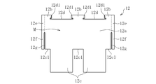
フォイル12は、図2に示すように、本体部Mと、本体部Mの軸方向両側に設けられた接続部12eおよび係止部12fとを有する。フォイルホルダ11に取り付ける前の状態では、フォイル12は同一平面上に設けられる。図3に示すように、フォイル12をフォイルホルダ11の内周面11aに取り付けた状態では、フォイル12の本体部Mはフォイルホルダ11の軸方向領域に設けられ、フォイル12の接続部12e及び係止部12fは、フォイルホルダ11の内周面11aの軸方向両側にはみ出している。フォイルホルダ11に取り付けられた状態で、フォイル12の全域は軸方向と平行である。
As shown in FIG. 2, the foil 12 includes a main body part M, and connection parts 12 e and locking parts 12 f provided on both axial sides of the main body part M. In a state before being attached to the foil holder 11, the foil 12 is provided on the same plane. As shown in FIG. 3, in the state where the foil 12 is attached to the inner peripheral surface 11a of the foil holder 11, the main body portion M of the foil 12 is provided in the axial region of the foil holder 11, and the connection portion 12e of the foil 12 and the engagement portion are connected. The stop portion 12f protrudes to both sides in the axial direction of the inner peripheral surface 11a of the foil holder 11. When attached to the foil holder 11, the entire area of the foil 12 is parallel to the axial direction.
フォイル12の本体部Mは、図2に示すように、トップフォイル部12aと、トップフォイル部12aの下流側(図2の上側)に設けられた差込部12bと、トップフォイル部12aの上流側(図2の下側)に設けられたアンダーフォイル部12cとを有する。
As shown in FIG. 2, the body portion M of the foil 12 includes a top foil portion 12a, an insertion portion 12b provided on the downstream side (upper side in FIG. 2) of the top foil portion 12a, and an upstream side of the top foil portion 12a. And an underfoil portion 12c provided on the side (the lower side in FIG. 2).
トップフォイル部12aの内径側の面は、軸2の外周面2aと対向する軸受面として機能する(図1参照)。本実施形態では、各フォイル12の本体部Mのうち、トップフォイル部12aのみが内周側に露出し、差込部12b及びアンダーフォイル部12cは、他のフォイル12の背後(外径側)に配される。
The surface on the inner diameter side of the top foil portion 12a functions as a bearing surface facing the outer peripheral surface 2a of the shaft 2 (see FIG. 1). In the present embodiment, only the top foil portion 12a of the body portion M of each foil 12 is exposed on the inner peripheral side, and the insertion portion 12b and the underfoil portion 12c are behind the other foils 12 (outer diameter side). Arranged.
差込部12bは、トップフォイル部12aから下流側に延びている。差込部12bとトップフォイル部12aとは周方向で滑らかに連続している。本実施形態では、図2に示すように、差込部12bが、軸方向に離隔した複数箇所(図示例では3箇所)に設けられる。複数の差込部12bの軸方向間には、凹部12dが設けられる。凹部12dの角部には、軸方向の切り込み12d1が設けられる。尚、特に必要がなければ、切り込み12d1を省略してもよい。
The insertion part 12b extends downstream from the top foil part 12a. The insertion part 12b and the top foil part 12a are smoothly continuous in the circumferential direction. In the present embodiment, as shown in FIG. 2, the insertion portions 12b are provided at a plurality of locations (three locations in the illustrated example) spaced apart in the axial direction. A recess 12d is provided between the plurality of insertion portions 12b in the axial direction. An axial cut 12d1 is provided at the corner of the recess 12d. Note that the cut 12d1 may be omitted unless particularly required.
アンダーフォイル部12cは、トップフォイル部12aから上流側に延びている。アンダーフォイル部12cとトップフォイル部12aとは周方向で滑らかに連続している。本実施形態では、アンダーフォイル部12cが、軸方向に離隔した複数箇所(図示例では2箇所)に設けられる。各アンダーフォイル部12cは、凹部12d(切り込み12d1を含む)と同じ軸方向領域に設けられる。複数のアンダーフォイル部12cの軸方向間および軸方向外側には、凹部12c1が設けられる。
The underfoil portion 12c extends upstream from the top foil portion 12a. The underfoil portion 12c and the top foil portion 12a are smoothly continuous in the circumferential direction. In the present embodiment, the underfoil portions 12c are provided at a plurality of locations (two locations in the illustrated example) separated in the axial direction. Each underfoil portion 12c is provided in the same axial region as the recess 12d (including the cut 12d1). Concave portions 12c1 are provided between the axial directions of the plurality of underfoil portions 12c and on the axially outer side.
図1に示すように、各フォイル12のアンダーフォイル部12cは、上流側に隣接するフォイル12のトップフォイル部12aとフォイルホルダ11の内周面11aとの間に配される。これにより、各フォイル12のトップフォイル部12aは、下流側に隣接するフォイル12のアンダーフォイル部12cで背後から支持される。また、隣接するフォイル12のトップフォイル部12aの周方向端部の縁(凹部12dと凹部12c1)は、周方向で係合して互いに突っ張り合っている。これにより、各フォイル12のトップフォイル部12aが外径側に張り出し、フォイルホルダ11の内周面11aに沿った略円筒形状に湾曲する。
As shown in FIG. 1, the underfoil portion 12 c of each foil 12 is disposed between the top foil portion 12 a of the foil 12 adjacent to the upstream side and the inner peripheral surface 11 a of the foil holder 11. Thereby, the top foil part 12a of each foil 12 is supported from the back by the underfoil part 12c of the foil 12 adjacent to the downstream. Further, edges (concave portions 12d and concave portions 12c1) of the end portions in the circumferential direction of the top foil portions 12a of the adjacent foils 12 are engaged with each other in the circumferential direction and stick to each other. Thereby, the top foil part 12a of each foil 12 protrudes to the outer diameter side, and is curved into a substantially cylindrical shape along the inner peripheral surface 11a of the foil holder 11.
図2に示すように、フォイル12は、本体部Mと軸方向で滑らかに連続した接続部12eと、接続部12eと周方向で滑らかに連続した係止部12fとを有する。接続部12eおよび係止部12fは、本体部Mとは異なる軸方向領域に設けられ、図示例では本体部Mの軸方向外側、特に、本体部Mの軸方向両側に設けられる。接続部12eは、例えば、本体部Mの下流側端部を含む領域、具体的には、差込部12b、およびその上流側に連続するトップフォイル部12aの下流側領域と、軸方向に連続している。尚、図2では、本体部Mと接続部12eとの概念的な境界を点線で表している。
As shown in FIG. 2, the foil 12 includes a connecting portion 12e smoothly connected to the main body M in the axial direction, and a locking portion 12f smoothly connected to the connecting portion 12e in the circumferential direction. The connection portion 12e and the locking portion 12f are provided in an axial region different from the main body portion M, and in the illustrated example, are provided on the outer side in the axial direction of the main body portion M, particularly on both sides in the axial direction of the main body portion M. The connecting portion 12e is continuous in the axial direction with, for example, a region including the downstream end portion of the main body M, specifically, the insertion portion 12b and the downstream region of the top foil portion 12a continuous on the upstream side. is doing. In FIG. 2, a conceptual boundary between the main body M and the connecting part 12e is indicated by a dotted line.
係止部12fは、接続部12eを介して本体部Mと接続され、本体部Mとは軸方向で分離されている。図示例では、係止部12fと本体部Mとの軸方向間に、これらを軸方向に分断する周方向のスリット12gが設けられる。図示例の係止部12fは、接続部12eから上流側に延び、その上流側端部は自由端とされる。図示例の係止部12fは、全域がトップフォイル部12aの周方向領域内に設けられる。
The locking portion 12f is connected to the main body portion M through the connection portion 12e, and is separated from the main body portion M in the axial direction. In the illustrated example, a circumferential slit 12g is provided between the locking portion 12f and the main body M in the axial direction to divide them in the axial direction. The locking portion 12f in the illustrated example extends upstream from the connection portion 12e, and its upstream end is a free end. The entire locking portion 12f in the illustrated example is provided in the circumferential region of the top foil portion 12a.
尚、係止部12fの軸方向寸法や周方向寸法を変えることで、係止部12fの強度を調整することができる。係止部12fの軸方向寸法を大きくすると、係止部12fの強度は向上するが、フォイル12全体の軸方向寸法が大きくなる。また、係止部12fの周方向寸法を小さくすると、係止部12fの強度(剛性)は向上するが、フォイルホルダ11との係合領域が小さくなる。これらを考慮して、各部寸法を設定すればよい。
In addition, the intensity | strength of the latching | locking part 12f can be adjusted by changing the axial direction dimension and circumferential direction dimension of the latching | locking part 12f. Increasing the axial dimension of the locking part 12f improves the strength of the locking part 12f, but increases the axial dimension of the foil 12 as a whole. Further, when the circumferential dimension of the locking portion 12f is reduced, the strength (rigidity) of the locking portion 12f is improved, but the engagement area with the foil holder 11 is reduced. The dimensions of each part may be set in consideration of these.
図1に示すように、フォイル12のトップフォイル部12a及びアンダーフォイル部12cは、フォイルホルダ11の内周面11aに沿って略円筒状に湾曲している。また、図4に示すように、フォイル12の接続部12eは、本体部M(トップフォイル部12a)と軸方向で連続しているため、本体部Mに追従して略円筒状に湾曲している。
As shown in FIG. 1, the top foil portion 12 a and the under foil portion 12 c of the foil 12 are curved in a substantially cylindrical shape along the inner peripheral surface 11 a of the foil holder 11. Further, as shown in FIG. 4, the connecting portion 12e of the foil 12 is continuous with the main body portion M (top foil portion 12a) in the axial direction. Yes.
一方、フォイル12の係止部12fは、本体部Mと軸方向で分離されているため、本体部Mに追従して変形しない。また、係止部12fは、フォイルホルダ11の内周面11aよりも軸方向外側に設けられているため、フォイルホルダ11で外径側から拘束されない。従って、係止部12fは、本体部Mやフォイルホルダ11に拘束されず、独立して変形可能とされる。本実施形態では、フォイル12の弾性復元力により、係止部12fが、接続部12eと周方向で滑らかに連続した平板状となり、詳しくは、接続部12eと係止部12fとの境界における接続部12eの略接線方向に延びる平板状となる。これにより、係止部12fが、上流側に行くにつれて、フォイルホルダ11の内周面11aに対して外径側に変位し、その結果、係止部12fがフォイルホルダ11の内周面11aよりも外径側に配される(図1及び図4参照)。これにより、フォイル12の係止部12fとフォイルホルダ11の端面11dとが軸方向で係合可能とされるため、別途の係止部材を設けたり、フォイル12を折り曲げたりすることなく、フォイル12とフォイルホルダ11との軸方向の位置ずれを防止できる。
On the other hand, since the locking portion 12f of the foil 12 is separated from the main body portion M in the axial direction, it does not deform following the main body portion M. Moreover, since the latching | locking part 12f is provided in the axial direction outer side rather than the internal peripheral surface 11a of the foil holder 11, it is not restrained by the foil holder 11 from an outer-diameter side. Accordingly, the locking portion 12f is not restricted by the main body portion M or the foil holder 11, and can be independently deformed. In the present embodiment, due to the elastic restoring force of the foil 12, the locking portion 12f has a flat plate shape that is smoothly continuous with the connecting portion 12e in the circumferential direction, and more specifically, the connection at the boundary between the connecting portion 12e and the locking portion 12f. It becomes flat form extended in the substantially tangential direction of the part 12e. As a result, the engaging portion 12f is displaced to the outer diameter side with respect to the inner peripheral surface 11a of the foil holder 11 as it goes upstream, and as a result, the engaging portion 12f is displaced from the inner peripheral surface 11a of the foil holder 11. Is also arranged on the outer diameter side (see FIGS. 1 and 4). As a result, the engaging portion 12f of the foil 12 and the end surface 11d of the foil holder 11 can be engaged in the axial direction, so that the foil 12 can be provided without providing a separate engaging member or bending the foil 12. And the axial displacement of the foil holder 11 can be prevented.
本実施形態では、図3及び図4では見えていない奥側の係止部12fも、上記と同様の構成を有し、フォイルホルダ11の奥側の端面と軸方向で係合可能とされる。すなわち、フォイル12の軸方向両端に設けられた一対の係止部12fの軸方向間に、フォイルホルダ11を配し、両係止部12fでフォイルホルダ11を軸方向両側から挟持している。これにより、両係止部12fが、フォイルホルダ11に軸方向両側から係合可能となるため、フォイル12のフォイルホルダ11に対する軸方向両側への移動を規制することができる。
In the present embodiment, the rear locking portion 12f that is not visible in FIGS. 3 and 4 also has the same configuration as described above, and can be engaged with the rear end surface of the foil holder 11 in the axial direction. . That is, the foil holder 11 is arranged between the pair of locking portions 12f provided at both ends of the foil 12 in the axial direction, and the foil holder 11 is sandwiched by both locking portions 12f from both sides in the axial direction. Thereby, since both the latching | locking parts 12f can engage with the foil holder 11 from an axial direction both sides, the movement to the axial direction both sides with respect to the foil holder 11 of the foil 12 can be controlled.
以下、フォイル軸受10の組立方法を説明する。
Hereinafter, a method for assembling the foil bearing 10 will be described.
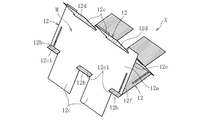
まず、図5に示すように、3枚の平板状のフォイル12を組み合わせて筒状の仮組体Xを形成する。具体的には、隣接するフォイル12のアンダーフォイル部12cと差込部12bとを互いに嵌め合わせる。すなわち、各フォイル12のアンダーフォイル部12cを、隣接するフォイル12の下流側の凹部12dに差し込むと共に、各フォイル12の差込部12bを、隣接するフォイル12の上流側の凹部12c1に差し込む。これにより、3枚のフォイル12が連結され、仮組体Xが形成される。
First, as shown in FIG. 5, a cylindrical temporary assembly X is formed by combining three flat foils 12. Specifically, the underfoil portion 12c and the insertion portion 12b of the adjacent foil 12 are fitted together. That is, the underfoil portion 12 c of each foil 12 is inserted into the recess 12 d on the downstream side of the adjacent foil 12, and the insertion portion 12 b of each foil 12 is inserted into the recess 12 c 1 on the upstream side of the adjacent foil 12. Thereby, the three foils 12 are connected, and the temporary assembly X is formed.
次に、図6に示すように、仮組体Xを円筒状に丸めた状態で、フォイルホルダ11の内周に挿入する。このとき、各フォイル12の係止部12fは、本体部Mに追従して変形しないため、外径側に飛び出す。従って、各フォイル12の軸方向一方側(挿入方向先行側)の係止部12f(図6では見えていない)を、フォイルホルダ11の内周面11aよりも内径側に弾性変形させて、フォイルホルダ11との干渉を回避しながら、仮組体Xをフォイルホルダ11の内周に挿入する。一方、各フォイル12の軸方向他方側の係止部12fは、フォイルホルダ11の内周に挿入されないため、外径側に飛び出したままとされる。この状態で、フォイルホルダ11の端面に開口した溝11cに、各フォイル12の差込部12bを軸方向外側から差し込みながら、フォイルホルダ11の内周に仮組体Xを挿入する。
Next, as shown in FIG. 6, the temporary assembly X is inserted into the inner periphery of the foil holder 11 in a state of being rounded into a cylindrical shape. At this time, the locking portion 12f of each foil 12 does not deform following the main body portion M, and thus jumps out to the outer diameter side. Accordingly, the locking portion 12f (not visible in FIG. 6) on one axial side (the insertion direction leading side) of each foil 12 is elastically deformed to the inner diameter side with respect to the inner peripheral surface 11a of the foil holder 11 so that the foil is The temporary assembly X is inserted into the inner periphery of the foil holder 11 while avoiding interference with the holder 11. On the other hand, since the engaging portion 12f on the other axial side of each foil 12 is not inserted into the inner periphery of the foil holder 11, it is left protruding to the outer diameter side. In this state, the temporary assembly X is inserted into the inner periphery of the foil holder 11 while inserting the insertion portion 12b of each foil 12 into the groove 11c opened from the end surface of the foil holder 11 from the outside in the axial direction.
そして、各フォイル12の軸方向一方側の係止部12fが、フォイルホルダ11の内周面11aを通過して軸方向外側に出たら、軸方向一方側の係止部12fが平板状に弾性復元し、フォイルホルダ11の内周面11aよりも外径側に配される。一方、各フォイル12の軸方向他方側の係止部12fは、フォイルホルダ11の内周面11aよりも外径側に配されたまま、フォイルホルダ11の軸方向他方の端面11dの直近に配される。以上により、各フォイル12の軸方向両側に設けられた一対の係止部12fの軸方向間に、フォイルホルダ11が配される。尚、各係止部12fとフォイルホルダ11の端面11dとは、当接させてもよいし、微小な軸方向隙間を介して対向させてもよい。
And if the latching | locking part 12f of the axial direction one side of each foil 12 passes the inner peripheral surface 11a of the foil holder 11, and will come out to an axial direction outer side, the locking part 12f of the axial direction one side will be elastically flat. It restores and is arranged on the outer diameter side from the inner peripheral surface 11a of the foil holder 11. On the other hand, the locking portion 12f on the other axial side of each foil 12 is arranged in the immediate vicinity of the other end surface 11d in the axial direction of the foil holder 11 while being arranged on the outer diameter side of the inner peripheral surface 11a of the foil holder 11. Is done. As described above, the foil holder 11 is disposed between the axial directions of the pair of locking portions 12f provided on both axial sides of each foil 12. In addition, each latching | locking part 12f and the end surface 11d of the foil holder 11 may be contact | abutted, and may be made to oppose via a micro axial direction clearance gap.
このように、本実施形態では、フォイル12に、本体部Mと軸方向で分離され、本体部Mから独立して半径方向に変形可能な係止部12fを設け、この係止部12fを、フォイルホルダ11の内周面11aから軸方向外側にはみ出させて、フォイルホルダ11で外径側から拘束されない位置に配した。これにより、フォイル12をフォイルホルダ11の内周面11aに取り付けるだけで、係止部12fの弾性復元力により、係止部12fをフォイルホルダ11の内周面11aの外径側に配することができる。
Thus, in this embodiment, the foil 12 is provided with a locking portion 12f that is separated from the main body portion M in the axial direction and can be deformed in the radial direction independently of the main body portion M. The foil holder 11 protrudes outward in the axial direction from the inner peripheral surface 11 a and is arranged at a position where the foil holder 11 is not restrained from the outer diameter side. Thereby, only by attaching the foil 12 to the inner peripheral surface 11a of the foil holder 11, the engaging portion 12f is arranged on the outer diameter side of the inner peripheral surface 11a of the foil holder 11 by the elastic restoring force of the engaging portion 12f. Can do.
軸2が図1の矢印方向に回転すると、フォイル軸受10の各フォイル12のトップフォイル部12aの内径面(軸受面)と軸2の外周面2aとの間に軸受隙間Rが形成される。このとき、各フォイル12のトップフォイル部12aは、下流側に隣接するフォイル12のアンダーフォイル部12cの上に乗り上げている。また、各フォイル12の下流側端部に設けられた差込部12bは、フォイルホルダ11の溝11cに差し込まれ、これによりトップフォイル部12aの下流端近傍が、トップフォイル部12a全体の湾曲方向(フォイルホルダ11の内周面11aの湾曲方向)と逆向き、すなわち内径側に凸となるように湾曲しようとする。以上により、下流側に向けて隙間幅が徐々に狭くなった楔状の軸受隙間Rが形成され、この楔状の軸受隙間Rの幅狭側に空気が押し込まれることにより、軸受隙間Rの空気膜の圧力が高められ、この圧力により軸2がラジアル方向に非接触支持される。尚、図1では、軸受隙間Rの幅を誇張して示している。
When the shaft 2 rotates in the direction of the arrow in FIG. 1, a bearing gap R is formed between the inner diameter surface (bearing surface) of the top foil portion 12 a of each foil 12 of the foil bearing 10 and the outer peripheral surface 2 a of the shaft 2. At this time, the top foil part 12a of each foil 12 rides on the underfoil part 12c of the foil 12 adjacent to the downstream side. Moreover, the insertion part 12b provided in the downstream edge part of each foil 12 is inserted in the groove | channel 11c of the foil holder 11, Thereby, the downstream end vicinity of the top foil part 12a is the curve direction of the top foil part 12a whole. It tends to bend in a direction opposite to the bending direction of the inner peripheral surface 11a of the foil holder 11, that is, convex toward the inner diameter side. As described above, the wedge-shaped bearing gap R having the gap width gradually narrowed toward the downstream side is formed, and air is pushed into the narrow side of the wedge-shaped bearing gap R, so that the air film of the bearing gap R is reduced. The pressure is increased, and the shaft 2 is supported in a non-contact manner in the radial direction by this pressure. In FIG. 1, the width of the bearing gap R is exaggerated.
上記のように、各フォイル12のトップフォイル部12aが他のフォイル12のアンダーフォイル部12cに乗り上げ、且つ、トップフォイル部12aの下流端近傍が内径側に凸となるように湾曲することで、トップフォイル部12aに半径方向のバネ性が付与される。これにより、各フォイル12のトップフォイル部12aの軸受面が、荷重や軸2の回転速度、周囲温度等の運転条件に応じて任意に変形するため、軸受隙間Rは運転条件に応じた適切幅に自動調整される。そのため、高温・高速回転といった過酷な条件下でも、軸受隙間を最適幅に管理することができ、軸2を安定して支持することが可能となる。
As described above, the top foil portion 12a of each foil 12 rides on the underfoil portion 12c of the other foil 12, and the vicinity of the downstream end of the top foil portion 12a is curved so as to protrude toward the inner diameter side. A spring property in the radial direction is imparted to the top foil portion 12a. As a result, the bearing surface of the top foil portion 12a of each foil 12 is arbitrarily deformed according to the operating conditions such as the load, the rotational speed of the shaft 2, the ambient temperature, etc., so the bearing gap R has an appropriate width according to the operating conditions. Automatically adjusted. Therefore, the bearing gap can be managed to the optimum width even under severe conditions such as high temperature and high speed rotation, and the shaft 2 can be stably supported.
また、各フォイル12は、フォイルホルダ11に完全に固定されておらず、フォイルホルダ11に対して微小移動可能とされる。従って、軸2の回転中は、軸受隙間に形成された空気膜の影響でフォイル12がフォイルホルダ11に押し付けられ、これに伴って各フォイル12とフォイルホルダ11、特に、各フォイル12のアンダーフォイル部12cの外径面とフォイルホルダ11の内周面11aとの間や、各フォイル12の差込部12bとフォイルホルダ11の溝11cとの間に微小摺動が生じる。この微小摺動による摩擦エネルギーにより、軸2の振動を減衰させることができる。
Further, each foil 12 is not completely fixed to the foil holder 11 and can be moved minutely with respect to the foil holder 11. Therefore, while the shaft 2 is rotating, the foil 12 is pressed against the foil holder 11 due to the influence of the air film formed in the bearing gap, and accordingly, the foil 12 and the foil holder 11, particularly the underfoil of each foil 12, are pressed. Minute sliding occurs between the outer diameter surface of the portion 12 c and the inner peripheral surface 11 a of the foil holder 11, or between the insertion portion 12 b of each foil 12 and the groove 11 c of the foil holder 11. The vibration of the shaft 2 can be attenuated by the frictional energy generated by the minute sliding.
尚、軸2の停止直前や起動直後の低速回転時には、各フォイル12の軸受面と軸2の外周面とが接触摺動する。このとき、各フォイル12の軸受面に、PTFE、DLC、チタンアルミナイトライド等からなる被膜を設ければ、軸受面の摩耗を防止することができる。また、フォイル12とフォイルホルダ11との間の微小摺動による摩擦力を調整するために、これらの何れか一方または双方に、上記のような被膜を形成してもよい。また、フォイル12やフォイルホルダ11に設ける被膜として、上記の他、二硫化タングステン膜や二硫化モリブデン膜を用いてもよい。
Note that the bearing surface of each foil 12 and the outer peripheral surface of the shaft 2 slide in contact with each other at the time of low-speed rotation immediately before the shaft 2 stops or immediately after the shaft 2 starts. At this time, if a coating made of PTFE, DLC, titanium aluminum nitride, or the like is provided on the bearing surface of each foil 12, the bearing surface can be prevented from being worn. Moreover, in order to adjust the frictional force caused by the minute sliding between the foil 12 and the foil holder 11, the above-described coating may be formed on one or both of them. In addition to the above, a tungsten disulfide film or a molybdenum disulfide film may be used as a film provided on the foil 12 or the foil holder 11.
本発明は上記の実施形態に限られない。以下、本発明の他の実施形態について説明するが、上記の実施形態と重複する点は説明を省略する。
The present invention is not limited to the above embodiment. Hereinafter, although other embodiment of this invention is described, description which abbreviate | omits the said embodiment is abbreviate | omitted.
図7に示す第二実施形態では、スリット12gの下流側端部に軸方向幅の広い領域12g1を設けている。この場合、スリット12gの下流側端部における応力集中が緩和され、フォイル12の損傷が防止できる。
In the second embodiment shown in FIG. 7, a region 12g1 having a wide axial width is provided at the downstream end of the slit 12g. In this case, stress concentration at the downstream end of the slit 12g is alleviated, and damage to the foil 12 can be prevented.
図8に示す第三実施形態では、各フォイル12の係止部12fが、接続部12eから下流側に延び、下流側端部が自由端となっている点で、上記の実施形態と異なる。この係止部12fは、本体部Mよりも下流側に設けられている。具体的には、各フォイル12の差込部12bの軸方向外側に連続して接続部12eが設けられ、この接続部12eの下流側に連続して係止部12fが延びている。このフォイル12をフォイルホルダ11の内周面11aに取り付けると、図9に示すように、係止部12fが、接続部12eの延長線上に延び、フォイルホルダ11の内周面11aよりも外径側に配される。
8 differs from the above embodiment in that the locking portion 12f of each foil 12 extends downstream from the connecting portion 12e, and the downstream end is a free end. The locking portion 12f is provided on the downstream side of the main body portion M. Specifically, a connecting portion 12e is provided continuously outside the insertion portion 12b of each foil 12 in the axial direction, and a locking portion 12f extends continuously downstream of the connecting portion 12e. When the foil 12 is attached to the inner peripheral surface 11a of the foil holder 11, as shown in FIG. 9, the locking portion 12f extends on the extension line of the connecting portion 12e, and the outer diameter is larger than the inner peripheral surface 11a of the foil holder 11. Arranged on the side.
以上の実施形態では、各フォイル12の本体部Mの下流側端部に接続部12eを接続しているが、これに限らず、本体部Mの上流側端部や周方向中間部に接続部12eを接続してもよい。
In the above embodiment, the connection part 12e is connected to the downstream end of the main body part M of each foil 12, but the connection part is not limited to this, and is connected to the upstream end part or the circumferential intermediate part of the main body part M. 12e may be connected.
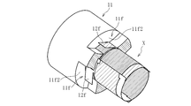
また、図10に示す第四実施形態では、フォイルホルダ11の内周面11aの軸方向端部に、凹部11eを設けている。図示例の凹部11eは、全周に連続して設けられる。凹部11eの軸方向寸法は、フォイル12の接続部12eおよび係止部12fの軸方向寸法よりも僅かに大きい。この凹部11eの軸方向領域に、フォイル12の接続部12eおよび係止部12fが収容される(図11参照)。これにより、フォイル12の接続部12eおよび係止部12fがフォイルホルダ11から軸方向外側に突出しないため、フォイル軸受10をターボ機械等に組み込む際に、フォイル12の接続部12eおよび係止部12fがターボ機械のハウジング等に接触して損傷する事態を防止できる。フォイル12の係止部12fは、フォイルホルダ11の凹部11eに形成された端面11e1(肩面)と軸方向で係合可能とされる。
Further, in the fourth embodiment shown in FIG. 10, a recess 11 e is provided at the axial end of the inner peripheral surface 11 a of the foil holder 11. The recess 11e in the illustrated example is continuously provided on the entire circumference. The axial dimension of the recess 11e is slightly larger than the axial dimension of the connection part 12e and the locking part 12f of the foil 12. The connecting portion 12e and the locking portion 12f of the foil 12 are accommodated in the axial direction region of the recess 11e (see FIG. 11). Thereby, since the connection part 12e and the latching | locking part 12f of the foil 12 do not protrude to the axial direction outer side from the foil holder 11, when incorporating the foil bearing 10 in a turbomachine etc., the connection part 12e and the latching | locking part 12f of the foil 12 Can be prevented from being damaged by contact with the housing of the turbomachine. The locking portion 12f of the foil 12 can be engaged with an end surface 11e1 (shoulder surface) formed in the concave portion 11e of the foil holder 11 in the axial direction.
フォイルホルダ11の内周面の凹部11eは、必ずしも全周に形成する必要はない。例えば、図12及び図13に示す第五実施形態のように、周方向に離隔した複数箇所に凹部11eを設けてもよい。各凹部11eの軸方向領域に、各フォイル12の係止部12fが収容される。尚、上記の第四及び第五実施形態において、フォイル12の係止部12fは、フォイルホルダ11の凹部11eの底面(軸方向と平行な面)から離反させて平板状に延ばしてもよいし、凹部11eの底面に接触させて係止部12fを内径側に湾曲させてもよい。
The recess 11e on the inner peripheral surface of the foil holder 11 is not necessarily formed on the entire periphery. For example, as in the fifth embodiment shown in FIGS. 12 and 13, the recesses 11e may be provided at a plurality of locations separated in the circumferential direction. The locking portion 12f of each foil 12 is accommodated in the axial region of each recess 11e. In addition, in said 4th and 5th embodiment, the latching | locking part 12f of the foil 12 may be separated from the bottom face (surface parallel to an axial direction) of the recessed part 11e of the foil holder 11, and may be extended in flat form. The locking portion 12f may be curved toward the inner diameter side by contacting the bottom surface of the recess 11e.
以上の実施形態では、フォイル12の本体部Mの軸方向両側に係止部12f及び接続部12eを設けた場合を示したが、特に必要がなければ何れかの係止部12f及び接続部12eを省略し、フォイル12の本体部Mの軸方向一方側のみに係止部12f及び接続部12eを設けてもよい。
In the above embodiment, the case where the locking portions 12f and the connection portions 12e are provided on both sides in the axial direction of the main body portion M of the foil 12 has been described. If there is no particular need, any of the locking portions 12f and the connection portions 12e. May be omitted, and the locking portion 12f and the connecting portion 12e may be provided only on one side in the axial direction of the body portion M of the foil 12.
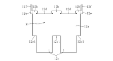
図14に示す第六実施形態は、フォイル12の接続部12e及び係止部12fが、フォイル12の軸方向中間部(図示例では軸方向中央部)に設けられている点で、上記の実施形態と異なる。具体的に、接続部12eの軸方向両側に、それぞれ本体部Mが連続して設けられている。図示例では、接続部12eが、各本体部Mのトップフォイル部12a、特にトップフォイル部12aの下流側端部を含む領域と軸方向で連続している。係止部12fは、接続部12eから上流側に延びている。係止部12fと各本体部Mとの間には、それぞれスリット12gが設けられる。
In the sixth embodiment shown in FIG. 14, the connecting portion 12e and the locking portion 12f of the foil 12 are provided in the axially intermediate portion of the foil 12 (in the illustrated example, the axially central portion). Different from form. Specifically, the main body portions M are continuously provided on both sides in the axial direction of the connecting portion 12e. In the example of illustration, the connection part 12e is following the area | region including the downstream end part of the top foil part 12a of each main-body part M, especially the top foil part 12a in the axial direction. The locking portion 12f extends upstream from the connection portion 12e. Between the latching | locking part 12f and each main-body part M, the slit 12g is each provided.
上記のフォイル12は、図15に示すフォイルホルダ11に取り付けられる。このフォイルホルダ11の内周面11aの軸方向中間部に凹部が設けられる。本実施形態では、図16の断面図に示すように、フォイルホルダ11の軸方向中間部(図示例では軸方向中央部)に、凹部として、フォイルホルダ11の内周面11aおよび外周面11bに開口した貫通孔11fが設けられる。貫通孔11fは、フォイル12の係止部12fと同じ数だけ設けられ、図示例では、周方向等間隔の3箇所に設けられる。各貫通孔11fの周方向両側の側壁11f1は、軸方向と平行な凹曲面である。図示例では、各貫通孔11fの周方向両側の側壁11f1が、同一円筒面上に設けられる。
The foil 12 is attached to the foil holder 11 shown in FIG. A concave portion is provided in the axially intermediate portion of the inner peripheral surface 11 a of the foil holder 11. In the present embodiment, as shown in the cross-sectional view of FIG. 16, the concave portion is formed on the inner peripheral surface 11 a and the outer peripheral surface 11 b of the foil holder 11 as a concave portion in the axial direction intermediate portion (axial central portion in the illustrated example). An open through-hole 11f is provided. The same number of through holes 11f as the locking portions 12f of the foil 12 are provided, and in the illustrated example, the through holes 11f are provided at three locations at equal intervals in the circumferential direction. Side walls 11f1 on both sides in the circumferential direction of each through hole 11f are concave curved surfaces parallel to the axial direction. In the illustrated example, side walls 11f1 on both sides in the circumferential direction of each through hole 11f are provided on the same cylindrical surface.
本実施形態のフォイル軸受10は、第一実施形態とおおよそ同様の手順で組み立てられる。具体的には、まず、図17に示すように、3枚のフォイル12のアンダーフォイル部12cと差込部12bとを互いに嵌め合わせ、筒状の仮組体Xを形成する。
The foil bearing 10 of the present embodiment is assembled in the same procedure as that of the first embodiment. Specifically, first, as shown in FIG. 17, the underfoil portion 12c and the insertion portion 12b of the three foils 12 are fitted together to form a cylindrical temporary assembly X.
次に、図18に示すように、仮組体Xを円筒状に丸めた状態で、フォイルホルダ11の内周に挿入する。このとき、円筒状に丸めた仮組体Xから外径側に飛び出した係止部12fを、フォイルホルダ11の内周面11aよりも内径側に弾性変形させながら、仮組体Xをフォイルホルダ11の内周に挿入する。そして、係止部12fが、フォイルホルダ11の軸方向中央部の貫通孔11fに嵌まり込むと、図19及び図20に示すように、係止部12fが平板状に弾性復元し、フォイルホルダ11の内周面11aよりも外径側に配される。以上により、フォイルホルダ11の貫通孔11fにフォイル12の係止部12fが収容され、貫通孔11fの軸方向両側の側壁11f2(図19及び図20では、軸方向一方の側壁11f2のみを示している。)の軸方向間に係止部12fが配される。これにより、係止部12fが、貫通孔11fの軸方向両側の側壁11f2と係合可能とされ、フォイル12のフォイルホルダ11からの軸方向の抜け止めが行われる。
Next, as shown in FIG. 18, the temporary assembly X is inserted into the inner circumference of the foil holder 11 in a state of being rounded into a cylindrical shape. At this time, the temporary assembly X is removed from the foil holder 11 while elastically deforming the locking portion 12f that protrudes from the cylindrical assembly X to the outer diameter side toward the inner diameter side of the inner peripheral surface 11a of the foil holder 11. 11 is inserted into the inner periphery. Then, when the locking portion 12f is fitted into the through hole 11f in the central portion in the axial direction of the foil holder 11, the locking portion 12f is elastically restored to a flat plate shape as shown in FIGS. 19 and 20, and the foil holder 11 is arranged closer to the outer diameter side than the inner peripheral surface 11a. Thus, the engaging portion 12f of the foil 12 is accommodated in the through hole 11f of the foil holder 11, and the side walls 11f2 on both sides in the axial direction of the through hole 11f (in FIGS. 19 and 20, only one side wall 11f2 in the axial direction is shown). The locking portion 12f is disposed between the axial directions. As a result, the locking portion 12f can be engaged with the side walls 11f2 on both axial sides of the through hole 11f, and the foil 12 is prevented from coming off from the foil holder 11 in the axial direction.
軸2が図20の矢印P方向に回転すると、フォイル軸受10の各フォイル12のトップフォイル部12aの内径面(軸受面)と軸2の外周面2aとの間に軸受隙間Rが形成される。このとき、接続部12eの軸方向両側に本体部Mを設けることで、軸受面(トップフォイル部12a)が軸方向に離隔した2箇所に形成される。このように、軸受面が明確に複列化されることで、フォイル軸受10のモーメント剛性が増大する。
When the shaft 2 rotates in the direction of arrow P in FIG. 20, a bearing gap R is formed between the inner diameter surface (bearing surface) of the top foil portion 12 a of each foil 12 of the foil bearing 10 and the outer peripheral surface 2 a of the shaft 2. . At this time, by providing the main body part M on both axial sides of the connecting part 12e, the bearing surface (top foil part 12a) is formed at two locations separated in the axial direction. Thus, the moment rigidity of the foil bearing 10 increases because the bearing surfaces are clearly doubled.
また、軸受隙間Rの流体(空気)が軸2の回転方向に流動することで、図20に矢印Q方向で示すように、貫通孔11fを介して、外部の空気がフォイルホルダ11の内周、特に軸受隙間Rに流入する。これにより、軸受隙間Rの空気量が増大し、軸受隙間Rにおける空気膜の圧力がさらに高められるため、フォイル軸受10の負荷容量が高められる。また、軸受隙間Rに外部の空気が流入することで、軸受面(トップフォイル部12a)を冷却することができる。特に、図20では、フォイルホルダ11の貫通孔11fの周方向両側の側壁11f1が、軸方向と平行な凹曲面である。これにより、例えば図21に示すように、フォイルホルダ11の貫通孔11fの周方向両側の側壁11f1が平坦面である場合と比べて、軸2の回転時に貫通孔11fを介して外部の空気が軸受隙間Rに流入しやすいため、軸受剛性の向上や軸受面の冷却効果が得られやすい。尚、フォイルホルダ11の外周面が取り付けられるハウジングに、上記の貫通孔11fと外部とを連通する連通路(貫通孔等)を設ければ、外部の空気が軸受隙間Rにさらに流入しやすくなる。
Further, as the fluid (air) in the bearing gap R flows in the rotation direction of the shaft 2, as shown by the arrow Q direction in FIG. In particular, it flows into the bearing gap R. As a result, the amount of air in the bearing gap R increases and the pressure of the air film in the bearing gap R is further increased, so that the load capacity of the foil bearing 10 is increased. Further, the outside air flows into the bearing gap R, so that the bearing surface (top foil portion 12a) can be cooled. In particular, in FIG. 20, the side walls 11f1 on both sides in the circumferential direction of the through hole 11f of the foil holder 11 are concave curved surfaces parallel to the axial direction. As a result, for example, as shown in FIG. 21, compared with the case where the side walls 11f1 on both sides in the circumferential direction of the through-hole 11f of the foil holder 11 are flat surfaces, the external air is passed through the through-hole 11f when the shaft 2 is rotated. Since it tends to flow into the bearing gap R, it is easy to improve the bearing rigidity and cool the bearing surface. In addition, if the communication path (through-hole etc.) which connects said through-hole 11f and the exterior is provided in the housing to which the outer peripheral surface of the foil holder 11 is attached, external air will more easily flow into the bearing gap R. .
尚、係止部12f及び貫通孔11fの周方向位置、軸方向位置、及び数は上記に限らず、これらを増減させてもよい。
In addition, the circumferential position, the axial position, and the number of the locking portion 12f and the through hole 11f are not limited to the above, and may be increased or decreased.
本発明が適用されるフォイル軸受は上記に限られない。例えば、軸受面を有するトップフォイルと、トップフォイルを背後から弾性的に支持するバックフォイルとを有するバンプ型のフォイル軸受に、本発明を適用してもよい。この場合、本発明の特徴的構成である係止部及び接続部を有するフォイルを、トップフォイルとしてもよいし、バックフォイルとしてもよい。
The foil bearing to which the present invention is applied is not limited to the above. For example, the present invention may be applied to a bump-type foil bearing having a top foil having a bearing surface and a back foil that elastically supports the top foil from behind. In this case, the foil having the locking portion and the connecting portion, which is a characteristic configuration of the present invention, may be a top foil or a back foil.
また、以上の実施形態では、フォイル軸受10を固定し、軸2を回転させた場合を示したが、これに限らず、軸2を固定し、フォイル軸受10を回転させてもよい。ただし、フォイル軸受10を回転させると、遠心力でフォイル12が破損する恐れがあるため、フォイル軸受10は固定することが好ましい。
In the above embodiment, the case where the foil bearing 10 is fixed and the shaft 2 is rotated is shown. However, the present invention is not limited to this, and the foil bearing 10 may be rotated while the shaft 2 is fixed. However, if the foil bearing 10 is rotated, the foil 12 may be damaged by centrifugal force. Therefore, the foil bearing 10 is preferably fixed.
また、以上に示したフォイル軸受10は、ガスタービンやターボチャージャ(過給機)等のターボ機械の他、自動車等の車両用軸受、あるいは産業機器用の軸受等として使用することが可能である。
The foil bearing 10 shown above can be used as a bearing for a vehicle such as an automobile or a bearing for industrial equipment, in addition to a turbo machine such as a gas turbine or a turbocharger (supercharger). .
また、以上に述べたフォイル軸受は、圧力発生流体として空気を使用した空気動圧軸受のみならず、圧力発生流体として潤滑油を使用した油動圧軸受としても使用することができる。
Further, the foil bearing described above can be used not only as an air dynamic pressure bearing using air as a pressure generating fluid but also as an oil dynamic pressure bearing using lubricating oil as a pressure generating fluid.
2 軸
10 フォイル軸受
11 フォイルホルダ
11e 凹部
11f 貫通孔(凹部)
12 フォイル
12a トップフォイル部
12b 差込部
12c アンダーフォイル部
12e 接続部
12f 係止部
M 本体部
R 軸受隙間
X 仮組体 2shaft 10 foil bearing 11 foil holder 11e recess 11f through hole (recess)
12Foil 12a Top foil part 12b Insertion part 12c Underfoil part 12e Connection part 12f Locking part M Body part R Bearing gap X Temporary assembly
10 フォイル軸受
11 フォイルホルダ
11e 凹部
11f 貫通孔(凹部)
12 フォイル
12a トップフォイル部
12b 差込部
12c アンダーフォイル部
12e 接続部
12f 係止部
M 本体部
R 軸受隙間
X 仮組体 2
12
Claims (11)
- 筒状のフォイルホルダと、前記フォイルホルダの内周面に取り付けられたフォイルとを備え、内周に挿入された軸を相対回転自在に支持するフォイル軸受であって、
前記フォイルが、前記フォイルホルダの内周面に沿って湾曲した本体部と、前記本体部と軸方向で連続し、前記本体部と同様に湾曲した接続部と、前記接続部と周方向で連続し、前記フォイルホルダの内周面よりも外径側に配され、前記フォイルホルダと軸方向で係合可能な係止部とを備えたフォイル軸受。 A foil bearing comprising a tubular foil holder and a foil attached to the inner peripheral surface of the foil holder, and supporting a shaft inserted in the inner periphery so as to be relatively rotatable,
The foil is continuous along the inner peripheral surface of the foil holder, the main body portion is continuous with the main body portion in the axial direction, and the connection portion is curved similarly to the main body portion, and is continuous with the connection portion in the circumferential direction. And the foil bearing provided with the latching | locking part which was distribute | arranged to the outer diameter side rather than the internal peripheral surface of the said foil holder, and can be engaged with the said foil holder in an axial direction. - 前記係止部が、前記接続部と滑らかに連続した請求項1に記載のフォイル軸受。 The foil bearing according to claim 1, wherein the locking portion is smoothly continuous with the connecting portion.
- 前記係止部が前記フォイルの軸方向両端に設けられ、両係止部の軸方向間に前記フォイルホルダを配した請求項1又は2に記載のフォイル軸受。 The foil bearing according to claim 1 or 2, wherein the locking portions are provided at both axial ends of the foil, and the foil holder is disposed between the axial directions of both locking portions.
- 前記フォイルホルダの内周面の軸方向端部に凹部を設け、該凹部の軸方向領域に前記フォイルの係止部を収容した請求項1~3の何れか1項に記載のフォイル軸受。 The foil bearing according to any one of claims 1 to 3, wherein a concave portion is provided at an axial end portion of the inner peripheral surface of the foil holder, and a locking portion of the foil is accommodated in an axial region of the concave portion.
- 前記フォイルホルダの内周面の軸方向中間部に凹部を設け、前記凹部の軸方向両側の側壁の間に前記フォイルの係止部を配した請求項1又は2に記載のフォイル軸受。 The foil bearing according to claim 1 or 2, wherein a concave portion is provided in an axially intermediate portion of the inner peripheral surface of the foil holder, and a locking portion of the foil is arranged between side walls on both axial sides of the concave portion.
- 前記凹部が、半径方向の貫通孔で構成された請求項5に記載のフォイル軸受。 The foil bearing according to claim 5, wherein the concave portion is configured by a radial through hole.
- 前記貫通孔の周方向両側の側壁が、軸方向と平行な凹曲面である請求項6に記載のフォイル軸受。 The foil bearing according to claim 6, wherein side walls on both sides in the circumferential direction of the through hole are concave curved surfaces parallel to the axial direction.
- 前記フォイルの前記本体部に、前記軸の外周面と対向する軸受面が設けられた請求項1~7の何れか1項に記載のフォイル軸受。 The foil bearing according to any one of claims 1 to 7, wherein a bearing surface facing the outer peripheral surface of the shaft is provided on the main body portion of the foil.
- 前記フォイルの前記本体部が、前記接続部の軸方向両側に設けられた請求項8に記載のフォイル軸受。 The foil bearing according to claim 8, wherein the main body portion of the foil is provided on both axial sides of the connection portion.
- 軸受面を有するトップフォイルをさらに有し、前記フォイルが、前記トップフォイルを背後から支持するバックフォイルである請求項1~7の何れか1項に記載のフォイル軸受。 The foil bearing according to any one of claims 1 to 7, further comprising a top foil having a bearing surface, wherein the foil is a back foil that supports the top foil from behind.
- 筒状のフォイルホルダの内周面に取り付けられ、フォイル軸受を構成するフォイルであって、
前記フォイルホルダの内周面に沿って湾曲した本体部と、前記本体部と前記フォイルホルダの軸方向で連続し、前記本体部と同様に湾曲した接続部と、前記接続部と前記フォイルホルダの周方向で連続し、前記フォイルホルダの内周面よりも外径側に配され、前記フォイルホルダと軸方向で係合可能な係止部とを備えたフォイル。 A foil that is attached to the inner peripheral surface of the tubular foil holder and constitutes a foil bearing,
A main body that is curved along an inner peripheral surface of the foil holder, a connecting portion that is continuous in the axial direction of the main body and the foil holder, and is curved in the same manner as the main body, and the connecting portion and the foil holder. A foil comprising a locking portion that is continuous in the circumferential direction, is disposed on the outer diameter side of the inner circumferential surface of the foil holder, and is engageable with the foil holder in the axial direction.
Applications Claiming Priority (4)
| Application Number | Priority Date | Filing Date | Title |
|---|---|---|---|
| JP2016069016 | 2016-03-30 | ||
| JP2016-069016 | 2016-03-30 | ||
| JP2016-195736 | 2016-10-03 | ||
| JP2016195736A JP2017187166A (en) | 2016-03-30 | 2016-10-03 | Foil bearing |
Publications (1)
| Publication Number | Publication Date |
|---|---|
| WO2017169676A1 true WO2017169676A1 (en) | 2017-10-05 |
Family
ID=59964210
Family Applications (1)
| Application Number | Title | Priority Date | Filing Date |
|---|---|---|---|
| PCT/JP2017/009866 WO2017169676A1 (en) | 2016-03-30 | 2017-03-13 | Foil bearing |
Country Status (1)
| Country | Link |
|---|---|
| WO (1) | WO2017169676A1 (en) |
Cited By (1)
| Publication number | Priority date | Publication date | Assignee | Title |
|---|---|---|---|---|
| JP2022540995A (en) * | 2019-07-16 | 2022-09-21 | ロベルト・ボッシュ・ゲゼルシャフト・ミト・ベシュレンクテル・ハフツング | foil bearing |
Citations (5)
| Publication number | Priority date | Publication date | Assignee | Title |
|---|---|---|---|---|
| JP2008261496A (en) * | 2007-04-12 | 2008-10-30 | Hamilton Sundstrand Corp | Hydrodynamic fluid film journal bearing assembly and its manufacturing method |
| JP2011144846A (en) * | 2010-01-13 | 2011-07-28 | Shimadzu Corp | Dynamic pressure gas bearing |
| WO2013042713A1 (en) * | 2011-09-22 | 2013-03-28 | Ntn株式会社 | Foil bearing |
| WO2014014036A1 (en) * | 2012-07-18 | 2014-01-23 | 株式会社Ihi | Radial foil bearing |
| WO2015026655A1 (en) * | 2013-08-20 | 2015-02-26 | Borgwarner Inc. | Air bearing arrangement |
-
2017
- 2017-03-13 WO PCT/JP2017/009866 patent/WO2017169676A1/en active Application Filing
Patent Citations (5)
| Publication number | Priority date | Publication date | Assignee | Title |
|---|---|---|---|---|
| JP2008261496A (en) * | 2007-04-12 | 2008-10-30 | Hamilton Sundstrand Corp | Hydrodynamic fluid film journal bearing assembly and its manufacturing method |
| JP2011144846A (en) * | 2010-01-13 | 2011-07-28 | Shimadzu Corp | Dynamic pressure gas bearing |
| WO2013042713A1 (en) * | 2011-09-22 | 2013-03-28 | Ntn株式会社 | Foil bearing |
| WO2014014036A1 (en) * | 2012-07-18 | 2014-01-23 | 株式会社Ihi | Radial foil bearing |
| WO2015026655A1 (en) * | 2013-08-20 | 2015-02-26 | Borgwarner Inc. | Air bearing arrangement |
Cited By (1)
| Publication number | Priority date | Publication date | Assignee | Title |
|---|---|---|---|---|
| JP2022540995A (en) * | 2019-07-16 | 2022-09-21 | ロベルト・ボッシュ・ゲゼルシャフト・ミト・ベシュレンクテル・ハフツング | foil bearing |
Similar Documents
| Publication | Publication Date | Title |
|---|---|---|
| JP6479456B2 (en) | Foil, foil bearing, and method of assembling foil bearing | |
| WO2015087675A1 (en) | Foil bearing, and foil bearing unit and turbo machine each having same | |
| US8414191B2 (en) | Keyless/grooveless foil bearing with fold over tab | |
| WO2018051867A1 (en) | Mechanical seal | |
| EP2818738A1 (en) | Tilting pad bearing | |
| WO2013042713A1 (en) | Foil bearing | |
| JP2017187166A (en) | Foil bearing | |
| JP6104597B2 (en) | Foil bearing | |
| WO2017086190A1 (en) | Foil bearing | |
| WO2018016268A1 (en) | Foil bearing | |
| JP6615573B2 (en) | Thrust foil bearing | |
| WO2017169676A1 (en) | Foil bearing | |
| CN108350934B (en) | Foil bearing, method for manufacturing same, and intermediate product of foil bearing | |
| WO2019017134A1 (en) | Foil bearing | |
| JP2012072817A (en) | Foil bearing | |
| JP6629042B2 (en) | Foil bearing | |
| JP6541946B2 (en) | Foil bearing and foil provided thereto | |
| JP2017172764A (en) | Foil bearing | |
| JP6693945B2 (en) | Foil bearing and foil bearing device | |
| JP2020041589A (en) | Foil bearing | |
| JP6654081B2 (en) | Foil bearing | |
| WO2017051658A1 (en) | Foil bearing and manufacturing method therefor | |
| JP6440999B2 (en) | Foil bearing and foil provided on the same | |
| WO2016031465A1 (en) | Foil bearing and foil disposed in same | |
| JP6324774B2 (en) | Foil bearing and turbomachine equipped with the same |
Legal Events
| Date | Code | Title | Description |
|---|---|---|---|
| NENP | Non-entry into the national phase |
Ref country code: DE |
|
| 121 | Ep: the epo has been informed by wipo that ep was designated in this application |
Ref document number: 17774220 Country of ref document: EP Kind code of ref document: A1 |
|
| 122 | Ep: pct application non-entry in european phase |
Ref document number: 17774220 Country of ref document: EP Kind code of ref document: A1 |