WO2017169642A1 - 容量可変型斜板式圧縮機 - Google Patents
容量可変型斜板式圧縮機 Download PDFInfo
- Publication number
- WO2017169642A1 WO2017169642A1 PCT/JP2017/009603 JP2017009603W WO2017169642A1 WO 2017169642 A1 WO2017169642 A1 WO 2017169642A1 JP 2017009603 W JP2017009603 W JP 2017009603W WO 2017169642 A1 WO2017169642 A1 WO 2017169642A1
- Authority
- WO
- WIPO (PCT)
- Prior art keywords
- chamber
- swash plate
- discharge
- suction
- valve
- Prior art date
- Legal status (The legal status is an assumption and is not a legal conclusion. Google has not performed a legal analysis and makes no representation as to the accuracy of the status listed.)
- Ceased
Links
Images






Classifications
-
- F—MECHANICAL ENGINEERING; LIGHTING; HEATING; WEAPONS; BLASTING
- F04—POSITIVE - DISPLACEMENT MACHINES FOR LIQUIDS; PUMPS FOR LIQUIDS OR ELASTIC FLUIDS
- F04B—POSITIVE-DISPLACEMENT MACHINES FOR LIQUIDS; PUMPS
- F04B27/00—Multi-cylinder pumps specially adapted for elastic fluids and characterised by number or arrangement of cylinders
- F04B27/08—Multi-cylinder pumps specially adapted for elastic fluids and characterised by number or arrangement of cylinders having cylinders coaxial with, or parallel or inclined to, main shaft axis
- F04B27/10—Multi-cylinder pumps specially adapted for elastic fluids and characterised by number or arrangement of cylinders having cylinders coaxial with, or parallel or inclined to, main shaft axis having stationary cylinders
- F04B27/12—Multi-cylinder pumps specially adapted for elastic fluids and characterised by number or arrangement of cylinders having cylinders coaxial with, or parallel or inclined to, main shaft axis having stationary cylinders having plural sets of cylinders or pistons
-
- F—MECHANICAL ENGINEERING; LIGHTING; HEATING; WEAPONS; BLASTING
- F04—POSITIVE - DISPLACEMENT MACHINES FOR LIQUIDS; PUMPS FOR LIQUIDS OR ELASTIC FLUIDS
- F04B—POSITIVE-DISPLACEMENT MACHINES FOR LIQUIDS; PUMPS
- F04B27/00—Multi-cylinder pumps specially adapted for elastic fluids and characterised by number or arrangement of cylinders
- F04B27/08—Multi-cylinder pumps specially adapted for elastic fluids and characterised by number or arrangement of cylinders having cylinders coaxial with, or parallel or inclined to, main shaft axis
- F04B27/14—Control
- F04B27/16—Control of pumps with stationary cylinders
- F04B27/18—Control of pumps with stationary cylinders by varying the relative positions of a swash plate and a cylinder block
-
- F—MECHANICAL ENGINEERING; LIGHTING; HEATING; WEAPONS; BLASTING
- F04—POSITIVE - DISPLACEMENT MACHINES FOR LIQUIDS; PUMPS FOR LIQUIDS OR ELASTIC FLUIDS
- F04B—POSITIVE-DISPLACEMENT MACHINES FOR LIQUIDS; PUMPS
- F04B39/00—Component parts, details, or accessories, of pumps or pumping systems specially adapted for elastic fluids, not otherwise provided for in, or of interest apart from, groups F04B25/00 - F04B37/00
- F04B39/10—Adaptations or arrangements of distribution members
Definitions
- the present invention relates to a variable capacity swash plate compressor.
- Patent Document 1 discloses a conventional variable displacement swash plate compressor (hereinafter referred to as a compressor).
- the compressor includes a housing, a drive shaft, a swash plate, a link mechanism, and a plurality of pistons.
- the housing has a suction chamber, a discharge chamber, a swash plate chamber, and a plurality of cylinder bores.
- the suction chamber is composed of a first suction chamber and a second suction chamber.
- the first suction chamber is located on one side of the swash plate.
- the second suction chamber is located on the other side of the swash plate.
- the discharge chamber includes a first discharge chamber and a second discharge chamber.
- the first discharge chamber is located on one side of the swash plate.
- the second discharge chamber is located on the other surface side of the swash plate.
- Each cylinder bore includes a first cylinder bore and a second cylinder bore.
- the first cylinder bore is provided on one surface side of the swash plate and communicates with the first suction chamber and the first discharge chamber.
- the second cylinder bore is provided on the other surface side of the swash plate and communicates with the second suction chamber and the second discharge chamber.
- the drive shaft is rotatably supported by the housing.
- the swash plate is disposed in the swash plate chamber and is rotated together with the drive shaft.
- the link mechanism allows a change in the inclination angle of the swash plate with respect to the direction perpendicular to the drive axis of the drive shaft.
- each piston is housed in each cylinder bore. More specifically, each piston is a double-headed piston having a first head and a second head. The first head reciprocates in the first cylinder bore to partition the first compression chamber in the first cylinder bore. The second head reciprocates in the second cylinder bore to partition the second compression chamber in the second cylinder bore. Each piston reciprocates at a stroke corresponding to the inclination angle by the rotation of the swash plate.
- the compressor includes a moving body, a control pressure chamber, and a control mechanism.
- the moving body moves in the direction of the drive axis within the housing to change the tilt angle.
- the control pressure chamber moves the moving body by the internal pressure.
- the control mechanism controls the pressure in the control pressure chamber.
- the link mechanism is arranged so that the top dead center position of the second head moves more greatly than the top dead center position of the first head in accordance with the change of the tilt angle.
- the conventional variable displacement swash plate compressor may be used in a state where a clutch is interposed between a drive source such as an engine and a drive shaft.
- a drive source such as an engine
- the driving shaft stops and the compression reaction force does not act on the swash plate.
- the 1st compression chamber becomes closed space and it becomes easy to become resistance at the time of making the inclination angle of a swash plate small, it becomes difficult to make the inclination angle of a swash plate small.
- the inclination angle of the swash plate is likely to vary depending on the stop timing of the drive shaft.
- the present invention has been made in view of the above-described conventional situation, and it is a problem to be solved to provide a variable displacement swash plate compressor capable of smoothly restarting after the clutch is operated. Yes.
- the capacity variable swash plate compressor of the present invention includes a suction chamber, a discharge chamber, a swash plate chamber and a housing in which a plurality of cylinder bores are formed, A drive shaft rotatably supported by the housing; A swash plate disposed in the swash plate chamber and rotated together with the drive shaft; A link mechanism that allows a change in the inclination angle of the swash plate with respect to the direction orthogonal to the drive axis of the drive shaft; A piston housed in each cylinder bore and reciprocating at a stroke corresponding to the inclination angle by rotation of the swash plate; A moving body that moves in the direction of the drive axis within the housing to change the tilt angle; A control pressure chamber for moving the moving body by an internal pressure; A control mechanism for controlling the pressure in the control pressure chamber,
- the suction chamber comprises a first suction chamber located on one side of the swash plate and a second suction chamber located on the other side of the swash plate,
- the discharge chamber is
- a second head that defines a second compression chamber therein,
- the link mechanism is arranged such that the top dead center position of the second head moves more greatly than the top dead center position of the first head in accordance with the change of the tilt angle.
- a first backflow portion that is provided only on the one surface side of the swash plate, leaks the refrigerant in the first compression chamber into the first suction chamber, and is provided only on the other surface side of the swash plate; It further comprises at least one of a second backflow portion that leaks the refrigerant in the discharge chamber into the second compression chamber and makes the pressure in the second compression chamber higher than the pressure in the swash plate chamber.
- variable capacity swash plate compressor of the present invention when the clutch is used between a drive source such as an engine and the drive shaft, the clutch is operated and the drive source to the drive shaft is operated. When transmission of the driving force is interrupted, the driving shaft stops and the compression reaction force does not act on the swash plate.
- at least one of the first backflow portion and the second backflow portion acts as follows.
- this variable capacity swash plate compressor is provided with the first backflow portion.
- the inclination angle of the swash plate is reduced by an urging force such as a tilt angle reducing spring.
- the first counterflow portion causes the refrigerant in the first compression chamber to leak into the first suction chamber.
- the first compression chamber does not become a closed space due to the first backflow portion, and resistance to reducing the inclination angle of the swash plate is difficult to reduce. Therefore, the inclination angle of the swash plate is reduced by an urging force such as an inclination reduction spring. Easy to do.
- variable capacity swash plate compressor is provided with the second backflow portion.
- the second counterflow portion causes the refrigerant in the second discharge chamber to leak into the second compression chamber, and the pressure in the second compression chamber is changed to the pressure in the swash plate chamber. Higher than. That is, it is easy to reduce the inclination angle of the swash plate due to the pressure difference between the second compression chamber and the swash plate chamber generated by the second counterflow portion.
- this capacity variable type swash plate compressor it is possible to suppress restarting in a state where the inclination angle of the swash plate is large, so that the rising torque can be reduced.
- the engine or the like that is the drive source is less likely to stop, and slippage is less likely to occur in the clutch connection.
- variable capacity swash plate compressor of the present invention includes a first backflow portion. Between the first suction chamber and the first cylinder bore, a suction hole for sucking the refrigerant in the first suction chamber into the first compression chamber, a first valve seat surface surrounding the suction hole, and the first valve seat surface It is desirable that a suction valve that opens and closes the suction hole by being seated and separated is provided.
- the first backflow portion is formed on the first valve seat surface by shot machining, and forms a gap between the suction valve and the first valve seat surface in a state where the suction valve is seated on the first valve seat surface. It is desirable to include unevenness.
- variable capacity swash plate compressor of the present invention includes a first backflow portion. Between the first suction chamber and the first cylinder bore, a suction hole for sucking the refrigerant in the first suction chamber into the first compression chamber, a first valve seat surface surrounding the suction hole, and the first valve seat surface It is desirable that a suction valve that opens and closes the suction hole by being seated and separated is provided.
- the first backflow portion is recessed in the first valve seat surface, and a step that forms a gap between the intake valve and the first valve seat surface in a state where the intake valve is seated on the first valve seat surface. It is desirable to include.
- the first backflow portion can be configured with a simple configuration, an increase in manufacturing cost can be suppressed.
- variable capacity swash plate compressor of the present invention includes the second backflow portion.
- the above conventional compressor is required to improve the controllability of the inclination angle of the swash plate during high speed operation. That is, when the inclination angle of the swash plate is reduced, the top dead center position of the second head moves more than the top dead center position of the first head, and the compression work in the second compression chamber is reduced in the first compression chamber. Less than compression work. At this time, the pressure in the second compression chamber becomes substantially equal to the pressure in the swash plate chamber due to leakage of the refrigerant from the gap between the second cylinder bore and the second head. For this reason, the compression reaction force is less likely to act on the second head, and the compression reaction force acting on the swash plate via the double-headed piston is reduced.
- the second counterflow portion leaks the refrigerant in the second discharge chamber into the second compression chamber, and
- the pressure is set higher than the pressure in the swash plate chamber.
- the inclination angle of the swash plate when the inclination angle of the swash plate is reduced to the minimum during high-speed operation, even if the reciprocating inertia force of the double-ended piston increases, the compression reaction force that is larger than the conventional one exceeds the reciprocating inertia force of the double-ended piston.
- the inclination angle of the swash plate can be preferably minimized.
- the reciprocating inertia force of the double-headed piston is small, so it is necessary to minimize the tilt angle of the swash plate by the compression reaction force that is larger than before. More preferably.
- the leakage due to the second backflow portion is also small, and the leakage hardly affects the compression performance.
- the controllability of the inclination angle of the swash plate during high speed operation can be improved.
- the second counterflow portion can increase the compression reaction force acting on the second head as compared with the conventional case, so that the swash plate tilt angle can be reduced.
- the spring can be made smaller, and consequently the space for arranging the biasing spring in the housing can be made smaller. As a result, this variable capacity swash plate compressor can be downsized in the direction of the drive shaft.
- a discharge hole for discharging the refrigerant compressed in the second compression chamber to the second discharge chamber a second valve seat surface surrounding the discharge hole, and a second valve seat
- a discharge valve that opens and closes the discharge hole by being seated and separated from the surface is provided.
- the second backflow portion is formed on the second valve seat surface by shot machining, and forms a gap between the discharge valve and the second valve seat surface in a state where the discharge valve is seated on the second valve seat surface. It is desirable to include unevenness.
- a discharge hole for discharging the refrigerant compressed in the second compression chamber to the second discharge chamber a second valve seat surface surrounding the discharge hole, and a second valve seat
- a discharge valve that opens and closes the discharge hole by being seated and separated from the surface is provided.
- the second backflow portion is recessed in the second valve seat surface, and a step that forms a gap between the discharge valve and the second valve seat surface in a state where the discharge valve is seated on the second valve seat surface. It is desirable to include.
- the second backflow portion can be configured with a simple configuration, an increase in manufacturing cost can be suppressed.
- the capacity variable swash plate compressor of the present invention having the second backflow portion is provided on the outer peripheral surface of the second head, and is provided between the outer peripheral surface of the second head and the inner peripheral surface of the second cylinder bore. It is desirable to further include a piston ring for sealing. According to this structure, it can suppress that the refrigerant
- variable displacement swash plate compressor of the present invention can smoothly restart after the clutch is operated.
- FIG. 1 is a cross-sectional view of the variable capacity compressor according to the first embodiment when the capacity is maximum.
- FIG. 2 is a cross-sectional view of the variable capacity compressor according to the first embodiment when the capacity is minimum.
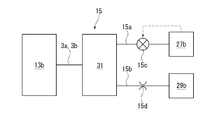
- FIG. 3 is a schematic diagram illustrating a control mechanism in the variable capacity compressor according to the first embodiment.
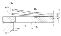
- FIG. 4 is a partial cross-sectional view illustrating the second discharge hole, the second valve seat surface, and the second discharge reed valve according to the variable capacity compressor of the first embodiment.
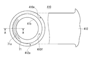
- FIG. 5 is a partial top view showing the second discharge hole, the second valve seat surface, the second discharge reed valve, and the second backflow portion in the variable capacity compressor according to the first embodiment.
- FIG. 6 is a partial cross-sectional view showing the AA cross section of FIG.
- FIG. 7 is a graph showing the relationship between the discharge capacity and the variable differential pressure during low-speed operation in the variable capacity compressor of the first embodiment.
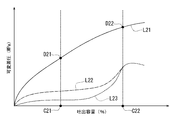
- FIG. 8 is a graph showing the relationship between the discharge capacity and the variable differential pressure during high-speed operation in the variable capacity compressor according to the first embodiment.
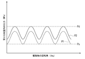
- FIG. 9 is a graph showing the relationship between the rotation angle of the drive shaft and the pressure in the second compression chamber during low speed operation and low capacity, in the variable capacity compressor of the first embodiment.
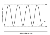
- FIG. 10 is a graph showing the relationship between the rotation angle of the drive shaft and the pressure in the second compression chamber during low speed operation and high capacity, in the variable capacity compressor of Example 1.
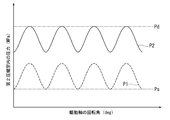
- FIG. 11 is a graph showing the relationship between the rotation angle of the drive shaft and the pressure in the second compression chamber during high speed operation and low capacity, in the variable capacity compressor of the first embodiment.
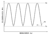
- FIG. 12 is a graph showing the relationship between the rotation angle of the drive shaft and the pressure in the second compression chamber during high speed operation and high capacity, in the variable capacity compressor of the first embodiment.
- FIG. 13 is a partial top view showing a second discharge hole, a second valve seat surface, a second discharge reed valve, and a second backflow portion in the variable capacity compressor according to the second embodiment.
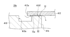
- 14 is a partial cross-sectional view showing a BB cross section of FIG. 13 according to the variable capacity compressor of the second embodiment.
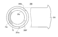
- FIG. 15 is a partial cross-sectional view illustrating a first suction hole, a first valve seat surface, and a first suction reed valve according to the variable capacity compressor of the third embodiment.
- FIG. 16 is a partial bottom view showing the first suction hole, the first valve seat surface, the first suction reed valve, and the first backflow portion in the variable capacity compressor of the third embodiment.
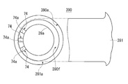
- FIG. 17 is a partial bottom view showing the first suction hole, the first valve seat surface, the first suction reed valve, and the first backflow portion in the variable capacity compressor of the fourth embodiment.
- Embodiments 1 to 4 embodying the present invention will be described below with reference to the drawings.
- Example 1 As shown in FIG.1 and FIG.2, the compressor of Example 1 is an example of the specific aspect of the capacity
- This compressor employs a double-headed piston.
- This compressor is mounted on a vehicle and constitutes a refrigeration circuit of a vehicle air conditioner. 1 and 2, the direction in which the drive axis O1 of the drive shaft 3 extends is the front-rear direction of the compressor. 1 and 2, the left side of the drawing is the front of the compressor, and the right side of the drawing is the rear of the compressor.
- the compressor includes a housing 1, a drive shaft 3, a swash plate 5, a link mechanism 7, a plurality of pistons 9, and an actuator 13. Moreover, this compressor is provided with the control mechanism 15 as shown in FIG.
- the housing 1 includes a first housing 17, a second housing 19, a first cylinder block 21, a second cylinder block 23, a first valve forming plate 39, and a second housing. And an annuloplasty plate 41.
- the first housing 17 is formed with a boss 17a protruding forward.
- a shaft seal device 25 is provided in the boss 17a.
- a first suction chamber 27a and a first discharge chamber 29a are formed in the first housing 17.
- the first suction chamber 27 a is formed in an annular shape and is located on the inner peripheral side of the first housing 17.
- the first discharge chamber 29 a is also formed in an annular shape, and is positioned on the outer peripheral side of the first suction chamber 27 a in the first housing 17.
- the second housing 19 is provided with a part of the control mechanism 15 described above.
- a second suction chamber 27b, a second discharge chamber 29b, and a pressure adjustment chamber 31 are formed in the second housing 19.
- the pressure adjustment chamber 31 is located in the central portion of the second housing 19.
- the second suction chamber 27 b is formed in an annular shape, and is located on the outer peripheral side of the pressure adjustment chamber 31 in the second housing 19.
- the second discharge chamber 29 b is also formed in an annular shape, and is positioned on the outer peripheral side of the second suction chamber 27 b in the second housing 19.
- the first cylinder block 21 is provided on the front side of the compressor and between the first housing 17 and the second cylinder block 23.
- the first cylinder block 21 is formed with a plurality of first cylinder bores 21a extending in the direction of the drive axis O1.
- the first cylinder bores 21a are arranged at equiangular intervals in the circumferential direction.
- first cylinder block 21 is formed with a first shaft hole 21b through which the drive shaft 3 is inserted.
- a first sliding bearing 22a is provided in the first shaft hole 21b.
- the first cylinder block 21 is formed with a first recess 21c.
- the first recess 21c communicates with the first shaft hole 21b from the rear side of the compressor.
- the first recess 21c is coaxial with the first shaft hole 21b and has an inner diameter larger than that of the first shaft hole 21b.
- a first thrust bearing 35a is provided in the first recess 21c.
- the second cylinder block 23 is provided on the rear side of the compressor and between the first cylinder block 21 and the second housing 19.
- the second cylinder block 23 is joined to the first cylinder block 21, thereby forming a swash plate chamber 33 with the first cylinder block 21.
- the swash plate chamber 33 communicates with the first recess 21c.
- the first recess 21 c constitutes a part of the swash plate chamber 33.
- the second cylinder block 23 is formed with a plurality of second cylinder bores 23a extending in the direction of the drive axis O1.
- Each of the second cylinder bores 23a is arranged at equiangular intervals in the circumferential direction, like the first cylinder bores 21a.
- Each second cylinder bore 23a is paired with each first cylinder bore 21a at the front and rear.
- the first cylinder bores 21a and the second cylinder bores 23a are formed to have the same inner diameter.
- these numbers and internal diameter can be designed suitably.
- the second cylinder block 23 is formed with a second shaft hole 23b through which the drive shaft 3 is inserted, and a second recess 23c communicating with the second shaft hole 23b from the front side of the compressor.
- a second sliding bearing 22b is provided in the second shaft hole 23b.
- rolling bearings may be provided.
- the second recess 23c is coaxial with the second shaft hole 23b and has an inner diameter larger than that of the second shaft hole 23b.
- the second recess 23 c is also in communication with the swash plate chamber 33 and constitutes a part of the swash plate chamber 33.
- a second thrust bearing 35b is provided in the second recess 23c.
- the first valve forming plate 39 is provided between the first housing 17 and the first cylinder block 21.
- the first housing 17 and the first cylinder block 21 are joined via the first valve forming plate 39.
- the second valve forming plate 41 is provided between the second housing 19 and the second cylinder block 23.
- the second housing 19 and the second cylinder block 23 are joined via the second valve forming plate 41.
- the first valve forming plate 39 includes a first valve plate 390, a first suction valve plate 391, a first discharge valve plate 392, and a first retainer plate 393.
- the first valve plate 390 and the first intake valve plate 391 extend to the outer circumferences of the first housing 17 and the first cylinder block 21.
- first suction holes 39a are formed in the first valve plate 390, the first discharge valve plate 392, and the first retainer plate 393. Each first cylinder bore 21a communicates with the first suction chamber 27a through each first suction hole 39a.
- first discharge holes 39b are formed in the first valve plate 390 and the first intake valve plate 391.
- Each first cylinder bore 21a communicates with the first discharge chamber 29a through each first discharge hole 39b.
- the first intake valve plate 391 is provided on the rear surface of the first valve plate 390.
- the first suction valve plate 391 is formed with a plurality of first suction reed valves 391a that can open and close each first suction hole 39a by elastic deformation.
- the first discharge valve plate 392 is provided on the front surface of the first valve plate 390.
- the first discharge valve plate 392 is formed with a plurality of first discharge reed valves 392a that can open and close each first discharge hole 39b by elastic deformation.
- the first retainer plate 393 is provided on the front surface of the first discharge valve plate 392. The first retainer plate 393 regulates the maximum opening degree of each first discharge reed valve 392a.
- the second valve forming plate 41 includes a second valve plate 410, a second suction valve plate 411, a second discharge valve plate 412, and a second retainer plate 413.
- the second valve plate 410 and the second intake valve plate 411 extend to the outer circumferences of the second housing 19 and the second cylinder block 23.
- each second cylinder bore 23a communicates with the second suction chamber 27b through each second suction hole 41a.
- the same number of second discharge holes 41b as the second cylinder bores 23a are formed in the second valve plate 410 and the second intake valve plate 411. Each second cylinder bore 23a communicates with the second discharge chamber 29b through each second discharge hole 41b.
- annular groove 410e and a second valve seat surface 410f are formed on the rear surface of the second valve plate 410 corresponding to each of the second discharge holes 41b.
- the annular groove 410e is recessed forward from the rear surface of the second valve plate 410 and surrounds the entire circumference of the second discharge hole 41b.
- the second valve seat surface 410f is an annular flat surface that surrounds the second discharge hole 41b inside the annular groove 410e.
- the second suction valve plate 411 is provided on the front surface of the second valve plate 410.
- the second suction valve plate 411 is formed with a plurality of second suction reed valves 411a capable of opening and closing each second suction hole 41a by elastic deformation.
- the second discharge valve plate 412 is provided on the rear surface of the second valve plate 410.
- the second discharge valve plate 412 is formed with a plurality of second discharge reed valves 412a that can open and close each second discharge hole 41b by elastic deformation.
- the second retainer plate 413 is provided on the rear surface of the second discharge valve plate 412. The second retainer plate 413 regulates the maximum opening degree of each second discharge reed valve 412a. As shown in FIGS. 4 and 5, the second discharge reed valve 412a opens and closes the second discharge hole 41b by being seated and separated from the second valve seat surface 410f.
- the second valve plate 410 is provided with a second backflow portion 71.
- the second backflow portion 71 includes irregularities 71a formed in a partial region of the second valve seat surface 410f.
- the unevenness 71a is formed by shot processing on a partial region of the second valve seat surface 410f. Shot processing is a processing method for finishing a metal surface by spraying or striking particles such as fine sand or metal spheres on the metal surface.
- the second backflow portion 71 has the second discharge reed valve 412a and the second valve seat surface 410f in the state where the second discharge reed valve 412a is seated on the second valve seat surface 410f.
- a gap S1 is formed between the two.
- the depth of the concave portion and the size of the concave portion in the unevenness 71a are determined by the lubricating oil interposed between the second discharge reed valve 412a seated on the second valve seat surface 410f and the second valve seat surface 410f.
- the gap S1 is not filled, and the second discharge chamber 29b and a second compression chamber 53b described later are set to communicate with each other through the gap S1.
- the second backflow portion 71 leaks the refrigerant in the second discharge chamber 29b into the second compression chamber 53b through the second discharge hole 41b, and causes the pressure P2 in the second compression chamber 53b to enter the swash plate chamber 33. Higher than the suction pressure Ps.
- the second cylinder block 23 is formed with a discharge port 23d, a merged discharge chamber 23j, and a suction port 23s.
- the discharge port 23d and the merged discharge chamber 23j communicate with each other.
- the merged discharge chamber 23j is connected to a condenser (not shown) that constitutes a pipe line of the refrigeration circuit via a discharge port 23d.
- the suction port 23s and the swash plate chamber 33 communicate with each other.
- the swash plate chamber 33 is connected to an evaporator (not shown) constituting a pipe line of the refrigeration circuit via a suction port 23s.
- the first discharge communication passage 18 is formed in the first housing 17, the first valve forming plate 39, the first cylinder block 21 and the second cylinder block 23.
- the front end side of the first discharge communication path 18 communicates with the first discharge chamber 29a, and the rear end side communicates with the merged discharge chamber 23j.
- a second discharge communication passage 20 is formed in the second cylinder block 23, the second valve forming plate 41, and the second housing 19.
- the rear end side of the second discharge communication passage 20 communicates with the second discharge chamber 29b, and the front end side communicates with the merged discharge chamber 23j.
- first and second discharge chambers 29a and 29b and the merged discharge chamber 23j communicate with each other through the first and second discharge communication passages 18 and 20. For this reason, the pressure in the first and second discharge chambers 29a and 29b and the pressure in the merged discharge chamber 23j are the discharge pressure Pd.
- a first communication path 37a is formed in the first cylinder block 21 and the first valve forming plate 39.
- the first communication path 37 a has a front end side communicating with the first suction chamber 27 a and a rear end side communicating with the swash plate chamber 33.
- a second communication path 37b is formed in the second cylinder block 23 and the second valve forming plate 41.
- the second communication path 37 b has a rear end side communicating with the second suction chamber 27 b and a front end side communicating with the swash plate chamber 33.
- first and second suction chambers 27a and 27b and the swash plate chamber 33 communicate with each other through the first and second communication paths 37a and 37b. For this reason, the pressure in the first and second suction chambers 27a and 27b and the pressure in the swash plate chamber 33 are the suction pressure Ps.
- the drive shaft 3 includes a drive shaft main body 30, a first support member 43a, and a second support member 43b.
- the drive shaft main body 30 extends from the front of the housing 1 toward the rear in the direction of the drive axis O1.
- a first small diameter portion 30 a is formed on the front end side of the drive shaft main body 30.
- a second small diameter portion 30 b is formed on the rear end side of the drive shaft main body 30.
- the drive shaft body 30 is inserted into the shaft sealing device 25 and the first and second sliding bearings 22a and 22b in the housing 1. As a result, the drive shaft main body 30, and thus the drive shaft 3, is supported by the housing 1 so as to be rotatable around the drive axis O1.
- the front end of the drive shaft body 30 is inserted through the shaft seal device 25 in the boss 17a.
- the rear end of the drive shaft main body 30 protrudes into the pressure adjustment chamber 31.
- the drive shaft main body 30 is provided with the swash plate 5, the link mechanism 7, and the actuator 13.
- the swash plate 5, the link mechanism 7, and the actuator 13 are respectively disposed in the swash plate chamber 33.
- Threaded portion 3e is formed at the front end of drive shaft body 30.
- the drive shaft 3 is connected to a pulley or an electromagnetic clutch (not shown) via a screw portion 3e.
- the first support member 43a is formed in a substantially cylindrical shape with the drive axis O1 as the central axis.
- the first support member 43 a is press-fitted into the first small diameter portion 30 a of the drive shaft body 30 and is integrated with the drive shaft body 30.
- the first support member 43a is supported by the first sliding bearing 22a in the first shaft hole 21b.
- a first flange 43f and a mounting portion (not shown) through which a second pin 47b described later is inserted are formed on the rear end side of the first support member 43a.
- the first thrust bearing 35a is held in the direction of the drive axis O1 by the first flange 43f and the front wall of the first recess 21c. As a result, a predetermined preload is applied to the first thrust bearing 35a, and the thrust force toward the front end side of the compressor acting on the drive shaft body 30 including the first support member 43a during operation is supported.
- the second support member 43b is formed in a cylindrical shape having the drive axis O1 as a central axis.
- the second support member 43b is press-fitted into the second small diameter portion 30b of the drive shaft main body 30, and is supported by the second sliding bearing 22b in the second shaft hole 23b.
- a second flange 43g is formed at the front end of the second support member 43b.
- the second thrust bearing 35b is held in the direction of the drive axis O1 by the second flange 43g and the rear wall of the second recess 23c. Thus, a predetermined preload is applied to the second thrust bearing 35b, and the thrust force toward the rear end side of the compressor acting on the drive shaft main body 30 including the second support member 43b during operation is supported.
- the swash plate 5 has a substantially disk shape and has a front surface 5a and a rear surface 5b.
- the front surface 5 a faces the front of the compressor in the swash plate chamber 33.
- the rear surface 5 b faces the rear of the compressor in the swash plate chamber 33.
- the swash plate 5 can be inclined with respect to the direction orthogonal to the drive axis O1.
- the swash plate 5 has a ring plate 45.
- the ring plate 45 is formed in an annular flat plate shape.
- An insertion hole 45 a is formed at the center of the ring plate 45.
- the swash plate 5 is attached to the drive shaft 3 by inserting the drive shaft main body 30 through the insertion hole 45 a in the swash plate chamber 33.
- the ring plate 45 is formed with a connecting portion 45c connected to a connecting arm 132 described later so as to protrude toward the rear of the compressor.
- a return spring 44 a is provided between the first flange 43 f and the ring plate 45. Specifically, the front end of the return spring 44a is disposed so as to contact the first flange 43f. The rear end of the return spring 44 a is disposed so as to contact the ring plate 45. The return spring 44a biases both the first flange 43f and the ring plate 45 so as to separate each other.
- the link mechanism 7 includes a lug arm 49, a first pin 47a, and a second pin 47b.
- the lug arm 49 is disposed in front of the swash plate 5 in the swash plate chamber 33, and is located between the swash plate 5 and the first support member 43a.
- the lug arm 49 is formed to be substantially L-shaped from the front end side toward the rear end side.
- a weight portion 49a is formed on the rear end side of the lug arm 49.
- the weight portion 49 a extends in the circumferential direction of the actuator 13 and covers approximately half the circumference of the actuator 13.
- the shape of the weight portion 49a can be designed as appropriate. Centrifugal force acts on the weight portion 49a as the swash plate 5 rotates around the drive axis O1.
- the first pin 47 a connects the rear end side of the lug arm 49 and the ring plate 45.
- the lug arm 49 is supported by the swash plate 5 so as to be able to swing around the first swing axis M1 with the first pin 47a as the first swing axis M1.
- the first swing axis M1 extends in a direction orthogonal to the drive axis O1.
- the second pin 47b connects the front end side of the lug arm 49 and the first support member 43a.
- the lug arm 49 can swing around the second swing axis M2 with respect to the first support member 43a, that is, the drive shaft 3, with the second pivot 47b serving as the second pivot axis M2. It is supported.
- the second swing axis M2 extends in parallel with the first swing axis M1.
- the swash plate 5 and the drive shaft 3 are connected by the link mechanism 7 so that the swash plate 5 can rotate together with the drive shaft 3.
- the inclination angle of the swash plate 5 with respect to the direction perpendicular to the drive axis O1 is as shown in FIG. Can be changed from the maximum state shown in FIG. 2 to the minimum state shown in FIG.
- each piston 9 is a double-headed piston, and has a first head 9a on the front end side and a second head 9b on the rear end side.
- Each first head 9a is accommodated in each first cylinder bore 21a so as to reciprocate.
- the first compression chambers 53a are defined in the first cylinder bores 21a by the first heads 9a and the first valve forming plate 39, respectively.
- Each of the second heads 9b is accommodated so as to be able to reciprocate within each of the second cylinder bores 23a.
- a second compression chamber 53b is defined in each second cylinder bore 23a by each second head 9b and the second valve forming plate 41.
- a piston ring 9s is provided on the outer peripheral surface of the second head 9b.
- the piston ring 9s seals between the outer peripheral surface of the second head 9b and the inner peripheral surface of the second cylinder bore 23a. Thereby, it can suppress that the refrigerant
- An engaging portion 9c is formed at the center of each piston 9 in the direction of the drive axis O1.
- each engaging portion 9c hemispherical shoes 11a and 11b are provided.
- Each shoe 11 a slides on the front surface 5 a of the swash plate 5.
- each shoe 11b slides on the rear surface 5b of the swash plate 5.
- Each first head 9 a can reciprocate in the first cylinder bore 21 a with a stroke corresponding to the inclination angle of the swash plate 5.
- Each of the second heads 9b can reciprocate in the second cylinder bore 23a with a stroke corresponding to the inclination angle of the swash plate 5.
- the top dead center positions of the first heads 9a and the second heads 9b move as the strokes of the pistons 9 change as the inclination angle of the swash plate 5 changes.
- the top dead center position of each second head 9b moves larger than the top dead center position of each first head 9a.
- the compression work in the second compression chamber 53b is reduced than the compression work in the first compression chamber 53a.
- the top dead center position of the first head 9a slightly moves and the dead space of the first compression chamber 53a slightly changes.
- the top dead center position of the second head 9b has moved greatly, and the dead space of the second compression chamber 53b has changed greatly.
- the actuator 13 is disposed in the swash plate chamber 33.
- the actuator 13 is positioned behind the swash plate 5 in the swash plate chamber 33 and can enter the second recess 23c.
- the actuator 13 has a partition 13c, a moving body 13a, and a control pressure chamber 13b.
- the partition 13c has a substantially disk shape extending in the radially outward direction of the drive shaft O1.
- An insertion hole 133 is provided through the center of the partition 13c.
- An O-ring 139b is provided on the outer periphery of the partition 13c.
- the drive shaft main body 30 is press-fitted into the insertion hole 133 of the partition 13c. Thereby, the partition 13c can rotate integrally with the drive shaft main body 30 at a position facing the swash plate 5 from the rear.
- the moving body 13a has a rear wall 130, a peripheral wall 131, and a pair of pulling arms 132. 1 and 2, only one of the pair of pulling arms 132 is shown.
- the rear wall 130 is located behind the movable body 13a and has a substantially disk shape extending in the radially outward direction of the drive shaft O1.
- the rear wall 130 is provided with an insertion hole 130a through which the second small diameter portion 30b of the drive shaft main body 30 is inserted.
- An O-ring 139a is provided in the insertion hole 130a.
- the peripheral wall 131 is continuous with the outer peripheral edge of the rear wall 130 and extends in a cylindrical shape toward the front of the moving body 13a.
- the inner diameter of the peripheral wall 131 is slightly larger than the outer diameter of the partition 13c.
- Each traction arm 132 is formed at the front end of the peripheral wall 131 with the drive axis O1 interposed therebetween, and projects toward the front of the movable body 13a.
- Each pulling arm 132 and the ring plate 45 are connected by a third pin 47c. Accordingly, the swash plate 5 is supported by the movable body 13a so as to be swingable around the action axis M3 with the axis of the third pin 47c as the action axis M3.
- the action axis M3 extends in parallel with the first and second oscillation axes M1 and M2.
- the second small diameter portion 30b of the drive shaft main body 30 is inserted through the insertion hole 130a of the moving body 13a.
- a space between the insertion hole 130a and the second small diameter portion 30b is sealed by an O-ring 139a.
- the movable body 13a can move the second small diameter portion 30b of the drive shaft main body 30 in the direction of the drive axis O1.
- a partition 13c is arranged in the moving body 13a.
- the peripheral wall 131 surrounds the partition 13c.
- a space between the inner peripheral surface of the peripheral wall 131 and the outer peripheral surface of the partition 13c is sealed by an O-ring 139b.
- the control pressure chamber 13 b is formed by being surrounded by the rear wall 130 and the peripheral wall 131 of the movable body 13 a and the partition body 13 c, and is partitioned from the swash plate chamber 33.
- an inclination reduction spring 44b is provided between the moving body 13a and the second support member 43b. Specifically, the front end of the inclination-decreasing spring 44b is disposed so as to contact the rear wall 130 of the moving body 13a. The rear end of the inclination-decreasing spring 44b is disposed so as to contact the second flange 43g of the second support member 43b. The inclination-decreasing spring 44b biases both the moving body 13a and the second support member 43b so as to separate each other.
- An axial path 3a and a radial path 3b are formed in the second small diameter portion 30b.
- the axial path 3a extends in the direction of the drive axis O1 from the rear end of the second small diameter portion 30b toward the front.
- the radial path 3 b extends in the radial direction from the front end of the axial path 3 a and opens on the outer peripheral surface of the drive shaft main body 30.
- the rear end of the axial path 3 a communicates with the pressure adjustment chamber 31.
- the path 3b communicates with the control pressure chamber 13b. Thereby, the pressure in the control pressure chamber 13b and the pressure in the pressure adjustment chamber 31 are the control pressure Pc.
- control mechanism 15 includes a low pressure passage 15a, a high pressure passage 15b, a control valve 15c, an orifice 15d, an axial passage 3a, and a radial passage 3b.
- the low pressure passage 15a is connected to the pressure adjusting chamber 31 and the second suction chamber 27b.
- the control pressure chamber 13b, the pressure adjustment chamber 31, and the second suction chamber 27b communicate with each other through the low pressure passage 15a, the axial path 3a, and the radial path 3b.
- the high-pressure passage 15b is connected to the pressure adjustment chamber 31 and the second discharge chamber 29b.
- the control pressure chamber 13b, the pressure adjustment chamber 31, and the second discharge chamber 29b communicate with each other by the high pressure passage 15b, the axial path 3a, and the radial path 3b.
- An orifice 15d is provided in the high-pressure passage 15b.
- the control valve 15c is provided in the low pressure passage 15a.
- the control valve 15c can adjust the opening of the low pressure passage 15a based on the pressure in the second suction chamber 27b.
- a pipe connected to the evaporator is connected to the suction port 23s.
- a pipe connected to the condenser is connected to the discharge port 23d.
- the condenser is connected to the evaporator via a pipe and an expansion valve.
- a compressor, an evaporator, an expansion valve, a condenser, and the like constitute a refrigeration circuit for a vehicle air conditioner.
- illustration of an evaporator, an expansion valve, a condenser, etc. is abbreviate
- the first and second compression chambers 53a and 53b change the volume according to the piston stroke.
- the refrigerant taken into the first and second suction chambers 27a and 27b with the suction pressure Ps is compressed in the first and second compression chambers 53a and 53b, and then into the first and second discharge chambers 29a and 29b with the discharge pressure Pd. Discharged.
- the refrigerant discharged into the first discharge chamber 29a reaches the merged discharge chamber 23j through the first discharge communication path 18.
- the refrigerant discharged into the second discharge chamber 29b reaches the merged discharge chamber 23j through the second discharge communication path 20.
- merging discharge chamber 23j is discharged to a condenser via piping from discharge port 23d.
- the refrigerant in the second discharge chamber 29b leaks into the second compression chamber 53b by the second counterflow portion 71 shown in FIGS.
- the actuator 13 changes the inclination angle of the swash plate 5 with respect to the direction orthogonal to the drive axis O1 of the drive shaft 3 to increase or decrease the stroke of each piston 9. To change the discharge capacity.
- the moving body 13a pulls the swash plate 5 to the rear in the swash plate chamber 33 through the respective pulling arms 132 and the third pins 47c while resisting the biasing force of the inclination decreasing spring 44b. Therefore, the swash plate 5 swings counterclockwise around the first swing axis M1. Further, the front end of the lug arm 49 swings clockwise around the second swing axis M2 and is separated rearward from the first flange 43f of the first support member 43a. As a result, the inclination angle of the swash plate 5 increases. For this reason, in this compressor, the stroke of each piston 9 increases and the discharge capacity per rotation of the drive shaft 3 increases. In the state where the inclination angle of the swash plate 5 shown in FIG. 1 is maximum, the stroke of each piston 9 becomes maximum, and the discharge capacity per one rotation of the drive shaft 3 becomes the maximum capacity.
- the swash plate 5 is urged in a direction in which the inclination angle becomes smaller by the compression reaction force acting on the swash plate 5 via each piston 9. Therefore, the moving body 13a is pulled forward of the swash plate chamber 33 through each pulling arm 132 and the third pin 47c while resisting the biasing force of the return spring 44a. For this reason, the swash plate 5 swings clockwise around the first swing axis M1. Further, the front end of the lug arm 49 swings counterclockwise around the second swing axis M2 and approaches the first flange 43f of the first support member 43a. As a result, the inclination angle of the swash plate 5 is reduced.
- the compressor according to the first embodiment may be used in a state where a clutch (not shown) is interposed between a drive source such as an engine and the drive shaft 3.
- a clutch not shown
- the driving shaft 3 stops and the compression reaction force does not act on the swash plate 5.
- the second backflow portion 71 has the second discharge reed valve 412a and the second valve seat by the unevenness 71a in a state where the second discharge reed valve 412a is seated on the second valve seat surface 410f.
- a gap S1 is formed between the surface 410f. Due to the gap S1, the second discharge chamber 29b and the second compression chamber 53b communicate with each other through the second discharge hole 41b. Thereby, the second backflow portion 71 leaks the refrigerant in the second discharge chamber 29b into the second compression chamber 53b, and makes the pressure P2 in the second compression chamber 53b higher than the suction pressure Ps in the swash plate chamber 33. . That is, the inclination angle of the swash plate 5 can be easily reduced by the pressure difference between the second compression chamber 53 b and the swash plate chamber 33 generated by the second counterflow portion 71.
- the restart after the clutch is operated can be smoothly performed.
- the necessity of providing a margin for control in order to prevent the engine or the like that is the drive source from being stopped is reduced, and a reduction in the efficiency of the drive source such as a deterioration in fuel consumption can be suppressed.
- the necessity of increasing the biasing force of the inclination reduction spring 44b or the like for reducing the inclination angle of the swash plate 5 is reduced, and the housing 1 that accommodates the inclination reduction spring 44b or the like can be easily downsized.
- the second counterflow portion 71 leaks the refrigerant in the second discharge chamber 29b into the second compression chamber 53b, and the pressure P2 in the second compression chamber 53b is swash plate chamber. It is made higher than the suction pressure Ps in 33.
- FIG. 7 shows a low-speed operation when the rotational speed of the drive shaft 3 is low.
- the differential pressure (Pd ⁇ Ps) between the discharge pressure Pd and the suction pressure Ps increases as shown by a curve L11.
- FIG. 8 shows a high-speed operation when the rotational speed of the drive shaft 3 is high.
- the differential pressure (Pd ⁇ Ps) increases as shown by a curve L21.
- the differential pressure (Pd ⁇ Ps) is higher in the high speed operation shown in FIG. 8 than in the low speed operation shown in FIG. 7 when the discharge capacity is equal.
- FIG. 9 to 12 show the waveform of the pressure P2 in the second compression chamber 53b according to the present embodiment and the waveform of the pressure P1 in the second compression chamber 53b according to the comparative example.
- the second backflow portion 71 is provided in the second valve plate 410, whereas in the comparative example, the second backflow portion 71 is not provided in the second valve plate 410.
- the waveforms of the pressures P1 and P2 each periodically change as the rotation angle of the drive shaft 3 increases.
- FIG. 9 shows a low-capacity state during low-speed operation and a small inclination angle of the swash plate 5, that is, a state indicated by a point C11 in FIG.
- FIG. 10 shows a high capacity state during low speed operation and a large inclination angle of the swash plate 5, that is, a state indicated by C12 in FIG.
- FIG. 11 shows a state at a high speed operation and a low capacity, that is, a state indicated by C21 in FIG.
- FIG. 12 shows a state at high speed operation and a high capacity, that is, a state indicated by C22 in FIG.
- the suction pressure Ps shown in FIGS. 9 to 12 is substantially constant.
- the discharge pressure Pd shown in FIG. 9 corresponds to the point D11 shown in FIG.
- the discharge pressure Pd shown in FIG. 10 corresponds to the point D12 shown in FIG.
- the discharge pressure Pd shown in FIG. 11 corresponds to the point D21 shown in FIG.
- the discharge pressure Pd shown in FIG. 12 corresponds to the point D22 shown in FIG. That is, the discharge pressure Pd is the lowest during the low speed operation and low capacity shown in FIG. 9, the high speed operation and low capacity shown in FIG. 11, the low speed operation and high capacity shown in FIG. 12 in order of high speed operation and high capacity.
- the valley portion is substantially equal to the suction pressure Ps.
- the fluctuation waveform of the pressure P2 in the second compression chamber 53b according to the present embodiment is a comparative example because the second backflow portion 71 leaks the refrigerant in the second discharge chamber 29b into the second compression chamber 53b. It is shifted upward from the fluctuation waveform of the pressure P1 in the second compression chamber 53b.
- the valley portion of the fluctuation waveform of the pressure P2 in the second compression chamber 53b according to the present embodiment is also shifted upward from the suction pressure Ps.
- the degree of deviation of the fluctuation waveforms of the pressures P1 and P2 is greatest at the time of high speed operation shown in FIG. 11 and at the time of low capacity, and at the time of low speed operation and high capacity shown in FIG. In addition, it is small when the capacity is high, and is intermediate between the low speed operation and the low capacity shown in FIG.
- the compression reaction force acting on the second head 9b can be effectively increased as compared with the conventional case when the capacity is low as shown in FIGS.
- the compression reaction force acting on the second head 9b can be increased more effectively than in the prior art during high speed operation and low capacity as shown in FIG.
- the action of the compression reaction force to reduce the inclination angle of the swash plate 5 can be suitably exhibited.
- variable differential pressure which is the differential pressure between the control pressure Pc in the control pressure chamber 13b and the suction pressure Ps in the swash plate chamber 33, increases as shown by the curve L12.
- the variable differential pressure (Pc ⁇ Ps) increases as shown by the curve L13 during the low speed operation shown in FIG. Due to the action of the second backflow portion 71, the curve L12 is slightly shifted upward with respect to the curve L13.
- variable differential pressure (Pc ⁇ Ps) increases as shown by the curve L22.
- the variable differential pressure (Pc ⁇ Ps) increases as shown by the curve L23 during the high speed operation shown in FIG. Due to the action of the second backflow portion 71, the curve L22 is largely displaced upward with respect to the curve L23.
- the movable body 13a that changes the inclination angle of the swash plate 5 during the high-speed operation shown in FIG. 8 because the compression reaction force acting on the second head 9b by the second counterflow portion 71 can be made larger than before. Therefore, the control pressure Pc in the control pressure chamber 13b increases.
- the controllability of the inclination angle of the swash plate 5 during high speed operation can be improved.
- the tilt angle reducing spring 44 b is provided as much as the compression reaction force acting on the second head 9 b by the second counterflow portion 71 can be made larger than before.
- the space for disposing the inclination-decreasing spring 44b in the housing 1 can be reduced.
- this compressor can achieve downsizing in the direction of the drive axis O1.
- the piston ring 9s provided on the outer peripheral surface of the second head 9b is connected to the outer peripheral surface of the second head 9b and the inner periphery of the second cylinder bore 23a. Seal between the faces. Thereby, it can suppress that the refrigerant
- the second backflow portion 71 has a simple configuration including the unevenness 71 a formed on the second valve seat surface 410 f by shot processing, so that the manufacturing cost can be reduced. Soaring can be suppressed.
- Example 2 As shown in FIGS. 13 and 14, the compressor of the second embodiment employs a second counterflow portion 72 instead of the second counterflow portion 71 according to the compressor of the first embodiment.
- Other configurations of the second embodiment are the same as those of the first embodiment. For this reason, about the same structure as Example 1, the same code
- the second valve plate 410 is provided with a second backflow portion 72.
- the first valve plate 390 is not provided with the second backflow portion 72.
- the second backflow portion 72 includes a plurality of steps 72a that are recessed in a partial region of the second valve seat surface 410f.
- the step 72a is a groove formed by cutting or the like on a partial region of the second valve seat surface 410f.
- One end of the step 72a communicates with the second discharge hole 41b.
- the other end of the step 72a communicates with the annular groove 410e.
- the second backflow portion 72 is separated from the second discharge reed valve 412a and the second valve seat surface 410f by the step 72a.
- a gap S2 is formed between the two.
- the depth of the step 72a, the groove width of the step 72a, and the like are determined by the lubricating oil interposed between the second discharge reed valve 412a seated on the second valve seat surface 410f and the second valve seat surface 410f.
- the gap S2 is not filled, and the second discharge chamber 29b and the second compression chamber 53b are set to communicate with each other through the gap S2.
- the second backflow portion 72 leaks the refrigerant in the second discharge chamber 29b into the second compression chamber 53b via the second discharge hole 41b, and the pressure P2 in the second compression chamber 53b is transferred into the swash plate chamber 33. Higher than the suction pressure Ps.
- the compressor of the second embodiment can improve the controllability of the inclination angle of the swash plate 5 during high-speed operation, similarly to the compressor of the first embodiment.
- this compressor can also achieve downsizing in the direction of the drive axis O1. Further, this compressor can also improve the compression performance when the capacity is variable.
- the 2nd backflow part 72 is the simple structure containing the level
- Example 3 As shown in FIG.15 and FIG.16, the compressor of Example 3 adds the 1st backflow part 73 to the compressor of Example 1.
- Other configurations of the third embodiment are the same as those of the first embodiment. For this reason, about the same structure as Example 1, the same code
- annular groove 390e and a first valve seat surface 390f are formed on the front surface of the first valve plate 390 corresponding to each of the first suction holes 39a.
- the annular groove 390e is recessed rearward from the front surface of the first valve plate 390 and surrounds the entire circumference of the first suction hole 39a.
- the first valve seat surface 390f is an annular flat surface surrounding the first suction hole 39a inside the annular groove 390e.
- the first valve plate 390 is provided with a first backflow portion 73.
- the second valve plate 410 is not provided with the first backflow portion 73.
- the first backflow portion 73 includes unevenness 73a formed in a partial region of the first valve seat surface 390f.
- the unevenness 73a is formed by the above-described shot processing on a partial region of the first valve seat surface 390f.
- the first backflow portion 73 forms a gap between the first suction reed valve 391a and the first valve seat surface 390f by the unevenness 73a in a state where the first suction reed valve 391a is seated on the first valve seat surface 390f. To do.
- the clearance between the first suction reed valve 391a and the first valve seat surface 390f is the same as the clearance S1 between the second discharge reed valve 412a and the second valve seat surface 410f shown in FIG.
- the depth of the recesses and the size of the recesses in the unevenness 73a are determined by the lubricating oil interposed between the first intake reed valve 391a seated on the first valve seat surface 390f and the first valve seat surface 390f. Also, the gap between the first suction reed valve 391a and the first valve seat surface 390f is not filled, and the first suction chamber 27a and the first compression chamber 53a are set to communicate with each other through the gap. Thereby, the 1st backflow part 73 leaks the refrigerant
- the compressor according to the third embodiment may be used in a state where a clutch (not shown) is interposed between a drive source such as an engine and the drive shaft 3.
- a clutch not shown
- the driving shaft 3 stops and the compression reaction force does not act on the swash plate 5.
- the swash plate 5 is biased so as to reduce the inclination angle by the inclination angle reducing spring 44b and the like.
- the first backflow portion 73 causes the refrigerant in the first compression chamber 53a to flow into the first suction chamber 27a. To leak. That is, the inside of the first compression chamber 53a does not become a closed space by the first backflow portion 73, and resistance to reducing the inclination angle of the swash plate 5 is less likely to occur. It is easy to reduce the inclination angle of 5.
- the restart after the clutch is operated can be smoothly performed.
- the necessity of providing a margin for control in order to prevent the engine or the like that is the drive source from being stopped is reduced, and a reduction in the efficiency of the drive source such as a deterioration in fuel consumption can be suppressed.
- the necessity of increasing the biasing force of the inclination reduction spring 44b or the like for reducing the inclination angle of the swash plate 5 is reduced, and the housing 1 that accommodates the inclination reduction spring 44b or the like can be easily downsized.
- the 1st backflow part 73 is the simple structure containing the unevenness
- Example 4 As illustrated in FIG. 17, the compressor according to the fourth embodiment employs a first counterflow portion 74 instead of the first counterflow portion 73 according to the compressor according to the third embodiment.
- Other configurations of the fourth embodiment are the same as those of the first and third embodiments. For this reason, the same components as those in the first and third embodiments are denoted by the same reference numerals, and description thereof is omitted or simplified.
- the first valve plate 390 is provided with a first backflow portion 74.
- the second valve plate 410 is not provided with the first backflow portion 74.
- the first backflow portion 74 includes a plurality of steps 74a that are recessed in a partial region of the first valve seat surface 390f.
- the step 74a is a groove formed by cutting or the like on a partial region of the first valve seat surface 390f.
- One end of the step 74a communicates with the first suction hole 39a.
- the other end of the step 74a communicates with the annular groove 390e.
- the first backflow portion 74 forms a gap between the first suction reed valve 391a and the first valve seat surface 390f by the step 74a in a state where the first suction reed valve 391a is seated on the first valve seat surface 390f. To do.
- the clearance between the first suction reed valve 391a and the first valve seat surface 390f is the same as the clearance S2 between the second discharge reed valve 412a and the second valve seat surface 410f shown in FIG.
- the depth of the step 74a, the groove width of the step 74a, and the like are determined by the lubricating oil interposed between the first intake reed valve 391a seated on the first valve seat surface 390f and the first valve seat surface 390f. Also, the gap between the first suction reed valve 391a and the first valve seat surface 390f is not filled, and the first suction chamber 27a and the first compression chamber 53a are set to communicate with each other through the gap. Thereby, the 1st backflow part 74 leaks the refrigerant
- the restart after the clutch is operated can be smoothly performed.
- this compressor it is possible to suppress a reduction in the efficiency of the drive source, and the housing 1 can be easily downsized.
- the 1st backflow part 74 is a simple structure containing the level
- the position and range of the unevenness 71a are not limited to the configuration of the first embodiment.
- the unevenness 71a may be formed in a plurality of regions of the second valve seat surface 410f.
- the position and range of the step 72a are not limited to the configuration of the embodiment.
- a step 72a may be formed in one region of the second valve seat surface 410f.
- the second backflow portion may include a second backflow portion 71 according to the first embodiment and a second backflow portion 72 according to the second embodiment. Further, the second backflow portion may be a narrow passage formed in the second cylinder block 23 and the second valve forming plate 41 and communicating the second discharge chamber 29b and the second cylinder bore 23a.
- the position and range of the unevenness 73a are not limited to the configuration of the third embodiment.
- unevenness 73a may be formed in a plurality of regions of the first valve seat surface 390f.
- the position and range of the step 74a are not limited to the configuration of the embodiment.
- a step 74a may be formed in one region of the first valve seat surface 390f.
- the first backflow portion may include a first backflow portion 73 according to the third embodiment and a first backflow portion 74 according to the fourth embodiment. Further, the first backflow portion may be a narrow passage formed in the first cylinder block 21 and the first valve forming plate 39 and communicating the first suction chamber 27a and the first cylinder bore 21a.
- the configuration is also included in the present invention.
- the actuator 13 is disposed behind the rear surface 5b of the swash plate 5.
- the present invention is not limited to this configuration, and the actuator may be disposed ahead of the front surface of the swash plate.
- the moving body of the actuator and the control pressure chamber are not limited to the configurations of the first to fourth embodiments.
- the present invention may be applied to a case where the moving body of the actuator does not rotate integrally with the drive shaft and the pressure in the control pressure chamber increases and the moving body presses the swash plate to increase the inclination angle of the swash plate.
- the control pressure chamber may be provided in the rear housing instead of the swash plate chamber.
- the present invention can be used for an air conditioner or the like.
Landscapes
- Engineering & Computer Science (AREA)
- Mechanical Engineering (AREA)
- General Engineering & Computer Science (AREA)
- Compressors, Vaccum Pumps And Other Relevant Systems (AREA)
- Compressor (AREA)
- Control Of Positive-Displacement Pumps (AREA)
Abstract
クラッチが作動した後の再起動を円滑に行うことができる容量可変型斜板式圧縮機を提供する。 各シリンダボアは、第1、2シリンダボア21a、23aからなる。各ピストン9は、第1シリンダボア21a内に第1圧縮室53aを区画する第1頭部9aと、第2シリンダボア23a内に第2圧縮室53bを区画する第2頭部9bとを有する。リンク機構7は、傾斜角度の変更に伴い、第1頭部9aの上死点位置よりも第2頭部9bの上死点位置が大きく移動するように配設される。圧縮機は、斜板5の一面5a側のみに設けられ、第1圧縮室53a内の冷媒を第1吸入室27a内に漏らす第1逆流部73、74、及び、斜板5の他面5b側のみに設けられ、第2吐出室29b内の冷媒を第2圧縮室53b内に漏らし、第2圧縮室53b内の圧力P2を斜板室33内の圧力Psよりも高くする第2逆流部71、72の少なくとも一方をさらに備える。
Description
本発明は容量可変型斜板式圧縮機に関する。
特許文献1に従来の容量可変型斜板式圧縮機(以下、圧縮機という。)が開示されている。この圧縮機は、ハウジング、駆動軸、斜板、リンク機構及び複数のピストンを備えている。
ハウジングには、吸入室、吐出室、斜板室及び複数のシリンダボアが形成されている。吸入室は、第1吸入室と第2吸入室とからなる。第1吸入室は、斜板の一面側に位置している。第2吸入室は、斜板の他面側に位置している。吐出室は、第1吐出室と第2吐出室とからなる。第1吐出室は、斜板の一面側に位置している。第2吐出室は、斜板の他面側に位置している。各シリンダボアは、第1シリンダボアと第2シリンダボアとからなる。第1シリンダボアは、斜板の一面側に設けられ、第1吸入室及び第1吐出室と連通している。第2シリンダボアは、斜板の他面側に設けられ、第2吸入室及び第2吐出室と連通している。
駆動軸は、ハウジングに回転可能に支持されている。斜板は、斜板室内に配置されて駆動軸とともに回転される。リンク機構は、駆動軸の駆動軸心に直交する方向に対する斜板の傾斜角度の変更を許容する。
各ピストンは、各シリンダボアに収納されている。より詳しくは、各ピストンは、第1頭部と第2頭部とを有する両頭ピストンである。第1頭部は、第1シリンダボア内を往復動して、第1シリンダボア内に第1圧縮室を区画する。第2頭部は、第2シリンダボア内を往復動して、第2シリンダボア内に第2圧縮室を区画する。各ピストンは、斜板の回転によって傾斜角度に応じたストロークで往復動する。
また、この圧縮機は、移動体、制御圧室及び制御機構を備えている。移動体は、ハウジング内で駆動軸心方向に移動して傾斜角度を変更する。制御圧室は、内部の圧力によって移動体を移動させる。制御機構は、制御圧室内の圧力を制御する。リンク機構は、傾斜角度の変更に伴い、第1頭部の上死点位置よりも第2頭部の上死点位置が大きく移動するように配設されている。
この圧縮機では、制御圧室内の圧力が高くなると、移動体が駆動軸心方向における斜板側に向けて変位し、斜板を押して傾斜角度を大きくする。その一方、この圧縮機では、両頭ピストンを介して斜板に作用する圧縮反力が斜板の傾斜角度を小さくするように作用する。このため、制御圧室内の圧力が低くなると、その圧縮反力等によって、斜板の傾斜角度が小さくなる。
ところで、上記従来の容量可変型斜板式圧縮機は、エンジン等の駆動源と、駆動軸との間にクラッチが介在した状態で使用される場合がある。この場合において、クラッチが作動して、駆動源から駆動軸への駆動力の伝達が遮断されると、駆動軸が停止して圧縮反力が斜板に作用しなくなる。そして、第1圧縮室内が閉鎖空間になって、斜板の傾斜角度を小さくする際の抵抗になり易いので、斜板の傾斜角度を小さくすることが難しくなる。その結果、この容量可変型斜板式圧縮機では、駆動軸の停止タイミングによって、斜板の傾斜角度がばらつき易くなる。
このため、この容量可変型斜板式圧縮機では、斜板の傾斜角度が大きい状態で再起動される可能性が高くなる。そして、この場合、立ち上がりトルクが大きくなり、駆動源であるエンジン等が停止したり、クラッチの接続に滑りが生じたりする等、再起動を円滑に行うことができなくなるおそれがある。そして、駆動源であるエンジン等の停止を防止するために制御に余裕を持たせると、燃費の悪化等の駆動源の効率低下を招く。また、斜板の傾斜角度を小さくするための傾角減少バネ等の付勢力を強くすれば、傾角減少バネ等が大型化し、傾角減少バネ等を収容するハウジングの小型化が難しくなる。
本発明は、上記従来の実情に鑑みてなされたものであって、クラッチが作動した後の再起動を円滑に行うことができる容量可変型斜板式圧縮機を提供することを解決すべき課題としている。
本発明の容量可変型斜板式圧縮機は、吸入室、吐出室、斜板室及び複数のシリンダボアが形成されたハウジングと、
前記ハウジングに回転可能に支持された駆動軸と、
前記斜板室内に配置されて前記駆動軸とともに回転される斜板と、
前記駆動軸の駆動軸心に直交する方向に対する前記斜板の傾斜角度の変更を許容するリンク機構と、
前記各シリンダボアに収納され、前記斜板の回転によって前記傾斜角度に応じたストロークで往復動するピストンと、
前記ハウジング内で前記駆動軸心方向に移動して前記傾斜角度を変更する移動体と、
内部の圧力によって前記移動体を移動させる制御圧室と、
前記制御圧室内の圧力を制御する制御機構とを備え、
前記吸入室は、前記斜板の一面側に位置する第1吸入室と、前記斜板の他面側に位置する第2吸入室とからなり、
前記吐出室は、前記斜板の前記一面側に位置する第1吐出室と、前記斜板の前記他面側に位置する第2吐出室とからなり、
前記各シリンダボアは、前記斜板の前記一面側に設けられ、前記第1吸入室及び前記第1吐出室と連通する第1シリンダボアと、前記斜板の前記他面側に設けられ、前記第2吸入室及び前記第2吐出室と連通する第2シリンダボアとからなり、
前記各ピストンは、前記第1シリンダボア内を往復動して、前記第1シリンダボア内に第1圧縮室を区画する第1頭部と、前記第2シリンダボア内を往復動して、前記第2シリンダボア内に第2圧縮室を区画する第2頭部とを有し、
前記リンク機構は、前記傾斜角度の変更に伴い、前記第1頭部の上死点位置よりも前記第2頭部の上死点位置が大きく移動するように配設され、
前記斜板の前記一面側のみに設けられ、前記第1圧縮室内の冷媒を前記第1吸入室内に漏らす第1逆流部、及び、前記斜板の前記他面側のみに設けられ、前記第2吐出室内の冷媒を前記第2圧縮室内に漏らし、前記第2圧縮室内の圧力を前記斜板室内の圧力よりも高くする第2逆流部の少なくとも一方をさらに備えていることを特徴とする。
前記ハウジングに回転可能に支持された駆動軸と、
前記斜板室内に配置されて前記駆動軸とともに回転される斜板と、
前記駆動軸の駆動軸心に直交する方向に対する前記斜板の傾斜角度の変更を許容するリンク機構と、
前記各シリンダボアに収納され、前記斜板の回転によって前記傾斜角度に応じたストロークで往復動するピストンと、
前記ハウジング内で前記駆動軸心方向に移動して前記傾斜角度を変更する移動体と、
内部の圧力によって前記移動体を移動させる制御圧室と、
前記制御圧室内の圧力を制御する制御機構とを備え、
前記吸入室は、前記斜板の一面側に位置する第1吸入室と、前記斜板の他面側に位置する第2吸入室とからなり、
前記吐出室は、前記斜板の前記一面側に位置する第1吐出室と、前記斜板の前記他面側に位置する第2吐出室とからなり、
前記各シリンダボアは、前記斜板の前記一面側に設けられ、前記第1吸入室及び前記第1吐出室と連通する第1シリンダボアと、前記斜板の前記他面側に設けられ、前記第2吸入室及び前記第2吐出室と連通する第2シリンダボアとからなり、
前記各ピストンは、前記第1シリンダボア内を往復動して、前記第1シリンダボア内に第1圧縮室を区画する第1頭部と、前記第2シリンダボア内を往復動して、前記第2シリンダボア内に第2圧縮室を区画する第2頭部とを有し、
前記リンク機構は、前記傾斜角度の変更に伴い、前記第1頭部の上死点位置よりも前記第2頭部の上死点位置が大きく移動するように配設され、
前記斜板の前記一面側のみに設けられ、前記第1圧縮室内の冷媒を前記第1吸入室内に漏らす第1逆流部、及び、前記斜板の前記他面側のみに設けられ、前記第2吐出室内の冷媒を前記第2圧縮室内に漏らし、前記第2圧縮室内の圧力を前記斜板室内の圧力よりも高くする第2逆流部の少なくとも一方をさらに備えていることを特徴とする。
本発明の容量可変型斜板式圧縮機では、エンジン等の駆動源と、駆動軸との間にクラッチが介在した状態で使用される場合において、クラッチが作動して、駆動源から駆動軸への駆動力の伝達が遮断されると、駆動軸が停止して圧縮反力が斜板に作用しなくなる。ここで、第1逆流部及び第2逆流部の少なくとも一方は、以下のように作用する。
まず、この容量可変型斜板式圧縮機が第1逆流部を備えている場合について説明する。駆動軸が停止して圧縮反力が斜板に作用しなくなると、傾角減少バネ等の付勢力によって、斜板の傾斜角度を小さくしようとする。それに伴って、両頭ピストンの第1頭部が第1圧縮室内の冷媒を圧縮しようとすると、第1逆流部は、第1圧縮室内の冷媒を第1吸入室内に漏らす。つまり、第1逆流部によって第1圧縮室内が閉鎖空間にならず、斜板の傾斜角度を小さくする際の抵抗になり難いので、傾角減少バネ等の付勢力によって、斜板の傾斜角度を小さくし易い。
次に、この容量可変型斜板式圧縮機が第2逆流部を備えている場合について説明する。駆動軸が停止して圧縮反力が斜板に作用しなくなると、第2逆流部は、第2吐出室内の冷媒を第2圧縮室内に漏らし、第2圧縮室内の圧力を斜板室内の圧力よりも高くする。つまり、第2逆流部によって生じた第2圧縮室と斜板室との圧力差によって、斜板の傾斜角度を小さくし易い。
こうして、この容量可変型斜板式圧縮機では、斜板の傾斜角度が大きい状態で再起動されることを抑制できるので、立ち上がりトルクを小さくできる。その結果、駆動源であるエンジン等が停止し難くなり、また、クラッチの接続に滑りが生じ難くなる。
したがって、本発明の容量可変型斜板式圧縮機では、クラッチが作動した後の再起動を円滑に行うことができる。その結果、この容量可変型斜板式圧縮機では、駆動源であるエンジン等の停止を防止するために制御に余裕を持たせる必要性が低下し、燃費の悪化等の駆動源の効率低下を抑制できる。また、斜板の傾斜角度を小さくするための傾角減少バネ等の付勢力を強くする必要性が低下し、傾角減少バネ等を収容するハウジングの小型化が容易になる。
本発明の容量可変型斜板式圧縮機は、第1逆流部を備えていることが望ましい。第1吸入室と第1シリンダボアとの間には、第1吸入室内の冷媒を第1圧縮室に吸入させる吸入孔と、吸入孔を囲む第1弁座面と、第1弁座面に対して着座及び離座することによって吸入孔を開閉する吸入弁とが設けられていることが望ましい。そして、第1逆流部は、ショット加工により第1弁座面に形成され、吸入弁が第1弁座面に着座する状態で、吸入弁と第1弁座面との間に隙間を形成する凹凸を含んでいることが望ましい。
本発明の容量可変型斜板式圧縮機は、第1逆流部を備えていることが望ましい。第1吸入室と第1シリンダボアとの間には、第1吸入室内の冷媒を第1圧縮室に吸入させる吸入孔と、吸入孔を囲む第1弁座面と、第1弁座面に対して着座及び離座することによって吸入孔を開閉する吸入弁とが設けられていることが望ましい。そして、第1逆流部は、第1弁座面に凹設され、吸入弁が第1弁座面に着座する状態で、吸入弁と第1弁座面との間に隙間を形成する段差を含んでいることが望ましい。
これらの場合、簡素な構成で第1逆流部を構成できるため、製造コストの高騰を抑制できる。
本発明の容量可変型斜板式圧縮機は、前記第2逆流部を備えていることが望ましい。
上記従来の圧縮機では、高速運転時における斜板の傾斜角度の制御性を向上させることが求められている。すなわち、斜板の傾斜角度が小さくなると、第1頭部の上死点位置よりも第2頭部の上死点位置が大きく移動し、第2圧縮室での圧縮仕事が第1圧縮室での圧縮仕事よりも減少する。この際、第2圧縮室内の圧力は、第2シリンダボアと第2頭部との隙間からの冷媒の漏れ等により、斜板室内の圧力にほぼ等しくなる。このため、第2頭部に圧縮反力が作用し難くなり、両頭ピストンを介して斜板に作用する圧縮反力が小さくなる。このため、その圧縮反力が斜板の傾斜角度を小さくする作用が低下する。そして、高速運転時には、駆動軸の回転数が増加し、両頭ピストンが高速で往復動するため、両頭ピストンの往復慣性力が増加し、斜板の傾斜角度を大きくするように作用する。その結果、高速運転時に斜板の傾斜角度を最小まで小さくしようとしても、往復慣性力が斜板に作用する圧縮反力よりも過大となって、斜板の傾斜角度を最小にできなくなる不具合が発生するおそれがある。
これに対して、第2逆流部を備えている本発明の容量可変型斜板式圧縮機では、第2逆流部が第2吐出室内の冷媒を第2圧縮室内に漏らして、第2圧縮室内の圧力を斜板室内の圧力よりも高くする。これにより、斜板の傾斜角度が小さくなって、第1頭部の上死点位置よりも第2頭部の上死点位置が大きく移動しても、第2頭部に作用する圧縮反力を従来よりも大きくすることができる。このため、両頭ピストンを介して斜板に作用する圧縮反力を従来よりも大きくすることができるので、その圧縮反力が斜板の傾斜角度を小さくする作用を好適に発揮できる。
このため、高速運転時に斜板の傾斜角度を最小まで小さくする際、両頭ピストンの往復慣性力が増加しても、その従来よりも大きくなった圧縮反力が両頭ピストンの往復慣性力に勝って、斜板の傾斜角度を最小にすることを好適に行える。
低速運転時に斜板の傾斜角度を最小まで小さくする際には、両頭ピストンの往復慣性力が小さいので、その従来よりも大きくなった圧縮反力によって、斜板の傾斜角度を最小にすることを一層好適に行える。この際、低速運転により単位時間当たりの吐出流量が小さいので、第2逆流部による漏れも小さくなり、その漏れが圧縮性能に影響を及ぼし難い。
一方、低速運転時及び高速運転時において、斜板の傾斜角度を大きくする際には、両頭ピストンのストロークが大きくなって、第1圧縮室及び第2圧縮室での圧縮仕事が増加するので、第2逆流部による漏れが相対的に小さくなり、その漏れが圧縮性能に影響を及ぼし難い。
したがって、第2逆流部を備えている本発明の容量可変型斜板式圧縮機では、高速運転時における斜板の傾斜角度の制御性を向上させることができる。
また、この容量可変型斜板式圧縮機では、第2逆流部によって第2頭部に作用する圧縮反力を従来よりも大きくすることができる分、斜板の傾斜角度を小さくするための付勢バネを小さくでき、ひいては、その付勢バネをハウジング内に配設するためのスペースを小さくできる。その結果、この容量可変型斜板式圧縮機では、駆動軸心方向の小型化を実現できる。
第2吐出室と第2シリンダボアとの間には、第2圧縮室で圧縮された冷媒を第2吐出室に吐出させる吐出孔と、吐出孔を囲む第2弁座面と、第2弁座面に対して着座及び離座することによって吐出孔を開閉する吐出弁とが設けられていることが望ましい。そして、第2逆流部は、ショット加工により第2弁座面に形成され、吐出弁が第2弁座面に着座する状態で、吐出弁と第2弁座面との間に隙間を形成する凹凸を含んでいることが望ましい。
第2吐出室と第2シリンダボアとの間には、第2圧縮室で圧縮された冷媒を第2吐出室に吐出させる吐出孔と、吐出孔を囲む第2弁座面と、第2弁座面に対して着座及び離座することによって吐出孔を開閉する吐出弁とが設けられていることが望ましい。そして、第2逆流部は、第2弁座面に凹設され、吐出弁が第2弁座面に着座する状態で、吐出弁と第2弁座面との間に隙間を形成する段差を含んでいることが望ましい。
これらの場合、簡素な構成で第2逆流部を構成できるため、製造コストの高騰を抑制できる。
第2逆流部を備えている本発明の容量可変型斜板式圧縮機は、第2頭部の外周面に設けられ、第2頭部の外周面と第2シリンダボアの内周面との間をシールするピストンリングをさらに備えていることが望ましい。この構成によれば、第2圧縮室内の冷媒が第2シリンダボアと第2頭部との隙間から斜板室に漏れることを抑制できる。このため、第2逆流部が第2吐出室内から第2圧縮室内に漏らす冷媒を減らしても、第2圧縮室内の圧力を斜板室内の圧力よりも効果的に高くすることができる。その結果、この容量可変型斜板式圧縮機では、クラッチが作動した後の再起動を一層円滑に行うことができ、また、高速運転時における斜板の傾斜角度の制御性を一層向上させることができる。
本発明の容量可変型斜板式圧縮機では、クラッチが作動した後の再起動を円滑に行うことができる。
以下、本発明を具体化した実施例1~4を図面を参照しつつ説明する。
(実施例1)
図1及び図2に示すように、実施例1の圧縮機は、本発明の容量可変型圧縮機の具体的態様の一例である。この圧縮機は、両頭ピストンを採用している。この圧縮機は、車両に搭載されており、車両用空調装置の冷凍回路を構成している。なお、図1及び図2において、駆動軸3の駆動軸心O1が延びる方向を圧縮機の前後方向とする。図1及び図2において、紙面左側が圧縮機の前方であり、紙面右側が圧縮機の後方である。
図1及び図2に示すように、実施例1の圧縮機は、本発明の容量可変型圧縮機の具体的態様の一例である。この圧縮機は、両頭ピストンを採用している。この圧縮機は、車両に搭載されており、車両用空調装置の冷凍回路を構成している。なお、図1及び図2において、駆動軸3の駆動軸心O1が延びる方向を圧縮機の前後方向とする。図1及び図2において、紙面左側が圧縮機の前方であり、紙面右側が圧縮機の後方である。
この圧縮機は、ハウジング1、駆動軸3、斜板5、リンク機構7、複数のピストン9及びアクチュエータ13を備えている。また、この圧縮機は、図3に示すように、制御機構15を備えている。
図1及び図2に示すように、ハウジング1は、第1ハウジング17と、第2ハウジング19と、第1シリンダブロック21と、第2シリンダブロック23と、第1弁形成プレート39と、第2弁形成プレート41とを有している。
第1ハウジング17には、前方に向かって突出するボス17aが形成されている。ボス17a内には軸封装置25が設けられている。第1ハウジング17内には、第1吸入室27a及び第1吐出室29aが形成されている。第1吸入室27aは環状に形成されており、第1ハウジング17の内周側に位置している。第1吐出室29aも環状に形成されており、第1ハウジング17において、第1吸入室27aの外周側に位置している。
第2ハウジング19には、上記の制御機構15の一部が設けられている。第2ハウジング19内には、第2吸入室27b、第2吐出室29b及び圧力調整室31が形成されている。圧力調整室31は、第2ハウジング19の中心部分に位置している。第2吸入室27bは環状に形成されており、第2ハウジング19において、圧力調整室31の外周側に位置している。第2吐出室29bも環状に形成されており、第2ハウジング19において、第2吸入室27bの外周側に位置している。
第1シリンダブロック21は、圧縮機の前側であって、第1ハウジング17と第2シリンダブロック23との間に設けられている。第1シリンダブロック21には、駆動軸心O1方向に延びる複数の第1シリンダボア21aが形成されている。各第1シリンダボア21aは、周方向に等角度間隔でそれぞれ配置されている。
また、第1シリンダブロック21には、駆動軸3を挿通させる第1軸孔21bが形成されている。第1軸孔21b内には、第1滑り軸受22aが設けられている。
さらに、第1シリンダブロック21には、第1凹部21cが形成されている。第1凹部21cは、第1軸孔21bに圧縮機の後側から連通している。第1凹部21cは、第1軸孔21bと同軸をなし、第1軸孔21bよりも内径が大きくされている。第1凹部21c内には、第1スラスト軸受35aが設けられている。
第2シリンダブロック23は、圧縮機の後側であって、第1シリンダブロック21と第2ハウジング19との間に設けられている。第2シリンダブロック23は、第1シリンダブロック21に接合されることにより、第1シリンダブロック21との間に斜板室33を形成している。斜板室33は、第1凹部21cと連通している。これにより、第1凹部21cは、斜板室33の一部を構成している。
第2シリンダブロック23には、駆動軸心O1方向に延びる複数の第2シリンダボア23aが形成されている。各第2シリンダボア23aは、各第1シリンダボア21aと同様、周方向に等角度間隔でそれぞれ配置されている。各第2シリンダボア23aは、各第1シリンダボア21aと前後で対になっている。本実施例では、各第1シリンダボア21aと各第2シリンダボア23aとは、内径が等しく形成されている。なお、第1シリンダボア21aと第2シリンダボア23aとが対をなしていれば、これらの個数や内径は適宜設計することができる。
また、第2シリンダブロック23には、駆動軸3を挿通させる第2軸孔23bと、第2軸孔23bに圧縮機の前側から連通する第2凹部23cとが形成されている。第2軸孔23b内には、第2滑り軸受22bが設けられている。なお、上記の第1滑り軸受22a及び第2滑り軸受22bに換えて、それぞれ転がり軸受を設けても良い。第2凹部23cは、第2軸孔23bと同軸をなし、第2軸孔23bよりも内径が大きくされている。第2凹部23cも斜板室33と連通しており、斜板室33の一部を構成している。第2凹部23c内には、第2スラスト軸受35bが設けられている。
第1弁形成プレート39は、第1ハウジング17と第1シリンダブロック21との間に設けられている。第1弁形成プレート39を介して、第1ハウジング17と第1シリンダブロック21とが接合されている。第2弁形成プレート41は、第2ハウジング19と第2シリンダブロック23との間に設けられている。第2弁形成プレート41を介して、第2ハウジング19と第2シリンダブロック23とが接合されている。
第1弁形成プレート39は、第1バルブプレート390と、第1吸入弁プレート391と、第1吐出弁プレート392と、第1リテーナプレート393とを有している。第1バルブプレート390及び第1吸入弁プレート391は、第1ハウジング17及び第1シリンダブロック21の各外周まで延びている。
第1バルブプレート390、第1吐出弁プレート392及び第1リテーナプレート393には、第1シリンダボア21aと同数の第1吸入孔39aが形成されている。各第1シリンダボア21aは、各第1吸入孔39aを通じて第1吸入室27aと連通する。
第1バルブプレート390及び第1吸入弁プレート391には、第1シリンダボア21aと同数の第1吐出孔39bが形成されている。各第1シリンダボア21aは、各第1吐出孔39bを通じて第1吐出室29aと連通する。
第1吸入弁プレート391は、第1バルブプレート390の後面に設けられている。第1吸入弁プレート391には、弾性変形により各第1吸入孔39aを開閉可能な第1吸入リード弁391aが複数形成されている。
第1吐出弁プレート392は、第1バルブプレート390の前面に設けられている。第1吐出弁プレート392には、弾性変形により各第1吐出孔39bを開閉可能な第1吐出リード弁392aが複数形成されている。第1リテーナプレート393は、第1吐出弁プレート392の前面に設けられている。第1リテーナプレート393は、各第1吐出リード弁392aの最大開度を規制する。
第2弁形成プレート41は、第2バルブプレート410と、第2吸入弁プレート411と、第2吐出弁プレート412と、第2リテーナプレート413とを有している。第2バルブプレート410及び第2吸入弁プレート411は、第2ハウジング19及び第2シリンダブロック23の各外周まで延びている。
第2バルブプレート410、第2吐出弁プレート412及び第2リテーナプレート413には、第2シリンダボア23aと同数の第2吸入孔41aが形成されている。各第2シリンダボア23aは、各第2吸入孔41aを通じて第2吸入室27bと連通する。
第2バルブプレート410及び第2吸入弁プレート411には、第2シリンダボア23aと同数の第2吐出孔41bが形成されている。各第2シリンダボア23aは、各第2吐出孔41bを通じて第2吐出室29bと連通する。
図4及び図5に示すように、第2バルブプレート410の後面には、各第2吐出孔41bのそれぞれに対応して、円環溝410eと第2弁座面410fとが形成されている。円環溝410eは、第2バルブプレート410の後面から前向きに凹み、かつ、第2吐出孔41bの全周を囲っている。第2弁座面410fは、円環溝410eの内側で第2吐出孔41bを囲む円環状の平坦面である。
図1及び図2に示すように、第2吸入弁プレート411は、第2バルブプレート410の前面に設けられている。第2吸入弁プレート411には、弾性変形により各第2吸入孔41aを開閉可能な第2吸入リード弁411aが複数形成されている。
第2吐出弁プレート412は、第2バルブプレート410の後面に設けられている。第2吐出弁プレート412には、弾性変形により各第2吐出孔41bを開閉可能な第2吐出リード弁412aが複数形成されている。第2リテーナプレート413は、第2吐出弁プレート412の後面に設けられている。第2リテーナプレート413は、各第2吐出リード弁412aの最大開度を規制する。図4及び図5に示すように、第2吐出リード弁412aは、第2弁座面410fに対して着座及び離座することによって第2吐出孔41bを開閉する。
図5及び図6に示すように、第2バルブプレート410には、第2逆流部71が設けられている。なお、第1バルブプレート390には、第2逆流部71は設けられていない。第2逆流部71は、第2弁座面410fの一部の領域に形成された凹凸71aを含んでいる。凹凸71aは、第2弁座面410fの一部の領域に対して、ショット加工により形成される。ショット加工は、細かい砂や金属製の小球等である粒体を金属の表面に吹きつけたり打ち当てたりして、金属の表面を仕上げる加工法である。
図6に示すように、第2逆流部71は、第2吐出リード弁412aが第2弁座面410fに着座する状態で、凹凸71aによって、第2吐出リード弁412aと第2弁座面410fとの間に隙間S1を形成する。
本実施例では、凹凸71aにおける凹部の深さや凹部の大きさ等は、第2弁座面410fに着座する第2吐出リード弁412aと、第2弁座面410fとの間に介在する潤滑油によっても隙間S1が埋まらず、その隙間S1によって、第2吐出室29bと後述する第2圧縮室53bとが連通するように設定されている。これにより、第2逆流部71は、第2吐出室29b内の冷媒を第2吐出孔41bを介して第2圧縮室53b内に漏らし、第2圧縮室53b内の圧力P2を斜板室33内の吸入圧力Psよりも高くする。
図1及び図2に示すように、第2シリンダブロック23には、吐出ポート23dと、合流吐出室23jと、吸入ポート23sとが形成されている。吐出ポート23dと合流吐出室23jとは、互いに連通している。合流吐出室23jは、吐出ポート23dを介して、冷凍回路の管路を構成する図示しない凝縮器と接続している。吸入ポート23sと斜板室33とは、互いに連通している。斜板室33は、吸入ポート23sを介して、冷凍回路の管路を構成する図示しない蒸発器と接続している。
第1ハウジング17、第1弁形成プレート39、第1シリンダブロック21及び第2シリンダブロック23には、第1吐出連通路18が形成されている。第1吐出連通路18は、前端側が第1吐出室29aに連通しており、後端側が合流吐出室23jに連通している。
第2シリンダブロック23、第2弁形成プレート41及び第2ハウジング19には、第2吐出連通路20が形成されている。第2吐出連通路20は、後端側が第2吐出室29bに連通しており、前端側が合流吐出室23jに連通している。
つまり、第1、2吐出連通路18、20により、第1、2吐出室29a、29bと合流吐出室23jとが互いに連通している。このため、第1、2吐出室29a、29b内の圧力と、合流吐出室23j内の圧力とは、吐出圧力Pdとなっている。
第1シリンダブロック21及び第1弁形成プレート39には、第1連絡路37aが形成されている。第1連絡路37aは、前端側が第1吸入室27aに連通し、後端側が斜板室33に連通している。
第2シリンダブロック23及び第2弁形成プレート41には、第2連絡路37bが形成されている。第2連絡路37bは、後端側が第2吸入室27bに連通し、前端側が斜板室33に連通している。
つまり、第1、2連絡路37a、37bにより、第1、2吸入室27a、27bと斜板室33とが互いに連通している。このため、第1、2吸入室27a、27b内の圧力と、斜板室33内の圧力とは、吸入圧力Psとなっている。
駆動軸3は、駆動軸本体30と、第1支持部材43aと、第2支持部材43bとで構成されている。
駆動軸本体30は、駆動軸心O1方向でハウジング1の前方から後方に向かって延びている。駆動軸本体30の前端側には、第1小径部30aが形成されている。駆動軸本体30の後端側には、第2小径部30bが形成されている。
駆動軸本体30は、ハウジング1内において、軸封装置25内及び第1、2滑り軸受22a、22b内に挿通されている。これにより、駆動軸本体30、ひいては、駆動軸3は、駆動軸心O1周りで回転可能にハウジング1に支持されている。駆動軸本体30の前端は、ボス17a内において軸封装置25に挿通されている。駆動軸本体30の後端は、圧力調整室31内に突出している。
駆動軸本体30には、上記の斜板5とリンク機構7とアクチュエータ13とが設けられている。斜板5とリンク機構7とアクチュエータ13とは、それぞれ斜板室33内に配置されている。
駆動軸本体30の前端には、ねじ部3eが形成されている。駆動軸3は、ねじ部3eを介して、図示しないプーリ又は電磁クラッチと連結されている。
第1支持部材43aは、駆動軸心O1を中心軸とする略円筒状に形成されている。第1支持部材43aは、駆動軸本体30の第1小径部30aに圧入され、駆動軸本体30と一体をなしている。第1支持部材43aは、第1軸孔21b内において第1滑り軸受22aに支持されている。第1支持部材43aの後端側には、第1フランジ43fと、後述する第2ピン47bが挿通される図示しない取付部とが形成されている。
第1フランジ43fと第1凹部21cの前壁とによって、第1スラスト軸受35aが駆動軸心O1方向で挟持されている。これにより、第1スラスト軸受35aは所定の予圧が加えられ、作動時に第1支持部材43aを含む駆動軸本体30に作用する圧縮機の前端側に向かうスラスト力を支持する。
第2支持部材43bは、駆動軸心O1を中心軸とする円筒状に形成されている。第2支持部材43bは、駆動軸本体30の第2小径部30bに圧入されており、第2軸孔23b内において第2滑り軸受22bに支持されている。第2支持部材43bの前端には、第2フランジ43gが形成されている。
第2フランジ43gと第2凹部23cの後壁とによって、第2スラスト軸受35bが駆動軸心O1方向で挟持されている。これにより、第2スラスト軸受35bは所定の予圧が加えられ、作動時に第2支持部材43bを含む駆動軸本体30に作用する圧縮機の後端側に向かうスラスト力を支持する。
斜板5は略円盤形状をなしており、前面5aと後面5bとを有している。前面5aは、斜板室33内において圧縮機の前方を向いている。後面5bは、斜板室33内において圧縮機の後方を向いている。斜板5は、駆動軸心O1に直交する方向に対して傾斜可能となっている。
斜板5は、リングプレート45を有している。リングプレート45は、環状の平板形状に形成されている。リングプレート45の中心部には、挿通孔45aが形成されている。斜板5は、斜板室33内において挿通孔45aに駆動軸本体30が挿通されることにより、駆動軸3に取り付けられている。リングプレート45には、後述する連結アーム132と連結する連結部45cが圧縮機の後方に向けて突出するように形成されている。
第1フランジ43fとリングプレート45との間には、復帰バネ44aが設けられている。具体的には、復帰バネ44aの前端は、第1フランジ43fに当接するように配置されている。復帰バネ44aの後端は、リングプレート45に当接するように配置されている。復帰バネ44aは、第1フランジ43fとリングプレート45とを互いに離間させるように双方を付勢する。
リンク機構7は、ラグアーム49、第1ピン47a及び第2ピン47bを有している。
ラグアーム49は、斜板室33内において、斜板5よりも前方に配置されており、斜板5と第1支持部材43aとの間に位置している。ラグアーム49は、前端側から後端側に向かって略L字形状となるように形成されている。ラグアーム49の後端側には、ウェイト部49aが形成されている。ウェイト部49aは、アクチュエータ13の周方向に延びており、アクチュエータ13のおよそ半周を覆っている。なお、ウェイト部49aの形状は適宜設計することが可能である。ウェイト部49aには、斜板5が駆動軸心O1周りに回転することによって遠心力が作用する。
第1ピン47aは、ラグアーム49の後端側とリングプレート45とを連結している。これにより、ラグアーム49は、第1ピン47aの軸心を第1揺動軸心M1として、斜板5に対し、第1揺動軸心M1周りで揺動可能に支持されている。第1揺動軸心M1は、駆動軸心O1に直交する方向に延びている。
第2ピン47bは、ラグアーム49の前端側と第1支持部材43aとを連結している。これにより、ラグアーム49は、第2ピン47bの軸心を第2揺動軸心M2として、第1支持部材43a、すなわち駆動軸3に対し、第2揺動軸心M2周りで揺動可能に支持されている。第2揺動軸心M2は、第1揺動軸心M1と平行に延びている。
この圧縮機では、斜板5と駆動軸3とがリンク機構7によって連結されることにより、斜板5は駆動軸3と共に回転することが可能となっている。また、ラグアーム49の両端がそれぞれ第1揺動軸心M1及び第2揺動軸心M2周りで揺動することにより、駆動軸心O1に直交する方向に対する斜板5の傾斜角度は、図1に示す最大となる状態から、図2に示す最小となる状態までの間で変更可能となっている。
図1及び図2に示すように、各ピストン9は両頭ピストンであり、それぞれ前端側に第1頭部9aを有しており、後端側に第2頭部9bを有している。各第1頭部9aは、各第1シリンダボア21a内を往復動可能に収納されている。各第1頭部9aと第1弁形成プレート39とにより、各第1シリンダボア21a内にそれぞれ第1圧縮室53aが区画されている。各第2頭部9bは、各第2シリンダボア23a内を往復動可能に収納されている。各第2頭部9bと第2弁形成プレート41とにより、各第2シリンダボア23a内にそれぞれ第2圧縮室53bが区画されている。
第2頭部9bの外周面には、ピストンリング9sが設けられている。ピストンリング9sは、第2頭部9bの外周面と第2シリンダボア23aの内周面との間をシールする。これにより、第2圧縮室53b内の冷媒が第2シリンダボア23aと第2頭部9bとの隙間から斜板室33に漏れることを抑制できる。
各ピストン9における駆動軸心O1方向の中央部には、係合部9cが形成されている。各係合部9c内には、半球状のシュー11a、11bがそれぞれ設けられている。各シュー11aは、斜板5の前面5aを摺動する。一方、各シュー11bは、斜板5の後面5bを摺動する。こうして、各シュー11a及び各シュー11bによって斜板5の回転がピストン9の往復動に変換される。各第1頭部9aは、斜板5の傾斜角度に応じたストロークで、第1シリンダボア21a内を往復動することが可能となっている。また、各第2頭部9bは、斜板5の傾斜角度に応じたストロークで、第2シリンダボア23a内を往復動することが可能となっている。
ここで、この圧縮機では、斜板5の傾斜角度の変更に伴い各ピストン9のストロークが変化することで、各第1頭部9aと各第2頭部9bの各上死点位置が移動する。具体的には、斜板5の傾斜角度が小さくなるに伴って、各第1頭部9aの上死点位置よりも各第2頭部9bの上死点位置が大きく移動する。このため、斜板5の傾斜角度が小さくなると、第2圧縮室53bでの圧縮仕事が第1圧縮室53aでの圧縮仕事よりも減少する。なお、本実施例では、斜板5の傾斜角度が小さくなるに伴って、第1頭部9aの上死点位置が僅かに移動し、第1圧縮室53aのデッドスペースが僅かに変化するのに対して、第2頭部9bの上死点位置が大きく移動し、第2圧縮室53bのデッドスペースが大きく変化するようになっている。
アクチュエータ13は、斜板室33内に配置されている。アクチュエータ13は、斜板室33内において、斜板5よりも後方に位置しており、第2凹部23c内に進入することが可能となっている。アクチュエータ13は、区画体13cと移動体13aと制御圧室13bとを有している。
区画体13cは、駆動軸心O1の径外方向に延びる略円盤形状とされている。区画体13cの中心には、挿通孔133が貫設されている。また、区画体13cの外周にはOリング139bが設けられている。区画体13cの挿通孔133に対して、駆動軸本体30が圧入されている。これにより、区画体13cは、斜板5に後方から対向する位置で、駆動軸本体30と一体で回転可能となっている。
移動体13aは、後壁130、周壁131及び一対の牽引アーム132を有している。なお、図1及び図2では、一対の牽引アーム132のうちの一方のみを図示している。
後壁130は移動体13aの後方に位置しており、駆動軸心O1の径外方向に延びる略円盤形状とされている。また、後壁130には、駆動軸本体30の第2小径部30bを挿通する挿通孔130aが貫設されている。挿通孔130a内には、Oリング139aが設けられている。
周壁131は、後壁130の外周縁と連続し、移動体13aの前方に向かって円筒状に延びている。周壁131の内径は、区画体13cの外径よりも僅かに大きくされている。
各牽引アーム132は、それぞれ駆動軸心O1を挟んで周壁131の前端に形成されており、移動体13aの前方に向かって突出している。各牽引アーム132とリングプレート45とは、第3ピン47cによって連結されている。これにより、斜板5は、第3ピン47cの軸心を作用軸心M3として、作用軸心M3周りで移動体13aに揺動可能に支持されている。作用軸心M3は、第1、2揺動軸心M1、M2と平行に延びている。
移動体13aの挿通孔130aには、駆動軸本体30の第2小径部30bが挿通されている。挿通孔130aと第2小径部30bとの間は、Oリング139aによってシールされている。これにより、移動体13aは、駆動軸本体30の第2小径部30bを駆動軸心O1方向に移動することが可能となっている。
移動体13a内には、区画体13cが配置されている。周壁131は、区画体13cの周囲を取り囲んでいる。周壁131の内周面と区画体13cの外周面との間は、Oリング139bによってシールされている。これにより、移動体13aが駆動軸心O1方向に移動するに当たり、移動体13aの周壁131の内周面が区画体13cの外周面と摺接する。
制御圧室13bは、移動体13aの後壁130及び周壁131と、区画体13cとによって取り囲まれることにより形成され、斜板室33から区画されている。
移動体13aと第2支持部材43bとの間には、傾角減少バネ44bが設けられている。具体的には、傾角減少バネ44bの前端は、移動体13aの後壁130に当接するように配置されている。傾角減少バネ44bの後端は、第2支持部材43bの第2フランジ43gに当接するように配置されている。傾角減少バネ44bは、移動体13aと第2支持部材43bとを互いに離間させるように双方を付勢する。
第2小径部30b内には、軸路3a及び径路3bが形成されている。軸路3aは、第2小径部30bの後端から前方に向かって駆動軸心O1方向に延びている。径路3bは、軸路3aの前端から径方向に延びて駆動軸本体30の外周面に開いている。軸路3aの後端は、圧力調整室31に連通している。一方、径路3bは、制御圧室13bに連通している。これにより、制御圧室13b内の圧力と、圧力調整室31内の圧力とは、制御圧力Pcとなっている。
図3に示すように、制御機構15は、低圧通路15aと、高圧通路15bと、制御弁15cと、オリフィス15dと、軸路3aと、径路3bとを有している。
低圧通路15aは、圧力調整室31と第2吸入室27bとに接続されている。低圧通路15aと軸路3aと径路3bとによって、制御圧室13bと圧力調整室31と第2吸入室27bとが連通している。高圧通路15bは、圧力調整室31と第2吐出室29bとに接続されている。高圧通路15bと軸路3aと径路3bとによって、制御圧室13bと圧力調整室31と第2吐出室29bとが連通している。高圧通路15bには、オリフィス15dが設けられている。
制御弁15cは低圧通路15aに設けられている。制御弁15cは、第2吸入室27b内の圧力に基づき、低圧通路15aの開度を調整することが可能となっている。
この圧縮機では、吸入ポート23sに対して、蒸発器に繋がる配管が接続される。また、吐出ポート23dに対して凝縮器に繋がる配管が接続される。凝縮器は、配管及び膨張弁を介して蒸発器と接続される。圧縮機、蒸発器、膨張弁、凝縮器等によって車両用空調装置の冷凍回路が構成されている。なお、蒸発器、膨張弁及び凝縮器等の図示は省略する。
以上のように構成された圧縮機では、駆動軸3が回転することにより、斜板5が回転し、各ピストン9が第1シリンダボア21a内及び第2シリンダボア23a内を往復動する。このため、第1、2圧縮室53a、53bがピストンストロークに応じて容積を変化させる。吸入圧力Psで第1、2吸入室27a、27bに取り込まれた冷媒は、第1、2圧縮室53a、53b内で圧縮された後、吐出圧力Pdで第1、2吐出室29a、29bに吐出される。
第1吐出室29aに吐出された冷媒は、第1吐出連通路18を経て合流吐出室23jに至る。同様に、第2吐出室29bに吐出された冷媒は、第2吐出連通路20を経て合流吐出室23jに至る。そして、合流吐出室23jに至った冷媒は、吐出ポート23dから配管を介して凝縮器に吐出される。なお、後で詳しく説明するが、第2吐出室29b内の冷媒は、図5及び図6に示す第2逆流部71によって第2圧縮室53b内に漏れる。
そして、この圧縮機では、以下に説明するように、アクチュエータ13によって、駆動軸3の駆動軸心O1に直交する方向に対する斜板5の傾斜角度を変更し、各ピストン9のストロークを増減させることにより、吐出容量を変更する。
初めに、斜板5の傾斜角度が図1に示す最大である状態に変化する場合について説明する。図3に示す制御機構15において、制御弁15cが低圧通路15aの開度を小さくすれば、第2吐出室29b内の吐出圧力Pdによって、圧力調整室31内及び制御圧室13b内の制御圧力Pcが大きくなる。このため、制御圧室13b内の制御圧力Pcと、斜板室33内の吸入圧力Psとの差圧である可変差圧(Pc-Ps)が大きくなる。これにより、アクチュエータ13では、各ピストン9を介して斜板5に作用する圧縮反力に抗して、移動体13aが図2に示す位置から斜板室33内を後方に向かって移動し、図1に示すように、第2凹部23c内に進入する。
これにより、移動体13aは、傾角減少バネ44bの付勢力に抗しつつ、各牽引アーム132及び第3ピン47cを通じて斜板5を斜板室33内の後方へ牽引する。このため、斜板5が第1揺動軸心M1周りで反時計回り方向に揺動する。また、ラグアーム49の前端が第2揺動軸心M2周りで時計回り方向に揺動し、第1支持部材43aの第1フランジ43fから後方に離間する。その結果、斜板5の傾斜角度が大きくなる。このため、この圧縮機では、各ピストン9のストロークが増大して、駆動軸3の1回転当たりの吐出容量が大きくなる。図1に示す斜板5の傾斜角度が最大である状態では、各ピストン9のストロークが最大となって、駆動軸3の1回転当たりの吐出容量が最大容量となる。
次に、斜板5の傾斜角度が図1に示す最大である状態から小さくなり、図2に示す最小である状態に変化する場合について説明する。図3に示す制御機構15において、制御弁15cが低圧通路15aの開度を大きくすれば、圧力調整室31内及び制御圧室13b内の制御圧力Pcが小さくなって斜板室33内の吸入圧力Psに近づき、可変差圧(Pc-Ps)が小さくなる。
このため、図2に示すように、各ピストン9を介して斜板5に作用する圧縮反力によって、斜板5は傾斜角度が小さくなる方向に付勢される。このため、移動体13aは、復帰バネ44aの付勢力に抗しつつ、各牽引アーム132及び第3ピン47cを通じて斜板室33の前方へ牽引される。このため、斜板5が第1揺動軸心M1周りで時計回り方向に揺動する。また、ラグアーム49の前端が第2揺動軸心M2周りで反時計回り方向に揺動し、第1支持部材43aの第1フランジ43fに接近する。その結果、斜板5の傾斜角度が小さくなる。このため、この圧縮機では、各ピストン9のストロークが減少して、駆動軸3の1回転当たりの吐出容量が小さくなる。図2に示す斜板5の傾斜角度が最小である状態では、各ピストン9のストロークが最小となって、駆動軸3の1回転当たりの吐出容量が最小容量となる。
<第1の作用効果>
実施例1の圧縮機では、エンジン等の駆動源と、駆動軸3との間に、図示しないクラッチが介在した状態で使用される場合がある。この場合において、クラッチが作動して、駆動源から駆動軸3への駆動力の伝達が遮断されると、駆動軸3が停止して圧縮反力が斜板5に作用しなくなる。
実施例1の圧縮機では、エンジン等の駆動源と、駆動軸3との間に、図示しないクラッチが介在した状態で使用される場合がある。この場合において、クラッチが作動して、駆動源から駆動軸3への駆動力の伝達が遮断されると、駆動軸3が停止して圧縮反力が斜板5に作用しなくなる。
すると、図6に示すように、第2逆流部71は、第2吐出リード弁412aが第2弁座面410fに着座する状態で、凹凸71aによって、第2吐出リード弁412aと第2弁座面410fとの間に隙間S1を形成する。その隙間S1によって、第2吐出室29bと第2圧縮室53bとが第2吐出孔41bを介して連通する。これにより、第2逆流部71は、第2吐出室29b内の冷媒を第2圧縮室53b内に漏らし、第2圧縮室53b内の圧力P2を斜板室33内の吸入圧力Psよりも高くする。つまり、第2逆流部71によって生じた第2圧縮室53bと斜板室33との圧力差によって、斜板5の傾斜角度を小さくし易い。
こうして、この圧縮機では、斜板5の傾斜角度が大きい状態で再起動されることを抑制できるので、立ち上がりトルクを小さくできる。その結果、駆動源であるエンジン等が停止し難くなり、また、クラッチの接続に滑りが生じ難くなる。
したがって、実施例1の圧縮機では、クラッチが作動した後の再起動を円滑に行うことができる。その結果、この圧縮機では、駆動源であるエンジン等の停止を防止するために制御に余裕を持たせる必要性が低下し、燃費の悪化等の駆動源の効率低下を抑制できる。また、斜板5の傾斜角度を小さくするための傾角減少バネ44b等の付勢力を強くする必要性が低下し、傾角減少バネ44b等を収容するハウジング1の小型化が容易になる。
<第2の作用効果>
実施例1の圧縮機では、上述したように、第2逆流部71は、第2吐出室29b内の冷媒を第2圧縮室53b内に漏らし、第2圧縮室53b内の圧力P2を斜板室33内の吸入圧力Psよりも高くする。
実施例1の圧縮機では、上述したように、第2逆流部71は、第2吐出室29b内の冷媒を第2圧縮室53b内に漏らし、第2圧縮室53b内の圧力P2を斜板室33内の吸入圧力Psよりも高くする。
より詳しくは、図7は、駆動軸3の回転数が低い低速運転時を示している。図7に示す低速運転時、吐出圧力Pdと吸入圧力Psとの差圧(Pd-Ps)は、曲線L11で示すように増加する。一方、図8は、駆動軸3の回転数が高い高速運転時を示している。図8に示す高速運転時、差圧(Pd-Ps)は、曲線L21で示すように増加する。差圧(Pd-Ps)は、吐出容量が等しい場合、図7に示す低速運転時よりも図8に示す高速運転時の方が高くなる。
図9~図12は、本実施例に係る第2圧縮室53b内の圧力P2の波形と、比較例に係る第2圧縮室53b内の圧力P1の波形とを重ねて示している。本実施例では第2バルブプレート410に第2逆流部71が設けられているのに対して、比較例では第2バルブプレート410に第2逆流部71が設けられていない。圧力P1、P2の波形はそれぞれ、駆動軸3の回転角の増加に伴って周期的に変動する。
図9は、低速運転時、かつ、斜板5の傾斜角度が小さい低容量時の状態、すなわち、図7に点C11で示す状態を示している。図10は、低速運転時、かつ、斜板5の傾斜角度が大きい高容量時の状態、すなわち、図7にC12で示す状態を示している。図11は、高速運転時、かつ、低容量時の状態、すなわち、図8にC21で示す状態を示している。図12は、高速運転時、かつ、高容量時の状態、すなわち、図8にC22で示す状態を示している。図9~図12に示す吸入圧力Psは、ほぼ一定である。
図9に示す吐出圧力Pdは、図7に示す点D11に対応している。図10に示す吐出圧力Pdは、図7に示す点D12に対応している。図11に示す吐出圧力Pdは、図8に示す点D21に対応している。図12に示す吐出圧力Pdは、図8に示す点D22に対応している。つまり、吐出圧力Pdは、図9に示す低速運転時、かつ低容量時において最も低く、図11に示す高速運転時、かつ低容量時、図10に示す低速運転時、かつ高容量時、図12に示す高速運転時、かつ高容量時、の順に高くなる。
図9~図12に示すように、比較例に係る第2圧縮室53b内の圧力P1の変動波形は、谷の部分が吸入圧力Psとほぼ等しくなっている。その一方、本実施例に係る第2圧縮室53b内の圧力P2の変動波形は、第2逆流部71が第2吐出室29b内の冷媒を第2圧縮室53b内に漏らすことにより、比較例に係る第2圧縮室53b内の圧力P1の変動波形よりも上方にずれている。本実施例に係る第2圧縮室53b内の圧力P2の変動波形の谷の部分も、吸入圧力Psより上方にずれている。
圧力P1、P2の変動波形のずれの程度は、図11に示す高速運転時、かつ低容量時において最も大きく、図10に示す低速運転時、かつ高容量時と、図12に示す高速運転時、かつ高容量時とにおいて小さく、図9に示す低速運転時、かつ低容量時においてそれらの中間となっている。
つまり、図9及び図11に示す低容量時において、第2頭部9bに作用する圧縮反力を従来よりも効果的に大きくすることができる。特に、図11に示す高速運転時、かつ低容量時において、第2頭部9bに作用する圧縮反力を従来よりも一層効果的に大きくすることができる。その結果、その圧縮反力が斜板5の傾斜角度を小さくする作用を好適に発揮できる。
図7に示す低速運転時、制御圧室13b内の制御圧力Pcと、斜板室33内の吸入圧力Psとの差圧である可変差圧(Pc-Ps)は、曲線L12で示すように増加する。ここで、第2逆流部71が設けられていない従来例では、図7に示す低速運転時、可変差圧(Pc-Ps)は、曲線L13で示すように増加する。第2逆流部71の作用により、曲線L12は、曲線L13に対して上方に僅かにずれている。
その一方、図8に示す高速運転時、可変差圧(Pc-Ps)は、曲線L22で示すように増加する。ここで、第2逆流部71が設けられていない従来例では、図8に示す高速運転時、可変差圧(Pc-Ps)は、曲線L23で示すように増加する。第2逆流部71の作用により、曲線L22は、曲線L23に対して上方に大きくずれている。
つまり、第2逆流部71によって第2頭部9bに作用する圧縮反力を従来よりも大きくすることができる分、図8に示す高速運転時に、斜板5の傾斜角度を変更する移動体13aに作用させる推力を大きくするため、制御圧室13b内の制御圧力Pcが高くなる。
実施例1の圧縮機では、図11に示す高速運転時に斜板5の傾斜角度を最小まで小さくする際、両頭ピストン9の往復慣性力が増加しても、第2逆流部71によって第2頭部9bに作用する圧縮反力を従来よりも大きくできるので、両頭ピストン9を介して斜板に作用する圧縮反力が両頭ピストン9の往復慣性力に勝って、斜板5の傾斜角度を最小にすることを好適に行える。
図9に示す低速運転時に斜板5の傾斜角度を最小まで小さくする際には、両頭ピストン9の往復慣性力が小さいので、その従来よりも大きくなった圧縮反力によって、斜板5の傾斜角度を最小にすることを一層好適に行える。この際、低速運転により吐出圧力Pdと吸入圧力Psとの差圧(Pd-Ps)が小さいので、第2逆流部71による漏れも小さくなり、その漏れが圧縮性能に影響を及ぼし難い。
一方、図10に示す低速運転時及び図12に示す高速運転時において、斜板5の傾斜角度を大きくする際には、両頭ピストン9のストロークが大きくなって、第1圧縮室53a及び第2圧縮室53bでの圧縮仕事が増加するので、第2逆流部71による漏れが相対的に小さくなり、その漏れが圧縮性能に影響を及ぼし難い。
したがって、実施例1の圧縮機では、高速運転時における斜板5の傾斜角度の制御性を向上させることができる。
また、この圧縮機では、第2逆流部71によって第2頭部9bに作用する圧縮反力を従来よりも大きくすることができる分、図1及び図2に示すように、傾角減少バネ44bを小さくでき、ひいては、その傾角減少バネ44bをハウジング1内に配設するためのスペースを小さくできる。その結果、この圧縮機では、駆動軸心O1方向の小型化を実現できる。
さらに、この圧縮機では、第2逆流部71によって第2頭部9bに作用する圧縮反力を従来よりも大きくすることができる分、図8に曲線L22で示すように、高速運転時に斜板5の傾斜角度を変更する移動体13aに作用させる推力を大きくするため、制御圧室13b内の制御圧力Pcが高くなる。このため、第1吐出室29a及び第2吐出室29bの冷媒の一部を斜板5の傾斜角度の変更のために、高圧通路15b及びオリフィス15dを介して制御圧室13b内に供給する量を削減できる。その結果、この圧縮機では、容量可変時の圧縮性能の向上を実現できる。
また、この圧縮機では、図1及び図2に示すように、第2頭部9bの外周面に設けられたピストンリング9sは、第2頭部9bの外周面と第2シリンダボア23aの内周面との間をシールする。これにより、第2圧縮室53b内の冷媒が第2シリンダボア23aと第2頭部9bとの隙間から斜板室33に漏れることを抑制できる。このため、第2逆流部71が第2吐出室29b内から第2圧縮室53b内に漏らす冷媒を減らしても、第2圧縮室53b内の圧力P2を斜板室33内の吸入圧力Psよりも効果的に高くすることができる。その結果、この圧縮機では、クラッチが作動した後の再起動を円滑に行うことができ、また、高速運転時における斜板5の傾斜角度の制御性を一層向上させることができる。
さらに、この圧縮機では、図5及び図6に示すように、第2逆流部71がショット加工により第2弁座面410fに形成された凹凸71aを含む簡素な構成であるので、製造コストの高騰を抑制できる。
(実施例2)
図13及び図14に示すように、実施例2の圧縮機では、実施例1の圧縮機に係る第2逆流部71の代わりに、第2逆流部72を採用している。実施例2のその他の構成は、実施例1と同様である。このため、実施例1と同一の構成については同一の符号を付して説明を省略又は簡略する。
図13及び図14に示すように、実施例2の圧縮機では、実施例1の圧縮機に係る第2逆流部71の代わりに、第2逆流部72を採用している。実施例2のその他の構成は、実施例1と同様である。このため、実施例1と同一の構成については同一の符号を付して説明を省略又は簡略する。
第2バルブプレート410には、第2逆流部72が設けられている。なお、第1バルブプレート390には、第2逆流部72は設けられていない。第2逆流部72は、第2弁座面410fの一部の領域に凹設された複数の段差72aを含んでいる。段差72aは、第2弁座面410fの一部の領域に対して、切削加工等により形成された溝である。段差72aの一端は、第2吐出孔41bに連通している。段差72aの他端は、円環溝410eに連通している。
図14に示すように、第2逆流部72は、第2吐出リード弁412aが第2弁座面410fに着座する状態で、段差72aによって、第2吐出リード弁412aと第2弁座面410fとの間に隙間S2を形成する。
本実施例では、段差72aの深さや段差72aの溝幅等は、第2弁座面410fに着座する第2吐出リード弁412aと、第2弁座面410fとの間に介在する潤滑油によっても隙間S2が埋まらず、その隙間S2によって、第2吐出室29bと第2圧縮室53bとが連通するように設定されている。これにより、第2逆流部72は、第2吐出室29b内の冷媒を第2吐出孔41bを介して第2圧縮室53b内に漏らし、第2圧縮室53b内の圧力P2を斜板室33内の吸入圧力Psよりも高くする。
実施例2の圧縮機でも、実施例1の圧縮機と同様に、高速運転時における斜板5の傾斜角度の制御性を向上させることができる。また、この圧縮機でも、駆動軸心O1方向の小型化を実現できる。さらに、この圧縮機でも、容量可変時の圧縮性能の向上を実現できる。
また、この圧縮機では、第2逆流部72が第2弁座面410fに凹設された段差72aを含む簡素な構成であるので、製造コストの高騰を抑制できる。
(実施例3)
図15及び図16に示すように、実施例3の圧縮機は、実施例1の圧縮機に、第1逆流部73を追加したものである。なお、実施例1の圧縮機に係る第2逆流部71をそのまま残してもよいし、無くしてもよい。実施例3のその他の構成は、実施例1と同様である。このため、実施例1と同一の構成については同一の符号を付して説明を省略又は簡略する。
図15及び図16に示すように、実施例3の圧縮機は、実施例1の圧縮機に、第1逆流部73を追加したものである。なお、実施例1の圧縮機に係る第2逆流部71をそのまま残してもよいし、無くしてもよい。実施例3のその他の構成は、実施例1と同様である。このため、実施例1と同一の構成については同一の符号を付して説明を省略又は簡略する。
第1バルブプレート390の前面には、各第1吸入孔39aのそれぞれに対応して、円環溝390eと第1弁座面390fとが形成されている。円環溝390eは、第1バルブプレート390の前面から後向きに凹み、かつ、第1吸入孔39aの全周を囲っている。第1弁座面390fは、円環溝390eの内側で第1吸入孔39aを囲む円環状の平坦面である。
第1バルブプレート390には、第1逆流部73が設けられている。なお、第2バルブプレート410には、第1逆流部73は設けられていない。第1逆流部73は、第1弁座面390fの一部の領域に形成された凹凸73aを含んでいる。凹凸73aは、第1弁座面390fの一部の領域に対して、上述したショット加工により形成される。
第1逆流部73は、第1吸入リード弁391aが第1弁座面390fに着座する状態で、凹凸73aによって、第1吸入リード弁391aと第1弁座面390fとの間に隙間を形成する。第1吸入リード弁391aと第1弁座面390fとの隙間は、図6に示す第2吐出リード弁412aと第2弁座面410fとの隙間S1と同様である。
本実施例では、凹凸73aにおける凹部の深さや凹部の大きさ等は、第1弁座面390fに着座する第1吸入リード弁391aと、第1弁座面390fとの間に介在する潤滑油によっても、第1吸入リード弁391aと第1弁座面390fとの隙間が埋まらず、その隙間によって、第1吸入室27aと第1圧縮室53aとが連通するように設定されている。これにより、第1逆流部73は、第1圧縮室53a内の冷媒を第1吸入室27a内に漏らすようになっている。
実施例3の圧縮機では、エンジン等の駆動源と、駆動軸3との間に、図示しないクラッチが介在した状態で使用される場合がある。この場合において、クラッチが作動して、駆動源から駆動軸3への駆動力の伝達が遮断されると、駆動軸3が停止して圧縮反力が斜板5に作用しなくなる。
すると、傾角減少バネ44b等によって、斜板5は、傾斜角度を小さくするように付勢される。それに伴って、両頭ピストン9の第1頭部9aが第1圧縮室53a内の冷媒を圧縮しようとすると、第1逆流部73は、第1圧縮室53a内の冷媒を第1吸入室27a内に漏らす。つまり、第1逆流部73によって第1圧縮室53a内が閉鎖空間にならず、斜板5の傾斜角度を小さくする際の抵抗になり難いので、傾角減少バネ44b等の付勢力によって、斜板5の傾斜角度を小さくし易い。
こうして、この圧縮機では、斜板5の傾斜角度が大きい状態で再起動されることを抑制できるので、立ち上がりトルクを小さくできる。その結果、駆動源であるエンジン等が停止し難くなり、また、クラッチの接続に滑りが生じ難くなる。
したがって、実施例3の圧縮機では、実施例1の圧縮機と同様に、クラッチが作動した後の再起動を円滑に行うことができる。その結果、この圧縮機では、駆動源であるエンジン等の停止を防止するために制御に余裕を持たせる必要性が低下し、燃費の悪化等の駆動源の効率低下を抑制できる。また、斜板5の傾斜角度を小さくするための傾角減少バネ44b等の付勢力を強くする必要性が低下し、傾角減少バネ44b等を収容するハウジング1の小型化が容易になる。
また、この圧縮機では、第1逆流部73がショット加工により第1弁座面390fに形成された凹凸73aを含む簡素な構成であるので、製造コストの高騰を抑制できる。
(実施例4)
図17に示すように、実施例4の圧縮機は、実施例3の圧縮機に係る第1逆流部73の代わりに、第1逆流部74を採用している。実施例4のその他の構成は、実施例1、3と同様である。このため、実施例1、3と同一の構成については同一の符号を付して説明を省略又は簡略する。
図17に示すように、実施例4の圧縮機は、実施例3の圧縮機に係る第1逆流部73の代わりに、第1逆流部74を採用している。実施例4のその他の構成は、実施例1、3と同様である。このため、実施例1、3と同一の構成については同一の符号を付して説明を省略又は簡略する。
第1バルブプレート390には、第1逆流部74が設けられている。なお、第2バルブプレート410には、第1逆流部74は設けられていない。第1逆流部74は、第1弁座面390fの一部の領域に凹設された複数の段差74aを含んでいる。段差74aは、第1弁座面390fの一部の領域に対して、切削加工等により形成された溝である。段差74aの一端は、第1吸入孔39aに連通している。段差74aの他端は、円環溝390eに連通している。
第1逆流部74は、第1吸入リード弁391aが第1弁座面390fに着座する状態で、段差74aによって、第1吸入リード弁391aと第1弁座面390fとの間に隙間を形成する。第1吸入リード弁391aと第1弁座面390fとの隙間は、図14に示す第2吐出リード弁412aと第2弁座面410fとの隙間S2と同様である。
本実施例では、段差74aの深さや段差74aの溝幅等は、第1弁座面390fに着座する第1吸入リード弁391aと、第1弁座面390fとの間に介在する潤滑油によっても、第1吸入リード弁391aと第1弁座面390fとの隙間が埋まらず、その隙間によって、第1吸入室27aと第1圧縮室53aとが連通するように設定されている。これにより、第1逆流部74は、第1圧縮室53a内の冷媒を第1吸入室27a内に漏らすようになっている。
実施例4の圧縮機では、実施例1、3の圧縮機と同様に、クラッチが作動した後の再起動を円滑に行うことができる。その結果、この圧縮機では、駆動源の効率低下を抑制でき、また、ハウジング1の小型化が容易になる。
また、この圧縮機では、第1逆流部74が第1弁座面390fに凹設された段差74aを含む簡素な構成であるので、製造コストの高騰を抑制できる。
以上において、本発明を実施例1~4に即して説明したが、本発明は上記実施例1~4に制限されるものではなく、その趣旨を逸脱しない範囲で適宜変更して適用できることはいうまでもない。
実施例1に係る第2逆流部71において、凹凸71aの位置や範囲は、実施例1の構成に限定されない。例えば、第2弁座面410fの複数の領域に、凹凸71aが形成されていてもよい。
実施例2に係る第2逆流部72において、段差72aの位置や範囲は、実施例の構成に限定されない。例えば、第2弁座面410fの一つの領域に、段差72aが形成されていてもよい。
第2逆流部は、実施例1に係る第2逆流部71と、実施例2に係る第2逆流部72とを含んでいてもよい。また、第2逆流部は、第2シリンダブロック23及び第2弁形成プレート41に形成され、第2吐出室29bと第2シリンダボア23aとを連通する細い通路であってもよい。
実施例3に係る第1逆流部73において、凹凸73aの位置や範囲は、実施例3の構成に限定されない。例えば、第1弁座面390fの複数の領域に、凹凸73aが形成されていてもよい。
実施例4に係る第1逆流部74において、段差74aの位置や範囲は、実施例の構成に限定されない。例えば、第1弁座面390fの一つの領域に、段差74aが形成されていてもよい。
第1逆流部は、実施例3に係る第1逆流部73と、実施例4に係る第1逆流部74とを含んでいてもよい。また、第1逆流部は、第1シリンダブロック21及び第1弁形成プレート39に形成され、第1吸入室27aと第1シリンダボア21aとを連通する細い通路であってもよい。
実施例1に係る第2逆流部71、実施例2に係る第2逆流部72、実施例3に係る第1逆流部73及び実施例4に係る第1逆流部74の少なくとも2つを組み合わせた構成も本発明に含まれる。
実施例1~4では、アクチュエータ13が斜板5の後面5bよりも後方に配置されているがこの構成には限定されず、アクチュエータを斜板の前面よりも前方に配置してもよい。
アクチュエータの移動体及び制御圧室は、実施例1~4の構成には限定されない。例えば、アクチュエータの移動体が駆動軸と一体回転せず、制御圧室内の圧力が増大すると、移動体が斜板を押圧して斜板の傾斜角度を増加させるものに適用してもよい。また、この場合、制御圧室は、斜板室ではなく、リアハウジングに設けられていてもよい。
本発明は空調装置等に利用可能である。
27a、27b…吸入室(27a…第1吸入室、27b…第2吸入室)
29a、29b…吐出室(29a…第1吐出室、29b…第2吐出室)
33…斜板室
21a、23a…シリンダボア(21a…第1シリンダボア、23a…第2シリンダボア)
1…ハウジング
3…駆動軸
5…斜板
O1…駆動軸心
7…リンク機構
9…ピストン
13c…区画体
13a…移動体
13b…制御圧室
Pc…制御圧室内の圧力(制御圧力)
15…制御機構
5a…斜板の一面(前面)
5b…斜板の他面(後面)
53a…第1圧縮室
9a…第1頭部
53b…第2圧縮室
9b…第2頭部
P2…第2圧縮室内の圧力
Ps…斜板室内の圧力(吸入圧力)
73、74…第1逆流部
71、72…第2逆流部
39a…吸入孔(第1吸入孔)
390f…第1弁座面
391a…吸入弁(第1吸入リード弁)
9s…ピストンリング
41b…吐出孔(第2吐出孔)
410f…第2弁座面
412a…吐出弁(第2吐出リード弁)
S1、S2…吐出弁と第2弁座面との隙間
71a、73a…凹凸
72a、74a…段差
29a、29b…吐出室(29a…第1吐出室、29b…第2吐出室)
33…斜板室
21a、23a…シリンダボア(21a…第1シリンダボア、23a…第2シリンダボア)
1…ハウジング
3…駆動軸
5…斜板
O1…駆動軸心
7…リンク機構
9…ピストン
13c…区画体
13a…移動体
13b…制御圧室
Pc…制御圧室内の圧力(制御圧力)
15…制御機構
5a…斜板の一面(前面)
5b…斜板の他面(後面)
53a…第1圧縮室
9a…第1頭部
53b…第2圧縮室
9b…第2頭部
P2…第2圧縮室内の圧力
Ps…斜板室内の圧力(吸入圧力)
73、74…第1逆流部
71、72…第2逆流部
39a…吸入孔(第1吸入孔)
390f…第1弁座面
391a…吸入弁(第1吸入リード弁)
9s…ピストンリング
41b…吐出孔(第2吐出孔)
410f…第2弁座面
412a…吐出弁(第2吐出リード弁)
S1、S2…吐出弁と第2弁座面との隙間
71a、73a…凹凸
72a、74a…段差
Claims (7)
- 吸入室、吐出室、斜板室及び複数のシリンダボアが形成されたハウジングと、
前記ハウジングに回転可能に支持された駆動軸と、
前記斜板室内に配置されて前記駆動軸とともに回転される斜板と、
前記駆動軸の駆動軸心に直交する方向に対する前記斜板の傾斜角度の変更を許容するリンク機構と、
前記各シリンダボアに収納され、前記斜板の回転によって前記傾斜角度に応じたストロークで往復動するピストンと、
前記ハウジング内で前記駆動軸心方向に移動して前記傾斜角度を変更する移動体と、
内部の圧力によって前記移動体を移動させる制御圧室と、
前記制御圧室内の圧力を制御する制御機構とを備え、
前記吸入室は、前記斜板の一面側に位置する第1吸入室と、前記斜板の他面側に位置する第2吸入室とからなり、
前記吐出室は、前記斜板の前記一面側に位置する第1吐出室と、前記斜板の前記他面側に位置する第2吐出室とからなり、
前記各シリンダボアは、前記斜板の前記一面側に設けられ、前記第1吸入室及び前記第1吐出室と連通する第1シリンダボアと、前記斜板の前記他面側に設けられ、前記第2吸入室及び前記第2吐出室と連通する第2シリンダボアとからなり、
前記各ピストンは、前記第1シリンダボア内を往復動して、前記第1シリンダボア内に第1圧縮室を区画する第1頭部と、前記第2シリンダボア内を往復動して、前記第2シリンダボア内に第2圧縮室を区画する第2頭部とを有し、
前記リンク機構は、前記傾斜角度の変更に伴い、前記第1頭部の上死点位置よりも前記第2頭部の上死点位置が大きく移動するように配設され、
前記斜板の前記一面側のみに設けられ、前記第1圧縮室内の冷媒を前記第1吸入室内に漏らす第1逆流部、及び、前記斜板の前記他面側のみに設けられ、前記第2吐出室内の冷媒を前記第2圧縮室内に漏らし、前記第2圧縮室内の圧力を前記斜板室内の圧力よりも高くする第2逆流部の少なくとも一方をさらに備えていることを特徴とする容量可変型斜板式圧縮機。 - 前記第1逆流部を備え、
前記第1吸入室と前記第1シリンダボアとの間には、前記第1吸入室内の冷媒を前記第1圧縮室に吸入させる吸入孔と、前記吸入孔を囲む第1弁座面と、前記第1弁座面に対して着座及び離座することによって前記吸入孔を開閉する吸入弁とが設けられ、
前記第1逆流部は、ショット加工により前記第1弁座面に形成され、前記吸入弁が前記第1弁座面に着座する状態で、前記吸入弁と前記第1弁座面との間に隙間を形成する凹凸を含んでいる請求項1記載の容量可変型斜板式圧縮機。 - 前記第1逆流部を備え、
前記第1吸入室と前記第1シリンダボアとの間には、前記第1吸入室内の冷媒を前記第1圧縮室に吸入させる吸入孔と、前記吸入孔を囲む第1弁座面と、前記第1弁座面に対して着座及び離座することによって前記吸入孔を開閉する吸入弁とが設けられ、
前記第1逆流部は、前記第1弁座面に凹設され、前記吸入弁が前記第1弁座面に着座する状態で、前記吸入弁と前記第1弁座面との間に隙間を形成する段差を含んでいる請求項1又は2記載の容量可変型斜板式圧縮機。 - 前記第2逆流部を備えている請求項1乃至3のいずれか1項記載の容量可変型斜板式圧縮機。
- 前記第2吐出室と前記第2シリンダボアとの間には、前記第2圧縮室で圧縮された冷媒を前記第2吐出室に吐出させる吐出孔と、前記吐出孔を囲む第2弁座面と、前記第2弁座面に対して着座及び離座することによって前記吐出孔を開閉する吐出弁とが設けられ、
前記第2逆流部は、ショット加工により前記第2弁座面に形成され、前記吐出弁が前記第2弁座面に着座する状態で、前記吐出弁と前記第2弁座面との間に隙間を形成する凹凸を含んでいる請求項4記載の容量可変型斜板式圧縮機。 - 前記第2吐出室と前記第2シリンダボアとの間には、前記第2圧縮室で圧縮された冷媒を前記第2吐出室に吐出させる吐出孔と、前記吐出孔を囲む第2弁座面と、前記第2弁座面に対して着座及び離座することによって前記吐出孔を開閉する吐出弁とが設けられ、
前記第2逆流部は、前記第2弁座面に凹設され、前記吐出弁が前記第2弁座面に着座する状態で、前記吐出弁と前記第2弁座面との間に隙間を形成する段差を含んでいる請求項4又は5記載の容量可変型斜板式圧縮機。 - 前記第2頭部の外周面に設けられ、前記第2頭部の前記外周面と前記第2シリンダボアの内周面との間をシールするピストンリングをさらに備えている請求項4乃至6のいずれか1項記載の容量可変型斜板式圧縮機。
Applications Claiming Priority (2)
| Application Number | Priority Date | Filing Date | Title |
|---|---|---|---|
| JP2016067174A JP2019090325A (ja) | 2016-03-30 | 2016-03-30 | 容量可変型斜板式圧縮機 |
| JP2016-067174 | 2016-03-30 |
Publications (1)
| Publication Number | Publication Date |
|---|---|
| WO2017169642A1 true WO2017169642A1 (ja) | 2017-10-05 |
Family
ID=59964156
Family Applications (1)
| Application Number | Title | Priority Date | Filing Date |
|---|---|---|---|
| PCT/JP2017/009603 Ceased WO2017169642A1 (ja) | 2016-03-30 | 2017-03-09 | 容量可変型斜板式圧縮機 |
Country Status (2)
| Country | Link |
|---|---|
| JP (1) | JP2019090325A (ja) |
| WO (1) | WO2017169642A1 (ja) |
Families Citing this family (2)
| Publication number | Priority date | Publication date | Assignee | Title |
|---|---|---|---|---|
| JP2026059756A (ja) * | 2024-09-26 | 2026-04-07 | ダイキン工業株式会社 | ロータリ圧縮機および冷凍サイクル装置 |
| WO2026070838A1 (ja) * | 2024-09-26 | 2026-04-02 | ダイキン工業株式会社 | ロータリ圧縮機および冷凍サイクル装置 |
Citations (2)
| Publication number | Priority date | Publication date | Assignee | Title |
|---|---|---|---|---|
| JPS6477770A (en) * | 1986-09-02 | 1989-03-23 | Nippon Soken | Swash-plate compressor of variable delivery |
| JPH07103138A (ja) * | 1993-10-07 | 1995-04-18 | Toyota Autom Loom Works Ltd | 斜板式可変容量圧縮機 |
-
2016
- 2016-03-30 JP JP2016067174A patent/JP2019090325A/ja active Pending
-
2017
- 2017-03-09 WO PCT/JP2017/009603 patent/WO2017169642A1/ja not_active Ceased
Patent Citations (2)
| Publication number | Priority date | Publication date | Assignee | Title |
|---|---|---|---|---|
| JPS6477770A (en) * | 1986-09-02 | 1989-03-23 | Nippon Soken | Swash-plate compressor of variable delivery |
| JPH07103138A (ja) * | 1993-10-07 | 1995-04-18 | Toyota Autom Loom Works Ltd | 斜板式可変容量圧縮機 |
Also Published As
| Publication number | Publication date |
|---|---|
| JP2019090325A (ja) | 2019-06-13 |
Similar Documents
| Publication | Publication Date | Title |
|---|---|---|
| KR101611080B1 (ko) | 용량 가변형 사판식 압축기 | |
| JP6136906B2 (ja) | 容量可変型斜板式圧縮機 | |
| JPH07103138A (ja) | 斜板式可変容量圧縮機 | |
| JPH07324678A (ja) | 斜板型圧縮機 | |
| JP6123665B2 (ja) | 容量可変型斜板式圧縮機 | |
| US5704769A (en) | Noise suppressing mechanism in piston-type compressor | |
| JP5949626B2 (ja) | 容量可変型斜板式圧縮機 | |
| EP2886861B1 (en) | Swash plate type variable displacement compressor | |
| KR20160108244A (ko) | 용량 가변형 사판식 압축기 | |
| JP2019090325A (ja) | 容量可変型斜板式圧縮機 | |
| US10815980B2 (en) | Variable displacement swash plate type compressor | |
| KR20170060583A (ko) | 용량 가변형 경사판식 압축기 | |
| JP2006336562A (ja) | 等速ジョイント及びそれを用いた揺動斜板型圧縮機 | |
| CN105102815B (zh) | 容量可变型斜板式压缩机 | |
| JP6881375B2 (ja) | ピストン式圧縮機 | |
| JP3082480B2 (ja) | ピストン式圧縮機における冷媒ガス吸入構造 | |
| US10072648B2 (en) | Variable displacement type swash plate compressor | |
| JP6179439B2 (ja) | 容量可変型斜板式圧縮機 | |
| CN105074209B (zh) | 容量可变型斜板式压缩机 | |
| US20160252084A1 (en) | Variable displacement swash plate type compressor | |
| JP6107528B2 (ja) | 容量可変型斜板式圧縮機 | |
| US20060222513A1 (en) | Swash plate type variable displacement compressor | |
| KR20160090253A (ko) | 양두 피스톤형 사판식 압축기 | |
| JP2016166532A (ja) | 容量可変型両頭斜板式圧縮機 | |
| JP2000297745A (ja) | 圧縮機 |
Legal Events
| Date | Code | Title | Description |
|---|---|---|---|
| NENP | Non-entry into the national phase |
Ref country code: DE |
|
| 121 | Ep: the epo has been informed by wipo that ep was designated in this application |
Ref document number: 17774187 Country of ref document: EP Kind code of ref document: A1 |
|
| 122 | Ep: pct application non-entry in european phase |
Ref document number: 17774187 Country of ref document: EP Kind code of ref document: A1 |
|
| NENP | Non-entry into the national phase |
Ref country code: JP |