WO2017169388A1 - 縫製部への接着剤の塗布方法と塗布装置 - Google Patents
縫製部への接着剤の塗布方法と塗布装置 Download PDFInfo
- Publication number
- WO2017169388A1 WO2017169388A1 PCT/JP2017/007088 JP2017007088W WO2017169388A1 WO 2017169388 A1 WO2017169388 A1 WO 2017169388A1 JP 2017007088 W JP2017007088 W JP 2017007088W WO 2017169388 A1 WO2017169388 A1 WO 2017169388A1
- Authority
- WO
- WIPO (PCT)
- Prior art keywords
- coating material
- adhesive
- coating
- application
- sewing
- Prior art date
- Legal status (The legal status is an assumption and is not a legal conclusion. Google has not performed a legal analysis and makes no representation as to the accuracy of the status listed.)
- Ceased
Links
Images




Classifications
-
- B—PERFORMING OPERATIONS; TRANSPORTING
- B05—SPRAYING OR ATOMISING IN GENERAL; APPLYING FLUENT MATERIALS TO SURFACES, IN GENERAL
- B05C—APPARATUS FOR APPLYING FLUENT MATERIALS TO SURFACES, IN GENERAL
- B05C5/00—Apparatus in which liquid or other fluent material is projected, poured or allowed to flow on to the surface of the work
- B05C5/02—Apparatus in which liquid or other fluent material is projected, poured or allowed to flow on to the surface of the work the liquid or other fluent material being discharged through an outlet orifice by pressure, e.g. from an outlet device in contact or almost in contact, with the work
-
- B—PERFORMING OPERATIONS; TRANSPORTING
- B05—SPRAYING OR ATOMISING IN GENERAL; APPLYING FLUENT MATERIALS TO SURFACES, IN GENERAL
- B05C—APPARATUS FOR APPLYING FLUENT MATERIALS TO SURFACES, IN GENERAL
- B05C11/00—Component parts, details or accessories not specifically provided for in groups B05C1/00 - B05C9/00
- B05C11/10—Storage, supply or control of liquid or other fluent material; Recovery of excess liquid or other fluent material
- B05C11/105—Storage, supply or control of liquid or other fluent material; Recovery of excess liquid or other fluent material by capillary action, e.g. using wicks
-
- B—PERFORMING OPERATIONS; TRANSPORTING
- B05—SPRAYING OR ATOMISING IN GENERAL; APPLYING FLUENT MATERIALS TO SURFACES, IN GENERAL
- B05D—PROCESSES FOR APPLYING FLUENT MATERIALS TO SURFACES, IN GENERAL
- B05D1/00—Processes for applying liquids or other fluent materials
- B05D1/28—Processes for applying liquids or other fluent materials performed by transfer from the surfaces of elements carrying the liquid or other fluent material, e.g. brushes, pads, rollers
-
- B—PERFORMING OPERATIONS; TRANSPORTING
- B05—SPRAYING OR ATOMISING IN GENERAL; APPLYING FLUENT MATERIALS TO SURFACES, IN GENERAL
- B05D—PROCESSES FOR APPLYING FLUENT MATERIALS TO SURFACES, IN GENERAL
- B05D7/00—Processes, other than flocking, specially adapted for applying liquids or other fluent materials to particular surfaces or for applying particular liquids or other fluent materials
-
- B—PERFORMING OPERATIONS; TRANSPORTING
- B05—SPRAYING OR ATOMISING IN GENERAL; APPLYING FLUENT MATERIALS TO SURFACES, IN GENERAL
- B05D—PROCESSES FOR APPLYING FLUENT MATERIALS TO SURFACES, IN GENERAL
- B05D7/00—Processes, other than flocking, specially adapted for applying liquids or other fluent materials to particular surfaces or for applying particular liquids or other fluent materials
- B05D7/24—Processes, other than flocking, specially adapted for applying liquids or other fluent materials to particular surfaces or for applying particular liquids or other fluent materials for applying particular liquids or other fluent materials
-
- B—PERFORMING OPERATIONS; TRANSPORTING
- B60—VEHICLES IN GENERAL
- B60R—VEHICLES, VEHICLE FITTINGS, OR VEHICLE PARTS, NOT OTHERWISE PROVIDED FOR
- B60R21/00—Arrangements or fittings on vehicles for protecting or preventing injuries to occupants or pedestrians in case of accidents or other traffic risks
- B60R21/02—Occupant safety arrangements or fittings, e.g. crash pads
- B60R21/16—Inflatable occupant restraints or confinements designed to inflate upon impact or impending impact, e.g. air bags
-
- C—CHEMISTRY; METALLURGY
- C09—DYES; PAINTS; POLISHES; NATURAL RESINS; ADHESIVES; COMPOSITIONS NOT OTHERWISE PROVIDED FOR; APPLICATIONS OF MATERIALS NOT OTHERWISE PROVIDED FOR
- C09J—ADHESIVES; NON-MECHANICAL ASPECTS OF ADHESIVE PROCESSES IN GENERAL; ADHESIVE PROCESSES NOT PROVIDED FOR ELSEWHERE; USE OF MATERIALS AS ADHESIVES
- C09J201/00—Adhesives based on unspecified macromolecular compounds
-
- C—CHEMISTRY; METALLURGY
- C09—DYES; PAINTS; POLISHES; NATURAL RESINS; ADHESIVES; COMPOSITIONS NOT OTHERWISE PROVIDED FOR; APPLICATIONS OF MATERIALS NOT OTHERWISE PROVIDED FOR
- C09J—ADHESIVES; NON-MECHANICAL ASPECTS OF ADHESIVE PROCESSES IN GENERAL; ADHESIVE PROCESSES NOT PROVIDED FOR ELSEWHERE; USE OF MATERIALS AS ADHESIVES
- C09J5/00—Adhesive processes in general; Adhesive processes not provided for elsewhere, e.g. relating to primers
-
- D—TEXTILES; PAPER
- D06—TREATMENT OF TEXTILES OR THE LIKE; LAUNDERING; FLEXIBLE MATERIALS NOT OTHERWISE PROVIDED FOR
- D06M—TREATMENT, NOT PROVIDED FOR ELSEWHERE IN CLASS D06, OF FIBRES, THREADS, YARNS, FABRICS, FEATHERS OR FIBROUS GOODS MADE FROM SUCH MATERIALS
- D06M23/00—Treatment of fibres, threads, yarns, fabrics or fibrous goods made from such materials, characterised by the process
- D06M23/16—Processes for the non-uniform application of treating agents, e.g. one-sided treatment; Differential treatment
Definitions
- the present invention relates to a method and an application device for applying an adhesive to a sewn part where a reinforcing adhesive is applied to a sewn part obtained by sewing a base fabric for an airbag formed by weaving warp and weft.
- an adhesive or a sealing material is applied to a sewing portion obtained by sewing a base fabric for an airbag formed by weaving warps and wefts in order to reinforce, for example, suppressing gas escape (for example, see Patent Document 1).
- an adhesive is applied in advance between the two airbag fabrics forming the sewing portion, and the sewing portion is sewed to reinforce the sewing portion (for example, see Patent Document 2).
- it is not a sewing part there exist some which apply
- viscous materials such as adhesives and sealants has been performed by knife coating, roll coating, brush coating, and the like. Further, in the case of Patent Documents 2 and 3, the adhesive is applied to a predetermined portion by spray coating, roller coating using a transfer roller, brush coating, or the like.
- a pen tip made of a nonwoven fabric or a fiber molded body is impregnated with a coating material, and the pen tip is applied to a processing surface to be applied and moved to apply.
- a nib is formed from an extruded product obtained by extruding heat-fusible fibers in the extrusion direction (see, for example, Patent Document 4).
- Japanese Patent Laying-Open No. 2005-138704 see paragraphs [0018] and [0022]
- Japanese Patent Laid-Open No. 10-86776 see paragraph [0010]
- JP 2010-105652 A see paragraph [0052]
- the adhesive when the adhesive is applied to the sewn part of the airbag base fabric as a reinforcement for preventing slippage of the weaving yarn at the seam to prevent gas loss, the adhesive after the application is cured. If the area to be hardened is wide, when the airbag as a product after sewing is folded and stored in a predetermined storage part, it cannot be folded compactly, or the feeling of the sewing part of the airbag itself is deteriorated. It is not preferable, and it is necessary to apply with a strict application width.
- the adhesive is scattered in the form of a mist and applied to the sewing part, and it is difficult to clearly define the boundary of the applied area, and measures such as masking are required, which makes it easy There is a problem in that it is applied with a strict application width.
- the adhesive in roll transfer and brush coating applied in contact, can be applied with a certain application width, but the adhesive is easily exposed to the atmosphere before being applied during the application operation, and is cured and then applied. This will hinder the application work to the sewing part.
- the present invention solves the above-mentioned problems, and when applying a reinforcing adhesive to a sewing portion of an airbag base fabric, the application width can be easily and accurately defined and applied, It is an object of the present invention to provide a method and an apparatus for applying an adhesive to a sewing portion that can efficiently apply an adhesive.
- the application method according to the present invention includes the following steps of applying an adhesive impregnated in an application material to a surface to be reinforced in which a sewing portion in which a base fabric for an airbag formed by weaving warps and wefts is sewed is provided.
- the coating material cuts the extrusion-molded product at an intersecting angle intersecting the axial direction of the coating material, and forms a planar cut surface that is cut across the entire cross-section of the extrusion-molded product, and has a predetermined length. It is cut and formed.
- the extruded product has heat-fusible fibers aligned in the extrusion direction, the extrusion direction is arranged in the axial direction of the coating material, and has a width dimension corresponding to the width dimension of the surface to be reinforced. It is formed by extruding, leaving the skin layer on the surface.
- the coating material is impregnated with the adhesive using a capillary phenomenon, the cutting surface of the coating material is used as a coating surface, and substantially the entire coating surface is made to correspond to the width direction
- the application material or the airbag base is defined as a side in which an axial direction of the application material is set to an acute angle with respect to the reinforcement target surface and a moving direction side of the application surface with respect to the sewing portion. At least one of the cloths is moved to apply the adhesive to the surface to be reinforced.
- a substantially entire surface of the coating surface at the tip of the coating material is applied to the surface to be reinforced in correspondence with the width direction, and the axial direction of the coating material is set to an acute angle with respect to the surface to be reinforced. If the at least one of the coating material or the airbag base fabric is moved along the sewing line of the sewing portion as the moving direction side of the coating surface with respect to the sewing portion, the adhesive impregnated in the coating material is It is applied to the surface to be reinforced with a predetermined width dimension.
- the application surface of the coating material is surrounded by the solidified portion of the skin layer on the outer peripheral edge, and the heat fusion is arranged inside the solidified portion so as to be aligned along the axial direction of the coating material.
- a bundle of terminal ends of the adherent fibers is in an arranged state. That is, the surface to be reinforced is so that the adhesive that has been impregnated between the fibers is brushed with a fine brush while the heat-fusible fiber arranged in a brush shape is regulated in the solidified portion. It will be in the state to apply to.
- the application surface is moved with the side that makes the axial direction of the application material an acute angle with respect to the surface to be reinforced as the movement direction side with respect to the sewing portion, and the end of the heat-fusible fiber on the application surface or its end
- the surrounding solidified portion is slightly bent to the reverse side in the moving direction and the reverse side in the moving direction, but is prevented from projecting in the width direction of the coating material. Therefore, the adhesive is applied to the surface to be reinforced with the width dimension of the application surface, and with a uniform thickness, the edges (partially) of both edges are clarified with a predetermined width. Applied in dimensions.
- the outer peripheral surface side excluding the application surface is covered with a skin layer, and the adhesive impregnated in the application material is hard to evaporate, that is, in a state of being impregnated in the application material in a state where it is hard to be cured. Therefore, the clogging of the adhesive at the portion of the coating material is suppressed, and after the adhesive is applied to the reinforcement target surface of the predetermined airbag base fabric, the next airbag base fabric Until the transition to the surface to be reinforced, the coating material can be kept in the air without being exchanged, and the coating operation can be performed simply and efficiently.
- the application width can be accurately and clearly defined and applied. Adhesive can be applied efficiently.
- the coating surface is set so that the intersecting angle with respect to the axial direction of the coating material is within a range of 45 to 60 °.
- the skin layer is formed by cutting the coating surface in the step of forming the coating material from the extruded product. Is difficult to cut cleanly, in particular, it tends to remain long on the edge perpendicular to the width direction of the coating material, that is, on both sides facing the direction of movement of the coating material during coating, making it difficult to create a coating surface. It is not preferable.
- the pressing force of the coating material itself on the airbag fabric may be the same as compared to the case of 60 ° or less.
- the force in the direction along the fibers in other words, the force in the direction of shrinking the fibers, easily acts on each heat-fusible fiber exposed on the coating surface, and the fibers buckle. This is not preferable because it causes a phenomenon and the flow path through which the impregnated adhesive flows to the reinforcement target surface side is easily blocked, resulting in a decrease in durability during coating.
- the crossing angle with respect to the axial direction of the coating material on the coating surface of the coating material is 60 ° or less, the end of each fusible fiber exposed on the coating surface is opposite to the moving direction of the coating material at the time of coating.
- the direction side it is possible to bend with the gaps between each other being substantially the same, and it is possible to suppress the blocking of the flow path through which the impregnated adhesive flows to the reinforcement target surface side, and it can be applied with durability. it can.
- the coating surface of the coating material is set so that the crossing angle with respect to the axial direction of the coating material is within a range of 45 to 60 °.
- the coating material is stored on the base portion side away from the coating surface, and the storage portion stores the adhesive supplied from a dispenser capable of quantitatively supplying the adhesive. It is desirable to be connected.
- the adhesive from the dispenser can be supplied to the coating material via the storage unit according to the amount of the adhesive applied from the coating surface of the coating material to the surface to be reinforced, the reinforcement Coupled with the fact that a certain amount of adhesive can be applied to the target surface and can be applied to a predetermined width, it is possible to contribute to improving adhesive performance by a stable amount of adhesive applied.
- the applicator according to the present invention applies the reinforcing adhesive impregnated in the coating material to the surface to be reinforced in which the sewing portion in which the base fabric for airbag formed by weaving warp and weft is sewn is disposed.
- a coating device the coating material, a storage section storing the adhesive, and a supply support section that supports the coating material and is assembled to the storage section so that the adhesive can be supplied to the coating material.
- the coating material cuts the extrusion-molded product at an intersecting angle intersecting the axial direction of the coating material, and forms a planar cut surface that is cut across the entire cross-section of the extrusion-molded product, and has a predetermined length. It is cut and formed.
- the extruded product has heat-fusible fibers aligned in the extrusion direction, the extrusion direction is arranged in the axial direction of the coating material, and has a width dimension corresponding to the width dimension of the surface to be reinforced. It is formed by extruding, leaving the skin layer on the surface.
- the coating material has a coating surface disposed at the tip, the coating surface is applied to the surface to be reinforced, and at least one of the coating material or the airbag fabric is moved, and the adhesive is applied. It arrange
- the coating surface of the coating material has a solidified portion of the skin layer on the outer periphery, and maintains a width dimension corresponding to the width dimension of the surface to be reinforced, and intersects the axial direction of the coating material It is comprised from the planar cut surface with an angle.
- a substantially entire surface of the coating surface at the tip of the coating material is applied to the surface to be reinforced in correspondence with the width direction, and the axial direction of the coating material is set to an acute angle with respect to the surface to be reinforced. If the at least one of the coating material or the airbag base fabric is moved along the sewing line of the sewing portion as the moving direction side of the coating surface with respect to the sewing portion, the adhesive impregnated in the coating material is It is applied to the surface to be reinforced with a predetermined width dimension, so that the above-described application method according to the present invention can be carried out, and a reinforcing adhesive is applied to the sewing portion of the airbag base fabric. In this case, the coating width can be simply and accurately defined and applied, and the adhesive can be applied efficiently.
- the coating surface is set so that the crossing angle with respect to the axial direction of the coating material is within a range of 45 to 60 °, The cutting process is facilitated, and a cut surface having a predetermined dimension can be easily formed, and the coating operation can be performed with durability.
- a cover that covers the coating material with rigidity from the coating material is disposed on the outer peripheral side of the coating material, It is desirable that the cover includes a tip support portion capable of supporting an upper surface of a cross-sectional triangular columnar portion immediately above the application surface of the application material.
- the tip portion provided with the coating surface of the coating material is supported by the tip support portion of the cover that is more rigid than the coating material, the tip portion is on the side opposite to the moving direction of the coating material. Therefore, it is suppressed that it bends so that it may float away from the reinforcement object surface. Therefore, the entire surface of the application surface can be stably applied to the surface to be reinforced, and a predetermined amount of adhesive can be stably applied to the surface to be reinforced.
- the tip support portion of the cover is provided with a recess that exposes a part of the upper surface of the triangular columnar section in the center in the width direction on the tip side.
- the durability of the coated surface of the coating material can be further improved by performing the coating operation with the concave portion of the tip support portion of the cover aligned with the sewing portion of the surface to be reinforced. That is, the application surface of the application material is applied to the surface to be reinforced, and the adhesive is applied to the surface to be reinforced, and a sewing thread that sews an airbag base fabric protrudes from the sewing portion of the surface to be reinforced. Thus, the portion of the application surface at the position corresponding to the sewing portion is raised to the tip support portion side by the protruding portion of the sewing thread. At that time, if a concave portion is disposed above the portion, the amount of displacement rising in the concave portion can be stored.
- the coating material is formed from an extruded product having the same cross-sectional shape along the axial direction, the protruding portion of the sewing thread can be smoothly deformed, and the coating material is partially compressed and deformed. This can be suppressed to maintain a stable shape of the coated surface and improve the durability of the coated surface.
- the coating material if the coating material is detachably supported with respect to the supply support portion, the coating material can be easily replaced, and the efficiency of the coating work can be improved. Can contribute. Therefore, for example, during application work, when the adhesive becomes blurred due to clogging of the adhesive or deformation of the application surface, or before the timing at which such a phenomenon occurs, the application material can be easily It can be exchanged and is preferred.
- the storage unit is connected to a dispenser capable of supplying the adhesive in a fixed amount.
- the adhesive agent from the dispenser is applied to the application material via the storage unit according to the application amount of the adhesive applied from the application surface of the application material to the surface to be reinforced. Therefore, it is possible to apply a certain amount of adhesive to the surface to be reinforced, and in combination with being able to apply to a predetermined width, it is possible to contribute to improving adhesive performance by a stable application amount of adhesive. .
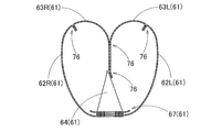
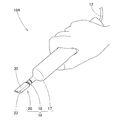
- FIG. 9 is a schematic cross-sectional view of an airbag made of an airbag base fabric to which an adhesive is applied in the embodiment, corresponding to the IX-IX portion of FIG. It is a schematic perspective view which shows the modification of the coating device of embodiment.
- a coating apparatus 10 used in the method for coating an adhesive includes a dispenser 11 capable of quantitatively supplying an adhesive
- the coating unit 15 includes a supply path 12 that supplies the adhesive from the dispenser 11 to the coating unit 15 side.
- the coating unit 15 includes a unit main body 16 and a coating operation unit 37.
- the application operation means 37 includes a holder 38 that can move up and down while holding the unit body 16, and a moving base 39 that moves the airbag fabric 61 (61 ⁇ / b> A, 61 ⁇ / b> B) set on the upper surface 39 a side in the movement direction SD. , And is configured.
- the unit main body 16 includes an applicator 20 that applies an adhesive to a predetermined reinforcing target surface 77 of the airbag base fabric 61, a needle-type supply support 18 that supports the applicator 20 so that the adhesive can be supplied, A cylinder-type storage unit 17 that stores the adhesive supplied from the dispenser 11 through the supply path 12 while assembling the supply support unit 18 is provided. Furthermore, the applicator 20 includes an application material 22 and a cover 30 that covers the application material.
- an airbag base fabric 61 to which an adhesive is applied by the coating apparatus 10 is, for example, a passenger seat airbag 60 mounted on an instrument panel in front of a passenger seat of a vehicle. Etc. are used.
- the airbag base fabric 61 includes left and right outer fabrics 62 (62L, 62R) on the outer peripheral wall of the airbag 60, inner fabric 63 (63L, 63R) on the front center side of the outer peripheral wall, and air A tether cloth 64 that is disposed in the bag 60 and restricts the front and rear dimensions of the airbag 60 in the inflated completed shape; the upper and lower tether cloths 65 and 65 that regulate the left and right dimensions in the inflated completed shape; It is composed of a plurality of reinforcing cloths 67 that enhance heat resistance.
- These airbag base fabrics 61 (61A, 61B, see FIGS. 1 and 6), to which an adhesive is applied to the sewing portion 76, are formed from a fabric having the following cover factor (hereinafter abbreviated as CF). Has been.
- CF NW x DW 0.5 + NF x DF 0.5 (1)
- NW Warp density (lines / in)
- DW Warp fineness (dtex)
- NF Weft density (main / in)
- DF Weft fineness (dtex)
- PA polyamide
- PA fiber examples include aliphatic polyamides such as nylon 66, nylon 6, nylon 46, and nylon 12; aromatic polyamides such as aramid.
- polyester fiber usually PET (polyethylene terephthalate) can be exemplified.
- the weaving aspect of the base fabric (fabric) 61 is usually a plain weave, it may be an oblique weave or a satin weave.
- the illustrated base fabric 61 is a plain weave.
- the base fabric 61 may be coated on one side even if it is not coated.
- the coating agent silicone, urethane, CR rubber or the like can be used.
- the illustrated base fabric 61 is coatless (see FIG. 6).
- the CF represented by the formula (1) in the base fabric (fabric) 61 is usually limited as long as it has a bending resistance that can secure a low air permeability necessary for an airbag and can be folded.
- CF is 1000 to 2700, preferably 1500 to 2500.
- the weight and cost of the airbag can be reduced. If the CF is too low, it is difficult to obtain a predetermined mechanical strength for the base fabric, particularly in the case of a coatless, and it is difficult to secure a low air permeability necessary for the airbag.
- the rigidity of the base fabric is difficult to be within a predetermined value, and when the yarn density is high, the fabric becomes thick, causing problems with the folding and storing properties of the airbag. It becomes easy and is not preferable.
- the sewing thread 74 a thread made of polyamide fiber or polyester fiber is usually used as in the case of the base fabric.
- the thickness of the sewing thread is 400 to 2600 dtex, preferably 1200 to 1900 dtex. If the sewing thread is thin, it is difficult to secure the sewing strength. On the other hand, if the sewing thread is thick, troubles such as breaking of the sewing needle or stopping of the sewing machine are likely to occur during sewing of the sewing machine when the package is raised or the airbag is manufactured. At that time, the number of moving parts is 2 to 5 needles / cm. In addition, when there are a plurality of moving parts, the distance between the moving parts is 2.5 to 10 mm.
- the adhesive 41 used in the embodiment has a viscosity of 10 to 500 mPa ⁇ s, and has a low viscosity that can be impregnated by capillary action in the coating material 22 formed by extruding a heat-fusible fiber. .
- the adhesive 41 an adhesive having adhesiveness (wetting property) on both the base fabric 61 (61A, 61B) and the sewing thread 74 is used.
- the form of the adhesive 41 is preferably a solvent-less emulsion from the viewpoints of handleability and environmental problems.
- the base resin in this emulsion is not particularly limited as long as both the base fabric and the sewing thread have adhesiveness (wetability) as described above.
- the base fabric is PET or PA, PA (nylon), ester Examples thereof include resins (polymers) such as those based on urethane, urethane, and epoxy.
- water-based polyether-modified urethane and carbonate-modified urethane having hydrolysis resistance are desirable from the viewpoint of coating film durability, and in particular, from the viewpoint of increasing sliding resistance, hydrolysis resistance, and productivity.
- Carbonate-modified urethane with a crosslinking agent added (short curing time) is desirable.
- the carbonate-modified urethane means a polyurethane having a polycarbonate chain or mainly.
- modified urethane does not include other modified urethane unless otherwise specified.
- these modified urethanes are usually those in which terminal COO- is blocked with amines such as triethylamine.
- the urethane-modified urethane (emulsion) containing a polycarbonate chain in the molecule of the present invention can be produced by a known production method. Specifically, for example, a polyol containing a polycarbonate chain (hereinafter referred to as polycarbonate polyol). ) And diisocyanate in a solvent, and then emulsified.
- polycarbonate polyol examples include compounds obtained by reacting glycols such as 1,4-butanediol, 1,6-hexanediol, diethylene glycol and the like with diphenyl carbonate and phosgene. These can be used alone or in combination of two or more.
- diisocyanate examples include 2,4-tolylene diisocyanate, 2,6-tolylene diisocyanate, m-phenylene diisocyanate, p-phenylene diisocyanate, 4,4′-diphenylmethane diisocyanate, 2,4′-diphenylmethane diisocyanate, 2,2 '-Diphenylmethane diisocyanate, 3,3'-dimethyl-4,4'-biphenylene diisocyanate, 3,3'-dichloro-4,4'-biphenylene diisocyanate, 1,5-naphthalene diisocyanate, 1,5-tetrahydronaphthalene diisocyanate, Tetramethylene diisocyanate, 1,6-hexamethylene diisocyanate, dodecamethylene diisocyanate, trimethylhexamethylene diisocyanate, 1,3-cyclohexylene diisocyanate Socyanate, 1,4-cyclo
- aliphatic diisocyanates are preferred from the viewpoints of stability and light resistance.
- the aliphatic diisocyanate among the diisocyanates listed above, those belonging to the aliphatic diisocyanate can be used as they are.
- the modified urethane can use the commercial item of an emulsion form normally.
- the crosslinking agent is not limited as long as it can undergo a condensation reaction with COO-.
- oxazoline and glycols, amino alcohols, and diamines having both hydroxyl groups and amino groups at both ends can be mentioned.
- At least one compound (hydrophilic organic compound I) selected from amino alcohols, dialkylamino alcohols and (poly) alkylene glycol monoalkyl ethers as described in JP 2011-132374 A is used.
- a carbodiimide compound (glycols) having a carbodiimide group that is more hydrophilic than the hydrophilic organic compound I and is sealed with a compound having at least one hydroxyl group is desirable.
- dicyclohexylmethane dicarbodiamide which is a polyalkylene (ethylene) oxide double-end adduct having a terminal blocked with an alkoxy group, as described in JP-A No. 2000-7642.
- the coating film has excellent durability (abrasion resistance, hydrolysis resistance, and reactivity).
- the resin cross-linking agent of the present invention has at least one compound selected from dialkylamino alcohol, hydroxycarboxylic acid alkyl ester, and (poly) alkylene glycol monoalkyl ether at the end of a carbodiimide compound having at least one carbodiimide group. It consists of a carbodiimide compound sealed with (hydrophilic organic compound I) and a compound having higher hydrophilicity than the hydrophilic organic compound I and having at least one hydroxyl group, and a hydratable liquid compound.
- At least one compound selected from dialkylamino alcohols, hydroxycarboxylic acid alkyl esters, and (poly) alkylene glycol monoalkyl ethers is sometimes referred to as “hydrophilic organic compound I”.
- the carbodiimide compound used in the present invention is preferably a carbodiimide compound in which the isocyanate terminal of the carbodiimide compound is sealed with a mixture of the hydrophilic organic compound I and an organic compound having a higher hydrophilicity than the hydrophilic organic compound I.
- Crosslinking agents Commercially available products can be used for these crosslinking agents.
- “Carbodilite” (registered trademark) series manufactured by Nissin Chemical Co., Ltd. can be mentioned.
- those having high reactivity (short curing time) such as “Carbodilite V-02-L2” can be preferably used from the viewpoint of productivity.
- the amount of the crosslinking agent added is 0.1 to 10 parts (preferably 1 to 5 parts) based on 100 parts of the modified urethane in terms of solid content. If the addition amount of the cross-linking agent is too small, it is difficult to ensure the adhesiveness to the sewing thread and the base fabric. Conversely, if it is excessive, the coating film becomes hard and the base fabric loses its flexibility.
- the “part” indicating the blending unit or the like is a mass unit unless otherwise specified.
- an antifoaming agent, a thickening agent, and the like may be appropriately added to the adhesive applied to the sewing portion from the viewpoint of applicability, and a secondary material such as a coloring agent may be added from the viewpoint of the appearance of application.
- the basic composition of the adhesive used in the embodiment is as follows.
- ⁇ Basic composition> Modified urethane (“Hydran WLS-210”, solid content 35%) 100 parts Cross-linking agent (“Carbodilite V-02-L2” solid content 40%) 3 parts Other additives (antifoaming agent, thickener, colorant) 2 parts
- the addition amount of the crosslinking agent in terms of solid content with respect to the modified urethane is 3.4 parts of the crosslinking agent with respect to 100 parts of the modified urethane.
- the physical properties of the crosslinking agent are pH 8 to 11, viscosity 100 mPa ⁇ s, NCN equivalent (chemical formula amount per mol of carbodiimide group) 385 (quoted from Nisshinbo Chemical website).
- the coating material 22 of the applicator 20 is formed from an extruded product 52 that is extruded by an extrusion molding machine 50.
- the extrusion molding machine 50 is a well-known machine (see the above-mentioned Patent Document 4), and a predetermined number of slit pieces 51 made of a long nonwoven fabric are introduced to form an extrusion-molded product 52.
- the slit piece 51 is made of a heat-fusible fiber 28a (see FIG. 3) in which PE, PET, PP, etc. having a wire diameter of 2 to 30 ⁇ m and a length of 2 to 300 mm are mixed, that is, a polyolefin fiber. It consists of a non-woven fabric (weighing 5 to 50 g / m 2 ), and is fed into the extruder 50 along the longitudinal direction of the slit piece 51.
- the extruded product 52 has a cross section with a porosity of 50 to 80%.
- the heat-fusible fibers are extruded so as to be aligned as much as possible along the extrusion direction PD.
- a non-woven fabric of heat-fusible fibers it is possible to fuse fibers without using an unnecessary adhesive, and it is easy to arrange the fibers along the longitudinal direction of the spunbond. Nonwoven fabric produced by the manufacturing method is desirable.
- the extruded product 52 has a width dimension W1 of 20 mm, a thickness dimension T of 6 mm (see FIG. 7), and a thickness dimension t (see FIG. 6) of 0 on the entire outer periphery.
- a skin layer 27 having a thickness of 1 to 0.3 ⁇ m is formed.
- the width dimension W1 is equal to the application width for applying the adhesive 41 to the sewing portion 76, that is, the width dimension W0 of the reinforcement target surface 77.
- the application side width dimension Wf (see FIG. 6) on one side centered on the sewing portion 76 is 5 mm or more from the viewpoint of reinforcement of the sewing portion 76. It is desirable to set.
- the upper limit of the coating side width dimension Wf is normally preferably 15 mm or less from the viewpoint of deterioration of touch and resource saving, and the coating material 22 may be set to the width dimension W1 corresponding to this coating width.
- the coating material 22 is formed by providing an inclined coating surface 25 at the tip after the extruded product 52 is cut into a cut piece 53 having a predetermined length.
- the application surface 25 has a width dimension W1 corresponding to the width dimension W0 of the reinforcement target surface 77, and intersects the axial direction CD of the application material 22 (that is, coincides with the extrusion direction PD of the extruded product 52).
- the flat surface is formed by cutting the entire cross section of the coating material 22 at an angle ⁇ (see FIGS. 3 and 7).
- the leading edge (front edge) 26a and the base portion side edge (rear edge) 26b are both disposed along the width direction CW of the coating material 22, and the coating surface 25 has an intersection angle ⁇ of 45 °. Is formed.
- the coated surface 25 is formed from a cut surface that is cut by a Thomson blade or the like that is not heated so that the cut surface does not melt at the time of cutting, and a solidified portion made of a skin layer 27 is formed on the outer peripheral edge 26. 27a is formed, and on the inner side surrounded by the solidified portion 27a, the end 28b of each fiber 28a of the fiber layer 28 is exposed.
- the crossing angle ⁇ corresponds to the angle between the reinforcement target surface 77 of the sewing portion 76 and the axial direction CD of the coating material 22 because substantially the entire coating surface 25 is applied to the sewing portion 76 during application.
- the movement direction SD of the movable table 39 is the obtuse angle direction opposite to the acute intersection angle ⁇ along the reinforcement target surface 77, and therefore, the sewing portion on the application surface 25.
- the relative movement direction MD with respect to 76 is the direction on the crossing angle ⁇ side.
- the cover 30 that covers the coating material 22 is made of metal such as an aluminum plate or a steel plate that is more rigid than the coating material 22 and has a substantially rectangular tube shape that covers the outer peripheral surface 23 of the coating material 22.
- the cover 30 includes a ceiling wall portion 31 that covers the upper surface 23 a of the coating material 22, a bottom wall portion 34 that covers the lower surface 23 b, and side wall portions 35 and 35 that cover both side surfaces 23 c and 23 c of the coating material 22. It is configured.
- the cover 30 is configured to cover the entire outer peripheral surface 23 on the side of the base portion 22b away from the tip portion 22a provided with the application surface 25 of the application material 22, and is in close contact with the outer peripheral surface 23 of the application material 22.
- the dimension is set such that the base portion 22b side is inserted so that the coating material 22 can be prevented from being deformed.
- the ceiling wall portion 31 includes a tip support portion 32 that extends so as to approach the tip edge 26a of the coating material 22 and has an edge 32a that is parallel to the tip edge 26a except for the concave portion 33.
- the tip support portion 32 is in contact with the upper surface 23a of the triangular portion 22at having a triangular prism shape in section just above the coating surface 25 in the coating material 22, and supports the upward deformation of the triangular portion 22at during the coating operation. It becomes a part to do.
- the tip support part 32 includes a recess 33 that exposes a part of the upper surface 23a of the triangular prism-shaped part (triangular part) 22at in the center in the width direction CW at the edge 32a on the tip side.
- the recess 33 is formed so as to expand into a tapered triangular shape over the end edge 32a.
- the supply support portion 18 is provided with a needle portion 18a in the shape of a circular thin injection needle capable of supplying the adhesive 41 to the coating material 22 side at the tip, and the connection port portion 17b of the storage portion 17 on the base portion side.
- the nipple portion 18b is connected to the nipple portion 18b.
- the supply support unit 18 supports the coating material 22 so that the adhesive 41 can be supplied to the coating material 22 by inserting the needle portion 18a into the base portion side end surface 24 of the coating material 22 covered with the cover 30.
- the applicator 20 (applicator 22) can be easily removed from the supply support 18 by simply pulling it out of the needle 18a, and then another applicator 20 is attached to the supply support 18.
- the new application tool 20 can be easily attached to the supply support part 18, and the application tool 20 can be replaced. It is comprised so that it can perform easily.
- the storage portion 17 includes a connection port portion 17b for assembling the nipple portion 18b of the supply support portion 18 at the front end of the housing 17a in which the adhesive 41 is stored, and the adhesive 41 supplied from the dispenser 11 is provided on the end surface of the housing 17a.
- An inflow port portion 17c for connecting the supply path 12 is disposed so as to allow inflow.
- the dispenser 11 is a known one, and is configured so that a predetermined amount of the adhesive 41 can be supplied at a predetermined discharge pressure.
- the base fabrics 61A and 61B are sewn below the application surface 25 of the application material 22 arranged above the movable table 39.
- the base cloth 61 ⁇ / b> A and 61 ⁇ / b> B are set on the moving table 39 by arranging the portion 76 and matching the sewing line SL of the sewing unit 76 in accordance with the moving direction SD of the moving table 39.
- the axial direction CD of the coating material 22 overlaps with the sewing line SL above the sewing line SL of the sewing portion 76, and the width direction CW of the coating material 22 is arranged orthogonal to the sewing line SL. (See FIG. 2).
- the application material 22 is disposed above the sewing portion 76 so that the width direction CW thereof coincides with the width direction FW of the reinforcement target surface 77 on which the adhesive 41 is applied to the sewing portion 76.
- the application surface 25 is arranged in parallel with the reinforcement target surface 77.
- the holder 38 as the application operation means 37 is lowered to apply the entire surface of the application surface 25 of the application material 22 to the sewing portion 76 with a constant load, and a predetermined amount of adhesive 41 is supplied from the dispenser 11 to the storage portion 17.
- the moving table 39 as the application operation means 37 is moved at a constant speed in the movement direction SD, the adhesive 41 is applied to the reinforcement target surface 77 of the sewing portion 76, and the application operation is performed. .
- the supply of the adhesive 41 from the dispenser 11 to the storage portion 17 is stopped, the holder 38 is raised, and the application surface 25 of the application material 22 is formed on the base fabric. While moving away from 61A and 61B, the movement of the movable table 39 is stopped, and preparation for the next adhesive 41 application operation is performed.
- the heating means may be normal hot air heating, microwave heating or the like, but heating means such as infrared (IR) capable of local heating is desirable. This is because energy saving is achieved and the curing process can be easily performed in synchronization with the sewing process for forming the sewing portion 76 and the application process for applying the adhesive 41.
- IR infrared
- the width of the coating surface 25 at the tip of the coating material 22 is matched with the width direction CW so that the width direction FW of the surface to be reinforced 77 is matched.
- the substantially entire surface is applied to the surface to be reinforced 77 with a constant load, and the side in which the axial direction CD of the coating material 22 is set to an acute angle ⁇ with respect to the surface to be reinforced 77 is the moving direction MD of the coating surface 25 with respect to the sewing portion 76.
- the coating material or the airbag base fabric (in the case of the embodiment, the base fabric 61 side) is moved at a constant speed along the sewing line SL of the sewing portion 76, the coating material 22 is impregnated.
- the adhesive 41 that has been applied is applied to the surface to be reinforced 77 with a predetermined width dimension W0 (W1).
- the coating surface 25 of the coating material 22 is surrounded by the solidified portion 27 a of the skin layer 27 around the outer peripheral edge 26, and the fiber layer 28 is disposed inside the solidified portion 27 a.
- the bundles of the ends (end surfaces) 28b of the heat-fusible fibers 28a arranged so as to be aligned along the axial direction CD of the coating material 22 are arranged. Therefore, the end 28b of the heat-fusible fiber 28a arranged in a brush shape is slightly bent by the movement in the movement direction MD side with respect to the sewing portion 76, and uses the outer peripheral surface and the end surface to the solidified portion 27a.
- the adhesive 41 impregnated between the fibers 28a is applied to the surface to be reinforced 77 so as to be brushed with a fine brush (see the application concept illustration in FIG. 3). ).
- the application surface 25 is moved such that the side in which the axial direction CD of the application material 22 is set to an acute angle ⁇ with respect to the reinforcement target surface 77 is the movement direction MD side with respect to the sewing portion 76.
- the end 28b of the heat-fusible fiber 28a and the solidified portion 27a around the end of the heat-fusible fiber 28a are not slightly deformed so as to bend, and are slightly bent to the forward side in the moving direction MD and the backward side in the reverse direction SD.
- the adhesive 41 is applied to the reinforcement target surface 77 with the width dimension W1 of the application surface 25, and the edges (parting) of both edges are clarified with a uniform thickness with high accuracy. And is applied with a predetermined width dimension W1.
- the outer peripheral surface side of the coating material 22 excluding the coating surface 25 is covered with the skin layer 27, and the adhesive 41 impregnated in the coating material 22 is hard to evaporate, that is, hard to be cured. Since the impregnated state is maintained, clogging of the adhesive 41 at the site of the coating material 22 is suppressed, and the adhesive 41 is applied to the reinforcement target surface 77 of the predetermined airbag base fabric 61A, 61B. After the coating, the coating material 22 can be kept in the air without replacement until the transition to the reinforcement target surface 77 of the next airbag fabric 61A, 61B. Can be done efficiently.
- the application method of the adhesive 41 to the sewing part 76 and the application apparatus 10 that implements the method according to the embodiment it is easy to apply the reinforcing adhesive 41 to the sewing part 76 of the airbag base fabric 61.
- the application width W0 can be accurately and clearly defined and applied, and the adhesive 41 can be applied efficiently.
- the adhesive 41 applied to the sewing portion 76 is applied to the reinforcement target surface 77 with an application width W0 in a state in which a 20 mm boundary corresponding to the width dimension W1 of the application material 22 is clarified.
- the sewing portion 76 can be suitably reinforced.
- the application surface 25 is set such that the crossing angle ⁇ with respect to the axial direction of the coating material 22 is 45 ° within a range of 45 to 60 °.
- the application surface 25 having a predetermined dimension can be easily obtained, and the adhesive 41 can be applied with durability.
- the coating surface 25 in the process of forming the coating material 22 from the extruded product 52 is cut.
- the edges 26a that are perpendicular to the width direction CW of the coating material 22, that is, the opposite edges 26a along the moving direction MD of the coating material 22 during coating. , 26b it is easy to remain for a long time, and it becomes difficult to create the coating surface 25, which is not preferable.
- the airbag fabric 61 of the coating material 22 itself is compared to the case of 60 ° or less.
- the force in the direction of shrinking the fibers 28a It becomes easy to act, causing a phenomenon that each fiber 28a is buckled, and the flow path through which the impregnated adhesive 41 flows to the reinforcement target surface 77 side is easily blocked, resulting in curing. This is not preferable.
- the terminal 28b of each heat-fusible fiber exposed to the coating surface 25 is applied at the time of coating. It is possible to bend the coating material 22 in the direction SD and the direction SD opposite to the movement direction MD with substantially the same gap therebetween, and to prevent the flow of the impregnated adhesive 41 flowing to the reinforcement target surface 77 side from being blocked. Can be applied with durability.
- the application surface 25 of the application material 22 is set so that the crossing angle ⁇ with respect to the axial direction CD of the application material 22 is set within a range of 45 to 60 °, which is wider than 45 ° in the embodiment. May be.
- the application amount applied to the reinforcement target surface 77 by the application surface 25 of the application material 22 is the same, and the dispenser is equivalent. It was proved that the coating material 22 can accurately apply the adhesive 41 to the surface to be reinforced 77 in accordance with the supply amount of the adhesive 41 from 11.
- a cover 30 that is more rigid than the coating material 22 and covers the coating material 22 is disposed on the outer peripheral side of the coating material 22, and the cover 30 is applied to the coating surface 25 of the coating material 22.
- a tip support portion 32 capable of supporting the upper surface 23a of the triangular prism-shaped part (triangular part) 22at directly above.
- the distal end portion 22a provided with the application surface 25 of the coating material 22 is supported by the distal end support portion 32 of the cover 30 that is more rigid than the coating material 22, and thus the distal end portion 22a.
- the coating material 22 is bent so as to be lifted away from the reinforcement target surface 77 on the side opposite to the moving direction MD of the coating material 22. Therefore, the entire application surface 25 can be applied to the reinforcement target surface 77 stably, and a predetermined amount of the adhesive 41 can be applied stably to the reinforcement target surface 77.
- the cover 30 is configured in a cylindrical shape so as to be in close contact with and cover the entire outer peripheral surface 23 of the coating material 22, and not only the vicinity of the distal end portion 22 a but also the entire coating material 22. It can be protected by the cover 30, can be suitably prevented from losing its shape, and can contribute to improving the durability of the coating material 22.
- the tip support portion 32 of the cover 30 has a recess 33 that exposes a part of the upper surface 23a of the triangular prism-shaped portion 22at in the center in the width direction CW on the tip (edge) 32a side. It is prepared for.
- the durability of the application surface 25 of the application material 22 is further increased. Can be improved. That is, the application surface 25 of the application material 22 is applied to the reinforcement target surface 77 to apply the adhesive 41 to the reinforcement target surface 77, and the airbag base fabric is applied to the sewing portion 76 of the reinforcement target surface 77.
- a sewing thread 74 that sews 61A and 61B protrudes see FIG. 5
- the portion of the application surface 25 at a position corresponding to the sewing portion 76 rises toward the tip support portion 32. Become.
- the concave portion 33 is disposed above the portion, the amount of displacement rising in the concave portion 33 can be stored. Therefore, even if the coating material 22 is formed from the extruded product 52 having the same cross-sectional shape along the axial direction CD, the protruding portion of the sewing thread 74 can be smoothly deformed. Therefore, it is possible to maintain the stable shape of the application surface 25 and to improve the durability of the application surface 25.
- the concave portion 33 is limited to a triangular shape as in the embodiment as long as the concave portion 33 is disposed in the vicinity of the triangular portion 22at of the tip portion 22a of the coating material 22 and above the portion that contacts the sewing portion 76 of the coating surface 25. Instead, a semicircular recess may be used. Moreover, as long as it is above the site
- the coating material 22 since the coating material 22 is detachably supported with respect to the supply support portion 18, the coating material 22 can be easily replaced, and the efficiency of the coating work can be improved. It can contribute to improvement. Therefore, for example, during application work, when the adhesive 41 is blurred due to clogging of the adhesive 41, deformation of the application surface 25, or the like, or before the timing at which such a phenomenon occurs, The coating material 22 can be easily replaced for every 20, which is preferable.
- the supply support unit 18 is configured to support the coating material 22 by inserting the single needle portion 18a into the coating material 22, but the supply support unit 18 has a thin injection needle shape capable of supplying the adhesive 41.
- a plurality of needle portions may be provided in parallel along the width direction CW of the coating material 22, and the plurality of needle portions may be inserted into the coating material 22 to support the coating material 22 easily.
- the coating material 22 is supported by a plurality of thin needle portions as described above, there is a possibility that the adhesive 41 is clogged in each needle portion.
- a configuration in which one needle portion 18a is inserted to support the coating material 22 is preferable.
- the base portion 22b side of the coating material 22 is arranged as shown in parentheses in FIG. It is good also as the supply support part 19 which provided the fitting part 19a which fits.
- an engagement portion that can be clipped corresponding to the cover 30 is formed so as to be replaceable. You may comprise so that it can support. Further, such supply support portions 18 and 19 may be configured separately from the storage portion 17 or may be configured integrally with the storage portion 17.
- the single thread sewing by the sewing thread 74 is exemplified, but also when the adhesive 41 is applied to the sewing portion by two or more sewings.
- the coating method and the coating apparatus of the present invention may be used.
- the moving base 39 as the application operation means 37 is operated to move only the airbag base fabric 61A, 61B side at a constant speed.
- the holder 38 that can press the application surface 25 against the reinforcement target surface 77 with a constant load is moved to move only the application material 22 side, or the holding means for holding the unit main body 16 as the application operation means 37.
- the movable base 39 as the base cloth set side means for setting the base cloth 61 side as the coating operation means 37 are operated together to apply the coating material 22 side and the airbag base cloths 61A and 61B. You may move both sides.
- the coating apparatus 10A may be configured as a handy type.
- the coating apparatus 10 ⁇ / b> A is configured such that the adhesive 41 from the dispenser 11 capable of supplying a constant amount of the adhesive 41 is supplied to the storage unit 17 via the supply path 12.
- the dimensional shape of the coating material 22 is exemplified by the width dimension W1 of 20 mm and the thickness dimension T of 6 mm.
- the width dimension W1 is preferably in the range of 5 mm to 15 mm as the coating side width dimension Wf, and is preferably in the range of 10 to 30 mm, which is about twice that.
- the thickness T of the coating material 22 is preferably within a range of 4 to 15 mm.
- Extruder 52 ... Extrusion product, 61 (61A, 61B) ... Base fabric for airbag, 71 ... Warp, 72 ... Weft, 74 ... Sewing thread, 76 ... Sewing part, 77 ... Surface to be reinforced, SL ... sewing line, PD ... extrusion direction (extruded product), CD ... axial direction of application material, FW ... width direction of reinforcement target surface, CW ... width direction of application material, WO ... The width dimension of the surface to be reinforced, W1... (Width of the coating material), MD...
Landscapes
- Engineering & Computer Science (AREA)
- Chemical & Material Sciences (AREA)
- Organic Chemistry (AREA)
- Life Sciences & Earth Sciences (AREA)
- Wood Science & Technology (AREA)
- Textile Engineering (AREA)
- Mechanical Engineering (AREA)
- Coating Apparatus (AREA)
- Air Bags (AREA)
- Application Of Or Painting With Fluid Materials (AREA)
- Adhesives Or Adhesive Processes (AREA)
- Chemical Or Physical Treatment Of Fibers (AREA)
Abstract
経糸と緯糸とを織ってなるエアバッグ用基布(61A,61B)を縫製した縫製部(76)に対し、接着剤(41)を毛細管現象を利用して含浸させた塗布材(22)の先端の塗布面(25)を当てて、補強用の接着剤(41)を塗布する。塗布材は、熱融着性繊維(28a)を押出方向に揃えて押出成形された押出成形品から、外周面のスキン層(27)を残して、斜めの塗布面(25)を設けて形成される。塗布時には、塗布材の塗布面の略全面を、幅方向を対応させて、縫製部の補強対象面(77)に当てるとともに、塗布材の軸方向(CD)を補強対象面に対して鋭角の角度(θ)とさせる側を、塗布面の縫製部に対する移動方向(MD)側として、エアバッグ用基布を移動させて、接着剤を塗布する。
Description
本発明は、経糸と緯糸とを織ってなるエアバッグ用基布を縫製した縫製部に対し、補強用の接着剤を塗布する縫製部への接着剤の塗布方法と塗布装置に関する。
従来、経糸と緯糸とを織ってなるエアバッグ用基布を縫製した縫製部に対して、ガス抜けを抑える等の補強のために、接着剤やシール材を塗布することが知られている(例えば、特許文献1参照)。また、縫製部を形成する2枚のエアバッグ用基布の間に、予め、接着剤を塗布しておいて、縫製し、その縫製部を補強する場合もあった(例えば、特許文献2参照)。さらに、縫製部ではないものの、エアバッグ用基布を縫製を利用せずに接着剤を塗布して、基布相互を接合させるものもあった(例えば、特許文献3参照)。
これらの接着剤やシール材等の粘度のある材料の塗布には、ナイフコート、ロールコート、刷け塗り等により行なわれていた。さらに、特許文献2,3の場合には、接着剤は、スプレー塗布、転写ローラを使用するローラ塗布、刷け塗り等によって、所定部位に塗布されていた。
なお、粘度の低いインク等の塗布には、不織布や繊維成形体等からなるペン先に、塗布材料を含浸させておき、そのペン先を、塗布する処理面に当てて移動させて塗布する塗布方法もあった。このようなペン先は、熱融着性繊維を押出方向に揃えて押出成形した押出成形品から形成されていた(例えば、特許文献4参照)。
しかし、エアバッグ用基布の縫製部に対し、ガス抜け対策のための縫目における織糸ずれの防止を図るための補強用として、接着剤を塗布する際、塗布後の接着剤の硬化により硬くなるエリアが広がれば、縫製後の製品としてのエアバッグを所定の収納部位に折り畳んで収納する際に、コンパクトに折り畳めない、あるいは、エアバッグ自体の縫製部の感触の悪化を招くことから、好ましくなく、厳格な塗布幅で塗布する必要が生ずる。
そのため、非接触のスプレー塗布では、霧状に接着剤を飛散させて縫製部に塗布するものであり、塗布されたエリアの境界を明確に規定し難く、マスキング等の対策が必要となり、簡便に、厳格な塗布幅で塗布する点で、課題がある。
また、接触させて塗布するロール転写や刷け塗りでは、ある程度の塗布幅で接着剤を塗布できるものの、塗布作業中における塗布前に、接着剤が大気中に曝され易く、硬化して、つぎの縫製部への塗布作業に支障を生じてしまう。
同様に、例えば、接着剤を含浸させたフェルトペン等の塗布具のペン先を、縫製部に当てて塗布するようにしても、接着剤が硬化し易ければ、ペン先や塗布具を取替える必要が生じ、塗布作業の効率を悪化させてしまう。
本発明は、上述の課題を解決するものであり、エアバッグ用基布の縫製部に補強用の接着剤を塗布する際、簡便に、塗布幅を正確かつ明瞭に規定して塗布できるとともに、作業効率よく接着剤を塗布できる縫製部への接着剤の塗布方法と塗布装置を提供することを目的とする。
本発明に係る塗布方法は、経糸と緯糸とを織ってなるエアバッグ用基布を縫製した縫製部を配設させた補強対象面に対し、塗布材に含浸させた接着剤を塗布する下記工程の塗布工程、を備えた縫製部への接着剤の塗布方法である。前記塗布材は、押出成形品を、前記塗布材の軸方向と交差する交差角度として、切断するとともに、前記押出成形品の断面の全域で切断した平面状の切断面を形成しつつ、所定長さに切断して形成される。前記押出成形品は、熱融着性繊維を押出方向に揃えるとともに、押出方向を前記塗布材の軸方向に配置させ、かつ、前記補強対象面の幅寸法に対応する幅寸法とし、さらに、外周面にスキン層を残して、押出成形して、形成される。前記塗布工程では、前記塗布材に、前記接着剤を毛細管現象を利用して含浸させ、前記塗布材の前記切断面を塗布面として、該塗布面の略全面を、幅方向を対応させて、前記補強対象面に当てるとともに、前記塗布材の軸方向を前記補強対象面に対して鋭角とさせる側を、前記塗布面の前記縫製部に対する移動方向側として、前記塗布材若しくは前記エアバッグ用基布の少なくとも一方を移動させて、前記接着剤を前記補強対象面に塗布する。
本発明に係る塗布方法では、塗布材の先端における塗布面の略全面を、幅方向を対応させて、補強対象面に当てるとともに、塗布材の軸方向を補強対象面に対して鋭角とさせる側を、塗布面の縫製部に対する移動方向側として、縫製部の縫製ラインに沿って、塗布材若しくはエアバッグ用基布の少なくとも一方を移動させれば、塗布材に含浸されていた接着剤が、所定の幅寸法で、補強対象面に塗布されることとなる。
その際、塗布材の塗布面は、外周縁をスキン層の固化部で囲まれて、その固化部の内側に、塗布材の軸方向に沿って揃えられたように配設されている熱融着性繊維の端末の束が、配置された状態となっている。すなわち、刷毛状に配置された熱融着性繊維が、固化部に位置規制された状態で、繊維間に含浸されていた接着剤を、微小な刷毛で刷け塗りするように、補強対象面に塗布する状態となる。
そしてさらに、塗布面は、塗布材の軸方向を補強対象面に対して鋭角とさせる側を、縫製部に対する移動方向側として、移動させており、塗布面における熱融着性繊維の端末やその周囲の固化部は、移動方向の前進側と逆方向の後退側に、若干、曲がるものの、塗布材の幅方向に張り出すことが抑制される。そのため、接着剤は、塗布面の幅寸法で補強対象面に対して塗布されることとなって、均一の厚さで、精度よく、両縁のエッジ(見切り)を明確にして、所定の幅寸法で塗布される。
また、塗布材は、塗布面を除いた外周面側がスキン層に覆われており、塗布材に含浸した接着剤は、蒸発し難く、すなわち、硬化し難い状態で塗布材内に含浸された状態を維持することから、塗布材の部位での接着剤の詰まりが抑制されて、所定のエアバッグ用基布の補強対象面に対して接着剤を塗布した後、つぎのエアバッグ用基布の補強対象面に移行するまで、交換等せずに、塗布材を空中に待機させておくことができ、塗布作業を簡便かつ効率的に行うことができる。
したがって、本発明に係る縫製部への接着剤の塗布方法では、エアバッグ用基布の縫製部に補強用の接着剤を塗布する際、塗布幅を正確かつ明瞭に規定して塗布できるとともに、作業効率よく接着剤を塗布できる。
そして、本発明に係る塗布方法では、前記塗布面が、前記塗布材の軸方向に対する前記交差角度を、45~60°の範囲内として設定されていることが望ましい。
すなわち、塗布材の塗布面における塗布材の軸方向に対する交差角度が、45°未満であれば、塗布材を押出成形品から形成する工程での塗布面を切断加工して形成する際、スキン層を奇麗に切断し難く、特に、塗布材の幅方向と直交する縁、すなわち、塗布時の塗布材の移動方向に沿って対向する両縁側で、長く残り易くなって、塗布面を作成し難くなり、好ましくない。
また、塗布材の塗布面における塗布材の軸方向に対する交差角度が、60°を超えれば、60°以下の場合と比べて、塗布材自体のエアバッグ用基布への押圧力が同じとしても、塗布面に露出している各熱融着性繊維に対し、それらの繊維に沿う方向の力、換言すれば、各繊維を縮める方向の力、が作用し易くなって、各繊維が座屈する現象を招き、含浸させた接着剤を補強対象面側に流す流路が塞がり易くなって、硬化を招く等して、塗布時の耐久性を低下させてしまい、好ましくない。ちなみに、塗布材の塗布面における塗布材の軸方向に対する交差角度が、60°以下であれば、塗布面に露出させた各融着性繊維の端末が、塗布時の塗布材の移動方向と逆方向側に、相互の隙間を略同等として、曲がることが可能となり、含浸させた接着剤を補強対象面側に流す流路を塞ぐことを抑制できて、耐久性を持って、塗布することができる。
そのため、塗布材の塗布面は、塗布材の軸方向に対する交差角度を、45~60°の範囲内として設定されていることが望ましい。
そしてさらに、本発明に係る塗布方法では、前記塗布材が、前記塗布面から離れた元部側で、前記接着剤を定量供給可能なディスペンサから供給される前記接着剤を貯留させた貯留部と、接続されていることが望ましい。
このような構成では、塗布材の塗布面から補強対象面に塗布された接着剤の塗布量に応じて、塗布材に対し、貯留部を介して、ディスペンサからの接着剤を供給できることから、補強対象面に対して、一定量の接着剤を塗布でき、所定幅に塗布できることと相俟って、安定した接着剤の塗布量により、接着性能を向上させることに寄与できる。
本発明に係る塗布装置は、経糸と緯糸とを織ってなるエアバッグ用基布を縫製した縫製部を配設させた補強対象面に対し、塗布材に含浸させた補強用接着剤を塗布する塗布装置であり、前記塗布材と、前記接着剤を貯留した貯留部と、前記塗布材へ前記接着剤を供給可能に、前記塗布材を支持して前記貯留部に対して組み付ける供給支持部と、を備える。前記塗布材は、押出成形品を、前記塗布材の軸方向と交差する交差角度として、切断するとともに、前記押出成形品の断面の全域で切断した平面状の切断面を形成しつつ、所定長さに切断して形成される。前記押出成形品は、熱融着性繊維を押出方向に揃えるとともに、押出方向を前記塗布材の軸方向に配置させ、かつ、前記補強対象面の幅寸法に対応する幅寸法とし、さらに、外周面にスキン層を残して、押出成形して、形成される。そして、前記塗布材は、先端に塗布面を配置させて、該塗布面を前記補強対象面に当てて、前記塗布材若しくは前記エアバッグ用基布の少なくとも一方を移動させて、前記接着剤を前記補強対象面に塗布するように配設される。前記塗布材の塗布面は、外周縁に前記スキン層の固化部を有し、かつ、前記補強対象面の幅寸法に対応する幅寸法を維持して、前記塗布材の軸方向と交差する交差角度を有した平面状の切断面、から構成されている。
本発明に係る塗布装置では、塗布材の先端における塗布面の略全面を、幅方向を対応させて、補強対象面に当てるとともに、塗布材の軸方向を補強対象面に対して鋭角とさせる側を、塗布面の縫製部に対する移動方向側として、縫製部の縫製ラインに沿って、塗布材若しくはエアバッグ用基布の少なくとも一方を移動させれば、塗布材に含浸されていた接着剤が、所定の幅寸法で、補強対象面に塗布されることとなって、既述の本発明に係る塗布方法を実施することができ、エアバッグ用基布の縫製部に補強用の接着剤を塗布する際、簡便に、塗布幅を正確かつ明瞭に規定して塗布できるとともに、作業効率よく接着剤を塗布できる。
そして、本発明に係る塗布装置でも、前記塗布面が、前記塗布材の軸方向に対する前記交差角度を、45~60°の範囲内として設定されていれば、既述したように、スキン層の切断処理が容易となって、所定寸法の切断面を容易に形成できるとともに、耐久性を持って、塗布作業を行うことができる。
また、本発明に係る塗布装置では、前記塗布材の外周側に、前記塗布材より剛性を有して前記塗布材を覆うカバーが配設され、
前記カバーが、前記塗布材における前記塗布面の直上の断面三角柱状部位の上面を支持可能な先端支持部、を備えて構成されていることが望ましい。
前記カバーが、前記塗布材における前記塗布面の直上の断面三角柱状部位の上面を支持可能な先端支持部、を備えて構成されていることが望ましい。
このような構成では、塗布材の塗布面を設けた先端部が、塗布材より剛性を有したカバーの先端支持部により支持されることから、先端部が、塗布材の移動方向と逆方向側で、補強対象面から離れて浮き上がるように曲がることが抑制される。そのため、塗布面は、その全面を安定して補強対象面に当てることができ、安定して、所定量の接着剤を補強対象面に塗布することができる。
この場合、前記カバーの前記先端支持部が、先端側における幅方向の中央に、断面三角柱状部位の上面の一部を露出させる凹部、を備えて構成されていることが望ましい。
このような構成では、カバーの先端支持部の凹部を、補強対象面の縫製部に一致させて、塗布作業を行えば、塗布材の塗布面の耐久性を、一層、向上させることができる。すなわち、塗布材の塗布面は、補強対象面に当てられて、接着剤を補強対象面に塗布するが、その補強対象面の縫製部には、エアバッグ用基布を縫製した縫糸が出っ張っており、その縫糸の出っ張り分、縫製部に対応する位置の塗布面の部位が、先端支持部側に上昇することとなる。その際、その部位の上方に凹部が配設されていれば、その凹部で上昇する変位分を収納することができる。そのため、塗布材が、軸方向に沿った同一断面形状の押出成形品から形成されていても、縫糸の突出分、円滑に変形することができて、塗布材は、部分的に圧縮変形されることを抑制されて、安定した塗布面の形状を維持でき、塗布面の耐久性を向上させることができる。
そしてまた、本発明に係る塗布装置では、前記塗布材が、前記供給支持部に対して、取り外し可能に支持されていれば、塗布材を容易に交換することができて、塗布作業の効率向上に寄与できる。そのため、例えば、塗布作業時、接着剤の詰まりや塗布面の変形等により接着剤のかすれ等が発生した際、あるいは、そのような現象の発生するようなタイミングの前に、塗布材を容易に交換することができて、好適となる。
また、本発明に係る塗布装置では、前記貯留部が、前記接着剤を定量供給可能なディスペンサと接続されていることが望ましい。
このような構成では、既述したように、塗布材の塗布面から補強対象面に塗布された接着剤の塗布量に応じて、塗布材に対し、貯留部を介して、ディスペンサからの接着剤を供給できることから、補強対象面に対して、一定量の接着剤を塗布でき、所定幅に塗布できることと相俟って、安定した接着剤の塗布量により、接着性能を向上させることに寄与できる。
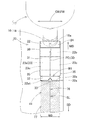
以下、本発明の一実施形態を図面に基づいて説明すると、実施形態の接着剤の塗布方法に使用する塗布装置10は、図1に示すように、接着剤を定量供給可能なディスペンサ11と、塗布ユニット15と、ディスペンサ11からの接着剤を塗布ユニット15側に供給する供給路12と、を備えて構成されている。塗布ユニット15は、ユニット本体16と、塗布動作手段37と、を備えて構成されている。塗布動作手段37は、ユニット本体16を保持して昇降可能なホルダ38と、上面39a側にセットしたエアバッグ用基布61(61A,61B)を移動方向SDに向けて移動させる移動台39と、を備えて構成されている。
ユニット本体16は、エアバッグ用基布61の所定の補強対象面77に接着剤を塗布する塗布具20と、接着剤を供給可能に塗布具20を支持するニードルタイプの供給支持部18と、供給支持部18を組み付けるとともに供給路12を経てディスペンサ11から供給される接着剤を貯留するシリンダタイプの貯留部17と、を備えて構成されている。さらに、塗布具20は、塗布材22と、塗布材を覆うカバー30と、を備えて構成されている。
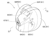
この塗布装置10により接着剤を塗布されるエアバッグ用基布61は、図8,9に示すように、例えば、車両の助手席前方のインストルメントパネルに搭載される助手席用のエアバッグ60等に使用されるものである。このエアバッグ60の場合、エアバッグ用基布61は、エアバッグ60の外周壁の左右の外側布62(62L,62R)、外周壁の前中央側の内側布63(63L,63R)、エアバッグ60内に配設されてエアバッグ60の膨張完了形状における前後の寸法を規制するテザー用布64、膨張完了形状における左右の寸法を規制する上下二段のテザー用布65,65、及び、耐熱性を高める複数枚の補強布67、から構成されている。
そして、縫製部76に接着剤を塗布されるこれらのエアバッグ用基布61(61A,61B、図1,6参照)は、つぎのようなカバーファクター(以下、CFと略す)の織物から形成されている。
なお、CFは、下記式(1)で求められる。
CF=NW × DW0.5 + NF × DF0.5 (1)
但し、NW:経糸密度(本/in)、DW:経糸繊度(dtex)
NF:緯糸密度(本/in)、DF:緯糸繊度(dtex)
そして、基布61は、通常、多用されているポリアミド(PA)繊維やポリエステル繊維のフィラメントで織製したものが使用されている。
但し、NW:経糸密度(本/in)、DW:経糸繊度(dtex)
NF:緯糸密度(本/in)、DF:緯糸繊度(dtex)
そして、基布61は、通常、多用されているポリアミド(PA)繊維やポリエステル繊維のフィラメントで織製したものが使用されている。
なお、上記PA繊維としては、例えば、ナイロン66、ナイロン6、ナイロン46、ナイロン12などの脂肪族ポリアミド;アラミドなどの芳香族ポリアミド等が例示できる。
また、上記ポリエステル繊維としては、通常、PET(ポリエチレンテレフタレート)等が例示できる。
なお、基布(布帛)61の織成態様は、通常、平織りとするが、斜文織りや朱子織りでもよい。図例の基布61は、平織りのものである。
また、基布61はコートレスでなくても片面がコートされていてもよい。そのコート剤としては、シリコーン、ウレタン、CRゴム等を使用可能である。図例の基布61は、コートレスとしている(図6参照)。
さらに、基布(布帛)61における前記式(1)で示されるCFは、通常、エアバッグに必要な低通気度を確保でき、かつ、折り畳み等が可能な剛軟度を有すれば特に限定されない。例えば、CFは、1000~2700、望ましくは1500~2500とする。CFの低い、即ち、高通気度の布帛を用いることにより、エアバッグの軽量化、低コスト化が可能となる。CFが低すぎると、基布に、特に、コートレスの場合、所定の機械的強度を得難くなるとともにエアバッグに必要な低通気度を確保し難くなる。
さらにまた、糸密度及び/又は繊度が高いと、基布の剛性が所定値内に収まり難く、さらに、糸密度が高い場合布帛が厚くなって、エアバッグの折畳み性・収納性に問題が生じ易くなり、好ましくない。
また、縫糸74としては、通常、基布と同様、ポリアミド繊維やポリエステル繊維からなる糸を用いる。縫糸の太さは、400~2600dtex、望ましくは、1200~1900dtexとする。なお、縫糸が細いと、縫製強度を確保し難い。逆に、縫糸が太いと、パッケージのアップやエアバッグ製造に際してのミシン縫製時にミシン針が折れる、ミシンが止まる等のトラブルが発生し易い。そのときの運針部位の運針数は2~5針/cmとする。また、運針部位を複数条とする場合の運針部位条間距離は、2.5~10mmとする。
なお、図例の場合には、基布(布帛)61は、それぞれ下記のものが使用されている。
「PA66」………経糸71、緯糸72:470dtex×55本/inch
CF:2384
また、縫製は、PA66フィラメント糸(1850dtex)の縫糸74を用いて、運針数4針/cmで一条縫製で行なわれている。
CF:2384
また、縫製は、PA66フィラメント糸(1850dtex)の縫糸74を用いて、運針数4針/cmで一条縫製で行なわれている。
実施形態で使用する接着剤41は、粘度を10~500mPa・sとして、熱融着性繊維を押出形成してなる塗布材22に、毛細管現象により含浸可能な低粘度のものが使用されている。
さらに、接着剤41としては、基布61(61A,61B)と縫糸74との双方に接着性(濡れ性)を有するものが使用されている。また、接着剤41の形態は、取扱い性や環境問題等の見地から溶剤レスであるエマルションが望ましい。
このエマルションにおけるベース樹脂は、上記の如く、基布及び縫糸の双方に接着性(濡れ性)を有すれば、特に限定されないが、基布がPETやPAの場合、PA(ナイロン)系、エステル系、ウレタン系、エポキシ系等の各樹脂(ポリマー)を挙げることができる。
これらの内で、塗膜耐久性の見地から耐加水分解性を有する水性のポリエーテル変性ウレタン及びカーボネート変性ウレタンが望ましく、特に、滑脱抵抗力増大効果および耐加水分解性さらには生産性の見地から、架橋剤を添加したカーボネート変性ウレタン(硬化時間の短い)が望ましい。
ここで、カーボネート変性ウレタンとは、ポリカーボネート鎖を有する又は主体のポリウレタンのことをいう。なお、以下の説明で、単に「変性ウレタン」というときは、特に断らない限り、他の変性ウレタンを含まない。
ポリカーボネート鎖以外に他の官能基を有していてもよいが、その他の官能基も、塗膜耐久性の見地から耐加水分解性を有するものが望ましい。
また、これらの変性ウレタンは、通常、末端COO-がトリエチルアミン等のアミン類で封鎖されたものを使用することが、接着剤のポットライフ確保の見地から望ましい。
そして、上記変性ウレタンとしては、例えば、特開2001-279089号公報に記載されているものを好適に使用できる。以下に、当該公報の段落[0008]~[0012]を、編集上の訂正を伴って以下に引用する。
「本発明の分子中にポリカーボネート鎖を含有するウレタン変性ウレタン(エマルション)は、公知の製造法にて製造することができる。すなわち、具体的には、例えばポリカーボネート鎖を含むポリオール(以下ポリカーボネートポリオールという)とジイソシアネートとを溶剤中で反応させ、その後、エマルション化することにより製造することができる。
予めジイソシアネートとポリカーボネートポリオールとが高分子量化され、かつジイソシアネートの反応性は既にない状態の水分散体を塗布することになるので、実用皮膜を形成させるための熟成は不要であり、品質のばらつきはまったくないし、生産性の向上を図ることができる。
ポリカーボネートポリオールとしては、例えば1,4ーブタンジオール、1,6-ヘキサンジオール、ジエチレングリコール等のグリコールとジフェニールカーボネート、ホスゲンとの反応によって得られる化合物が挙げられる。これらを単独又は2種以上組み合わせて使用することができる。
ジイソシアネートとしては、例えば2,4-トリレンジイソシアネート、2,6-トリレンジイソシアネート、m-フェニレンジイソシアネート、p-フェニレンジイソシアネート、4,4'-ジフェニルメタンジイソシアネート、2,4'-ジフェニルメタンジイソシアネート、2,2'-ジフェニルメタンジイソシアネート、3,3'-ジメチル-4,4'-ビフェニレンジイソシアネート、3,3'-ジクロロ-4,4'-ビフェニレンジイソシアネート、1,5-ナフタレンジイソシアネート、1,5-テトラヒドロナフタレンジイソシアネート、テトラメチレンジイソシアネート、1,6-ヘキサメチレンジイソシアネート、ドデカメチレンジイソシアネート、トリメチルヘキサメチレンジイソシアネート、1,3-シクロヘキシレンジイソシアネート、1,4-シクロヘキシレンジイソシアネート、キシリレンジイソシアネート、テトラメチレンキシリレンジイソシアネート、水素添加キシリレンジイソシアネート、リジンジイソシアネート、イソホロンジイソシアネート、4,4'-ジシクロヘキシルメタンジイソシアネート、3,3'-ジメチル-4,4'-ジシクロヘキシルメタンジイソシアネート等が挙げられ、それぞれ単独又は2種以上組み合わせて使用することができる。
これらのジイソシアネートのうち、安定性と耐光性等の点から脂肪族ジイソシアネートが好ましい。脂肪族ジイソシアネートとしては、上記で掲げたジイソシアネートのうち、脂肪族ジイソシアネートに属するものがそのまま使用できる。」
また、変性ウレタンは、通常、エマルション形態の市販品を使用できる。例えば、DIC社製の「ハイドランWLS210」、「ハイドランWLS213」(いずれも登録商標)、三洋化成社製の「UA-368T」(変性ウレタンシリーズ商品名)を好適に使用できる。
また、変性ウレタンは、通常、エマルション形態の市販品を使用できる。例えば、DIC社製の「ハイドランWLS210」、「ハイドランWLS213」(いずれも登録商標)、三洋化成社製の「UA-368T」(変性ウレタンシリーズ商品名)を好適に使用できる。
また、上記架橋剤としては、COO-と縮合反応可能なものなら限定されない。例えば、オキサゾリンや両末端が水酸基及びアミノ基のいずれかである、グリコール類、アミノアルコール類、ジアミン類を挙げることができる。
これらの内で、特開2011-132374号公報に記載されている、末端がアミノアルコール、ジアルキルアミノアルコール及び(ポリ)アルキレングリコールモノアルキルエーテルから選ばれる少なくとも1種の化合物(親水性有機化合物I)と、該親水性有機化合物Iより親水性が高く、かつ少なくとも一つの水酸基を有する化合物により封止されなるカルボジイミド基を有するカルボジイミド化合物(グリコール類)が望ましい。なお、特開2000-7642号公報に記載されている、末端がアルコキシ基で封鎖されたポリアルキレン(エチレン)オキサイドの両端付加体であるジシクロへキシルメタンジカルボジアミドも使用可能である。
これらのカルボジイミド化合物を架橋剤として採用した場合は、塗膜の耐久性(耐摩耗性、耐加水分解性及び反応性)に優れているためである。
そして、以下に、当該公報(特開2011-132374号公報)の段落[0014]~[0015]を、編集上の訂正を伴って以下に引用する。
「本発明の樹脂架橋剤は、カルボジイミド基を少なくとも1つ以上有するカルボジイミド化合物の末端が、ジアルキルアミノアルコール、ヒドロキシカルボン酸アルキルエステル、及び(ポリ)アルキレングリコールモノアルキルエーテルから選ばれる少なくとも1種の化合物(親水性有機化合物I)と、該親水性有機化合物Iより親水性が高く、かつ少なくとも一つの水酸基を有する化合物とにより封止されてなるカルボジイミド化合物、並びに水和性液状化合物からなる。
なお、本明細書において、ジアルキルアミノアルコール、ヒドロキシカルボン酸アルキルエステル、及び(ポリ)アルキレングリコールモノアルキルエーテルから選ばれる少なくとも1種の化合物のことを、「親水性有機化合物I」ということがある。
本発明に用いるカルボジイミド化合物は、親水性有機化合物Iと、該親水性有機化合物Iより親水性の高い有機化合物との混合物でカルボジイミド化合物のイソシアネート末端を封止したカルボジイミド化合物が好ましい。」。
これらの架橋剤は、市販品を使用できる。例えば、日清ケミカル社製の「カルボジライト」(登録商標)シリーズを挙げることができる。これらの内で、生産性の見地から高反応性の(硬化時間が短い)もの、例えば「カルボジライトV-02-L2」を好適に使用できる。
なお、この架橋剤の添加量は、固形分換算で、変性ウレタン100部に対して、0.1~10部(望ましくは1~5部)とする。架橋剤の添加量が過小であると縫糸および基布に対する接着性を確保し難く、逆に過多であると塗膜が硬くなり基布が柔軟性を失う。
また、配合単位等を示す「部」は、特に断らない限り、質量単位である。
さらに、縫製部に適用する接着剤には、適宜、塗布性の見地から消泡剤や増粘剤等を、また、塗布外観の見地から着色剤等の副資材を添加してもよい。
なお、実施形態で使用する接着剤の基本組成は、下記の通りである。
<基本組成>
変性ウレタン(「ハイドランWLS-210」、固形分35%) 100部
架橋剤(「カルボジライトV-02-L2」固形分40%) 3部
その他添加剤(消泡剤、増粘剤、着色剤) 2部
なお、上記変性ウレタンに対する架橋剤の固形分換算添加量は、変性ウレタン100部に対して、架橋剤3.4部となる。また、上記架橋剤の物性は、pH8~11、粘度100mPa・s、NCN当量(カルボジイミド基1mol当たりの化学式量)385である(日清紡ケミカルホームページから引用)。
変性ウレタン(「ハイドランWLS-210」、固形分35%) 100部
架橋剤(「カルボジライトV-02-L2」固形分40%) 3部
その他添加剤(消泡剤、増粘剤、着色剤) 2部
なお、上記変性ウレタンに対する架橋剤の固形分換算添加量は、変性ウレタン100部に対して、架橋剤3.4部となる。また、上記架橋剤の物性は、pH8~11、粘度100mPa・s、NCN当量(カルボジイミド基1mol当たりの化学式量)385である(日清紡ケミカルホームページから引用)。
塗布装置10の説明に戻れば、塗布具20の塗布材22は、図7に示すように、押出成形機50によって押出成形されてなる押出成形品52から形成されている。押出成形機50は、公知のものであり(既述の特許文献4参照)、長尺状の不織布からなるスリット片51を所定枚数投入して、押出成形品52を形成している。
なお、このスリット片51は、線径を2~30μm、長さを2~300mmとしたPE,PET,PP等を混合した熱融着性繊維28a(図3参照)、すなわち、ポリオレフィン系繊維の不織布(目付け5~50g/m2)からなり、そのスリット片51の長尺方向に沿って押出成形機50に投入しており、押出成形品52は、空隙率を50~80%とした断面矩形状とし、その押出方向PDに沿って、熱融着性繊維が、極力、揃うようにして、押出されている。なお、熱融着性繊維の不織布としては、繊維相互を、無用な接着剤を使用せずに、融着でき、かつ、その長手方向に沿って繊維を揃えて配置させ易い点で、スパンボンド製法による不織布が望ましい。
また、押出成形品52は、実施形態の場合、幅寸法W1を20mm、厚さ寸法Tを6mmとして(図7参照)、そして、外周全面には、厚さ寸法t(図6参照)を0.1~0.3μmとしたスキン層27が形成されている。
なお、この幅寸法W1は、縫製部76に接着剤41を塗布する塗布幅、すなわち、補強対象面77の幅寸法W0、と同等としている。
ちなみに、塗布幅となる補強対象面77の幅寸法W0に関し、縫製部76を中心とした片側の塗布片側幅寸法Wf(図6参照)としては、縫製部76の補強の見地から、5mm以上に設定することが望ましい。そして、塗布片側幅寸法Wfの上限は、通常、感触の悪化や省資源の見地から15mm以下が望ましく、この塗布幅に対応して、塗布材22は、その幅寸法W1を設定すればよい。
塗布材22は、押出成形品52を所定長さの切断ピース53にカットされた後、先端に、傾斜した塗布面25を設けて、形成されている。この塗布面25は、補強対象面77の幅寸法W0に対応した幅寸法W1を設けて、塗布材22の軸方向CD(すなわち、押出成形品52の押出方向PDと一致する)と交差する交差角度θで、塗布材22の断面の全域を切断した平面状としている(図3,7参照)。実施形態の場合、塗布材22の外周面23における塗布材22の幅方向CWに沿って広い上面(天井面)23aと下面(底面)23bとの塗布面25の境界部、すなわち、塗布面25の先端縁(前縁)26aと元部側縁(後縁)26bとが、共に、塗布材22の幅方向CWに沿って配設されて、塗布面25は、交差角度θを45°として、形成されている。
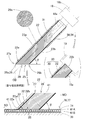
この塗布面25は、切断時に切断面が溶融しないように、すなわち、加熱しない状態のトムソン刃等によって切断された切断面から形成されており、外周縁26には、スキン層27からなる固化部27aが形成され、固化部27aに囲まれた内側では、繊維層28の各繊維28aの端末28bが露出された状態となっている。
なお、交差角度θは、塗布時に塗布面25の略全面を縫製部76に当てることから、縫製部76の補強対象面77と塗布材22の軸方向CDとの角度に一致することとなる。
また、移動台39の移動方向SDは、既述したように、補強対象面77に沿った鋭角の交差角度θの反対側の鈍角側の方向となっており、そのため、塗布面25における縫製部76に対する相対的な移動方向MDは、交差角度θ側の方向となる。
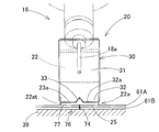
塗布材22を覆うカバー30は、図1~5に示すように、塗布材22より剛性のあるアルミニウム板や鋼板等の金属製として、塗布材22の外周面23を覆う略四角筒形状としている。すなわち、カバー30は、塗布材22の上面23aを覆う天井壁部31、下面23bを覆う底壁部34、及び、塗布材22の両側面23c,23cを覆う側壁部35,35、を備えて構成されている。カバー30は、塗布材22の塗布面25を設けた先端部22aから離れた元部22b側の外周面23の全域を覆うように構成されるとともに、塗布材22の外周面23に密着して塗布材22の型崩れを防止可能に、元部22b側を嵌挿させるような寸法に設定されている。
さらに、天井壁部31は、塗布材22の先端縁26aに接近するように延びて、凹部33を除き、先端縁26aと平行な端縁32aを有した先端支持部32、を備えている。この先端支持部32は、塗布材22における塗布面25の直上の断面三角柱状の三角部位22atの上面23aに接触して、塗布作業時の三角部位22atの上方への変形を規制するように支持する部位となる。
また、先端支持部32は、先端側の端縁32aにおける幅方向CWの中央に、断面三角柱状部位(三角部位)22atの上面23aの一部を露出させる凹部33、を備えている。凹部33は、端縁32aにかけて、テーパ状の三角形状に拡開するように、形成されている。
供給支持部18は、先端に、接着剤41を塗布材22側に供給可能な円管状の細い注射針状としたニードル部18aを備えて、元部側に、貯留部17の連結口部17bに結合されるニップル部18bを備えて構成されている。供給支持部18は、カバー30に覆われた塗布材22の元部側端面24に、ニードル部18aを差し込んで、塗布材22へ接着剤41を供給可能に塗布材22を支持する。換言すれば、塗布具20(塗布材22)は、単に、ニードル部18aから引き抜くだけで、容易に供給支持部18から取り外すことができ、その後、別の塗布具20を供給支持部18に取り付ける場合には、新たな塗布材22の元部側端面24に、ニードル部18aを差し込めば、容易に、新たな塗布具20を供給支持部18に取り付けることができて、塗布具20の交換作業を容易に行えるように構成されている。
貯留部17は、接着剤41を貯留したハウジング17aの先端に、供給支持部18のニップル部18bを組み付ける連結口部17bを備え、ハウジング17aの端面に、ディスペンサ11から供給される接着剤41を流入可能に、供給路12を接続させる流入口部17cを配設させて構成されている。
ディスペンサ11は、公知のものであり、接着剤41を所定の吐出圧で所定量供給できるように、構成されている。
この塗布装置10を使用した塗布工程を説明すれば、図1~5に示すように、移動台39の上方に配置させた塗布材22の塗布面25の下方に、基布61A,61Bの縫製部76を配置させるとともに、移動台39の移動方向SDに対応させて、縫製部76の縫製ラインSLを合わせて、移動台39上に基布61A,61Bをセットする。なお、この時、縫製部76の縫製ラインSLの上方で、塗布材22の軸方向CDが、縫製ラインSLと重なり、また、塗布材22の幅方向CWが縫製ラインSLと直交して配置されることとなる(図2参照)。換言すれば、この時、縫製部76の上方で、塗布材22が、その幅方向CWを縫製部76に接着剤41を塗布する補強対象面77の幅方向FWと一致させて配置されるとともに、塗布面25を補強対象面77と平行に配置させることとなる。
ついで、塗布動作手段37としてのホルダ38を下降させて塗布材22の塗布面25の全面を、一定荷重で縫製部76に当てるとともに、ディスペンサ11から貯留部17へ所定量の接着剤41を供給しつつ、移動方向SDに向けて、塗布動作手段37としての移動台39を一定速度で移動させれば、縫製部76の補強対象面77に接着剤41が塗布されて、塗布作業が行われる。そして、塗布する縫製部76の補強対象面77が無くなれば、ディスペンサ11から貯留部17への接着剤41の供給を停止させて、ホルダ38を上昇させて塗布材22の塗布面25を基布61A,61Bから離すとともに、移動台39の移動を停止させ、つぎの接着剤41の塗布作業の準備を行なう。
なお、接着剤41の塗布後には、加熱手段により接着剤41の硬化を促進させる。この加熱手段は、通常の熱風加熱、マイクロ波加熱等であってもよいが、局部加熱可能な赤外線(IR)等の加熱手段が望ましい。省エネルギーになるとともに、硬化工程を、縫製部76を形成する縫製工程や接着剤41を塗布する塗布工程と同期させて行うことが容易となるからである。
以上のように、実施形態の塗布装置10を使用した塗布方法では、補強対象面77の幅方向FWを一致させるように、幅方向CWを対応させて、塗布材22の先端における塗布面25の略全面を、一定荷重で補強対象面77に当てるとともに、塗布材22の軸方向CDを補強対象面77に対して鋭角の角度θとさせる側を、塗布面25の縫製部76に対する移動方向MD側として、縫製部76の縫製ラインSLに沿って、塗布材若しくはエアバッグ用基布の少なくとも一方(実施形態の場合は基布61側)を一定速度で移動させれば、塗布材22に含浸されていた接着剤41が、所定の幅寸法W0(W1)で、補強対象面77に塗布されることとなる。
その際、塗布材22の塗布面25は、図3,6,7に示すように、外周縁26をスキン層27の固化部27aで囲まれて、その固化部27aの内側に、繊維層28における塗布材22の軸方向CDに沿って揃えられたように配設されている熱融着性繊維28aの端末(端面)28bの束が、配置された状態となっている。そのため、刷毛状に配置された熱融着性繊維28aの端末28bが、縫製部76に対する移動方向MD側への移動により、若干曲がりつつ、その外周面や端面を利用して、固化部27aに位置規制された状態で、繊維28a間に含浸されていた接着剤41を、微小な刷毛で刷け塗りするように、補強対象面77に塗布する状態となる(図3の塗布概念説明図参照)。
そしてさらに、塗布面25は、塗布材22の軸方向CDを補強対象面77に対して鋭角の角度θとさせる側を、縫製部76に対する移動方向MD側として、移動させており、塗布面25における熱融着性繊維28aの端末28bやその周囲の固化部27aは、捲れるように大きく変形せずに、移動方向MDの前進側と逆方向SDの後退側に、若干、曲がるだけで、極力、塗布材22の幅方向CWに張り出すことが抑制される。そのため、接着剤41は、塗布面25の幅寸法W1で補強対象面77に対して塗布されることとなって、均一の厚さで、精度よく、両縁のエッジ(見切り)を明確にして、所定の幅寸法W1で塗布される。
また、塗布材22は、塗布面25を除いた外周面側がスキン層27に覆われており、塗布材22に含浸した接着剤41は、蒸発し難く、すなわち、硬化し難い状態で塗布材22内に含浸された状態を維持することから、塗布材22の部位での接着剤41の詰まりが抑制されて、所定のエアバッグ用基布61A,61Bの補強対象面77に対して接着剤41を塗布した後、つぎのエアバッグ用基布61A,61Bの補強対象面77に移行するまで、交換等せずに、塗布材22を空中に待機させておくことができ、塗布作業を簡便かつ効率的に行うことができる。
したがって、実施形態の縫製部76への接着剤41の塗布方法とその方法を実施する塗布装置10では、エアバッグ用基布61の縫製部76に補強用の接着剤41を塗布する際、簡便に、塗布幅W0を正確かつ明瞭に規定して塗布できるとともに、作業効率よく接着剤41を塗布できる。
なお、実施形態では、縫製部76に塗布された接着剤41は、塗布材22の幅寸法W1に対応する20mmの境界部を明確にした状態の塗布幅W0で、補強対象面77に塗布され、そして、図6に示すように、少なくとも、基布61A側の経糸71と緯糸72とに、毛細管現象を伴なって、深く浸透し、その後の硬化により、縫目の糸71,72のずれを的確に防止できて、好適に、縫製部76を補強することができた。
そして、実施形態の塗布装置10を使用した塗布方法では、塗布面25が、塗布材22の軸方向に対する交差角度θを、45~60°の範囲内の45°として設定されている。
そのため、実施形態では、所定寸法の塗布面25を容易に得ることができるとともに、耐久性を持って、接着剤41を塗布することができる。
なぜなら、塗布材22の塗布面25における塗布材22の軸方向CDに対する交差角度θが、45°未満であれば、塗布材22を押出成形品52から形成する工程での塗布面25を切断加工して形成する際、スキン層27を奇麗に切断し難く、特に、塗布材22の幅方向CWと直交する縁、すなわち、塗布時の塗布材22の移動方向MDに沿って対向する両縁26a,26b側で、長く残り易くなって、塗布面25を作成し難くなり、好ましくない。
また、塗布材22の塗布面25における塗布材22の軸方向CDに対する交差角度θが、60°を超えれば、60°以下の場合と比べて、塗布材22自体のエアバッグ用基布61への押圧力が同じとしても、塗布面25に露出している各熱融着性繊維28aに対し、それらの繊維28aに沿う方向の力、換言すれば、各繊維28aを縮める方向の力、が作用し易くなって、各繊維28aが座屈する現象を招き、含浸させた接着剤41を補強対象面77側に流す流路が塞がり易くなって、硬化を招く等して、塗布時の耐久性を低下させてしまい、好ましくない。ちなみに、塗布材22の塗布面25における塗布材22の軸方向CDに対する交差角度θが、60°以下であれば、塗布面25に露出させた各熱融着性繊維の端末28bが、塗布時の塗布材22の移動方向MDと逆方向SD側に、相互の隙間を略同等として、曲がることが可能となり、含浸させた接着剤41を補強対象面77側に流す流路を塞ぐことを抑制できて、耐久性を持って、塗布することができる。
そのため、塗布材22の塗布面25は、塗布材22の軸方向CDに対する交差角度θを、45~60°の範囲内として設定されていることが望ましく、実施形態の45°より、角度を広げてもよい。
そしてさらに、実施形態では、塗布材22が、塗布面25から離れた元部22b側で、接着剤41を定量供給可能なディスペンサ11から供給される接着剤41を貯留させた貯留部17と、接続されている。
そのため、実施形態では、塗布材22の塗布面25から補強対象面77に塗布された接着剤41の塗布量に応じて、塗布材22に対し、貯留部17を介して、ディスペンサ11からの接着剤41を供給できることから、補強対象面77に対して、一定量の接着剤41を塗布でき、所定幅W0に塗布できることと相俟って、安定した接着剤41の塗布量により、接着性能を向上させることに寄与できる。
なお、実施形態の場合、ディスペンサ11からの接着剤41の供給量を種々変化させても、塗布材22の塗布面25が補強対象面77に塗布した塗布量を計測したところ、同等となり、ディスペンサ11からの接着剤41の供給量に対応させて、塗布材22が、正確に、接着剤41を補強対象面77に塗布することができることを立証できた。
また、実施形態の塗布装置10では、塗布材22の外周側に、塗布材22より剛性を有して塗布材22を覆うカバー30が配設され、カバー30が、塗布材22における塗布面25の直上の断面三角柱状部位(三角部位)22atの上面23aを支持可能な先端支持部32、を備えて構成されている。
そのため、実施形態の塗布装置10では、塗布材22の塗布面25を設けた先端部22aが、塗布材22より剛性を有したカバー30の先端支持部32により支持されることから、先端部22aが、塗布材22の移動方向MDと逆方向SD側で、補強対象面77から離れて浮き上がるように曲がることが抑制される。そのため、塗布面25は、その全面を安定して補強対象面77に当てることができ、安定して、所定量の接着剤41を補強対象面77に塗布することができる。
さらに、実施形態の場合、カバー30は、塗布材22の外周面23の全面に密着して覆うような筒形状として、構成されており、先端部22a付近だけでなく、塗布材22の全体をカバー30により保護できて、塗布材22の型崩れを好適に防止でき、塗布材22の耐久性向上に寄与できる。
そしてまた、実施形態の場合、カバー30の先端支持部32が、先端(端縁)32a側における幅方向CWの中央に、断面三角柱状部位22atの上面23aの一部を露出させる凹部33、を備えて構成されている。
そのため、実施形態では、カバー30の先端支持部32の凹部33を、補強対象面77の縫製部76に一致させて、塗布作業を行えば、塗布材22の塗布面25の耐久性を、一層、向上させることができる。すなわち、塗布材22の塗布面25は、補強対象面77に当てられて、接着剤41を補強対象面77に塗布するが、その補強対象面77の縫製部76には、エアバッグ用基布61A,61Bを縫製した縫糸74が出っ張っており(図5参照)、その縫糸74の出っ張り分、縫製部76に対応する位置の塗布面25の部位が、先端支持部32側に上昇することとなる。その際、その部位の上方に凹部33が配設されていることから、その凹部33で上昇する変位分を収納することができる。そのため、塗布材22が、軸方向CDに沿った同一断面形状の押出成形品52から形成されていても、縫糸74の突出分、円滑に変形することができて、塗布材22は、部分的に圧縮変形されることを抑制されて、安定した塗布面25の形状を維持でき、塗布面25の耐久性を向上させることができる。
なお、凹部33としては、塗布材22の先端部22aの三角部位22at付近において、塗布面25の縫製部76と接触する部位の上方に配置されれば、実施形態のように、三角形状に限定されず、半円形状とした凹部でもよい。また、縫製部76と接触する部位の上方であれば、塗布面25の直上の全域に、前後方向に長く延びるスリット状の凹部を形成してもよい。
また、実施形態の塗布装置10では、塗布材22が、供給支持部18に対して、取り外し可能に支持されていることから、塗布材22を容易に交換することができて、塗布作業の効率向上に寄与できる。そのため、例えば、塗布作業時、接着剤41の詰まりや塗布面25の変形等により接着剤41のかすれ等が発生した際、あるいは、そのような現象の発生するようなタイミングの前に、塗布具20ごと、塗布材22を容易に交換することができて、好適となる。
なお、実施形態の場合、供給支持部18が、一本のニードル部18aを塗布材22に差し込んで、塗布材22を支持する構成としたが、接着剤41の供給可能な細い注射針状のニードル部を、塗布材22の幅方向CWに沿って複数並設し、それらの複数のニードル部を塗布材22に差し込んで、交換容易に塗布材22を支持する構成としてもよい。但し、このように、複数本の細いニードル部で塗布材22を支持する場合には、各二―ドル部内で接着剤41が詰まる虞れが生じ、安定して、支持できれば、実施形態のように、一本のニードル部18aを差し込んで塗布材22を支持する構成が好ましい。
また、供給支持部により、塗布材22を貯留部17側に組み付ける構造としては、塗布材の交換が容易であれば、図3の括弧書きに示すように、塗布材22の元部22b側を嵌め込むような嵌合部19aを設けた供給支持部19としてもよい。このような供給支持部19では、塗布材22自体の元部22bを嵌める構成のほか、交換自在であれば、カバー30と対応してクリップ止めできる係合部を形成して、塗布具20ごと支持できるように構成してもよい。また、このような供給支持部18,19は、貯留部17と別体で構成しても良いし、貯留部17と一体的に構成してもよい。
また、図例の基布61A,61Bの縫製部76では、縫糸74による一条縫製を例示したが、二条やそれ以上の複数状の縫製による縫製部に対し、接着剤41を塗布する際にも、本発明の塗布方法と塗布装置とを利用してもよい。
さらに、実施形態では、接着剤41の塗布時、塗布動作手段37としての移動台39を動作させて、エアバッグ用基布61A,61B側だけを一定速度で移動させたが、塗布動作手段37としての、一定荷重で塗布面25を補強対象面77に押下可能なホルダ38、を動作させて、塗布材22側だけを移動させたり、塗布動作手段37としてのユニット本体16を保持する保持手段としてのホルダ38と、塗布動作手段37としての基布61側をセットする基布セット側手段としての移動台39と、を共に動作させて、塗布材22側とエアバッグ用基布61A,61B側との両方を移動させてもよい。
なお、塗布材22側を移動させる場合には、図10に示すように、貯留部17、供給支持部18、及び、塗布具20を有したユニット本体16を、ホルダ38の代わりに、作業者が持つように、ハンディタイプとして、塗布装置10Aを構成してもよい。この塗布装置10Aでは、図示していないが、貯留部17に対し、供給路12を経て、接着剤41を定量供給可能なディスペンサ11からの接着剤41が供給されるように構成されている。
また、実施形態では、塗布材22の寸法形状として、幅寸法W1を20mm、厚さ寸法Tを6mmとしたものを例示した。この幅寸法W1は、既述したように、塗布片側幅寸法Wfとして5mm~15mmの範囲内が望ましいことから、その2倍程度の10~30mmの範囲内が望ましい。
塗布材22の厚さ寸法Tとしては、薄すぎては、強度不足となり、厚すぎては、材料の無駄となるとともに、塗布ムラが発生する虞れも生ずるこことから、幅寸法W1より小さくして、4~15mmの範囲内が望ましい。
10,10A…塗布装置、11…ディスペンサ、17…(シリンダ)貯留部、18…(ニードル)供給支持部、19…(嵌合部)供給支持部、22…塗布材、22a…先端部、22at…三角部位、23…外周面、23a…(天井面)上面、25…(先端面)塗布面、26…外周縁、27…スキン層、27a…固化部、28a…熱融着性繊維、30…カバー、32…先端支持部、32a…先端・端縁、33…凹部、41…接着剤、50…押出成形機、52…押出成形品、61(61A,61B)…エアバッグ用基布、71…経糸、72…緯糸、74…縫糸、76…縫製部、77…補強対象面、
SL…縫製ライン、PD…(押出成形品の)押出方向、CD…(塗布材の)軸方向、FW…(補強対象面の)幅方向、CW…(塗布材の)幅方向、W0…(補強対象面の)幅寸法、W1…(塗布材の)幅寸法、MD…(塗布面の縫製部に対する)移動方向。
SL…縫製ライン、PD…(押出成形品の)押出方向、CD…(塗布材の)軸方向、FW…(補強対象面の)幅方向、CW…(塗布材の)幅方向、W0…(補強対象面の)幅寸法、W1…(塗布材の)幅寸法、MD…(塗布面の縫製部に対する)移動方向。
Claims (9)
- 経糸と緯糸とを織ってなるエアバッグ用基布を縫製した縫製部を配設させた補強対象面に対し、塗布材に含浸させた接着剤を塗布する下記工程の塗布工程、を備えた縫製部への接着剤の塗布方法であり、
前記塗布材は、押出成形品を、前記塗布材の軸方向と交差する交差角度として、切断するとともに、前記押出成形品の断面の全域で切断した平面状の切断面を形成しつつ、所定長さに切断して形成され、
前記押出成形品は、
熱融着性繊維を押出方向に揃えるとともに、押出方向を前記塗布材の軸方向に配置させ、かつ、前記補強対象面の幅寸法に対応する幅寸法とし、さらに、外周面にスキン層を残して、押出成形して、形成され、
前記塗布工程は、
前記塗布材に、前記接着剤を毛細管現象を利用して含浸させ、
前記塗布材の前記切断面を塗布面として、該塗布面の略全面を、幅方向を対応させて、前記補強対象面に当てるとともに、
前記塗布材の軸方向を前記補強対象面に対して鋭角とさせる側を、前記塗布面の前記縫製部に対する移動方向側として、
前記塗布材若しくは前記エアバッグ用基布の少なくとも一方を移動させて、
前記接着剤を前記補強対象面に塗布することを特徴とする縫製部への接着剤の塗布方法。 - 前記塗布面が、前記塗布材の軸方向に対する前記交差角度を、45~60°の範囲内として設定されていることを特徴とする請求項1に記載の縫製部への接着剤の塗布方法。
- 前記塗布材が、前記塗布面から離れた元部側で、前記接着剤を定量供給可能なディスペンサから供給される前記接着剤を貯留させた貯留部と、接続されていることを特徴とする請求項1若しくは請求項2に記載の縫製部への接着剤の塗布方法。
- 経糸と緯糸とを織ってなるエアバッグ用基布を縫製した縫製部を配設させた補強対象面に対し、塗布材に含浸させた補強用接着剤を塗布する塗布装置であり、
前記塗布材と、
前記接着剤を貯留した貯留部と、
前記塗布材へ前記接着剤を供給可能に、前記塗布材を支持して前記貯留部に対して組み付ける供給支持部と、
を備え、
前記塗布材は、
押出成形品を、前記塗布材の軸方向と交差する交差角度として、切断するとともに、前記押出成形品の断面の全域で切断した平面状の切断面を形成しつつ、所定長さに切断して形成され、
前記押出成形品は、
熱融着性繊維を押出方向に揃えるとともに、押出方向を前記塗布材の軸方向に配置させ、かつ、前記補強対象面の幅寸法に対応する幅寸法とし、さらに、外周面にスキン層を残して、押出成形して、形成され、
前記塗布材は、
先端に塗布面を配置させて、該塗布面を前記補強対象面に当てて、前記塗布材若しくは前記エアバッグ用基布の少なくとも一方を移動させて、前記接着剤を前記補強対象面に塗布するように配設され、
前記塗布材の塗布面は、外周縁に前記スキン層の固化部を有し、かつ、前記補強対象面の幅寸法に対応する幅寸法を維持して、前記塗布材の軸方向と交差する交差角度を有した平面状の切断面、から構成されていることを特徴とする塗布装置。 - 前記塗布面が、前記塗布材の軸方向に対する前記交差角度を、45~60°の範囲内として設定されていることを特徴とする請求項4に記載の塗布装置。
- 前記塗布材の外周側に、前記塗布材より剛性を有して前記塗布材を覆うカバーが配設され、
前記カバーが、前記塗布材における前記塗布面の直上の断面三角柱状部位の上面を支持可能な先端支持部、を備えて構成されていることを特徴とする請求項4若しくは請求項5に記載の塗布装置。 - 前記カバーの前記先端支持部が、先端側における幅方向の中央に、断面三角柱状部位の上面の一部を露出させる凹部、を備えて構成されていることを特徴とする請求項6に記載の塗布装置。
- 前記塗布材が、前記供給支持部に対して、取り外し可能に支持されていることを特徴とする請求項4乃至請求項7のいずれか1項に記載の塗布装置。
- 前記貯留部が、前記接着剤を定量供給可能なディスペンサと接続されていることを特徴とする請求項4乃至請求項8のいずれか1項に記載の塗布装置。
Applications Claiming Priority (2)
| Application Number | Priority Date | Filing Date | Title |
|---|---|---|---|
| JP2016068882A JP2017177019A (ja) | 2016-03-30 | 2016-03-30 | 縫製部への接着剤の塗布方法と塗布装置 |
| JP2016-068882 | 2016-03-30 |
Publications (1)
| Publication Number | Publication Date |
|---|---|
| WO2017169388A1 true WO2017169388A1 (ja) | 2017-10-05 |
Family
ID=59964107
Family Applications (1)
| Application Number | Title | Priority Date | Filing Date |
|---|---|---|---|
| PCT/JP2017/007088 Ceased WO2017169388A1 (ja) | 2016-03-30 | 2017-02-24 | 縫製部への接着剤の塗布方法と塗布装置 |
Country Status (2)
| Country | Link |
|---|---|
| JP (1) | JP2017177019A (ja) |
| WO (1) | WO2017169388A1 (ja) |
Cited By (5)
| Publication number | Priority date | Publication date | Assignee | Title |
|---|---|---|---|---|
| CN112705419A (zh) * | 2020-12-23 | 2021-04-27 | 海宁市丰达电子有限公司 | 一种天线端头快速组装用的一体成型机 |
| US11214895B2 (en) | 2015-11-06 | 2022-01-04 | Inv Performance Materials, Llc | Low permeability and high strength fabric and methods of making the same |
| US11634841B2 (en) | 2017-05-02 | 2023-04-25 | Inv Performance Materials, Llc | Low permeability and high strength woven fabric and methods of making the same |
| US11708045B2 (en) | 2017-09-29 | 2023-07-25 | Inv Performance Materials, Llc | Airbags and methods for production of airbags |
| EP4074888A4 (en) * | 2019-12-27 | 2023-09-20 | Kolon Industries, Inc. | AIRBAG FABRIC HAVING IMPROVED DURABILITY AND METHOD FOR PRODUCING THE SAME |
Families Citing this family (3)
| Publication number | Priority date | Publication date | Assignee | Title |
|---|---|---|---|---|
| JP6806011B2 (ja) | 2017-09-14 | 2020-12-23 | 株式会社デンソー | 画像処理装置 |
| JP7390136B2 (ja) * | 2019-09-02 | 2023-12-01 | リンテック株式会社 | 接着剤塗布装置および接着剤塗布方法 |
| KR102652989B1 (ko) * | 2024-01-23 | 2024-03-29 | 김현석 | 요실금 팬티 발수처리방법 |
Citations (8)
| Publication number | Priority date | Publication date | Assignee | Title |
|---|---|---|---|---|
| JPS5233666U (ja) * | 1975-08-29 | 1977-03-09 | ||
| JPS6361931U (ja) * | 1986-10-13 | 1988-04-23 | ||
| JP2002302863A (ja) * | 2001-04-02 | 2002-10-18 | Kuraray Co Ltd | 塗装具用繊維構造体およびその製造方法 |
| JP2003291592A (ja) * | 2002-03-29 | 2003-10-15 | Pentel Corp | 塗布具 |
| JP2005138704A (ja) * | 2003-11-06 | 2005-06-02 | Nippon Plast Co Ltd | エアバッグ |
| JP2010105652A (ja) * | 2008-09-30 | 2010-05-13 | Toyoda Gosei Co Ltd | エアバッグ |
| JP2011182931A (ja) * | 2010-03-08 | 2011-09-22 | Kao Corp | アプリケータ装置 |
| JP2014528832A (ja) * | 2011-09-26 | 2014-10-30 | ディスペンシング・テクノロジーズ・ベスローテン・フェンノートシャップDispensing Technologies B.V. | ポータブルで自己充足的装置から一つ以上の液体を分配するシステム及び方法(工業的フレアー) |
-
2016
- 2016-03-30 JP JP2016068882A patent/JP2017177019A/ja active Pending
-
2017
- 2017-02-24 WO PCT/JP2017/007088 patent/WO2017169388A1/ja not_active Ceased
Patent Citations (8)
| Publication number | Priority date | Publication date | Assignee | Title |
|---|---|---|---|---|
| JPS5233666U (ja) * | 1975-08-29 | 1977-03-09 | ||
| JPS6361931U (ja) * | 1986-10-13 | 1988-04-23 | ||
| JP2002302863A (ja) * | 2001-04-02 | 2002-10-18 | Kuraray Co Ltd | 塗装具用繊維構造体およびその製造方法 |
| JP2003291592A (ja) * | 2002-03-29 | 2003-10-15 | Pentel Corp | 塗布具 |
| JP2005138704A (ja) * | 2003-11-06 | 2005-06-02 | Nippon Plast Co Ltd | エアバッグ |
| JP2010105652A (ja) * | 2008-09-30 | 2010-05-13 | Toyoda Gosei Co Ltd | エアバッグ |
| JP2011182931A (ja) * | 2010-03-08 | 2011-09-22 | Kao Corp | アプリケータ装置 |
| JP2014528832A (ja) * | 2011-09-26 | 2014-10-30 | ディスペンシング・テクノロジーズ・ベスローテン・フェンノートシャップDispensing Technologies B.V. | ポータブルで自己充足的装置から一つ以上の液体を分配するシステム及び方法(工業的フレアー) |
Cited By (7)
| Publication number | Priority date | Publication date | Assignee | Title |
|---|---|---|---|---|
| US11214895B2 (en) | 2015-11-06 | 2022-01-04 | Inv Performance Materials, Llc | Low permeability and high strength fabric and methods of making the same |
| US11634841B2 (en) | 2017-05-02 | 2023-04-25 | Inv Performance Materials, Llc | Low permeability and high strength woven fabric and methods of making the same |
| US11708045B2 (en) | 2017-09-29 | 2023-07-25 | Inv Performance Materials, Llc | Airbags and methods for production of airbags |
| EP4074888A4 (en) * | 2019-12-27 | 2023-09-20 | Kolon Industries, Inc. | AIRBAG FABRIC HAVING IMPROVED DURABILITY AND METHOD FOR PRODUCING THE SAME |
| US12060028B2 (en) | 2019-12-27 | 2024-08-13 | Kolon Industries, Inc. | Fabric for airbag and method for manufacturing the same |
| CN112705419A (zh) * | 2020-12-23 | 2021-04-27 | 海宁市丰达电子有限公司 | 一种天线端头快速组装用的一体成型机 |
| CN112705419B (zh) * | 2020-12-23 | 2021-11-09 | 海宁市丰达电子有限公司 | 一种天线端头快速组装用的一体成型机 |
Also Published As
| Publication number | Publication date |
|---|---|
| JP2017177019A (ja) | 2017-10-05 |
Similar Documents
| Publication | Publication Date | Title |
|---|---|---|
| WO2017169388A1 (ja) | 縫製部への接着剤の塗布方法と塗布装置 | |
| CN105463855B (zh) | 缝制气囊及其制造方法 | |
| US10695992B2 (en) | System and method for 3D printing on permeable materials | |
| US8334225B2 (en) | Stretchable artificial leather | |
| US10377104B2 (en) | Composite skin material for vehicle | |
| CN102529868A (zh) | 气囊 | |
| JP5280303B2 (ja) | ヌバック調シート状物およびその製造方法 | |
| JP2017513733A (ja) | 複合プリフォームの製造方法 | |
| CN104838063B (zh) | 片状物及该片状物的制造方法 | |
| EP2737121B1 (en) | Fabric finishing | |
| JP2011069031A (ja) | 合成皮革の製造方法 | |
| TWI877193B (zh) | 書寫用具 | |
| EP0331215A2 (en) | A process for laminating textiles | |
| KR102147131B1 (ko) | 화장품 용기의 장식재로 사용되는 인조피혁 및 그 가공 장식방법 | |
| JP2012031535A (ja) | エアバッグ用基布 | |
| CN116348309A (zh) | 书写工具用纤维束体、使用其的笔尖、书写工具 | |
| JP2017105350A (ja) | エアバッグ用基布の製造方法 | |
| JP2008221724A (ja) | 繊維束及びその接合方法、並びに、frp成形体の製造方法 | |
| JP6275397B2 (ja) | 多孔質積層体、吸着緩衝材、及び吸着方法 | |
| JP2010276058A (ja) | ロール及び洗浄装置 | |
| JP6809001B2 (ja) | 弁ユニット、印刷装置および印刷方法 | |
| US7431982B2 (en) | Cushion sheet and manufacturing method for a cushion sheet | |
| KR102420395B1 (ko) | 연신 폴리프로필렌을 이용한 기능성 나노 멤브레인 원단의 제조 방법 및 그 기능성 나노 멤브레인 원단 | |
| KR102393549B1 (ko) | 연신 폴리프로필렌을 이용한 항균 나노 멤브레인 원단의 제조 방법 및 그 항균 나노 멤브레인 원단 | |
| KR20220047993A (ko) | 필기구 |
Legal Events
| Date | Code | Title | Description |
|---|---|---|---|
| NENP | Non-entry into the national phase |
Ref country code: DE |
|
| 121 | Ep: the epo has been informed by wipo that ep was designated in this application |
Ref document number: 17773933 Country of ref document: EP Kind code of ref document: A1 |
|
| 122 | Ep: pct application non-entry in european phase |
Ref document number: 17773933 Country of ref document: EP Kind code of ref document: A1 |