WO2017168615A1 - Power transmission device - Google Patents
Power transmission device Download PDFInfo
- Publication number
- WO2017168615A1 WO2017168615A1 PCT/JP2016/060330 JP2016060330W WO2017168615A1 WO 2017168615 A1 WO2017168615 A1 WO 2017168615A1 JP 2016060330 W JP2016060330 W JP 2016060330W WO 2017168615 A1 WO2017168615 A1 WO 2017168615A1
- Authority
- WO
- WIPO (PCT)
- Prior art keywords
- gear
- clutch
- driven gear
- power transmission
- transmission device
- Prior art date
Links
Images


Classifications
-
- B—PERFORMING OPERATIONS; TRANSPORTING
- B62—LAND VEHICLES FOR TRAVELLING OTHERWISE THAN ON RAILS
- B62M—RIDER PROPULSION OF WHEELED VEHICLES OR SLEDGES; POWERED PROPULSION OF SLEDGES OR SINGLE-TRACK CYCLES; TRANSMISSIONS SPECIALLY ADAPTED FOR SUCH VEHICLES
- B62M11/00—Transmissions characterised by the use of interengaging toothed wheels or frictionally-engaging wheels
- B62M11/04—Transmissions characterised by the use of interengaging toothed wheels or frictionally-engaging wheels of changeable ratio
- B62M11/06—Transmissions characterised by the use of interengaging toothed wheels or frictionally-engaging wheels of changeable ratio with spur gear wheels
-
- F—MECHANICAL ENGINEERING; LIGHTING; HEATING; WEAPONS; BLASTING
- F16—ENGINEERING ELEMENTS AND UNITS; GENERAL MEASURES FOR PRODUCING AND MAINTAINING EFFECTIVE FUNCTIONING OF MACHINES OR INSTALLATIONS; THERMAL INSULATION IN GENERAL
- F16D—COUPLINGS FOR TRANSMITTING ROTATION; CLUTCHES; BRAKES
- F16D25/00—Fluid-actuated clutches
- F16D25/12—Details not specific to one of the before-mentioned types
-
- F—MECHANICAL ENGINEERING; LIGHTING; HEATING; WEAPONS; BLASTING
- F16—ENGINEERING ELEMENTS AND UNITS; GENERAL MEASURES FOR PRODUCING AND MAINTAINING EFFECTIVE FUNCTIONING OF MACHINES OR INSTALLATIONS; THERMAL INSULATION IN GENERAL
- F16H—GEARING
- F16H3/00—Toothed gearings for conveying rotary motion with variable gear ratio or for reversing rotary motion
- F16H3/02—Toothed gearings for conveying rotary motion with variable gear ratio or for reversing rotary motion without gears having orbital motion
- F16H3/20—Toothed gearings for conveying rotary motion with variable gear ratio or for reversing rotary motion without gears having orbital motion exclusively or essentially using gears that can be moved out of gear
- F16H3/22—Toothed gearings for conveying rotary motion with variable gear ratio or for reversing rotary motion without gears having orbital motion exclusively or essentially using gears that can be moved out of gear with gears shiftable only axially
- F16H3/30—Toothed gearings for conveying rotary motion with variable gear ratio or for reversing rotary motion without gears having orbital motion exclusively or essentially using gears that can be moved out of gear with gears shiftable only axially with driving and driven shafts not coaxial
-
- B—PERFORMING OPERATIONS; TRANSPORTING
- B60—VEHICLES IN GENERAL
- B60Y—INDEXING SCHEME RELATING TO ASPECTS CROSS-CUTTING VEHICLE TECHNOLOGY
- B60Y2200/00—Type of vehicle
- B60Y2200/10—Road Vehicles
- B60Y2200/12—Motorcycles, Trikes; Quads; Scooters
-
- F—MECHANICAL ENGINEERING; LIGHTING; HEATING; WEAPONS; BLASTING
- F16—ENGINEERING ELEMENTS AND UNITS; GENERAL MEASURES FOR PRODUCING AND MAINTAINING EFFECTIVE FUNCTIONING OF MACHINES OR INSTALLATIONS; THERMAL INSULATION IN GENERAL
- F16H—GEARING
- F16H57/00—General details of gearing
- F16H57/02—Gearboxes; Mounting gearing therein
- F16H2057/0203—Gearboxes; Mounting gearing therein the gearbox is associated or combined with a crank case of an engine
-
- F—MECHANICAL ENGINEERING; LIGHTING; HEATING; WEAPONS; BLASTING
- F16—ENGINEERING ELEMENTS AND UNITS; GENERAL MEASURES FOR PRODUCING AND MAINTAINING EFFECTIVE FUNCTIONING OF MACHINES OR INSTALLATIONS; THERMAL INSULATION IN GENERAL
- F16H—GEARING
- F16H61/00—Control functions within control units of change-speed- or reversing-gearings for conveying rotary motion ; Control of exclusively fluid gearing, friction gearing, gearings with endless flexible members or other particular types of gearing
- F16H61/04—Smoothing ratio shift
- F16H2061/047—Smoothing ratio shift by preventing or solving a tooth butt situation upon engagement failure due to misalignment of teeth
-
- F—MECHANICAL ENGINEERING; LIGHTING; HEATING; WEAPONS; BLASTING
- F16—ENGINEERING ELEMENTS AND UNITS; GENERAL MEASURES FOR PRODUCING AND MAINTAINING EFFECTIVE FUNCTIONING OF MACHINES OR INSTALLATIONS; THERMAL INSULATION IN GENERAL
- F16H—GEARING
- F16H2200/00—Transmissions for multiple ratios
- F16H2200/003—Transmissions for multiple ratios characterised by the number of forward speeds
- F16H2200/0043—Transmissions for multiple ratios characterised by the number of forward speeds the gear ratios comprising four forward speeds
-
- F—MECHANICAL ENGINEERING; LIGHTING; HEATING; WEAPONS; BLASTING
- F16—ENGINEERING ELEMENTS AND UNITS; GENERAL MEASURES FOR PRODUCING AND MAINTAINING EFFECTIVE FUNCTIONING OF MACHINES OR INSTALLATIONS; THERMAL INSULATION IN GENERAL
- F16H—GEARING
- F16H63/00—Control outputs from the control unit to change-speed- or reversing-gearings for conveying rotary motion or to other devices than the final output mechanism
- F16H63/02—Final output mechanisms therefor; Actuating means for the final output mechanisms
- F16H63/08—Multiple final output mechanisms being moved by a single common final actuating mechanism
- F16H63/16—Multiple final output mechanisms being moved by a single common final actuating mechanism the final output mechanisms being successively actuated by progressive movement of the final actuating mechanism
- F16H63/18—Multiple final output mechanisms being moved by a single common final actuating mechanism the final output mechanisms being successively actuated by progressive movement of the final actuating mechanism the final actuating mechanism comprising cams
Definitions
- the present invention includes a clutch outer that is supported on an input shaft so as to be relatively rotatable and holds a friction plate, and a clutch hub that is supported on an input shaft so as not to be relatively rotatable and holds a clutch plate that can be frictionally joined to the friction plate.
- the present invention relates to a power transmission device including a shifter that is supported and has a second engagement protrusion that engages with the first engagement protrusion when moved from an axial reference position to an operation position.
- the friction damper is held inside the frame body, an annular frame body fitted into the clutch gear from the shaft end side protruding from the crankcase. A transmission member.
- part of the power is transmitted from the clutch outer to the clutch hub by the action of the friction damper even when the friction plate and the clutch plate are disengaged.
- the active gear rotates by receiving power from the clutch hub. A relative rotation is thus caused between the active gear and the driven gear.
- the active gear moves from the axial reference position to the operating position, even if the first engagement protrusion hits the second engagement protrusion and the axial movement of the active gear is prevented, the first engagement protrusion is caused by relative rotation. It is possible to enter the adjacent space of the second engagement protrusion. Thus, a coupling state can be smoothly established between the first engagement protrusion and the second engagement protrusion.
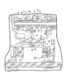
- a dog clutch type multi-stage transmission 39 is incorporated in the engine 25.
- the multi-stage transmission 39 includes an input shaft 41 and an output shaft 42 having an axis parallel to the axis of the crankshaft 31.
- the input shaft 41 and the output shaft 42 are rotatably supported by the first case half 26a and the second case half 26b by bearings 43 and 44 that are fitted into the first case half 26a and the second case half 26b, respectively.
- the input shaft 41 is connected to the crankshaft 31 through the primary reduction mechanism 45.
- the primary reduction mechanism 45 includes a drive gear 45a fixed to the crankshaft 31 and a driven gear 45b supported on the output shaft 42 so as to be relatively rotatable.
- the driven gear 45b meshes with the drive via 45a.
- a drive sprocket 32 is coupled to the output shaft 42.
- the rotor 59 and the stator 61 are accommodated in a space defined by the generator cover 62 and the first case half 26a.
- the ACG starter 58 functions as a starter motor that automatically starts the crankshaft 31 when the engine 25 is started. When the start of the engine 25 is confirmed, the ACG starter 58 functions as an AC generator.
- a first fitting mechanism 74 is configured between the 4-speed drive gear 47 and the 3-speed drive gear 48.
- the first fitting mechanism 74 includes a plurality of drive protrusions 75 formed on the first shifter 72 and a plurality of driven protrusions 76 formed on the fourth speed drive gear 47.
- the drive protrusion 75 When the first shifter 72 is displaced from the axial reference position toward the fourth speed drive gear 47 by the first distance and moved to the first operation position, the drive protrusion 75 is moved in the circumferential direction on the fourth speed drive gear 47. It enters between the drive protrusions 76.
- the driving protrusion 75 is in surface contact with the driven protrusion 76 in the rotation direction of the input shaft 41.
- Each of the driving protrusion 75 and the driven protrusion 76 has a contact surface that extends in a virtual plane including the axis of the input shaft 41. In this way, the driven protrusion 76 and the driving protrusion 75 mesh with each other around the axis of the input shaft 41.
- the 4-speed drive gear 47 is coupled to the input shaft 41 through the first shifter 72 so as not to be relatively rotatable.
- a second fitting mechanism 77 is configured between the third speed driving gear 48 and the second speed driving gear 49.
- the second fitting mechanism 77 includes a plurality of driving protrusions 78 formed on the first shifter 72 and a plurality of driven protrusions 79 formed on the second speed driving gear 49.
- a third fitting mechanism 83 is configured between the low driven gear 51 and the fourth speed driven gear 52.
- the third fitting mechanism 83 includes a plurality of driving protrusions 84 formed on the second shifter 81 and a plurality of driven protrusions 85 formed on the low driven gear 51.
- the drive protrusion 78 of the first shifter 72 is moved to the second speed by the second fitting mechanism 77. It meshes with the driven projection 79 of the drive gear 49.
- the second speed drive gear 49 is coupled to the input shaft 41.
- the third speed drive gear 48 is disengaged from the third speed driven gear 53 of the output shaft 42 as the first shifter 72 moves.
- the meshing of the third speed driving gear 48 and the third speed driven gear 53 is eliminated.
- the rotational force of the input shaft 41 is transmitted to the second speed drive gear 49. Since the second speed drive gear 49 of the input shaft 41 meshes with the second speed driven gear 54 of the output shaft 42, the rotational force of the input shaft 41 drives the output shaft 42.
- the second speed is established in the multi-stage transmission 39.
- the driving protrusion 87 of the second shifter 81 is 3 by the fourth fitting mechanism 86.
- the third speed driven gear 53 is coupled to the output shaft 42.
- the 4-speed driven gear 52 is disengaged from the 4-speed drive gear 47 of the input shaft 41 as the second shifter 81 moves.
- the meshing between the 4-speed drive gear 47 and the 4-speed driven gear 52 is eliminated.
- the rotational force of the input shaft 41 transmitted to the third speed driven gear 53 drives the output shaft 42. In this manner, the third speed is established in the multi-stage transmission 39.
- the shift mechanism 89 includes a shift drum 93.
- the shift drum 93 is supported so as to be rotatable about an axis extending parallel to the axis of the guide shaft 91.
- a cam groove 94 is formed on the outer peripheral surface of the shift drum 93.
- the cam groove 94 is displaced in the axial direction of the shift drum 93 according to the rotation angle.
- a pin 95 protruding from the shift fork 92 in a direction perpendicular to the axis of the guide shaft 91 is inserted into the cam groove 94.
- the shift fork 92 moves along the guide shaft 91 according to the rotation of the shift drum 93.
- the movement of the shift fork 92 causes the movement of the first shifter 72 on the input shaft 41.
- a similar shift mechanism is also associated with the second shifter 81 on the output shaft 42.
- the transmission member 114 includes an annular fixing frame 114 a that is bonded to the inner surface of the frame body 113, and a contact piece 114 b that is biased inward as the distance from the fixing frame 114 a is parallel to the outer periphery of the frame body 113.
- the fixing frame 114a and the contact piece 114b may be integrally formed from rubber.
- the contact piece 114b comes into surface contact with the guide cylinder 102 with a predetermined contact pressure.
- the rotation of the clutch gear 96 is transmitted to the clutch hub 57 around the axis of the input shaft 41 based on the contact pressure of the contact piece 114b.
Abstract
Description
26…クランクケース
31…クランクシャフト
39…多段変速機
41…入力軸
42…出力軸
51…従動ギア(ロー被駆動ギア)
52…能動ギア(4速被駆動ギア)
56…クラッチアウター
57…クラッチハブ
58…ACGスターター
64…キックスターター
68…キックスターター用駆動ギア
69…キックスターター用被駆動ギア
84…第1係合突起(駆動突起)
85…第2係合突起(被駆動突起)
96…クラッチギア
97…保持部材
98…フリクション板
101…ダンパー
105…クラッチ板
112…フリクションダンパー
113…枠体
114…伝達部材
114a…固着枠
114b…接触片 25 ...
52 ... Active gear (4-speed driven gear)
56 ... Clutch outer 57 ... Clutch
85: Second engaging protrusion (driven protrusion)
96 ...
Claims (5)
- 動力入力側に連結されて、フリクション板(98)を保持するクラッチアウター(56)と、
前記クラッチアウター(56)に対して相対回転自在に支持されて、前記フリクション板(98)に摩擦接合可能なクラッチ板(105)を保持するクラッチハブ(57)と、
前記クラッチハブ(57)に連結されて、第1係合突起(84)を有する能動ギア(52)と、
軸方向に変位可能に前記能動ギア(52)に同軸に支持されて、軸方向基準位置から軸方向に作動位置に移動すると前記第1係合突起(84)に係り合う第2係合突起(85)を有する従動ギア(51)と、
前記クラッチアウター(56)および前記クラッチハブ(57)の間に介在するフリクションダンパー(112)と
を備えることを特徴とする動力伝達装置。 A clutch outer (56) connected to the power input side and holding the friction plate (98);
A clutch hub (57) that holds a clutch plate (105) that is rotatably supported relative to the clutch outer (56) and that can be frictionally joined to the friction plate (98);
An active gear (52) coupled to the clutch hub (57) and having a first engagement protrusion (84);
A second engaging protrusion (44) that is supported coaxially by the active gear (52) so as to be displaceable in the axial direction and engages with the first engaging protrusion (84) when moved from the axial reference position to the operating position in the axial direction. 85) a driven gear (51) having
A power transmission device comprising a friction damper (112) interposed between the clutch outer (56) and the clutch hub (57). - 請求項1に記載の動力伝達装置において、前記クラッチアウター(56)は、
前記クラッチハブ(57)に対して前記フリクションダンパー(112)を押し当てながら前記フリクションダンパー(112)を保持するクラッチギア(96)と、
前記クラッチハブ(57)の回転軸回りで相対回転自在に前記クラッチギア(96)に支持されて、前記フリクション板(98)を保持する保持部材(97)と、
周方向に前記クラッチギア(96)および前記保持部材(97)の間に配置され両者を周方向に連結するダンパー(101)と
を備えることを特徴とする動力伝達装置。 The power transmission device according to claim 1, wherein the clutch outer (56) is
A clutch gear (96) for holding the friction damper (112) while pressing the friction damper (112) against the clutch hub (57);
A holding member (97) that is supported by the clutch gear (96) so as to be relatively rotatable about a rotation axis of the clutch hub (57) and holds the friction plate (98);
A power transmission device comprising: a damper (101) disposed between the clutch gear (96) and the holding member (97) in the circumferential direction and connecting both in the circumferential direction. - 請求項2に記載の動力伝達装置において、前記フリクションダンパー(112)は、クランクケース(26)から突き出す軸端側から前記クラッチギア(96)に嵌め入れられる環状の枠体(113)と、前記枠体(113)の内側に保持される伝達部材(114)とを備えることを特徴とする動力伝達装置。 The power transmission device according to claim 2, wherein the friction damper (112) includes an annular frame (113) fitted into the clutch gear (96) from a shaft end side protruding from a crankcase (26), and A power transmission device comprising: a transmission member (114) held inside the frame (113).
- 請求項3に記載の動力伝達装置において、前記クラッチギア(96)の前記クランクケース(26)側で前記クラッチギア(96)に一体に形成され、キックスターター(64)のスターター駆動ギア(68)に噛み合うキックスターター用のスターター被駆動ギア(69)を備えることを特徴とする動力伝達装置。 The power transmission apparatus according to claim 3, wherein the starter drive gear (68) of the kick starter (64) is integrally formed with the clutch gear (96) on the crankcase (26) side of the clutch gear (96). A power transmission device comprising a starter driven gear (69) for a kick starter that meshes with the starter.
- 請求項1~4のいずれか1項に記載の動力伝達装置において、
前記能動ギア(52)および前記従動ギア(51)を含む駆動ギアまたは被駆動ギアを支持する第1軸(42)、並びに、前記駆動ギアまたは前記被駆動ギアに噛み合い可能な被駆動ギアまたは駆動ギアを支持する第2軸(41)を含む多段変速機(39)で、前記第1軸(42)および前記第2軸(41)の間で動力の伝達を切断するニュートラル状態が確立され、前記フリクション板(98)および前記クラッチ板(105)の間で摩擦接合が確立されると、エンジン(25)の燃焼動作を停止する制御回路と、
前記エンジン(25)のクランクシャフト(31)に接続されて、前記ニュートラル状態で前記摩擦接合が再び解除されると前記制御回路からの指令信号を受けてクランクシャフト(31)を自動始動するスターターモーター(58)と
を備えることを特徴とする動力伝達装置。
The power transmission device according to any one of claims 1 to 4,
A first shaft (42) that supports a drive gear or a driven gear including the active gear (52) and the driven gear (51), and a driven gear or a drive that can mesh with the drive gear or the driven gear. In the multi-stage transmission (39) including the second shaft (41) supporting the gear, a neutral state is established that cuts off the transmission of power between the first shaft (42) and the second shaft (41). A control circuit that stops the combustion operation of the engine (25) when frictional connection is established between the friction plate (98) and the clutch plate (105);
A starter motor connected to the crankshaft (31) of the engine (25) and automatically starting the crankshaft (31) in response to a command signal from the control circuit when the frictional connection is released again in the neutral state. (58). The power transmission device characterized by the above-mentioned.
Priority Applications (4)
| Application Number | Priority Date | Filing Date | Title |
|---|---|---|---|
| JP2018507922A JP6640329B2 (en) | 2016-03-30 | 2016-03-30 | Power transmission device |
| EP16896835.2A EP3438489B1 (en) | 2016-03-30 | 2016-03-30 | Power transmission device |
| CN201680086146.XA CN109154335B (en) | 2016-03-30 | 2016-03-30 | Power transmission device |
| PCT/JP2016/060330 WO2017168615A1 (en) | 2016-03-30 | 2016-03-30 | Power transmission device |
Applications Claiming Priority (1)
| Application Number | Priority Date | Filing Date | Title |
|---|---|---|---|
| PCT/JP2016/060330 WO2017168615A1 (en) | 2016-03-30 | 2016-03-30 | Power transmission device |
Publications (1)
| Publication Number | Publication Date |
|---|---|
| WO2017168615A1 true WO2017168615A1 (en) | 2017-10-05 |
Family
ID=59963686
Family Applications (1)
| Application Number | Title | Priority Date | Filing Date |
|---|---|---|---|
| PCT/JP2016/060330 WO2017168615A1 (en) | 2016-03-30 | 2016-03-30 | Power transmission device |
Country Status (4)
| Country | Link |
|---|---|
| EP (1) | EP3438489B1 (en) |
| JP (1) | JP6640329B2 (en) |
| CN (1) | CN109154335B (en) |
| WO (1) | WO2017168615A1 (en) |
Cited By (1)
| Publication number | Priority date | Publication date | Assignee | Title |
|---|---|---|---|---|
| EP3514400A1 (en) * | 2018-01-10 | 2019-07-24 | Honda Motor Co., Ltd. | Multiplate friction clutch |
Families Citing this family (2)
| Publication number | Priority date | Publication date | Assignee | Title |
|---|---|---|---|---|
| JP2021055796A (en) * | 2019-10-01 | 2021-04-08 | 株式会社エフ・シー・シー | Clutch device |
| CN113027933A (en) * | 2021-02-05 | 2021-06-25 | 中国人民解放军空军勤务学院 | Direct connection structure |
Citations (3)
| Publication number | Priority date | Publication date | Assignee | Title |
|---|---|---|---|---|
| JPS6453553U (en) * | 1987-09-26 | 1989-04-03 | ||
| JP2009275760A (en) * | 2008-05-13 | 2009-11-26 | Honda Motor Co Ltd | Speed change control device for transmission |
| JP2011075030A (en) * | 2009-09-30 | 2011-04-14 | Honda Motor Co Ltd | Control device for constant-mesh automatic transmission |
Family Cites Families (7)
| Publication number | Priority date | Publication date | Assignee | Title |
|---|---|---|---|---|
| JP4270334B2 (en) * | 1999-01-11 | 2009-05-27 | 本田技研工業株式会社 | Always-mesh transmission for vehicle |
| JP4530964B2 (en) * | 2005-09-30 | 2010-08-25 | 本田技研工業株式会社 | Power transmission device for vehicle |
| EP1943437B2 (en) * | 2005-11-04 | 2023-09-20 | BorgWarner, Inc. | Combination of a torsional-vibration damper and a crankshaft |
| JP4873542B2 (en) * | 2006-04-18 | 2012-02-08 | ヤマハ発動機株式会社 | Automatic transmission control device and vehicle |
| DE102008045791B4 (en) * | 2007-11-11 | 2020-08-06 | Saic Motor Corp. Ltd. | Double clutch transmission and method for assembling a double clutch transmission |
| JP2012136205A (en) * | 2010-12-28 | 2012-07-19 | Suzuki Motor Corp | Motorcycle transmission |
| DE102012006730A1 (en) * | 2012-04-02 | 2013-10-02 | Borgwarner Inc. | coupling device |
-
2016
- 2016-03-30 EP EP16896835.2A patent/EP3438489B1/en active Active
- 2016-03-30 CN CN201680086146.XA patent/CN109154335B/en active Active
- 2016-03-30 WO PCT/JP2016/060330 patent/WO2017168615A1/en active Application Filing
- 2016-03-30 JP JP2018507922A patent/JP6640329B2/en active Active
Patent Citations (3)
| Publication number | Priority date | Publication date | Assignee | Title |
|---|---|---|---|---|
| JPS6453553U (en) * | 1987-09-26 | 1989-04-03 | ||
| JP2009275760A (en) * | 2008-05-13 | 2009-11-26 | Honda Motor Co Ltd | Speed change control device for transmission |
| JP2011075030A (en) * | 2009-09-30 | 2011-04-14 | Honda Motor Co Ltd | Control device for constant-mesh automatic transmission |
Cited By (2)
| Publication number | Priority date | Publication date | Assignee | Title |
|---|---|---|---|---|
| EP3514400A1 (en) * | 2018-01-10 | 2019-07-24 | Honda Motor Co., Ltd. | Multiplate friction clutch |
| US10801554B2 (en) | 2018-01-10 | 2020-10-13 | Honda Motor Co., Ltd. | Multiplate friction clutch |
Also Published As
| Publication number | Publication date |
|---|---|
| JPWO2017168615A1 (en) | 2018-10-18 |
| EP3438489A4 (en) | 2019-03-13 |
| JP6640329B2 (en) | 2020-02-05 |
| CN109154335A (en) | 2019-01-04 |
| EP3438489A1 (en) | 2019-02-06 |
| EP3438489B1 (en) | 2020-06-03 |
| CN109154335B (en) | 2020-05-08 |
Similar Documents
| Publication | Publication Date | Title |
|---|---|---|
| JP3853926B2 (en) | Power transmission device for vehicle | |
| US8443691B2 (en) | Vehicle reversing apparatus | |
| JP4849542B2 (en) | Shift control device and saddle riding type vehicle | |
| JP5731884B2 (en) | Vehicle power transmission control device | |
| JP6315812B2 (en) | Power unit drive torque damper structure | |
| JP6239768B2 (en) | Power unit variable speed drive | |
| WO2017168615A1 (en) | Power transmission device | |
| JP4392788B2 (en) | Auto idle stop vehicle | |
| JP5185994B2 (en) | Vehicle power transmission control device | |
| JP2009121594A (en) | Power unit for vehicle and vehicle equipped with it | |
| JP5801068B2 (en) | Manual transmission | |
| JP6487887B2 (en) | Power transmission device | |
| JP5210210B2 (en) | Power unit for vehicle | |
| JP3158452U (en) | Power unit for vehicle and vehicle equipped with the same | |
| JP2016191390A (en) | Vehicle change gear | |
| JP5396363B2 (en) | Vehicle with idle stop device | |
| JP2018054011A (en) | Power transmission device | |
| JP5065127B2 (en) | Saddle-ride type vehicle with forward / reverse switching mechanism | |
| JP2007120770A (en) | Power transmission device for vehicle | |
| JP2009243562A (en) | Forward/reverse switching mechanism | |
| JP2007120770A5 (en) | ||
| JP5065126B2 (en) | Saddle-ride type vehicle with auxiliary transmission | |
| JP2023023204A (en) | manual transmission | |
| JP2001208196A (en) | Motor-driven transmission for motorcycle | |
| JP2009068551A (en) | Transmission |
Legal Events
| Date | Code | Title | Description |
|---|---|---|---|
| ENP | Entry into the national phase |
Ref document number: 2018507922 Country of ref document: JP Kind code of ref document: A |
|
| NENP | Non-entry into the national phase |
Ref country code: DE |
|
| WWE | Wipo information: entry into national phase |
Ref document number: 2016896835 Country of ref document: EP |
|
| ENP | Entry into the national phase |
Ref document number: 2016896835 Country of ref document: EP Effective date: 20181030 |
|
| 121 | Ep: the epo has been informed by wipo that ep was designated in this application |
Ref document number: 16896835 Country of ref document: EP Kind code of ref document: A1 |