WO2017168503A1 - Outdoor unit - Google Patents
Outdoor unit Download PDFInfo
- Publication number
- WO2017168503A1 WO2017168503A1 PCT/JP2016/059862 JP2016059862W WO2017168503A1 WO 2017168503 A1 WO2017168503 A1 WO 2017168503A1 JP 2016059862 W JP2016059862 W JP 2016059862W WO 2017168503 A1 WO2017168503 A1 WO 2017168503A1
- Authority
- WO
- WIPO (PCT)
- Prior art keywords
- outdoor unit
- unit according
- bent portion
- pipe
- bent
- Prior art date
Links
Images


Classifications
-
- F—MECHANICAL ENGINEERING; LIGHTING; HEATING; WEAPONS; BLASTING
- F24—HEATING; RANGES; VENTILATING
- F24F—AIR-CONDITIONING; AIR-HUMIDIFICATION; VENTILATION; USE OF AIR CURRENTS FOR SCREENING
- F24F1/00—Room units for air-conditioning, e.g. separate or self-contained units or units receiving primary air from a central station
- F24F1/06—Separate outdoor units, e.g. outdoor unit to be linked to a separate room comprising a compressor and a heat exchanger
- F24F1/26—Refrigerant piping
- F24F1/30—Refrigerant piping for use inside the separate outdoor units
-
- F—MECHANICAL ENGINEERING; LIGHTING; HEATING; WEAPONS; BLASTING
- F24—HEATING; RANGES; VENTILATING
- F24F—AIR-CONDITIONING; AIR-HUMIDIFICATION; VENTILATION; USE OF AIR CURRENTS FOR SCREENING
- F24F1/00—Room units for air-conditioning, e.g. separate or self-contained units or units receiving primary air from a central station
- F24F1/06—Separate outdoor units, e.g. outdoor unit to be linked to a separate room comprising a compressor and a heat exchanger
- F24F1/14—Heat exchangers specially adapted for separate outdoor units
- F24F1/18—Heat exchangers specially adapted for separate outdoor units characterised by their shape
-
- F—MECHANICAL ENGINEERING; LIGHTING; HEATING; WEAPONS; BLASTING
- F25—REFRIGERATION OR COOLING; COMBINED HEATING AND REFRIGERATION SYSTEMS; HEAT PUMP SYSTEMS; MANUFACTURE OR STORAGE OF ICE; LIQUEFACTION SOLIDIFICATION OF GASES
- F25B—REFRIGERATION MACHINES, PLANTS OR SYSTEMS; COMBINED HEATING AND REFRIGERATION SYSTEMS; HEAT PUMP SYSTEMS
- F25B1/00—Compression machines, plants or systems with non-reversible cycle
-
- F—MECHANICAL ENGINEERING; LIGHTING; HEATING; WEAPONS; BLASTING
- F25—REFRIGERATION OR COOLING; COMBINED HEATING AND REFRIGERATION SYSTEMS; HEAT PUMP SYSTEMS; MANUFACTURE OR STORAGE OF ICE; LIQUEFACTION SOLIDIFICATION OF GASES
- F25B—REFRIGERATION MACHINES, PLANTS OR SYSTEMS; COMBINED HEATING AND REFRIGERATION SYSTEMS; HEAT PUMP SYSTEMS
- F25B39/00—Evaporators; Condensers
- F25B39/04—Condensers
-
- F—MECHANICAL ENGINEERING; LIGHTING; HEATING; WEAPONS; BLASTING
- F25—REFRIGERATION OR COOLING; COMBINED HEATING AND REFRIGERATION SYSTEMS; HEAT PUMP SYSTEMS; MANUFACTURE OR STORAGE OF ICE; LIQUEFACTION SOLIDIFICATION OF GASES
- F25B—REFRIGERATION MACHINES, PLANTS OR SYSTEMS; COMBINED HEATING AND REFRIGERATION SYSTEMS; HEAT PUMP SYSTEMS
- F25B41/00—Fluid-circulation arrangements
- F25B41/40—Fluid line arrangements
-
- F—MECHANICAL ENGINEERING; LIGHTING; HEATING; WEAPONS; BLASTING
- F25—REFRIGERATION OR COOLING; COMBINED HEATING AND REFRIGERATION SYSTEMS; HEAT PUMP SYSTEMS; MANUFACTURE OR STORAGE OF ICE; LIQUEFACTION SOLIDIFICATION OF GASES
- F25B—REFRIGERATION MACHINES, PLANTS OR SYSTEMS; COMBINED HEATING AND REFRIGERATION SYSTEMS; HEAT PUMP SYSTEMS
- F25B49/00—Arrangement or mounting of control or safety devices
- F25B49/005—Arrangement or mounting of control or safety devices of safety devices
-
- F—MECHANICAL ENGINEERING; LIGHTING; HEATING; WEAPONS; BLASTING
- F25—REFRIGERATION OR COOLING; COMBINED HEATING AND REFRIGERATION SYSTEMS; HEAT PUMP SYSTEMS; MANUFACTURE OR STORAGE OF ICE; LIQUEFACTION SOLIDIFICATION OF GASES
- F25B—REFRIGERATION MACHINES, PLANTS OR SYSTEMS; COMBINED HEATING AND REFRIGERATION SYSTEMS; HEAT PUMP SYSTEMS
- F25B49/00—Arrangement or mounting of control or safety devices
- F25B49/02—Arrangement or mounting of control or safety devices for compression type machines, plants or systems
-
- F—MECHANICAL ENGINEERING; LIGHTING; HEATING; WEAPONS; BLASTING
- F28—HEAT EXCHANGE IN GENERAL
- F28D—HEAT-EXCHANGE APPARATUS, NOT PROVIDED FOR IN ANOTHER SUBCLASS, IN WHICH THE HEAT-EXCHANGE MEDIA DO NOT COME INTO DIRECT CONTACT
- F28D1/00—Heat-exchange apparatus having stationary conduit assemblies for one heat-exchange medium only, the media being in contact with different sides of the conduit wall, in which the other heat-exchange medium is a large body of fluid, e.g. domestic or motor car radiators
- F28D1/02—Heat-exchange apparatus having stationary conduit assemblies for one heat-exchange medium only, the media being in contact with different sides of the conduit wall, in which the other heat-exchange medium is a large body of fluid, e.g. domestic or motor car radiators with heat-exchange conduits immersed in the body of fluid
- F28D1/04—Heat-exchange apparatus having stationary conduit assemblies for one heat-exchange medium only, the media being in contact with different sides of the conduit wall, in which the other heat-exchange medium is a large body of fluid, e.g. domestic or motor car radiators with heat-exchange conduits immersed in the body of fluid with tubular conduits
- F28D1/047—Heat-exchange apparatus having stationary conduit assemblies for one heat-exchange medium only, the media being in contact with different sides of the conduit wall, in which the other heat-exchange medium is a large body of fluid, e.g. domestic or motor car radiators with heat-exchange conduits immersed in the body of fluid with tubular conduits the conduits being bent, e.g. in a serpentine or zig-zag
-
- F—MECHANICAL ENGINEERING; LIGHTING; HEATING; WEAPONS; BLASTING
- F28—HEAT EXCHANGE IN GENERAL
- F28F—DETAILS OF HEAT-EXCHANGE AND HEAT-TRANSFER APPARATUS, OF GENERAL APPLICATION
- F28F1/00—Tubular elements; Assemblies of tubular elements
-
- F—MECHANICAL ENGINEERING; LIGHTING; HEATING; WEAPONS; BLASTING
- F25—REFRIGERATION OR COOLING; COMBINED HEATING AND REFRIGERATION SYSTEMS; HEAT PUMP SYSTEMS; MANUFACTURE OR STORAGE OF ICE; LIQUEFACTION SOLIDIFICATION OF GASES
- F25B—REFRIGERATION MACHINES, PLANTS OR SYSTEMS; COMBINED HEATING AND REFRIGERATION SYSTEMS; HEAT PUMP SYSTEMS
- F25B13/00—Compression machines, plants or systems, with reversible cycle
-
- F—MECHANICAL ENGINEERING; LIGHTING; HEATING; WEAPONS; BLASTING
- F25—REFRIGERATION OR COOLING; COMBINED HEATING AND REFRIGERATION SYSTEMS; HEAT PUMP SYSTEMS; MANUFACTURE OR STORAGE OF ICE; LIQUEFACTION SOLIDIFICATION OF GASES
- F25B—REFRIGERATION MACHINES, PLANTS OR SYSTEMS; COMBINED HEATING AND REFRIGERATION SYSTEMS; HEAT PUMP SYSTEMS
- F25B2400/00—General features or devices for refrigeration machines, plants or systems, combined heating and refrigeration systems or heat-pump systems, i.e. not limited to a particular subgroup of F25B
- F25B2400/12—Inflammable refrigerants
-
- F—MECHANICAL ENGINEERING; LIGHTING; HEATING; WEAPONS; BLASTING
- F25—REFRIGERATION OR COOLING; COMBINED HEATING AND REFRIGERATION SYSTEMS; HEAT PUMP SYSTEMS; MANUFACTURE OR STORAGE OF ICE; LIQUEFACTION SOLIDIFICATION OF GASES
- F25B—REFRIGERATION MACHINES, PLANTS OR SYSTEMS; COMBINED HEATING AND REFRIGERATION SYSTEMS; HEAT PUMP SYSTEMS
- F25B2500/00—Problems to be solved
- F25B2500/06—Damage
-
- F—MECHANICAL ENGINEERING; LIGHTING; HEATING; WEAPONS; BLASTING
- F25—REFRIGERATION OR COOLING; COMBINED HEATING AND REFRIGERATION SYSTEMS; HEAT PUMP SYSTEMS; MANUFACTURE OR STORAGE OF ICE; LIQUEFACTION SOLIDIFICATION OF GASES
- F25B—REFRIGERATION MACHINES, PLANTS OR SYSTEMS; COMBINED HEATING AND REFRIGERATION SYSTEMS; HEAT PUMP SYSTEMS
- F25B2500/00—Problems to be solved
- F25B2500/07—Exceeding a certain pressure value in a refrigeration component or cycle
-
- F—MECHANICAL ENGINEERING; LIGHTING; HEATING; WEAPONS; BLASTING
- F28—HEAT EXCHANGE IN GENERAL
- F28D—HEAT-EXCHANGE APPARATUS, NOT PROVIDED FOR IN ANOTHER SUBCLASS, IN WHICH THE HEAT-EXCHANGE MEDIA DO NOT COME INTO DIRECT CONTACT
- F28D1/00—Heat-exchange apparatus having stationary conduit assemblies for one heat-exchange medium only, the media being in contact with different sides of the conduit wall, in which the other heat-exchange medium is a large body of fluid, e.g. domestic or motor car radiators
- F28D1/02—Heat-exchange apparatus having stationary conduit assemblies for one heat-exchange medium only, the media being in contact with different sides of the conduit wall, in which the other heat-exchange medium is a large body of fluid, e.g. domestic or motor car radiators with heat-exchange conduits immersed in the body of fluid
- F28D1/04—Heat-exchange apparatus having stationary conduit assemblies for one heat-exchange medium only, the media being in contact with different sides of the conduit wall, in which the other heat-exchange medium is a large body of fluid, e.g. domestic or motor car radiators with heat-exchange conduits immersed in the body of fluid with tubular conduits
- F28D1/047—Heat-exchange apparatus having stationary conduit assemblies for one heat-exchange medium only, the media being in contact with different sides of the conduit wall, in which the other heat-exchange medium is a large body of fluid, e.g. domestic or motor car radiators with heat-exchange conduits immersed in the body of fluid with tubular conduits the conduits being bent, e.g. in a serpentine or zig-zag
- F28D1/0477—Heat-exchange apparatus having stationary conduit assemblies for one heat-exchange medium only, the media being in contact with different sides of the conduit wall, in which the other heat-exchange medium is a large body of fluid, e.g. domestic or motor car radiators with heat-exchange conduits immersed in the body of fluid with tubular conduits the conduits being bent, e.g. in a serpentine or zig-zag the conduits being bent in a serpentine or zig-zag
- F28D1/0478—Heat-exchange apparatus having stationary conduit assemblies for one heat-exchange medium only, the media being in contact with different sides of the conduit wall, in which the other heat-exchange medium is a large body of fluid, e.g. domestic or motor car radiators with heat-exchange conduits immersed in the body of fluid with tubular conduits the conduits being bent, e.g. in a serpentine or zig-zag the conduits being bent in a serpentine or zig-zag the conduits having a non-circular cross-section
-
- F—MECHANICAL ENGINEERING; LIGHTING; HEATING; WEAPONS; BLASTING
- F28—HEAT EXCHANGE IN GENERAL
- F28F—DETAILS OF HEAT-EXCHANGE AND HEAT-TRANSFER APPARATUS, OF GENERAL APPLICATION
- F28F1/00—Tubular elements; Assemblies of tubular elements
- F28F1/10—Tubular elements and assemblies thereof with means for increasing heat-transfer area, e.g. with fins, with projections, with recesses
- F28F1/12—Tubular elements and assemblies thereof with means for increasing heat-transfer area, e.g. with fins, with projections, with recesses the means being only outside the tubular element
- F28F1/24—Tubular elements and assemblies thereof with means for increasing heat-transfer area, e.g. with fins, with projections, with recesses the means being only outside the tubular element and extending transversely
- F28F1/32—Tubular elements and assemblies thereof with means for increasing heat-transfer area, e.g. with fins, with projections, with recesses the means being only outside the tubular element and extending transversely the means having portions engaging further tubular elements
-
- F—MECHANICAL ENGINEERING; LIGHTING; HEATING; WEAPONS; BLASTING
- F28—HEAT EXCHANGE IN GENERAL
- F28F—DETAILS OF HEAT-EXCHANGE AND HEAT-TRANSFER APPARATUS, OF GENERAL APPLICATION
- F28F2265/00—Safety or protection arrangements; Arrangements for preventing malfunction
-
- F—MECHANICAL ENGINEERING; LIGHTING; HEATING; WEAPONS; BLASTING
- F28—HEAT EXCHANGE IN GENERAL
- F28F—DETAILS OF HEAT-EXCHANGE AND HEAT-TRANSFER APPARATUS, OF GENERAL APPLICATION
- F28F2265/00—Safety or protection arrangements; Arrangements for preventing malfunction
- F28F2265/12—Safety or protection arrangements; Arrangements for preventing malfunction for preventing overpressure
Definitions
- the present invention relates to an outdoor unit of a refrigeration cycle apparatus using 1,1,2-trifluoroethylene.
- a refrigerant having a lower global warming potential is also being studied for refrigerants used in refrigeration cycle apparatuses such as air conditioners.
- GWP global warming potential
- the G410 of R410A widely used for air conditioners is 2088, which is a very large value.
- the GWP of difluoromethane (R32), which has begun to be introduced in recent years, is also a considerably large value of 675.
- HFO-1123 1,1,2-trifluoroethylene
- Patent Document 1 1,1,2-trifluoroethylene (HFO-1123) (see, for example, Patent Document 1).
- This refrigerant has the following advantages in particular. -Since the operating pressure is high and the volume flow rate of the refrigerant is small, the pressure loss is small and it is easy to ensure performance.
- -GWP is less than 1 and is highly advantageous as a measure against global warming.
- HFO-1123 has the following problems. (1) When ignition energy is applied in a high temperature and high pressure state, an explosion occurs (for example, see Non-Patent Document 1).
- the present invention has been made to solve the above-described problems, and an object of the present invention is to obtain an outdoor unit of a refrigeration cycle apparatus that can ensure safety even when HFO-1123 is used.
- An outdoor unit is an outdoor unit used in a refrigeration cycle apparatus in which a mixed refrigerant containing 1,1,2-trifluoroethylene circulates, and includes a housing and a pipe through which the mixed refrigerant flows.
- the pipe is housed in the housing and has a bent portion, and the bent portion has a breakage induction structure whose pressure resistance is lower than other portions of the pipe, and the breakage induction structure and the housing A plate is provided between the outside and the outside.
- the refrigeration cycle apparatus using the outdoor unit according to the present invention, when the pressure of the mixed refrigerant rises abnormally, the pipe breaks at the break induction structure portion, so the mixed refrigerant can be discharged to the outside of the pipe. . Therefore, the disproportionation reaction of 1,1,2-trifluoroethylene (HFO-1123) can be prevented from diffusing as a chain reaction, and an explosion due to the disproportionation reaction can be prevented.
- the outdoor unit which concerns on this invention is equipped with the fracture
- the outdoor unit according to the present invention includes a plate between the breakage induction structure and the outside of the housing, it is possible to prevent the mixed refrigerant blown out from the broken part from being blown out of the outdoor unit. Accordingly, by configuring the refrigeration cycle apparatus using the outdoor unit according to the present invention, it is possible to obtain a refrigeration cycle apparatus that can ensure safety even when HFO-1123 is used.
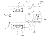
- FIG. 1 is a circuit diagram of a refrigeration cycle apparatus including an outdoor unit according to Embodiment 1 of the present invention.
- the refrigeration cycle apparatus 100 is an air conditioner. Even if the refrigeration cycle apparatus 100 is a device other than an air conditioner (for example, a heat pump cycle apparatus), the outdoor unit 110 according to Embodiment 1 can be applied.
- the refrigeration cycle apparatus 100 includes a refrigerant circuit 50 through which refrigerant circulates.
- the refrigerant circuit 50 is configured by connecting the compressor 1, the flow path switching device 2, the outdoor heat exchanger 10, the expansion valve 3, and the indoor heat exchanger 4 through a refrigerant pipe.
- the compressor 1 compresses the low-pressure gas refrigerant sucked from the suction port and discharges it from the discharge port 1a as a high-pressure gas refrigerant.
- the compressor 1 according to the first embodiment is provided with a suction muffler 1b that separates liquid refrigerant and gas refrigerant at the suction port.
- the flow path switching device 2 is, for example, a four-way valve, and is connected to the discharge port 1a of the compressor 1 through a refrigerant pipe. The flow path switching device 2 switches the inflow destination of the high-pressure gas refrigerant discharged from the compressor 1 to the outdoor heat exchanger 10 or the indoor heat exchanger 4.
- the outdoor heat exchanger 10 operates as a condenser during cooling, and dissipates the refrigerant compressed by the compressor 1.
- the outdoor heat exchanger 10 operates as an evaporator during heating, and heats the refrigerant by exchanging heat between the outdoor air and the refrigerant expanded by the expansion valve 3.
- the outdoor heat exchanger 10 according to Embodiment 1 is a fin tube heat exchanger, for example, and has the following configuration.
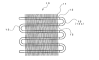
- FIG. 2 is a side view showing the outdoor heat exchanger according to Embodiment 1 of the present invention.
- the outdoor heat exchanger 10 includes a plurality of fins 11 that are arranged in parallel at a predetermined interval and a plurality of heat transfer tubes 12 that are arranged in parallel at a predetermined interval and penetrate the fins 11.
- the outdoor heat exchanger 10 also has a bent portion 13 that connects the two heat transfer tubes 12.
- the bent portion 13 is formed integrally with the two heat transfer tubes 12 by bending one pipe into a hairpin shape.
- the bending part 13 may be comprised with the U vent 13a separate from the heat exchanger tube 12.
- FIG. The U vent 13a is connected to the two heat transfer tubes 12 by brazing.
- the expansion valve 3 expands the refrigerant radiated by the condenser, that is, the refrigerant flowing into the expansion valve 3.
- the indoor heat exchanger 4 operates as a condenser during heating, and dissipates the refrigerant compressed by the compressor 1.
- the indoor heat exchanger 4 operates as an evaporator during cooling, and heats the refrigerant by exchanging heat between the indoor air and the refrigerant expanded by the expansion valve 3.
- the indoor heat exchanger 4 is, for example, a fin tube type heat exchanger. Note that when the refrigeration cycle apparatus 100 performs only one of cooling and heating, the flow path switching device 2 is not necessary.
- the refrigerant circulating in the refrigerant circuit 50 is a mixed refrigerant obtained by mixing 1,1,2-trifluoroethylene (HFO-1123) and another refrigerant different from the HFO-1123. used.
- a mixed refrigerant of HFO-1123 and difluoromethane (R32) can be used.
- the other refrigerant includes 2,3,3,3-tetrafluoropropene (R1234yf), trans-1,3,3,3-tetrafluoropropene (R1234ze (E)), cis-1 , 3,3,3-tetrafluoropropene (R1234ze (Z)), 1,1,1,2-tetrafluoroethane (R134a), 1,1,1,2,2-pentafluoroethane (R125) May be.
- at least two of these refrigerants may be adopted and mixed with HFO-1123.
- Each component of the refrigerant circuit 50 described above is housed in the outdoor unit 110 or the indoor unit 120.
- the indoor heat exchanger 4 is housed in the indoor unit 120.
- the compressor 1, the flow path switching device 2, the outdoor heat exchanger 10, and the refrigerant pipe connecting them are housed in the outdoor unit 110.
- the refrigerant pipe connecting them is the “pipe housed in the casing of the outdoor unit” in the present invention.
- the heat transfer tube 12, the bent portion 13, and the U vent 13a constituting the outdoor heat exchanger 10 are also “piping accommodated in the casing of the outdoor unit” in the present invention.
- the expansion valve 3 is housed in the outdoor unit 110 or the indoor unit 120. In FIG. 1, the example which accommodated the expansion valve 3 in the outdoor unit 110 is shown.
- the outdoor unit 110 and the indoor unit 120 can be connected and disconnected by the on-off valve 55 provided in the refrigerant circuit 50. That is, the outdoor unit 110 and the indoor unit 120 can be connected by the on-off valve 55 after being installed at the installation location.
- the outdoor unit 110 is installed at the installation location with the mixed refrigerant sealed in the outdoor unit 110 and the on-off valve 55 closed.
- the indoor unit 120 is installed in an installation location. Thereafter, the outdoor unit 110 and the indoor unit 120 are connected by the opening / closing valve 55 and the opening / closing valve 55 is opened. Thereby, the mixed refrigerant can be circulated in the refrigerant circuit 50, and the refrigeration cycle apparatus 100 can be used.
- FIG. 3 is a cross-sectional view showing the outdoor unit according to Embodiment 1 of the present invention from above.
- a specific arrangement of each component housed in the outdoor unit 110 will be described with reference to FIG.
- the outdoor unit 110 includes a substantially cuboid casing 111 formed of a plate such as a steel plate.
- the inside of the casing 111 is partitioned into a machine chamber 113 and a blower chamber 114 by a partition plate 112 that is a plate such as a steel plate.
- the housing 111 includes a machine room 113 and a blower room 114.
- a suction port 114a is formed in the back surface portion and the left side surface portion, and an air outlet 114b is formed in the front surface portion.
- the outdoor heat exchanger 10 is accommodated in the blower chamber 114 so that the fin 11 faces the suction port 114a. Further, the blower chamber 114 is provided with a blower 20 that is, for example, a propeller fan, facing the air outlet 114b. That is, when the blower 20 is driven, outdoor air is sucked into the blower chamber 114 from the suction port 114a and blown out from the blower outlet 114b. The air sucked into the blower chamber 114 exchanges heat with the mixed refrigerant flowing through the outdoor heat exchanger 10 when passing through the outdoor heat exchanger 10.
- a blower 20 that is, for example, a propeller fan
- the bent portion 13 of the outdoor heat exchanger 10 is disposed at a position not facing the suction port 114a. Specifically, as shown in FIG. 2, bent portions 13 are formed at both ends of the outdoor heat exchanger 10. The bent portion 13 at one end is disposed in front of the suction port 114 a formed on the left side surface portion of the blower chamber 114. That is, the outdoor unit 110 according to the first embodiment includes the plate 111d that forms the front side portion of the left side surface portion of the air blowing chamber 114 and the air flow between the bent portion 13 and the outside of the casing 111 of the outdoor unit 110. And a plate 111e constituting the left side portion of the front surface of the chamber 114.
- the bent portion 13 at the other end is housed in the machine room 113. That is, the outdoor unit 110 according to Embodiment 1 includes the plates 111a, 111b, 111c and the partition plate 112 that constitute the machine room 113 between the bent portion 13 and the outside of the casing 111 of the outdoor unit 110. It has. In the first embodiment, the bent portion 13 on the side accommodated in the machine room 113 is the U vent 13a.
- the machine room 113 also stores the compressor 1, the flow path switching device 2, and the like.
- the mixed refrigerant circulating through the refrigerant circuit 50 is expanded when the mixed refrigerant from the discharge port 1a of the compressor 1 to the inlet of the expansion valve 3 is on the high pressure side.
- the mixed refrigerant from the outlet of the valve 3 to the inlet of the compressor 1 is on the low pressure side.
- the ratio of HFO-1123 in the mixed refrigerant is 1 wt% or more and 35 wt% or less.
- the pressure on the high pressure side of the mixed refrigerant in the refrigerant circuit 50 is approximately 4 MPa or less regardless of the type of other refrigerant different from HFO-1123.
- the pressure on the high-pressure side of the mixed refrigerant in the refrigerant circuit 50 may abnormally increase.
- the high-temperature and high-pressure gas refrigerant flowing in the outdoor heat exchanger 10 cannot be condensed, and mixing in the refrigerant circuit 50
- the pressure on the high pressure side of the refrigerant rises abnormally.
- HFO-1123 contained in the mixed refrigerant diffuses due to a disproportionation reaction in a high temperature and high pressure state. Therefore, for example, when HFO-1123 is ignited from an ignition source in the compressor 1 (motor, wiring for supplying power to the motor, etc.), the disproportionation reaction of HFO-1123 diffuses as a chain reaction, and the disproportionation occurs. There is a concern that an explosion may occur due to the chemical reaction.
- the outdoor unit 110 according to the first embodiment is provided with the fracture induction structure 30 having a lower pressure resistance than the other part of the piping constituting the refrigerant circuit 50 at the bent portion 13 of the outdoor heat exchanger 10.
- the fracture induction structure 30 according to the first embodiment has the following configuration. In the following, an example in which the U vent 13a is provided with the fracture guiding structure 30 will be described.
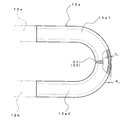
- FIG. 4 is a side view showing the U vent according to Embodiment 1 of the present invention.
- FIG. 4 shows a part as a cross section.
- the breakage guiding structure 30 according to the first embodiment has a notch structure having a notch 31.
- This notch 31 is formed in the outer periphery of piping, for example in the perimeter.
- the U vent 13a which is the bent portion 13 is configured to be broken, so that the break can be made on a small scale, and there can be no or few scattered objects.
- the U vent 13a is observed in the state shown in FIG. That is, for convenience, the heat transfer tube 12 connected to the upper end of the U vent 13a is referred to as a heat transfer tube 12a, the heat transfer tube 12 connected to the lower end of the U vent 13a is referred to as a heat transfer tube 12b, and the U vent 13a.
- a portion on the upper side of the notch 31 is referred to as an upper portion 13a1
- a portion of the U vent 13a on the lower side of the notch 31 is referred to as a lower portion 13a2.
- the lower portion 13a2 is pushed upward by the reaction force of the heat transfer tube 12b, which is a straight pipe. For this reason, when the notch 31 is broken, the movement of the upper portion 13a1 and the lower portion 13a2 of the U vent 13a is reduced, and the breakage of the U vent 13a can be reduced. In addition, since the movement of the upper portion 13a1 and the lower portion 13a2 of the U vent 13a is reduced, the upper portion 13a1 and the lower portion 13a2 can be prevented from interfering with nearby components, so that there is no or little scattered matter. You can also.
- the U vent 13a is housed in the machine room 113. That is, the plates 111 a, 111 b, 111 c and the partition plate 112 constituting the machine room 113 are provided between the U vent 13 a having the notch 31 and the outside of the casing 111 of the outdoor unit 110. For this reason, it can also prevent that the mixed refrigerant blown out from the notch 31 which is a fracture
- the notch 31 does not penetrate the U vent 13a and has a depth of 30% or more of the thickness of the portion where the notch 31 is not formed in the U vent 13a. In other words, it is preferable that 0.3t ⁇ d ⁇ t, where t is the thickness of the U vent 13a where the notch 31 is not formed, and d is the depth of the notch 31.
- the breakage induction structure 30 breaks at 10 MPa to 15 MPa.
- the resin that covers the motor winding of the compressor 1 and the wiring for supplying power to the motor generally has a heat resistance of about 230 ° C. to 250 ° C.
- the temperature at which the resin melts and the winding or wiring is exposed is assumed to be about 300 ° C. Therefore, the inventors diffused the disproportionation reaction of HFO-1123 as a chain reaction at what pressure when a mixed refrigerant having an HFO-1123 ratio of 35 wt% or less is used in an environment of 300 ° C. I verified it.
- the disproportionation reaction of HFO-1123 diffuses as a chain reaction when the pressure is higher than 15 MPa. It has also been found that when the pressure on the high-pressure side of the mixed refrigerant in the refrigerant circuit 50 abnormally increases as described above, the pressure on the high-pressure side may increase to around 10 MPa. Therefore, when the ratio of HFO-1123 in the mixed refrigerant is 35 wt% or less as in the first embodiment, it is preferable that the breakage induction structure 30 breaks at 10 MPa to 15 MPa.
- the notch 31 that is the breakage induction structure 30 is provided in the bent portion 13 housed in the machine room 113 among the bent portion 13 of the outdoor heat exchanger 10. Not only this but you may provide the notch 31 in the bending part 13 arrange
- FIG. Between the bent portion 13 and the outside of the casing 111 of the outdoor unit 110, as described above, the plate 111d constituting the front side portion of the left side surface portion of the blower chamber 114 and the left side portion of the front portion of the blower chamber 114 are provided. The board 111e which comprises this is provided.
- the mixed refrigerant blown out from the notch 31 can be prevented from being ejected to the outside of the outdoor unit 110.
- the blower chamber 114 is formed with large openings such as an inlet 114a and an outlet 114b.
- the machine room 113 does not have such a large opening. For this reason, when the notch 31 is provided in the bent portion 13 accommodated in the machine room 113, the mixed refrigerant blown out from the notch 31 can be more prevented from being ejected to the outside of the outdoor unit 110.
- FIG. 1 a notch structure is adopted as the fracture guide structure 30.
- the structure of the fracture induction structure 30 is not limited to the notch structure, and may be the following structure, for example.
- items that are not particularly described are the same as those in the first embodiment, and the same functions and configurations are described using the same reference numerals.
- FIG. 5 is a cross-sectional view showing a bent portion of the outdoor heat exchanger according to Embodiment 2 of the present invention.
- FIG. 5A shows a cross section of a thin portion 32 described later.
- FIG. 5B shows a cross section of a portion other than the thin portion 32 in the bent portion 13.
- a thin portion 32 having a smaller thickness than other portions of the bent portion 13 is formed in a part of the bent portion 13 of the outdoor heat exchanger 10 according to the second embodiment.
- the thin-walled portion 32 is the fracture induction structure 30.
- the fracture guide structure 30 according to the second embodiment has a thin structure.
- the pressure resistance of the thin portion 32 is lower than the pressure resistance of the bent portion 13 other than the thin portion 32. Therefore, when the pressure on the high pressure side of the mixed refrigerant in the refrigerant circuit 50 rises abnormally, the thin portion 32 is broken, so that the mixed refrigerant can be discharged to the outside of the pipe, and the pressure in the refrigerant circuit 50 is released. Can do. For this reason, even when the thin-walled portion 32 has the fracture inducing structure 30, it is possible to prevent the disproportionation reaction of HFO-1123 from diffusing as a chain reaction, and to prevent an explosion due to the disproportionation reaction.
- the thin portion 32 preferably has a thinning ratio of 70% or less.
- the thinning rate is defined as t3 / t4, where t3 is the thickness of the thin portion 32 and t4 is the thickness of the bent portion 13 other than the thin portion 32. That is, it is preferable that the thin portion 32 satisfy t3 / t4 ⁇ 0.7.
- the thickness is reduced over the entire circumference of the pipe, and the thin portion 32 is formed over the entire circumference of the pipe.
- the present invention is not limited to this, and when the bent portion 13 is viewed in cross section, the thickness of a part of the entire circumference may be reduced, and the portion may be the thin portion 32.
- the structure of the breakage induction structure 30 shown in the second embodiment may be combined with the structure of the breakage induction structure 30 shown in the first embodiment. That is, the notch 31 may be formed in the thin portion 32 to form the breakage induction structure 30.
- the breakage induction structure 30 can be broken at a pressure closer to the target value, and the pressure range in which the breakage induction structure 30 breaks. The width of can be reduced. That is, the operation of the refrigeration cycle apparatus 100 can be further stabilized.
- Embodiment 3 The structure of the breakage induction structure 30 is not limited to the first and second embodiments, and may be the following structure, for example.
- items that are not particularly described are the same as those in Embodiment 1, and the same functions and configurations are described using the same reference numerals.
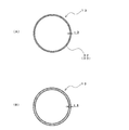
- FIG. 6 is a cross-sectional view showing a bent portion of an outdoor heat exchanger according to Embodiment 3 of the present invention.
- FIG. 6A shows a cross section of a flat portion 33 to be described later.
- FIG. 6B shows a cross section of a portion other than the flat portion 33 in the bent portion 13.
- a part of the bent portion 13 of the outdoor heat exchanger 10 according to the third embodiment is a flat portion 33 having a substantially elliptical cross section at the outer peripheral portion.
- portions other than the flat portion 33 in the bent portion 13 are formed in a circular tube shape, and a cross section of the outer peripheral portion is circular. And in this Embodiment 3, this flat part 33 is made into the fracture
- the fracture guide structure 30 according to the third embodiment has a flat structure.
- the pressure resistance of the flat portion 33 is lower than the pressure resistance of the circular pipe portion that is a portion other than the flat portion 33 in the bent portion 13. Therefore, when the pressure on the high pressure side of the mixed refrigerant in the refrigerant circuit 50 rises abnormally, the flat portion 33 is broken, so that the mixed refrigerant can be discharged to the outside of the pipe, and the pressure in the refrigerant circuit 50 is released. Can do. For this reason, even when the flat portion 33 has the fracture inducing structure 30, it is possible to prevent the disproportionation reaction of HFO-1123 from diffusing as a chain reaction, and to prevent an explosion due to the disproportionation reaction.
- the flat portion 33 preferably has a flatness ratio of 10% or more.
- the flattening ratio is defined by the length d1 of the long radius in the cross section of the outer peripheral portion of the flat portion 33, the diameter d2 of the short radius in the cross section of the outer peripheral portion of the flat portion 33, When d3, it is defined by (d1-d2) / d3. That is, the flat portion 33 is preferably (d1 ⁇ d2) /d3 ⁇ 0.1.
- the entire bent portion 13 may be the flat portion 33.
- the structure of the breakage induction structure 30 shown in the third embodiment may be combined with the structure of the breakage induction structure 30 shown in the first and second embodiments.
- at least one of the thin portion 32 and the notch 31 may be formed on the flat portion 33 to form the fracture induction structure 30.
- Embodiment 4 The structure of the fracture guiding structure 30 is not limited to the first to third embodiments, and may be the following structure, for example.
- items not particularly described are the same as those in the first embodiment, and the same functions and configurations are described using the same reference numerals.
- the bent portion 13 of the outdoor heat exchanger 10 according to the fourth embodiment is made of metal. And the bending part 13 of the outdoor heat exchanger 10 which concerns on this Embodiment 4 has the coarse part in which the particle size of the crystal
- the pressure resistance of the coarse portion is lower than the pressure resistance of the bent portion 13 other than the coarse portion. Therefore, when the pressure on the high pressure side of the mixed refrigerant in the refrigerant circuit 50 rises abnormally, the coarse portion breaks, so that the mixed refrigerant can be discharged to the outside of the pipe, and the pressure in the refrigerant circuit 50 can be released. it can. For this reason, even when the coarse portion has the fracture inducing structure 30, it is possible to prevent the disproportionation reaction of HFO-1123 from diffusing as a chain reaction, and to prevent explosion due to the disproportionation reaction.
- the structure of the breakage induction structure 30 shown in the fourth embodiment may be combined with the structure of the breakage induction structure 30 shown in the first to third embodiments.
- at least one of the flat part 33, the thin part 32, and the notch 31 may be formed in the coarse part to form the fracture induction structure 30.
- Embodiment 5 When providing the fracture
- items that are not particularly described are the same as those in the first embodiment, and the same functions and configurations are described using the same reference numerals.
- FIG. 7 is a side view showing a U vent according to Embodiment 5 of the present invention.
- a tube expansion portion 34 is formed by expanding the end portion.
- the heat transfer pipe 12 and the pipe expansion part 34 are brazed, and the heat transfer pipe 12 and the U vent 13a are connected.
- the expanded pipe portion 34 is the fracture induction structure 30.
- the pipe expansion part 34 When the pipe expansion part 34 is formed by expanding both ends of the U vent 13a, the thickness of the pipe expansion part 34 becomes thinner than the thickness of the bent part 13 other than the pipe expansion part 34. For this reason, the pressure resistance of the pipe expansion portion 34 is lower than the pressure resistance of the bent portion 13 other than the pipe expansion portion 34. Therefore, when the pressure on the high pressure side of the mixed refrigerant in the refrigerant circuit 50 rises abnormally, the expanded pipe portion 34 is broken, so that the mixed refrigerant can be discharged to the outside of the pipe, and the pressure in the refrigerant circuit 50 is released. Can do.
- the expanded pipe portion 34 is the breakage induction structure 30, it is possible to prevent the disproportionation reaction of HFO-1123 from diffusing as a chain reaction and to prevent an explosion due to the disproportionation reaction.
- the end portion of the expanded pipe portion 34 since the heat exchanger tube 12 is inserted, the end portion of the expanded pipe portion 34 has a double tube structure. For this reason, the expanded pipe portion 34 is broken at the base portion (the Z portion in FIG. 7) of the expanded tube portion 34 not having the double tube structure.
- the pipe expansion portion 34 has a thinning ratio of 70% or less.
- the thinning rate is defined as t1 / t2, where the thickness of the expanded portion 34 is t1, and the thickness of the bent portion 13 other than the expanded portion 34 is t2. That is, it is preferable that the pipe expansion part 34 is t1 / t2 ⁇ 0.7.
- voltage resistant difference becomes clear and the fracture
- the structure of the breakage induction structure 30 shown in the fifth embodiment may be combined with the structure of the breakage induction structure 30 shown in the first to fourth embodiments.
- at least one of a coarse portion, a flat portion 33, a thin portion 32, and a notch 31 may be formed in the tube expansion portion 34 to form the breakage induction structure 30.
- Embodiment 6 The location where the fracture induction structure 30 according to the present invention is provided is not limited to the bent portion 13 of the outdoor heat exchanger 10.
- the breakage induction structure 30 may be provided at the following locations.
- items that are not particularly described are the same as those in any of the first to fifth embodiments, and the same functions and configurations are described using the same reference numerals.
- FIG. 8 is a circuit diagram of a refrigeration cycle apparatus including an outdoor unit according to Embodiment 6 of the present invention.
- the outdoor unit 110 according to the sixth embodiment is connected to a refrigerant pipe connecting the discharge port 1a of the compressor 1 and the flow path switching device 2, that is, between the discharge port 1a of the compressor 1 and the flow path switching device 2.
- a bending portion 6 is provided.
- the refrigerant pipe that connects the discharge port 1a of the compressor 1 and the flow path switching device 2 is the “pipe housed in the casing of the outdoor unit” in the present invention. As can be seen from FIG.
- the bending portion 6 provided at the connection portion between the compressor 1 and the flow path switching device 2 is also provided. Further, it is provided in the machine room 113. That is, the plates 111 a, 111 b, 111 c and the partition plate 112 constituting the machine room 113 are provided between the bent portion 6 and the outside of the casing 111 of the outdoor unit 110.
- the bent portion 6 is formed similarly to the bent portion 13 of the outdoor heat exchanger 10 shown in the first to fifth embodiments, and the bent portion 6 is shown in the first to fifth embodiments.
- the breakage induction structure 30 By providing the breakage induction structure 30, the same effect as in the first to fifth embodiments can be obtained.
- the breakage induction structure 30 in the bent portion 6 as in the sixth embodiment. That is, when the refrigeration cycle apparatus 100 performs a heating operation, the outdoor heat exchanger 10 operates as an evaporator. Therefore, when the breakage induction structure 30 is provided at the bent portion 13 of the outdoor heat exchanger 10 as in the first to fifth embodiments, the breakage induction structure 30 is placed on the low pressure side in the refrigerant circuit 50 during heating operation. Will be placed. Therefore, during the heating operation, the breakage induction structure 30 does not operate, that is, does not break.
- the heating operation can be performed.
- the breakage induction structure 30 is disposed on the high pressure side of the refrigerant circuit 50. For this reason, the breakage induction structure 30 can be operated in both the heating operation and the cooling operation by providing the breakage induction structure 30 as in the sixth embodiment.
Landscapes
- Engineering & Computer Science (AREA)
- Mechanical Engineering (AREA)
- General Engineering & Computer Science (AREA)
- Physics & Mathematics (AREA)
- Thermal Sciences (AREA)
- Chemical & Material Sciences (AREA)
- Combustion & Propulsion (AREA)
- Other Air-Conditioning Systems (AREA)
- Heat-Exchange Devices With Radiators And Conduit Assemblies (AREA)
Abstract
Description
・R744:動作圧力が非常に高いため、耐圧確保の課題がある。また、臨界温度が31℃と低いため、空気調和機用途での性能の確保が課題となる。
・R717:高毒性であるため、安全確保の課題がある。
・R290:強燃性であるため、安全確保の課題がある。
・R1234yf及びR1234ze:低動作圧で体積流量が大きくなるため、圧力損失増大による性能低下の課題がある。 Since these low GWP refrigerants have the following problems, it is difficult to apply them to general air conditioners.
R744: Since the operating pressure is very high, there is a problem of ensuring a withstand pressure. Moreover, since critical temperature is as low as 31 degreeC, ensuring the performance in an air conditioner use becomes a subject.
-R717: Since it is highly toxic, there is a problem of ensuring safety.
-R290: Since it is highly flammable, there is a problem of ensuring safety.
R1234yf and R1234ze: Since the volume flow rate becomes large at a low operating pressure, there is a problem of performance degradation due to an increase in pressure loss.
・動作圧力が高く、冷媒の体積流量が小さいため、圧力損失が小さく、性能を確保しやすい。
・GWPが1未満であり、地球温暖化対策として優位性が高い。 As a refrigerant for solving the above problems, there is 1,1,2-trifluoroethylene (HFO-1123) (see, for example, Patent Document 1). This refrigerant has the following advantages in particular.
-Since the operating pressure is high and the volume flow rate of the refrigerant is small, the pressure loss is small and it is easy to ensure performance.
-GWP is less than 1 and is highly advantageous as a measure against global warming.
(1)高温高圧の状態において、着火エネルギーが加わると、爆発が発生する(例えば、非特許文献1参照)。 HFO-1123 has the following problems.
(1) When ignition energy is applied in a high temperature and high pressure state, an explosion occurs (for example, see Non-Patent Document 1).
(1a)冷凍サイクル装置(特に、圧縮機)の内部に着火エネルギー(高温部)が発生し、不均化反応が起こる。
(1b)高温高圧の状態において、不均化反応が連鎖して拡散する。 Regarding the above problems, it has become clear that an explosion occurs due to the chain of disproportionation reaction. The conditions under which this phenomenon occurs are the following two points.
(1a) Ignition energy (high temperature part) is generated inside the refrigeration cycle apparatus (particularly the compressor), and a disproportionation reaction occurs.
(1b) In a state of high temperature and high pressure, disproportionation reactions are chained and diffused.
また、本発明に係る室外機は、破断誘導構造を曲がり部に備えているので、小規模で飛散物が無い又は少ない状態で破断誘導構造を破断させることができる。さらに、本発明に係る室外機は、破断誘導構造と前記筐体の外部との間に板を備えているので、破断箇所から吹き出した混合冷媒が室外機の外部に噴出することも防止できる。
したがって、本発明に係る室外機を用いて冷凍サイクル装置を構成することにより、HFO-1123を使用しても安全性を確保することができる冷凍サイクル装置を得ることができる。 By configuring the refrigeration cycle apparatus using the outdoor unit according to the present invention, when the pressure of the mixed refrigerant rises abnormally, the pipe breaks at the break induction structure portion, so the mixed refrigerant can be discharged to the outside of the pipe. . Therefore, the disproportionation reaction of 1,1,2-trifluoroethylene (HFO-1123) can be prevented from diffusing as a chain reaction, and an explosion due to the disproportionation reaction can be prevented.
Moreover, since the outdoor unit which concerns on this invention is equipped with the fracture | rupture induction | guidance | derivation structure in the bending part, it can fracture | rupture a fracture | rupture induction | guidance | derivation structure in a state where there is little or no scattered matter on a small scale. Furthermore, since the outdoor unit according to the present invention includes a plate between the breakage induction structure and the outside of the housing, it is possible to prevent the mixed refrigerant blown out from the broken part from being blown out of the outdoor unit.
Accordingly, by configuring the refrigeration cycle apparatus using the outdoor unit according to the present invention, it is possible to obtain a refrigeration cycle apparatus that can ensure safety even when HFO-1123 is used.
図1は、本発明の実施の形態1に係る室外機を備えた冷凍サイクル装置の回路図である。
本実施の形態1において、冷凍サイクル装置100は、空気調和機である。なお、冷凍サイクル装置100が空気調和機以外の機器(例えば、ヒートポンプサイクル装置)であっても、本実施の形態1に係る室外機110を適用することができる。
FIG. 1 is a circuit diagram of a refrigeration cycle apparatus including an outdoor unit according to
In
室外熱交換器10は、規定間隔を開けて並設された複数のフィン11と、規定間隔を開けて並設され、フィン11を貫通する複数の伝熱管12とを有する。また、室外熱交換器10は、2つの伝熱管12を接続する曲がり部13を有する。例えば、曲がり部13は、1本の配管をヘアピン状に曲げることにより、2つの伝熱管12と一体で形成される。また例えば、曲がり部13は、伝熱管12とは別体のUベント13aで構成される場合もある。Uベント13aは、2つの伝熱管12とロウ付けにより接続される。 FIG. 2 is a side view showing the outdoor heat exchanger according to Embodiment 1 of the present invention.
The
以下、図3を用いて、室外機110に収納されている各構成の具体的な配置について説明する。 FIG. 3 is a cross-sectional view showing the outdoor unit according to
Hereinafter, a specific arrangement of each component housed in the
(1)室外熱交換器10が凝縮器として動作している状態において、送風機20が停止した場合、室外熱交換器10内を流れる高温高圧のガス冷媒が凝縮できず、冷媒回路50中の混合冷媒の高圧側の圧力が異常上昇する。
(2)室外熱交換器10が凝縮器として動作している状態において、室外機110の吸込口114a又は吹出口114bの近傍に物が置かれた場合、送風室114を通過する室外空気の量が減少するため、室外熱交換器10内を流れる高温高圧のガス冷媒が凝縮できず、冷媒回路50中の混合冷媒の高圧側の圧力が異常上昇する。
(3)開閉弁55を開き忘れた状態で冷凍サイクル装置100の運転を開始した結果、冷媒回路50中の混合冷媒の高圧側の圧力が異常上昇する。
(4)経年劣化等によって冷媒回路50内が詰まり、冷媒回路50中の混合冷媒の高圧側の圧力が異常上昇する。 Here, when the
(1) In the state where the
(2) When the
(3) As a result of starting the operation of the
(4) The
図4に示すように、本実施の形態1に係る破断誘導構造30は、切り欠き31を有する切り欠き構造となっている。この切り欠き31は、配管の外周に、例えば全周において形成されている。これにより、冷媒回路50中の混合冷媒の高圧側の圧力が異常上昇した際、破断誘導構造30が破断するため、混合冷媒を配管外部に放出することができ、冷媒回路50中の圧力を開放することができる。このため、HFO-1123の不均化反応が連鎖反応として拡散することを防止でき、不均化反応による爆発を防止できる。 FIG. 4 is a side view showing the U vent according to
As shown in FIG. 4, the
実施の形態1では、破断誘導構造30として切り欠き構造を採用した。しかしながら、破断誘導構造30の構造は、切り欠き構造に限定されるものではなく、例えば次のような構造としてもよい。なお、本実施の形態2において、特に記述しない項目については実施の形態1と同様とし、同一の機能や構成については同一の符号を用いて述べることとする。
In the first embodiment, a notch structure is adopted as the
本実施の形態2に係る室外熱交換器10の曲がり部13の一部には、該曲がり部13の他の箇所よりも肉厚の薄い薄肉部32が形成されている。そして、本実施の形態2では、該薄肉部32を破断誘導構造30としている。換言すると、本実施の形態2に係る破断誘導構造30は、薄肉構造となっている。 FIG. 5 is a cross-sectional view showing a bent portion of the outdoor heat exchanger according to
A
ここで、薄肉部32は、薄肉化率を70%以下にすることが好ましい。薄肉化率は、薄肉部32の肉厚をt3、曲がり部13における薄肉部32以外の箇所の肉厚をt4とした場合、t3/t4で定義するものとする。つまり、薄肉部32は、t3/t4≦0.7とすることが好ましい。このように薄肉部32の薄肉化率を設定することにより、耐圧差が明確となり、破断誘導構造30を他の配管部分よりも確実に早く破断させることができる。薄肉部32の薄肉化率の下限値は、破断誘導構造30が破断する圧力の下限値に応じて、適宜決定すればよい。[Correction based on Rule 91 20.06.2017]
Here, the
破断誘導構造30の構造は、実施の形態1,2に限定されるものではなく、例えば次のような構造としてもよい。なお、本実施の形態3において、特に記述しない項目については実施の形態1と同様とし、同一の機能や構成については同一の符号を用いて述べることとする。
The structure of the
本実施の形態3に係る室外熱交換器10の曲がり部13の一部は、外周部の断面が略楕円形状となった扁平部33となっている。また、曲がり部13における扁平部33以外の箇所は、円管状に形成されており、外周部の断面が円状になっている。そして、本実施の形態3では、該扁平部33を破断誘導構造30としている。換言すると、本実施の形態3に係る破断誘導構造30は、扁平構造となっている。 FIG. 6 is a cross-sectional view showing a bent portion of an outdoor heat exchanger according to
A part of the
ここで、扁平部33は、扁平率を10%以上にすることが好ましい。扁平率は、扁平部33の外周部の断面における長半径をd1、扁平部33の外周部の断面における短半径をd2、曲がり部13における扁平部33以外の箇所の外周部の断面の直径をd3とした場合、(d1-d2)/d3で定義するものとする。つまり、扁平部33は、(d1-d2)/d3≧0.1とすることが好ましい。このように扁平部33の扁平率を設定することにより、耐圧差が明確となり、破断誘導構造30を他の配管部分よりも確実に早く破断させることができる。扁平部33の扁平率の上限値は、破断誘導構造30が破断する圧力の下限値に応じて、適宜決定すればよい。[Correction based on Rule 91 20.06.2017]
Here, the
破断誘導構造30の構造は、実施の形態1~実施の形態3に限定されるものではなく、例えば次のような構造としてもよい。なお、本実施の形態4において、特に記述しない項目については実施の形態1と同様とし、同一の機能や構成については同一の符号を用いて述べることとする。
The structure of the
Uベント13aに破断誘導構造30を設ける場合、例えば次のような構造としてもよい。なお、本実施の形態5において、特に記述しない項目については実施の形態1と同様とし、同一の機能や構成については同一の符号を用いて述べることとする。
When providing the fracture | rupture induction | guidance |
本実施の形態5に係るUベント13aの例えば両端部には、該端部を押し広げた拡管部34が形成されている。そして、拡管部34に伝熱管12を挿入した状態で、伝熱管12と拡管部34とをロウ付けし、伝熱管12とUベント13aを接続している。そして、本実施の形態5では、該拡管部34を破断誘導構造30としている。 FIG. 7 is a side view showing a U vent according to
For example, at both end portions of the U vent 13a according to the fifth embodiment, a
ここで、拡管部34は、薄肉化率を70%以下にすることが好ましい。薄肉化率は、拡管部34の肉厚をt1、曲がり部13における拡管部34以外の箇所の肉厚をt2とした場合、t1/t2で定義するものとする。つまり、拡管部34は、t1/t2≦0.7とすることが好ましい。このように拡管部34の薄肉化率を設定することにより、耐圧差が明確となり、破断誘導構造30を他の配管部分よりも確実に早く破断させることができる。拡管部34の薄肉化率の下限値は、破断誘導構造30が破断する圧力の下限値に応じて、適宜決定すればよい。[Correction based on Rule 91 20.06.2017]
Here, it is preferable that the
本発明に係る破断誘導構造30が設けられる箇所は、室外熱交換器10の曲がり部13に限定されるものではない。例えば、次のような箇所に破断誘導構造30を設けてもよい。なお、本実施の形態6において、特に記述しない項目については実施の形態1~実施の形態5のいずれかと同様とし、同一の機能や構成については同一の符号を用いて述べることとする。
The location where the
本実施の形態6に係る室外機110は、圧縮機1の吐出口1aと流路切替装置2とを接続する冷媒配管に、つまり圧縮機1の吐出口1aと流路切替装置2との間に、曲がり部6を備えている。上述のように、圧縮機1の吐出口1aと流路切替装置2とを接続する冷媒配管は、本発明における「室外機の筐体に収納された配管」となる。また、図3からわかるように、圧縮機1及び流路切替装置2は機械室113に設けられているため、圧縮機1と流路切替装置2との接続箇所に設けられた曲がり部6もまた、機械室113に設けられている。つまり、曲がり部6と室外機110の筐体111の外部との間に、機械室113を構成する板111a,111b,111cと仕切板112とを備えている。 FIG. 8 is a circuit diagram of a refrigeration cycle apparatus including an outdoor unit according to
The
Claims (16)
- 1,1,2-トリフルオロエチレンを含む混合冷媒が循環する冷凍サイクル装置に用いられる室外機であって、
筐体と、
前記混合冷媒が流れる配管と、
を備え、
前記配管は、前記筐体に収納されて、曲がり部を有し、
該曲がり部は、前記配管の他の部分よりも耐圧が低い破断誘導構造を有し、
該破断誘導構造と前記筐体の外部との間に板を備えた室外機。 An outdoor unit used in a refrigeration cycle apparatus in which a mixed refrigerant containing 1,1,2-trifluoroethylene circulates,
A housing,
Piping through which the mixed refrigerant flows;
With
The pipe is housed in the housing and has a bent portion;
The bent portion has a fracture induction structure having a lower pressure resistance than the other portion of the pipe,
An outdoor unit including a plate between the breakage induction structure and the outside of the housing. - 前記筐体は、吸込口及び吹出口が形成された送風室と、該送風室とは仕切られた機械室とを備え、
前記破断誘導構造が前記機械室に収納されている請求項1に記載の室外機。 The housing includes a blower chamber in which a suction port and a blower outlet are formed, and a machine room partitioned from the blower chamber,
The outdoor unit according to claim 1, wherein the breaking guide structure is housed in the machine room. - 前記混合冷媒中の前記1,1,2-トリフルオロエチレンの比率が35wt%以下であり、
前記破断誘導構造は、10MPa~15MPaで破断する請求項1又は請求項2に記載の室外機。 A ratio of the 1,1,2-trifluoroethylene in the mixed refrigerant is 35 wt% or less;
The outdoor unit according to claim 1 or 2, wherein the breakage induction structure is broken at 10 to 15 MPa. - フィンと、該フィンを貫通し、前記配管の一部を構成する複数の伝熱管と、2つの前記伝熱管を接続する前記曲がり部と、を有する室外熱交換器を備えた請求項1~請求項3のいずれか一項に記載の室外機。 An outdoor heat exchanger having a fin, a plurality of heat transfer tubes that penetrate the fin and constitute a part of the pipe, and the bent portion that connects the two heat transfer tubes is provided. Item 4. The outdoor unit according to any one of Items 3.
- 前記曲がり部は、前記伝熱管とは別体に形成され、前記伝熱管にロウ付けされたUベントである請求項4に記載の室外機。 The outdoor unit according to claim 4, wherein the bent portion is a U vent formed separately from the heat transfer tube and brazed to the heat transfer tube.
- 前記Uベントの端部に、該端部を押し広げた拡管部が形成されており、
前記破断誘導構造は、該拡管部である請求項5に記載の室外機。 At the end of the U vent, a tube expansion portion is formed by expanding the end,
The outdoor unit according to claim 5, wherein the breakage induction structure is the tube expansion portion. - [規則91に基づく訂正 20.06.2017]
前記Uベントの前記拡管部の肉厚をt1、前記Uベントにおける前記拡管部以外の箇所の肉厚をt2とした場合、
t1/t2≦0.7である請求項6に記載の室外機。 [Correction based on Rule 91 20.06.2017]
When the thickness of the expanded portion of the U vent is t1, and the thickness of the U vent other than the expanded portion is t2,
The outdoor unit according to claim 6, wherein t1 / t2 ≦ 0.7. - 圧縮機と、
該圧縮機の吐出口と前記配管で接続され、前記圧縮機から吐出された前記混合冷媒の流入先を切り替える流路切替装置と、
を有し、
前記圧縮機の吐出口と前記流路切替装置との間に前記曲がり部を備えた請求項1~請求項3のいずれか一項に記載の室外機。 A compressor,
A flow path switching device that is connected to the discharge port of the compressor by the pipe and switches an inflow destination of the mixed refrigerant discharged from the compressor;
Have
The outdoor unit according to any one of claims 1 to 3, wherein the bent portion is provided between a discharge port of the compressor and the flow path switching device. - 前記破断誘導構造は、前記配管の外周に形成された切り欠きである請求項1~請求項8のいずれか一項に記載の室外機。 The outdoor unit according to any one of claims 1 to 8, wherein the break guide structure is a notch formed on an outer periphery of the pipe.
- 前記切り欠きは、前記配管を貫通せず、前記曲がり部における前記切り欠きが形成されていない箇所の肉厚の30%以上の深さである請求項9に記載の室外機。 The outdoor unit according to claim 9, wherein the notch has a depth of 30% or more of a thickness of a portion where the notch is not formed in the bent portion without penetrating the pipe.
- 前記曲がり部の一部に、該曲がり部の他の箇所よりも肉厚の薄い薄肉部が形成されており、
前記破断誘導構造は、該薄肉部である請求項1~請求項10のいずれか一項に記載の室外機。 A thin-walled portion that is thinner than other portions of the bent portion is formed in a part of the bent portion,
The outdoor unit according to any one of claims 1 to 10, wherein the breaking guide structure is the thin portion. - [規則91に基づく訂正 20.06.2017]
前記薄肉部の肉厚をt3、前記曲がり部における前記薄肉部以外の箇所の肉厚をt4とした場合、
t3/t4≦0.7である請求項11に記載の室外機。 [Correction based on Rule 91 20.06.2017]
When the thickness of the thin portion is t3 and the thickness of the bent portion other than the thin portion is t4,
The outdoor unit according to claim 11, wherein t3 / t4 ≦ 0.7. - 前記曲がり部に、外周部の断面が楕円形状の扁平部が形成されており、
前記破断誘導構造は、該扁平部である請求項1~請求項12のいずれか一項に記載の室外機。 A flat portion having an elliptical cross section at the outer periphery is formed in the bent portion,
The outdoor unit according to any one of claims 1 to 12, wherein the breaking guide structure is the flat portion. - [規則91に基づく訂正 20.06.2017]
前記曲がり部の一部に、前記扁平部が形成されており、
前記扁平部の外周部の断面における長半径をd1、前記扁平部の外周部の断面における短半径をd2、前記曲がり部における前記扁平部以外の箇所の外周部の断面の直径をd3とした場合、
(d1-d2)/d3≧0.1である請求項13に記載の室外機。 [Correction based on Rule 91 20.06.2017]
The flat part is formed in a part of the bent part,
When the long radius in the cross section of the outer peripheral portion of the flat portion is d1, the short radius in the cross section of the outer peripheral portion of the flat portion is d2, and the diameter of the cross section of the outer peripheral portion of the bent portion other than the flat portion is d3 ,
The outdoor unit according to claim 13, wherein (d1-d2) /d3≥0.1. - [規則91に基づく訂正 20.06.2017]
前記扁平部の外周部の断面における長半径をd1、前記扁平部の外周部の断面における短半径をd2とした場合、
(d1-d2)/{(d1+d2)/2}≧0.1である請求項13に記載の室外機。 [Correction based on Rule 91 20.06.2017]
When the long radius in the cross section of the outer peripheral portion of the flat portion is d1, and the short radius in the cross section of the outer peripheral portion of the flat portion is d2,
The outdoor unit according to claim 13, wherein (d1-d2) / {(d1 + d2) / 2} ≧ 0.1. - 前記曲がり部は金属製であり、
前記曲がり部の一部に、該曲がり部の他の箇所よりも結晶の粒径が大きい粗大部が形成されており、
前記破断誘導構造は、該粗大部である請求項1~請求項15のいずれか一項に記載の室外機。 The bent portion is made of metal,
A coarse part having a larger crystal grain size than other parts of the bent part is formed in a part of the bent part,
The outdoor unit according to any one of claims 1 to 15, wherein the breakage induction structure is the coarse portion.
Priority Applications (6)
| Application Number | Priority Date | Filing Date | Title |
|---|---|---|---|
| US16/072,033 US11105521B2 (en) | 2016-03-28 | 2016-03-28 | Outdoor unit |
| PCT/JP2016/059862 WO2017168503A1 (en) | 2016-03-28 | 2016-03-28 | Outdoor unit |
| JP2018507829A JP6639644B2 (en) | 2016-03-28 | 2016-03-28 | Outdoor unit |
| CN202210591371.6A CN114777216A (en) | 2016-03-28 | 2016-03-28 | Outdoor machine |
| CN201680083697.0A CN108885038A (en) | 2016-03-28 | 2016-03-28 | Outdoor unit |
| EP16896723.0A EP3438573B1 (en) | 2016-03-28 | 2016-03-28 | Outdoor unit |
Applications Claiming Priority (1)
| Application Number | Priority Date | Filing Date | Title |
|---|---|---|---|
| PCT/JP2016/059862 WO2017168503A1 (en) | 2016-03-28 | 2016-03-28 | Outdoor unit |
Publications (1)
| Publication Number | Publication Date |
|---|---|
| WO2017168503A1 true WO2017168503A1 (en) | 2017-10-05 |
Family
ID=59963641
Family Applications (1)
| Application Number | Title | Priority Date | Filing Date |
|---|---|---|---|
| PCT/JP2016/059862 WO2017168503A1 (en) | 2016-03-28 | 2016-03-28 | Outdoor unit |
Country Status (5)
| Country | Link |
|---|---|
| US (1) | US11105521B2 (en) |
| EP (1) | EP3438573B1 (en) |
| JP (1) | JP6639644B2 (en) |
| CN (2) | CN108885038A (en) |
| WO (1) | WO2017168503A1 (en) |
Cited By (2)
| Publication number | Priority date | Publication date | Assignee | Title |
|---|---|---|---|---|
| JP2018025326A (en) * | 2016-08-09 | 2018-02-15 | パナソニックIpマネジメント株式会社 | Refrigeration cycle device |
| WO2018193974A1 (en) * | 2017-04-20 | 2018-10-25 | Agc株式会社 | Heat cycle system |
Families Citing this family (3)
| Publication number | Priority date | Publication date | Assignee | Title |
|---|---|---|---|---|
| CN110494703A (en) * | 2017-03-31 | 2019-11-22 | 大金工业株式会社 | Air-conditioning device |
| DE112019000058T5 (en) * | 2019-08-07 | 2020-02-27 | Komatsu Ltd. | MIXING CONNECTION AND MOTOR |
| WO2023188386A1 (en) * | 2022-03-31 | 2023-10-05 | 三菱電機株式会社 | Heat exchanger and air conditioner |
Citations (12)
| Publication number | Priority date | Publication date | Assignee | Title |
|---|---|---|---|---|
| US1858280A (en) * | 1930-02-24 | 1932-05-17 | Perfection Stove Co | Safety blow-off device |
| JPH07332811A (en) * | 1994-06-09 | 1995-12-22 | Matsushita Refrig Co Ltd | Refrigerator, method for recovering refrigerant therefrom and method for modifying the same |
| JP2000130896A (en) * | 1998-10-29 | 2000-05-12 | Sanden Corp | Air conditioner equipped with safety device |
| JP2004069295A (en) * | 2003-10-02 | 2004-03-04 | Mitsubishi Electric Corp | Refrigerator using inflammable refrigerant |
| JP2010078285A (en) * | 2008-09-29 | 2010-04-08 | Mitsubishi Electric Corp | Heat pump water heater |
| JP2010249085A (en) * | 2009-04-20 | 2010-11-04 | Mitsubishi Electric Corp | Compressor |
| JP2011510255A (en) * | 2008-01-17 | 2011-03-31 | キャリア コーポレイション | Installation of pressure relief device in high pressure refrigeration system |
| JP2014173753A (en) * | 2013-03-06 | 2014-09-22 | Mitsubishi Electric Corp | Outdoor equipment of air conditioner |
| JP2015114067A (en) * | 2013-12-13 | 2015-06-22 | ダイキン工業株式会社 | Air conditioner |
| WO2015140876A1 (en) * | 2014-03-17 | 2015-09-24 | 三菱電機株式会社 | Refrigeration cycle device |
| WO2015141676A1 (en) * | 2014-03-17 | 2015-09-24 | 旭硝子株式会社 | Working medium for heat cycles, composition for heat-cycle systems, and heat-cycle system |
| JP2015215123A (en) * | 2014-05-09 | 2015-12-03 | 旭硝子株式会社 | Heat cycle system |
Family Cites Families (11)
| Publication number | Priority date | Publication date | Assignee | Title |
|---|---|---|---|---|
| US6173767B1 (en) * | 1996-10-11 | 2001-01-16 | Sgcm Partnership, L.P. | Pressure release device for cooling coils |
| JP3454647B2 (en) * | 1996-11-07 | 2003-10-06 | 東芝キヤリア株式会社 | Air conditioner |
| US6820685B1 (en) * | 2004-02-26 | 2004-11-23 | Baltimore Aircoil Company, Inc. | Densified heat transfer tube bundle |
| JP4063296B2 (en) * | 2005-10-31 | 2008-03-19 | ダイキン工業株式会社 | Shut-off valve support member and outdoor unit of air conditioner having the same |
| CN101249599A (en) * | 2008-03-28 | 2008-08-27 | 叶鹏飞 | Manufacturing technology of pipe fittings for refrigerating device |
| US20120119136A1 (en) * | 2010-11-12 | 2012-05-17 | Honeywell International Inc. | Low gwp heat transfer compositions |
| EP3854860A1 (en) | 2011-05-19 | 2021-07-28 | Agc Inc. | Working medium and heat-cycle system |
| JP2014240702A (en) * | 2011-10-06 | 2014-12-25 | パナソニック株式会社 | Refrigeration device |
| JP6011171B2 (en) | 2012-09-06 | 2016-10-19 | コニカミノルタ株式会社 | Developing device and image forming apparatus |
| JP2015021676A (en) * | 2013-07-19 | 2015-02-02 | 三菱電機株式会社 | Indoor heat exchanger, indoor equipment, outdoor heat exchanger, outdoor equipment, and air conditioner |
| JP6453849B2 (en) * | 2014-03-14 | 2019-01-16 | 三菱電機株式会社 | Refrigeration cycle equipment |
-
2016
- 2016-03-28 CN CN201680083697.0A patent/CN108885038A/en active Pending
- 2016-03-28 JP JP2018507829A patent/JP6639644B2/en active Active
- 2016-03-28 CN CN202210591371.6A patent/CN114777216A/en active Pending
- 2016-03-28 US US16/072,033 patent/US11105521B2/en active Active
- 2016-03-28 EP EP16896723.0A patent/EP3438573B1/en active Active
- 2016-03-28 WO PCT/JP2016/059862 patent/WO2017168503A1/en active Application Filing
Patent Citations (12)
| Publication number | Priority date | Publication date | Assignee | Title |
|---|---|---|---|---|
| US1858280A (en) * | 1930-02-24 | 1932-05-17 | Perfection Stove Co | Safety blow-off device |
| JPH07332811A (en) * | 1994-06-09 | 1995-12-22 | Matsushita Refrig Co Ltd | Refrigerator, method for recovering refrigerant therefrom and method for modifying the same |
| JP2000130896A (en) * | 1998-10-29 | 2000-05-12 | Sanden Corp | Air conditioner equipped with safety device |
| JP2004069295A (en) * | 2003-10-02 | 2004-03-04 | Mitsubishi Electric Corp | Refrigerator using inflammable refrigerant |
| JP2011510255A (en) * | 2008-01-17 | 2011-03-31 | キャリア コーポレイション | Installation of pressure relief device in high pressure refrigeration system |
| JP2010078285A (en) * | 2008-09-29 | 2010-04-08 | Mitsubishi Electric Corp | Heat pump water heater |
| JP2010249085A (en) * | 2009-04-20 | 2010-11-04 | Mitsubishi Electric Corp | Compressor |
| JP2014173753A (en) * | 2013-03-06 | 2014-09-22 | Mitsubishi Electric Corp | Outdoor equipment of air conditioner |
| JP2015114067A (en) * | 2013-12-13 | 2015-06-22 | ダイキン工業株式会社 | Air conditioner |
| WO2015140876A1 (en) * | 2014-03-17 | 2015-09-24 | 三菱電機株式会社 | Refrigeration cycle device |
| WO2015141676A1 (en) * | 2014-03-17 | 2015-09-24 | 旭硝子株式会社 | Working medium for heat cycles, composition for heat-cycle systems, and heat-cycle system |
| JP2015215123A (en) * | 2014-05-09 | 2015-12-03 | 旭硝子株式会社 | Heat cycle system |
Non-Patent Citations (1)
| Title |
|---|
| See also references of EP3438573A4 * |
Cited By (3)
| Publication number | Priority date | Publication date | Assignee | Title |
|---|---|---|---|---|
| JP2018025326A (en) * | 2016-08-09 | 2018-02-15 | パナソニックIpマネジメント株式会社 | Refrigeration cycle device |
| WO2018193974A1 (en) * | 2017-04-20 | 2018-10-25 | Agc株式会社 | Heat cycle system |
| US11009269B2 (en) | 2017-04-20 | 2021-05-18 | AGC Inc. | Heat cycle system |
Also Published As
| Publication number | Publication date |
|---|---|
| EP3438573A4 (en) | 2019-04-03 |
| US20190032929A1 (en) | 2019-01-31 |
| EP3438573B1 (en) | 2020-02-26 |
| US11105521B2 (en) | 2021-08-31 |
| CN108885038A (en) | 2018-11-23 |
| JP6639644B2 (en) | 2020-02-05 |
| JPWO2017168503A1 (en) | 2018-11-22 |
| EP3438573A1 (en) | 2019-02-06 |
| CN114777216A (en) | 2022-07-22 |
Similar Documents
| Publication | Publication Date | Title |
|---|---|---|
| WO2017168503A1 (en) | Outdoor unit | |
| JP6223546B2 (en) | Refrigeration cycle equipment | |
| JP5137494B2 (en) | Equipment and air conditioner using refrigeration cycle | |
| EP2952821A1 (en) | Outdoor unit and refrigeration cycle device | |
| EP3112768B1 (en) | Air conditioner | |
| WO2019239556A1 (en) | Air conditioner | |
| JP5936785B1 (en) | Air conditioner | |
| JP6787482B2 (en) | Air conditioner | |
| WO2018139304A1 (en) | Refrigeration device | |
| WO2015140887A1 (en) | Refrigeration cycle apparatus | |
| CN105899889A (en) | Refrigerating device | |
| JP6808008B2 (en) | Outdoor unit and refrigeration cycle equipment | |
| US11326819B2 (en) | Refrigeration apparatus | |
| WO2016038659A1 (en) | Refrigeration cycle apparatus | |
| WO2017056214A1 (en) | Air-conditioner | |
| WO2020049646A1 (en) | Water-cooled air conditioner | |
| JPWO2016016999A1 (en) | Refrigeration cycle equipment | |
| WO2021149222A1 (en) | Outdoor unit for refrigeration cycle device | |
| JP2024116457A (en) | Air Conditioning Equipment |
Legal Events
| Date | Code | Title | Description |
|---|---|---|---|
| ENP | Entry into the national phase |
Ref document number: 2018507829 Country of ref document: JP Kind code of ref document: A |
|
| NENP | Non-entry into the national phase |
Ref country code: DE |
|
| WWE | Wipo information: entry into national phase |
Ref document number: 2016896723 Country of ref document: EP |
|
| ENP | Entry into the national phase |
Ref document number: 2016896723 Country of ref document: EP Effective date: 20181029 |
|
| 121 | Ep: the epo has been informed by wipo that ep was designated in this application |
Ref document number: 16896723 Country of ref document: EP Kind code of ref document: A1 |