JP2015021676A - Indoor heat exchanger, indoor equipment, outdoor heat exchanger, outdoor equipment, and air conditioner - Google Patents
Indoor heat exchanger, indoor equipment, outdoor heat exchanger, outdoor equipment, and air conditioner Download PDFInfo
- Publication number
- JP2015021676A JP2015021676A JP2013151090A JP2013151090A JP2015021676A JP 2015021676 A JP2015021676 A JP 2015021676A JP 2013151090 A JP2013151090 A JP 2013151090A JP 2013151090 A JP2013151090 A JP 2013151090A JP 2015021676 A JP2015021676 A JP 2015021676A
- Authority
- JP
- Japan
- Prior art keywords
- heat transfer
- heat exchanger
- transfer tube
- indoor
- outdoor
- Prior art date
- Legal status (The legal status is an assumption and is not a legal conclusion. Google has not performed a legal analysis and makes no representation as to the accuracy of the status listed.)
- Pending
Links
Images


Classifications
-
- F—MECHANICAL ENGINEERING; LIGHTING; HEATING; WEAPONS; BLASTING
- F25—REFRIGERATION OR COOLING; COMBINED HEATING AND REFRIGERATION SYSTEMS; HEAT PUMP SYSTEMS; MANUFACTURE OR STORAGE OF ICE; LIQUEFACTION SOLIDIFICATION OF GASES
- F25B—REFRIGERATION MACHINES, PLANTS OR SYSTEMS; COMBINED HEATING AND REFRIGERATION SYSTEMS; HEAT PUMP SYSTEMS
- F25B39/00—Evaporators; Condensers
-
- F—MECHANICAL ENGINEERING; LIGHTING; HEATING; WEAPONS; BLASTING
- F24—HEATING; RANGES; VENTILATING
- F24F—AIR-CONDITIONING; AIR-HUMIDIFICATION; VENTILATION; USE OF AIR CURRENTS FOR SCREENING
- F24F1/00—Room units for air-conditioning, e.g. separate or self-contained units or units receiving primary air from a central station
- F24F1/0007—Indoor units, e.g. fan coil units
- F24F1/0059—Indoor units, e.g. fan coil units characterised by heat exchangers
- F24F1/0067—Indoor units, e.g. fan coil units characterised by heat exchangers by the shape of the heat exchangers or of parts thereof, e.g. of their fins
-
- F—MECHANICAL ENGINEERING; LIGHTING; HEATING; WEAPONS; BLASTING
- F24—HEATING; RANGES; VENTILATING
- F24F—AIR-CONDITIONING; AIR-HUMIDIFICATION; VENTILATION; USE OF AIR CURRENTS FOR SCREENING
- F24F1/00—Room units for air-conditioning, e.g. separate or self-contained units or units receiving primary air from a central station
- F24F1/06—Separate outdoor units, e.g. outdoor unit to be linked to a separate room comprising a compressor and a heat exchanger
- F24F1/14—Heat exchangers specially adapted for separate outdoor units
-
- F—MECHANICAL ENGINEERING; LIGHTING; HEATING; WEAPONS; BLASTING
- F24—HEATING; RANGES; VENTILATING
- F24F—AIR-CONDITIONING; AIR-HUMIDIFICATION; VENTILATION; USE OF AIR CURRENTS FOR SCREENING
- F24F1/00—Room units for air-conditioning, e.g. separate or self-contained units or units receiving primary air from a central station
- F24F1/06—Separate outdoor units, e.g. outdoor unit to be linked to a separate room comprising a compressor and a heat exchanger
- F24F1/26—Refrigerant piping
-
- F—MECHANICAL ENGINEERING; LIGHTING; HEATING; WEAPONS; BLASTING
- F24—HEATING; RANGES; VENTILATING
- F24F—AIR-CONDITIONING; AIR-HUMIDIFICATION; VENTILATION; USE OF AIR CURRENTS FOR SCREENING
- F24F13/00—Details common to, or for air-conditioning, air-humidification, ventilation or use of air currents for screening
- F24F13/30—Arrangement or mounting of heat-exchangers
-
- F—MECHANICAL ENGINEERING; LIGHTING; HEATING; WEAPONS; BLASTING
- F25—REFRIGERATION OR COOLING; COMBINED HEATING AND REFRIGERATION SYSTEMS; HEAT PUMP SYSTEMS; MANUFACTURE OR STORAGE OF ICE; LIQUEFACTION SOLIDIFICATION OF GASES
- F25B—REFRIGERATION MACHINES, PLANTS OR SYSTEMS; COMBINED HEATING AND REFRIGERATION SYSTEMS; HEAT PUMP SYSTEMS
- F25B41/00—Fluid-circulation arrangements
Abstract
Description
本発明は、室内熱交換器、室内機、室外熱交換器、室外機、及び空気調和機に関する。 The present invention relates to an indoor heat exchanger, an indoor unit, an outdoor heat exchanger, an outdoor unit, and an air conditioner.
現在、空気調和機の冷凍サイクル装置には、HFC(Hydro Fluoro Carbon)冷媒(例えば、R410A)が用いられている。R410Aは、従来のR22等のHCFC(Hydro Chloro Fluoro Carbon)冷媒と異なり、オゾン層破壊係数ODP(Ozone Depletion Potential)がゼロであるため、オゾン層を破壊することはないが、地球温暖化係数GWP(Global Warming Potential)が高いという性質を有している。そのため、地球の温暖化防止の一環として、R410AのようなGWPが高いHFC冷媒から、GWPが低いHFC冷媒へと変更する検討が進められている。低GWPのHFC冷媒の候補として、R32(CH2F2;ジフルオロメタン)がある。 At present, HFC (Hydro Fluoro Carbon) refrigerant (for example, R410A) is used in the refrigeration cycle apparatus of the air conditioner. Unlike the conventional HCFC (Hydro Chloro Fluoro Carbon) refrigerants such as R22, R410A does not destroy the ozone layer because the ozone layer depletion potential ODP (Ozone Depletion Potential) is zero, but the global warming potential GWP (Global Warming Potential) is high. Therefore, as part of the prevention of global warming, studies are underway to change from an HFC refrigerant with a high GWP such as R410A to an HFC refrigerant with a low GWP. R32 (CH 2 F 2 ; difluoromethane) is a candidate for a low GWP HFC refrigerant.
しかしながら、空気調和機の冷媒として上記R32が用いられた場合、R22、R410A、及びR407Cが用いられた場合と比較して、凝縮器(暖房運転時における室内熱交換器、もしくは冷房運転時における室外熱交換器)に流入する冷媒の温度が高くなるため、凝縮器に接続されている冷媒入口配管の表面温度も高くなる。具体的には、空気調和機の冷媒としてR32が用いられた場合の冷媒入口配管の表面温度は、冷媒としてR22、R410A、及びR407Cが用いられた場合の冷媒入口配管の表面温度よりも、20℃程度高くなる(例えば、特許文献1参照)。 However, when R32 is used as the refrigerant of the air conditioner, compared to the case where R22, R410A, and R407C are used, the condenser (the indoor heat exchanger during heating operation or the outdoor during cooling operation) is used. Since the temperature of the refrigerant flowing into the (heat exchanger) increases, the surface temperature of the refrigerant inlet pipe connected to the condenser also increases. Specifically, the surface temperature of the refrigerant inlet pipe when R32 is used as the refrigerant of the air conditioner is 20 than the surface temperature of the refrigerant inlet pipe when R22, R410A, and R407C are used as the refrigerant. The temperature becomes higher by about 0 ° C. (for example, see Patent Document 1).
室内熱交換器には、フィン同士の間以外から空気が通過しないように、フィン同士の間以外の隙間を塞ぐ目的で、樹脂から構成されるシール部材が取り付けられている(例えば、特許文献2、3参照。)。また、室外熱交換器には、製品輸送時に落下してしまった場合などに損傷を防ぐ目的で、発砲スチロールから構成される緩衝部材が取り付けられているものがある。また、室外熱交換器には、複数のフィンユニットを相互に固定する目的で樹脂から構成されるバンド部材が取り付けられているものがある(例えば、特許文献4参照。)。 A seal member made of resin is attached to the indoor heat exchanger for the purpose of closing a gap other than between the fins so that air does not pass from other than between the fins (for example, Patent Document 2). 3). Some outdoor heat exchangers are provided with a cushioning member made of foamed polystyrene for the purpose of preventing damage in the event that the product is dropped during product transportation. Some outdoor heat exchangers are provided with a band member made of resin for the purpose of fixing a plurality of fin units to each other (see, for example, Patent Document 4).
冷媒としてR32が用いられた場合の冷媒入口配管が、上記のシール部材、緩衝部材、及びバンド部材の近傍に接続されると、冷媒入口配管の熱が各部材に伝わり、各部材の温度が高くなりやすくなる。各部材の温度が高くなると、シール部材のシール能力の低下や、緩衝部材及びバンド部材の劣化が生ずる。 When the refrigerant inlet pipe when R32 is used as the refrigerant is connected in the vicinity of the seal member, the buffer member, and the band member, the heat of the refrigerant inlet pipe is transmitted to each member, and the temperature of each member is high. It becomes easy to become. When the temperature of each member becomes high, the sealing capability of the sealing member is lowered, and the buffer member and the band member are deteriorated.
R32冷媒の使用に起因した冷媒入口配管の表面温度の高温化を防止するために、冷凍サイクル回路を還流する冷媒量を、本来の適正な冷媒量よりも少なくすることが考えられる。また、膨張弁の開度を開けることで、膨張弁からの流量を増大させること、即ち、膨張弁のCv値(15.6℃の水が、ある差圧でバルブを流れる時の流量を表した場合の数値)を大きくすることが考えられる。しかしながら、これらの場合、空気調和機の冷暖房能力や運転効率が低下するおそれがある。 In order to prevent the surface temperature of the refrigerant inlet pipe from becoming high due to the use of the R32 refrigerant, it is conceivable to reduce the amount of refrigerant that circulates in the refrigeration cycle circuit from the original proper amount of refrigerant. In addition, the flow rate from the expansion valve is increased by opening the expansion valve, that is, the Cv value of the expansion valve (the flow rate when water at 15.6 ° C. flows through the valve with a certain differential pressure). It is conceivable to increase the value). However, in these cases, there is a possibility that the air conditioning capacity and operating efficiency of the air conditioner may be reduced.
また、熱交換器に取り付けられるシール部材、緩衝部材、及びバンド部材に、耐熱性の高い素材を用いた場合、冷凍サイクル回路を還流する冷媒量を抑えたり、膨張弁のCv値を大きくしたりする必要はない。しかしながら、耐熱性の高い素材は、比較的、高価であることが多いため、空気調和機の製造コストが高くなるおそれがある。 In addition, when a highly heat-resistant material is used for the seal member, the buffer member, and the band member attached to the heat exchanger, the amount of refrigerant circulating through the refrigeration cycle circuit is suppressed, or the Cv value of the expansion valve is increased. do not have to. However, since a material with high heat resistance is often relatively expensive, there is a risk that the manufacturing cost of the air conditioner will increase.
本発明は、上述の問題を解決するためになされたもので、製造コストを抑えつつ、空気調和機の冷暖房能力や運転効率の低下を抑制することを目的とする。 The present invention has been made to solve the above-described problems, and an object of the present invention is to suppress a decrease in cooling / heating capacity and operating efficiency of an air conditioner while suppressing manufacturing costs.
上述の目的を達成するために、本発明に係る室内熱交換器は、複数のフィンを並べて配置されることで構成される第1フィンユニットと、第1フィンユニットの一方の端部に配置されることで、一方の端部側からの空気の流出を防止する第1シール部材と、第1フィンユニットのフィンを貫通するように配置される複数の伝熱管とを有する。伝熱管は、冷凍サイクルが暖房運転のサイクルである場合に、冷凍サイクルを還流する冷媒の入口配管が接続される入口伝熱管と、少なくとも1つが入口伝熱管よりも第1シール部材の近くに配置され、入口伝熱管から流出した冷媒が順に流れていく複数の中継伝熱管と、を含む。 In order to achieve the above-mentioned object, an indoor heat exchanger according to the present invention is arranged at a first fin unit configured by arranging a plurality of fins side by side and at one end of the first fin unit. By having this, it has the 1st seal member which prevents the outflow of the air from one end side, and a plurality of heat exchanger tubes arranged so that it may penetrate the fin of the 1st fin unit. When the refrigeration cycle is a heating operation cycle, the heat transfer tubes are arranged closer to the first seal member than the inlet heat transfer tube, and at least one of the inlet heat transfer tubes connected to the refrigerant inlet pipe that circulates in the refrigeration cycle. And a plurality of relay heat transfer tubes through which the refrigerant flowing out from the inlet heat transfer tubes flows in order.
本発明によれば、冷媒の入口配管は、中継伝熱管よりも第1シール部材から遠くに配置された入口伝熱管に接続されている。中継伝熱管は、入口配管に直接接続されていないため、中継伝熱管の表面温度は、入口伝熱管の表面温度よりも小さくなる。これにより、入口配管の高熱が、第1シール部材に伝わりにくくなり、第1シール部材のシール能力の低下を抑制することができる。また、耐熱性の高い高価な素材からなるシール部材を用いる必要がなくなる。結果として、製造コストを抑えつつ、空気調和機の冷暖房能力や運転効率の低下を抑制することができる。 According to the present invention, the refrigerant inlet pipe is connected to the inlet heat transfer pipe disposed farther from the first seal member than the relay heat transfer pipe. Since the relay heat transfer tube is not directly connected to the inlet pipe, the surface temperature of the relay heat transfer tube is smaller than the surface temperature of the inlet heat transfer tube. Thereby, the high heat of the inlet pipe is not easily transmitted to the first seal member, and a decrease in the sealing ability of the first seal member can be suppressed. Further, it is not necessary to use a sealing member made of an expensive material having high heat resistance. As a result, it is possible to suppress a decrease in cooling / heating capacity and operating efficiency of the air conditioner while suppressing manufacturing costs.
以下、本実施の形態に係る空気調和機10について、図1〜図15を用いて説明する。
Hereinafter, the
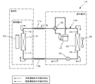
本発明の実施の形態に係る空気調和機10は、図1に示すように、冷凍サイクル回路100に冷媒が還流することにより、空気調和対象の室内Rの空気調和を行う。空気調和機10は、室内機20と室外機30とを有するセパレート型のものである。空気調和機10は、室内機20及び室外機30に加えて、これらを接続するガス連絡配管11a及び液体連絡配管11bを有する。空気調和機10の冷媒には、地球温暖化係数(GWP)が、現在広く空気調和機で使用されているHFC冷媒R410Aよりも小さく、比較的地球温暖化への影響が少ないHFC冷媒であるR32(CH2F2:ジフルオロメタン)のみによって構成される冷媒が用いられる。ただし、これに限られず、R32の含有率が50%を超えるR32リッチ冷媒が用いられてもよい。
As shown in FIG. 1, the
室内機20は、空気調和対象の室内Rに設置され、室内熱交換器21と、室内送風機22とを有する。
The
室内熱交換器21は、冷媒と、空気調和対象の室内Rの空気との熱交換をすることにより、室内Rの空気を冷やしたり、暖めたりする。例えば、冷房運転時においては、室内熱交換器21は、蒸発器として機能して、流入した冷媒を蒸発させる。これにより、室内熱交換器21は、室内熱交換器21の周囲の空気から熱を吸収し、結果として、室内Rの空気を冷却する。また、暖房運転時においては、室内熱交換器21は、凝縮器として機能して、流入した気体冷媒を凝縮させる。これにより、室内熱交換器21は、室内熱交換器21の周囲の空気に熱を放出し、結果として、室内Rの空気を暖化する。
The
室内送風機22は、室内熱交換器21の近傍に設置されている。室内送風機22は、室内熱交換器21を通過する空気流を生成する。そして、生成された空気流によって、熱交換された空気を、空気調和対象の室内Rに供給する。
The
室外機30は、屋外に設置され、圧縮機31と、四方切換弁32と、室外熱交換器33と、膨張弁34と、室外送風機35とを有する。
The
圧縮機31は、供給された冷媒を圧縮する機器である。圧縮機31は、流入した冷媒を、圧縮することにより、高温高圧のガス冷媒に変化させる。そして、圧縮機31は、高温高圧の冷媒を、四方切換弁32に送出する。
The
四方切換弁32は、圧縮機31の下流側に設けられている。四方切換弁32は、冷凍サイクル回路100内の冷媒の還流方向を切り替える。四方切換弁32は、冷凍サイクルを、暖房運転のサイクル及び冷房運転のサイクルのいずれかに切り換える。四方切換弁32は、制御部によって制御されている。
The four-
室外熱交換器33は、流入した冷媒を、蒸発又は凝縮することにより、空気と熱交換をし、空気を冷却又は加熱する。例えば、冷房運転時においては、室外熱交換器33は、凝縮器として機能して、流入した冷媒を凝縮させる。また、暖房運転時においては、室外熱交換器33は、蒸発器として機能して、流入した冷媒を蒸発させる。
The
膨張弁34は、開度が変更可能な減圧装置である。膨張弁34は、例えば、電子制御式膨張弁から構成される。膨張弁34は、流入した冷媒を膨張させることで、高圧の冷媒を低圧に減圧する。そして、膨張弁34は、生成された低圧冷媒を送出する。
The
室外送風機35は、室外熱交換器33の近傍に設置されている。室外送風機35は、室内熱交換器21を通過する空気流を生成する。そして、生成された空気流によって、熱交換された空気を、屋外に排出する。
The
冷凍サイクル回路100は、室内熱交換器21と、圧縮機31と、四方切換弁32と、室外熱交換器33と、膨張弁34と、ガス連絡配管11aと、液体連絡配管11b等とを含んで構成される。
The
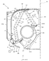
図2は、室内機20の断面図である。室内機20は、図2に示すように、室内熱交換器21及び室内送風機22を収納する室内機筐体23を更に有している。
FIG. 2 is a cross-sectional view of the
室内機筐体23には、空気調和対象の室内Rの空気を吸い込むための吸込口24、25と、室内Rに冷風や温風を供給するための吹出口26とが形成されている。吸込口24は、室内機筐体23の上面(+Z側の面)に形成されている。吸込口25及び吹出口26は、室内機筐体23の前面パネル23aの下方に形成されている。また、吹出口26には、複数枚の左右ベーン27及び複数の上下フラップ28が設けられている。左右ベーン27は、室内送風機22からの空気の左右方向の風向きを規定する。上下フラップ28は、室内送風機22からの空気の上下方向の風向きを規定する。
The
また、室内機筐体23には、凝縮水受け部29A、29Bが形成されている。凝縮水受け部29A、29Bは、冷房運転時等における室内熱交換器21の熱交換により結露した水滴を受ける受皿である。凝縮水受け部29Aと、凝縮水受け部29Bとは、図示しない水路で接続されており、凝縮水受け部29Bが受けた凝縮水は、凝縮水受け部29Aに流れ込む。そして、凝縮水受け部29Aに溜まった凝縮水は、配水管等により、室内Rの外部に排水される。
Further, the
室内送風機22は、送風ファン22aと、送風ファン22aを回転するファンモータとを有している。本実施の形態においては、室内送風機22の送風ファン22aは、クロスフローファンから構成される。室内送風機22の送風ファン22aが回転すると、室内熱交換器21を通過する空気流Aが生成される。そして、生成された空気流Aによって、室内送風機22からの空気は、室内送風機22の下側(−Z側)に形成された風路23bを通り、左右ベーン27及び上下フラップ28に案内されて、吹出口26から吹き出される。なお、本実施の形態においては、室内送風機22の送風ファン22aは、クロスフローファンから構成されているが、これに限られない。送風ファン22aの種類は、室内機20の形態に依存する。例えば、室内機20の形態によって、ターボファンが用いられてもよい。
The
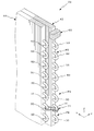
室内熱交換器21は、フィンアンドチューブ型熱交換器から構成され、室内送風機22を覆うように配置されている。室内熱交換器21は、複数のフィンを備える正面側フィンユニット41と、複数のフィンを備える背面側フィンユニット42と、冷媒が流れる複数の伝熱管Tと、シール部材S1〜S3とを有する。また、室内熱交換器21は、図3に示すように、伝熱管T同士を接続するヘアピン部50及びU字配管51を有する。
The
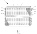
図4は、室内熱交換器及び室内機筐体の斜視図である。なお、図4では、U字配管51は省略されている。正面側フィンユニット41は、図2及び図4に示すように、室内送風機22の正面側(−X側)に配置されている。正面側フィンユニット41は、複数のフィンが、XZ平面に平行、且つ、等間隔に並べて配置されることで構成されている。フィンは、金属から構成され、薄板形状に形成されている。フィン同士の隙間は、室内送風機22によって吸い込まれた空気が通過する流路となる。また、正面側フィンユニット41には、Y軸方向に貫通する複数の貫通孔45が形成されている。
FIG. 4 is a perspective view of the indoor heat exchanger and the indoor unit housing. In FIG. 4, the
背面側フィンユニット42は、室内送風機22の上側(+Z側)、且つ、背面側(+X側)を覆うように配置されている。背面側フィンユニット42は、上側の端部(+Z側の端部)が、正面側フィンユニット41の上側の端部(+Z側の端部)に近接するように、傾斜状に配置されている。背面側フィンユニット42は、正面側フィンユニット41と同様に、複数の金属板状のフィンが、XZ平面に平行、且つ、等間隔に並べて配置されることで構成されている。フィン同士の隙間は、室内送風機22によって吸い込まれた空気が通過する流路となる。背面側フィンユニット42には、Y軸方向に貫通する複数の貫通孔45が形成されている。
The back
伝熱管Tは、Y軸方向を長手方向とするパイプである。伝熱管Tは、金属から構成されている。伝熱管Tは、図2に示すように、正面側フィンユニット41及び背面側フィンユニット42の貫通孔45に挿入されて固定されている。貫通孔45に挿入された伝熱管Tは、フィンに接触した状態で固定される。伝熱管Tは、いずれも同じ形状及び寸法となるように形成されている。伝熱管Tの全長(Y軸方向の長さ)は、例えば、700mmである。
The heat transfer tube T is a pipe whose longitudinal direction is the Y-axis direction. The heat transfer tube T is made of metal. As shown in FIG. 2, the heat transfer tube T is inserted into and fixed to the through
伝熱管Tは、図5に示すように、空気流Aに対して風上となる列と、風下となる列との2列に配置されている。風上の列と風下の列との間隔である列ピッチL1は、例えば、12.7mmである。また、伝熱管Tは、正面側フィンユニット41及び背面側フィンユニット42の上側(+Z側)の端部から、下側(−Z側)の端部まで、等間隔毎(詳しくは、段ピッチL2毎)に配置されている。段ピッチL2は、例えば、20.4mmである。
As shown in FIG. 5, the heat transfer tubes T are arranged in two rows, an upwind row and an leeward row with respect to the air flow A. The row pitch L1 that is the distance between the windward row and the leeward row is, for example, 12.7 mm. In addition, the heat transfer tubes T are arranged at equal intervals from the upper end (+ Z side) to the lower end (−Z side) of the front
室内熱交換器21には、冷媒が流れる経路であるパスP1、P2が形成されている。なお、室内熱交換器21のパスP1、P2の形成数は、任意である。本実施の形態では、2つのパスP1、P2が形成された室内熱交換器21を例に説明する。また、パスP1、P2の端部の伝熱管Tを、入口伝熱管T1及び出口伝熱管T3と呼ぶ。また、入口伝熱管T1と出口伝熱管T3とを接続する複数の伝熱管Tを、中継伝熱管T2と呼ぶ。冷凍サイクルが暖房運転のサイクルである場合には、冷媒は、入口伝熱管T1から流入し、中継伝熱管T2を通って、出口伝熱管T3から流出する。なお、冷凍サイクルが冷房運転のサイクルである場合には、冷凍サイクルを還流する冷媒の流れは逆になるため、冷媒は、出口伝熱管T3から流入し、中継伝熱管T2を通って、入口伝熱管T1から流出する。
The
図5及び図6に示すように、伝熱管T(入口伝熱管T1、中継伝熱管T2、及び出口伝熱管T3)の−Y側の端部同士には、ヘアピン部50が接続されている。ヘアピン部50は、金属から構成される。ヘアピン部50は、略U字形状に形成されている。ヘアピン部50は、正面側フィンユニット41及び背面側フィンユニット42の−Y側の端面から露出した状態で取り付けられている。ヘアピン部50は、例えば、2本の伝熱管Tと一体に形成されている。
As shown in FIGS. 5 and 6, a
図5及び図7に示すように、中継伝熱管T2の+Y側の端部同士には、U字配管51が接続されている。U字配管51は、金属から構成される。U字配管51は、例えば、ロウ付けによって、中継伝熱管T2に接続されている。
As shown in FIG.5 and FIG.7, the
入口伝熱管T1の+Y側の端部には、冷凍サイクルが暖房運転のサイクルである場合に冷媒が流入する入口配管12が接続される。また、出口伝熱管T3には、冷凍サイクルが暖房運転のサイクルである場合に冷媒が流入する出口配管13が接続される。
An
シール部材S1は、図5に示すように、正面側フィンユニット41と背面側フィンユニット42との隙間を塞ぐ部材である。シール部材S1は、正面側フィンユニット41及び背面側フィンユニット42の上側(+Z側)の端部に、Y軸方向に沿って取り付けられている。これにより、空気流Aが、正面側フィンユニット41及び背面側フィンユニット42のフィン同士の間を通過せずに、正面側フィンユニット41と背面側フィンユニット42との隙間を通過することを防止する。シール部材S1の素材は、例えば、樹脂又はゴムである。好ましくは、シール部材S1の素材は、片側を粘着面としたEPDM(エチレンプロピレンジエン)ゴムの発泡体である。本実施の形態に係るシール部材S1に用いられているEPDMゴムの耐熱温度は、およそ100℃である。
As shown in FIG. 5, the seal member S <b> 1 is a member that closes a gap between the front
上述のように構成されたシール部材S1と、パスP1の入口伝熱管T1との間には、複数本の中継伝熱管T2が配置されている。本実施の形態では、シール部材S1と入口伝熱管T1との間には、5本の中継伝熱管T2が配置されている(5本の中継伝熱管T2とは、具体的には、図5に示す中継伝熱管T2−1、T2−2、T2−3、T2−4、T2aである。)。これにより、入口伝熱管T1よりも、中継伝熱管T2が、シール部材S1の近くに配置される。また、説明の便宜上、シール部材S1の最も近くに配置された2つの中継伝熱管T2を、中継伝熱管T2aとする。中継伝熱管T2aは、正面側フィンユニット41の最上端(+Z側の端部)近傍と、背面側フィンユニット42の最上端(+Z側の端部)近傍とに、それぞれ配置されている。
A plurality of relay heat transfer tubes T2 are arranged between the sealing member S1 configured as described above and the inlet heat transfer tube T1 of the path P1. In the present embodiment, five relay heat transfer tubes T2 are arranged between the seal member S1 and the inlet heat transfer tube T1 (specifically, the five relay heat transfer tubes T2 are shown in FIG. 5). Relay heat transfer tubes T2-1, T2-2, T2-3, T2-4, and T2a shown in FIG. Thereby, the relay heat transfer tube T2 is disposed closer to the seal member S1 than the inlet heat transfer tube T1. For convenience of explanation, the two relay heat transfer tubes T2 disposed closest to the seal member S1 are referred to as relay heat transfer tubes T2a. The relay heat transfer tubes T2a are arranged near the uppermost end (+ Z side end) of the
シール部材S2は、正面側フィンユニット41と、室内機筐体23の凝縮水受け部29Aとの隙間を塞ぐ部材である。シール部材S2は、正面側フィンユニット41の下側(−Z側)の端部に、Y軸方向に沿って取り付けられている。これにより、空気流Aが、正面側フィンユニット41のフィン同士の間を通過せずに、正面側フィンユニット41の下側を通過することを防止する。シール部材S2の素材は、例えば、樹脂又はゴムである。好ましくは、シール部材S2の素材は、シール部材S1の素材と同様に、片側を粘着面としたEPDM(エチレンプロピレンジエン)ゴムの発泡体である。本実施の形態に係るシール部材S2に用いられているEPDMゴムの耐熱温度は、およそ100℃である。
The seal member S2 is a member that closes a gap between the front-
上述のように構成されたシール部材S2と入口伝熱管T1との間には、複数本の中継伝熱管T2が配置されている。本実施の形態では、シール部材S2と入口伝熱管T1との間には、3本の中継伝熱管T2が配置されている(3本の中継伝熱管T2とは、具体的には、図5に示す中継伝熱管T2−5、T2−6、T2bである。)。これにより、入口伝熱管T1よりも、中継伝熱管T2が、シール部材S2の近くに配置される。以下、説明の便宜上、シール部材S2の近くに配置された2つの中継伝熱管T2を、中継伝熱管T2bとする。中継伝熱管T2bは、正面側フィンユニット41の最下端(−Z側の端部)近傍に、2つ配置されている。
A plurality of relay heat transfer tubes T2 are arranged between the seal member S2 configured as described above and the inlet heat transfer tube T1. In the present embodiment, three relay heat transfer tubes T2 are arranged between the seal member S2 and the inlet heat transfer tube T1 (specifically, the three relay heat transfer tubes T2 are shown in FIG. 5). Relay heat transfer tubes T2-5, T2-6, and T2b shown in FIG. Thereby, the relay heat transfer tube T2 is disposed closer to the seal member S2 than the inlet heat transfer tube T1. Hereinafter, for convenience of explanation, the two relay heat transfer tubes T2 disposed near the seal member S2 are referred to as relay heat transfer tubes T2b. Two relay heat transfer tubes T2b are arranged in the vicinity of the lowermost end (the end on the −Z side) of the
シール部材S3は、背面側フィンユニット42と、室内機筐体23の凝縮水受け部29Bとの隙間を塞ぐ部材である。シール部材S3は、背面側フィンユニット42の下側(−Z側)の端部に、Y軸方向に沿って取り付けられている。これにより、空気流Aが、背面側フィンユニット42のフィン同士の間を通過せずに、背面側フィンユニット42の下側を通過することを防止する。シール部材S3の素材は、例えば、樹脂又はゴムである。好ましくは、シール部材S3の素材は、シール部材S1、S2と同様に、片側を粘着面としたEPDM(エチレンプロピレンジエン)ゴムの発泡体である。本実施の形態に係るシール部材S3に用いられているEPDMゴムの耐熱温度は、およそ100℃である。
The seal member S3 is a member that closes a gap between the back
上述のように構成されたシール部材S3の近くには、入口伝熱管T1は配置されずに、中継伝熱管T2が配置されている。以下、説明の便宜上、シール部材S3の近くに配置された中継伝熱管T2を、中継伝熱管T2cとする。中継伝熱管T2cは、背面側フィンユニット42の最下端(−Z側の端部)近傍に配置されている。
In the vicinity of the sealing member S3 configured as described above, the relay heat transfer tube T2 is disposed without the inlet heat transfer tube T1. Hereinafter, for convenience of description, the relay heat transfer tube T2 disposed near the seal member S3 is referred to as a relay heat transfer tube T2c. The relay heat transfer tube T <b> 2 c is disposed in the vicinity of the lowermost end (−Z side end portion) of the rear surface
なお、本実施の形態において、シール部材S1〜S3の素材に用いられているEPDMゴムの発泡体は、一般的な室内機20に用いられており、比較的、安価な素材である。
In the present embodiment, the foam of EPDM rubber used for the material of the seal members S1 to S3 is used for the general
仮に、シール部材S1〜S3がなく、上記隙間が存在した場合、冷房運転時に室内熱交換器21を介して熱交換された温度及び湿度が低い空気と、隙間を通過して熱交換されなかった空気とが、図2に示すように、室内機20の風路23b等で混ざり合う。そして、熱交換されなかった空気の水分が露点以下に冷やされて凝縮し、風路23b内の構成部品(例えば、室内送風機22など)に露となって付着し、吹出口26から外に飛び出し、室内機20周辺の家具や電化製品を損傷するおそれがある。このため、シール部材S1〜S3は、必要不可欠な部材である。
If there is no seal member S1 to S3 and the gap is present, the heat exchanged through the
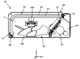
図8は、室外機30の断面図である。室外機30は、図8に示すように、圧縮機31、室外熱交換器33、及び室外送風機35等に加えて、上記各装置を収納する室外機筐体36を有している。
FIG. 8 is a cross-sectional view of the
室外機筐体36は、略直方体形状に形成されている。室外機筐体36は、内部を2つの空間に仕切る仕切板37を有している。仕切板37は、室外機筐体36の底面から、鉛直方向(+Z方向)に延出するように形成されている。この仕切板37によって、室外機筐体36の内部は、圧縮機31等が収容される機械室Mと、室外送風機35等が収容される送風室Fとに区画される。機械室Mは、室外機筐体36の内部空間の+Y側に形成され、送風室Fは、室外機筐体36の内部空間の−Y側に形成されている。仕切板37は、風雨等による雨水が、送風室Fを介して、機械室Mに浸入することを防止するためのものである。
The
室外送風機35は、室外熱交換器33の近傍に設置され、送風ファン35aと、送風ファン35aを回転するファンモータ35bとを有している。室外送風機35は、送風ファン35aの回転により、室外熱交換器33を通過する空気流を生成する。そして、生成された空気流によって、熱交換された空気を、屋外に排出する。本実施の形態においては、送風ファン35aには、背面や側方から空気を吸引するプロペラファンが用いられている。また、室外送風機35は、1つ又は2つの送風ファン35aを有している。
The
室外熱交換器33は、室内熱交換器21と同様に、フィンアンドチューブ型熱交換器から構成されている。室外熱交換器33は、室外送風機35の側面側(−Y側)及び背面側(+X側)を覆うように配置されている。室外熱交換器33は、複数のフィンを備える正面側フィンユニット43と、複数のフィンを備える背面側フィンユニット44と、緩衝部材60と、バンド部材71、72とを有する。また、室外熱交換器33は、図9に示すように、冷媒が流れる複数の伝熱管T、ヘアピン部50、及びU字配管51を有する。
The
図10は、室外熱交換器33及び室外機筐体36の斜視図である。なお、図10では、ヘアピン部50及びU字配管51は省略されている。正面側フィンユニット43は、図10に示すように、複数のフィンを有する。フィンは、金属から構成され、薄板形状に形成されている。正面側フィンユニット43は、フィンが等間隔に並べて配置されることで構成されている。正面側フィンユニット43は、XY断面視で、略L字形状に形成される。また、正面側フィンユニット43には、複数の貫通孔が形成されている。
FIG. 10 is a perspective view of the
背面側フィンユニット44は、正面側フィンユニット43に重ねて配置されている。背面側フィンユニット44は、複数のフィンを有する。フィンは、金属から構成され、薄板形状に形成されている。背面側フィンユニット44は、フィンが等間隔に並べて配置されることで構成されている。背面側フィンユニット44は、XY断面視で、略L字形状に形成される。また、背面側フィンユニット44には、複数の貫通孔が形成されている。
The rear
伝熱管Tは、図9に示すように、金属から構成されるパイプである。伝熱管Tは、図10を参照するとわかるように、正面側フィンユニット43及び背面側フィンユニット44の貫通孔に挿入されて固定されている。伝熱管Tは、いずれも同じ内外径及び全長となるように形成されている。伝熱管Tの全長は、例えば、700mmである。
また、伝熱管Tは、図11に示すように、空気流Aに対して風上となる列と、風下となる列との2列に配置されている。風上の列と風下の列との間隔である列ピッチL1は、例えば、12.7mmである。また、伝熱管Tは、正面側フィンユニット43及び背面側フィンユニット44の上側(+Z側)の端部から、下側(−Z側)の端部まで、Z軸方向に沿って、等間隔毎(詳しくは、段ピッチL2毎)に配置されている。段ピッチL2は、例えば、20.4mmである。
As shown in FIG. 9, the heat transfer tube T is a pipe made of metal. As can be seen with reference to FIG. 10, the heat transfer tube T is inserted into and fixed to the through holes of the front
In addition, as shown in FIG. 11, the heat transfer tubes T are arranged in two rows, an upwind row and an upwind row with respect to the air flow A. The row pitch L1 that is the distance between the windward row and the leeward row is, for example, 12.7 mm. The heat transfer tubes T are equally spaced along the Z-axis direction from the upper (+ Z side) end of the
室外熱交換器33には、冷媒が流れる経路であるパスP3〜P6が形成されている。なお、室外熱交換器33のパスP3〜P6の形成数は、任意である。本実施の形態では、4つのパスP3〜P6が形成された室外熱交換器33を例に説明する。以下、パスP3〜P6の端部の伝熱管Tを、入口伝熱管T1及び出口伝熱管T3とする。また、入口伝熱管T1と出口伝熱管T3とを接続する複数の伝熱管Tを、中継伝熱管T2とする。冷凍サイクルが冷房運転のサイクルである場合には、冷媒は、入口伝熱管T1から流入し、中継伝熱管T2を通って、出口伝熱管T3から流出する。なお、冷凍サイクルが暖房運転のサイクルである場合には、冷凍サイクルを還流する冷媒の流れは逆になるため、冷媒は、出口伝熱管T3から流入し、中継伝熱管T2を通って、入口伝熱管T1から流出する。
In the
図11及び図12に示すように、伝熱管T(入口伝熱管T1、中継伝熱管T2、及び出口伝熱管T3)の−X側の端部同士には、略U字形状に形成されたヘアピン部50が接続されている。ヘアピン部50は、正面側フィンユニット43及び背面側フィンユニット44の−X側の端面から露出した状態で配置されている。ヘアピン部50は、例えば、2本の伝熱管Tと一体に形成されている。
As shown in FIG.11 and FIG.12, the hairpin formed in the substantially U shape at the edge parts of -X side of the heat exchanger tube T (inlet heat exchanger tube T1, relay heat exchanger tube T2, and outlet heat exchanger tube T3). The
図13及び図14に示すように、中継伝熱管T2の+Y側の端部同士には、U字配管51が接続されている。U字配管51は、例えば、ロウ付けによって、伝熱管Tに接続されている。
As shown in FIGS. 13 and 14,
入口伝熱管T1の+Y側の端部には、冷凍サイクルが冷房運転のサイクルである場合に冷媒が流入する入口配管14が接続される。また、出口伝熱管T3には、冷凍サイクルが冷房運転のサイクルである場合に冷媒が流出する出口配管15が接続される。
An
緩衝部材60は、図8及び図10に示すように、室外機筐体36の内壁面と、室外熱交換器33との間に配置されている。これにより、緩衝部材60は、室外機30の搬送時等において、室外機筐体36に対する室外熱交換器33の干渉を防いだり、製品輸送時の落下による損傷を防いだりする。本実施の形態においては、室外熱交換器33の正面側フィンユニット43の−X側の端面の上側近傍に配置されている。緩衝部材60の素材は、例えば、発泡スチロール材である。本実施の形態に係る緩衝部材60に用いられている発泡スチロール材の耐熱温度は、およそ80℃である。
As shown in FIGS. 8 and 10, the
なお、本実施の形態において、緩衝部材60に用いられている発泡スチロール材は、一般的な室外機30に用いられているものであり、比較的、市場流通性が高く、安価なものである。
In the present embodiment, the foamed polystyrene material used for the
上述のように構成された緩衝部材60と、パスP3の入口伝熱管T1との間には、図11に示すように、複数本の中継伝熱管T2が配置されている。本実施の形態では、緩衝部材60と入口伝熱管T1との間には、5本の中継伝熱管T2が配置されている(5本の中継伝熱管T2とは、具体的には、図11に示す中継伝熱管T2−7、T2−8、T2−9、T2−10、T2dである。)。これにより、パスP3の入口伝熱管T1よりも、パスP3の中継伝熱管T2が、緩衝部材60の近くに配置される。以下、説明の便宜上、緩衝部材60の近くに配置された中継伝熱管T2を、中継伝熱管T2dとする。中継伝熱管T2dは、緩衝部材60の下側(−Z側)に配置されている。
As shown in FIG. 11, a plurality of relay heat transfer tubes T2 are disposed between the
バンド部材71は、図11及び図12に示すように、正面側フィンユニット43と背面側フィンユニット44とを相互に固定する。バンド部材71は、パスP5のヘアピン部50とヘアピン部50とを結ぶ紐状の部材である。バンド部材71の素材は、例えば、ナイロンである。好ましくは、6,6−ナイロンである。本実施の形態に係るバンド部材71に用いられている6,6−ナイロンの耐熱温度は、およそ85℃である。
As shown in FIGS. 11 and 12, the
上述のように構成されたバンド部材71と、パスP5の入口伝熱管T1との間には、図11に示すように、4本の中継伝熱管T2が配置されている(4本の中継伝熱管T2とは、具体的には、図11に示す中継伝熱管T2−11、T2−12、T2f、T2eである。)。これにより、パスP5の入口伝熱管T1よりも、パスP5の中継伝熱管T2が、バンド部材71の近くに配置される。以下、説明の便宜上、バンド部材71の近くに配置された中継伝熱管T2を、中継伝熱管T2eとする。
As shown in FIG. 11, four relay heat transfer tubes T2 are arranged between the
バンド部材72は、バンド部材71と同様に、図13に示すように、正面側フィンユニット43と背面側フィンユニット44とを固定するために用いられる。バンド部材72は、パスP5のU字配管51とU字配管51とを結ぶ紐状の部材である。バンド部材72の素材は、例えば、ナイロンである。好ましくは、バンド部材71と同様に、6,6−ナイロンである。本実施の形態に係るバンド部材72に用いられている6,6−ナイロンの耐熱温度は、およそ85℃である。
Similarly to the
上述のように構成されたバンド部材72と、パスP5の入口伝熱管T1との間には、3本の中継伝熱管T2が配置されている(3本の中継伝熱管T2とは、具体的には、図13に示す中継伝熱管T2−11、T2−12、T2fである。)。これにより、パスP5の入口伝熱管T1よりも、パスP5の中継伝熱管T2が、バンド部材72の近くに配置されている。なお、説明の便宜上、バンド部材72の近くに配置されている中継伝熱管T2を、中継伝熱管T2fとする。
Three relay heat transfer tubes T2 are arranged between the
なお、バンド部材71、72に用いられている6,6−ナイロンは、一般的な室外熱交換器33に用いられているものであり、比較的、市場流通性が高く、安価なものである。
Note that 6,6-nylon used for the
以上のように構成された空気調和機10は、冷房運転及び暖房運転を行うことにより、空気調和対象の室内Rの空気調和を行う。以下、空気調和機10の冷凍サイクルの動作について、図1を用いて説明する。図1における実線の矢印は、冷房運転時における冷媒の流れを示している。また、図1における点線の矢印は、暖房運転時における冷媒の流れを示している。
The
冷房運転の場合、四方切換弁32は、圧縮機31からの冷媒を、室外熱交換器33に送出するように切り替えられる。すると、冷媒は、図1における実線の矢印に示されるように、流れるようになる。この場合、室外熱交換器33は、凝縮器として機能し、室内熱交換器21は、蒸発器として機能する。
In the cooling operation, the four-
先ず、圧縮機31に冷媒が流入すると、流入した冷媒は、圧縮機31によって圧縮される。すると、冷媒は、圧力及び比エンタルピが上昇し、高温高圧のガス冷媒に変化し、圧縮機31から送出される。圧縮機31から送出されたガス冷媒は、四方切換弁32を通過して、室外熱交換器33に流入する。詳しくは、冷媒は、分流管を介することによって、図11及び図13に示すように、室外熱交換器33のパスP3〜P6に流入する。
First, when the refrigerant flows into the
ここで、本実施の形態では、冷媒としてR32が用いられている。このため、例えば、冷媒としてR22等が用いられた場合に比べて、冷媒の温度がより高くなる。結果として、室外熱交換器33の入口配管14の表面温度は、冷媒としてR22等が用いられた場合の入口配管の温度よりも、20℃程度高くなる。具体的には、冷媒としてR32が用いられた場合、入口配管14の表面温度は、約110℃になる。
Here, in the present embodiment, R32 is used as the refrigerant. For this reason, the temperature of a refrigerant | coolant becomes higher compared with the case where R22 etc. are used as a refrigerant | coolant, for example. As a result, the surface temperature of the
図15は、凝縮器(暖房運転時の室内熱交換器21、冷房運転時の室外熱交換器33)に流入したR32冷媒が通過する伝熱管Tの本数と、伝熱管Tの表面温度との関係を示したグラフである。図15の横軸の伝熱管Tの本数とは、凝縮器に流入した冷媒が通過する1本目の伝熱管T(入口伝熱管T1)を「1」として、以降、2本目の伝熱管Tを「2」、3本目の伝熱管Tを「3」、4本目の伝熱管Tを「4」としていくことで示される値である。なお、図15に示されるグラフは、全長700mmの伝熱管Tを用いるとともに、伝熱管T同士の列ピッチL1を12.7mm、段ピッチL2を20.4mmとした場合のものである。図15を参照するとわかるように、1本目の伝熱管T(入口伝熱管T1)の温度は、約110℃である。そして、2本目以降の伝熱管T(中継伝熱管T2)の温度は低下していく。具体的には、2本目の伝熱管T(中継伝熱管T2)の温度は、約92℃に下がり、3本目の伝熱管T(中継伝熱管T2)の温度は、約75℃にまで下がる。そして、4本目以降の伝熱管T(中継伝熱管T2)は、約70℃で一定となる。なお、列ピッチL1及び段ピッチL2は、伝熱管Tの全長に比べて十分に小さいため、列ピッチL1及び段ピッチL2の寸法に若干の変更があった場合においても、図15のグラフの結果と、同等の結果が得られる。
FIG. 15 shows the number of heat transfer tubes T through which the R32 refrigerant flowing into the condenser (the
図11に示すように、緩衝部材60と、パスP3の入口伝熱管T1との間には、5本の中継伝熱管T2が配置されている。このため、緩衝部材60に最も近い中継伝熱管T2dは、冷媒が6本目に流れる伝熱管Tに相当する。図15を参照すると、中継伝熱管T2dの温度は、約70℃になることが分かる。また、バンド部材71と、パスP5の入口伝熱管T1との間には、4本の中継伝熱管T2が配置されている。このため、バンド部材71に最も近い中継伝熱管T2eは、冷媒が5本目に流れる伝熱管Tに相当する。したがって、図15を参照すると、中継伝熱管T2eの温度は、約70℃になることが分かる。
As shown in FIG. 11, five relay heat transfer tubes T2 are arranged between the
図13に示すように、バンド部材71と、パスP5の入口伝熱管T1との間には、3本の中継伝熱管T2が配置されている。このため、バンド部材72に近い中継伝熱管T2fは、冷媒が4本目に流れる伝熱管Tに相当する。図15を参照すると、中継伝熱管T2fの温度は、約70℃になることが分かる。
As shown in FIG. 13, three relay heat transfer tubes T2 are arranged between the
図1に戻り、室外熱交換器33に、ガス冷媒が流入すると、冷媒は、室外送風機35によって供給される外部空気(外気)との熱交換によって凝縮する。すると、冷媒は、圧力一定のまま、比エンタルピが下降する。これにより、ガス冷媒は、低温高圧の液冷媒に変化する。そして、液冷媒は、室外熱交換器33から送出される。
Returning to FIG. 1, when the gas refrigerant flows into the
膨張弁34に、液冷媒が流入すると、液冷媒は、膨張弁34によって膨張する。すると、液冷媒は、比エンタルピ一定のまま、減圧されて、低圧の状態に変化する。そして、この液冷媒は、膨張弁34から送出される。
When the liquid refrigerant flows into the
膨張弁34から送出された液冷媒は、液体連絡配管11bを通過して、室内機20の冷媒流路に流入する。そして、室内熱交換器21に流入する。詳しくは、冷媒は、分流管を介することによって、図5に示すように、室内熱交換器21のパスP1、P2に流入する。
The liquid refrigerant sent out from the
図1に戻り、室内熱交換器21に、液冷媒が流入すると、冷媒は、室内送風機22によって供給される空気調和対象の室内Rの空気との熱交換によって蒸発する。すると、圧力一定のまま、冷媒の比エンタルピが上昇する。これにより、冷媒は、高温低圧の加熱状態のガス冷媒に変化する。また、上記熱交換によって、室内Rの空気は冷却される。この結果、空気調和対象の室内Rの室温は低下する。
Returning to FIG. 1, when the liquid refrigerant flows into the
室内熱交換器21から送出された加熱状態のガス冷媒は、ガス連絡配管11aを通過して、室外機30の冷媒流路に流入する。そして、室外機30の四方切換弁32を介して、再び、圧縮機31に流入する。以下、上述の冷凍サイクルを繰り返す。なお、除湿運転の冷凍サイクルは、上述の冷房運転の冷凍サイクルと同様である。
The heated gas refrigerant sent out from the
次に、暖房運転の場合、四方切換弁32は、圧縮機31からの冷媒を、室内熱交換器21に送出するように切り替えられる。すると、冷媒は、図1における点線の矢印に示されるように、流れるようになる。この場合、室外熱交換器33は、蒸発器として機能するとともに、室内熱交換器21は、凝縮器として機能する。
Next, in the heating operation, the four-
圧縮機31から送出されたガス冷媒は、四方切換弁32を通過して、室外機30から流出する。そして、ガス連絡配管11aを通過して、室内機20の冷媒流路に流入する。そして、入口配管12を経由して、室内熱交換器21に流入する。詳しくは、冷媒は、分流管を介することによって、図5に示すように、室内熱交換器21のパスP1、P2に流入する。
The gas refrigerant sent out from the
ここで、本実施の形態では、冷媒としてR32が用いられているため、図15を参照するとわかるように、室内熱交換器21の入口伝熱管T1の温度は、約110℃になる。
Here, in the present embodiment, since R32 is used as the refrigerant, the temperature of the inlet heat transfer tube T1 of the
図5に示すように、シール部材S1の近くに配置された中継伝熱管T2aは、入口伝熱管T1を1本目とすると、12本目、13本目に冷媒が流れる伝熱管Tに相当する。したがって、図15を参照すると、中継伝熱管T2aの表面温度は、いずれも約70℃になることが分かる。また、シール部材S2に近くに配置された中継伝熱管T2bは、4本目、5本目の伝熱管Tに相当する。したがって、図15を参照すると、中継伝熱管T2bの表面温度は、いずれも約70℃になることが分かる。また、シール部材S3に近くに配置された中継伝熱管T2cは、8本目の伝熱管Tに相当する。したがって、図15を参照すると、中継伝熱管T2cの温度は、約70℃になることが分かる。 As shown in FIG. 5, the relay heat transfer tube T2a disposed near the seal member S1 corresponds to the heat transfer tube T through which the refrigerant flows in the 12th and 13th tubes, assuming that the inlet heat transfer tube T1 is the first one. Therefore, referring to FIG. 15, it can be seen that the surface temperature of the relay heat transfer tube T2a is about 70 ° C. Further, the relay heat transfer tube T2b disposed near the seal member S2 corresponds to the fourth and fifth heat transfer tubes T. Therefore, referring to FIG. 15, it can be seen that the surface temperature of the relay heat transfer tube T2b is about 70 ° C. The relay heat transfer tube T2c disposed near the seal member S3 corresponds to the eighth heat transfer tube T. Therefore, referring to FIG. 15, it can be seen that the temperature of the relay heat transfer tube T2c is about 70.degree.
図1に戻り、室内熱交換器21に、ガス冷媒が流入すると、冷媒は、室内送風機22によって供給される空気調和対象の室内Rの空気との熱交換によって凝縮する。すると、冷媒は、圧力一定のまま、比エンタルピが下降する。これにより、ガス冷媒は、低温高圧の過冷却状態の液冷媒に変化する。また、上記熱交換によって、室内Rの空気は暖められる。この結果、空気調和対象の室内Rの室温は上昇する。
Returning to FIG. 1, when the gas refrigerant flows into the
室内熱交換器21から送出された過冷却状態の液冷媒は、液体連絡配管11bを通過して、室外機30の冷媒流路に流入する。そして、室外機30の膨張弁34に流入する。
The supercooled liquid refrigerant sent out from the
膨張弁34に、液冷媒が流入すると、液冷媒は、膨張弁34によって膨張する。すると、液冷媒は、比エンタルピ一定のまま、減圧されて、低温低圧の状態に変化する。このとき、冷媒は、ガス冷媒となる。そして、このガス冷媒は、膨張弁34から送出される。そして、室外機30の室外熱交換器33に流入する。
When the liquid refrigerant flows into the
室外熱交換器33に、ガス冷媒が流入すると、ガス冷媒は、室外送風機35によって供給される外部空気(外気)との熱交換によって凝縮する。すると、冷媒は、圧力一定のまま、比エンタルピが上昇する。これにより、ガス冷媒は、高温低圧の加熱状態のガス冷媒に変化する。そして、このガス冷媒は、室外熱交換器33から送出される。
When the gas refrigerant flows into the
室外熱交換器33から送出された加熱状態のガス冷媒は、四方切換弁32を介して、再び、圧縮機31に流入する。以下、上述の冷凍サイクルを繰り返す。
The heated gas refrigerant sent from the
以上、説明したように、本実施の形態に係る室内熱交換器21では、図5に示すように、入口配管12が、シール部材S1〜S3の近くに配置された中継伝熱管T2a、T2b、T2cではなく、中継伝熱管T2a、T2b、T2cよりも遠くに配置された入口伝熱管T1に接続されている。これにより、暖房運転時に、入口配管12の高熱が、シール部材S1〜S3に伝わりにくくなり、シール部材S1〜S3のシール能力の低下を抑制することができる。
As described above, in the
例えば、入口配管12が、シール部材S1〜S3の近くに配置された中継伝熱管T2a、T2b、T2cに接続されていると、入口配管12の高熱が、中継伝熱管T2a、T2b、T2cを介して、シール部材S1〜S3に伝わりやすくなる。この結果、シール部材S1〜S3が、高温になりやすくなる。特に、本実施の形態では、冷媒としてR32が用いられているため、入口配管12の高熱が伝わり、1本目に冷媒が流れる伝熱管Tの表面温度が約110℃に達する(図15参照。)。これにより、1本目に冷媒が流れる伝熱管Tの高熱が、シール部材S1〜S3に伝わり、シール部材S1〜S3の温度が、耐熱温度である100℃を超えるおそれが生ずる。結果として、シール部材S1〜S3のシール能力の低下が起こり、シール部材S1〜S3の信頼性が低下するおそれが生ずる。
For example, when the
しかしながら、本実施の形態では、冷媒の入口配管12は、シール部材S1〜S3の近くに配置された中継伝熱管T2a、T2b、T2cではなく、中継伝熱管T2a、T2b、T2cよりも遠くに配置された入口伝熱管T1に接続されている。これにより、入口配管12の高熱が、シール部材S1〜S3に伝わりにくくなり、シール部材S1〜S3のシール能力の低下を抑制することができる。
However, in the present embodiment, the
また、本実施の形態では、暖房運転時における冷媒の入口配管12の表面温度の高温化を防止するために、冷凍サイクル回路100を還流する冷媒量を、本来の適正な冷媒量よりも少なくしたり、膨張弁34の開度を開けることで、膨張弁34のCv値を大きくしたりする必要がない。このため、空気調和機10の暖房運転能力及び運転効率の低下を防止することができる。
Further, in the present embodiment, in order to prevent the surface temperature of the
また、本実施の形態では、シール部材S1〜S3に、耐熱性の高い高価な素材を用いる必要もない。結果として、製品の高コスト化を抑制できる。また、本実施の形態に係るシール部材S1〜S3は、冷媒としてR32が用いられた場合でも、R22、R410A、R407C等を用いた場合と同等のシール能力を発揮することができる。 Moreover, in this Embodiment, it is not necessary to use an expensive raw material with high heat resistance for seal member S1-S3. As a result, cost increase of the product can be suppressed. Moreover, even when R32 is used as the refrigerant, the sealing members S1 to S3 according to the present embodiment can exhibit the same sealing ability as when R22, R410A, R407C, or the like is used.
また、本実施の形態に係る室外熱交換器33では、図11に示すように、入口配管14が、緩衝部材60の近くに配置された中継伝熱管T2dではなく、中継伝熱管T2dよりも遠くに配置された入口伝熱管T1に接続されている。これにより、冷房運転時に、入口配管14の高熱が、緩衝部材60に伝わりにくくなり、緩衝部材60の衝撃緩和能力の低下を抑制することができる。
In addition, in the
例えば、入口配管14が、緩衝部材60の近くに配置された中継伝熱管T2dに接続されていると、入口配管14の高熱が、中継伝熱管T2dを介して、緩衝部材60に伝わりやすくなる。この結果、緩衝部材60が高温になりやすくなる。特に、本実施の形態では、冷媒としてR32が用いられているため、入口配管14の高熱が伝わり、1本目に冷媒が流れる伝熱管Tの表面温度が約110℃に達する(図15参照。)。このため、1本目に冷媒が流れる伝熱管Tの高熱が、緩衝部材60に伝わり、緩衝部材60の温度が、耐熱温度である80℃を超えるおそれが生ずる。結果として、緩衝部材60が劣化しやすくなり、衝撃緩和能力の低下が起こる。
For example, when the
しかしながら、本実施の形態では、冷媒の入口配管14は、緩衝部材60の近くに配置された中継伝熱管T2dではなく、中継伝熱管T2dよりも遠くに配置された入口伝熱管T1に接続されている。これにより、入口配管14の高熱が、緩衝部材60に伝わりにくくなり、緩衝部材60の劣化を抑制することができる。
However, in the present embodiment, the
また、本実施の形態では、図11及び図13に示すように、入口配管14が、バンド部材71、72の近くに配置された中継伝熱管T2e、T2fではなく、中継伝熱管T2e、T2fよりも遠くに配置された入口伝熱管T1に接続されている。これにより、冷房運転時に、入口配管14の高熱が、バンド部材71、72に伝わりにくくなり、バンド部材71、72の劣化を抑制することができる。
Moreover, in this Embodiment, as shown in FIG.11 and FIG.13, the inlet piping 14 is not the relay heat exchanger tube T2e and T2f arrange | positioned near the
例えば、入口配管14が、バンド部材71、72の近くに配置された中継伝熱管T2e、T2fに接続されていると、入口配管14の高熱が、中継伝熱管T2e、T2fを介して、バンド部材71、72に伝わりやすくなる。この結果、バンド部材71、72が、高温になりやすくなる。特に、本実施の形態では、冷媒としてR32が用いられているため、入口配管14の高熱が伝わり、1本目に冷媒が流れる伝熱管Tの表面温度が約110℃に達する(図15参照。)。これにより、1本目に冷媒が流れる伝熱管Tの高熱がバンド部材71、72に伝わり、バンド部材71、72の温度が、耐熱温度である85℃を超えるおそれが生ずる。結果として、バンド部材71、72が劣化しやすくなる。
For example, when the
しかしながら、本実施の形態では、冷媒の入口配管14は、バンド部材71、72の近くに配置された中継伝熱管T2e、T2fではなく、中継伝熱管T2e、T2fよりも遠くに配置された入口伝熱管T1に接続されている。これにより、入口配管14の高熱が、バンド部材71、72に伝わりにくくなり、バンド部材71、72の劣化を抑制することができる。
However, in the present embodiment, the
また、本実施の形態では、冷房運転時における冷媒の入口配管14の表面温度の高温化を防止するために、冷凍サイクル回路100を還流する冷媒量を、本来の適正な冷媒量よりも少なくしたり、膨張弁34の開度を開けることで、膨張弁34のCv値を大きくしたりする必要がない。このため、空気調和機10の暖房運転能力及び運転効率の低下を防止することができる。
Further, in the present embodiment, in order to prevent the surface temperature of the
また、緩衝部材60、バンド部材71、72に、耐熱性の高い高価な素材を用いる必要もない。結果として、製品の高コスト化を抑制できる。また、本実施の形態に係る緩衝部材60、バンド部材71、72は、冷媒としてR32が用いられた場合でも、R22、R410A、R407C等を用いた場合と同等の性能を発揮することができる。
Further, it is not necessary to use an expensive material having high heat resistance for the
以上、本発明の実施の形態について説明したが、本発明は上記実施の形態によって限定されるものではない。 As mentioned above, although embodiment of this invention was described, this invention is not limited by the said embodiment.
例えば、本実施の形態では、図5に示すように、シール部材S1と入口伝熱管T1との間に、シール部材S1の最も近くに配置された中継伝熱管T2aを含めて、5本の中継伝熱管T2が配置されている。しかしながら、これに限られない。シール部材S1と入口伝熱管T1との間には、少なくとも1本の中継伝熱管T2が配置されていればよい。換言すると、シール部材S1に最も近い伝熱管Tが、100℃以上にならないように、シール部材S1に最も近い伝熱管Tに、暖房運転時における冷媒の入口配管12が接続されていなければよい。これは、図15に示したように、冷媒がR32の場合、2本目の伝熱管Tの表面温度が、100℃より小さい約92℃まで低下するからである。
For example, in the present embodiment, as shown in FIG. 5, five relays including the relay heat transfer tube T2a disposed closest to the seal member S1 between the seal member S1 and the inlet heat transfer tube T1. A heat transfer tube T2 is disposed. However, it is not limited to this. It is sufficient that at least one relay heat transfer tube T2 is arranged between the seal member S1 and the inlet heat transfer tube T1. In other words, the
また、本実施の形態では、図5に示すように、シール部材S2と入口伝熱管T1との間に、シール部材S2の最も近くに配置された中継伝熱管T2bを含めて、複数本の中継伝熱管T2が配置されている。しかしながら、これに限られない。シール部材S2と入口伝熱管T1との間には、少なくとも1本の中継伝熱管T2が配置されていればよい。換言すると、シール部材S2に最も近い伝熱管Tが、100℃以上にならないように、シール部材S2に最も近い伝熱管Tに、暖房運転時における冷媒の入口配管12が接続されていなければよい。これは、図15に示したように、冷媒がR32の場合、2本目の伝熱管Tの表面温度が、100℃より小さい約92℃まで低下するからである。
Further, in the present embodiment, as shown in FIG. 5, a plurality of relays including a relay heat transfer tube T2b disposed closest to the seal member S2 between the seal member S2 and the inlet heat transfer tube T1. A heat transfer tube T2 is disposed. However, it is not limited to this. It is sufficient that at least one relay heat transfer tube T2 is disposed between the seal member S2 and the inlet heat transfer tube T1. In other words, the
同様に、シール部材S3に最も近い伝熱管Tに、暖房運転時における冷媒の入口配管12が接続されていなければ、これ以外の伝熱管Tの配置は任意である。すなわち、シール部材S3に最も近い伝熱管Tが、100℃以上にならないように、入口配管12が伝熱管Tに接続されていればよい。
Similarly, as long as the
また、本実施の形態では、図11に示すように、緩衝部材60と、パスP3の入口伝熱管T1との間に、緩衝部材60の最も近くに配置された中継伝熱管T2dを含めて、5本の中継伝熱管T2が配置されている。しかしながら、これに限らず、緩衝部材60と入口伝熱管T1との間に、4本以下の中継伝熱管T2が配置されていてもよいし、6本以上の中継伝熱管T2が配置されていてもよい。ただし、緩衝部材60の耐熱温度は、80℃であること、図15に示したように、2本目の伝熱管Tの表面温度が約92℃であり、3本目の伝熱管の表面温度が約75℃であること、を考慮すると、図11に示す中継伝熱管T2dは、冷媒が1本目及び2本目に通過する伝熱管Tにしないことが望ましい。すなわち、緩衝部材60の最も近くに配置された中継伝熱管T2dは、入口伝熱管T1を1本目に冷媒が通過する伝熱管Tとした場合、3本目以降に冷媒が通過する伝熱管Tにすることが望ましい。
In the present embodiment, as shown in FIG. 11, the relay heat transfer tube T2d disposed closest to the
また、本実施の形態では、図11に示すように、バンド部材71と、パスP5の入口伝熱管T1との間に、バンド部材71の最も近くに配置された中継伝熱管T2eを含めて、4本の中継伝熱管T2が配置されている。しかしながら、これに限らず、バンド部材71と入口伝熱管T1との間に、3本以下の中継伝熱管T2が配置されていてもよいし、5本以上の中継伝熱管T2が配置されていてもよい。ただし、バンド部材71の耐熱温度は、85℃であること、図15に示したように、2本目の伝熱管Tの表面温度が約92℃であり、3本目の伝熱管の表面温度が約75℃であること、を考慮すると、図11に示す中継伝熱管T2eは、1本目及び2本目の伝熱管Tにしないことが望ましい。すなわち、バンド部材71の最も近くに配置された中継伝熱管T2eは、入口伝熱管T1を1本目に冷媒が通過する伝熱管Tとした場合、3本目以降に冷媒が通過する伝熱管Tにすることが望ましい。
Further, in the present embodiment, as shown in FIG. 11, the relay heat transfer tube T2e disposed closest to the
また、本実施の形態では、図13に示すように、バンド部材72と、パスP5の入口伝熱管T1との間に、バンド部材72の最も近くに配置された中継伝熱管T2fを含めて、3本の中継伝熱管T2が配置されている。しかしながら、これに限らず、バンド部材72と入口伝熱管T1との間に、2本以下の中継伝熱管T2が配置されていてもよいし、4本以上の中継伝熱管T2が配置されていてもよい。ただし、バンド部材72の耐熱温度は、85℃であること、図15に示したように、2本目の伝熱管Tの表面温度が約92℃であり、3本目の伝熱管の表面温度が約75℃であること、を考慮すると、図13に示す中継伝熱管T2fは、1本目及び2本目の伝熱管Tにしないことが望ましい。すなわち、バンド部材72の最も近くに配置された中継伝熱管T2fは、入口伝熱管T1を1本目に冷媒が通過する伝熱管Tとした場合、3本目以降に冷媒が通過する伝熱管Tにすることが望ましい。
In the present embodiment, as shown in FIG. 13, the relay heat transfer tube T2f disposed closest to the
また、本実施の形態に係る室内熱交換器21は、2つのフィンユニット(正面側フィンユニット41、背面側フィンユニット42)を有している。しかしながら、これに限らず、3つ以上のフィンユニットを有していてもよい。同様に、本実施の形態に係る室外熱交換器33は、2つのフィンユニット(正面側フィンユニット43、背面側フィンユニット44)を有している。しかしながら、これに限らず、3つ以上のフィンユニットを有していてもよい。
The
また、本実施の形態に係る室内熱交換器21には、2つのパスP1、P2が形成されている。しかしながら、これに限られない。例えば、室内熱交換器21に形成されるパスは1つでもよいし、3つ以上でもよい。
In addition, two passes P1 and P2 are formed in the
また、本実施の形態に係る室外熱交換器33には、4つのパスP3〜P6が形成されている。しかしながら、これに限られない。例えば、室外熱交換器33に形成されるパスは、3つ以下でもよいし、5つ以上でもよい。
In addition, four paths P3 to P6 are formed in the
また、本実施の形態では、シール部材S1〜S3の素材は、片側を粘着面としたEPDMゴムの発泡体であるが、これに限られず、別の素材であってもよい。ただし、コスト及び入手性等の観点から、EPDMゴムの発泡体であることが好ましい。 Moreover, in this Embodiment, although the raw material of sealing member S1-S3 is a foam of EPDM rubber which made the one side the adhesion surface, it is not restricted to this, Another raw material may be sufficient. However, from the viewpoints of cost, availability, etc., an EPDM rubber foam is preferable.
また、本実施の形態では、緩衝部材60の素材は、発泡スチロール材であるが、これに限られず、別の素材であってもよい。ただし、コスト及び入手性等の観点から、発泡スチロール材であることが好ましい。
Moreover, in this Embodiment, although the raw material of the
また、本実施の形態では、バンド部材71、72の素材は、6,6−ナイロンであるが、これに限られず、別の素材であってもよい。ただし、コスト及び入手性等の観点から、6,6−ナイロンであることが好ましい。
Moreover, in this Embodiment, although the raw material of the
また、本実施の形態では、室外熱交換器33は、図10及び図11に示すように、1つの緩衝部材60を有している。しかしながら、これに限られない。室外熱交換器33は、2つ以上の緩衝部材60を有していてもよい。また、本実施の形態では、緩衝部材60は、正面側フィンユニット43の−X側の端面に、配置されているが、これに限られず、緩衝部材60が配置される位置は任意である。例えば、室外機筐体36と背面側フィンユニット44との間に配置されていてもよいし、これ以外の場所に配置されていてもよい。
Moreover, in this Embodiment, the
また、本実施の形態では、室外熱交換器33は、図11〜図14に示すように、2つのバンド部材71、72を有している。しかしながら、これに限られない。室外熱交換器33は、3つ以上のバンド部材71、72を有していてもよい。また、バンド部材71、72を結ぶ場所についても任意である。上記実施の形態以外の場所で固定されていてもよい。
Moreover, in this Embodiment, the
また、本実施の形態では、空気調和機10に用いられる冷媒として、R32のみによって構成される冷媒、又は、R32の含有率が50%を超えるR32リッチ冷媒が用いられている。しかしながら、これに限らず、これら以外の冷媒(例えば、R22、R410A、R407C等)が用いられてもよい。この場合、暖房運転時における冷媒の入口配管12及び冷房運転時における冷媒の入口配管14が高温にならないため、当然に、シール部材S1〜S3、緩衝部材60、及びバンド部材71、72が劣化することはない。
Moreover, in this Embodiment, the refrigerant | coolant comprised only by R32 or the R32 rich refrigerant | coolant in which the content rate of R32 exceeds 50% is used as a refrigerant | coolant used for the
本発明は、本発明の広義の精神と範囲を逸脱することなく、様々な実施の形態及び変形が可能とされるものである。上述した実施の形態は、本発明を説明するためのものであり、本発明の範囲を限定するものではない。 Various embodiments and modifications can be made to the present invention without departing from the broad spirit and scope of the present invention. The above-described embodiments are for explaining the present invention and do not limit the scope of the present invention.
10 空気調和機、11a ガス連絡配管、11b 液体連絡配管、12 (暖房運転時における冷媒の)入口配管、13 (暖房運転時における冷媒の)出口配管、14 (冷房運転時における冷媒の)入口配管、15 (冷房運転時における冷媒の)出口配管、20 室内機、21 室内熱交換器、22 室内送風機、22a 送風ファン、23 室内機筐体、23a 前面パネル、23b 風路、24,25 吸込口、26 吹出口、27 左右ベーン、28 上下フラップ、29A、29B 凝縮水受け部、30 室外機、31 圧縮機、32 四方切換弁、33 室外熱交換器、34 膨張弁、35 室外送風機、35a 送風ファン、35b ファンモータ、36 室外機筐体、37 仕切板、41 正面側フィンユニット(第1フィンユニット)、42 背面側フィンユニット(第2フィンユニット)、43 正面側フィンユニット(第3フィンユニット)、44 背面側フィンユニット(第4フィンユニット)、45 貫通孔、50 ヘアピン部(折返し配管部)、51 U字配管(折返し配管部)、60 緩衝部材、71,72 バンド部材(固定部材)、100 冷凍サイクル回路、S1〜S3 シール部材、A 空気流、M 機械室、F 送風室、P1〜P6 パス、R 室内、T 伝熱管、T1 入口伝熱管、T2,T2a〜T2f,T2−1〜T2−12 中継伝熱管、T3 出口伝熱管、L1 列ピッチ、L2 段ピッチ DESCRIPTION OF SYMBOLS 10 Air conditioner, 11a Gas communication piping, 11b Liquid communication piping, 12 (Refrigerant of refrigerant | coolant at the time of heating operation) Inlet piping, 13 (Refrigerant of refrigerant at the time of heating operation), 14 (Refrigerant at the time of cooling operation) Inlet piping 15 (exhaust refrigerant) during cooling operation, 20 indoor unit, 21 indoor heat exchanger, 22 indoor fan, 22a blower fan, 23 indoor unit housing, 23a front panel, 23b air passage, 24, 25 inlet 26 Outlet, 27 Left and right vanes, 28 Upper and lower flaps, 29A, 29B Condensate receiver, 30 Outdoor unit, 31 Compressor, 32 Four-way switching valve, 33 Outdoor heat exchanger, 34 Expansion valve, 35 Outdoor blower, 35a Fan, 35b fan motor, 36 outdoor unit housing, 37 partition plate, 41 front side fin unit (first fin unit), 2 Back side fin unit (2nd fin unit), 43 Front side fin unit (3rd fin unit), 44 Back side fin unit (4th fin unit), 45 Through-hole, 50 Hairpin part (turned piping part), 51 U-shaped piping (turned piping section), 60 buffer member, 71, 72 band member (fixed member), 100 refrigeration cycle circuit, S1 to S3 sealing member, A air flow, M machine room, F blower room, P1 to P6 path , R room, T heat transfer tube, T1 inlet heat transfer tube, T2, T2a to T2f, T2-1 to T2-12 Relay heat transfer tube, T3 outlet heat transfer tube, L1 row pitch, L2 stage pitch
Claims (17)
前記第1フィンユニットの一方の端部に配置されることで、一方の端部側からの空気の流出を防止する第1シール部材と、
前記第1フィンユニットの前記フィンを貫通するように配置される複数の伝熱管と、
を有し、
前記伝熱管は、
冷凍サイクルが暖房運転のサイクルである場合に、前記冷凍サイクルを還流する冷媒の入口配管が接続される入口伝熱管と、
少なくとも1つが前記入口伝熱管よりも前記第1シール部材の近くに配置され、前記入口伝熱管から流出した冷媒が順に流れていく複数の中継伝熱管と、
を含む室内熱交換器。 A first fin unit configured by arranging a plurality of fins side by side;
A first seal member that is disposed at one end of the first fin unit to prevent outflow of air from one end;
A plurality of heat transfer tubes arranged to penetrate the fins of the first fin unit;
Have
The heat transfer tube is
When the refrigeration cycle is a heating operation cycle, an inlet heat transfer tube to which an inlet pipe of a refrigerant refluxing the refrigeration cycle is connected,
A plurality of relay heat transfer tubes in which at least one is disposed closer to the first seal member than the inlet heat transfer tube, and the refrigerant flowing out of the inlet heat transfer tube flows in order,
Including indoor heat exchanger.
前記中継伝熱管の少なくとも1つは、前記入口伝熱管よりも、前記第2シール部材の近くに配置されている請求項1に記載の室内熱交換器。 A second seal member that is disposed along the other end of the first fin unit to prevent outflow of air from the other end;
The indoor heat exchanger according to claim 1, wherein at least one of the relay heat transfer tubes is disposed closer to the second seal member than the inlet heat transfer tube.
前記第2フィンユニットは、一方の端部が、前記第1フィンユニットの一方の端部に隣接して配置され、
前記第1シール部材は、前記第1フィンユニットの一方の端部と前記第2フィンユニットの一方の端部との隙間を塞ぐ請求項1乃至4のいずれか一項に記載の室内熱交換器。 Having a second fin unit configured by arranging a plurality of fins side by side;
The second fin unit has one end disposed adjacent to one end of the first fin unit,
The indoor heat exchanger according to any one of claims 1 to 4, wherein the first seal member closes a gap between one end of the first fin unit and one end of the second fin unit. .
前記室内機筐体に収納された請求項1乃至6のいずれか一項に記載の室内熱交換器と、
前記室内熱交換器によって熱交換された空気を送り出す室内送風機と、
を有する室内機。 An indoor unit housing;
The indoor heat exchanger according to any one of claims 1 to 6, housed in the indoor unit casing,
An indoor blower for sending out the air heat-exchanged by the indoor heat exchanger;
An indoor unit.
前記第3フィンユニットと、前記第3フィンユニットを収納する室外機筐体との間に配置される緩衝部材と、
前記第3フィンユニットの前記フィンを貫通するように配置される複数の伝熱管と、
を有し、
冷凍サイクルが冷房運転のサイクルである場合に、前記冷凍サイクルを還流する冷媒の入口配管が接続される入口伝熱管と、
少なくとも1つが前記入口伝熱管よりも前記緩衝部材の近くに配置され、前記入口伝熱管から流出した冷媒が順に流れていく複数の中継伝熱管と、
を含む室外熱交換器。 A third fin unit configured by arranging a plurality of fins side by side;
A buffer member disposed between the third fin unit and an outdoor unit housing that houses the third fin unit;
A plurality of heat transfer tubes arranged to penetrate the fins of the third fin unit;
Have
When the refrigeration cycle is a cooling operation cycle, an inlet heat transfer tube to which an inlet pipe of a refrigerant refluxing the refrigeration cycle is connected;
A plurality of relay heat transfer tubes in which at least one is disposed closer to the buffer member than the inlet heat transfer tube, and the refrigerant flowing out of the inlet heat transfer tube flows in order,
Including outdoor heat exchanger.
前記第3フィンユニットと前記第4フィンユニットとを固定する固定部材と、
前記第3フィンユニットの前記フィンを貫通するように配置される複数の伝熱管と、
を有し、
冷凍サイクルが冷房運転のサイクルである場合に、前記冷凍サイクルを還流する冷媒の入口配管が接続される入口伝熱管と、
少なくとも1つが前記入口伝熱管よりも前記固定部材の近くに配置され、前記入口伝熱管から流出した冷媒が順に流れていく複数の中継伝熱管と、
を含む室外熱交換器。 A third fin unit and a fourth fin unit configured by arranging a plurality of fins side by side;
A fixing member for fixing the third fin unit and the fourth fin unit;
A plurality of heat transfer tubes arranged to penetrate the fins of the third fin unit;
Have
When the refrigeration cycle is a cooling operation cycle, an inlet heat transfer tube to which an inlet pipe of a refrigerant refluxing the refrigeration cycle is connected;
A plurality of relay heat transfer tubes in which at least one is disposed closer to the fixing member than the inlet heat transfer tube, and the refrigerant flowing out of the inlet heat transfer tube flows in order,
Including outdoor heat exchanger.
前記固定部材は、前記折返し配管部と前記折返し配管部とを結ぶバンド部材である請求項11に記載の室外熱交換器。 Having a plurality of folded pipe portions connecting the heat transfer tubes and the heat transfer tubes,
The outdoor heat exchanger according to claim 11, wherein the fixing member is a band member that connects the folded pipe part and the folded pipe part.
前記室外機筐体に収納された請求項8乃至14のいずれか一項に記載の室外熱交換器と、
前記室外熱交換器によって熱交換された空気を送り出す室外送風機と、
を有する室外機。 An outdoor unit housing,
The outdoor heat exchanger according to any one of claims 8 to 14, housed in the outdoor unit housing,
An outdoor fan that sends out the air heat-exchanged by the outdoor heat exchanger;
Outdoor unit having.
請求項15に記載の室外機と、
前記室内機と前記室外機とを接続し、冷媒が流れる連絡配管と、
を有する空気調和機。 An indoor unit according to claim 7,
The outdoor unit according to claim 15,
Connecting the indoor unit and the outdoor unit, a communication pipe through which a refrigerant flows,
Having an air conditioner.
Priority Applications (6)
| Application Number | Priority Date | Filing Date | Title |
|---|---|---|---|
| JP2013151090A JP2015021676A (en) | 2013-07-19 | 2013-07-19 | Indoor heat exchanger, indoor equipment, outdoor heat exchanger, outdoor equipment, and air conditioner |
| SG10201401859PA SG10201401859PA (en) | 2013-07-19 | 2014-04-28 | Indoor heat exchanger, indoor machine, outdoor heat exchanger, outdoor machine, and air conditioner |
| EP14167558.7A EP2846102B1 (en) | 2013-07-19 | 2014-05-08 | Indoor heat exchanger, indoor machine, and air conditioner |
| AU2014202531A AU2014202531B2 (en) | 2013-07-19 | 2014-05-09 | Indoor heat exchanger, indoor machine, outdoor heat exchanger, outdoor machine, and air conditioner |
| CN201410282712.7A CN104296423B (en) | 2013-07-19 | 2014-06-23 | Indoor heat converter, indoor set, outdoor heat converter, outdoor unit and air conditioner |
| CN201420336426.XU CN203940660U (en) | 2013-07-19 | 2014-06-23 | Indoor heat converter, indoor set, outdoor heat converter, off-premises station and air conditioner |
Applications Claiming Priority (1)
| Application Number | Priority Date | Filing Date | Title |
|---|---|---|---|
| JP2013151090A JP2015021676A (en) | 2013-07-19 | 2013-07-19 | Indoor heat exchanger, indoor equipment, outdoor heat exchanger, outdoor equipment, and air conditioner |
Publications (2)
| Publication Number | Publication Date |
|---|---|
| JP2015021676A true JP2015021676A (en) | 2015-02-02 |
| JP2015021676A5 JP2015021676A5 (en) | 2015-10-15 |
Family
ID=50685772
Family Applications (1)
| Application Number | Title | Priority Date | Filing Date |
|---|---|---|---|
| JP2013151090A Pending JP2015021676A (en) | 2013-07-19 | 2013-07-19 | Indoor heat exchanger, indoor equipment, outdoor heat exchanger, outdoor equipment, and air conditioner |
Country Status (5)
| Country | Link |
|---|---|
| EP (1) | EP2846102B1 (en) |
| JP (1) | JP2015021676A (en) |
| CN (2) | CN104296423B (en) |
| AU (1) | AU2014202531B2 (en) |
| SG (1) | SG10201401859PA (en) |
Cited By (2)
| Publication number | Priority date | Publication date | Assignee | Title |
|---|---|---|---|---|
| CN105444397A (en) * | 2015-12-07 | 2016-03-30 | 珠海格力电器股份有限公司 | Air conditioner and indoor unit thereof |
| WO2019030793A1 (en) * | 2017-08-07 | 2019-02-14 | 三菱電機株式会社 | Heat exchanger, air conditioner indoor unit, and air conditioner |
Families Citing this family (2)
| Publication number | Priority date | Publication date | Assignee | Title |
|---|---|---|---|---|
| CN108885038A (en) * | 2016-03-28 | 2018-11-23 | 三菱电机株式会社 | Outdoor unit |
| CN106766072B (en) * | 2016-12-08 | 2022-04-19 | 珠海格力电器股份有限公司 | Bottom shell structure and air conditioner |
Citations (8)
| Publication number | Priority date | Publication date | Assignee | Title |
|---|---|---|---|---|
| JPS57179020U (en) * | 1981-05-07 | 1982-11-12 | ||
| JPH10132325A (en) * | 1996-10-31 | 1998-05-22 | Toshiba Corp | Air conditioner |
| JP2003097817A (en) * | 2001-07-16 | 2003-04-03 | Matsushita Electric Ind Co Ltd | Air conditioner |
| JP2003254555A (en) * | 2002-02-28 | 2003-09-10 | Toshiba Kyaria Kk | Air conditioner |
| JP2004156891A (en) * | 2002-11-08 | 2004-06-03 | Daikin Ind Ltd | Air conditioner |
| JP2008145039A (en) * | 2006-12-08 | 2008-06-26 | Daikin Ind Ltd | Heat insulating piping structure of air conditioner |
| JP2012072961A (en) * | 2010-09-29 | 2012-04-12 | Panasonic Corp | Air conditioner |
| JP2012163290A (en) * | 2011-02-08 | 2012-08-30 | Daikin Industries Ltd | Outdoor unit for air conditioner |
Family Cites Families (13)
| Publication number | Priority date | Publication date | Assignee | Title |
|---|---|---|---|---|
| JPH0926153A (en) * | 1995-07-14 | 1997-01-28 | Toshiba Corp | Air conditioner |
| JP2924755B2 (en) | 1996-01-30 | 1999-07-26 | ダイキン工業株式会社 | Seal member and heat exchanger |
| JP2000213798A (en) * | 1999-01-26 | 2000-08-02 | Matsushita Electric Ind Co Ltd | Separate air conditioner |
| JP3465654B2 (en) | 1999-12-14 | 2003-11-10 | ダイキン工業株式会社 | Refrigeration equipment |
| JP2003254552A (en) * | 2002-02-26 | 2003-09-10 | Daikin Ind Ltd | Indoor unit for air conditioner |
| JP2004085139A (en) * | 2002-08-28 | 2004-03-18 | Toshiba Kyaria Kk | Indoor unit for air conditioner |
| JP4506609B2 (en) * | 2005-08-08 | 2010-07-21 | 三菱電機株式会社 | Air conditioner and method of manufacturing air conditioner |
| KR100995432B1 (en) * | 2007-09-25 | 2010-11-18 | 산요덴키가부시키가이샤 | Outside unit of air conditioning apparatus |
| JP5079857B2 (en) * | 2010-09-16 | 2012-11-21 | シャープ株式会社 | Air conditioner indoor unit |
| JP5634808B2 (en) * | 2010-09-28 | 2014-12-03 | 三洋電機株式会社 | Air conditioner outdoor unit |
| CN202119056U (en) * | 2011-06-20 | 2012-01-18 | 珠海格力电器股份有限公司 | Air conditioner and buffering device |
| WO2013056260A1 (en) * | 2011-10-14 | 2013-04-18 | Dri-Eaz Products, Inc. | Dehumidifiers having improved heat exchange blocks and associated methods of use and manufacture |
| JP5447580B2 (en) * | 2012-04-27 | 2014-03-19 | ダイキン工業株式会社 | Air conditioner outdoor unit |
-
2013
- 2013-07-19 JP JP2013151090A patent/JP2015021676A/en active Pending
-
2014
- 2014-04-28 SG SG10201401859PA patent/SG10201401859PA/en unknown
- 2014-05-08 EP EP14167558.7A patent/EP2846102B1/en active Active
- 2014-05-09 AU AU2014202531A patent/AU2014202531B2/en active Active
- 2014-06-23 CN CN201410282712.7A patent/CN104296423B/en active Active
- 2014-06-23 CN CN201420336426.XU patent/CN203940660U/en active Active
Patent Citations (8)
| Publication number | Priority date | Publication date | Assignee | Title |
|---|---|---|---|---|
| JPS57179020U (en) * | 1981-05-07 | 1982-11-12 | ||
| JPH10132325A (en) * | 1996-10-31 | 1998-05-22 | Toshiba Corp | Air conditioner |
| JP2003097817A (en) * | 2001-07-16 | 2003-04-03 | Matsushita Electric Ind Co Ltd | Air conditioner |
| JP2003254555A (en) * | 2002-02-28 | 2003-09-10 | Toshiba Kyaria Kk | Air conditioner |
| JP2004156891A (en) * | 2002-11-08 | 2004-06-03 | Daikin Ind Ltd | Air conditioner |
| JP2008145039A (en) * | 2006-12-08 | 2008-06-26 | Daikin Ind Ltd | Heat insulating piping structure of air conditioner |
| JP2012072961A (en) * | 2010-09-29 | 2012-04-12 | Panasonic Corp | Air conditioner |
| JP2012163290A (en) * | 2011-02-08 | 2012-08-30 | Daikin Industries Ltd | Outdoor unit for air conditioner |
Cited By (3)
| Publication number | Priority date | Publication date | Assignee | Title |
|---|---|---|---|---|
| CN105444397A (en) * | 2015-12-07 | 2016-03-30 | 珠海格力电器股份有限公司 | Air conditioner and indoor unit thereof |
| WO2019030793A1 (en) * | 2017-08-07 | 2019-02-14 | 三菱電機株式会社 | Heat exchanger, air conditioner indoor unit, and air conditioner |
| US11131487B2 (en) | 2017-08-07 | 2021-09-28 | Mitsubishi Electric Corporation | Heat exchanger, indoor unit of air-conditioning apparatus, and air-conditioning apparatus |
Also Published As
| Publication number | Publication date |
|---|---|
| SG10201401859PA (en) | 2015-02-27 |
| EP2846102A2 (en) | 2015-03-11 |
| CN104296423A (en) | 2015-01-21 |
| AU2014202531A1 (en) | 2015-02-05 |
| EP2846102B1 (en) | 2021-06-23 |
| EP2846102A3 (en) | 2015-06-17 |
| CN104296423B (en) | 2017-10-24 |
| AU2014202531B2 (en) | 2015-12-03 |
| CN203940660U (en) | 2014-11-12 |
Similar Documents
| Publication | Publication Date | Title |
|---|---|---|
| US8205470B2 (en) | Indoor unit for air conditioner | |
| US9568221B2 (en) | Indoor unit for air conditioning device | |
| JP5447569B2 (en) | Air conditioner heat exchanger and air conditioner | |
| US20100218549A1 (en) | Refrigeration system | |
| CN213395597U (en) | Air conditioner | |
| US11499756B2 (en) | Modular waterside economizer for air-cooled chillers | |
| JP2015021676A (en) | Indoor heat exchanger, indoor equipment, outdoor heat exchanger, outdoor equipment, and air conditioner | |
| US20150000330A1 (en) | Air conditioner | |
| JP2011052850A (en) | Heat pump type warm water heating device | |
| JP2014020678A (en) | Heat exchanger | |
| KR100930762B1 (en) | air conditioner | |
| JP4605725B2 (en) | Additional condensing device and refrigeration cycle device with additional condensing system using the same | |
| CN105899898A (en) | Unit cooler | |
| JP7260810B1 (en) | Heat source unit and air conditioner | |
| JP7185158B1 (en) | Heat source unit and air conditioner | |
| JP7137092B2 (en) | Heat exchanger | |
| WO2017022131A1 (en) | Indoor unit of air conditioners | |
| JP2008170134A (en) | Refrigerating device | |
| KR102174514B1 (en) | Air conditioning system | |
| KR200459620Y1 (en) | Diffuser for ventilating and cooling a room | |
| CN114110701A (en) | Air-conditioning type range hood | |
| JP2013257067A (en) | Air conditioner | |
| WO2015189948A1 (en) | Refrigeration cycle device | |
| JP2012002489A (en) | Extension condenser and refrigerating cycle device with extension condensation system including the same |
Legal Events
| Date | Code | Title | Description |
|---|---|---|---|
| A521 | Request for written amendment filed |
Free format text: JAPANESE INTERMEDIATE CODE: A523 Effective date: 20150826 |
|
| A621 | Written request for application examination |
Free format text: JAPANESE INTERMEDIATE CODE: A621 Effective date: 20150826 |
|
| A977 | Report on retrieval |
Free format text: JAPANESE INTERMEDIATE CODE: A971007 Effective date: 20160428 |
|
| A131 | Notification of reasons for refusal |
Free format text: JAPANESE INTERMEDIATE CODE: A131 Effective date: 20160524 |
|
| A131 | Notification of reasons for refusal |
Free format text: JAPANESE INTERMEDIATE CODE: A131 Effective date: 20161129 |
|
| A521 | Request for written amendment filed |
Free format text: JAPANESE INTERMEDIATE CODE: A523 Effective date: 20170120 |
|
| A02 | Decision of refusal |
Free format text: JAPANESE INTERMEDIATE CODE: A02 Effective date: 20170404 |
|
| A521 | Request for written amendment filed |
Free format text: JAPANESE INTERMEDIATE CODE: A523 Effective date: 20180903 |