WO2017167316A1 - 一种直接以金属散热器作为正负极电路的led光源模块 - Google Patents
一种直接以金属散热器作为正负极电路的led光源模块 Download PDFInfo
- Publication number
- WO2017167316A1 WO2017167316A1 PCT/CN2017/086237 CN2017086237W WO2017167316A1 WO 2017167316 A1 WO2017167316 A1 WO 2017167316A1 CN 2017086237 W CN2017086237 W CN 2017086237W WO 2017167316 A1 WO2017167316 A1 WO 2017167316A1
- Authority
- WO
- WIPO (PCT)
- Prior art keywords
- light source
- circuit
- source module
- positive
- led light
- Prior art date
Links
Images


Classifications
-
- F—MECHANICAL ENGINEERING; LIGHTING; HEATING; WEAPONS; BLASTING
- F21—LIGHTING
- F21K—NON-ELECTRIC LIGHT SOURCES USING LUMINESCENCE; LIGHT SOURCES USING ELECTROCHEMILUMINESCENCE; LIGHT SOURCES USING CHARGES OF COMBUSTIBLE MATERIAL; LIGHT SOURCES USING SEMICONDUCTOR DEVICES AS LIGHT-GENERATING ELEMENTS; LIGHT SOURCES NOT OTHERWISE PROVIDED FOR
- F21K9/00—Light sources using semiconductor devices as light-generating elements, e.g. using light-emitting diodes [LED] or lasers
- F21K9/20—Light sources comprising attachment means
-
- F—MECHANICAL ENGINEERING; LIGHTING; HEATING; WEAPONS; BLASTING
- F21—LIGHTING
- F21V—FUNCTIONAL FEATURES OR DETAILS OF LIGHTING DEVICES OR SYSTEMS THEREOF; STRUCTURAL COMBINATIONS OF LIGHTING DEVICES WITH OTHER ARTICLES, NOT OTHERWISE PROVIDED FOR
- F21V29/00—Protecting lighting devices from thermal damage; Cooling or heating arrangements specially adapted for lighting devices or systems
- F21V29/85—Protecting lighting devices from thermal damage; Cooling or heating arrangements specially adapted for lighting devices or systems characterised by the material
- F21V29/89—Metals
-
- F—MECHANICAL ENGINEERING; LIGHTING; HEATING; WEAPONS; BLASTING
- F21—LIGHTING
- F21V—FUNCTIONAL FEATURES OR DETAILS OF LIGHTING DEVICES OR SYSTEMS THEREOF; STRUCTURAL COMBINATIONS OF LIGHTING DEVICES WITH OTHER ARTICLES, NOT OTHERWISE PROVIDED FOR
- F21V23/00—Arrangement of electric circuit elements in or on lighting devices
- F21V23/06—Arrangement of electric circuit elements in or on lighting devices the elements being coupling devices, e.g. connectors
-
- F—MECHANICAL ENGINEERING; LIGHTING; HEATING; WEAPONS; BLASTING
- F21—LIGHTING
- F21V—FUNCTIONAL FEATURES OR DETAILS OF LIGHTING DEVICES OR SYSTEMS THEREOF; STRUCTURAL COMBINATIONS OF LIGHTING DEVICES WITH OTHER ARTICLES, NOT OTHERWISE PROVIDED FOR
- F21V29/00—Protecting lighting devices from thermal damage; Cooling or heating arrangements specially adapted for lighting devices or systems
- F21V29/50—Cooling arrangements
- F21V29/70—Cooling arrangements characterised by passive heat-dissipating elements, e.g. heat-sinks
Definitions
- the invention belongs to the technical field of illumination, and in particular relates to an LED light source module directly using a metal heat sink as a positive and negative circuit.
- LED solid-state lighting sources are increasingly used, and more and more as lighting sources.
- LED lighting devices usually include a heat sink, an LED chip, a PCB board, two electrodes of the LED chip, and two circuit pads of the PCB are connected by a conductive line.
- the LED chip is particularly large, the high-power LED chip There is also a large amount of heat released, and there is also a need for efficient thermal coupling between the LED chip, the PCB board, and the heat sink to achieve high efficiency heat dissipation.
- an object of the present invention is to provide an LED light source module which directly uses a metal heat sink as a positive and negative electrode circuit.
- the LED light source module directly using a metal heat sink as a positive and negative circuit, the LED light source module comprising a metal body A connected by n small metal bodies B of the same or different shapes and insulated from each other a fixed composition; each of the small metal bodies B has m identical or different numbers of LED chips C on the surface, and adjacent LED chips are connected in series or in parallel;
- Each of the small metal bodies B is provided with a plurality of circuit connection points, the surface of the small metal body B is insulated except for the circuit connection point, and the LED chip C is directly bonded or soldered to the On the small metal body B, at the same time, the silicon dioxide is covered on the chip and its connecting circuit;
- Each of the small metal bodies B can be designed with a plurality of positive electrodes or according to the design requirements of the overall circuit.
- the negative electrode is connected to the chip on the small metal body B in series or parallel or in series or parallel, and is connected to the positive electrode or the negative electrode of other small metal bodies, and can also be connected with an external circuit to form a desired one.
- a metal body A composed of a plurality of small metal bodies B serves as a heat sink of the LED light source module, and also serves as a positive and negative circuit of the LED light source module;
- the number of chips on each series or parallel circuit formed by all the chips on the metal body A is symmetrically uniform or uniform.
- the metal body A is provided with a plurality of through holes or grooves or protrusions as a passage for convection of the heat dissipating air and an increase in the heat dissipating area, or as a fixed or circuit connection position to the outside.
- the present invention has the following advantages and beneficial effects:
- the invention utilizes the good conductivity of the metal heat sink material, so that the connection between the metal module of the heat sink and the external circuit does not need to be separately set up, and the heat dissipation is performed by the process of the insulation connection process between the divided blocks of the metal heat sink.
- Each block of the device is directly connected to the positive and negative terminals of the circuit connection.
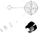
- FIG. 1 is a schematic view showing the function of an LED light source module of the present invention.
- FIG. 2 is a structural diagram of an LED light source module in which the cylindrical metal body A is composed of eight small metal bodies B as an example.
- FIG. 3 is a structural diagram of an LED light source module in which a plurality of small metal bodies B are composed of a polyhedral metal body A as an example.
- the LED light source module directly adopting a metal heat sink as a positive and negative circuit
- the LED light source module includes a metal body A, which may be a regular or irregular shape, and is composed of n Small metal bodies B (B1...Bn) of the same or different shapes and insulated from each other are connected and fixed.
- Each small metal body B has a plurality of identical or different numbers of LED chips C (C1 . . . Cn) on its surface, and adjacent chips are connected in series or in parallel.
- Each small metal body B is provided with a plurality of circuit connection points, and the surface of the small metal body is insulated except for the circuit connection point.
- the LED chip C is directly bonded or soldered to the small metal body B, and at the same time, the silicon dioxide is covered on the chip and its connecting circuit.
- a plurality of positive or negative electrodes can be designed, and the chips on the small metal body B are connected in series or in parallel. It is connected to the positive or negative electrode of other small metal bodies, and can also be connected to an external circuit to form a complete circuit as needed.
- four small metal bodies B constitute a cylindrical metal body A
- LED chips C1, C2 are on the small metal body B1
- LED chips C3, C4 are on the small metal body B2
- LED chips C5, C6 On the small metal body B3, the LED chips C7, C8 are on the small metal body B4, the LED chips C1, C2, C3, C4 are connected in series, the LED chips C5, C6, C7, C8 are connected in series, and then in parallel, the two ends are respectively positive.
- the negative electrode the top surface of the metal body A has a positive electrode B1, a negative electrode B2, a positive electrode B3, and a negative electrode B4, respectively, and the metal body surface has two pairs of corresponding positive and negative electrodes.
- All the chips on the large metal body A are composed of all strings, all of them, after the first string, or before and after the string, and the number of chips on each series or parallel circuit formed by them is symmetrically uniform to ensure uniformity of light output.
- Asymmetric uniform setting for the actual needs, under the premise that the power supply meets the normal operation of the LED chip, Asymmetric uniform setting.
- the LED chip 1, the 8 small metal bodies B 2 and the fixed or circuit connection 3 are combined in a similar manner to that of FIG. 1, and also constitute a cylindrical metal body A, which can be further increased in order to further improve heat dissipation efficiency.
- a number of heat sinks (not shown) are provided.
- a plurality of small metal bodies B constitute a polyhedral metal body A, and the large metal body A is provided with a plurality of through holes or grooves or protrusions as a passage for convection of the heat absorbing air and an increase in the heat dissipation area. It can also be used as a fixed or circuit connection to the outside.
- the present invention can be preferably implemented in accordance with the above embodiments. It should be noted that, based on the above structural design, in order to solve the same technical problem, even if some substantial changes or retouchings are made on the present invention, the essence of the technical solution adopted is still the same as the present invention. Therefore, it should also be within the scope of the present invention.
Abstract
一种直接以金属散热器作为正负极电路的LED光源模块,该LED光源模块,将LED芯片(C)直接固定连接在金属散热器上,同时利用金属散热器本身的良好的导电性能,将散热器分块,根据电路设计的需要,分别作为电路正负极,将芯片(C)连接导通,并与外部电路连接导通形成完整的回路。不用再设计添加另外的PCB电路。该LED光源模块大大方便了电路设计,减少生产工艺,减低生产成本。
Description
本发明属于照明技术领域,具体涉及一种直接以金属散热器作为正负极电路的LED光源模块。
随着科学技术的发展,LED固体照明光源应用日益广泛,将其作为照明光源也越来越多。目前LED照明装置通常包括散热器、LED芯片、PCB板,LED芯片的两个电极以及PCB的两个电路焊盘之间通过导电线连接,此外,由于LED芯片尤其大数目,大功率的LED芯片还有大量热量放出,还需要LED芯片,PCB板,散热器之间的有效热耦合,以实现高效率散热。
发明内容
为了改善上述问题,本发明的目的在于提供一种直接以金属散热器作为正负极电路的LED光源模块。
为了实现上述目的,本发明采用的技术方案如下:
一种直接以金属散热器作为正负极电路的LED光源模块,该LED光源模块包括一个金属体A,所述金属体A由n个相同或不同形状的、相互间绝缘的小金属体B连接固定组成;每个所述小金属体B表面有m个相同或不同数量的LED芯片C,相邻的LED芯片以串联或并联方式连接;
每个所述小金属体B上设有若干个电路连接点,除所述电路连接点外,所述小金属体B表面是绝缘的,所述LED芯片C直接粘接或焊接固定在所述小金属体B上,同时有硅胶覆盖在芯片及其连接电路上;
每个所述小金属体B,根据整体电路的设计需要,均可以设计若干个正极或
者负极,与所述小金属体B上的芯片采用串联或并联或者串联、并联混合的方式连接,并与其它小金属体上正极或者负极相连,也可以与外部电路连接,形成一个所需要的完整的电路;
由若干小金属体B组成的金属体A作为所述LED光源模块的散热器的同时还作为所述LED光源模块的正负极电路;
其中,n≥2,m≥1。
具体地,所述金属体A上所有的芯片形成的每条串联或者并联电路上芯片数量对称均匀或不对称均匀。
具体地,所述金属体A设有若干个通孔或凹槽或凸起,作为散热空气对流的通道以及增加散热面积,或作为与外部连接的固定或电路连接位。
本发明与现有技术相比,具有以下优点及有益效果:
本发明利用金属散热器材料的良导电性,使得该散热器金属模块与外部电路的连接不需要单独设立导电线路,通过将金属散热器分割后的分块之间的绝缘连接工艺的处理,散热器的各个分块直接作为电路连接的正、负极连接导通。
图1为本发明LED光源模块功能示意图。
图2为本发明以8个小金属体B组成圆柱型金属体A为例的LED光源模块结构图。
图3为本发明以若干个小金属体B组成多面体型金属体A为例的LED光源模块结构图。
下面结合附图和实施例对本发明作进一步说明,本发明的实施方式包括但
不限于下列实施例。
实施例
如图1~3所示,一种直接以金属散热器作为正负极电路的LED光源模块,该LED光源模块包括一个金属体A,该金属体A可以是规则或不规则形状,由n个相同或不同形状的、相互间绝缘的小金属体B(B1…Bn)连接固定组成。
每个小金属体B表面有若干个相同或不同数量的LED芯片C(C1…Cn),相邻的芯片以串联或并联方式连接。
每个小金属体B上设有若干个电路连接点,除电路连接点外,小金属体表面是绝缘的。
LED芯片C直接粘接或焊接固定在小金属体B上,同时有硅胶覆盖在芯片及其连接电路上。
每个小金属体B,根据整体电路的设计需要,均可以设计若干个正极或者负极,与小金属体B上的芯片采用串联或并联方式连接。并与其它小金属体上正极或者负极相连,也可以与外部电路连接,形成一个所需要的完整的电路。
如图1所示,四个小金属体B组成了圆柱型的金属体A,LED芯片C1,C2在小金属体B1上,LED芯片C3,C4在小金属体B2上,LED芯片C5,C6在小金属体B3上,LED芯片C7,C8在小金属体B4上,LED芯片C1,C2,C3,C4串联,LED芯片C5,C6,C7,C8串联,然后在并联,两端分别为正极和负极,金属体A顶面分别有正极B1,负极B2,正极B3,负极B4,金属体地面对应有两对相应的正、负极。
组成的大金属体A上所有的芯片无论是全串、全并、先串后并或先并后串,它们最终所形成的每条串联或者并联电路上芯片数量对称均匀以保障出光的均匀,当然为了实际需要,在电源供电满足LED芯片正常工作的前提下,也可以
非对称均匀设置。
如图2所示,LED芯片1,8个小金属体B 2以及固定或电路连接位3按照和图1类似的方式组合,同样组成了圆柱型的金属体A,为了进一步提高散热效率可以增加设置若干散热柱(未用附图标记示出)。
如图3所示,若干个小金属体B组成多面体型金属体A,所组成的大金属体A设有若干个通孔或凹槽或凸起,作为散热空气对流的通道以及增加散热面积,也可以作为与外部连接的固定或电路连接位。
按照上述实施例,便可很好地实现本发明。值得说明的是,基于上述结构设计的前提下,为解决同样的技术问题,即使在本发明上做出的一些无实质性的改动或润色,所采用的技术方案的实质仍然与本发明一样,故其也应当在本发明的保护范围内。
Claims (5)
- 一种直接以金属散热器作为正负极电路的LED光源模块,其特征在于:该LED光源模块包括一个金属体A,所述金属体A由n个相同或不同形状的、相互间绝缘的小金属体B连接固定组成;每个所述小金属体B表面有m个相同或不同数量的LED芯片C,相邻的LED芯片以串联或并联方式连接;每个所述小金属体B上设有若干个电路连接点,除所述电路连接点外,所述小金属体B表面是绝缘的,所述LED芯片C直接粘接或焊接固定在所述小金属体B上,同时有硅胶覆盖在芯片及其连接电路上;每个所述小金属体B,根据整体电路的设计需要,均可以设计若干个正极或者负极,与所述小金属体B上的芯片采用串联或并联或者串联、并联混合的方式连接,并与其它小金属体上正极或者负极相连,也可以与外部电路连接,形成一个所需要的完整的电路;由若干小金属体B组成的金属体A作为所述LED光源模块的散热器的同时还作为所述LED光源模块的正负极电路;其中,n≥2,m≥1。
- 根据权利要求1所述的一种直接以金属散热器作为正负极电路的LED光源模块,其特征在于,所述金属体A上所有的芯片形成的每条串联或者并联电路上芯片数量对称均匀。
- 根据权利要求1所述的一种直接以金属散热器作为正负极电路的LED光源模块,其特征在于,所述金属体A上所有的芯片形成的每条串联或者并联电路上芯片数量不对称均匀。
- 根据权利要求1所述的一种直接以金属散热器作为正负极电路的LED光源模块,其特征在于,所述金属体A设有若干个通孔或凹槽或凸起,作为散热空气对流的通道以及增加散热面积。
- 根据权利要求1所述的一种直接以金属散热器作为正负极电路的LED光源模块,其特征在于,所述金属体A设有若干个通孔或凹槽或凸起,作为与外部连接的固定或电路连接位。
Applications Claiming Priority (2)
| Application Number | Priority Date | Filing Date | Title |
|---|---|---|---|
| CN201610193265.7A CN105627122B (zh) | 2016-03-30 | 2016-03-30 | 一种直接以金属散热器作为正负极电路的led光源模块 |
| CN201610193265.7 | 2016-03-30 |
Publications (1)
| Publication Number | Publication Date |
|---|---|
| WO2017167316A1 true WO2017167316A1 (zh) | 2017-10-05 |
Family
ID=56042309
Family Applications (1)
| Application Number | Title | Priority Date | Filing Date |
|---|---|---|---|
| PCT/CN2017/086237 WO2017167316A1 (zh) | 2016-03-30 | 2017-05-27 | 一种直接以金属散热器作为正负极电路的led光源模块 |
Country Status (2)
| Country | Link |
|---|---|
| CN (1) | CN105627122B (zh) |
| WO (1) | WO2017167316A1 (zh) |
Families Citing this family (7)
| Publication number | Priority date | Publication date | Assignee | Title |
|---|---|---|---|---|
| CN105627122B (zh) * | 2016-03-30 | 2018-11-27 | 湖南粤港模科实业有限公司 | 一种直接以金属散热器作为正负极电路的led光源模块 |
| RU2657864C1 (ru) * | 2016-03-07 | 2018-06-18 | Хунань Юэган Мукрэй Индастриал Ко., Лтд. | Светодиодное осветительное устройство |
| WO2017167314A1 (zh) * | 2016-03-30 | 2017-10-05 | 湖南粤港模科实业有限公司 | 一种模块化灯具 |
| EP3567299A4 (en) * | 2016-06-24 | 2020-01-22 | Hunan Yuegang Mookray Industrial Co., Ltd. | LIGHT EMITTING DIODE LIGHTING DEVICE |
| CN106949443B (zh) * | 2017-04-25 | 2019-04-02 | 湖南粤港模科实业有限公司 | 一种模块化电路、led灯及模块化灯具 |
| CN107202259A (zh) * | 2017-07-14 | 2017-09-26 | 湖南粤港模科实业有限公司 | 一种模块化球泡照明灯具 |
| CN110388613A (zh) * | 2019-08-28 | 2019-10-29 | 东莞好拍档光电科技有限公司 | 负极导电一体化led车灯 |
Citations (7)
| Publication number | Priority date | Publication date | Assignee | Title |
|---|---|---|---|---|
| CN201348233Y (zh) * | 2009-01-12 | 2009-11-18 | 上海三思电子工程有限公司 | Led发光散热体 |
| CN101968213A (zh) * | 2010-09-10 | 2011-02-09 | 谭永生 | 一种led散热装置 |
| CN202024264U (zh) * | 2011-03-31 | 2011-11-02 | 合肥艾斯克光电科技有限责任公司 | Led灯具的复合散热器结构 |
| CN102252279A (zh) * | 2011-04-13 | 2011-11-23 | 广州南科集成电子有限公司 | 热电分离式led集成光源板及其制造方法 |
| KR20150008983A (ko) * | 2013-07-02 | 2015-01-26 | 엘에스엠트론 주식회사 | Led 조명 장치 및 이에 적용되는 커넥터 구조 |
| CN105627122A (zh) * | 2016-03-30 | 2016-06-01 | 朱衡 | 一种直接以金属散热器作为正负极电路的led光源模块 |
| CN205716464U (zh) * | 2016-03-30 | 2016-11-23 | 朱衡 | 一种直接以金属散热器作为正负极电路的led光源模块 |
Family Cites Families (7)
| Publication number | Priority date | Publication date | Assignee | Title |
|---|---|---|---|---|
| JP3998027B2 (ja) * | 2005-07-25 | 2007-10-24 | 松下電工株式会社 | Ledを用いた照明器具 |
| CN101608779A (zh) * | 2008-06-18 | 2009-12-23 | 林恺玉 | 发光元件的散热结构 |
| JP4910023B2 (ja) * | 2009-08-27 | 2012-04-04 | シャープ株式会社 | 光源装置 |
| CN201526932U (zh) * | 2009-11-06 | 2010-07-14 | 陈子文 | 发光二极管元件散热结构 |
| CN101707234A (zh) * | 2009-11-18 | 2010-05-12 | 珠海晟源同泰电子有限公司 | Led发光模组及其制造方法 |
| CN201946597U (zh) * | 2010-12-31 | 2011-08-24 | 浙江天宇灯饰有限公司 | 带有红色led芯片的基于金属平板散热的led装置 |
| CN102569284B (zh) * | 2012-03-16 | 2016-03-30 | 广东科立盈光电技术有限公司 | 新型led发光芯片及其组装形成的led灯 |
-
2016
- 2016-03-30 CN CN201610193265.7A patent/CN105627122B/zh active Active
-
2017
- 2017-05-27 WO PCT/CN2017/086237 patent/WO2017167316A1/zh active Application Filing
Patent Citations (7)
| Publication number | Priority date | Publication date | Assignee | Title |
|---|---|---|---|---|
| CN201348233Y (zh) * | 2009-01-12 | 2009-11-18 | 上海三思电子工程有限公司 | Led发光散热体 |
| CN101968213A (zh) * | 2010-09-10 | 2011-02-09 | 谭永生 | 一种led散热装置 |
| CN202024264U (zh) * | 2011-03-31 | 2011-11-02 | 合肥艾斯克光电科技有限责任公司 | Led灯具的复合散热器结构 |
| CN102252279A (zh) * | 2011-04-13 | 2011-11-23 | 广州南科集成电子有限公司 | 热电分离式led集成光源板及其制造方法 |
| KR20150008983A (ko) * | 2013-07-02 | 2015-01-26 | 엘에스엠트론 주식회사 | Led 조명 장치 및 이에 적용되는 커넥터 구조 |
| CN105627122A (zh) * | 2016-03-30 | 2016-06-01 | 朱衡 | 一种直接以金属散热器作为正负极电路的led光源模块 |
| CN205716464U (zh) * | 2016-03-30 | 2016-11-23 | 朱衡 | 一种直接以金属散热器作为正负极电路的led光源模块 |
Also Published As
| Publication number | Publication date |
|---|---|
| CN105627122A (zh) | 2016-06-01 |
| CN105627122B (zh) | 2018-11-27 |
Similar Documents
| Publication | Publication Date | Title |
|---|---|---|
| WO2017167316A1 (zh) | 一种直接以金属散热器作为正负极电路的led光源模块 | |
| US9412925B2 (en) | High-power LED lamp cooling device and method for manufacturing the same | |
| CN205264758U (zh) | 高散热性led灯丝 | |
| CN205716464U (zh) | 一种直接以金属散热器作为正负极电路的led光源模块 | |
| US9373768B2 (en) | Flip-chip light-emitting diode unit | |
| CN107919338A (zh) | Pcb板led晶片插件组件 | |
| CN209029412U (zh) | 一种led透镜封装结构及led灯具 | |
| TWI432673B (zh) | Led驅動晶片之整合裝置 | |
| CN203386750U (zh) | 一种改进型六颗芯片的led封装结构 | |
| CN204045623U (zh) | 一种改善led灯管光斑的高光效cob柔性灯条 | |
| CN105449091B (zh) | 一种大功率的led封装结构 | |
| CN208589462U (zh) | 一种led灯芯 | |
| CN203799604U (zh) | 一种增强散热的led显示单元模组 | |
| CN203323075U (zh) | 一种led灯散热装置 | |
| CN220249923U (zh) | 一种led灯光源散热装置 | |
| CN208204860U (zh) | 散热型双色cob光源 | |
| CN202432277U (zh) | 一种led光源及led照明装置 | |
| WO2017004973A1 (zh) | 便于安装的珠宝照明用双排灯条 | |
| CN210053639U (zh) | 一种高散热复合线路板 | |
| CN206236707U (zh) | 一种新型cob led光源 | |
| CN207865166U (zh) | 一种节约型照明灯具 | |
| CN201420973Y (zh) | 用于led光源阵列的多芯片集成结构 | |
| CN206595286U (zh) | 一种大功率led元器件 | |
| CN204289532U (zh) | 一种发光二极管贴合散热结构 | |
| CN203718713U (zh) | 一种led灯具 |
Legal Events
| Date | Code | Title | Description |
|---|---|---|---|
| NENP | Non-entry into the national phase |
Ref country code: DE |
|
| 121 | Ep: the epo has been informed by wipo that ep was designated in this application |
Ref document number: 17773345 Country of ref document: EP Kind code of ref document: A1 |
|
| 122 | Ep: pct application non-entry in european phase |
Ref document number: 17773345 Country of ref document: EP Kind code of ref document: A1 |