WO2017164316A1 - 血圧推定装置 - Google Patents
血圧推定装置 Download PDFInfo
- Publication number
- WO2017164316A1 WO2017164316A1 PCT/JP2017/011751 JP2017011751W WO2017164316A1 WO 2017164316 A1 WO2017164316 A1 WO 2017164316A1 JP 2017011751 W JP2017011751 W JP 2017011751W WO 2017164316 A1 WO2017164316 A1 WO 2017164316A1
- Authority
- WO
- WIPO (PCT)
- Prior art keywords
- pulse wave
- wave signal
- blood pressure
- beat
- normal range
- Prior art date
- Legal status (The legal status is an assumption and is not a legal conclusion. Google has not performed a legal analysis and makes no representation as to the accuracy of the status listed.)
- Ceased
Links
Images






Classifications
-
- A—HUMAN NECESSITIES
- A61—MEDICAL OR VETERINARY SCIENCE; HYGIENE
- A61B—DIAGNOSIS; SURGERY; IDENTIFICATION
- A61B5/00—Measuring for diagnostic purposes; Identification of persons
- A61B5/02—Detecting, measuring or recording for evaluating the cardiovascular system, e.g. pulse, heart rate, blood pressure or blood flow
-
- A—HUMAN NECESSITIES
- A61—MEDICAL OR VETERINARY SCIENCE; HYGIENE
- A61B—DIAGNOSIS; SURGERY; IDENTIFICATION
- A61B5/00—Measuring for diagnostic purposes; Identification of persons
- A61B5/02—Detecting, measuring or recording for evaluating the cardiovascular system, e.g. pulse, heart rate, blood pressure or blood flow
- A61B5/021—Measuring pressure in heart or blood vessels
- A61B5/022—Measuring pressure in heart or blood vessels by applying pressure to close blood vessels, e.g. against the skin; Ophthalmodynamometers
Definitions
- the present disclosure relates to a blood pressure estimation device.
- a blood pressure estimation apparatus that acquires a pulse wave signal from a subject using a pulse wave sensor and estimates blood pressure using the pulse wave signal is known.
- the pulse wave signal may contain noise due to poor contact between the pulse wave sensor and the subject. This noise reduces the accuracy of blood pressure estimation.
- the technique described in Patent Document 1 measures the magnitude of noise in a pulse wave signal, and estimates the blood pressure from the pulse wave signal when the noise is small.
- the pulse wave signal may have biologically derived characteristics such as arrhythmia.
- a pulse wave signal having characteristics derived from a living body has a waveform different from that of a normal pulse wave signal.
- a conventional blood pressure estimation device may determine that a pulse wave signal having a characteristic derived from a living body and having a waveform different from a normal one is a pulse signal having a large noise. In that case, it is difficult to appropriately estimate the blood pressure using the pulse wave signal.
- a blood pressure estimation device that can estimate blood pressure using a pulse wave signal even when the pulse wave signal has a characteristic derived from a living body.
- a blood pressure estimation device includes a pulse wave signal acquisition unit that acquires a pulse wave signal of a subject, a feature amount acquisition unit that acquires at least one feature amount for each beat of the pulse wave signal, For each beat of the pulse wave signal, the feature value is normal by the beat determining unit that determines whether or not at least one feature amount is within the normal range and the pulse determining unit of the pulse wave signal.
- a blood pressure estimation unit that estimates a blood pressure using a beat determined to be a beat within a range.
- the characteristic determination unit that determines whether or not the pulse wave signal has characteristics derived from a living body, and the characteristic determination unit that determines that the pulse wave signal has characteristics Includes a normal range setting unit that sets a wider normal range than when the characteristic determination unit determines that the pulse wave signal does not have the characteristic.
- the blood pressure estimation device sets a wide normal range when it is determined that the pulse wave signal has characteristics derived from a living body. And the blood-pressure estimation apparatus which is 1 aspect of this indication judges whether each beat in a pulse wave signal is a beat whose feature-value is in a normal range using the normal range set up widely.
- the blood pressure estimation device can appropriately estimate the blood pressure even when the pulse wave signal has characteristics derived from a living body.
- a blood pressure estimation device includes a pulse wave signal acquisition unit that acquires a pulse wave signal of a subject, a feature amount acquisition unit that acquires a feature amount for each beat of the pulse wave signal, and a pulse wave signal And a beat determination unit that determines whether or not the feature value is within the normal range for each beat, and among the pulse wave signals, the beat is a beat that has the feature value within the normal range by the beat determination unit.
- a ratio calculation unit that calculates the ratio of beats determined to be, and a blood pressure estimation unit that estimates blood pressure using a pulse wave signal on condition that the ratio is equal to or greater than a threshold value.
- the blood pressure estimation device further includes a characteristic determination unit that determines whether or not the pulse wave signal has a characteristic derived from a living body, and the characteristic determination unit that the pulse wave signal has a characteristic.
- a threshold value setting unit that makes the threshold value smaller than when the characteristic determination unit determines that the pulse wave signal does not have the characteristic.
- the blood pressure estimation device sets the threshold value to be small when it is determined that the pulse wave signal has characteristics derived from a living body. And the blood-pressure estimation apparatus which is another aspect of this indication judges whether the ratio is more than a threshold using the threshold set small.
- the blood pressure estimation device may be configured so that even if the pulse wave signal has a characteristic derived from a living body, the pulse wave signal that is actually low in noise is “the ratio is less than the threshold”. It can suppress that it judges. As a result, the blood pressure estimation device according to another aspect of the present disclosure can appropriately estimate the blood pressure even when the pulse wave signal has characteristics derived from a living body.
- FIG. 6 is an explanatory diagram showing feature amounts F1 to F11 and normal ranges R1 and R2. It is a block diagram showing the functional structure of a control part. It is a flowchart showing the process which a blood-pressure estimation apparatus performs. It is explanatory drawing showing the width
- the blood pressure estimation device 1 includes a control unit 3, a pulse wave sensor 5, a start switch 6, and a display 7.
- the control unit 3 is mainly configured by a known microcomputer having a CPU 9 and a semiconductor memory (hereinafter referred to as a memory 11) such as a RAM, a ROM, and a flash memory.
- a memory 11 such as a RAM, a ROM, and a flash memory.
- Various functions of the control unit 3 are realized by the CPU 9 executing a program stored in a non-transitional physical recording medium.
- the memory 11 corresponds to a non-transitional tangible recording medium that stores a program. Further, by executing this program, a method corresponding to the program is executed.
- the number of microcomputers constituting the control unit 3 may be one or more.
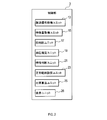
- the control unit 3 includes a pulse wave signal acquisition unit 13, a feature amount acquisition unit 15, a pulse determination unit 17, a blood pressure as a function configuration realized by the CPU 9 executing a program.
- An estimation unit 19, a characteristic determination unit 21, a normal range setting unit 23, a ratio calculation unit 25, and a display unit 26 are provided.
- the method of realizing these elements constituting the control unit 3 is not limited to software, and some or all of the elements may be realized using hardware that combines a logic circuit, an analog circuit, and the like.
- the pulse wave sensor 5 is a well-known sensor capable of detecting a pulse wave signal from the subject's finger.
- the pulse wave sensor 5 includes a light emitting diode 27 and a photodiode 29.
- the light emitting diode is denoted as LED
- the photodiode is denoted as PD.
- the light emitting diode 27 irradiates the skin on the subject's finger with visible light. The wavelength of this light is 5000 to 7000 mm. A part of the light emitted by the light emitting diode 27 is reflected in the capillaries of the skin.
- the photodiode 29 receives light reflected in the capillaries out of the light emitted from the light emitting diode 27 and extracts it as an electrical signal.
- the extracted electrical signal is a pulse wave signal that varies to reflect the pulse wave of the subject.
- the start switch 6 is a switch that is turned on when the pulse wave sensor 5 is pressed with the finger of the subject. When the start switch 6 is turned on, processing described later is executed.
- the display 7 can display an image based on a signal sent from the control unit 3.
- the blood pressure estimation device 1 includes a housing 31.
- the pulse wave sensor 5 and the display 7 are attached to the housing 31.
- the subject can bring the finger 33 into contact with the pulse wave sensor 5.
- the pulse wave sensor 5 detects a pulse wave signal from the finger 33.
- step 1 of FIG. 4 the pulse wave signal acquisition unit 13 acquires the pulse wave signal of the subject using the pulse wave sensor 5.
- the feature amount acquisition unit 15 acquires two types of feature amounts for each beat of the pulse wave signal acquired in step 1.
- the two types of feature amounts acquired in this step are used later to determine whether or not the pulse wave signal acquired in step 1 corresponds to an arrhythmia.
- arrhythmia determination feature amounts Arrhythmias correspond to biologically derived characteristics.
- One type of arrhythmia determination feature amount is a peak-to-peak interval (hereinafter referred to as a PP interval) shown in FIG.
- the PP interval is the length of one beat in the pulse wave signal 35.
- the unit of the PP interval is time.
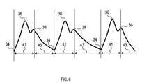
- the slope X is the slope of the pulse wave signal in the section from the pulse wave start point 34 to the first peak 36 shown in FIG.
- the first peak 36 is a peak that appears first after the pulse group start point 34.
- the feature amount acquisition unit 15 acquires a feature amount different from the arrhythmia determination feature amount for each beat of the pulse wave signal acquired in step 1. This feature amount is used for determination in step 10 described later.
- the feature amount acquired in this step is hereinafter referred to as a noise determination feature amount.
- the noise determination feature amount can be selected as appropriate. For example, the height of any one of the known feature points a, b, c, d, e shown in FIG. 7 or the feature points a, b, c, d, e from the acceleration pulse wave The time until one of the above can be used as a noise determination feature amount.
- a waveform 37 shown in FIG. 7 is a differential signal of the pulse wave signal acquired in step 1. Further, P2 / P1 may be used as the noise determination feature amount.
- P1 is the peak height of the traveling wave
- P2 is the peak height of the reflected wave.
- the characteristic determination unit 21 calculates an index (hereinafter referred to as a PP interval variation index) representing the magnitude of the PP interval variation acquired in step 2.
- the PP interval variation index is calculated as follows. Since the PP interval is acquired for each beat, there are the number N of all beats in the pulse wave signal. First, a median value in N PP intervals is calculated. Next, a lower limit value obtained by multiplying the median value by 0.7 and an upper limit value obtained by multiplying the median value by 1.3 are calculated. Next, the number n of PP intervals out of the range from the upper limit value to the lower limit value among the N PP intervals is calculated. Let n / N be the PP interval variation index. The larger the value of the PP interval variation index, the larger the PP interval variation.
- the characteristic determination unit 21 calculates an index (hereinafter referred to as an inclination X variation index) indicating the magnitude of the variation in the inclination X acquired in step 2.
- the slope X variation index is calculated as follows. Since the slope X is acquired for each beat, there are the number N of beats in the pulse wave signal. First, a median value for N slopes X is calculated. Next, a lower limit value obtained by multiplying the median value by 0.7 and an upper limit value obtained by multiplying the median value by 1.3 are calculated. Next, out of the N slopes X, the number m of the slopes X outside the range from the upper limit value to the lower limit value is calculated. Let m / N be the slope X variation index. As the value of the slope X variation index is larger, the variation in the slope X is larger.
- step 6 the normal range setting unit 23 calculates the median value F c of the noise determination feature amount acquired in step 3.
- the median F c means a median of the N noise determination feature quantity.
- the characteristic determination unit 21 determines whether or not the pulse wave signal acquired in step 1 corresponds to an arrhythmia. Specifically, the characteristic determination unit 21 determines that the pulse wave signal acquired in step 1 corresponds to an arrhythmia if both of the following conditions (a) and (b) are satisfied: (a) , (B), if neither is satisfied, it is determined that the pulse wave signal acquired in step 1 does not correspond to an arrhythmia.
- the reference value Va and the reference value Vb are positive numbers.
- the size of the PP interval variation index calculated in step 4 is equal to or greater than a preset reference value Va.
- the magnitude of the gradient X variation index calculated in step 5 is equal to or less than a preset reference value Vb.
- step 8 the normal range setting unit 23 sets the normal range R1.
- the normal range R1 is a range having 0.5 ⁇ median value Fc as a lower limit and 1.5 ⁇ median value Fc as an upper limit.
- the median value F c is the value calculated in step 6 above.
- the normal range R1 is a range wider than a normal range R2 described later.
- the normal range setting unit 23 sets the normal range R2.
- the normal range R2 is a range having 0.8 ⁇ median value Fc as a lower limit value and 1.2 ⁇ median value Fc as an upper limit value.
- the normal range R2 is a range narrower than the normal range R1.
- the median value F c is the value calculated in step 6 above.
- the beat determination unit 17 determines whether or not the beat is a normal beat for each beat of the pulse wave signal acquired in step 1.
- a normal beat is a beat whose noise determination feature value is within the normal range.
- the normal range used for the determination is the normal range R1 when the normal range R1 is set in Step 8, and is the normal range R2 when the normal range R2 is set in Step 9.
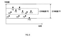
- FIG. 8 shows an example of the above judgment.
- F1 to F11 are noise determination feature amounts of one beat.
- the normal range is the normal range R1
- the beats corresponding to F1 to F11 are normal beats.
- the normal range is the normal range R2
- the beats corresponding to F2, F4, F7, F9, and F11 are normal beats, and the other beats are not normal beats.
- the ratio calculation unit 25 calculates the ratio of the pulse wave signal occupied by the beat determined to be a normal beat in step 10. This ratio is expressed as p / N. p is the number of beats determined to be normal beats in the step 10 in the pulse wave signal. As described above, N is the number of all beats in the pulse wave signal.
- step 12 the blood pressure estimation unit 19 determines whether or not the ratio calculated in step 11 is equal to or greater than a threshold value.
- the threshold used for the determination is a fixed value set in advance. If the ratio is greater than or equal to the threshold, the process proceeds to step 13, and if the ratio is less than the threshold, the process proceeds to step 15.
- step 13 the blood pressure estimation unit 19 estimates the blood pressure using a normal beat by a known method.
- step 14 the display unit 26 displays the blood pressure estimated in step 13 on the display 7. If it is determined in step 7 that it corresponds to an arrhythmia, the display unit 26 displays on the display 7 an image indicating that it corresponds to an arrhythmia in addition to the estimated blood pressure.
- step 15 the display unit 26 displays a message “Measurement is unstable. Please place your finger again” on the display 7. 3. Effects exhibited by the blood pressure estimation device 1 (1A) When the blood pressure estimation device 1 determines that the pulse wave signal corresponds to an arrhythmia, the normal range R1 is set. And the blood-pressure estimation apparatus 1 judges whether each beat in a pulse wave signal is a normal beat using the normal range R1.
- the blood pressure estimation device 1 can appropriately estimate the blood pressure even when the pulse wave signal corresponds to an arrhythmia.
- the blood pressure estimation device 1 determines that the pulse wave signal corresponds to an arrhythmia when both the above-described conditions (a) and (b) are satisfied.
- the above (a) and (b) are conditions that are easily satisfied when the pulse wave signal corresponds to an arrhythmia.
- the above (b) is a condition that does not correspond to an arrhythmia and is difficult to satisfy with a pulse wave signal having a large noise.
- Second Embodiment 1 Differences from the First Embodiment Since the basic configuration of the second embodiment is the same as that of the first embodiment, description of the common configuration will be omitted, and differences will be mainly described. Note that the same reference numerals as those in the first embodiment indicate the same configuration, and the preceding description is referred to.
- control unit 3 includes a threshold value setting unit 39 instead of the normal range setting unit 23 in the first embodiment. 2. Processing Performed by Blood Pressure Estimation Device 1 Processing performed by blood pressure estimation device 1 will be described with reference to FIG. This process is executed when the start switch 6 is turned on. Steps 21 to 26 are the same as steps 1 to 6 in the first embodiment.
- the normal range setting unit 23 sets the normal range R2.
- the normal range R2 is a range having 0.8 ⁇ median value Fc as a lower limit value and 1.2 ⁇ median value Fc as an upper limit value.
- the median value F c is the value calculated in step 26.
- the normal range R1 is not set.
- step 28 the beat determination unit 17 determines whether or not the beat is a normal beat for each beat of the pulse wave signal acquired in step 21.
- the normal range used for the determination is the normal range R2 set in step 27.
- the ratio calculation unit 25 calculates the ratio of the pulse wave signal to the beats determined to be normal beats in step 28. This ratio is expressed as p / N. p is the number of beats determined to be normal beats in step 27 in the pulse wave signal. As described above, N is the number of all beats in the pulse wave signal.
- step 30 the characteristic determination unit 21 determines whether or not the pulse wave signal acquired in step 21 corresponds to an arrhythmia.
- the determination method is the same as in step 7 in the first embodiment. If it is determined that the pulse wave signal acquired in step 21 corresponds to an arrhythmia, the process proceeds to step 31, and if it is determined that it does not correspond to an arrhythmia, the process proceeds to step 32.
- the threshold setting unit 39 sets a threshold T1.
- the threshold value T1 is a value smaller than a threshold value T2 described later.
- the threshold value T1 can be set to 0.3, for example.
- the threshold setting unit 39 sets the threshold T2.
- the threshold value T2 is a value larger than the threshold value T1.
- the threshold T2 can be set to 0.5, for example.
- step 33 the blood pressure estimation unit 19 determines whether or not the ratio calculated in step 29 is greater than or equal to a threshold value.
- the threshold value used for the determination is the threshold value T1 when the threshold value is set in step 31, and is the threshold value T2 when the threshold value is set in step 32. If the ratio is greater than or equal to the threshold, the process proceeds to step 34, and if the ratio is less than the threshold, the process proceeds to step 36.
- step 34 the blood pressure estimation unit 19 estimates the blood pressure by a known method using the normal beat.
- step 35 the display unit 26 displays the blood pressure estimated in step 34 on the display 7. If it is determined in step 30 that the arrhythmia is met, the display unit 26 displays an image representing the arrhythmia on the display 7 in addition to the estimated blood pressure.
- step 36 the display unit 26 displays a message “Measurement is unstable. Please place your finger again” on the display 7. 3. Effects exhibited by the blood pressure estimation device 1 According to the second embodiment described in detail above, the following effects are obtained in addition to the effects (1B) of the first embodiment described above.
- the blood pressure estimation device 1 sets a threshold value T1 when determining that the pulse wave signal corresponds to an arrhythmia. And the blood-pressure estimation apparatus 1 judges whether the ratio of a normal beat is more than a threshold value using threshold value T1.
- the blood pressure estimation device 1 can appropriately estimate the blood pressure even when the pulse wave signal corresponds to an arrhythmia.
- the basic configuration of the third embodiment is the same as that of the first embodiment, the description of the common configurations will be omitted, and differences will be mainly described. Note that the same reference numerals as those in the first embodiment indicate the same configuration, and the preceding description is referred to.
- the feature amount acquisition unit 15 acquires two or more types of noise determination feature amounts for each beat of the pulse wave signal.
- the two or more types of noise determination feature amounts include a noise determination feature amount related to a period from the pulse start point 34 to the notch 38 (hereinafter referred to as a first period) and a period other than that (hereinafter referred to as a second period). Noise determination feature amount).
- FIG. 6 shows the pulse start point 34, the notch 38, the first period 41, and the second period 43.
- Notch means aortic valve closure.
- the noise determination feature quantity for the first period is referred to as a first noise determination feature quantity
- the other noise determination feature quantities are referred to as second noise determination feature quantities.
- the first noise determination feature means a waveform from the heart.
- the first noise determination feature amount for example, the time until the first peak is cited.
- the second noise determination feature amount include the slope of the pulse wave signal after the notch.
- step 6 the normal range setting unit 23, for each of two or more noise determination feature quantity, and calculates the median value F c.
- the normal range setting unit 23 sets the normal range R1 or the normal range R2 for each of the two or more types of noise determination feature quantities.
- the ratio of the width of the normal range R1 to the width of the normal range R2 is different between the first noise determination feature amount and the second noise determination feature amount.
- the difference between the width of the normal range R1 and the width of the normal range R2 is small for the first noise determination feature amount. Both widths may be the same.
- the difference between the width of the normal range R1 and the width of the normal range R2 is large. That is, the first noise determination feature amount is smaller than the second noise determination feature amount to the extent that the normal range R1 is expanded compared to the normal range R2.
- the beat determination unit 17 determines whether or not the noise determination feature amount is within the normal range for each of the two or more types of noise determination feature amounts. When all of the two or more types of noise determination feature values in a certain beat are within the normal range, the beat is determined as a normal beat. On the other hand, if at least one of the two or more types of noise determination feature values in a certain beat is outside the normal range, it is determined that the beat is not a normal beat.
- the blood pressure estimation device 1 acquires two or more types of noise determination feature quantities for each beat of the pulse wave signal. In addition, the blood pressure estimation device 1 sets a normal range for each of the two or more types of noise determination feature quantities. Then, the blood pressure estimation device 1 determines that a beat in which two or more types of noise determination feature quantities are within the normal range is a normal beat. As a result, the blood pressure estimation device 1 can more accurately determine whether or not it is a normal beat.
- the blood pressure estimation device 1 can more accurately determine whether or not it is a normal beat.
- a case is assumed in which it is determined whether or not the first noise determination feature amount is within a normal range in a situation where the pulse wave signal corresponds to an arrhythmia.
- the normal range R1 used in this case is not so wide compared to the normal range R2. For this reason, it is possible to suppress erroneously determining that a beat having actually large noise is “the first noise determination feature value is within the normal range”.
- the first noise determination feature amount is unlikely to fluctuate. Therefore, even if the normal range R1 used for the determination regarding the first noise determination feature amount is relatively narrow, “the first noise determination feature amount is not within the normal range” for a beat with a small noise actually. It is unlikely to make a mistake. ⁇ Other embodiments> As mentioned above, although the form for implementing this indication was demonstrated, this indication is not limited to the above-mentioned embodiment, and can carry out various modifications.
- step 7 in the first and third embodiments, and step 30 in the second embodiment it may be determined whether or not it has characteristics derived from a living body other than arrhythmia.
- characteristics derived from living bodies other than arrhythmia include hypoperfusion.
- Hypoperfusion is a characteristic associated with vascular stenosis or heart failure. Hypoperfusion is a condition in which blood does not reach the periphery. When hypoperfusion, the pulse amplitude in the pulse signal is significantly reduced. As a result, the pulse signal becomes weak and noise increases.
- the pulse amplitude is acquired continuously. If the pulse amplitude is equal to or lower than the preset threshold value, the perfusion is determined to be low perfusion if it continues for a preset time or longer, otherwise it is determined not to be low perfusion. Can do.
- step 34 of the second embodiment blood pressure may be estimated using not only normal beats but all beats.
- Step 7 of the first and third embodiments and Step 30 of the second embodiment it may be determined whether or not an arrhythmia is satisfied by another method. For example, if (a) is satisfied, it may be determined that the arrhythmia is satisfied, and if (a) is not satisfied, it may be determined that the arrhythmia is not satisfied.
- the index representing the PP interval and the variation in the slope X may be other than those described above.
- standard deviation or the like can be used as an index representing variation.
- a plurality of functions of one constituent element in the above embodiment may be realized by a plurality of constituent elements, or a single function of one constituent element may be realized by a plurality of constituent elements. .
- a plurality of functions possessed by a plurality of constituent elements may be realized by one constituent element, or one function realized by a plurality of constituent elements may be realized by one constituent element.
- at least a part of the configuration of the above embodiment may be added to or replaced with the configuration of the other embodiment.
- all the aspects included in the technical idea specified only by the wording described in the claims are embodiments of the present disclosure.
- a system including the blood pressure estimation device as a constituent element, a program for causing a computer to function as the control unit 3, and a non-transitional actual recording medium such as a semiconductor memory storing the program can also be realized in various forms such as a blood pressure estimation method, an arrhythmia determination method, and a noise determination method.
Landscapes
- Health & Medical Sciences (AREA)
- Life Sciences & Earth Sciences (AREA)
- Cardiology (AREA)
- Medical Informatics (AREA)
- Surgery (AREA)
- Biophysics (AREA)
- Pathology (AREA)
- Engineering & Computer Science (AREA)
- Biomedical Technology (AREA)
- Heart & Thoracic Surgery (AREA)
- Physiology (AREA)
- Molecular Biology (AREA)
- Physics & Mathematics (AREA)
- Animal Behavior & Ethology (AREA)
- General Health & Medical Sciences (AREA)
- Public Health (AREA)
- Veterinary Medicine (AREA)
- Vascular Medicine (AREA)
- Ophthalmology & Optometry (AREA)
- Measuring Pulse, Heart Rate, Blood Pressure Or Blood Flow (AREA)
Abstract
血圧推定装置(1)は、脈波信号取得ユニット(13)と、特徴量取得ユニット(15)と、拍判断ユニット(17)と、血圧推定ユニット(19)と、特性判断ユニット(21)と、正常範囲設定ユニット(23)と、を備える。脈波信号取得ユニットは、被験者の脈波信号を取得する。特徴量取得ユニットは、脈波信号の1拍ごとに特徴量を取得する。拍判断ユニットは、脈波信号の1拍ごとに、特徴量が正常範囲内にある拍であるか否かを判断する。血圧推定ユニットは、脈波信号のうち、特徴量が正常範囲内にある拍であると判断された拍を用いて血圧を推定する。特性判断ユニットは、脈波信号が生体由来の特性を有するか否かを判断する。正常範囲設定ユニットは、脈波信号が特性を有すると判断した場合は、それ以外の場合よりも、正常範囲を広く設定する。
Description
本国際出願は、2016年3月24日に日本国特許庁に出願された日本国特許出願第2016-059856号に基づく優先権を主張するものであり、日本国特許出願第2016-059856号の全内容を本国際出願に参照により援用する。
本開示は血圧推定装置に関する。
従来、脈波センサを用いて被験者から脈波信号を取得し、その脈波信号を用いて血圧を推定する血圧推定装置が知られている。脈波センサと被験者との接触不良等に起因して、脈波信号がノイズを含むことがある。このノイズは、血圧推定の精度を低下させる。特許文献1に記載の技術は、脈波信号におけるノイズの大きさを測定し、ノイズが小さい場合に、脈波信号から血圧を推定する。
発明者の詳細な検討の結果、以下の課題が見出された。脈波信号は、不整脈等、生体由来の特性を有することがある。生体由来の特性を有する脈波信号は、通常の脈波信号とは波形が異なる。従来の血圧推定装置は、生体由来の特性を有し、波形が通常とは異なる脈波信号を、ノイズが大きい脈派信号であると判断してしまうおそれがある。その場合、脈波信号を用いて血圧を適切に推定することが困難になる。
本開示の一局面は、脈波信号が生体由来の特性を有する場合でも、脈波信号を用いて血圧を推定することができる血圧推定装置を提供することが好ましい。
本開示の一態様である血圧推定装置は、被験者の脈波信号を取得する脈波信号取得ユニットと、脈波信号の1拍ごとに少なくとも1種の特徴量を取得する特徴量取得ユニットと、脈波信号の1拍ごとに、少なくとも1種の特徴量が正常範囲内にある拍であるか否かを判断する拍判断ユニットと、脈波信号のうち、拍判断ユニットにより、特徴量が正常囲内にある拍であると判断された拍を用いて血圧を推定する血圧推定ユニットとを備える。
本開示の一態様である血圧推定装置は、被験者の脈波信号を取得する脈波信号取得ユニットと、脈波信号の1拍ごとに少なくとも1種の特徴量を取得する特徴量取得ユニットと、脈波信号の1拍ごとに、少なくとも1種の特徴量が正常範囲内にある拍であるか否かを判断する拍判断ユニットと、脈波信号のうち、拍判断ユニットにより、特徴量が正常囲内にある拍であると判断された拍を用いて血圧を推定する血圧推定ユニットとを備える。
本開示の一態様である血圧推定装置は、さらに、脈波信号が生体由来の特性を有するか否かを判断する特性判断ユニットと、脈波信号が特性を有すると特性判断ユニットが判断した場合は、前記脈波信号が前記特性を有さないと前記特性判断ユニットが判断した場合よりも、正常範囲を広く設定する正常範囲設定ユニットとを備える。
本開示の一態様である血圧推定装置は、脈波信号が生体由来の特性を有すると判断した場合、正常範囲を広く設定する。そして、本開示の一態様である血圧推定装置は、広く設定された正常範囲を用いて、脈波信号における各拍が、特徴量が正常範囲内にある拍であるか否かを判断する。
そのことにより、本開示の一態様である血圧推定装置は、脈波信号が生体由来の特性を有する場合でも、実際にはノイズが小さい拍を、「特徴量が正常範囲内にはない拍」と判断してしまうことを抑制できる。その結果、本開示の一態様である血圧推定装置は、脈波信号が生体由来の特性を有する場合でも、血圧を適切に推定することができる。
本開示の別の態様である血圧推定装置は、被験者の脈波信号を取得する脈波信号取得ユニットと、脈波信号の1拍ごとに特徴量を取得する特徴量取得ユニットと、脈波信号の1拍ごとに、特徴量が正常範囲内にある拍であるか否かを判断する拍判断ユニットと、脈波信号のうち、拍判断ユニットにより、特徴量が正常範囲内にある拍であると判断された拍が占める比率を算出する比率算出ユニットと、比率が閾値以上であることを条件として、脈波信号を用いて血圧を推定する血圧推定ユニットとを備える。
本開示の別の態様である血圧推定装置は、さらに、脈波信号が生体由来の特性を有するか否かを判断する特性判断ユニットと、脈波信号が特性を有すると特性判断ユニットが判断した場合は、前記脈波信号が前記特性を有さないと前記特性判断ユニットが判断した場合よりも、閾値を小さくする閾値設定ユニットとを備える。
本開示の別の態様である血圧推定装置は、脈波信号が生体由来の特性を有すると判断した場合、閾値を小さく設定する。そして、本開示の別の態様である血圧推定装置は、小さく設定された閾値を用いて、前記比率が閾値以上であるか否かを判断する。
そのことにより、本開示の別の態様である血圧推定装置は、脈波信号が生体由来の特性を有する場合でも、実際にはノイズが小さい脈波信号を、「前記比率が閾値未満である」と判断してしまうことを抑制できる。その結果、本開示の別の態様である血圧推定装置は、脈波信号が生体由来の特性を有する場合でも、血圧を適切に推定することができる。
なお、特許請求の範囲に記載した括弧内の符号は、一つの態様として後述する実施形態に記載の具体的手段との対応関係を示すものであって、本開示の技術的範囲を限定するものではない。
本開示の実施形態を図面に基づき説明する。
<第1実施形態>
1.血圧推定装置1の構成
血圧推定装置1の構成を図1~図3に基づき説明する。血圧推定装置1は、図1に示すように、制御部3と、脈波センサ5と、開始スイッチ6と、ディスプレイ7とを備える。制御部3は、CPU9と、RAM、ROM、フラッシュメモリ等の半導体メモリ(以下、メモリ11とする)と、を有する周知のマイクロコンピュータを中心に構成される。制御部3の各種機能は、CPU9が非遷移的実体的記録媒体に格納されたプログラムを実行することにより実現される。この例では、メモリ11が、プログラムを格納した非遷移的実体的記録媒体に該当する。また、このプログラムの実行により、プログラムに対応する方法が実行される。なお、制御部3を構成するマイクロコンピュータの数は1つでも複数でもよい。
<第1実施形態>
1.血圧推定装置1の構成
血圧推定装置1の構成を図1~図3に基づき説明する。血圧推定装置1は、図1に示すように、制御部3と、脈波センサ5と、開始スイッチ6と、ディスプレイ7とを備える。制御部3は、CPU9と、RAM、ROM、フラッシュメモリ等の半導体メモリ(以下、メモリ11とする)と、を有する周知のマイクロコンピュータを中心に構成される。制御部3の各種機能は、CPU9が非遷移的実体的記録媒体に格納されたプログラムを実行することにより実現される。この例では、メモリ11が、プログラムを格納した非遷移的実体的記録媒体に該当する。また、このプログラムの実行により、プログラムに対応する方法が実行される。なお、制御部3を構成するマイクロコンピュータの数は1つでも複数でもよい。
制御部3は、CPU9がプログラムを実行することで実現される機能の構成として、図2に示すように、脈波信号取得ユニット13と、特徴量取得ユニット15と、拍判断ユニット17と、血圧推定ユニット19と、特性判断ユニット21と、正常範囲設定ユニット23と、比率算出ユニット25と、表示ユニット26と、を備える。制御部3を構成するこれらの要素を実現する手法はソフトウェアに限るものではなく、その一部又は全部の要素を、論理回路やアナログ回路等を組み合わせたハードウェアを用いて実現してもよい。
脈波センサ5は、被験者の指から脈波信号を検出可能な周知のセンサである。脈波センサ5は、発光ダイオード27とフォトダイオード29とを備える。図1では、発光ダイオードをLEDと表記し、フォトダイオードをPDと表記する。発光ダイオード27は、被験者の指における皮膚に対して可視光の光を照射する。この光の波長は、5000Å~7000Åである。発光ダイオード27が照射した光の一部は皮膚の毛細血管内において反射される。フォトダイオード29は、発光ダイオード27が照射した光のうち、毛細血管内で反射された光を受光し、電気信号として取り出す。取り出した電気信号は、被験者の脈波を反映して変動する脈波信号である。
開始スイッチ6は、脈波センサ5を被験者の指で押圧するとオンになるスイッチである。開始スイッチ6がオンになったとき、後述する処理が実行される。ディスプレイ7は、制御部3から送られる信号に基づき画像を表示することができる。
図3に示すように、血圧推定装置1は、筐体31を備える。脈波センサ5及びディスプレイ7は筐体31に取り付けられている。被験者は、指33を脈波センサ5に接触させることができる。このとき、脈波センサ5は指33から脈波信号を検出する。
2.血圧推定装置1が実行する処理
血圧推定装置1が実行する処理を図4~図8に基づき説明する。この処理は、開始スイッチ6がオンになったときに実行される。
血圧推定装置1が実行する処理を図4~図8に基づき説明する。この処理は、開始スイッチ6がオンになったときに実行される。
図4のステップ1では、脈波信号取得ユニット13が、脈波センサ5を用いて、被験者の脈波信号を取得する。
ステップ2では、特徴量取得ユニット15が、前記ステップ1で取得した脈波信号の1拍ごとに、2種類の特徴量を取得する。本ステップで取得する2種類の特徴量は、後に、前記ステップ1で取得した脈波信号が不整脈に該当するか否かの判断に用いられる。以下では、この2種類の特徴量を不整脈判断用特徴量とする。不整脈は、生体由来の特性に対応する。
ステップ2では、特徴量取得ユニット15が、前記ステップ1で取得した脈波信号の1拍ごとに、2種類の特徴量を取得する。本ステップで取得する2種類の特徴量は、後に、前記ステップ1で取得した脈波信号が不整脈に該当するか否かの判断に用いられる。以下では、この2種類の特徴量を不整脈判断用特徴量とする。不整脈は、生体由来の特性に対応する。
不整脈判断用特徴量のうちの1種は、図5に示すピークツウピーク間隔(以下ではPP間隔とする)である。PP間隔は、脈波信号35における1拍の長さである。PP間隔の単位は時間である。
不整脈判断用特徴量のうちの他の1種は、傾きXである。傾きXとは、図6に示す脈派開始点34から第1ピーク36までの区間における脈派信号の傾きである。第1ピーク36とは、脈派開始点34の後に最初に表れるピークである。
ステップ3では、特徴量取得ユニット15が、前記ステップ1で取得した脈波信号の1拍ごとに、不整脈判断用特徴量とは別の特徴量を取得する。この特徴量は、後述するステップ10での判断に使用される。本ステップで取得する特徴量を、以下では、ノイズ判断用特徴量とする。ノイズ判断用特徴量は、適宜選択できる。例えば、図7に示す周知の特徴点a、b、c、d、eのうちのいずれかの特徴点の高さ、又は、加速度脈波から特徴点a、b、c、d、eのうちのいずれかまでの時間を、ノイズ判断用特徴量とすることができる。図7に示す波形37は、前記ステップ1で取得した脈波信号の微分信号である。また、P2/P1をノイズ判断用特徴量としてもよい。P1は進行波のピーク高さであり、P2は反射波のピーク高さである。
ステップ4では、特性判断ユニット21が、前記ステップ2で取得したPP間隔のばらつきの大きさを表す指標(以下ではPP間隔ばらつき指標とする)を算出する。PP間隔ばらつき指標は、以下のように算出される。PP間隔は、1拍ごとに取得されているので、脈波信号における全ての拍の数Nだけ存在する。まず、N個のPP間隔における中央値を算出する。次に、その中央値に0.7を乗算した下限値と、中央値に1.3を乗算した上限値とを算出する。次に、N個のPP間隔のうち、上限値から下限値までの範囲の外にあるPP間隔の数nを算出する。n/Nを、PP間隔ばらつき指標とする。PP間隔ばらつき指標の値が大きいほど、PP間隔のばらつきは大きい。
ステップ5では、特性判断ユニット21が、前記ステップ2で取得した傾きXのばらつきの大きさを表す指標(以下では傾きXばらつき指標とする)を算出する。傾きXばらつき指標は、以下のように算出される。傾きXは、1拍ごとに取得されているので、脈波信号における拍の数Nだけ存在する。まず、N個の傾きXにおける中央値を算出する。次に、その中央値に0.7を乗算した下限値と、中央値に1.3を乗算した上限値とを算出する。次に、N個の傾きXのうち、上限値から下限値までの範囲の外にある傾きXの数mを算出する。m/Nを、傾きXばらつき指標とする。傾きXばらつき指標の値が大きいほど、傾きXのばらつきは大きい。
ステップ6では、正常範囲設定ユニット23が、前記ステップ3で取得したノイズ判断用特徴量の中央値Fcを算出する。なお、上述したように、ノイズ判断用特徴量は1拍ごとに取得されているので、脈波信号における拍の数Nだけ存在する。中央値Fcとは、N個のノイズ判断用特徴量における中央値を意味する。
ステップ7では、前記ステップ1で取得した脈波信号が不整脈に該当するか否かを、特性判断ユニット21が判断する。具体的には、特性判断ユニット21は、以下の(a)、(b)の両方の条件が充足されれば、前記ステップ1で取得した脈波信号は不整脈に該当すると判断し、(a)、(b)のうち、一方でも充足されなければ、前記ステップ1で取得した脈波信号は不整脈に該当しないと判断する。基準値Va、基準値Vbは正の数である。
(a)前記ステップ4で算出したPP間隔ばらつき指標の大きさが予め設定された基準値Va以上である。
(b)前記ステップ5で算出した傾きXばらつき指標の大きさが予め設定された基準値Vb以下である。
(b)前記ステップ5で算出した傾きXばらつき指標の大きさが予め設定された基準値Vb以下である。
不整脈に該当すると判断した場合はステップ8に進み、不整脈に該当しないと判断した場合はステップ9に進む。
ステップ8では、正常範囲設定ユニット23が、正常範囲R1を設定する。正常範囲R1とは、0.5×中央値Fcを下限値とし、1.5×中央値Fcを上限値とする範囲である。中央値Fcは前記ステップ6で算出した値である。正常範囲R1は、後述する正常範囲R2よりも広い範囲である。
ステップ8では、正常範囲設定ユニット23が、正常範囲R1を設定する。正常範囲R1とは、0.5×中央値Fcを下限値とし、1.5×中央値Fcを上限値とする範囲である。中央値Fcは前記ステップ6で算出した値である。正常範囲R1は、後述する正常範囲R2よりも広い範囲である。
ステップ9では、正常範囲設定ユニット23が、正常範囲R2を設定する。正常範囲R2とは、0.8×中央値Fcを下限値とし、1.2×中央値Fcを上限値とする範囲である。正常範囲R2は、正常範囲R1よりも狭い範囲である。中央値Fcは前記ステップ6で算出した値である。
ステップ10では、拍判断ユニット17が、前記ステップ1で取得した脈波信号の1拍ごとに、その拍が正常拍であるか否かを判断する。正常拍とは、その拍のノイズ判断用特徴量が、正常範囲内にある拍である。判断に用いる正常範囲は、前記ステップ8で正常範囲R1を設定した場合は、正常範囲R1であり、前記ステップ9で正常範囲R2を設定した場合は、正常範囲R2である。
図8に、上記の判断の例を示す。図8において、F1~F11は、それぞれ、1拍のノイズ判断用特徴量である。正常範囲が正常範囲R1である場合、F1~F11に対応する拍は、正常拍である。正常範囲が正常範囲R2である場合、F2、F4、F7、F9、F11に対応する拍は正常拍であり、その他の拍は正常拍ではない。
ステップ11では、脈波信号のうち、前記ステップ10において正常拍であると判断された拍が占める比率を、比率算出ユニット25が算出する。この比率は、p/Nと表される。pは、脈波信号のうち、前記ステップ10において正常拍であると判断された拍の数である。Nは、上述したように、脈波信号における全ての拍の数である。
ステップ12では、前記ステップ11で算出した比率が閾値以上であるか否かを血圧推定ユニット19が判断する。判断に用いる閾値は、予め設定された固定値である。比率が閾値以上である場合はステップ13に進み、比率が閾値未満である場合はステップ15に進む。
ステップ13では、血圧推定ユニット19が、正常拍を用いて周知の方法で血圧を推定する。
ステップ14では、表示ユニット26が、前記ステップ13で推定した血圧をディスプレイ7に表示する。また、前記ステップ7で不整脈に該当すると判断した場合、表示ユニット26は、推定した血圧に加えて、不整脈に該当することを表す画像をディスプレイ7に表示する。
ステップ14では、表示ユニット26が、前記ステップ13で推定した血圧をディスプレイ7に表示する。また、前記ステップ7で不整脈に該当すると判断した場合、表示ユニット26は、推定した血圧に加えて、不整脈に該当することを表す画像をディスプレイ7に表示する。
ステップ15では、表示ユニット26が、「測定が不安定です。指を置きなおしてください。」というメッセージをディスプレイ7に表示する。
3.血圧推定装置1が奏する効果
(1A)血圧推定装置1は、脈波信号が不整脈に該当すると判断した場合、正常範囲R1を設定する。そして、血圧推定装置1は、正常範囲R1を用いて、脈波信号における各拍が正常拍であるか否かを判断する。
3.血圧推定装置1が奏する効果
(1A)血圧推定装置1は、脈波信号が不整脈に該当すると判断した場合、正常範囲R1を設定する。そして、血圧推定装置1は、正常範囲R1を用いて、脈波信号における各拍が正常拍であるか否かを判断する。
そのことにより、脈波信号が不整脈に該当する場合でも、実際にはノイズが小さい拍を、正常拍ではないと判断してしまうことを抑制できる。その結果、血圧推定装置1は、脈波信号が不整脈に該当する場合でも、血圧を適切に推定することができる。
(1B)血圧推定装置1は、上述した(a)、(b)の両方の条件が充足されるとき、脈波信号が不整脈に該当すると判断する。上記(a)、(b)は、それぞれ、脈波信号が不整脈に該当する場合に充足しやすい条件である。また、上記(b)は、不整脈に該当せず、ノイズが大きい脈波信号では充足しにくい条件である。
血圧推定装置1は、このような(a)、(b)の両方の条件を用いて判断を行うため、脈波信号が不整脈に該当するか否かを正確に判断することができる。また、血圧推定装置1は、上記(b)の条件を用いて判断を行うため、不整脈に該当せず、ノイズが大きい脈波信号を、不整脈に該当すると誤って判断してしまうことを抑制できる。
<第2実施形態>
1.第1実施形態との相違点
第2実施形態は、基本的な構成は第1実施形態と同様であるため、共通する構成については説明を省略し、相違点を中心に説明する。なお、第1実施形態と同じ符号は、同一の構成を示すものであって、先行する説明を参照する。
<第2実施形態>
1.第1実施形態との相違点
第2実施形態は、基本的な構成は第1実施形態と同様であるため、共通する構成については説明を省略し、相違点を中心に説明する。なお、第1実施形態と同じ符号は、同一の構成を示すものであって、先行する説明を参照する。
制御部3は、図9に示すように、第1実施形態における正常範囲設定ユニット23に代えて、閾値設定ユニット39を備える。
2.血圧推定装置1が実行する処理
血圧推定装置1が実行する処理を図10に基づき説明する。この処理は、開始スイッチ6がオンになったときに実行される。ステップ21~26の処理は、第1実施形態における前記ステップ1~6の処理と同じである。
2.血圧推定装置1が実行する処理
血圧推定装置1が実行する処理を図10に基づき説明する。この処理は、開始スイッチ6がオンになったときに実行される。ステップ21~26の処理は、第1実施形態における前記ステップ1~6の処理と同じである。
ステップ27では、正常範囲設定ユニット23が、正常範囲R2を設定する。正常範囲R2とは、0.8×中央値Fcを下限値とし、1.2×中央値Fcを上限値とする範囲である。中央値Fcは前記ステップ26で算出した値である。なお、本実施形態では、正常範囲R1を設定することはない。
ステップ28では、拍判断ユニット17が、前記ステップ21で取得した脈波信号の1拍ごとに、その拍が正常拍であるか否かを判断する。判断に用いる正常範囲は、前記ステップ27で設定した正常範囲R2である。
ステップ29では、脈波信号のうち、前記ステップ28において正常拍であると判断された拍が占める比率を、比率算出ユニット25が算出する。この比率は、p/Nと表される。pは、脈波信号のうち、前記ステップ27において正常拍であると判断された拍の数である。Nは、上述したように、脈波信号における全ての拍の数である。
ステップ30では、前記ステップ21で取得した脈波信号が不整脈に該当するか否かを、特性判断ユニット21が判断する。その判断方法は、第1実施形態における前記ステップ7と同様である。前記ステップ21で取得した脈波信号が不整脈に該当すると判断した場合はステップ31に進み、不整脈に該当しないと判断した場合はステップ32に進む。
ステップ31では、閾値設定ユニット39が、閾値T1を設定する。閾値T1は、後述する閾値T2よりも小さい値である。閾値T1は、例えば、0.3とすることができる。
ステップ32では、閾値設定ユニット39が、閾値T2を設定する。閾値T2は、閾値T1よりも大きい値である。閾値T2は、例えば、0.5とすることができる。
ステップ32では、閾値設定ユニット39が、閾値T2を設定する。閾値T2は、閾値T1よりも大きい値である。閾値T2は、例えば、0.5とすることができる。
ステップ33では、前記ステップ29で算出した比率が閾値以上であるか否かを血圧推定ユニット19が判断する。判断に用いる閾値は、前記ステップ31で閾値を設定した場合は閾値T1であり、前記ステップ32で閾値を設定した場合は閾値T2である。比率が閾値以上である場合はステップ34に進み、比率が閾値未満である場合はステップ36に進む。
ステップ34では、血圧推定ユニット19が、正常拍を用いて周知の方法で血圧を推定する。
ステップ35では、表示ユニット26が、前記ステップ34で推定した血圧をディスプレイ7に表示する。また、前記ステップ30で不整脈に該当すると判断した場合、表示ユニット26は、推定した血圧に加えて、不整脈に該当することを表す画像をディスプレイ7に表示する。
ステップ35では、表示ユニット26が、前記ステップ34で推定した血圧をディスプレイ7に表示する。また、前記ステップ30で不整脈に該当すると判断した場合、表示ユニット26は、推定した血圧に加えて、不整脈に該当することを表す画像をディスプレイ7に表示する。
ステップ36では、表示ユニット26が、「測定が不安定です。指を置きなおしてください。」というメッセージをディスプレイ7に表示する。
3.血圧推定装置1が奏する効果
以上詳述した第2実施形態によれば、前述した第1実施形態の効果(1B)に加え、以下の効果が得られる。
3.血圧推定装置1が奏する効果
以上詳述した第2実施形態によれば、前述した第1実施形態の効果(1B)に加え、以下の効果が得られる。
(2A)血圧推定装置1は、脈波信号が不整脈に該当すると判断した場合、閾値T1を設定する。そして、血圧推定装置1は、閾値T1を用いて、正常拍の比率が閾値以上であるか否かを判断する。
そのことにより、脈波信号が不整脈に該当する場合でも、正常拍の比率が閾値以上であると判断しやすくなる。すなわち、脈波信号が不整脈に該当する場合でも、実際にはノイズが小さい脈波信号を、「正常拍の比率が閾値未満である」と判断してしまうことを抑制できる。その結果、血圧推定装置1は、脈波信号が不整脈に該当する場合でも、血圧を適切に推定することができる。
<第3実施形態>
1.第1実施形態との相違点
第3実施形態は、基本的な構成は第1実施形態と同様であるため、共通する構成については説明を省略し、相違点を中心に説明する。なお、第1実施形態と同じ符号は、同一の構成を示すものであって、先行する説明を参照する。
<第3実施形態>
1.第1実施形態との相違点
第3実施形態は、基本的な構成は第1実施形態と同様であるため、共通する構成については説明を省略し、相違点を中心に説明する。なお、第1実施形態と同じ符号は、同一の構成を示すものであって、先行する説明を参照する。
前記ステップ3において、特徴量取得ユニット15は、脈波信号の1拍ごとに、2種以上のノイズ判断用特徴量を取得する。2種以上のノイズ判断用特徴量には、脈派開始点34からノッチ38までの期間(以下では第1の期間とする)に関するノイズ判断用特徴量と、それ以外の期間(以下では第2の期間とする)に関するノイズ判断用特徴量とが含まれる。
図6に、脈派開始点34、ノッチ38、第1の期間41、及び第2の期間43を示す。ノッチとは大動脈弁閉鎖を意味する。
以下では、第1の期間に関するノイズ判断用特徴量を第1のノイズ判断用特徴量とし、それ以外のノイズ判断用特徴量を、第2のノイズ判断用特徴量とする。
以下では、第1の期間に関するノイズ判断用特徴量を第1のノイズ判断用特徴量とし、それ以外のノイズ判断用特徴量を、第2のノイズ判断用特徴量とする。
第1のノイズ判断用特徴量とは、心臓からの拍出波形を意味する。第1のノイズ判断用特徴量としては、例えば、第1ピークまでの時間が挙げられる。第2のノイズ判断用特徴量としては、例えば、ノッチ以降の脈波信号の傾き等が挙げられる。
前記ステップ6において、正常範囲設定ユニット23は、2種以上のノイズ判断用特徴量のそれぞれについて、中央値Fcを算出する。
前記ステップ8、9において、正常範囲設定ユニット23は、2種以上のノイズ判断用特徴量のそれぞれについて、正常範囲R1、又は正常範囲R2を設定する。
前記ステップ8、9において、正常範囲設定ユニット23は、2種以上のノイズ判断用特徴量のそれぞれについて、正常範囲R1、又は正常範囲R2を設定する。
正常範囲R2の幅に対する正常範囲R1の幅の比率は、第1のノイズ判断用特徴量と、第2のノイズ判断用特徴量とでは異なる。
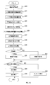
例えば、図11に示すように、第1のノイズ判断用特徴量については、正常範囲R1の幅と、正常範囲R2の幅との差は小さい。両者の幅は同じであってもよい。一方、第2のノイズ判断用特徴量については、正常範囲R1の幅と、正常範囲R2の幅との差は大きい。すなわち、正常範囲R2に比べて、正常範囲R1が広げられている程度は、第1のノイズ判断用特徴量の方が、第2のノイズ判断用特徴量よりも小さい。
例えば、図11に示すように、第1のノイズ判断用特徴量については、正常範囲R1の幅と、正常範囲R2の幅との差は小さい。両者の幅は同じであってもよい。一方、第2のノイズ判断用特徴量については、正常範囲R1の幅と、正常範囲R2の幅との差は大きい。すなわち、正常範囲R2に比べて、正常範囲R1が広げられている程度は、第1のノイズ判断用特徴量の方が、第2のノイズ判断用特徴量よりも小さい。
前記ステップ10において、拍判断ユニット17は、2種以上のノイズ判断用特徴量のそれぞれについて、ノイズ判断用特徴量が、正常範囲内であるか否かを判断する。そして、ある拍における2種以上のノイズ判断用特徴量の全てが正常範囲内である場合、その拍を正常拍と判断する。一方、ある拍における2種以上のノイズ判断用特徴量うち、1つでも正常範囲外である場合、その拍は正常拍ではないと判断する。
3.血圧推定装置1が奏する効果
以上詳述した第3実施形態によれば、前述した第1実施形態の効果に加え、以下の効果が得られる。
以上詳述した第3実施形態によれば、前述した第1実施形態の効果に加え、以下の効果が得られる。
(3A)血圧推定装置1は、脈波信号の1拍ごとに、2種以上のノイズ判断用特徴量を取得する。また、血圧推定装置1は、2種以上のノイズ判断用特徴量のそれぞれについて、正常範囲を設定する。そして、血圧推定装置1は、2種以上のノイズ判断用特徴量がそれぞれ正常範囲内にある拍を正常拍であると判断する。そのことにより、血圧推定装置1は、正常拍であるか否かを一層正確に判断することができる。
(3B)正常範囲R2に比べて、正常範囲R1が広げられている程度は、ノイズ判断用特徴量ごとに異なる。そのことにより、ノイズ判断用特徴量ごとに、正常範囲を適切に設定することができる。その結果、血圧推定装置1は、正常拍であるか否かを一層正確に判断することができる。
(3C)正常範囲R2に比べて、正常範囲R1が広げられている程度は、第1のノイズ判断用特徴量の方が、第2のノイズ判断用特徴量よりも小さい。このことによる効果を以下で説明する。
脈波信号が不整脈に該当する状況において、第1のノイズ判断用特徴量が正常範囲内にあるか否かを判断する場合を想定する。この場合に用いられる正常範囲R1は、正常範囲R2に比べて、あまり広げられていない。そのため、実際にノイズが大きい拍を、「第1のノイズ判断用特徴量が正常範囲内にある」と誤って判断してしまうことを抑制できる。
また、脈波信号が不整脈に該当しても、第1のノイズ判断用特徴量は変動しにくい。そのため、第1のノイズ判断用特徴量に関する判断に用いる正常範囲R1が比較的狭くても、実際にはノイズが小さい拍について、「第1のノイズ判断用特徴量が正常範囲内にない」と誤って判断してしまうことは生じにくい。
<他の実施形態>
以上、本開示を実施するための形態について説明したが、本開示は上述の実施形態に限定されることなく、種々変形して実施することができる。
<他の実施形態>
以上、本開示を実施するための形態について説明したが、本開示は上述の実施形態に限定されることなく、種々変形して実施することができる。
(1)第1、第3実施形態において、前記ステップ10の後、常に前記ステップ13、14の処理を行ってもよい。すなわち、前記ステップ11、12の処理は行わなくてもよい。
(2)第1、第3実施形態における前記ステップ7、第2実施形態における前記ステップ30において、不整脈以外の生体由来の特性を有するか否かを判断してもよい。不整脈以外の生体由来の特性として、例えば、低灌流等が挙げられる。低灌流は、血管狭窄又は心不全に伴う特性である。低灌流は、末梢まで血液が行き渡らない状態である。低灌流であるとき、脈派信号における脈派振幅が大幅に減少する。その結果、脈派信号の信号が弱くなり、ノイズが増大する。
前記ステップ2又は前記ステップ22において、低灌流であるか否かを次のように判断することができる。まず、脈派振幅を継続的に取得する。そして、脈派振幅が予め設定された閾値以下である状態が、予め設定された時間以上継続した場合は、低灌流であると判断し、それ以外の場合は、低灌流ではないと判断することができる。
(3)第2実施形態の前記ステップ34において、正常拍だけではなく、全ての拍を用いて血圧を推定してもよい。
(4)第1、第3の実施形態の前記ステップ7、及び第2実施形態の前記ステップ30において、他の方法で不整脈に該当するか否かを判断してもよい。例えば、前記(a)が充足されれば、不整脈に該当すると判断し、前記(a)が充足されなければ、不整脈に該当しないと判断してもよい。
(4)第1、第3の実施形態の前記ステップ7、及び第2実施形態の前記ステップ30において、他の方法で不整脈に該当するか否かを判断してもよい。例えば、前記(a)が充足されれば、不整脈に該当すると判断し、前記(a)が充足されなければ、不整脈に該当しないと判断してもよい。
(5)PP間隔、及び傾きXのばらつきを表す指標は、上述したもの以外であってもよい。例えば、標準偏差等を、ばらつきを表す指標として用いることができる。
(6)上記実施形態における1つの構成要素が有する複数の機能を、複数の構成要素によって実現したり、1つの構成要素が有する1つの機能を、複数の構成要素によって実現したりしてもよい。また、複数の構成要素が有する複数の機能を、1つの構成要素によって実現したり、複数の構成要素によって実現される1つの機能を、1つの構成要素によって実現したりしてもよい。また、上記実施形態の構成の一部を省略してもよい。また、上記実施形態の構成の少なくとも一部を、他の上記実施形態の構成に対して付加又は置換してもよい。なお、特許請求の範囲に記載した文言のみによって特定される技術思想に含まれるあらゆる態様が本開示の実施形態である。
(6)上記実施形態における1つの構成要素が有する複数の機能を、複数の構成要素によって実現したり、1つの構成要素が有する1つの機能を、複数の構成要素によって実現したりしてもよい。また、複数の構成要素が有する複数の機能を、1つの構成要素によって実現したり、複数の構成要素によって実現される1つの機能を、1つの構成要素によって実現したりしてもよい。また、上記実施形態の構成の一部を省略してもよい。また、上記実施形態の構成の少なくとも一部を、他の上記実施形態の構成に対して付加又は置換してもよい。なお、特許請求の範囲に記載した文言のみによって特定される技術思想に含まれるあらゆる態様が本開示の実施形態である。
(7)上述した血圧推定装置の他、当該血圧推定装置を構成要素とするシステム、制御部3としてコンピュータを機能させるためのプログラム、このプログラムを記録した半導体メモリ等の非遷移的実態的記録媒体、血圧推定方法、不整脈判断方法、ノイズ判断方法等、種々の形態で本開示を実現することもできる。
Claims (7)
- 被験者の脈波信号を取得する脈波信号取得ユニット(13)と、
前記脈波信号の1拍ごとに少なくとも1種の特徴量を取得する特徴量取得ユニット(15)と、
前記脈波信号の1拍ごとに、前記少なくとも1種の特徴量が正常範囲内にある拍であるか否かを判断する拍判断ユニット(17)と、
前記脈波信号のうち、前記拍判断ユニットにより、前記少なくとも1種の特徴量が前記正常範囲内にある拍であると判断された拍を用いて血圧を推定する血圧推定ユニット(19)と、
前記脈波信号が生体由来の特性を有するか否かを判断する特性判断ユニット(21)と、
前記脈波信号が前記特性を有すると前記特性判断ユニットが判断した場合は、前記脈波信号が前記特性を有さないと前記特性判断ユニットが判断した場合よりも、前記正常範囲を広く設定する正常範囲設定ユニット(23)と、
を備える血圧推定装置(1)。 - 請求項1に記載の血圧推定装置であって、
前記特徴量取得ユニットは、前記脈波信号の1拍ごとに、前記少なくとも1種の特徴量として2種以上の特徴量を取得するように構成され、
前記拍判断ユニットは、前記脈波信号の1泊ごとに、前記2種以上の前記特徴量がそれぞれ前記正常範囲内にある拍であるか否かを判断するように構成され、
前記正常範囲設定ユニットは、前記2種以上の前記特徴量のそれぞれについて、前記正常範囲を設定するように構成された血圧推定装置。 - 請求項2に記載の血圧推定装置であって、
前記正常範囲設定ユニットは、前記脈波信号が前記特性を有すると前記特性判断ユニットが判断した場合に前記正常範囲を広げる程度が、前記特徴量ごとに異なるように構成された血圧推定装置。 - 請求項3に記載の血圧推定装置であって、
前記正常範囲設定ユニットは、脈波開始点から第1ピークまでの期間に関する特徴量の方が、前記脈波開始点から第1ピークまでの期間に関する特徴量よりも、前記正常範囲を広げる程度が小さくなるように構成された血圧推定装置。 - 被験者の脈波信号を取得する脈波信号取得ユニット(13)と、
前記脈波信号の1拍ごとに特徴量を取得する特徴量取得ユニット(15)と、
前記脈波信号の1拍ごとに、前記特徴量が正常範囲内にある拍であるか否かを判断する拍判断ユニット(17)と、
前記脈波信号のうち、前記拍判断ユニットにより、前記特徴量が前記正常範囲内にある拍であると判断された拍が占める比率を算出する比率算出ユニット(25)と、
前記比率が閾値以上であることを条件として、前記脈波信号を用いて血圧を推定する血圧推定ユニット(19)と、
前記脈波信号が生体由来の特性を有するか否かを判断する特性判断ユニット(21)と、
前記脈波信号が前記特性を有すると前記特性判断ユニットが判断した場合は、前記脈波信号が前記特性を有さないと前記特性判断ユニットが判断した場合よりも、前記閾値を小さくする閾値設定ユニット(39)と、
を備える血圧推定装置(1)。 - 請求項1~5のいずれか1項に記載の血圧推定装置であって、
前記特性は不整脈であり、
前記特性判断ユニットは、前記脈波信号におけるピーク間隔のばらつきの大きさが予め設定された基準値以上である場合に、前記脈波信号が不整脈に該当すると判断するように構成された血圧推定装置。 - 請求項1~5のいずれか1項に記載の血圧推定装置であって、
前記特性は不整脈であり、
前記特性判断ユニットは、(a)前記脈波信号におけるピーク間隔のばらつきの大きさが予め設定された基準値以上であり、且つ(b)前記脈波信号の各拍における脈波開始点から第1ピークまでの期間に関する特徴量のばらつきの大きさが予め設定された基準値以下である場合に、前記脈波信号が不整脈に該当すると判断するように構成された血圧推定装置。
Applications Claiming Priority (2)
| Application Number | Priority Date | Filing Date | Title |
|---|---|---|---|
| JP2016059856A JP6575409B2 (ja) | 2016-03-24 | 2016-03-24 | 血圧推定装置 |
| JP2016-059856 | 2016-03-24 |
Publications (1)
| Publication Number | Publication Date |
|---|---|
| WO2017164316A1 true WO2017164316A1 (ja) | 2017-09-28 |
Family
ID=59900355
Family Applications (1)
| Application Number | Title | Priority Date | Filing Date |
|---|---|---|---|
| PCT/JP2017/011751 Ceased WO2017164316A1 (ja) | 2016-03-24 | 2017-03-23 | 血圧推定装置 |
Country Status (2)
| Country | Link |
|---|---|
| JP (1) | JP6575409B2 (ja) |
| WO (1) | WO2017164316A1 (ja) |
Cited By (1)
| Publication number | Priority date | Publication date | Assignee | Title |
|---|---|---|---|---|
| CN115770028A (zh) * | 2022-12-16 | 2023-03-10 | 深圳市爱都科技有限公司 | 血压检测方法、系统、装置及存储介质 |
Families Citing this family (1)
| Publication number | Priority date | Publication date | Assignee | Title |
|---|---|---|---|---|
| JP2020025732A (ja) * | 2018-08-10 | 2020-02-20 | 株式会社東芝 | 脈波評価装置及び脈波評価方法 |
Citations (4)
| Publication number | Priority date | Publication date | Assignee | Title |
|---|---|---|---|---|
| JPH04285530A (ja) * | 1991-03-14 | 1992-10-09 | Omron Corp | 波形判別装置 |
| JP2001506167A (ja) * | 1997-06-06 | 2001-05-15 | サウスウエスト・リサーチ・インスティテュート | 生体の心臓血管状態を精度よく監視するシステムと方法 |
| JP2009125531A (ja) * | 2007-11-28 | 2009-06-11 | Nippon Koden Corp | 血圧測定装置 |
| JP2012045304A (ja) * | 2010-08-30 | 2012-03-08 | Denso Corp | 血圧推定装置 |
Family Cites Families (3)
| Publication number | Priority date | Publication date | Assignee | Title |
|---|---|---|---|---|
| JP2003047601A (ja) * | 2001-05-31 | 2003-02-18 | Denso Corp | 生体異常監視装置、血圧監視装置、生体異常監視方法、及び血圧監視方法 |
| JP6020082B2 (ja) * | 2012-11-19 | 2016-11-02 | Tdk株式会社 | 生体信号計測装置、生体信号計測方法及び生体信号計測プログラム |
| JP6032165B2 (ja) * | 2013-09-18 | 2016-11-24 | 株式会社デンソー | 血圧計 |
-
2016
- 2016-03-24 JP JP2016059856A patent/JP6575409B2/ja not_active Expired - Fee Related
-
2017
- 2017-03-23 WO PCT/JP2017/011751 patent/WO2017164316A1/ja not_active Ceased
Patent Citations (4)
| Publication number | Priority date | Publication date | Assignee | Title |
|---|---|---|---|---|
| JPH04285530A (ja) * | 1991-03-14 | 1992-10-09 | Omron Corp | 波形判別装置 |
| JP2001506167A (ja) * | 1997-06-06 | 2001-05-15 | サウスウエスト・リサーチ・インスティテュート | 生体の心臓血管状態を精度よく監視するシステムと方法 |
| JP2009125531A (ja) * | 2007-11-28 | 2009-06-11 | Nippon Koden Corp | 血圧測定装置 |
| JP2012045304A (ja) * | 2010-08-30 | 2012-03-08 | Denso Corp | 血圧推定装置 |
Cited By (1)
| Publication number | Priority date | Publication date | Assignee | Title |
|---|---|---|---|---|
| CN115770028A (zh) * | 2022-12-16 | 2023-03-10 | 深圳市爱都科技有限公司 | 血压检测方法、系统、装置及存储介质 |
Also Published As
| Publication number | Publication date |
|---|---|
| JP2017169880A (ja) | 2017-09-28 |
| JP6575409B2 (ja) | 2019-09-18 |
Similar Documents
| Publication | Publication Date | Title |
|---|---|---|
| JP4855721B2 (ja) | 血圧測定装置 | |
| US20160287107A1 (en) | Intelligent photoplethysmograph signal-to-noise ratio control for recovery of biosignals during times of motion | |
| JP6680155B2 (ja) | 血圧測定装置、血圧測定装置の制御方法およびプログラム | |
| CN112515629B (zh) | 用于估计生物信息的设备 | |
| JP6652655B2 (ja) | 心拍検出方法および心拍検出装置 | |
| KR20200112095A (ko) | 혈압을 측정하는 전자 장치 및 혈압 측정 방법 | |
| EP3878352B1 (en) | Apparatus and method for estimating bio-information | |
| JP5760876B2 (ja) | 心房細動判定装置、心房細動判定方法およびプログラム | |
| JP6418131B2 (ja) | 脈波信号処理装置 | |
| JP2017023472A (ja) | 生体情報推定装置、生体情報推定方法、及びコンピュータプログラム | |
| US11844631B2 (en) | Apparatus and method for estimating bio-information | |
| JP2001198094A (ja) | 脈拍数検出装置 | |
| JP6575409B2 (ja) | 血圧推定装置 | |
| JP6656005B2 (ja) | 血圧計 | |
| KR20090081885A (ko) | 심박 검출장치 및 그 제어방법 | |
| KR102709502B1 (ko) | 자율적 전체 스펙트럼 생체 인식 모니터링 | |
| JP2022160608A (ja) | 生体信号処理装置およびその制御方法 | |
| CN113143202B (zh) | 用于估计生物信息的设备 | |
| CN114376545B (zh) | 用于估计生物信息的设备和方法 | |
| JP5998516B2 (ja) | 拍動検出装置、電子機器及びプログラム | |
| JP2019209042A (ja) | 信号計測方法 | |
| JP6519487B2 (ja) | 脈波解析装置 | |
| JP2019209041A (ja) | 脈波形解析方法、及びプログラム | |
| JP6859489B2 (ja) | 運動強度推定方法、運動強度推定装置およびプログラム | |
| CN115105033B (zh) | 用于估计生物信息的设备和方法 |
Legal Events
| Date | Code | Title | Description |
|---|---|---|---|
| NENP | Non-entry into the national phase |
Ref country code: DE |
|
| 121 | Ep: the epo has been informed by wipo that ep was designated in this application |
Ref document number: 17770356 Country of ref document: EP Kind code of ref document: A1 |
|
| 122 | Ep: pct application non-entry in european phase |
Ref document number: 17770356 Country of ref document: EP Kind code of ref document: A1 |