WO2017164258A1 - タービンの支持構造 - Google Patents
タービンの支持構造 Download PDFInfo
- Publication number
- WO2017164258A1 WO2017164258A1 PCT/JP2017/011546 JP2017011546W WO2017164258A1 WO 2017164258 A1 WO2017164258 A1 WO 2017164258A1 JP 2017011546 W JP2017011546 W JP 2017011546W WO 2017164258 A1 WO2017164258 A1 WO 2017164258A1
- Authority
- WO
- WIPO (PCT)
- Prior art keywords
- shroud
- turbine
- nozzle
- outer peripheral
- peripheral flange
- Prior art date
- Legal status (The legal status is an assumption and is not a legal conclusion. Google has not performed a legal analysis and makes no representation as to the accuracy of the status listed.)
- Ceased
Links
Images


Classifications
-
- F—MECHANICAL ENGINEERING; LIGHTING; HEATING; WEAPONS; BLASTING
- F01—MACHINES OR ENGINES IN GENERAL; ENGINE PLANTS IN GENERAL; STEAM ENGINES
- F01D—NON-POSITIVE DISPLACEMENT MACHINES OR ENGINES, e.g. STEAM TURBINES
- F01D25/00—Component parts, details, or accessories, not provided for in, or of interest apart from, other groups
- F01D25/24—Casings; Casing parts, e.g. diaphragms, casing fastenings
- F01D25/246—Fastening of diaphragms or stator-rings
-
- F—MECHANICAL ENGINEERING; LIGHTING; HEATING; WEAPONS; BLASTING
- F01—MACHINES OR ENGINES IN GENERAL; ENGINE PLANTS IN GENERAL; STEAM ENGINES
- F01D—NON-POSITIVE DISPLACEMENT MACHINES OR ENGINES, e.g. STEAM TURBINES
- F01D25/00—Component parts, details, or accessories, not provided for in, or of interest apart from, other groups
- F01D25/24—Casings; Casing parts, e.g. diaphragms, casing fastenings
-
- F—MECHANICAL ENGINEERING; LIGHTING; HEATING; WEAPONS; BLASTING
- F01—MACHINES OR ENGINES IN GENERAL; ENGINE PLANTS IN GENERAL; STEAM ENGINES
- F01D—NON-POSITIVE DISPLACEMENT MACHINES OR ENGINES, e.g. STEAM TURBINES
- F01D11/00—Preventing or minimising internal leakage of working-fluid, e.g. between stages
- F01D11/08—Preventing or minimising internal leakage of working-fluid, e.g. between stages for sealing space between rotor blade tips and stator
-
- F—MECHANICAL ENGINEERING; LIGHTING; HEATING; WEAPONS; BLASTING
- F01—MACHINES OR ENGINES IN GENERAL; ENGINE PLANTS IN GENERAL; STEAM ENGINES
- F01D—NON-POSITIVE DISPLACEMENT MACHINES OR ENGINES, e.g. STEAM TURBINES
- F01D25/00—Component parts, details, or accessories, not provided for in, or of interest apart from, other groups
- F01D25/24—Casings; Casing parts, e.g. diaphragms, casing fastenings
- F01D25/243—Flange connections; Bolting arrangements
-
- F—MECHANICAL ENGINEERING; LIGHTING; HEATING; WEAPONS; BLASTING
- F01—MACHINES OR ENGINES IN GENERAL; ENGINE PLANTS IN GENERAL; STEAM ENGINES
- F01D—NON-POSITIVE DISPLACEMENT MACHINES OR ENGINES, e.g. STEAM TURBINES
- F01D9/00—Stators
- F01D9/02—Nozzles; Nozzle boxes; Stator blades; Guide conduits, e.g. individual nozzles
-
- F—MECHANICAL ENGINEERING; LIGHTING; HEATING; WEAPONS; BLASTING
- F01—MACHINES OR ENGINES IN GENERAL; ENGINE PLANTS IN GENERAL; STEAM ENGINES
- F01D—NON-POSITIVE DISPLACEMENT MACHINES OR ENGINES, e.g. STEAM TURBINES
- F01D9/00—Stators
- F01D9/02—Nozzles; Nozzle boxes; Stator blades; Guide conduits, e.g. individual nozzles
- F01D9/04—Nozzles; Nozzle boxes; Stator blades; Guide conduits, e.g. individual nozzles forming ring or sector
-
- F—MECHANICAL ENGINEERING; LIGHTING; HEATING; WEAPONS; BLASTING
- F01—MACHINES OR ENGINES IN GENERAL; ENGINE PLANTS IN GENERAL; STEAM ENGINES
- F01D—NON-POSITIVE DISPLACEMENT MACHINES OR ENGINES, e.g. STEAM TURBINES
- F01D9/00—Stators
- F01D9/02—Nozzles; Nozzle boxes; Stator blades; Guide conduits, e.g. individual nozzles
- F01D9/04—Nozzles; Nozzle boxes; Stator blades; Guide conduits, e.g. individual nozzles forming ring or sector
- F01D9/041—Nozzles; Nozzle boxes; Stator blades; Guide conduits, e.g. individual nozzles forming ring or sector using blades
-
- F—MECHANICAL ENGINEERING; LIGHTING; HEATING; WEAPONS; BLASTING
- F02—COMBUSTION ENGINES; HOT-GAS OR COMBUSTION-PRODUCT ENGINE PLANTS
- F02C—GAS-TURBINE PLANTS; AIR INTAKES FOR JET-PROPULSION PLANTS; CONTROLLING FUEL SUPPLY IN AIR-BREATHING JET-PROPULSION PLANTS
- F02C7/00—Features, components parts, details or accessories, not provided for in, or of interest apart form groups F02C1/00 - F02C6/00; Air intakes for jet-propulsion plants
-
- F—MECHANICAL ENGINEERING; LIGHTING; HEATING; WEAPONS; BLASTING
- F05—INDEXING SCHEMES RELATING TO ENGINES OR PUMPS IN VARIOUS SUBCLASSES OF CLASSES F01-F04
- F05D—INDEXING SCHEME FOR ASPECTS RELATING TO NON-POSITIVE-DISPLACEMENT MACHINES OR ENGINES, GAS-TURBINES OR JET-PROPULSION PLANTS
- F05D2240/00—Components
- F05D2240/10—Stators
- F05D2240/11—Shroud seal segments
-
- F—MECHANICAL ENGINEERING; LIGHTING; HEATING; WEAPONS; BLASTING
- F05—INDEXING SCHEMES RELATING TO ENGINES OR PUMPS IN VARIOUS SUBCLASSES OF CLASSES F01-F04
- F05D—INDEXING SCHEME FOR ASPECTS RELATING TO NON-POSITIVE-DISPLACEMENT MACHINES OR ENGINES, GAS-TURBINES OR JET-PROPULSION PLANTS
- F05D2240/00—Components
- F05D2240/10—Stators
- F05D2240/12—Fluid guiding means, e.g. vanes
- F05D2240/128—Nozzles
-
- F—MECHANICAL ENGINEERING; LIGHTING; HEATING; WEAPONS; BLASTING
- F05—INDEXING SCHEMES RELATING TO ENGINES OR PUMPS IN VARIOUS SUBCLASSES OF CLASSES F01-F04
- F05D—INDEXING SCHEME FOR ASPECTS RELATING TO NON-POSITIVE-DISPLACEMENT MACHINES OR ENGINES, GAS-TURBINES OR JET-PROPULSION PLANTS
- F05D2240/00—Components
- F05D2240/10—Stators
- F05D2240/14—Casings or housings protecting or supporting assemblies within
-
- F—MECHANICAL ENGINEERING; LIGHTING; HEATING; WEAPONS; BLASTING
- F05—INDEXING SCHEMES RELATING TO ENGINES OR PUMPS IN VARIOUS SUBCLASSES OF CLASSES F01-F04
- F05D—INDEXING SCHEME FOR ASPECTS RELATING TO NON-POSITIVE-DISPLACEMENT MACHINES OR ENGINES, GAS-TURBINES OR JET-PROPULSION PLANTS
- F05D2260/00—Function
- F05D2260/30—Retaining components in desired mutual position
Definitions
- the present invention relates to a structure for supporting a nozzle and a shroud constituting a turbine by a turbine casing covering an outer periphery of the turbine in a turbine of a gas turbine engine.
- An object of the present invention is to provide a turbine support structure capable of reliably supporting a nozzle and a shroud while reducing the number of parts and the number of assembling steps in order to solve the above-described problems.
- a turbine support structure includes: In a turbine of a gas turbine engine, a turbine casing covering an outer periphery of the turbine is configured to support a plurality of nozzles constituting the turbine and a shroud facing a moving blade adjacent to the nozzles, The front end portion and the rear end portion of the outer peripheral flange of each nozzle are respectively engaged with the inner peripheral portion of the turbine casing, A front end portion of the shroud is engaged with a rear end portion of the outer peripheral flange located in front of the shroud, and a rear end portion of the shroud is engaged with a front end portion of the outer peripheral flange located behind the shroud.
- the support pin is provided at an engaging portion on a front end side of the outer peripheral flange, and an axial force applied to the outer peripheral flange is applied to the turbine casing behind the outer peripheral flange.
- a thrust ring that transmits to the lens may be disposed. According to this configuration, by providing the thrust ring, it is avoided that a large axial force applied to the nozzle engaging portion of the outer peripheral flange is further applied to the shroud positioned behind the thrust engaging member. It becomes possible to support stably. In addition, it is possible to arrange the support pins and the thrust ring while keeping the positional relationship between the nozzle and the shroud appropriately.
- the nozzle is composed of a plurality of nozzle division bodies divided in the circumferential direction, and the shroud is divided in the circumferential direction, which is twice as many as the nozzle division bodies.
- the plurality of support pins are respectively inserted into a central insertion groove formed in a circumferential central portion of the outer peripheral flange division body of the nozzle division body and an end insertion groove formed in both end portions, A gap is formed between the end insertion groove and the support pin inserted into the end insertion groove in a state where the outer peripheral flange divided body is positioned in the circumferential direction by the support pin inserted through the central insertion groove. It may be. According to this configuration, it is possible to reduce the circumferential dimension of the shroud divided body to suppress the amount of thermal elongation, and to avoid over-constraining the thermal expansion of the nozzle divided body.
- FIG. 1 is a side view in which a part of a gas turbine engine (hereinafter simply referred to as a gas turbine) GE having a turbine support structure according to an embodiment of the present invention is broken.
- the gas turbine GE compresses the air A introduced from the outside with the compressor 1 and guides it to the combustor 3.
- the fuel F is burned together with the compressed air CA in the combustor 3, and the obtained high-temperature and high-pressure combustion gas G is used.
- the turbine 5 is driven.
- a plurality of can-type combustors 3 are arranged at equal intervals along the circumferential direction of the gas turbine GE.
- the compressor 1 side in the direction of the axis C of the gas turbine GE may be referred to as “front” and the turbine 5 side may be referred to as “rear”.
- “Before” and “after” attached to the names of elements constituting the embodiment have the same meaning.
- “axial direction”, “circumferential direction”, and “radial direction” mean the axial C direction, circumferential direction, and radial direction of the gas turbine GE, unless otherwise specified.
- the high-temperature and high-pressure combustion gas G generated in the combustor 3 flows into the turbine 5 from the first stage nozzle (first stage stationary blade) 11 of the turbine 5.
- a plurality of nozzles (stationary blades) 13 and a plurality of rotor blades 17 arranged on the outer peripheral surface of the rotor R that constitutes a rotating portion of the gas turbine GE are axially arranged. Are alternately arranged adjacent to each other.
- a conical surface outer peripheral flange 19 is provided on the outer peripheral portion of each nozzle 13.
- each rotor blade 17 is covered with a shroud 21 on the outer side in the radial direction.
- the shroud 21 is opposed to the end portion of each blade 17 while being spaced apart in the radial direction.
- the shroud 21 and the outer peripheral flange 19 are arranged alternately in the axial direction and in contact with each other.
- the nozzle 13 and the shroud 21 are supported by the turbine casing 23 that covers the outer periphery of the turbine 5.
- the shroud 21 disposed to face the n-th stage moving blade 17 n may be referred to as “n-th stage shroud 21 n ”.
- the structure in which the nozzle 13 and the shroud 21 are supported by the turbine casing 23 will be described in detail later.
- the first stage nozzle 11 of the turbine 5 is supported by the housing H of the gas turbine GE via the first stage nozzle support 25 that covers the outer periphery thereof.
- the first stage nozzle support 25 which is formed separately, the rear turbine section than the first stage nozzle 11 and covers the outer periphery of the rear turbine section that is from the first stage moving blades 17 1
- the casing member is referred to as “turbine casing 23”.
- nozzle 13 is excluding the first stage nozzle 11, an example nozzle (shown than the first stage moving blades 17 1 disposed behind Then, the second stage nozzle and the third stage nozzle) 13 are indicated.
- the turbine casing 23 is not a split type divided into two in the circumferential direction, but is a single piece. Accordingly, the nozzle 13, the moving blade 17, the shroud 21, and the like are incorporated into the turbine casing 23 from behind.
- the turbine casing 23 includes a casing main body portion 23a that is a portion that covers the outer periphery of the turbine 5, and a cylindrical connecting portion 23b that extends rearward from the casing main body portion 23a.
- the casing body 23a that covers the outer periphery of the turbine 5 has a shape that increases in diameter toward the rear.
- a rear end flange 27 projecting radially outward is provided at the rearmost end of the connecting portion 23b.
- the turbine casing 23 is connected to the rear end portion Ha of the gas turbine GE housing H by a connecting member such as a connecting pin P1 through the rear end flange 27, and is positioned in the rear end portion Ha and the rear duct. 31 is supported.
- the rear duct 31 is connected to the rear end Ha by a bolt (not shown).
- the housing H and the rear duct 31 are positioned by a connecting pin P2.
- the support structure according to the present embodiment includes, among the plurality of nozzles 13 and the plurality of shrouds 21 illustrated in FIG. 3, in particular, a shroud 21 (second-stage shroud in the illustrated example) disposed between the two nozzles 13 and 13. 21 2 ) and the two nozzles 13 and 13 respectively disposed on the front and rear ends of the shroud 21.
- a shroud 21 second-stage shroud in the illustrated example
- the shroud 21 supporting structure according to the present embodiment is applied is only two second-stage shroud 21, the number of the number and the shroud 21 of the nozzle 13 may be greater than the illustrated example In that case, the support structure according to the present embodiment can be applied to the plurality of shrouds 21.
- a nozzle engaging portion 41 protrudes from the outer peripheral flange 19 of the nozzle 13.
- the shroud 21 has a shroud engaging portion 43 protruding therefrom.
- a casing engaging portion 45 that engages with the nozzle engaging portion 41 is provided on the inner peripheral portion of the turbine casing 23 in a protruding manner.
- a plurality (two in this example) of casing engaging portions 45 of the turbine casing 23 are formed at different axial positions.
- the front engaging portion may be referred to as a front casing engaging portion 45F
- the rear engaging portion may be referred to as a rear casing engaging portion 45R.
- a front nozzle engaging portion 41 ⁇ / b> F made of a protruding piece protruding forward is provided at the front end portion of the outer peripheral flange 19 of the nozzle 13.
- a rear nozzle engaging portion 41R made of a protruding piece is provided.
- the front end of the second stage shroud 21 2 is provided with a front shroud engaging portion 43F consisting projecting piece projecting forward, the rear end portion of the second stage shroud 21 2, rearwardly projecting end collision
- a rear shroud engaging portion 43R made of a piece is provided.
- the nozzle engaged portion 47 serving as the engaged portion with which the shroud engaging portion 43 of the shroud 21 is engaged is formed on the outer peripheral flange 19.
- a front nozzle engaged portion 47 ⁇ / b> F consisting of a recess recessed backward is provided at the front end portion of the outer peripheral flange 19, and the rear end portion of the outer peripheral flange 19 is provided.
- a rear nozzle engaged portion 47R made of a recess recessed forward is provided.
- a front end flange portion 19a protruding outward in the radial direction is provided at a portion slightly rearward from the front end surface of the outer peripheral flange 19 over the entire circumference, and the front nozzle engagement portion 41F has a front end flange portion. It protrudes forward from the outer edge of the portion 19a. A recess between the front end portion of the outer peripheral flange 19 and the front nozzle engaging portion 41F forms the front nozzle engaged portion 47F.
- a rear end flange portion 19b protruding outward in the radial direction is provided over the entire circumference at a position slightly forward from the rear end face of the outer peripheral flange 19.
- the rear nozzle engaging portion 41R of the outer peripheral flange 19 protrudes forward from the outer edge of the rear end flange portion 19b.
- the rear nozzle engaged portion 47 ⁇ / b> R is formed as a recess that is recessed forward from the rear end surface of the outer peripheral flange 19.
- the turbine casing 23 having such a structure, the outer peripheral flange 19 of the nozzle 13 and the shroud 21 are engaged as follows.
- a casing engaging portion 45 (a front end portion (front nozzle engaging portion 41F) and a rear end portion (rear nozzle engaging portion 41R) of the outer peripheral flange 19 of the nozzle 13 are formed on the inner peripheral portion of the turbine casing 23, respectively.
- the front casing engaging portion 45F and the rear casing engaging portion 45R) are engaged.
- front end portion (front shroud engaging portion 43F) of the shroud 21 is engaged with the rear end portion (rear nozzle engaged portion 47R) of the outer peripheral flange 19 positioned in front of the shroud 21, and the shroud 21
- rear end portion (rear shroud engaging portion 43R) is engaged with the front end portion (front nozzle engaged portion 47F) of the outer peripheral flange 19 located behind the shroud 21.
- 41 and the shroud engagement part 43 of the shroud 21 are formed with overlapping engagement portions 49 that overlap each other in the radial direction.
- the overlapping engagement portion is formed by the members engaged at the front end portion of the rear outer peripheral flange 19, that is, the front nozzle engagement portion 41F, the rear casing engagement portion 45R, and the rear shroud engagement portion 43R. 49 is formed.
- a common support pin 51 passes through the overlapping engagement portion 49 in the radial direction.
- a plurality of support pins 51 are provided in the circumferential direction.
- the nozzle 13 and the shroud 21 are positioned and supported with respect to the turbine casing 23 in the circumferential direction by the support pins 51.
- the number of parts can be reduced.
- the shape of each engaging part and to-be-engaged part is not limited to the example of illustration.
- An annular thrust ring 55 is disposed behind the rear nozzle engaging portion 41R of the outer peripheral flange 19.
- the thrust ring 55 is formed in a substantially L-shaped cross section.
- a fitting groove 57 that is recessed radially outward is formed on the inner peripheral surface of the turbine casing 23, and the thrust ring 55 is fitted in the fitting groove 57.
- the thrust ring 55 having a substantially L-shaped cross section has an annular protrusion 55 a protruding outward in the radial direction, and the annular protrusion 55 a is fitted in the fitting groove 57. .
- a front wall surface (a wall surface facing rearward) 57a of the fitting groove 57 is a rear end surface (that is, an outer peripheral surface) of the rear end flange portion 19b of the outer peripheral flange 19 in a state where the outer peripheral flange 19 is engaged with the casing engaging portion 45.
- the rear nozzle engagement portion 41R of the flange 19 is formed at a position substantially aligned with the rear end surface 19ba. Therefore, the axial force applied to the rear nozzle engaging portion 41 ⁇ / b> R is transmitted to the turbine casing 23 (more specifically, the wall surface 57 b behind the fitting groove 57) via the thrust ring 55.
- the thrust ring 55 may be omitted, by providing the thrust ring 55, a large axial force applied to the nozzle engaging portion 41 of the outer peripheral flange 19 is further applied to the shroud 21 adjacent to the rear thereof. Thus, these members can be stably supported by the turbine casing 23. Moreover, the support pin 51 and the thrust ring 55 are disposed while the positional relationship between the nozzle 13 and the shroud 21 is appropriately maintained by disposing the support pin 51 on the front nozzle engaging portion 41F on the front end side of the outer peripheral flange 19. It becomes possible.
- the thrust ring 55 is disposed in contact with the outer peripheral surface of the front shroud engaging portion 43 ⁇ / b > F of the second stage shroud 212. Thereby, the thrust ring 55 can be stably arranged using the shroud 21 engaged with the outer peripheral flange 19.
- the thrust ring 55 according to the present embodiment is formed as a snap ring, and is fitted into the fitting groove 57 in a state of being reduced in diameter.
- the nozzle 13 is composed of a plurality of nozzle division bodies 13A divided in the circumferential direction.
- An outer peripheral flange divided body 19A obtained by dividing the outer peripheral flange 19 in the circumferential direction is formed on the outer peripheral portion of each nozzle divided body 13A.
- the shroud 21 is composed of a plurality of shroud division bodies 21A divided in the circumferential direction.
- the number of shroud division bodies 21A arranged in the circumferential direction is twice the number of nozzle division bodies 13A.
- the circumferential dimension of the shroud segment 21A is about 1 ⁇ 2 of the circumferential dimension of the outer peripheral flange segment 19A of the nozzle segment 13A.
- the number of shroud divided bodies 21A arranged in the circumferential direction is 24, and the number of nozzle divided bodies 13A is 12. Note that gaps for absorbing thermal elongation are set in advance between the adjacent shroud segments 21A and between the adjacent outer peripheral flange segments 19A.
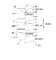
- the plurality of shroud segments 21A are arranged as follows with reference to the circumferential position of the outer flange segment 19A. That is, the plurality of shroud divided bodies 21A have a shroud divided body 21A whose circumferential center position matches the circumferential center position of the outer peripheral flange divided body 19A, and a shroud divided body 21A that matches between adjacent outer peripheral flange divided bodies 19A. Are arranged alternately.
- a shroud insertion groove 61 having an arc-shaped cross section with an inner diameter substantially corresponding to the outer diameter of the support pin 51 is formed on the side portion of each shroud divided body 21A.
- a nozzle center insertion groove 63 positioned at the center in the circumferential direction and nozzle end insertion grooves 65 positioned at both ends in the circumferential direction are formed on the side of each outer peripheral flange divided body 19A.
- the nozzle center insertion groove 63 of the outer peripheral flange divided body 19 ⁇ / b> A is formed as a groove having an arc-shaped cross section having an inner diameter substantially corresponding to the outer diameter of the support pin 51.
- the nozzle end insertion groove 65 is formed as a groove having an arc-shaped cross section having an inner diameter larger than the outer diameter of the support pin 51. Therefore, the nozzle end portion insertion groove 65 and the support inserted into the nozzle end portion insertion groove 65 in a state where the outer peripheral flange divided body 19A is positioned in the circumferential direction by the support pin 51 inserted through the nozzle center insertion groove 63. A gap is formed between the pin 51 and the pin 51.
- each shroud divided body 21A is reliably positioned in the circumferential direction while avoiding over-constraining against thermal expansion by one support pin 51 and a shroud insertion groove 61 with no gap therebetween.
- the peripheral flange divided body 19A of each nozzle is also reliably positioned in the circumferential direction by one support pin 51 and the nozzle center insertion groove 63 without a gap, while being supported at both ends in the circumferential direction.
- the nozzle 13 and the shroud 21 itself are used, and a common support pin is used for a plurality of members to connect these members to the turbine. Since it is supported by the casing 23, it is possible to greatly reduce the number of parts and the number of assembly steps of the turbine 5.
Landscapes
- Engineering & Computer Science (AREA)
- Mechanical Engineering (AREA)
- General Engineering & Computer Science (AREA)
- Chemical & Material Sciences (AREA)
- Combustion & Propulsion (AREA)
- Turbine Rotor Nozzle Sealing (AREA)
Abstract
Description
ガスタービンエンジンのタービンにおいて、当該タービンの外周を覆うタービンケーシングによって、タービンを構成する複数のノズル、およびノズルに隣接する動翼に対向するシュラウドを支持する構造であって、
各ノズルの外周フランジの前端部および後端部が、それぞれ、前記タービンケーシングの内周部に係合しており、
前記シュラウドの前端部が、当該シュラウドの前方に位置する前記外周フランジの後端部に係合しており、前記シュラウドの後端部が、当該シュラウドの後方に位置する前記外周フランジの前端部に係合しており、
前記外周フランジの前端部および後端部のいずれか一方のみにおいて、前記タービンケーシングの係合部と、前記外周フランジの係合部と、前記シュラウドの係合部とが互いに径方向に重なる重畳係合部分が形成されており、
前記重畳係合部分を径方向に貫通する支持ピンによって、前記ノズルおよび前記シュラウドが前記タービンケーシングに支持されている。
13 ノズル
17 動翼
19 ノズルの外周フランジ
21 シュラウド
23 タービンケーシング
41 ノズル係合部
43 シュラウド係合部
45 ケーシング係合部
49 重畳係合部分
51 支持ピン
55 スラストリング
GE ガスタービンエンジン
Claims (3)
- ガスタービンエンジンのタービンにおいて、当該タービンの外周を覆うタービンケーシングによって、タービンを構成する複数のノズル、およびノズルに隣接する動翼に対向するシュラウドを支持する構造であって、
各ノズルの外周フランジの前端部および後端部が、それぞれ、前記タービンケーシングの内周部に係合しており、
前記シュラウドの前端部が、当該シュラウドの前方に位置する前記外周フランジの後端部に係合しており、前記シュラウドの後端部が、当該シュラウドの後方に位置する前記外周フランジの前端部に係合しており、
前記外周フランジの前端部および後端部のいずれか一方のみにおいて、前記タービンケーシングの係合部と、前記外周フランジの係合部と、前記シュラウドの係合部とが互いに径方向に重なる重畳係合部分が形成されており、
前記重畳係合部分を径方向に貫通する支持ピンによって、前記ノズルおよび前記シュラウドが前記タービンケーシングに支持されている、
タービンの支持構造。 - 請求項1に記載の支持構造において、前記支持ピンが、前記外周フランジの前端側の係合部に設けられており、前記外周フランジの後方に、この外周フランジに付加される軸方向力を前記タービンケーシングに伝達するスラストリングが配置されているタービンの支持構造。
- 請求項1または2に記載の支持構造において、
前記ノズルが、周方向に分割された複数のノズル分割体からなり、
前記シュラウドが、周方向に分割された、前記ノズル分割体の2倍の数のシュラウド分割体からなり、
複数の前記支持ピンが、前記ノズル分割体の外周フランジ分割体の周方向中央部に形成された中央挿通溝および両端部に形成された端部挿通溝にそれぞれ挿通されており、
前記外周フランジ分割体が前記中央挿通溝に挿通された支持ピンによって周方向に位置決めされた状態で、前記端部挿通溝と、この端部挿通溝に挿通された支持ピンとの間に隙間が形成されている
タービンの支持構造。
Priority Applications (4)
| Application Number | Priority Date | Filing Date | Title |
|---|---|---|---|
| GB1817149.6A GB2564065B (en) | 2016-03-24 | 2017-03-22 | Turbine support structure |
| DE112017001487.5T DE112017001487B4 (de) | 2016-03-24 | 2017-03-22 | Turbinenhaltestruktur |
| CN201780018915.7A CN108884719B (zh) | 2016-03-24 | 2017-03-22 | 涡轮的支撑结构 |
| US16/137,933 US10968776B2 (en) | 2016-03-24 | 2018-09-21 | Turbine support structure |
Applications Claiming Priority (2)
| Application Number | Priority Date | Filing Date | Title |
|---|---|---|---|
| JP2016060306A JP6612161B2 (ja) | 2016-03-24 | 2016-03-24 | タービンの支持構造 |
| JP2016-060306 | 2016-03-24 |
Related Child Applications (1)
| Application Number | Title | Priority Date | Filing Date |
|---|---|---|---|
| US16/137,933 Continuation US10968776B2 (en) | 2016-03-24 | 2018-09-21 | Turbine support structure |
Publications (1)
| Publication Number | Publication Date |
|---|---|
| WO2017164258A1 true WO2017164258A1 (ja) | 2017-09-28 |
Family
ID=59900262
Family Applications (1)
| Application Number | Title | Priority Date | Filing Date |
|---|---|---|---|
| PCT/JP2017/011546 Ceased WO2017164258A1 (ja) | 2016-03-24 | 2017-03-22 | タービンの支持構造 |
Country Status (6)
| Country | Link |
|---|---|
| US (1) | US10968776B2 (ja) |
| JP (1) | JP6612161B2 (ja) |
| CN (1) | CN108884719B (ja) |
| DE (1) | DE112017001487B4 (ja) |
| GB (2) | GB2564065B (ja) |
| WO (1) | WO2017164258A1 (ja) |
Cited By (1)
| Publication number | Priority date | Publication date | Assignee | Title |
|---|---|---|---|---|
| CN107740711A (zh) * | 2017-12-04 | 2018-02-27 | 贵州智慧能源科技有限公司 | 涡轮轮罩 |
Families Citing this family (1)
| Publication number | Priority date | Publication date | Assignee | Title |
|---|---|---|---|---|
| EP3286410B1 (en) * | 2015-04-24 | 2021-06-02 | Nuovo Pignone Tecnologie Srl | Gas turbine engine having a casing provided with cooling fins |
Citations (7)
| Publication number | Priority date | Publication date | Assignee | Title |
|---|---|---|---|---|
| US3319930A (en) * | 1961-12-19 | 1967-05-16 | Gen Electric | Stator assembly for turbomachines |
| US5232340A (en) * | 1992-09-28 | 1993-08-03 | General Electric Company | Gas turbine engine stator assembly |
| JPH06129205A (ja) * | 1992-10-20 | 1994-05-10 | Mitsubishi Heavy Ind Ltd | ガスタービンの静翼 |
| US6062813A (en) * | 1996-11-23 | 2000-05-16 | Rolls-Royce Plc | Bladed rotor and surround assembly |
| FR2832179A1 (fr) * | 2001-11-14 | 2003-05-16 | Snecma Moteurs | Stator d'une machine et procedes de montage et demontage |
| JP2006112374A (ja) * | 2004-10-18 | 2006-04-27 | Hitachi Ltd | ガスタービン設備 |
| FR3009739A1 (fr) * | 2013-08-13 | 2015-02-20 | Snecma | Amelioration pour le verrouillage de pieces de support d'aubage |
Family Cites Families (11)
| Publication number | Priority date | Publication date | Assignee | Title |
|---|---|---|---|---|
| US4485620A (en) * | 1982-03-03 | 1984-12-04 | United Technologies Corporation | Coolable stator assembly for a gas turbine engine |
| GB2249356B (en) * | 1990-11-01 | 1995-01-18 | Rolls Royce Plc | Shroud liners |
| US5618161A (en) * | 1995-10-17 | 1997-04-08 | Westinghouse Electric Corporation | Apparatus for restraining motion of a turbo-machine stationary vane |
| JP3034519B1 (ja) | 1999-04-15 | 2000-04-17 | 川崎重工業株式会社 | タ―ビンロ―タの冷却構造を改善したガスタ―ビン |
| JP4269763B2 (ja) | 2003-04-28 | 2009-05-27 | 株式会社Ihi | タービンノズルセグメント |
| RU2335637C2 (ru) * | 2003-05-07 | 2008-10-10 | Снекма Мотер | Статор турбомашины и способы его сборки и разборки |
| US8985944B2 (en) * | 2011-03-30 | 2015-03-24 | General Electric Company | Continuous ring composite turbine shroud |
| JP6082193B2 (ja) * | 2012-06-20 | 2017-02-15 | 株式会社Ihi | 翼の連結部構造及びこれを用いたジェットエンジン |
| JP5962915B2 (ja) * | 2012-10-29 | 2016-08-03 | 株式会社Ihi | タービンノズルの固定部構造及びこれを用いたタービン |
| JP5889266B2 (ja) * | 2013-11-14 | 2016-03-22 | 三菱重工業株式会社 | タービン |
| JP2016060306A (ja) | 2014-09-17 | 2016-04-25 | 株式会社ケーヒン | 車両用空調装置 |
-
2016
- 2016-03-24 JP JP2016060306A patent/JP6612161B2/ja active Active
-
2017
- 2017-03-22 WO PCT/JP2017/011546 patent/WO2017164258A1/ja not_active Ceased
- 2017-03-22 GB GB1817149.6A patent/GB2564065B/en active Active
- 2017-03-22 DE DE112017001487.5T patent/DE112017001487B4/de active Active
- 2017-03-22 CN CN201780018915.7A patent/CN108884719B/zh active Active
- 2017-03-22 GB GB2107293.9A patent/GB2591969B/en active Active
-
2018
- 2018-09-21 US US16/137,933 patent/US10968776B2/en active Active
Patent Citations (7)
| Publication number | Priority date | Publication date | Assignee | Title |
|---|---|---|---|---|
| US3319930A (en) * | 1961-12-19 | 1967-05-16 | Gen Electric | Stator assembly for turbomachines |
| US5232340A (en) * | 1992-09-28 | 1993-08-03 | General Electric Company | Gas turbine engine stator assembly |
| JPH06129205A (ja) * | 1992-10-20 | 1994-05-10 | Mitsubishi Heavy Ind Ltd | ガスタービンの静翼 |
| US6062813A (en) * | 1996-11-23 | 2000-05-16 | Rolls-Royce Plc | Bladed rotor and surround assembly |
| FR2832179A1 (fr) * | 2001-11-14 | 2003-05-16 | Snecma Moteurs | Stator d'une machine et procedes de montage et demontage |
| JP2006112374A (ja) * | 2004-10-18 | 2006-04-27 | Hitachi Ltd | ガスタービン設備 |
| FR3009739A1 (fr) * | 2013-08-13 | 2015-02-20 | Snecma | Amelioration pour le verrouillage de pieces de support d'aubage |
Cited By (1)
| Publication number | Priority date | Publication date | Assignee | Title |
|---|---|---|---|---|
| CN107740711A (zh) * | 2017-12-04 | 2018-02-27 | 贵州智慧能源科技有限公司 | 涡轮轮罩 |
Also Published As
| Publication number | Publication date |
|---|---|
| DE112017001487B4 (de) | 2024-05-16 |
| US20190024536A1 (en) | 2019-01-24 |
| GB2591969B (en) | 2021-11-10 |
| US10968776B2 (en) | 2021-04-06 |
| GB2564065B (en) | 2021-08-25 |
| GB202107293D0 (en) | 2021-07-07 |
| GB201817149D0 (en) | 2018-12-05 |
| GB2591969A (en) | 2021-08-11 |
| GB2564065A (en) | 2019-01-02 |
| JP6612161B2 (ja) | 2019-11-27 |
| JP2017172489A (ja) | 2017-09-28 |
| DE112017001487T5 (de) | 2019-01-03 |
| CN108884719A (zh) | 2018-11-23 |
| CN108884719B (zh) | 2021-02-02 |
Similar Documents
| Publication | Publication Date | Title |
|---|---|---|
| US10935244B2 (en) | Heat shield panels with overlap joints for a turbine engine combustor | |
| EP2551492B1 (en) | Seal mechanism for use with turbine rotor | |
| US9835038B2 (en) | Integrated strut and vane arrangements | |
| EP3032176B1 (en) | Fuel injector guide(s) for a turbine engine combustor | |
| US10989111B2 (en) | Turbine minidisk bumper for gas turbine engine | |
| CN106337740A (zh) | 用于燃气涡轮发动机的轴承外罩和有关轴承组件 | |
| JP6553068B2 (ja) | 環状ターボ機械燃焼チャンバ | |
| CN107208896A (zh) | 航空器涡轮发动机的喷注系统与燃料喷注喷嘴之间的密封设备 | |
| JP4815536B2 (ja) | ガスタービンエンジンのシール構造 | |
| US10605266B2 (en) | Gas turbine engine | |
| JP6612161B2 (ja) | タービンの支持構造 | |
| JP4266754B2 (ja) | ガスタービンエンジンの複式環状燃焼器用の組立てカウルとその製作方法 | |
| EP3106612B1 (en) | Gas turbine arrangement | |
| JP3757999B2 (ja) | ガスタービンにおけるスクロールシール構造 | |
| CN102022754A (zh) | 用于涡轮发动机的周向自膨胀燃烧器支撑件 | |
| CN108431502B (zh) | 燃气涡轮发动机 | |
| CN114174637A (zh) | 密封组件 | |
| US9528392B2 (en) | System for supporting a turbine nozzle | |
| US10190499B2 (en) | Axial tension system for a gas turbine engine case | |
| KR101842746B1 (ko) | 가스터빈의 트랜지션피스와 터빈의 연결장치 | |
| IT202100029963A1 (it) | Motore a turbina a gas comprendente un complesso di pale rotanti. |
Legal Events
| Date | Code | Title | Description |
|---|---|---|---|
| ENP | Entry into the national phase |
Ref document number: 201817149 Country of ref document: GB Kind code of ref document: A Free format text: PCT FILING DATE = 20170322 |
|
| WWE | Wipo information: entry into national phase |
Ref document number: 1817149.6 Country of ref document: GB |
|
| 121 | Ep: the epo has been informed by wipo that ep was designated in this application |
Ref document number: 17770298 Country of ref document: EP Kind code of ref document: A1 |
|
| 122 | Ep: pct application non-entry in european phase |
Ref document number: 17770298 Country of ref document: EP Kind code of ref document: A1 |