WO2017164157A1 - 繊維強化樹脂材料及びその製造方法 - Google Patents
繊維強化樹脂材料及びその製造方法 Download PDFInfo
- Publication number
- WO2017164157A1 WO2017164157A1 PCT/JP2017/011165 JP2017011165W WO2017164157A1 WO 2017164157 A1 WO2017164157 A1 WO 2017164157A1 JP 2017011165 W JP2017011165 W JP 2017011165W WO 2017164157 A1 WO2017164157 A1 WO 2017164157A1
- Authority
- WO
- WIPO (PCT)
- Prior art keywords
- fiber
- resin material
- reinforced resin
- ratio
- fiber bundles
- Prior art date
Links
Images


Classifications
-
- B—PERFORMING OPERATIONS; TRANSPORTING
- B32—LAYERED PRODUCTS
- B32B—LAYERED PRODUCTS, i.e. PRODUCTS BUILT-UP OF STRATA OF FLAT OR NON-FLAT, e.g. CELLULAR OR HONEYCOMB, FORM
- B32B5/00—Layered products characterised by the non- homogeneity or physical structure, i.e. comprising a fibrous, filamentary, particulate or foam layer; Layered products characterised by having a layer differing constitutionally or physically in different parts
- B32B5/02—Layered products characterised by the non- homogeneity or physical structure, i.e. comprising a fibrous, filamentary, particulate or foam layer; Layered products characterised by having a layer differing constitutionally or physically in different parts characterised by structural features of a fibrous or filamentary layer
- B32B5/12—Layered products characterised by the non- homogeneity or physical structure, i.e. comprising a fibrous, filamentary, particulate or foam layer; Layered products characterised by having a layer differing constitutionally or physically in different parts characterised by structural features of a fibrous or filamentary layer characterised by the relative arrangement of fibres or filaments of different layers, e.g. the fibres or filaments being parallel or perpendicular to each other
-
- B—PERFORMING OPERATIONS; TRANSPORTING
- B29—WORKING OF PLASTICS; WORKING OF SUBSTANCES IN A PLASTIC STATE IN GENERAL
- B29B—PREPARATION OR PRETREATMENT OF THE MATERIAL TO BE SHAPED; MAKING GRANULES OR PREFORMS; RECOVERY OF PLASTICS OR OTHER CONSTITUENTS OF WASTE MATERIAL CONTAINING PLASTICS
- B29B15/00—Pretreatment of the material to be shaped, not covered by groups B29B7/00 - B29B13/00
- B29B15/08—Pretreatment of the material to be shaped, not covered by groups B29B7/00 - B29B13/00 of reinforcements or fillers
- B29B15/10—Coating or impregnating independently of the moulding or shaping step
- B29B15/12—Coating or impregnating independently of the moulding or shaping step of reinforcements of indefinite length
- B29B15/122—Coating or impregnating independently of the moulding or shaping step of reinforcements of indefinite length with a matrix in liquid form, e.g. as melt, solution or latex
-
- B—PERFORMING OPERATIONS; TRANSPORTING
- B29—WORKING OF PLASTICS; WORKING OF SUBSTANCES IN A PLASTIC STATE IN GENERAL
- B29C—SHAPING OR JOINING OF PLASTICS; SHAPING OF MATERIAL IN A PLASTIC STATE, NOT OTHERWISE PROVIDED FOR; AFTER-TREATMENT OF THE SHAPED PRODUCTS, e.g. REPAIRING
- B29C70/00—Shaping composites, i.e. plastics material comprising reinforcements, fillers or preformed parts, e.g. inserts
- B29C70/04—Shaping composites, i.e. plastics material comprising reinforcements, fillers or preformed parts, e.g. inserts comprising reinforcements only, e.g. self-reinforcing plastics
- B29C70/06—Fibrous reinforcements only
- B29C70/10—Fibrous reinforcements only characterised by the structure of fibrous reinforcements, e.g. hollow fibres
- B29C70/12—Fibrous reinforcements only characterised by the structure of fibrous reinforcements, e.g. hollow fibres using fibres of short length, e.g. in the form of a mat
- B29C70/14—Fibrous reinforcements only characterised by the structure of fibrous reinforcements, e.g. hollow fibres using fibres of short length, e.g. in the form of a mat oriented
-
- B—PERFORMING OPERATIONS; TRANSPORTING
- B29—WORKING OF PLASTICS; WORKING OF SUBSTANCES IN A PLASTIC STATE IN GENERAL
- B29C—SHAPING OR JOINING OF PLASTICS; SHAPING OF MATERIAL IN A PLASTIC STATE, NOT OTHERWISE PROVIDED FOR; AFTER-TREATMENT OF THE SHAPED PRODUCTS, e.g. REPAIRING
- B29C70/00—Shaping composites, i.e. plastics material comprising reinforcements, fillers or preformed parts, e.g. inserts
- B29C70/04—Shaping composites, i.e. plastics material comprising reinforcements, fillers or preformed parts, e.g. inserts comprising reinforcements only, e.g. self-reinforcing plastics
- B29C70/28—Shaping operations therefor
- B29C70/40—Shaping or impregnating by compression not applied
- B29C70/50—Shaping or impregnating by compression not applied for producing articles of indefinite length, e.g. prepregs, sheet moulding compounds [SMC] or cross moulding compounds [XMC]
- B29C70/502—Shaping or impregnating by compression not applied for producing articles of indefinite length, e.g. prepregs, sheet moulding compounds [SMC] or cross moulding compounds [XMC] by first forming a mat composed of short fibres
-
- B—PERFORMING OPERATIONS; TRANSPORTING
- B29—WORKING OF PLASTICS; WORKING OF SUBSTANCES IN A PLASTIC STATE IN GENERAL
- B29C—SHAPING OR JOINING OF PLASTICS; SHAPING OF MATERIAL IN A PLASTIC STATE, NOT OTHERWISE PROVIDED FOR; AFTER-TREATMENT OF THE SHAPED PRODUCTS, e.g. REPAIRING
- B29C70/00—Shaping composites, i.e. plastics material comprising reinforcements, fillers or preformed parts, e.g. inserts
- B29C70/04—Shaping composites, i.e. plastics material comprising reinforcements, fillers or preformed parts, e.g. inserts comprising reinforcements only, e.g. self-reinforcing plastics
- B29C70/28—Shaping operations therefor
- B29C70/40—Shaping or impregnating by compression not applied
- B29C70/50—Shaping or impregnating by compression not applied for producing articles of indefinite length, e.g. prepregs, sheet moulding compounds [SMC] or cross moulding compounds [XMC]
- B29C70/504—Shaping or impregnating by compression not applied for producing articles of indefinite length, e.g. prepregs, sheet moulding compounds [SMC] or cross moulding compounds [XMC] using rollers or pressure bands
-
- B—PERFORMING OPERATIONS; TRANSPORTING
- B29—WORKING OF PLASTICS; WORKING OF SUBSTANCES IN A PLASTIC STATE IN GENERAL
- B29C—SHAPING OR JOINING OF PLASTICS; SHAPING OF MATERIAL IN A PLASTIC STATE, NOT OTHERWISE PROVIDED FOR; AFTER-TREATMENT OF THE SHAPED PRODUCTS, e.g. REPAIRING
- B29C70/00—Shaping composites, i.e. plastics material comprising reinforcements, fillers or preformed parts, e.g. inserts
- B29C70/04—Shaping composites, i.e. plastics material comprising reinforcements, fillers or preformed parts, e.g. inserts comprising reinforcements only, e.g. self-reinforcing plastics
- B29C70/28—Shaping operations therefor
- B29C70/54—Component parts, details or accessories; Auxiliary operations, e.g. feeding or storage of prepregs or SMC after impregnation or during ageing
- B29C70/545—Perforating, cutting or machining during or after moulding
-
- B—PERFORMING OPERATIONS; TRANSPORTING
- B32—LAYERED PRODUCTS
- B32B—LAYERED PRODUCTS, i.e. PRODUCTS BUILT-UP OF STRATA OF FLAT OR NON-FLAT, e.g. CELLULAR OR HONEYCOMB, FORM
- B32B27/00—Layered products comprising a layer of synthetic resin
- B32B27/06—Layered products comprising a layer of synthetic resin as the main or only constituent of a layer, which is next to another layer of the same or of a different material
- B32B27/08—Layered products comprising a layer of synthetic resin as the main or only constituent of a layer, which is next to another layer of the same or of a different material of synthetic resin
-
- B—PERFORMING OPERATIONS; TRANSPORTING
- B32—LAYERED PRODUCTS
- B32B—LAYERED PRODUCTS, i.e. PRODUCTS BUILT-UP OF STRATA OF FLAT OR NON-FLAT, e.g. CELLULAR OR HONEYCOMB, FORM
- B32B2250/00—Layers arrangement
- B32B2250/05—5 or more layers
Definitions
- the present invention relates to a fiber reinforced resin material and a method for producing the same.
- SMC Sheet Molding Compound
- SMC is widely used as an intermediate material for fiber reinforced resin material molded parts having partially different thicknesses, ribs, bosses, and the like, which have a property of easily flowing during molding with a mold.
- SMC is a thermosetting resin such as unsaturated polyester resin in a sheet-like fiber bundle group formed by a plurality of chopped fiber bundles obtained by cutting long reinforcing fibers such as glass fibers and carbon fibers into a predetermined length. Is a fiber reinforced resin material impregnated with.
- Examples of the fiber reinforced resin material molded body obtained by molding SMC include the following.
- fiber reinforced resin material molded bodies obtained from conventional fiber reinforced resin materials such as Patent Documents 1 and 2 still have insufficient mechanical properties such as tensile strength and tensile elastic modulus. Therefore, it is important to obtain a fiber reinforced resin material that can produce a fiber reinforced resin material molded body having higher tensile strength, tensile elastic modulus, and the like.
- An object of the present invention is to provide a fiber reinforced resin material from which a molded product of fiber reinforced resin material having high mechanical properties such as tensile strength and tensile elastic modulus can be obtained, and a method for producing the fiber reinforced resin material.
- the present invention provides a fiber reinforced resin material having the following configuration and a method for producing the fiber reinforced resin material.
- a fiber-reinforced resin material in which a matrix resin composition is impregnated in a sheet-like fiber bundle group formed of a plurality of fiber bundles, In a rectangular area (A) of 25 mm long by 125 mm wide in a cross section along the surface direction, the following ratios Q 1 to Q 4 are all 15% or more when the horizontal direction is 0 ° and the counterclockwise direction is positive. And In a rectangular range (B) of 2 mm in length and 125 mm in width in a cross section along the thickness direction, when the surface direction is 0 ° and the counterclockwise direction is positive, the following ratio Q 5 is 97% or less.
- Ratio Q 1 Ratio of the number of fiber bundles whose fiber axis direction is more than ⁇ 90 ° and less than or equal to ⁇ 45 ° with respect to the total number of fiber bundles in the range (A).
- Ratio Q 2 Ratio of the number of fiber bundles whose fiber axis direction is more than ⁇ 45 ° and not more than 0 ° with respect to the total number of fiber bundles in the range (A).
- Ratio Q 3 Ratio of the number of fiber bundles whose fiber axis direction is greater than 0 ° and equal to or less than 45 ° with respect to the total number of fiber bundles in the range (A).
- Ratio Q 4 The ratio of the number of fiber bundles whose fiber axis direction is greater than 45 ° and less than or equal to 90 ° with respect to the total number of fiber bundles in the range (A).
- Ratio Q 5 Ratio of the number of fiber bundles having a fiber axis direction of ⁇ 10 ° to 10 ° with respect to the total number of fiber bundles in the range (B). [2] The proportion Q 5, a ratio of the number of the range (B) 5 ° or less of the fiber bundle fiber axis direction -5 ° to the total number of fiber bundles in the fiber-reinforced according to [1] Resin material.
- the ratio Q 5 is 95% or less, the fiber reinforced resin material according to [1] or [2].
- a sheet-like fiber bundle group formed of a plurality of fiber bundles is sandwiched between a pair of resin sheets made of a matrix resin composition, and they are pressed from both sides to form the matrix resin composition into the sheet-like fiber bundle. Having an impregnation step of impregnating the group to obtain a fiber reinforced resin material;
- the fiber bundle has an average width L′ 1 of 2 to 12 mm, an average fiber length L′ 2 of 20 to 100 mm, an average thickness L′ 3 of 0.01 to 0.1 mm, and a ratio L′ 2 / L′ 1.
- a method for producing a fiber-reinforced resin material which is 5 to 20.
- the fiber reinforced resin material of the present invention By using the fiber reinforced resin material of the present invention, a fiber reinforced resin material molded body having high mechanical properties such as tensile strength and tensile elastic modulus can be obtained. If it is the manufacturing method of the fiber reinforced resin material of this invention, the fiber reinforced resin material from which the fiber reinforced resin material molded object with high mechanical properties, such as tensile strength and a tensile elasticity modulus, is obtained can be manufactured.
- the fiber-reinforced resin material of the present invention is a fiber-reinforced resin material (SMC) in which a matrix resin composition is impregnated into a sheet-like fiber bundle group formed of a plurality of fiber bundles.
- SMC fiber-reinforced resin material
- the fiber reinforced resin material 1 of the present embodiment is formed by impregnating a matrix resin composition S into a long sheet-like fiber bundle group F formed of a plurality of fiber bundles f. .
- the fiber bundle f is a bundle of a plurality of reinforcing fibers.
- Ratio Q 1 Ratio of the number of fiber bundles f whose fiber axis direction is greater than ⁇ 90 ° and ⁇ 45 ° or less with respect to the total number of fiber bundles f in the range (A).
- Ratio Q 2 Ratio of fiber bundles whose fiber axis direction is more than ⁇ 45 ° and not more than 0 ° with respect to the total number of fiber bundles f in the range (A).
- Ratio Q 3 Ratio of fiber bundles whose fiber axis direction is greater than 0 ° and equal to or less than 45 ° with respect to the total number of fiber bundles f in the range (A).
- Ratio Q 4 Ratio of fiber bundles whose fiber axis direction is greater than 45 ° and less than or equal to 90 ° with respect to the total number of fiber bundles f in the range (A).
- the total of the ratios Q 1 to Q 4 is 100%.
- N1 and N2 are The connecting straight line corresponds to the fiber axis of the fiber bundle. That is, the fiber axis direction in this fiber bundle is determined by connecting N1 and N2 with a straight line when the lower right corner of the parallelogram is N1 and the upper right corner is N2.
- the number of fiber bundles can be counted from, for example, an X-ray CT image of a fiber reinforced resin material, and the resin content of the fiber reinforced resin material is thermally decomposed in a nitrogen atmosphere, or the resin content is dissolved and removed. Can be counted.
- each fiber bundle f is dispersed so that the fiber axis direction is not biased in a specific direction.
- the ratios Q 1 to Q 4 are each preferably 15 to 35% and more preferably 20 to 30% from the viewpoint that a fiber-reinforced resin material molded body having a high tensile elastic modulus can be easily obtained.
- the ratios Q 1 to Q 4 have as little difference as possible from the viewpoint of easily obtaining a fiber-reinforced resin material molded body having a high tensile elastic modulus.
- the difference between the highest ratio and the lowest ratio in the ratios Q 1 to Q 4 is preferably 20% or less, and more preferably 10% or less. Specifically, it is preferably more than 0 and 20% or less, more preferably more than 0 and 10% or less.
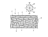
- Percentage Q 5 As shown in FIG. 3, in the cross section along the thickness direction of the fiber reinforced resin material 1, the surface direction is 0 ° and the counterclockwise direction is positive in a rectangular range (B) of 2 mm long ⁇ 125 mm wide. In this case, the fiber-reinforced resin material 1, the ratio Q 5 below is in 97% or less.
- Ratio Q 5 Ratio of the number of fiber bundles whose fiber axis direction is ⁇ 10 ° or more and 10 ° or less with respect to the total number of fiber bundles in the range (B).
- the ratio of the fiber bundle f existing in a state substantially parallel to the surface direction is ⁇ 97 ° or less and ⁇ 10 ° or less and 10 ° or less as described above. That is, the fiber bundle f having a ratio of 3% or more in the range (B) exists with an inclination exceeding 10 ° in absolute value with respect to the plane direction. Thereby, the tensile strength of the fiber reinforced resin material molded object obtained by shape
- Fiber bundle fraction Q 5 is intended a tensile strength since there is a tendency that a higher fiber-reinforced resin material molded product is obtained, the fiber axis direction is -5 ° with respect to the total number of fiber bundles in the range (B) A fiber bundle of 5 ° or less is preferable.
- the above-mentioned dispersion state in the fiber bundle constituting the fiber reinforced resin material of the present invention can be confirmed by, for example, analyzing an X-ray CT three-dimensional image of the material.
- the reinforcing fiber forming the fiber bundle is not particularly limited.
- inorganic fibers organic fibers, metal fibers, or reinforcing fibers having a hybrid configuration in combination of these can be used.
- the inorganic fibers carbon fibers, graphite fibers, Examples thereof include silicon carbide fiber, alumina fiber, tungsten carbide fiber, boron fiber, and glass fiber.
- the organic fibers include aramid fibers, high density polyethylene fibers, other general nylon fibers, and polyester fibers.
- metal fibers include fibers such as stainless steel and iron, and carbon fibers coated with metal may be used.
- carbon fibers are preferable in view of mechanical properties such as strength of the fiber-reinforced resin material molded body.
- One type of reinforcing fiber may be used alone, or two or more types may be used in combination.
- the average width L1 (FIG. 4) of the fiber bundle is preferably 2 to 12 mm, more preferably 2 to 10 mm, further preferably 3 to 8 mm, and particularly preferably 3 to 6 mm. If the average width L1 of the fiber bundle is equal to or greater than the lower limit value, the fiber reinforced resin material is more likely to flow at the time of molding, and thus molding is facilitated. If the average width L1 of the fiber bundle is equal to or less than the upper limit value, it is easy to obtain a fiber-reinforced resin material molded body having excellent physical properties such as tensile strength and tensile elastic modulus. The average width L1 of the fiber bundle is measured by the following method.
- the fiber reinforced resin material is heated in an electric furnace or the like to decompose the matrix resin composition, and 10 fiber bundles are randomly selected from the remaining fiber bundles.
- the width is measured with a vernier caliper at three positions of the both ends and the center in the fiber axis direction, and all of the measured values are averaged to obtain an average width.
- the average fiber length L2 (FIG. 4) of the fiber bundle is preferably 20 to 100 mm, more preferably 25 to 80 mm, and even more preferably 25 to 55 mm. If the fiber length L2 of the fiber bundle is equal to or greater than the lower limit, it is easy to obtain a fiber reinforced resin material molded body having excellent physical properties such as tensile strength and tensile elastic modulus. If the fiber length L2 of the fiber bundle is equal to or less than the upper limit value, the fiber reinforced resin material is more likely to flow at the time of molding, and thus molding becomes easy.
- the average fiber length L2 of the fiber bundle is measured by the following method. For each of the ten fiber bundles obtained in the same manner as the measurement of the average width, the maximum fiber length is measured with a caliper, and all of the measured values are averaged to obtain the average fiber length.
- the ratio L2 / L1 of the average fiber length L2 to the average width L1 in the fiber bundle is preferably 5 to 20, more preferably 5 to 10, and further preferably 7 to 9.
- a fiber-reinforced resin material molded body having excellent mechanical properties such as tensile strength and tensile elastic modulus can be easily obtained.
- the average thickness L3 (FIG. 4) of the fiber bundle is preferably 0.01 to 0.1 mm, more preferably 0.02 to 0.1 mm, still more preferably 0.02 to 0.08 mm, and 0.04 to 0.00 mm. Particularly preferred is 06 mm. If the average thickness L3 of the fiber bundle is equal to or greater than the lower limit, the fiber bundle can be easily handled, and further, the fiber bundle group can be easily impregnated with the matrix resin composition. If the average thickness L3 of the fiber bundle is equal to or lower than the upper limit value, a fiber-reinforced resin material molded body having excellent physical properties such as tensile strength and tensile elastic modulus can be easily obtained.
- the average thickness of the fiber bundle is measured by the following method. For each of the 10 fiber bundles obtained in the same manner as the average width measurement, the thickness was measured with three calipers at both ends and the center in the fiber axis direction, and all the measured values were averaged and averaged. Thickness.
- the ratio L1 / L3 of the average width L1 to the average thickness L3 in the fiber bundle is preferably 10 to 500, more preferably 50 to 400, and even more preferably 100 to 300. If ratio L1 / L3 is in the said range, it will become easy to obtain the fiber reinforced resin material molded object excellent in mechanical properties, such as tensile strength and a tensile elasticity modulus.
- the number of laminated fiber bundles per unit thickness (per 1 mm thickness) in the fiber reinforced resin material is preferably 8 or more, more preferably 8 to 16, and still more preferably 8 to 12. If the number of laminated fiber bundles is equal to or greater than the lower limit value, a fiber-reinforced resin material molded body having excellent mechanical properties such as tensile strength and tensile elastic modulus can be easily obtained. If the number of laminated fiber bundles is equal to or less than the upper limit value, the fiber reinforced resin material becomes easier to flow at the time of molding, and thus molding becomes easy.
- laminate means that when a fiber reinforced resin material is projected in the thickness direction, at least a part of an arbitrary fiber bundle constituting the fiber reinforced resin material (1% or more of the projected area of the fiber bundle). It means that it is in a state where it overlaps with other fiber bundles regardless of the presence or absence of contact.
- the number of laminated fiber bundles can be counted from, for example, an X-ray CT image of a fiber reinforced resin material.
- the resin component of the fiber reinforced resin material is thermally decomposed in a nitrogen atmosphere, or this resin component is dissolved and removed. Can be counted.
- the fiber mass content of the fiber reinforced resin material of the present invention is preferably 60% by mass or more, more preferably 60 to 80% by mass, and further preferably 60 to 70% by mass with respect to the total mass of the fiber reinforced resin material. If the fiber mass content is equal to or higher than the lower limit, a fiber-reinforced resin material molded article having excellent physical properties such as tensile strength and tensile elastic modulus can be easily obtained. If the fiber mass content is less than or equal to the upper limit value, the fiber-reinforced resin material is more likely to flow at the time of molding, which facilitates molding.
- thermosetting resin composition As a matrix resin composition, the composition containing a thermosetting resin is preferable.
- the thermosetting resin is not particularly limited, and examples thereof include an epoxy resin, a phenol resin, an unsaturated polyester resin, a urethane resin, a urea resin, a melamine resin, and an imide resin.
- a thermosetting resin may be used individually by 1 type, and may use 2 or more types together.
- additives such as a curing agent, an internal mold release agent, a thickener, and a stabilizer may be blended as necessary.
- the ratios Q 1 to Q 4 are all controlled to be 15% or more and the ratio Q 5 is controlled to 97% or less.
- the fiber bundle is dispersed so that the fiber axis direction is closer to random in the cross section along the surface direction, while the surface is cross section along the thickness direction. Control is performed so that the number of fiber bundles having a large inclination in the fiber axis direction with respect to the direction increases.
- the fiber reinforced resin material of the present invention is not limited to the fiber reinforced resin material 1 described above.
- the fiber reinforced resin material of the present invention may not be long.
- the manufacturing method of the fiber reinforced resin material of this invention is a method of manufacturing the fiber reinforced resin material mentioned above.
- the orientation in the surface direction and the thickness direction of the fiber bundle in the fiber reinforced resin material can be controlled by adjusting the fiber length, width, and thickness of the fiber bundle.
- the average width L′ 1 is 2 to 12 mm
- the average fiber length L′ 2 is 20 to 100 mm
- the average thickness L′ 3 is 0.
- a fiber bundle having a ratio L′ 2 / L′ 1 of 5 to 20 and a diameter of 0.01 to 0.1 mm is used.
- Impregnation step a group of sheet-like fiber bundles formed by a plurality of fiber bundles is sandwiched between a pair of resin sheets made of a matrix resin composition, and they are pressed from both sides to form the matrix resin composition into the sheet-like fiber bundle. A step of impregnating the group to obtain a fiber reinforced resin material.
- the manufacturing apparatus 100 includes a fiber bundle supply unit 10, a first carrier sheet supply unit 11, a first transport unit 20, a first coating unit 12, a cutting machine 13, and a second carrier sheet supply.
- the first carrier sheet supply unit 11 supplies the long first carrier sheet 3 drawn from the first raw fabric roll R1 to the first transport unit 20.
- the 1st conveyance part 20 is provided with the conveyor 23 which multiplied the endless belt 22 between a pair of pulleys 21a and 21b.
- the endless belt 22 is circulated by rotating the pair of pulleys 21a and 21b in the same direction, and the first carrier sheet 3 is conveyed toward the right side in the X-axis direction on the surface of the endless belt 22.
- the first coating unit 12 is located immediately above the pulley 21a side in the first transport unit 20, and includes a coater 24 that supplies a paste P made of a matrix resin composition. As the first carrier sheet 3 passes through the coater 24, the paste P is applied with a predetermined thickness on the surface of the first carrier sheet 3, and the first resin sheet S1 is formed. The first resin sheet S1 travels as the first carrier sheet 3 is conveyed.
- the fiber bundle supply unit 10 supplies the long fiber bundle f ′ toward the cutting machine 13 through the plurality of guide rolls 18 while pulling out the long fiber bundle f ′ from the plurality of bobbins 17.
- the cutting machine 13 is located above the first carrier sheet 3 at a later stage in the transport direction than the first coating unit 12.
- the cutting machine 13 continuously cuts the fiber bundle f ′ supplied from the fiber bundle supply unit 10 into a predetermined length, and includes a guide roll 25, a pinch roll 26, and a cutter roll 27. Yes.
- the guide roll 25 guides the supplied fiber bundle f 'downward while rotating.
- the pinch roll 26 rotates in the opposite direction to the guide roll 25 while sandwiching the fiber bundle f ′ with the guide roll 25.
- the cutter roll 27 cuts the fiber bundle f ′ so as to have a predetermined length while rotating.
- the fiber bundle f cut to a predetermined length by the cutter 13 is dropped and dispersed on the first resin sheet S1, and the sheet-like fiber bundle group F is formed.
- the second carrier sheet supply unit 14 supplies the long second carrier sheet 4 drawn out from the second original roll R2 to the second transport unit 28.
- the second transport unit 28 is positioned above the first carrier sheet 3 transported by the conveyor 23 and includes a plurality of guide rolls 29.
- the second transport unit 28 transports the second carrier sheet 4 supplied from the second carrier sheet supply unit 14 in the direction opposite to the first carrier sheet 3 (left side in the X-axis direction), and then the transport direction. Is reversed in the same direction as the first carrier sheet 3 by a plurality of guide rolls 29.
- the second coating unit 15 includes a coater 30 that is located immediately above the second carrier sheet 4 being conveyed in the direction opposite to the first carrier sheet 3 and that supplies a paste P made of a matrix resin composition. Yes. By passing the second carrier sheet 4 through the coater 30, the paste P is applied on the surface of the second carrier sheet 4 with a predetermined thickness, and the second resin sheet S2 is formed. The second resin sheet S2 travels as the second carrier sheet 4 is conveyed.
- the impregnation part 16 is located in the back
- the bonding mechanism 31 is located above the pulley 21 b of the conveyor 23 and includes a plurality of bonding rolls 33.
- the some bonding roll 33 is arrange
- the plurality of bonding rolls 33 are arranged so that the second carrier sheet 4 gradually approaches the first carrier sheet 3.
- the first carrier sheet 3 and the second carrier sheet 4 are conveyed while being superimposed with the first resin sheet S1, the sheet-like fiber bundle group F, and the second resin sheet S2 sandwiched therebetween.
- stacking precursor S3 what laminated
- the pressurizing mechanism 32 is located at the subsequent stage of the bonding mechanism 31 and has an endless belt 35b between a pair of pulleys 34c and 34d and a lower conveyor 36A in which an endless belt 35a is hung between the pair of pulleys 34a and 34b. And an upper conveyor 36B.
- the lower conveyor 36A and the upper conveyor 36B are arranged to face each other in a state where the endless belts 35a and 35b are abutted with each other.
- the pair of pulleys 34a and 34b of the lower conveyor 36A are rotated in the same direction, whereby the endless belt 35a is circulated. Further, in the pressurizing mechanism 32, the pair of pulleys 34c and 34d of the upper conveyor 36B are rotated in the same direction, whereby the endless belt 35b is rotated in the reverse direction at the same speed as the endless belt 35a. Thereby, the lamination
- the pressurizing mechanism 32 is further provided with a plurality of lower rolls 37a and a plurality of upper rolls 37b.
- the plurality of lower rolls 37a are arranged side by side in the transport direction in contact with the back surface of the butted portion of the endless belt 35a.
- the plurality of upper rolls 37b are arranged side by side in the transport direction in contact with the back surface of the butted portion of the endless belt 35b.
- the some lower side roll 37a and the some upper side roll 37b are arrange
- the lamination precursor S3 is pressurized by the plurality of lower rolls 37a and the plurality of upper rolls 37b while the bonding sheet S3 passes between the endless belts 35a and 35b.
- the fiber reinforced resin in a state where the matrix resin composition of the first resin sheet S1 and the second resin sheet S2 is impregnated into the sheet-like fiber bundle group F and is sandwiched between the first carrier sheet 3 and the second carrier sheet 4.
- Material 1 (SMC) is formed.
- the storage container 40 is a container for storing the raw fabric R in which the fiber reinforced resin material 1 is sandwiched between the first carrier sheet 3 and the second carrier sheet 4.
- the following spraying step and impregnation step are sequentially performed.
- Spreading step a step of continuously cutting the long fiber bundle f ′ and spraying the plurality of cut fiber bundles f on the first resin sheet S1 to form a sheet-like fiber bundle group F.
- Impregnation step the second resin sheet S2 is laminated on the sheet-like fiber bundle group F to form a precursor laminate S3, the precursor laminate S3 is pressed from both sides, and the matrix resin composition is applied to the sheet-like fiber bundle group F.
- the first carrier sheet supply unit 11 pulls out the long first carrier sheet 3 from the first raw fabric roll R1 and supplies it to the first transport unit 20, and the first coating unit 12 pastes the paste P. Is applied at a predetermined thickness to form the first resin sheet S1. By transporting the first carrier sheet 3 by the first transport unit 20, the first resin sheet S1 on the first carrier sheet 3 is caused to travel.
- the fiber bundle f ′ supplied from the fiber bundle supply unit 10 is continuously cut by the cutting machine 13 so as to have a predetermined length, and the cut fiber bundle f is dropped onto the first resin sheet S1 and dispersed. .
- distributed by the random fiber orientation is continuously formed on 1st resin sheet S1 to drive
- a long fiber bundle f ′ having a width of 2 to 10 mm and a thickness of 0.02 to 0.11 mm is supplied to the cutting machine 13. Then, the fiber is cut so that the average fiber length L2 is 20 to 100 mm.
- the cut fiber bundle f (chopped fiber bundle) has an average width L′ 1 of 2 to 10 mm, an average fiber length L′ 2 of 20 to 100 mm, and an average thickness L′ 3 of 0.02 to 0.1 mm.
- a fiber bundle having a ratio L′ 2 / L′ 1 of 5 to 20 is obtained.
- distribution process will not be limited to the said method, if each dimension of the fiber bundle after cutting is adjusted in the said range. For example, when performing fiber opening to widen the fiber bundle in the width direction before cutting, fiber splitting to divide the fiber bundle in the width direction, or the like, even a method using a fiber bundle having a size different from the above method Good.
- the average width L′ 1 of the fiber bundles forming the sheet-like fiber bundle group is preferably 2 to 12 mm, more preferably 2 to 10 mm from the viewpoint that the ratios Q 1 to Q 5 can be easily controlled within the above-described range. It is more preferably ⁇ 8 mm, particularly preferably 3 to 6 mm.
- the average fiber length L′ 2 of the fiber bundles forming the sheet-like fiber bundle group is preferably 20 to 100 mm, more preferably 25 to 80 mm, and further preferably 25 to 55 mm.
- the average thickness L′ 3 of the fiber bundles forming the sheet-like fiber bundle group is preferably 0.01 to 0.1 mm, more preferably 0.02 to 0.1 mm, and 0.02 to 0.08 mm.
- the ratio L′ 2 / L′ 1 is preferably 5 to 20, more preferably 5 to 10, and even more preferably 7 to 9 for the same reason.
- the ratio L′ 1 / L′ 3 is preferably 10 to 500, more preferably 50 to 400, still more preferably 100 to 300, and particularly preferably 100 to 200 for the same reason.
- the second carrier sheet supply unit 14 pulls out the long second carrier sheet 4 from the second raw fabric roll R ⁇ b> 2 and supplies it to the second transport unit 28.
- the second coating unit 15 applies the paste P with a predetermined thickness on the surface of the second carrier sheet 4 to form the second resin sheet S2.
- 2nd resin sheet S2 is made to travel by conveying the 2nd carrier sheet 4, and the 2nd resin sheet S2 is bonded together on the sheet-like fiber bundle group F with the bonding mechanism 31, and is laminated.
- the precursor precursor S3 in which the material precursor in which the sheet-like fiber bundle group F is sandwiched between the first resin sheet S1 and the second resin sheet S2 is sandwiched between the first carrier sheet 3 and the second carrier sheet 4 is obtained. It is formed continuously.
- the pressurization mechanism 32 pressurizes the precursor laminate S3 from both sides, impregnates the sheet-like fiber bundle group F with the matrix resin composition of the first resin sheet S1 and the second resin sheet S2, and the first carrier sheet 3 and the first carrier sheet 3
- the fiber reinforced resin material 1 is formed between the two carrier sheets 4.
- a sheet-like fiber bundle group is formed with fiber bundles in which the average width L′ 1, the average fiber length L′ 2, the average thickness L′ 3, and the ratio L′ 2 / L′ 1 are controlled, and pressed from both sides.
- a fiber reinforced resin material is formed in which the orientation state of the fiber bundle satisfies each of the ratios Q 1 to Q 5 .
- the raw fabric R in a state where the fiber reinforced resin material 1 is sandwiched between the first carrier sheet 3 and the second carrier sheet 4 is transferred to the storage container 40 and stored.
- the fiber reinforced resin material molded body obtained by molding the fiber reinforced resin material has excellent mechanical properties such as tensile strength and tensile elastic modulus.
- the manufacturing method of the fiber reinforced resin material of the present invention is not limited to the method of continuously manufacturing the long fiber reinforced resin material as described above. There may be.
- Example 1 The simulation was performed using LS-DYNA (manufactured by LSTC) as simulation software. In the simulation, a fiber bundle composed of 15,000 carbon fibers having a width of 6 mm, a fiber length of 50.8 mm, and a thickness of 0.055 mm was set. Next, the fiber bundle having a fiber weight content of 66% is dropped from a height of 0.5 m to form a sheet-like fiber bundle group having a thickness of 2.5 mm, and the sheet-like fiber is made of a resin sheet made of vinyl ester.
- LS-DYNA manufactured by LSTC
- the resin is impregnated by applying pressure until the thickness becomes 2 mm to obtain a fiber reinforced resin material having a length of 25.4 mm, a width of 150 mm, and a thickness of 2 mm.
- the ratios Q 1 to Q 5 were calculated for the fiber reinforced resin material in this simulation.
- the range (A) for calculating the ratios Q 1 to Q 4 is set so as to exclude the 10 mm portion from the edges on both sides in the lateral direction, and the fiber bundle targeted by the ratio Q 5 is the range ( B) A fiber bundle having a fiber axis direction with respect to the total number of fiber bundles in the range of ⁇ 10 ° to 10 °.
- Table 1 shows the simulation results of a cured product obtained by curing the matrix resin in the fiber reinforced resin material.
- the tensile strength was 307 MPa and the tensile modulus was 47.1 GPa.
- the ratio Q 5 when the target fiber bundle was a fiber bundle having a fiber axis direction of ⁇ 5 ° or more and 5 ° or less with respect to the total number of fiber bundles within the range (B) was 92.4%.
- the tensile strength was 342 MPa and the tensile modulus was 42.4 GPa.
- Example 1 A simulation was performed in the same manner as in Example 1 except that the thickness of the fiber bundle was changed to 0.11 mm. The results are shown in Table 1. The tensile strength was 232 MPa and the tensile elastic modulus was 41.7 GPa. Further, the ratio Q 5 when the target fiber bundle was a fiber bundle having a fiber axis direction of ⁇ 5 ° or more and 5 ° or less with respect to the total number of fiber bundles within the range (B) was 97.7%. . Furthermore, as a result of actually measuring the physical property values of the cured product of the fiber reinforced resin material obtained under the same conditions as described above, the tensile strength was 239 MPa and the tensile elastic modulus was 44.0 GPa.
- Example 2 A simulation was performed in the same manner as in Example 1 except that the thickness of the fiber bundle was changed to 0.15 mm, the width of the fiber bundle was changed to 14 mm, and the fiber length was changed to 25.4 mm. The results are shown in Table 1. The tensile strength was 146 MPa and the tensile modulus was 30.6 GPa. Further, the ratio Q 5 when the target fiber bundle was a fiber bundle having a fiber axis direction of ⁇ 5 ° or more and 5 ° or less with respect to the total number of fiber bundles within the range (B) was 99.8%. .
- the ratio Q 5 is more than 97%.
- the obtained fiber reinforced resin material molded body (cured product) had a higher tensile strength.
- the ratios Q 1 to Q 4 were less than 15%, and the tensile strength and tensile modulus were higher than those of Comparative Example 2 in which the ratio Q 5 was more than 97%.
- the fiber reinforced resin material of the present invention By using the fiber reinforced resin material of the present invention, a fiber reinforced resin material molded body having high mechanical properties such as tensile strength and tensile elastic modulus can be obtained. If it is the manufacturing method of the fiber reinforced resin material of this invention, the fiber reinforced resin material from which the fiber reinforced resin material molded object with high mechanical properties, such as tensile strength and a tensile elasticity modulus, is obtained can be manufactured.
Landscapes
- Engineering & Computer Science (AREA)
- Mechanical Engineering (AREA)
- Chemical & Material Sciences (AREA)
- Composite Materials (AREA)
- Textile Engineering (AREA)
- Reinforced Plastic Materials (AREA)
Priority Applications (4)
| Application Number | Priority Date | Filing Date | Title |
|---|---|---|---|
| CN201780018597.4A CN108883548A (zh) | 2016-03-24 | 2017-03-21 | 纤维增强树脂材料及其制造方法 |
| EP17770199.2A EP3434435A4 (en) | 2016-03-24 | 2017-03-21 | FIBER REINFORCED RESIN MATERIAL AND MANUFACTURING METHOD THEREFOR |
| JP2017517142A JP6409964B2 (ja) | 2016-03-24 | 2017-03-21 | 繊維強化樹脂材料の製造方法 |
| US16/135,021 US20190016088A1 (en) | 2016-03-24 | 2018-09-19 | Fiber-reinforced resin material and manufacturing method therefor |
Applications Claiming Priority (2)
| Application Number | Priority Date | Filing Date | Title |
|---|---|---|---|
| JP2016-059810 | 2016-03-24 | ||
| JP2016059810 | 2016-03-24 |
Related Child Applications (1)
| Application Number | Title | Priority Date | Filing Date |
|---|---|---|---|
| US16/135,021 Continuation US20190016088A1 (en) | 2016-03-24 | 2018-09-19 | Fiber-reinforced resin material and manufacturing method therefor |
Publications (1)
| Publication Number | Publication Date |
|---|---|
| WO2017164157A1 true WO2017164157A1 (ja) | 2017-09-28 |
Family
ID=59899434
Family Applications (1)
| Application Number | Title | Priority Date | Filing Date |
|---|---|---|---|
| PCT/JP2017/011165 WO2017164157A1 (ja) | 2016-03-24 | 2017-03-21 | 繊維強化樹脂材料及びその製造方法 |
Country Status (5)
| Country | Link |
|---|---|
| US (1) | US20190016088A1 (zh) |
| EP (1) | EP3434435A4 (zh) |
| JP (1) | JP6409964B2 (zh) |
| CN (1) | CN108883548A (zh) |
| WO (1) | WO2017164157A1 (zh) |
Cited By (1)
| Publication number | Priority date | Publication date | Assignee | Title |
|---|---|---|---|---|
| WO2020090877A1 (ja) | 2018-10-31 | 2020-05-07 | 東レ株式会社 | 繊維強化樹脂成形材料およびその成形品 |
Families Citing this family (4)
| Publication number | Priority date | Publication date | Assignee | Title |
|---|---|---|---|---|
| DE102019100297A1 (de) * | 2019-01-08 | 2020-07-09 | Gühring KG | Verfahren zur Herstellung einer Faser-Kunststoff-Verbund Werkzeugkomponente und Faser-Kunststoff-Verbund Werkzeugkomponente |
| EP3950283A4 (en) * | 2019-03-27 | 2022-12-21 | Toray Industries, Inc. | FIBER REINFORCED RESIN MOLDING MATERIAL MOLDING PRODUCT AND METHOD OF MANUFACTURE THEREOF |
| US11926073B2 (en) | 2019-11-25 | 2024-03-12 | Dic Corporation | Methods for producing sheet molding compound and for producing molded product |
| KR102390556B1 (ko) * | 2021-11-19 | 2022-04-27 | (주)테라엔지니어링 | 프리프레그의 배열방향과 smc 시트의 유동방향을 고려한 smc 시트와 프리프레그의 일체 성형 방법 |
Citations (4)
| Publication number | Priority date | Publication date | Assignee | Title |
|---|---|---|---|---|
| JP2009114612A (ja) * | 2007-10-16 | 2009-05-28 | Toray Ind Inc | チョップド繊維束および成形材料の製造方法、成形材料、繊維強化プラスチック |
| WO2013115337A1 (ja) * | 2012-01-31 | 2013-08-08 | 帝人株式会社 | ランダムマットおよび繊維強化複合材料 |
| JP2013202890A (ja) * | 2012-03-28 | 2013-10-07 | Mitsubishi Rayon Co Ltd | 成形材料とその製造方法 |
| WO2017069153A1 (ja) * | 2015-10-21 | 2017-04-27 | 三菱レイヨン株式会社 | チョップド繊維束の製造装置および製造方法、繊維強化樹脂成形材料の製造装置および製造方法、炭素繊維束用切断刃、ならびに炭素繊維束用ロータリーカッタ |
Family Cites Families (5)
| Publication number | Priority date | Publication date | Assignee | Title |
|---|---|---|---|---|
| US5164255A (en) * | 1989-08-31 | 1992-11-17 | E. I. Du Pont De Nemours And Company | Nonwoven preform sheets of fiber reinforced resin chips |
| JPH09109310A (ja) * | 1995-10-20 | 1997-04-28 | Ykk Corp | 成形シート材料の製造方法、その方法によって製造される繊維強化成形シート材料およびそれを用いた安全靴の先芯 |
| FR2806425B1 (fr) * | 2000-03-16 | 2002-07-12 | Hexcel Composites | Produit intermediaire composite, procede de production d'un tel produit et utilisation a titre de materiau de moulage |
| JP2008254191A (ja) * | 2007-03-30 | 2008-10-23 | Honda Motor Co Ltd | 炭素繊維複合材料製造装置、これを用いた炭素繊維複合材料製造方法および炭素繊維複合材料 |
| ES2367211T3 (es) * | 2008-07-24 | 2011-10-31 | Alenia Aeronautica S.P.A. | Un método para reciclar desperdicios de materiales preimpregnados. |
-
2017
- 2017-03-21 JP JP2017517142A patent/JP6409964B2/ja active Active
- 2017-03-21 EP EP17770199.2A patent/EP3434435A4/en not_active Withdrawn
- 2017-03-21 WO PCT/JP2017/011165 patent/WO2017164157A1/ja active Application Filing
- 2017-03-21 CN CN201780018597.4A patent/CN108883548A/zh active Pending
-
2018
- 2018-09-19 US US16/135,021 patent/US20190016088A1/en not_active Abandoned
Patent Citations (4)
| Publication number | Priority date | Publication date | Assignee | Title |
|---|---|---|---|---|
| JP2009114612A (ja) * | 2007-10-16 | 2009-05-28 | Toray Ind Inc | チョップド繊維束および成形材料の製造方法、成形材料、繊維強化プラスチック |
| WO2013115337A1 (ja) * | 2012-01-31 | 2013-08-08 | 帝人株式会社 | ランダムマットおよび繊維強化複合材料 |
| JP2013202890A (ja) * | 2012-03-28 | 2013-10-07 | Mitsubishi Rayon Co Ltd | 成形材料とその製造方法 |
| WO2017069153A1 (ja) * | 2015-10-21 | 2017-04-27 | 三菱レイヨン株式会社 | チョップド繊維束の製造装置および製造方法、繊維強化樹脂成形材料の製造装置および製造方法、炭素繊維束用切断刃、ならびに炭素繊維束用ロータリーカッタ |
Non-Patent Citations (1)
| Title |
|---|
| See also references of EP3434435A4 * |
Cited By (2)
| Publication number | Priority date | Publication date | Assignee | Title |
|---|---|---|---|---|
| WO2020090877A1 (ja) | 2018-10-31 | 2020-05-07 | 東レ株式会社 | 繊維強化樹脂成形材料およびその成形品 |
| US12030218B2 (en) | 2018-10-31 | 2024-07-09 | Toray Industries, Inc. | Fiber-reinforced resin molding material and molded article thereof |
Also Published As
| Publication number | Publication date |
|---|---|
| JPWO2017164157A1 (ja) | 2018-03-29 |
| US20190016088A1 (en) | 2019-01-17 |
| EP3434435A1 (en) | 2019-01-30 |
| CN108883548A (zh) | 2018-11-23 |
| JP6409964B2 (ja) | 2018-10-24 |
| EP3434435A4 (en) | 2019-03-27 |
Similar Documents
| Publication | Publication Date | Title |
|---|---|---|
| JP6409964B2 (ja) | 繊維強化樹脂材料の製造方法 | |
| JP6521026B2 (ja) | チョップド繊維束の製造装置および製造方法、繊維強化樹脂成形材料の製造装置、炭素繊維束用切断刃、ならびに炭素繊維束用ロータリーカッタ | |
| JP6943199B2 (ja) | Smcの製造方法及びsmc | |
| CN107614579B (zh) | 带状预浸料及纤维强化成形体 | |
| WO2020071466A1 (ja) | 薄層テープの自動積層方法及び装置 | |
| EP3587090A1 (en) | Method and apparatus for manufacturing a sheet moulding compound (smc) | |
| JP2020059145A (ja) | プリプレグテープの積層装置及び積層方法 | |
| CN112739752A (zh) | 纤维增强树脂成型材料及成型品 | |
| JP6593557B2 (ja) | 繊維強化樹脂成形材料の製造方法及び繊維強化樹脂成形材料製造装置 | |
| JP7259229B2 (ja) | チョップド繊維束マット | |
| JP2018126975A (ja) | シートモールディングコンパウンドの製造方法及びシートモールディングコンパウンドの製造装置 | |
| WO2020195756A1 (ja) | 繊維強化樹脂成形材料成形品およびその製造方法 | |
| WO2018147331A1 (ja) | 繊維強化樹脂シート | |
| EP3616870A1 (en) | Fiber-reinforced resin molding material and method for manufacturing same, and fiber-reinforced resin molded article | |
| WO2023100702A1 (ja) | シートプリプレグの製造方法 | |
| JP2021028178A (ja) | 複合材料成形品及びその製造方法 | |
| WO2022131166A1 (ja) | 接続部、シートモールディングコンパウンドの製造方法、および方法 | |
| CN112955294B (zh) | 纤维增强树脂成型材料及其成型品 | |
| JP6468351B2 (ja) | 繊維強化樹脂材料積層体及びその製造方法 | |
| JP2020023069A (ja) | 造形装置 | |
| JP6876267B2 (ja) | 繊維束の分割方法、長尺の繊維束、及び繊維強化樹脂材料の製造方法 | |
| JP2016190355A (ja) | 積層基材 | |
| CN108858882B (zh) | 制造纤维增强树脂材料的装置 | |
| JP2020059144A (ja) | 薄層プリプレグテープの自動積層方法及び装置 |
Legal Events
| Date | Code | Title | Description |
|---|---|---|---|
| ENP | Entry into the national phase |
Ref document number: 2017517142 Country of ref document: JP Kind code of ref document: A |
|
| NENP | Non-entry into the national phase |
Ref country code: DE |
|
| WWE | Wipo information: entry into national phase |
Ref document number: 2017770199 Country of ref document: EP |
|
| ENP | Entry into the national phase |
Ref document number: 2017770199 Country of ref document: EP Effective date: 20181024 |
|
| 121 | Ep: the epo has been informed by wipo that ep was designated in this application |
Ref document number: 17770199 Country of ref document: EP Kind code of ref document: A1 |