WO2017164152A1 - 空調運転制御装置、空調システム、空調運転制御方法及びプログラム - Google Patents
空調運転制御装置、空調システム、空調運転制御方法及びプログラム Download PDFInfo
- Publication number
- WO2017164152A1 WO2017164152A1 PCT/JP2017/011138 JP2017011138W WO2017164152A1 WO 2017164152 A1 WO2017164152 A1 WO 2017164152A1 JP 2017011138 W JP2017011138 W JP 2017011138W WO 2017164152 A1 WO2017164152 A1 WO 2017164152A1
- Authority
- WO
- WIPO (PCT)
- Prior art keywords
- expansion valve
- air conditioning
- unit
- refrigerant
- conditioning system
- Prior art date
Links
Images

Classifications
-
- F—MECHANICAL ENGINEERING; LIGHTING; HEATING; WEAPONS; BLASTING
- F25—REFRIGERATION OR COOLING; COMBINED HEATING AND REFRIGERATION SYSTEMS; HEAT PUMP SYSTEMS; MANUFACTURE OR STORAGE OF ICE; LIQUEFACTION SOLIDIFICATION OF GASES
- F25B—REFRIGERATION MACHINES, PLANTS OR SYSTEMS; COMBINED HEATING AND REFRIGERATION SYSTEMS; HEAT PUMP SYSTEMS
- F25B49/00—Arrangement or mounting of control or safety devices
- F25B49/02—Arrangement or mounting of control or safety devices for compression type machines, plants or systems
-
- F—MECHANICAL ENGINEERING; LIGHTING; HEATING; WEAPONS; BLASTING
- F24—HEATING; RANGES; VENTILATING
- F24F—AIR-CONDITIONING; AIR-HUMIDIFICATION; VENTILATION; USE OF AIR CURRENTS FOR SCREENING
- F24F11/00—Control or safety arrangements
- F24F11/89—Arrangement or mounting of control or safety devices
-
- F—MECHANICAL ENGINEERING; LIGHTING; HEATING; WEAPONS; BLASTING
- F25—REFRIGERATION OR COOLING; COMBINED HEATING AND REFRIGERATION SYSTEMS; HEAT PUMP SYSTEMS; MANUFACTURE OR STORAGE OF ICE; LIQUEFACTION SOLIDIFICATION OF GASES
- F25B—REFRIGERATION MACHINES, PLANTS OR SYSTEMS; COMBINED HEATING AND REFRIGERATION SYSTEMS; HEAT PUMP SYSTEMS
- F25B13/00—Compression machines, plants or systems, with reversible cycle
-
- F—MECHANICAL ENGINEERING; LIGHTING; HEATING; WEAPONS; BLASTING
- F25—REFRIGERATION OR COOLING; COMBINED HEATING AND REFRIGERATION SYSTEMS; HEAT PUMP SYSTEMS; MANUFACTURE OR STORAGE OF ICE; LIQUEFACTION SOLIDIFICATION OF GASES
- F25B—REFRIGERATION MACHINES, PLANTS OR SYSTEMS; COMBINED HEATING AND REFRIGERATION SYSTEMS; HEAT PUMP SYSTEMS
- F25B2313/00—Compression machines, plants or systems with reversible cycle not otherwise provided for
- F25B2313/023—Compression machines, plants or systems with reversible cycle not otherwise provided for using multiple indoor units
- F25B2313/0233—Compression machines, plants or systems with reversible cycle not otherwise provided for using multiple indoor units in parallel arrangements
-
- F—MECHANICAL ENGINEERING; LIGHTING; HEATING; WEAPONS; BLASTING
- F25—REFRIGERATION OR COOLING; COMBINED HEATING AND REFRIGERATION SYSTEMS; HEAT PUMP SYSTEMS; MANUFACTURE OR STORAGE OF ICE; LIQUEFACTION SOLIDIFICATION OF GASES
- F25B—REFRIGERATION MACHINES, PLANTS OR SYSTEMS; COMBINED HEATING AND REFRIGERATION SYSTEMS; HEAT PUMP SYSTEMS
- F25B2313/00—Compression machines, plants or systems with reversible cycle not otherwise provided for
- F25B2313/031—Sensor arrangements
- F25B2313/0314—Temperature sensors near the indoor heat exchanger
-
- F—MECHANICAL ENGINEERING; LIGHTING; HEATING; WEAPONS; BLASTING
- F25—REFRIGERATION OR COOLING; COMBINED HEATING AND REFRIGERATION SYSTEMS; HEAT PUMP SYSTEMS; MANUFACTURE OR STORAGE OF ICE; LIQUEFACTION SOLIDIFICATION OF GASES
- F25B—REFRIGERATION MACHINES, PLANTS OR SYSTEMS; COMBINED HEATING AND REFRIGERATION SYSTEMS; HEAT PUMP SYSTEMS
- F25B2313/00—Compression machines, plants or systems with reversible cycle not otherwise provided for
- F25B2313/031—Sensor arrangements
- F25B2313/0315—Temperature sensors near the outdoor heat exchanger
-
- F—MECHANICAL ENGINEERING; LIGHTING; HEATING; WEAPONS; BLASTING
- F25—REFRIGERATION OR COOLING; COMBINED HEATING AND REFRIGERATION SYSTEMS; HEAT PUMP SYSTEMS; MANUFACTURE OR STORAGE OF ICE; LIQUEFACTION SOLIDIFICATION OF GASES
- F25B—REFRIGERATION MACHINES, PLANTS OR SYSTEMS; COMBINED HEATING AND REFRIGERATION SYSTEMS; HEAT PUMP SYSTEMS
- F25B2500/00—Problems to be solved
- F25B2500/16—Lubrication
-
- F—MECHANICAL ENGINEERING; LIGHTING; HEATING; WEAPONS; BLASTING
- F25—REFRIGERATION OR COOLING; COMBINED HEATING AND REFRIGERATION SYSTEMS; HEAT PUMP SYSTEMS; MANUFACTURE OR STORAGE OF ICE; LIQUEFACTION SOLIDIFICATION OF GASES
- F25B—REFRIGERATION MACHINES, PLANTS OR SYSTEMS; COMBINED HEATING AND REFRIGERATION SYSTEMS; HEAT PUMP SYSTEMS
- F25B2500/00—Problems to be solved
- F25B2500/27—Problems to be solved characterised by the stop of the refrigeration cycle
-
- F—MECHANICAL ENGINEERING; LIGHTING; HEATING; WEAPONS; BLASTING
- F25—REFRIGERATION OR COOLING; COMBINED HEATING AND REFRIGERATION SYSTEMS; HEAT PUMP SYSTEMS; MANUFACTURE OR STORAGE OF ICE; LIQUEFACTION SOLIDIFICATION OF GASES
- F25B—REFRIGERATION MACHINES, PLANTS OR SYSTEMS; COMBINED HEATING AND REFRIGERATION SYSTEMS; HEAT PUMP SYSTEMS
- F25B2600/00—Control issues
- F25B2600/25—Control of valves
- F25B2600/2513—Expansion valves
-
- F—MECHANICAL ENGINEERING; LIGHTING; HEATING; WEAPONS; BLASTING
- F25—REFRIGERATION OR COOLING; COMBINED HEATING AND REFRIGERATION SYSTEMS; HEAT PUMP SYSTEMS; MANUFACTURE OR STORAGE OF ICE; LIQUEFACTION SOLIDIFICATION OF GASES
- F25B—REFRIGERATION MACHINES, PLANTS OR SYSTEMS; COMBINED HEATING AND REFRIGERATION SYSTEMS; HEAT PUMP SYSTEMS
- F25B2700/00—Sensing or detecting of parameters; Sensors therefor
- F25B2700/19—Pressures
- F25B2700/193—Pressures of the compressor
- F25B2700/1931—Discharge pressures
-
- F—MECHANICAL ENGINEERING; LIGHTING; HEATING; WEAPONS; BLASTING
- F25—REFRIGERATION OR COOLING; COMBINED HEATING AND REFRIGERATION SYSTEMS; HEAT PUMP SYSTEMS; MANUFACTURE OR STORAGE OF ICE; LIQUEFACTION SOLIDIFICATION OF GASES
- F25B—REFRIGERATION MACHINES, PLANTS OR SYSTEMS; COMBINED HEATING AND REFRIGERATION SYSTEMS; HEAT PUMP SYSTEMS
- F25B2700/00—Sensing or detecting of parameters; Sensors therefor
- F25B2700/21—Temperatures
- F25B2700/2115—Temperatures of a compressor or the drive means therefor
- F25B2700/21151—Temperatures of a compressor or the drive means therefor at the suction side of the compressor
-
- F—MECHANICAL ENGINEERING; LIGHTING; HEATING; WEAPONS; BLASTING
- F25—REFRIGERATION OR COOLING; COMBINED HEATING AND REFRIGERATION SYSTEMS; HEAT PUMP SYSTEMS; MANUFACTURE OR STORAGE OF ICE; LIQUEFACTION SOLIDIFICATION OF GASES
- F25B—REFRIGERATION MACHINES, PLANTS OR SYSTEMS; COMBINED HEATING AND REFRIGERATION SYSTEMS; HEAT PUMP SYSTEMS
- F25B2700/00—Sensing or detecting of parameters; Sensors therefor
- F25B2700/21—Temperatures
- F25B2700/2115—Temperatures of a compressor or the drive means therefor
- F25B2700/21152—Temperatures of a compressor or the drive means therefor at the discharge side of the compressor
Definitions
- the present invention relates to an air conditioning operation control device, an air conditioning system, an air conditioning operation control method, and a program.
- the amount of refrigerant flowing into the compressor increases when heating operation is performed with some indoor units stopped.
- the lubricating oil of the compressor may be diluted with a refrigerant. Dilution of the lubricant can affect the stability of the compressor operation.
- the multi-room air conditioner described in Patent Document 1 reduces the amount of refrigerant flowing into the compressor by allowing the refrigerant to flow into the stopped indoor unit.
- an electromagnetic valve is provided in the refrigerant piping at the entrance and exit of each of the two indoor heat exchangers.
- a throttle mechanism and a check valve are provided in parallel between the cooling-side inlet-side electromagnetic valve that serves as the inlet side to the indoor heat exchanger during cooling and the indoor heat exchanger.
- a capillary for returning the refrigerant to the compressor suction side pipe is provided between the cooling-side inlet-side electromagnetic valve, the throttle mechanism, and the check valve.
- the multi-room air conditioner described in Patent Document 1 opens a solenoid valve at both the entrance and exit of the indoor heat exchanger during operation during heating operation.
- the stopped indoor heat exchanger only the inlet side solenoid valve during cooling is opened.
- Patent Literature 1 in this state, the interior of the stopped indoor heat exchanger is pulled to the compressor low pressure side by the capillary and is at a low pressure, and a sufficient amount of surplus refrigerant can be stored. Has been.
- an electromagnetic valve is provided on the refrigerant piping on both sides of the inlet / outlet of the indoor heat exchanger, and a throttle mechanism and a reverse mechanism are provided between the inlet side electromagnetic valve during cooling and the indoor heat exchanger.
- a configuration in which a stop valve and a capillary are provided is necessary. If a simpler configuration can be achieved, the manufacturing cost of the device can be reduced.
- the present invention provides an air-conditioning operation control device, an air-conditioning system, an air-conditioning operation control method, and a program capable of making the air-conditioning system simpler and reducing the amount of refrigerant flowing into the compressor. .
- the air-conditioning operation control apparatus includes a single outdoor unit, a plurality of indoor units, and a plurality of air conditioners that are provided on the refrigerant outlet side during heating of each of the plurality of indoor units.
- the operation mode determination unit that determines whether or not the air conditioning system body including the refrigerant circuit including the expansion valve is in the heating operation, and the operation mode determination unit determines that the air conditioning system body is in the heating operation.
- the stop determination unit that determines whether there is a stopped indoor unit among the plurality of indoor units, and the stop determination unit determines that there is the stopped indoor unit, the stop determination unit determines that there is a stop.
- An expansion valve control unit that closes the expansion valve after the expansion valve connected to the indoor unit is opened.
- the expansion valve control unit opens an expansion valve connected to the stopped indoor unit to a predetermined opening degree, and after a predetermined time has elapsed since the expansion valve is opened to a predetermined opening degree.
- the expansion valve may be fully closed.
- the expansion valve control unit may control the opening degree of the expansion valve based on the temperature of the refrigerant flowing through the refrigerant circuit after closing the expansion valve connected to the stopped indoor unit. Good.
- the expansion valve control unit is based on a difference between a temperature of the refrigerant flowing into the compressor and a temperature of the refrigerant discharged from the compressor and flowed into an outdoor heat exchanger provided in the outdoor unit.
- the opening degree of the expansion valve may be controlled.
- the expansion valve control unit may control the opening degree of the expansion valve based on the temperature of the refrigerant discharged from the compressor.
- the air conditioning system includes one outdoor unit, a plurality of indoor units, and a plurality of expansions provided one by one on the refrigerant outlet side during heating of each of the plurality of indoor units.
- An air conditioning system main body including a refrigerant circuit including a valve and any one of the air conditioning operation control devices described above are provided.
- the air-conditioning operation control method includes a single outdoor unit, a plurality of indoor units, and a plurality of one provided on the refrigerant outlet side during heating of each of the plurality of indoor units.
- a step of determining whether or not an air conditioning system main body having a refrigerant circuit including an expansion valve is in a heating operation, and when determining that the air conditioning system main body is in a heating operation, among the plurality of indoor units A step of determining whether or not there is a stopped indoor unit, and when it is determined that there is a stopped indoor unit, the expansion valve connected to the stopped indoor unit is opened. And an expansion valve control unit that closes the expansion valve that has been opened.
- the fourth aspect of the present invention there are a plurality of programs provided in the computer, one outdoor unit, a plurality of indoor units, and one each on the refrigerant outlet side during heating of each of the plurality of indoor units.
- a step of determining whether or not an air conditioning system main body having a refrigerant circuit including an expansion valve is in a heating operation, and when determining that the air conditioning system main body is in a heating operation, among the plurality of indoor units A step of determining whether or not there is a stopped indoor unit, and when it is determined that there is a stopped indoor unit, the expansion valve connected to the stopped indoor unit is opened. It is a program for performing a process and a process of closing the expansion valve that has been opened.
- the air conditioning system can be configured more simply and the amount of refrigerant flowing into the compressor can be reduced.
- FIG. 1 is a schematic configuration diagram showing an apparatus configuration of an air conditioning system according to an embodiment of the present invention.
- the air conditioning system (air conditioning system) 1 includes an air conditioning operation control device 100, a first indoor unit 210a, a second indoor unit 210b, and an outdoor unit 220.
- the first indoor unit 210a includes a first indoor heat exchanger 211a and a first indoor heat exchanger temperature sensor 315a.
- the second indoor unit 210b includes a second indoor heat exchanger 211b and a second indoor heat exchanger temperature sensor 315b.
- the outdoor unit 220 includes an expansion valve side first service valve 221a, an expansion valve side second service valve 221b, a first expansion valve 222a, a second expansion valve 222b, an outdoor heat exchanger 223, and a four-way valve 224. , Accumulator 225, compressor 226, four-way valve side first service valve 227a, four-way valve side second service valve 227b, compressor suction side temperature sensor 311, outdoor heat exchanger temperature sensor 312, compressor An outlet temperature sensor 313 and a compressor outlet pressure sensor 314 are provided.
- the first indoor unit 210a and the second indoor unit 210b are collectively referred to as the indoor unit 210.
- the first indoor heat exchanger 211a and the second indoor heat exchanger 211b are collectively referred to as an indoor heat exchanger 211.
- the first indoor heat exchanger temperature sensor 315a and the second indoor heat exchanger temperature sensor 315b are collectively referred to as an indoor heat exchanger temperature sensor 315.
- the expansion valve side first service valve 221a and the expansion valve side second service valve 221b are collectively referred to as an expansion valve side service valve 221.
- the first expansion valve 222a and the second expansion valve 222b are collectively referred to as the expansion valve 222.
- the four-way valve side first service valve 227a and the four-way valve side second service valve 227b are collectively referred to as a four-way valve side service valve 227.
- each part other than the air conditioning operation control device 100 is collectively referred to as an air conditioning system main body 200.
- the first indoor unit 210a and the expansion valve side first service valve 221a are connected by a first indoor unit side first pipe W11a.
- the second indoor unit 210b and the expansion valve side second service valve 221b are connected by a second indoor unit side first pipe W11b.
- the expansion valve side first service valve 221a and the first expansion valve 222a are connected by a first indoor unit side second pipe W12a.
- the expansion valve side second service valve 221b and the second expansion valve 222b are connected by a second indoor unit side second pipe W12b.
- Each of the first expansion valve 222a and the second expansion valve 222b and the outdoor heat exchanger 223 are connected by a third pipe W13.
- the outdoor heat exchanger 223 and the four-way valve 224 are connected by a fourth pipe W14.
- the four-way valve 224 and the accumulator 225 are connected by a fifth pipe W15.
- the accumulator 225 and the compressor 226 are connected by a sixth pipe W16 and a seventh pipe W17.
- a gaseous refrigerant passes through the sixth pipe W16. Further, the refrigerant that has become liquid by the compressor 226 is stored in the accumulator 225 through the seventh pipe W17.
- the compressor 226 and the four-way valve 224 are connected by an eighth pipe W18.
- the four-way valve 224 and each of the four-way valve side first service valve 227a and the four-way valve side second service valve 227b are connected by a ninth pipe W19.
- the four-way valve side first service valve 227a and the first indoor unit 210a are connected by a first indoor unit side tenth pipe W20a.
- the four-way valve side second service valve 227b and the second indoor unit 210b are connected by a second indoor unit side tenth pipe W20b.
- the first indoor unit side first pipe W11a and the second indoor unit side first pipe W11b are collectively referred to as a first pipe W11.
- the first indoor unit side second pipe W12a and the second indoor unit side second pipe W12b are collectively referred to as a second pipe W12.
- the first indoor unit side tenth pipe W20a and the second indoor unit side tenth pipe W20b are collectively referred to as a tenth pipe W20.
- the number of indoor units 210 provided in the air conditioning system 1 is not limited to two shown in FIG. 1 and may be three or more. Also in that case, each of the indoor units 210 includes one indoor heat exchanger 211.
- the outdoor unit 220 includes the same number of expansion valve side service valves 221, expansion valves 222, and four-way valve side service valves 227 as the indoor units 210.
- the indoor heat exchanger 211 and the expansion valve side service valve 221 are connected one-to-one with the first pipe W11.
- the expansion valve side service valve 221 and the expansion valve 222 are connected one-to-one by the second pipe W12.
- Each of the expansion valves 222 and the outdoor heat exchanger 223 are connected by a third pipe W13.
- the four-way valve 224 and each of the four-way valve side service valve 227 are connected by a ninth pipe W19.
- the four-way valve side service valve 227 and the indoor unit 210 are connected one-to-one with the tenth pipe W20.
- the air conditioning system 1 is a system that adjusts the temperature of indoor air.
- the air conditioning system 1 adjusts the temperature of air in a relatively wide range by including a plurality of indoor units 210 such as adjusting the temperature of air in each room where the indoor units 210 are installed.
- the air conditioning system 1 can switch between heating operation and cooling operation.
- the gaseous refrigerant compressed by the compressor 226 passes through the eighth pipe W18, the four-way valve 224, the ninth pipe W19, the four-way valve side service valve 227, and the tenth pipe W20 in this order. It flows into 211.
- the gaseous refrigerant flowing into the indoor heat exchanger 211 dissipates heat and condenses by heat exchange with indoor air.
- the refrigerant that has become liquid by condensation is decompressed by the expansion valve 222 via the first pipe W11, the expansion valve side service valve 221, and the second pipe W12, and then the outdoor heat exchanger via the third pipe W13. Flows into H.223.
- one expansion valve 222 is provided on each refrigerant outlet side during heating of each of the plurality of indoor heat exchangers 211. That is, one expansion valve 222 is provided on each refrigerant outlet side during heating of each of the plurality of indoor units 210.
- the refrigerant flowing into the outdoor heat exchanger 223 absorbs heat and evaporates by heat exchange with the outside air (outdoor air).
- the refrigerant that has become gas by evaporation flows into the compressor 226 through the fourth pipe W14, the four-way valve 224, the fifth pipe W15, the accumulator 225, and the sixth pipe W16 in this order, and is compressed.
- the apparatus with which the air-conditioning system main body 200 is equipped is connected with piping, and the refrigerant circuit which a refrigerant
- the seventh pipe W ⁇ b> 17 is a pipe for allowing the liquid refrigerant flowing or generated in the compressor 226 to flow into the accumulator 225.
- the air conditioning system main body 200 operates under the control of the air conditioning operation control device 100 to adjust the temperature of indoor air.
- the indoor unit 210 is installed in a room whose temperature is to be adjusted.
- the indoor heat exchanger 211 performs heat exchange between the refrigerant and the indoor air. In the heating operation, a high-pressure gaseous refrigerant flows into the indoor heat exchanger 211, dissipates heat by heat exchange with indoor air, and condenses. Therefore, the indoor heat exchanger 211 liquefies the gaseous refrigerant compressed by the compressor 226 and dissipates the heat of condensation to the indoor air.
- the outdoor unit 220 is installed in a place where heat exchange with outside air is possible, for example, outdoors.
- the expansion valve side service valve 221 and the four-way valve side service valve 227 are both used to shut off the refrigerant when the indoor unit 210 is removed.
- the expansion valve 222 decompresses the liquid refrigerant flowing through the expansion valve 222 itself. This decompression facilitates evaporation of the refrigerant.
- the expansion valve 222 is configured as a regulating valve. By adjusting the opening degree of the expansion valve 222, the flow rate of the refrigerant flowing through the expansion valve 222 can be adjusted.
- An electronic expansion string that opens and closes the valve according to a pulse signal may be used as the expansion valve 222.
- the type of the expansion valve 222 is not limited to the electronic expansion valve, and the expansion valve 222 may be an adjustment valve that can reduce the pressure by reducing the flow rate of the refrigerant.
- the outdoor heat exchanger 223 causes heat exchange between the refrigerant and the outside air.
- the low-pressure liquid refrigerant decompressed by the expansion valve 222 flows into the outdoor heat exchanger 223, absorbs heat and evaporates by heat exchange with the outside air. Therefore, the outdoor heat exchanger 223 absorbs the heat of vaporization from the outside air and vaporizes the liquid refrigerant.
- the four-way valve 224 switches between heating operation and cooling operation by switching the refrigerant flow path.
- the four-way valve 224 causes the refrigerant from the compressor 226 to flow into the indoor heat exchanger 211 by connecting the eighth pipe W18 and the ninth pipe W19.
- the four-way valve 224 causes the refrigerant from the outdoor heat exchanger 223 to flow into the compressor 226 by connecting the fourth pipe W14 and the fifth pipe W15.
- the accumulator 225 separates the refrigerant flowing into the accumulator 225 itself into a liquid refrigerant and a gaseous refrigerant, and allows only the gaseous refrigerant to flow into the compressor 226. This is to prevent the liquid refrigerant from flowing into the compressor 226 and causing the compressor 226 to malfunction.
- the compressor 226 compresses a gaseous refrigerant.
- the compressor suction side temperature sensor 311 measures the temperature of the refrigerant on the suction side (low pressure side) of the compressor 226. For example, the compressor suction side temperature sensor 311 measures the temperature of the refrigerant that is provided in the fifth pipe W15 and flows into the compressor 226 from the four-way valve 224 via the accumulator 225.
- the outdoor heat exchanger temperature sensor 312 measures the temperature of the refrigerant in the outdoor heat exchanger 223. For example, the outdoor heat exchanger temperature sensor 312 is provided in the third pipe W13, and measures the temperature of the refrigerant flowing into the outdoor heat exchanger 223 during the heating operation.
- the compressor outlet temperature sensor 313 measures the refrigerant temperature on the outlet side (high pressure side) of the compressor 226.
- the compressor outlet temperature sensor 313 is provided in the eighth pipe W18 and measures the temperature of the refrigerant discharged from the compressor 226.
- the compressor outlet pressure sensor 314 measures the pressure of the refrigerant compressed by the compressor 226.
- the compressor outlet pressure sensor 314 is provided in the eighth pipe W18 and measures the pressure of the refrigerant discharged from the compressor 226.
- Each of the indoor heat exchanger temperature sensors 315 measures the temperature of the refrigerant in the indoor heat exchanger 211.
- the indoor heat exchanger temperature sensor 315 is provided in a refrigerant pipe in the indoor heat exchanger 211 and measures the temperature of the refrigerant before being condensed in the indoor heat exchanger 211.
- the air conditioning operation control device 100 controls the air conditioning system main body 200.
- the air conditioning operation control device 100 is configured using, for example, a computer.
- FIG. 2 is a schematic block diagram showing a functional configuration of the air conditioning operation control apparatus 100.
- the air conditioning operation control device 100 includes a measurement value acquisition unit 110, a storage unit 180, and a control unit 190.
- the control unit 190 includes an operation mode determination unit 191, a stop determination unit 192, and an expansion valve control unit 193.
- the measured value acquisition unit 110 acquires measured values obtained by various sensors provided in the air conditioning system main body 200.
- the measurement value acquisition unit 110 is configured using a communication circuit provided in the air conditioning operation control device 100, for example.
- the storage unit 180 stores various data.
- storage part 180 is comprised using the memory
- the control unit 190 executes control of the air conditioning system main body 200 by controlling each unit of the air conditioning operation control device 100.
- the control unit 190 is realized, for example, when a CPU (Central Processing Unit) provided in the air conditioning operation control device 100 reads out and executes a program from the storage unit 180.
- a CPU Central Processing Unit
- the operation mode determination unit 191 determines the operation mode of the cooling circuit of the air conditioning system main body 200 (that is, the operation mode of the air conditioning system 1).
- the operation mode here is a distinction between heating operation and cooling operation.
- the operation mode determination unit 191 determines whether or not the air conditioning system main body 200 is in the heating operation.
- the stop determination unit 192 determines whether there is a stopped indoor unit 210 among the plurality of indoor units 210. .
- the stopped indoor unit 210 here is an indoor unit 210 that has been stopped by the user. In the stopped indoor unit 210, the blower fan is stopped and the sending of warm air or cold air is stopped.
- the stopped indoor unit 210 is also referred to as a stopped indoor unit 210.
- the expansion valve control unit 193 controls the opening degree of the expansion valve 222.
- the expansion valve 222 opens the expansion valve 222 connected to the stopped indoor unit 210, and then performs the expansion.
- the valve 222 is closed.
- the expansion valve control unit 193 opens the expansion valve 222 connected to the stopped indoor unit 210 to a predetermined opening degree.
- the expansion valve control unit 193 may fully open the expansion valve 222.
- the expansion valve control unit 193 fully closes the expansion valve 222 after a predetermined time has elapsed since the expansion valve 222 is opened to a predetermined opening degree.
- the expansion valve control unit 193 may close the expansion valve 222 to a predetermined opening degree.
- the timing at which the expansion valve control unit 193 closes the expansion valve 222 is not limited to a predetermined time after the expansion valve 222 is opened to a predetermined opening degree.
- the expansion valve control unit 193 may close the expansion valve 222 after a predetermined time has elapsed since the start of the operation of the air conditioning system 1.
- the expansion valve control unit 193 may close the expansion valve 222 at a timing when the refrigerant pressure in the indoor heat exchanger 211 becomes equal to or higher than a predetermined pressure.
- a high-density refrigerant compressed by the compressor 226 is added to the indoor heat exchanger 211 of the indoor unit 210. Can be introduced. Thereafter, the expansion valve 222 closes the expansion valve 222 connected to the indoor unit 210, whereby high-density refrigerant can be stored in the indoor heat exchanger 211 of the indoor unit 210. Thereby, the quantity of the refrigerant
- the expansion valve control unit 193 controls the opening degree of the expansion valve 222 based on the temperature of the refrigerant after being compressed by the compressor 226 after closing the expansion valve 222 connected to the stopped indoor unit 210. To do. Here, when the temperature of the refrigerant after being compressed by the compressor 226 is high, there is a possibility that the amount of the refrigerant flowing through the refrigerant circuit is insufficient and the efficiency of heat exchange is reduced. Therefore, the expansion valve control unit 193 increases the opening of the expansion valve 222 to increase the amount of refrigerant flowing through the refrigerant circuit. This is expected to improve the efficiency of heat exchange.
- the expansion valve control unit 193 reduces the amount of refrigerant flowing through the refrigerant circuit by reducing the opening degree of the expansion valve 222. As a result, the amount of refrigerant flowing into the compressor 226 can be reduced, and it can be avoided that the lubricating oil of the compressor 226 is diluted with the refrigerant and affects the operational stability of the compressor 226.
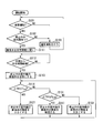
- FIG. 3 is a flowchart illustrating an example of a processing procedure in which the air conditioning operation control device 100 controls the air conditioning system main body 200.
- the air-conditioning operation control apparatus 100 starts the process of FIG. 3 when the power supply of the air-conditioning system 1 is connected (ON) and the operation is started. Note that when the power of the air conditioning system 1 is turned off (OFF), the air conditioning operation control device 100 ends the process of FIG.
- the operation mode determination unit 191 determines whether or not the air conditioning system main body 200 is in the heating operation (step S101). If it is determined that the heating operation is being performed (step S101: YES), the stop determination unit 192 determines whether there is a stopped indoor unit 210 (step S102). If it is determined that there is a stopped indoor unit 210 (step S102: YES), the expansion valve control unit 193 opens the opening of the expansion valve 222 connected to the stopped indoor unit 210 to a predetermined opening. (Step S111).
- the expansion valve control unit 193 opens the opening degree of the expansion valve 222 connected to all the stopped indoor units 210 to a predetermined opening degree.
- the expansion valve control unit 193 opens the opening of the expansion valve 222 connected to a part of the stopped indoor units 210 by a predetermined amount. It may be opened each time.
- the expansion valve control unit 193 determines whether or not a predetermined time has elapsed since the expansion valve 222 was opened in step S111 (step S112). For example, the expansion valve control unit 193 includes a timer, and measures an elapsed time after completing the opening degree adjustment of the expansion valve 222 in step S111. Then, the expansion valve control unit 193 determines whether or not the measurement time by the timer has reached a predetermined time.
- step S112 When it is determined that a predetermined time has not elapsed since the expansion valve 222 was opened (step S112: NO), the process returns to step S112. That is, it waits for the passage of a predetermined time. On the other hand, when it is determined that a predetermined time has elapsed since opening the expansion valve 222 (step S112: YES), the expansion valve control unit 193 fully closes the expansion valve 222 opened in step S111 (step S113). .
- the expansion valve control unit 193 determines that the difference obtained by subtracting the temperature measurement value by the outdoor heat exchanger temperature sensor 312 from the temperature measurement value by the compressor suction side temperature sensor 311 is a predetermined threshold T LOW. It is determined whether it is below (step S114).
- the difference obtained by subtracting the temperature measurement value by the outdoor heat exchanger temperature sensor 312 from the temperature measurement value by the compressor suction side temperature sensor 311 will be expressed as ⁇ TSH.
- the threshold value T LOW is a threshold value set in advance as a lower limit value of the allowable range of ⁇ TSH.
- step S114 When it is determined that ⁇ TSH is equal to or less than the threshold T LOW (step S114: YES), the expansion valve control unit 193 is connected to the stopped indoor unit 210 (the indoor unit 210 whose opening degree is adjusted in step S111).
- the opening degree of the expansion valve 222 is reduced (step S121).
- the expansion valve 222 is an electronic expansion valve, the valve is closed by a predetermined number of pulses. That is, when it is determined that ⁇ TSH is smaller than the lower limit value of the allowable range, the expansion valve control unit 193 reduces the opening of the expansion valve 222 connected to the stopped indoor unit 210 to reduce the inside of the indoor unit 210.
- step S121 the process returns to step S114.
- step S114 determines whether ⁇ TSH is equal to or less than a predetermined threshold value T HIGH (step S131).
- the threshold value T HIGH is a threshold value set in advance as an upper limit value of the allowable range of ⁇ TSH, and “T HIGH > T LOW ” is satisfied.
- step S31 When it is determined that ⁇ TSH is equal to or less than the threshold value T HIGH (step S31: YES), the expansion valve control unit 193 is connected to the stopped indoor unit 210 (the indoor unit 210 whose opening degree is adjusted in step S111).
- the opening degree of the expansion valve 222 is maintained (step S141). That is, when it is determined that ⁇ TSH is within the allowable range, the expansion valve control unit 193 maintains the opening of the expansion valve 222 connected to the stopped indoor unit 210 to store the refrigerant in the indoor unit 210. Let the amount of maintain. Thereby, the quantity of the refrigerant
- step S131 when it is determined in step S131 that ⁇ TSH is larger than the threshold value T HIGH (step S131: NO), the expansion valve control unit 193 determines that the indoor unit 210 is stopped (the indoor unit 210 whose opening is adjusted in step S111). ) Is increased (step S151).
- the expansion valve 222 is an electronic expansion valve, the valve is opened by a predetermined number of pulses. That is, when it is determined that ⁇ TSH is larger than the upper limit value of the allowable range, the expansion valve control unit 193 increases the opening of the expansion valve 222 connected to the stopped indoor unit 210, thereby increasing the inside of the indoor unit 210. Reduce the amount of refrigerant stored in Thereby, the quantity of the refrigerant
- step S101 determines whether the heating operation is not being performed.
- step S102 determines whether the heating operation is not being performed.
- step S161 the air conditioning system main body 200 performs a normal operation according to the control of the air conditioning operation control device 100.
- step S161 the air conditioning system 1 does not perform processing for storing the refrigerant in the stopped indoor unit 210.
- step S102: NO the process transitions to step S161.
- step S161 the process returns to step S101 from the state where the air conditioning system main body 200 is operating normally.
- the control unit 190 periodically transitions to step S101.
- the control unit 190 may transition to step S101. . If a user operation for switching the operation mode of the air conditioning system 1 or a user operation for operating the stopped indoor unit 210 is performed in any of steps S111 to S151, the process proceeds to step S101 in an interrupt process. Transition.
- the expansion valve control unit 193 controls the opening of the expansion valve 222 based on the measured value of the compressor suction side temperature sensor 311 and the measured value of the outdoor heat exchanger temperature sensor 312.
- the compressor outlet temperature sensor 313, the compressor outlet pressure sensor 314, and the indoor heat exchanger temperature sensor 315 are not essential for the process of storing the refrigerant in the stopped indoor unit 210.
- the measured value that is referred to when the expansion valve control unit 193 controls the opening degree of the expansion valve 222 connected to the stopped indoor unit 210 is the measured value of the compressor suction side temperature sensor 311 and the outdoor heat exchange. It is not restricted to the measured value of the vessel temperature sensor 312.
- the expansion valve control unit 193 may control the opening degree of the expansion valve 222 connected to the stopped indoor unit 210 based on the measured value of the compressor outlet temperature sensor 313. Specifically, in step S114, the expansion valve control unit 193 may determine whether or not the measured value of the compressor outlet temperature sensor 313 is equal to or lower than the compressor outlet temperature lower limit threshold value.
- the compressor outlet temperature lower limit threshold is a threshold set in advance as the outlet temperature lower limit of the compressor 226.
- expansion valve control part 193 judges whether the measured value of compressor outlet temperature sensor 313 is below the compressor outlet temperature upper limit threshold.
- the compressor outlet temperature upper limit threshold is a threshold predetermined as the outlet temperature upper limit of the compressor 226. In this case, regarding the process of storing the refrigerant in the stopped indoor unit 210, the compressor suction side temperature sensor 311, the outdoor heat exchanger temperature sensor 312, the compressor outlet pressure sensor 314, and the indoor heat exchanger temperature sensor 315 are: Not required.
- the expansion valve control unit 193 determines the opening degree of the expansion valve 222 connected to the stopped indoor unit 210 based on the measured value of the compressor outlet temperature sensor 313 and the measured value of the compressor outlet pressure sensor 314. You may make it control. For example, in step S114, the expansion valve control unit 193 may determine whether the measured value of the compressor outlet temperature sensor 313 is equal to or lower than the compressor outlet temperature lower limit threshold and equal to or lower than the compressor outlet pressure lower limit threshold. Good.
- the compressor outlet pressure lower limit threshold is a threshold predetermined as the outlet pressure lower limit of the compressor 226.
- expansion valve control part 193 judges whether the measured value of compressor outlet temperature sensor 313 is below the compressor outlet temperature upper limit threshold and below the compressor outlet pressure upper limit threshold.
- the compressor outlet pressure upper limit threshold value is a threshold value determined in advance as the outlet pressure upper limit value of the compressor 226.
- the compressor suction side temperature sensor 311, the outdoor heat exchanger temperature sensor 312, and the indoor heat exchanger temperature sensor 315 are not essential for the process of storing the refrigerant in the stopped indoor unit 210.
- the expansion valve control unit 193 determines the opening degree of the expansion valve 222 connected to the stopped indoor unit 210 based on the measured value of the outdoor heat exchanger temperature sensor 312 and the measured value of the compressor outlet temperature sensor 313. You may make it control. For example, whether or not the difference obtained by subtracting the measured value of the outdoor heat exchanger temperature sensor 312 from the measured value of the compressor outlet temperature sensor 313 from the measured value of the compressor outlet temperature sensor 313 in step S114 is equal to or smaller than a predetermined lower limit threshold value. You may make it determine.
- step S131 the expansion valve control unit 193 determines whether or not the difference obtained by subtracting the measured value of the outdoor heat exchanger temperature sensor 312 from the measured value of the compressor outlet temperature sensor 313 is equal to or less than a predetermined upper limit threshold value. Determine whether.
- the compressor suction side temperature sensor 311, the compressor outlet pressure sensor 314, and the indoor heat exchanger temperature sensor 315 are not essential for the process of storing the refrigerant in the stopped indoor unit 210.
- the expansion valve control unit 193 changes the opening of the expansion valve 222 connected to the stopped indoor unit 210 to the measured value of the outdoor heat exchanger temperature sensor 312 and the measured value of the indoor heat exchanger temperature sensor 315. You may make it control based on. For example, in step S114, the expansion valve control unit 193 determines whether the difference obtained by subtracting the measured value of the outdoor heat exchanger temperature sensor 312 from the measured value of the indoor heat exchanger temperature sensor 315 is equal to or less than a predetermined lower limit threshold value. It may be determined whether or not. Specifically, the expansion valve control unit 193 calculates the average value of the measured values of the indoor heat exchanger temperature sensor 315 provided in the operating indoor unit 210, and the outdoor heat exchanger from the obtained average value.
- the measured value of the temperature sensor 312 is subtracted. And the expansion valve control part 193 determines whether the difference obtained by subtraction is below a predetermined
- the compressor suction side temperature sensor 311, the compressor outlet temperature sensor 313, and the compressor outlet pressure sensor 314 are not essential for the process of storing the refrigerant in the stopped indoor unit 210.
- the operation mode determination unit 191 determines whether or not the air conditioning system main body 200 is in the heating operation.
- the stop determination unit 192 determines whether there is a stopped indoor unit 210.
- the expansion valve control unit 193 opens the expansion valve 222 connected to the stopped indoor unit 210, and then performs the expansion. The valve 222 is closed. Accordingly, the stopped indoor unit 210 can store the refrigerant, and the amount of the refrigerant flowing into the compressor 226 can be reduced.
- the expansion valve control unit 193 controls the expansion valve 222, so that the stopped indoor unit 210 can store the refrigerant. It is only necessary to provide the expansion valve 222 on the outlet side during the heating operation of the indoor heat exchanger 211, and it is not necessary to provide the expansion valve on the inlet side, so that the configuration of the air conditioning system 1 can be made relatively simple. . In addition, it is not necessary to provide a capillary for returning the refrigerant to the compressor suction side pipe on the outlet side during the heating operation of the indoor heat exchanger 211, and since the stopped indoor unit 210 stores the refrigerant, There is no need to provide a separate receiver tank for storing the water. Also in this respect, the configuration of the air conditioning system 1 can be relatively simplified.
- the expansion valve control unit 193 can change the amount of refrigerant flowing through the refrigerant circuit by changing the opening degree of the expansion valve 222. If the expansion valve control unit 193 changes the opening degree of the expansion valve 222, it is considered that the amount of refrigerant flowing through the refrigerant circuit is changed immediately, and the responsiveness is high.
- the expansion valve control unit 193 opens the expansion valve 222 connected to the stopped indoor unit 210 to a predetermined opening degree, and opens the expansion valve 222 to a predetermined opening degree.
- the expansion valve 222 is fully closed after a predetermined time has elapsed. Accordingly, the expansion valve control unit 193 can store the refrigerant in the stopped indoor unit 210 by a simple process of opening the expansion valve 222 to a predetermined opening degree and then fully closing the expansion valve 222.
- the expansion valve control unit 193 closes the expansion valve 222 connected to the stopped indoor unit 210, and then opens the expansion valve 222 based on the temperature of the refrigerant flowing through the refrigerant circuit of the air conditioning system main body 200. To control. Accordingly, the expansion valve control unit 193 can detect that the amount of refrigerant flowing through the refrigerant circuit is decreased and the efficiency of heat exchange is reduced, and can increase the amount of refrigerant flowing through the refrigerant circuit. Further, the expansion valve control unit 193 detects that the amount of refrigerant flowing through the refrigerant circuit has increased and the amount of refrigerant flowing into the compressor 226 has increased, and reduces the amount of refrigerant flowing through the refrigerant circuit. Can do.
- the expansion valve control unit 193 determines the expansion valve 222 based on the difference between the temperature of the refrigerant flowing into the compressor 226 and the temperature of the refrigerant discharged from the compressor 226 compressor and flowing into the outdoor heat exchanger 223. To control the opening degree. Thereby, the expansion valve control part 193 can control the opening degree of the expansion valve 222 based on the result of the simple calculation of calculating the difference of the temperature measurement value by the sensor. For example, the expansion valve control unit 193 compares the difference obtained by subtracting the temperature measurement value by the outdoor heat exchanger temperature sensor 312 from the temperature measurement value by the compressor suction side temperature sensor 311 with the threshold value, and compares the result. Based on this, the opening degree of the expansion valve 222 can be controlled.
- the expansion valve control unit 193 may control the opening degree of the expansion valve 222 based on the temperature of the refrigerant discharged from the compressor 226. Thereby, the expansion valve control part 193 can control the opening degree of the expansion valve 222 based on the result of the simple calculation using the temperature measurement value by the sensor. For example, the expansion valve control unit 193 can control the opening degree of the expansion valve 222 based on the result of a simple calculation of comparing the temperature measurement value by the compressor outlet temperature sensor 313 with a threshold value.
- a program for realizing all or part of the functions of the control unit 190 is recorded on a computer-readable recording medium, and the program recorded on the recording medium is read into a computer system and executed. You may perform the process of.
- the “computer system” here includes an OS and hardware such as peripheral devices.
- the “computer-readable recording medium” refers to a storage device such as a flexible medium, a magneto-optical disk, a portable medium such as a ROM or a CD-ROM, and a hard disk incorporated in a computer system.
- the program may be a program for realizing a part of the functions described above, and may be a program capable of realizing the functions described above in combination with a program already recorded in a computer system.
- the air conditioning system can be configured more simply and the amount of refrigerant flowing into the compressor can be reduced.
- Air conditioning system 100 Air-conditioning operation control apparatus 110 Measurement value acquisition part 180 Storage part 190 Control part 191 Operation mode determination part 192 Stop determination part 193 Expansion valve control part
Landscapes
- Engineering & Computer Science (AREA)
- Mechanical Engineering (AREA)
- General Engineering & Computer Science (AREA)
- Chemical & Material Sciences (AREA)
- Combustion & Propulsion (AREA)
- Physics & Mathematics (AREA)
- Thermal Sciences (AREA)
- Air Conditioning Control Device (AREA)
- Compression-Type Refrigeration Machines With Reversible Cycles (AREA)
Abstract
空調運転制御装置は、1つの室外機と、複数の室内機と、前記複数の室内機それぞれの暖房時の冷媒出口側に1つずつ設けられた複数の膨張弁とを備えた冷媒回路を備えた空調システム本体が暖房運転中か否かを判定する運転モード判定部と、前記空調システム本体が暖房運転中であると前記運転モード判定部が判定した場合、複数の前記室内機のうち停止している室内機が存在するか否かを判定する停止判定部と、停止している前記室内機が存在すると前記停止判定部が判定した場合、停止している前記室内機に接続された膨張弁を開いた状態にした後、当該膨張弁を閉じる膨張弁制御部と、を備える。
Description
本発明は、空調運転制御装置、空調システム、空調運転制御方法及びプログラムに関する。
本願は、2016年3月25日に、日本に出願された特願2016-62595号に基づき優先権を主張し、その内容をここに援用する。
本願は、2016年3月25日に、日本に出願された特願2016-62595号に基づき優先権を主張し、その内容をここに援用する。
1台の室外機と複数の室内機とを備えるマルチ型の空調システムでは、一部の室内機を停止している状態で暖房運転を行った場合に、圧縮機に流入する冷媒の量が増加し、圧縮機の潤滑油が冷媒で稀釈されることがある。潤滑油が稀釈されると圧縮機の運転の安定性に影響する可能性がある。
これに対し、特許文献1に記載の多室形空気調和機は、停止中の室内機に冷媒を流入させることで、圧縮機に流入する冷媒の量を減少させる。この多室形空気調和機では、2つの室内熱交換器それぞれの出入口の冷媒配管に電磁弁が設けられている。また、冷房時に室内熱交換器への入口側となる冷房時入口側電磁弁と室内熱交換器との間には、絞り機構と逆止弁とが並列に設けられている。更に、冷房時入口側電磁弁と絞り機構及び逆止弁との間には、冷媒を圧縮機吸入側配管に戻すキャピラリが設けられている。
そして、特許文献1に記載の多室形空気調和機は、暖房運転時に、運転中の室内熱交換器については出入口共に電磁弁を開く。一方、停止中の室内熱交換器については、冷房時入口側電磁弁のみを開く。特許文献1によれば、この状態で、停止中の室内熱交換器の内部は、キャピラリによって圧縮機低圧側に引かれて低圧になっており、充分な量の余剰冷媒を溜めることができるとされている。
特許文献1に記載の多室形空気調和機では、室内熱交換器の出入口両側の冷媒配管に電磁弁を設け、冷房時入口側電磁弁と室内熱交換器との間に、絞り機構、逆止弁及びキャピラリを設けるという構成が必要になる。より簡単な構成にすることができれば、装置の製造コストを低減させることができる。
本発明は、空調システムをより簡単な構成とすることができ、かつ、圧縮機に流入する冷媒の量を低減させることができる空調運転制御装置、空調システム、空調運転制御方法及びプログラムを提供する。
本発明の第1の態様によれば、空調運転制御装置は、1つの室外機と、複数の室内機と、前記複数の室内機それぞれの暖房時の冷媒出口側に1つずつ設けられた複数の膨張弁とを備えた冷媒回路を備えた空調システム本体が暖房運転中か否かを判定する運転モード判定部と、前記空調システム本体が暖房運転中であると前記運転モード判定部が判定した場合、複数の前記室内機のうち停止している室内機が存在するか否かを判定する停止判定部と、停止している前記室内機が存在すると前記停止判定部が判定した場合、停止している前記室内機に接続された膨張弁を開いた状態にした後、当該膨張弁を閉じる膨張弁制御部と、を備える。
前記膨張弁制御部は、停止している前記室内機に接続された膨張弁を所定の開度に開いた状態にし、当該膨張弁を所定の開度に開いた状態にしてから所定時間経過後に当該膨張弁を全閉するようにしてもよい。
前記膨張弁制御部は、停止している前記室内機に接続された前記膨張弁を閉じた後、前記冷媒回路を流れる冷媒の温度に基づいて当該膨張弁の開度を制御するようにしてもよい。
前記膨張弁制御部は、前記圧縮機に流入する前記冷媒の温度と、前記圧縮機から吐出されて前記室外機に設けられた室外熱交換器に流入した前記冷媒の温度との差に基づいて、前記膨張弁の開度を制御するようにしてもよい。
前記膨張弁制御部は、前記圧縮機から吐出された前記冷媒の温度に基づいて、前記膨張弁の開度を制御するようにしてもよい。
本発明の第2の態様によれば、空調システムは、1つの室外機と、複数の室内機と、前記複数の室内機それぞれの暖房時の冷媒出口側に1つずつ設けられた複数の膨張弁とを備えた冷媒回路を備えた空調システム本体と、前記したいずれかの空調運転制御装置とを備える。
本発明の第3の態様によれば、空調運転制御方法は、1つの室外機と、複数の室内機と、前記複数の室内機それぞれの暖房時の冷媒出口側に1つずつ設けられた複数の膨張弁とを備えた冷媒回路を備えた空調システム本体が暖房運転中か否かを判定する工程と、前記空調システム本体が暖房運転中であると判定した場合、複数の前記室内機のうち停止している室内機が存在するか否かを判定する工程と、停止している前記室内機が存在すると判定した場合、停止している前記室内機に接続された膨張弁を開状態にする工程と、開状態にした前記膨張弁を閉じる膨張弁制御部と、を含む。
本発明の第4の態様によれば、プログラムは、コンピュータに、1つの室外機と、複数の室内機と、前記複数の室内機それぞれの暖房時の冷媒出口側に1つずつ設けられた複数の膨張弁とを備えた冷媒回路を備えた空調システム本体が暖房運転中か否かを判定する工程と、前記空調システム本体が暖房運転中であると判定した場合、複数の前記室内機のうち停止している室内機が存在するか否かを判定する工程と、停止している前記室内機が存在すると判定した場合、停止している前記室内機に接続された膨張弁を開状態にする工程と、開状態にした前記膨張弁を閉じる工程と、を実行させるためのプログラムである。
上記した空調運転制御装置、空調システム、空調運転制御方法及びプログラムによれば、空調システムをより簡単な構成とすることができ、かつ、圧縮機に流入する冷媒の量を低減させることができる。
以下、本発明の実施形態を説明するが、以下の実施形態は請求の範囲にかかる発明を限定するものではない。また、実施形態の中で説明されている特徴の組み合わせの全てが発明の解決手段に必須であるとは限らない。
図1は、本発明の一実施形態に係る空調システムの装置構成を示す概略構成図である。
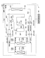
図1に示すように、空調システム(空気調和システム、Air Conditioning System)1は、空調運転制御装置100と、第一室内機210aと、第二室内機210bと、室外機220とを備える。第一室内機210aは、第一室内熱交換器211aと、第一室内熱交換器温度センサ315aとを備える。第二室内機210bは、第二室内熱交換器211bと、第二室内熱交換器温度センサ315bとを備える。室外機220は、膨張弁側第一サービスバルブ221aと、膨張弁側第二サービスバルブ221bと、第一膨張弁222aと、第二膨張弁222bと、室外熱交換器223と、四方弁224と、アキュムレータ225と、圧縮機226と、四方弁側第一サービスバルブ227aと、四方弁側第二サービスバルブ227bと、圧縮機吸入側温度センサ311と、室外熱交換器温度センサ312と、圧縮機出口温度センサ313と、圧縮機出口圧力センサ314とを備える。
図1は、本発明の一実施形態に係る空調システムの装置構成を示す概略構成図である。
図1に示すように、空調システム(空気調和システム、Air Conditioning System)1は、空調運転制御装置100と、第一室内機210aと、第二室内機210bと、室外機220とを備える。第一室内機210aは、第一室内熱交換器211aと、第一室内熱交換器温度センサ315aとを備える。第二室内機210bは、第二室内熱交換器211bと、第二室内熱交換器温度センサ315bとを備える。室外機220は、膨張弁側第一サービスバルブ221aと、膨張弁側第二サービスバルブ221bと、第一膨張弁222aと、第二膨張弁222bと、室外熱交換器223と、四方弁224と、アキュムレータ225と、圧縮機226と、四方弁側第一サービスバルブ227aと、四方弁側第二サービスバルブ227bと、圧縮機吸入側温度センサ311と、室外熱交換器温度センサ312と、圧縮機出口温度センサ313と、圧縮機出口圧力センサ314とを備える。
第一室内機210aと、第二室内機210bとを総称して室内機210と表記する。第一室内熱交換器211aと、第二室内熱交換器211bとを総称して室内熱交換器211と表記する。第一室内熱交換器温度センサ315aと第二室内熱交換器温度センサ315bとを総称して室内熱交換器温度センサ315と表記する。膨張弁側第一サービスバルブ221aと、膨張弁側第二サービスバルブ221bとを総称して膨張弁側サービスバルブ221と表記する。第一膨張弁222aと、第二膨張弁222bを総称して膨張弁222と表記する。四方弁側第一サービスバルブ227aと、四方弁側第二サービスバルブ227bとを総称して四方弁側サービスバルブ227と表記する。
また、空調システム1のうち、空調運転制御装置100以外の各部を総称して空調システム本体200と表記する。
また、空調システム1のうち、空調運転制御装置100以外の各部を総称して空調システム本体200と表記する。
第一室内機210aと膨張弁側第一サービスバルブ221aとは第一室内機側第一配管W11aで接続されている。第二室内機210bと膨張弁側第二サービスバルブ221bとは第二室内機側第一配管W11bで接続されている。膨張弁側第一サービスバルブ221aと第一膨張弁222aとは第一室内機側第二配管W12aで接続されている。膨張弁側第二サービスバルブ221bと第二膨張弁222bとは第二室内機側第二配管W12bで接続されている。第一膨張弁222a及び第二膨張弁222bの各々と室外熱交換器223とは第三配管W13で接続されている。室外熱交換器223と四方弁224とは第四配管W14で接続されている。四方弁224とアキュムレータ225とは第五配管W15で接続されている。アキュムレータ225と圧縮機226とは第六配管W16及び第七配管W17で接続されている。気体の冷媒が第六配管W16を通る。また、圧縮機226で液体になった冷媒は第七配管W17を通ってアキュムレータ225に貯められる。圧縮機226と四方弁224とは第八配管W18で接続されている。四方弁224と四方弁側第一サービスバルブ227a及び四方弁側第二サービスバルブ227bの各々とは第九配管W19で接続されている。四方弁側第一サービスバルブ227aと第一室内機210aとは第一室内機側第十配管W20aで接続されている。四方弁側第二サービスバルブ227bと第二室内機210bとは第二室内機側第十配管W20bで接続されている。
第一室内機側第一配管W11aと第二室内機側第一配管W11bとを総称して第一配管W11と表記する。また、第一室内機側第二配管W12aと第二室内機側第二配管W12bとを総称して第二配管W12と表記する。第一室内機側第十配管W20aと第二室内機側第十配管W20bとを総称して第十配管W20と表記する。
空調システム1が備える室内機210の数は図1に示す2つに限らず3つ以上であってもよい。その場合も、室内機210の各々が室内熱交換器211を1つずつ備える。そして、室外機220は、室内機210と同数の膨張弁側サービスバルブ221、膨張弁222及び四方弁側サービスバルブ227を備える。室内熱交換器211と、膨張弁側サービスバルブ221とが第一配管W11で一対一に接続される。膨張弁側サービスバルブ221と膨張弁222とが第二配管W12で一対一に接続される。膨張弁222の各々と室外熱交換器223とが第三配管W13で接続される。四方弁224と四方弁側サービスバルブ227の各々とが第九配管W19で接続される。四方弁側サービスバルブ227と室内機210とが第十配管W20で一対一に接続される。
空調システム1は、室内の空気の温度を調整するシステムである。特に、空調システム1は、室内機210が設置された各部屋の空気の温度を調整するなど、複数の室内機210を備えることで比較的広い範囲の空気の温度を調整する。
空調システム1では、暖房運転と冷房運転とを切り替え可能である。
暖房運転では、圧縮機226で圧縮された気体の冷媒が、第八配管W18、四方弁224、第九配管W19、四方弁側サービスバルブ227、第十配管W20の順に経由して室内熱交換器211へ流入する。室内熱交換器211へ流入した気体の冷媒は、室内の空気との熱交換によって放熱して凝縮する。凝縮によって液体になった冷媒は、第一配管W11、膨張弁側サービスバルブ221、第二配管W12を経由して膨張弁222で減圧された後、第三配管W13を経由して室外熱交換器223へ流入する。
このように、膨張弁222は、複数の室内熱交換器211それぞれの暖房時の冷媒出口側に1つずつ設けられている。すなわち、膨張弁222は、複数の室内機210それぞれの暖房時の冷媒出口側に1つずつ設けられている。
室外熱交換器223へ流入した冷媒は、外気(室外の空気)との熱交換によって吸熱して蒸発する。蒸発によって気体になった冷媒は、第四配管W14、四方弁224、第五配管W15、アキュムレータ225、第六配管W16の順に経由して圧縮機226へ流入し圧縮される。このように、空調システム本体200が備える装置が配管で接続されて冷媒が循環する冷媒回路を構成する。以下、空調システム1の暖房運転、空調システム1の冷房運転を、それぞれ空調システム本体200の暖房運転、空調システム本体200の冷房運転とも称する。
なお、第七配管W17は、圧縮機226に流入又は発生した液体の冷媒をアキュムレータ225へ流入させるための配管である。
なお、第七配管W17は、圧縮機226に流入又は発生した液体の冷媒をアキュムレータ225へ流入させるための配管である。
空調システム本体200は、空調運転制御装置100の制御を受けて動作し、室内の空気の温度を調整する。
室内機210は、温度調整対象の室内に設置される。
室内熱交換器211は、冷媒と室内の空気との間で熱交換を行わせる。暖房運転では、高圧の気体の冷媒が室内熱交換器211へ流入し、室内の空気との熱交換によって放熱して凝縮する。従って、室内熱交換器211は、圧縮機226によって圧縮された気体の冷媒を液化させて凝縮熱を室内の空気に放熱する。
室内機210は、温度調整対象の室内に設置される。
室内熱交換器211は、冷媒と室内の空気との間で熱交換を行わせる。暖房運転では、高圧の気体の冷媒が室内熱交換器211へ流入し、室内の空気との熱交換によって放熱して凝縮する。従って、室内熱交換器211は、圧縮機226によって圧縮された気体の冷媒を液化させて凝縮熱を室内の空気に放熱する。
室外機220は、例えば室外など外気との熱交換が可能な場所に設置される。
膨張弁側サービスバルブ221及び四方弁側サービスバルブ227は、いずれも室内機210の取り外し時などに冷媒を遮断するために用いられる。
膨張弁222は、膨張弁222自らを流れる液体の冷媒を減圧する。この減圧により冷媒が蒸発し易くなる。膨張弁222は調整弁として構成されている。膨張弁222の開度を調節することで、膨張弁222を流れる冷媒の流量を調節することができる。
膨張弁222としてパルス信号に応じて弁の開閉を行う電子膨張弦を用いるようにしてもよい。但し、膨張弁222の種類は電子膨張弁に限らず、膨張弁222は冷媒の流量を絞って減圧することができる調整弁であればよい。
膨張弁側サービスバルブ221及び四方弁側サービスバルブ227は、いずれも室内機210の取り外し時などに冷媒を遮断するために用いられる。
膨張弁222は、膨張弁222自らを流れる液体の冷媒を減圧する。この減圧により冷媒が蒸発し易くなる。膨張弁222は調整弁として構成されている。膨張弁222の開度を調節することで、膨張弁222を流れる冷媒の流量を調節することができる。
膨張弁222としてパルス信号に応じて弁の開閉を行う電子膨張弦を用いるようにしてもよい。但し、膨張弁222の種類は電子膨張弁に限らず、膨張弁222は冷媒の流量を絞って減圧することができる調整弁であればよい。
室外熱交換器223は、冷媒と外気との間で熱交換を行わせる。暖房運転では、膨張弁222で減圧された低圧の液体の冷媒が室外熱交換器223へ流入し、外気との熱交換によって吸熱して蒸発する。従って、室外熱交換器223は、外気から気化熱を吸熱して液体の冷媒を気化させる。
四方弁224は、冷媒の流路を切り替えることで暖房運転、冷房運転の切替を行う。暖房運転では四方弁224は、第八配管W18と第九配管W19とを接続することで圧縮機226からの冷媒を室内熱交換器211へ流入させる。また、暖房運転では四方弁224は、第四配管W14と第五配管W15とを接続することで室外熱交換器223からの冷媒を圧縮機226へ流入させる。
アキュムレータ225は、アキュムレータ225自らに流入する冷媒を液体の冷媒と気体の冷媒とに分離し、気体の冷媒のみを圧縮機226へ流入させる。圧縮機226へ液体の冷媒が流入して圧縮機226が故障することを回避するためである。
圧縮機226は、気体の冷媒を圧縮する。
アキュムレータ225は、アキュムレータ225自らに流入する冷媒を液体の冷媒と気体の冷媒とに分離し、気体の冷媒のみを圧縮機226へ流入させる。圧縮機226へ液体の冷媒が流入して圧縮機226が故障することを回避するためである。
圧縮機226は、気体の冷媒を圧縮する。
圧縮機吸入側温度センサ311は、圧縮機226の吸入側(低圧側)の冷媒の温度を測定する。例えば、圧縮機吸入側温度センサ311は、第五配管W15に設けられて四方弁224からアキュムレータ225を経由して圧縮機226へ流入する冷媒の温度を測定する。
室外熱交換器温度センサ312は、室外熱交換器223における冷媒の温度を測定する。例えば、室外熱交換器温度センサ312は第三配管W13に設けられ、暖房運転時に室外熱交換器223へ流入する冷媒の温度を測定する。
室外熱交換器温度センサ312は、室外熱交換器223における冷媒の温度を測定する。例えば、室外熱交換器温度センサ312は第三配管W13に設けられ、暖房運転時に室外熱交換器223へ流入する冷媒の温度を測定する。
圧縮機出口温度センサ313は、圧縮機226の出口側(高圧側)の冷媒の温度を測定する。例えば、圧縮機出口温度センサ313は第八配管W18に設けられ、圧縮機226から吐出された冷媒の温度を測定する。
圧縮機出口圧力センサ314は、圧縮機226で圧縮された冷媒の圧力を測定する。例えば、圧縮機出口圧力センサ314は第八配管W18に設けられ、圧縮機226から吐出された冷媒の圧力を測定する。
室内熱交換器温度センサ315の各々は、室内熱交換器211における冷媒の温度を測定する。例えば、室内熱交換器温度センサ315は、室内熱交換器211内の冷媒の配管に設けられ、室内熱交換器211で凝縮される前の冷媒の温度を測定する。
圧縮機出口圧力センサ314は、圧縮機226で圧縮された冷媒の圧力を測定する。例えば、圧縮機出口圧力センサ314は第八配管W18に設けられ、圧縮機226から吐出された冷媒の圧力を測定する。
室内熱交換器温度センサ315の各々は、室内熱交換器211における冷媒の温度を測定する。例えば、室内熱交換器温度センサ315は、室内熱交換器211内の冷媒の配管に設けられ、室内熱交換器211で凝縮される前の冷媒の温度を測定する。
空調運転制御装置100は、空調システム本体200を制御する。空調運転制御装置100は、例えばコンピュータを用いて構成される。
図2は、空調運転制御装置100の機能構成を示す概略ブロック図である。図2に示すように、空調運転制御装置100は、測定値取得部110と、記憶部180と、制御部190とを備える。制御部190は、運転モード判定部191と、停止判定部192と、膨張弁制御部193とを備える。
図2は、空調運転制御装置100の機能構成を示す概略ブロック図である。図2に示すように、空調運転制御装置100は、測定値取得部110と、記憶部180と、制御部190とを備える。制御部190は、運転モード判定部191と、停止判定部192と、膨張弁制御部193とを備える。
測定値取得部110は、空調システム本体200に設けられた各種センサによる測定値を取得する。測定値取得部110は、例えば空調運転制御装置100が備える通信回路を用いて構成される。
記憶部180は、各種データを記憶する。記憶部180は、例えば空調運転制御装置100が備える記憶デバイスを用いて構成される。
制御部190は、空調運転制御装置100の各部を制御することにより、空調システム本体200の制御を実行する。制御部190は、例えば空調運転制御装置100が備えるCPU(Central Processing Unit、中央処理装置)が記憶部180からプログラムを読み出して実行することで実現される。
記憶部180は、各種データを記憶する。記憶部180は、例えば空調運転制御装置100が備える記憶デバイスを用いて構成される。
制御部190は、空調運転制御装置100の各部を制御することにより、空調システム本体200の制御を実行する。制御部190は、例えば空調運転制御装置100が備えるCPU(Central Processing Unit、中央処理装置)が記憶部180からプログラムを読み出して実行することで実現される。
運転モード判定部191は、空調システム本体200の冷房回路の運転モード(すなわち、空調システム1の運転モード)を判定する。ここでいう運転モードは暖房運転、冷房運転の区別である。特に、運転モード判定部191は、空調システム本体200が暖房運転中か否かを判定する。
停止判定部192は、空調システム本体200が暖房運転中であると運転モード判定部191が判定した場合、複数の室内機210のうち停止している室内機210が存在するか否かを判定する。
ここでいう停止している室内機210は、ユーザによって停止操作が行われた室内機210である。停止している室内機210では、送風ファンが停止され、暖気又は冷気の送出が停止される。なお、停止している室内機210を停止中の室内機210とも称する。
停止判定部192は、空調システム本体200が暖房運転中であると運転モード判定部191が判定した場合、複数の室内機210のうち停止している室内機210が存在するか否かを判定する。
ここでいう停止している室内機210は、ユーザによって停止操作が行われた室内機210である。停止している室内機210では、送風ファンが停止され、暖気又は冷気の送出が停止される。なお、停止している室内機210を停止中の室内機210とも称する。
膨張弁制御部193は、膨張弁222の開度を制御する。特に、停止している室内機210が存在すると停止判定部192が判定した場合、膨張弁222は、停止している室内機210に接続された膨張弁222を開いた状態にした後、当該膨張弁222を閉じる。
例えば、膨張弁制御部193は、停止している室内機210に接続された膨張弁222を所定の開度に開いた状態にする。あるいは、膨張弁制御部193が、この膨張弁222を全開にするようにしてもよい。
そして、膨張弁制御部193は、当該膨張弁222を所定の開度に開いた状態にしてから所定時間経過後に当該膨張弁222を全閉する。あるいは、膨張弁制御部193が、この膨張弁222を所定の開度まで閉じるようにしてもよい。
例えば、膨張弁制御部193は、停止している室内機210に接続された膨張弁222を所定の開度に開いた状態にする。あるいは、膨張弁制御部193が、この膨張弁222を全開にするようにしてもよい。
そして、膨張弁制御部193は、当該膨張弁222を所定の開度に開いた状態にしてから所定時間経過後に当該膨張弁222を全閉する。あるいは、膨張弁制御部193が、この膨張弁222を所定の開度まで閉じるようにしてもよい。
なお、膨張弁制御部193が膨張弁222を閉じるタイミングは、当該膨張弁222を所定の開度に開いた状態にしてから所定時間経過後に限らない。例えば、空調システム1の運転開始から所定時間経過後に、膨張弁制御部193が膨張弁222を閉じるようにしてもよい。あるいは、室内熱交換器211内の冷媒圧力が所定の圧力以上になったタイミングで、膨張弁制御部193が膨張弁222を閉じるようにしてもよい。
膨張弁222が停止している室内機210に接続された膨張弁222を開いた状態にすることで、この室内機210の室内熱交換器211に、圧縮機226によって圧縮された高密度の冷媒を流入させることができる。その後、膨張弁222がこの室内機210に接続された膨張弁222を閉じることで、この室内機210の室内熱交換器211内に高密度の冷媒を溜めておくことができる。これにより、空調システム本体200の冷媒回路を流れる冷媒の量を減少させることができ、圧縮機226に流入する冷媒の量を減少させることができる。
膨張弁制御部193は、停止している室内機210に接続された膨張弁222を閉じた後、圧縮機226で圧縮された後の冷媒の温度に基づいて当該膨張弁222の開度を制御する。
ここで、圧縮機226で圧縮された後の冷媒の温度が高い場合、冷媒回路を流れる冷媒の量が不足して熱交換の効率が低下している可能性がある。そこで、膨張弁制御部193は、膨張弁222の開度を大きくして冷媒回路を流れる冷媒の量を増加させる。これにより、熱交換の効率が改善されることが期待される。
ここで、圧縮機226で圧縮された後の冷媒の温度が高い場合、冷媒回路を流れる冷媒の量が不足して熱交換の効率が低下している可能性がある。そこで、膨張弁制御部193は、膨張弁222の開度を大きくして冷媒回路を流れる冷媒の量を増加させる。これにより、熱交換の効率が改善されることが期待される。
一方、圧縮機226で圧縮された後の冷媒の温度が低い場合、冷媒回路を流れる冷媒の量が多く、圧縮機226に流入する冷媒の量も多い可能性がある。圧縮機226に流入する冷媒の量が多いと、圧縮機226の潤滑油が冷媒で稀釈され、圧縮機226の運転の安定性に影響する可能性がある。そこで、膨張弁制御部193は、膨張弁222の開度を小さくして冷媒回路を流れる冷媒の量を減少させる。これにより、圧縮機226に流入する冷媒の量を減少させることができ、圧縮機226の潤滑油が冷媒で稀釈されて圧縮機226の運転の安定性に影響することを回避できる。
次に、図3を参照して空調システム1の動作について説明する。
図3は、空調運転制御装置100が空調システム本体200を制御する処理手順の例を示すフローチャートである。空調運転制御装置100は、空調システム1の電源が接続(ON)されて運転を開始すると図3の処理を開始する。なお、空調システム1の電源が切断(OFF)されると、空調運転制御装置100は図3の処理を終了する。
図3は、空調運転制御装置100が空調システム本体200を制御する処理手順の例を示すフローチャートである。空調運転制御装置100は、空調システム1の電源が接続(ON)されて運転を開始すると図3の処理を開始する。なお、空調システム1の電源が切断(OFF)されると、空調運転制御装置100は図3の処理を終了する。
図3の処理で、運転モード判定部191は、空調システム本体200が暖房運転中か否かを判定する(ステップS101)。
暖房運転中であると判定した場合(ステップS101:YES)、停止判定部192は、停止中の室内機210が有るか否かを判定する(ステップS102)。
停止中の室内機210が有ると判定した場合(ステップS102:YES)、膨張弁制御部193は、停止中の室内機210に接続されている膨張弁222の開度を所定の開度に開く(ステップS111)。
暖房運転中であると判定した場合(ステップS101:YES)、停止判定部192は、停止中の室内機210が有るか否かを判定する(ステップS102)。
停止中の室内機210が有ると判定した場合(ステップS102:YES)、膨張弁制御部193は、停止中の室内機210に接続されている膨張弁222の開度を所定の開度に開く(ステップS111)。
なお、空調システム1が室内機210を3つ以上備えている場合、停止中の室内機210が複数ある場合がある。この場合、膨張弁制御部193は、停止中の全ての室内機210に接続されている膨張弁222の開度を所定の開度に開く。あるいは、室内機210の各々が冷媒を蓄える容量が十分多い場合、膨張弁制御部193が、停止中の室内機210のうちの一部に接続されている膨張弁222の開度を所定の開度に開くようにしてもよい。
ステップS111の後、膨張弁制御部193は、ステップS111で膨張弁222を開いてから所定の時間が経過したか否かを判定する(ステップS112)。例えば、膨張弁制御部193はタイマを備え、ステップS111での膨張弁222の開度調整を完了してからの経過時間を測定する。そして、膨張弁制御部193は、タイマでの測定時間が所定の時間に到達したか否かを判定する。
膨張弁222を開いてから所定の時間が経過していないと判定した場合(ステップS112:NO)、処理がステップS112へ戻る。すなわち、所定時間の経過を待ち受ける。
一方、膨張弁222を開いてから所定の時間が経過したと判定した場合(ステップS112:YES)、膨張弁制御部193は、ステップS111で開いた膨張弁222を全閉にする(ステップS113)。
一方、膨張弁222を開いてから所定の時間が経過したと判定した場合(ステップS112:YES)、膨張弁制御部193は、ステップS111で開いた膨張弁222を全閉にする(ステップS113)。
ステップS113の後、膨張弁制御部193は、圧縮機吸入側温度センサ311による温度測定値から室外熱交換器温度センサ312による温度測定値を減算することにより得られた差が所定の閾値TLOW以下か否かを判定する(ステップS114)。
以下では、圧縮機吸入側温度センサ311による温度測定値から室外熱交換器温度センサ312による温度測定値を減算することにより得られた差をΔTSHと表記する。閾値TLOWは、ΔTSHの許容範囲の下限値として予め設定されている閾値である。
以下では、圧縮機吸入側温度センサ311による温度測定値から室外熱交換器温度センサ312による温度測定値を減算することにより得られた差をΔTSHと表記する。閾値TLOWは、ΔTSHの許容範囲の下限値として予め設定されている閾値である。
ΔTSHが閾値TLOW以下であると判定した場合(ステップS114:YES)、膨張弁制御部193は、停止中の室内機210(ステップS111で開度を調整した室内機210)に接続されている膨張弁222の開度を小さくする(ステップS121)。例えば、この膨張弁222が電子膨張弁である場合、所定数のパルスの分だけ弁を閉じる。
すなわち、ΔTSHが許容範囲の下限値よりも小さいと判定した場合、膨張弁制御部193は、停止中の室内機210に接続されている膨張弁222の開度を小さくすることで室内機210内に蓄える冷媒の量を増加させる。これにより、空調システム本体200の冷媒回路を流れる冷媒の量が減少する。特に、圧縮機226へ流入する冷媒の量が減少する。
ステップS121の後、処理がステップS114へ戻る。
すなわち、ΔTSHが許容範囲の下限値よりも小さいと判定した場合、膨張弁制御部193は、停止中の室内機210に接続されている膨張弁222の開度を小さくすることで室内機210内に蓄える冷媒の量を増加させる。これにより、空調システム本体200の冷媒回路を流れる冷媒の量が減少する。特に、圧縮機226へ流入する冷媒の量が減少する。
ステップS121の後、処理がステップS114へ戻る。
一方、ステップS114で、ΔTSHが閾値TLOWよりも大きいと判定した場合(ステップS114:NO)、膨張弁222は、ΔTSHが所定の閾値THIGH以下か否かを判定する(ステップS131)。閾値THIGHは、ΔTSHの許容範囲の上限値として予め設定されている閾値であり、「THIGH>TLOW」が満たされる。
ΔTSHが閾値THIGH以下であると判定した場合(ステップS31:YES)、膨張弁制御部193は、停止中の室内機210(ステップS111で開度を調整した室内機210)に接続されている膨張弁222の開度を維持する(ステップS141)。
すなわち、ΔTSHが許容範囲内にあると判定した場合、膨張弁制御部193は、停止中の室内機210に接続されている膨張弁222の開度を維持することで室内機210内に蓄える冷媒の量を維持させる。これにより、空調システム本体200の冷媒回路を流れる冷媒の量も維持される。
ステップS141の後、処理がステップS114へ戻る。
すなわち、ΔTSHが許容範囲内にあると判定した場合、膨張弁制御部193は、停止中の室内機210に接続されている膨張弁222の開度を維持することで室内機210内に蓄える冷媒の量を維持させる。これにより、空調システム本体200の冷媒回路を流れる冷媒の量も維持される。
ステップS141の後、処理がステップS114へ戻る。
一方、ステップS131で、ΔTSHが閾値THIGHよりも大きいと判定した場合(ステップS131:NO)、膨張弁制御部193は、停止中の室内機210(ステップS111で開度を調整した室内機210)に接続されている膨張弁222の開度を大きくする(ステップS151)。例えば、この膨張弁222が電子膨張弁である場合、所定数のパルスの分だけ弁を開く。
すなわち、ΔTSHが許容範囲の上限値よりも大きいと判定した場合、膨張弁制御部193は、停止中の室内機210に接続されている膨張弁222の開度を大きくすることで室内機210内に蓄える冷媒の量を減少させる。これにより、空調システム本体200の冷媒回路を流れる冷媒の量が増加する。
ステップS151の後、処理がステップS114へ戻る。
すなわち、ΔTSHが許容範囲の上限値よりも大きいと判定した場合、膨張弁制御部193は、停止中の室内機210に接続されている膨張弁222の開度を大きくすることで室内機210内に蓄える冷媒の量を減少させる。これにより、空調システム本体200の冷媒回路を流れる冷媒の量が増加する。
ステップS151の後、処理がステップS114へ戻る。
一方、ステップS101で暖房運転中ではないと判定した場合(ステップS101:NO)、空調システム本体200は、空調運転制御装置100の制御に従って通常運転を行う(ステップS161)。この通常運転では、空調システム1は、冷媒を停止中の室内機210に溜めておくための処理を行わない。
ステップS102で停止中の室内機210が無いと判定した場合も(ステップS102:NO)、処理がステップS161へ遷移する。
ステップS102で停止中の室内機210が無いと判定した場合も(ステップS102:NO)、処理がステップS161へ遷移する。
ステップS161で空調システム本体200が通常運転を行っている状態から、処理がステップS101へ戻る。例えば、空調システム本体200が通常運転を行っている場合に、制御部190は定期的にステップS101へ遷移する。あるいは、空調システム1の運転モードを切り替えるユーザ操作が行われる毎、及び、室内機210のいずれかを停止させるユーザ操作が行われる毎に、制御部190がステップS101へ遷移するようにしてもよい。
なお、ステップS111~S151のいずれかで、空調システム1の運転モードを切り替えるユーザ操作、又は、停止中の室内機210を運転させるユーザ操作が行われた場合、割込み処理にて処理がステップS101へ遷移する。
なお、ステップS111~S151のいずれかで、空調システム1の運転モードを切り替えるユーザ操作、又は、停止中の室内機210を運転させるユーザ操作が行われた場合、割込み処理にて処理がステップS101へ遷移する。
なお、上述したステップS114及びS131のように、膨張弁制御部193が圧縮機吸入側温度センサ311の測定値及び室外熱交換器温度センサ312の測定値に基づいて膨張弁222の開度を制御する場合、停止中の室内機210に冷媒を溜めておく処理に関しては、圧縮機出口温度センサ313、圧縮機出口圧力センサ314及び室内熱交換器温度センサ315は必須ではない。
一方、膨張弁制御部193が停止中の室内機210に接続されている膨張弁222の開度を制御する際に参照する測定値は、圧縮機吸入側温度センサ311の測定値及び室外熱交換器温度センサ312の測定値に限らない。
一方、膨張弁制御部193が停止中の室内機210に接続されている膨張弁222の開度を制御する際に参照する測定値は、圧縮機吸入側温度センサ311の測定値及び室外熱交換器温度センサ312の測定値に限らない。
例えば、膨張弁制御部193が、停止中の室内機210に接続されている膨張弁222の開度を圧縮機出口温度センサ313の測定値に基づいて制御するようにしてもよい。具体的には、ステップS114で、膨張弁制御部193が、圧縮機出口温度センサ313の測定値が圧縮機出口温度下限閾値以下か否かを判定するようにしてもよい。ここで、圧縮機出口温度下限閾値は、圧縮機226の出口温度下限値として予め定められている閾値である。また、ステップS131では、膨張弁制御部193は、圧縮機出口温度センサ313の測定値が、圧縮機出口温度上限閾値以下か否かを判定する。ここで、圧縮機出口温度上限閾値は、圧縮機226の出口温度上限値として予め定められている閾値である。
この場合、停止中の室内機210に冷媒を溜めておく処理に関しては、圧縮機吸入側温度センサ311、室外熱交換器温度センサ312、圧縮機出口圧力センサ314及び室内熱交換器温度センサ315は必須ではない。
この場合、停止中の室内機210に冷媒を溜めておく処理に関しては、圧縮機吸入側温度センサ311、室外熱交換器温度センサ312、圧縮機出口圧力センサ314及び室内熱交換器温度センサ315は必須ではない。
あるいは、膨張弁制御部193が、停止中の室内機210に接続されている膨張弁222の開度を圧縮機出口温度センサ313の測定値と圧縮機出口圧力センサ314の測定値とに基づいて制御するようにしてもよい。例えば、ステップS114で、膨張弁制御部193が、圧縮機出口温度センサ313の測定値が圧縮機出口温度下限閾値以下、かつ、圧縮機出口圧力下限閾値以下か否かを判定するようにしてもよい。ここで、圧縮機出口圧力下限閾値は、圧縮機226の出口圧力下限値として予め定められている閾値である。また、ステップS131では、膨張弁制御部193は、圧縮機出口温度センサ313の測定値が圧縮機出口温度上限閾値以下、かつ、圧縮機出口圧力上限閾値以下か否かを判定する。ここで、圧縮機出口圧力上限閾値は、圧縮機226の出口圧力上限値として予め定められている閾値である。
この場合、停止中の室内機210に冷媒を溜めておく処理に関しては、圧縮機吸入側温度センサ311、室外熱交換器温度センサ312及び室内熱交換器温度センサ315は必須ではない。
この場合、停止中の室内機210に冷媒を溜めておく処理に関しては、圧縮機吸入側温度センサ311、室外熱交換器温度センサ312及び室内熱交換器温度センサ315は必須ではない。
あるいは、膨張弁制御部193が、停止中の室内機210に接続されている膨張弁222の開度を室外熱交換器温度センサ312の測定値と圧縮機出口温度センサ313の測定値とに基づいて制御するようにしてもよい。例えば、ステップS114で、膨張弁制御部193が、圧縮機出口温度センサ313の測定値から室外熱交換器温度センサ312の測定値を減算することにより得られた差が所定の下限閾値以下か否かを判定するようにしてもよい。また、ステップS131では、膨張弁制御部193は、圧縮機出口温度センサ313の測定値から室外熱交換器温度センサ312の測定値を減算することにより得られた差が所定の上限閾値以下か否かを判定する。
この場合、停止中の室内機210に冷媒を溜めておく処理に関しては、圧縮機吸入側温度センサ311、圧縮機出口圧力センサ314及び室内熱交換器温度センサ315は必須ではない。
この場合、停止中の室内機210に冷媒を溜めておく処理に関しては、圧縮機吸入側温度センサ311、圧縮機出口圧力センサ314及び室内熱交換器温度センサ315は必須ではない。
あるいは、膨張弁制御部193が、停止中の室内機210に接続されている膨張弁222の開度を室外熱交換器温度センサ312の測定値と室内熱交換器温度センサ315の測定値とに基づいて制御するようにしてもよい。例えば、ステップS114で、膨張弁制御部193が、室内熱交換器温度センサ315の測定値から室外熱交換器温度センサ312の測定値を減算することにより得られた差が所定の下限閾値以下か否かを判定するようにしてもよい。具体的には、膨張弁制御部193は、運転中の室内機210に設けられている室内熱交換器温度センサ315の測定値の平均値を算出し、得られた平均値から室外熱交換器温度センサ312の測定値を減算する。そして、膨張弁制御部193は、減算にて得られた差が所定の下限閾値以下か否かを判定する。また、ステップS131では、膨張弁制御部193は、減算にて得られた差が所定の上限閾値以下か否かを判定する。
この場合、停止中の室内機210に冷媒を溜めておく処理に関しては、圧縮機吸入側温度センサ311、圧縮機出口温度センサ313及び圧縮機出口圧力センサ314は必須ではない。
この場合、停止中の室内機210に冷媒を溜めておく処理に関しては、圧縮機吸入側温度センサ311、圧縮機出口温度センサ313及び圧縮機出口圧力センサ314は必須ではない。
以上のように、運転モード判定部191は、空調システム本体200が暖房運転中か否かを判定する。そして、空調システム本体200が暖房運転中であると運転モード判定部191が判定した場合、停止判定部192は、停止している室内機210が存在するか否かを判定する。停止している室内機210が存在すると停止判定部192が判定した場合、膨張弁制御部193は、停止している室内機210に接続された膨張弁222を開いた状態にした後、当該膨張弁222を閉じる。
これにより、停止中の室内機210が冷媒を溜めておくことができ、圧縮機226に流入する冷媒の量を低減させることができる。また、膨張弁制御部193が膨張弁222を制御することで、停止中の室内機210が冷媒を溜めておくようにすることができる。室内熱交換器211の暖房運転時の出口側に膨張弁222を設ければよく、入口側には膨張弁を設ける必要がない点で、空調システム1の構成を比較的簡単にすることができる。また、室内熱交換器211の暖房運転時の出口側に冷媒を圧縮機吸入側配管に戻すキャピラリを設ける必要がない点でも、また、停止中の室内機210が冷媒を溜めておくので、冷媒を溜めておくためのレシーバタンクを別途設ける必要がない。この点でも、空調システム1の構成を比較的簡単にすることができる。
また、膨張弁制御部193が膨張弁222の開度を変化させることで冷媒回路を流れる冷媒の量を変化させることができる。膨張弁制御部193が膨張弁222の開度を変化させれば直ちに冷媒回路を流れる冷媒の量を変化すると考えられ、応答性が高い。
例えば、膨張弁制御部193は、停止している室内機210に接続された膨張弁222を所定の開度に開いた状態にし、当該膨張弁222を所定の開度に開いた状態にしてから所定時間経過後に当該膨張弁222を全閉する。
これにより、膨張弁制御部193は、膨張弁222を所定の開度に開いた後に全閉するという簡単な処理で、停止中の室内機210に冷媒を蓄えさせることができる。
これにより、膨張弁制御部193は、膨張弁222を所定の開度に開いた後に全閉するという簡単な処理で、停止中の室内機210に冷媒を蓄えさせることができる。
また、膨張弁制御部193は、停止している室内機210に接続された膨張弁222を閉じた後、空調システム本体200の冷媒回路を流れる冷媒の温度に基づいて当該膨張弁222の開度を制御する。
これにより、膨張弁制御部193は、冷媒回路を流れる冷媒の量が減少して熱交換の効率が低下していることを検知し、冷媒回路を流れる冷媒の量を増加させることができる。
また、膨張弁制御部193は、冷媒回路を流れる冷媒の量が増加して圧縮機226に流入する冷媒の量が増加していることを検知し、冷媒回路を流れる冷媒の量を減少させることができる。
これにより、膨張弁制御部193は、冷媒回路を流れる冷媒の量が減少して熱交換の効率が低下していることを検知し、冷媒回路を流れる冷媒の量を増加させることができる。
また、膨張弁制御部193は、冷媒回路を流れる冷媒の量が増加して圧縮機226に流入する冷媒の量が増加していることを検知し、冷媒回路を流れる冷媒の量を減少させることができる。
例えば、膨張弁制御部193は、圧縮機226に流入する冷媒の温度と、圧縮機226圧縮機から吐出されて室外熱交換器223に流入した冷媒の温度との差に基づいて、膨張弁222の開度を制御する。
これにより、膨張弁制御部193は、センサによる温度測定値の差を算出するという簡単な演算の結果に基づいて、膨張弁222の開度を制御することができる。例えば、膨張弁制御部193は、圧縮機吸入側温度センサ311による温度測定値から室外熱交換器温度センサ312による温度測定値を減算することにより得られた差と閾値とを比較し、比較結果に基づいて膨張弁222の開度を制御することができる。
これにより、膨張弁制御部193は、センサによる温度測定値の差を算出するという簡単な演算の結果に基づいて、膨張弁222の開度を制御することができる。例えば、膨張弁制御部193は、圧縮機吸入側温度センサ311による温度測定値から室外熱交換器温度センサ312による温度測定値を減算することにより得られた差と閾値とを比較し、比較結果に基づいて膨張弁222の開度を制御することができる。
あるいは、膨張弁制御部193が、圧縮機226から吐出された冷媒の温度に基づいて膨張弁222の開度を制御するようにしてもよい。
これにより、膨張弁制御部193は、センサによる温度測定値を用いた簡単な演算の結果に基づいて、膨張弁222の開度を制御することができる。例えば、膨張弁制御部193は、圧縮機出口温度センサ313による温度測定値と閾値とを比較するという簡単な演算の結果に基づいて、膨張弁222の開度を制御することができる。
これにより、膨張弁制御部193は、センサによる温度測定値を用いた簡単な演算の結果に基づいて、膨張弁222の開度を制御することができる。例えば、膨張弁制御部193は、圧縮機出口温度センサ313による温度測定値と閾値とを比較するという簡単な演算の結果に基づいて、膨張弁222の開度を制御することができる。
なお、制御部190の全部または一部の機能を実現するためのプログラムをコンピュータ読み取り可能な記録媒体に記録して、この記録媒体に記録されたプログラムをコンピュータシステムに読み込ませ、実行することにより各部の処理を行ってもよい。なお、ここでいう「コンピュータシステム」とは、OSや周辺機器等のハードウェアを含む。
また、「コンピュータ読み取り可能な記録媒体」とは、フレキシブルディスク、光磁気ディスク、ROM、CD-ROM等の可搬媒体、コンピュータシステムに内蔵されるハードディスク等の記憶装置のことをいう。また上記プログラムは、前述した機能の一部を実現するためのものであっても良く、さらに前述した機能をコンピュータシステムにすでに記録されているプログラムとの組み合わせで実現できるものであってもよい。
また、「コンピュータ読み取り可能な記録媒体」とは、フレキシブルディスク、光磁気ディスク、ROM、CD-ROM等の可搬媒体、コンピュータシステムに内蔵されるハードディスク等の記憶装置のことをいう。また上記プログラムは、前述した機能の一部を実現するためのものであっても良く、さらに前述した機能をコンピュータシステムにすでに記録されているプログラムとの組み合わせで実現できるものであってもよい。
以上、本発明の実施形態について図面を参照して詳述してきたが、具体的な構成はこの実施形態に限られるものではなく、この発明の要旨を逸脱しない範囲の設計変更等も含まれる。
上記した空調運転制御装置、空調システム、空調運転制御方法及びプログラムによれば、空調システムをより簡単な構成とすることができ、かつ、圧縮機に流入する冷媒の量を低減させることができる。
1 空調システム
100 空調運転制御装置
110 測定値取得部
180 記憶部
190 制御部
191 運転モード判定部
192 停止判定部
193 膨張弁制御部
100 空調運転制御装置
110 測定値取得部
180 記憶部
190 制御部
191 運転モード判定部
192 停止判定部
193 膨張弁制御部
Claims (8)
- 1つの室外機と、複数の室内機と、前記複数の室内機それぞれの暖房時の冷媒出口側に1つずつ設けられた複数の膨張弁とを備えた冷媒回路を備えた空調システム本体が暖房運転中か否かを判定する運転モード判定部と、
前記空調システム本体が暖房運転中であると前記運転モード判定部が判定した場合、複数の前記室内機のうち停止している室内機が存在するか否かを判定する停止判定部と、
停止している前記室内機が存在すると前記停止判定部が判定した場合、停止している前記室内機に接続された膨張弁を開いた状態にした後、当該膨張弁を閉じる膨張弁制御部と、
を備える空調運転制御装置。 - 前記膨張弁制御部は、停止している前記室内機に接続された膨張弁を所定の開度に開いた状態にし、当該膨張弁を所定の開度に開いた状態にしてから所定時間経過後に当該膨張弁を全閉する、請求項1に記載の空調運転制御装置。
- 前記膨張弁制御部は、停止している前記室内機に接続された前記膨張弁を閉じた後、前記冷媒回路を流れる冷媒の温度に基づいて当該膨張弁の開度を制御する、請求項1または請求項2に記載の空調運転制御装置。
- 前記膨張弁制御部は、前記冷媒回路に設けられた圧縮機に流入する前記冷媒の温度と、前記圧縮機から吐出されて前記室外機に設けられた室外熱交換器に流入した前記冷媒の温度との差に基づいて、前記膨張弁の開度を制御する、請求項3に記載の空調運転制御装置。
- 前記膨張弁制御部は、前記冷媒回路に設けられた圧縮機から吐出された前記冷媒の温度に基づいて、前記膨張弁の開度を制御する、請求項3に記載の空調運転制御装置。
- 1つの室外機と、複数の室内機と、前記複数の室内機それぞれの暖房時の冷媒出口側に1つずつ設けられた複数の膨張弁とを備えた冷媒回路を備えた空調システム本体と、請求項1から5のいずれか一項に記載の空調運転制御装置とを備える空調システム。
- 1つの室外機と、複数の室内機と、前記複数の室内機それぞれの暖房時の冷媒出口側に1つずつ設けられた複数の膨張弁とを備えた冷媒回路を備えた空調システム本体が暖房運転中か否かを判定する工程と、
前記空調システム本体が暖房運転中であると判定した場合、複数の前記室内機のうち停止している室内機が存在するか否かを判定する工程と、
停止している前記室内機が存在すると判定した場合、停止している前記室内機に接続された膨張弁を開状態にする工程と、
開状態にした前記膨張弁を閉じる膨張弁制御部と、
を含む空調運転制御方法。 - コンピュータに、
1つの室外機と、複数の室内機と、前記複数の室内機それぞれの暖房時の冷媒出口側に1つずつ設けられた複数の膨張弁とを備えた冷媒回路を備えた空調システム本体が暖房運転中か否かを判定する工程と、
前記空調システム本体が暖房運転中であると判定した場合、複数の前記室内機のうち停止している室内機が存在するか否かを判定する工程と、
停止している前記室内機が存在すると判定した場合、停止している前記室内機に接続された膨張弁を開状態にする工程と、
開状態にした前記膨張弁を閉じる工程と、
を実行させるためのプログラム。
Priority Applications (2)
| Application Number | Priority Date | Filing Date | Title |
|---|---|---|---|
| CN201780004243.4A CN108291748A (zh) | 2016-03-25 | 2017-03-21 | 空调运行控制装置、空调系统、空调运行控制方法及程序 |
| EP17770194.3A EP3379170A4 (en) | 2016-03-25 | 2017-03-21 | Air conditioning operation control device, air conditioning system, air conditioning control method, and program |
Applications Claiming Priority (2)
| Application Number | Priority Date | Filing Date | Title |
|---|---|---|---|
| JP2016-062595 | 2016-03-25 | ||
| JP2016062595A JP2017172946A (ja) | 2016-03-25 | 2016-03-25 | 空調運転制御装置、空調システム、空調運転制御方法及びプログラム |
Publications (1)
| Publication Number | Publication Date |
|---|---|
| WO2017164152A1 true WO2017164152A1 (ja) | 2017-09-28 |
Family
ID=59899428
Family Applications (1)
| Application Number | Title | Priority Date | Filing Date |
|---|---|---|---|
| PCT/JP2017/011138 WO2017164152A1 (ja) | 2016-03-25 | 2017-03-21 | 空調運転制御装置、空調システム、空調運転制御方法及びプログラム |
Country Status (4)
| Country | Link |
|---|---|
| EP (1) | EP3379170A4 (ja) |
| JP (1) | JP2017172946A (ja) |
| CN (1) | CN108291748A (ja) |
| WO (1) | WO2017164152A1 (ja) |
Cited By (1)
| Publication number | Priority date | Publication date | Assignee | Title |
|---|---|---|---|---|
| EP3483524A1 (en) * | 2017-11-09 | 2019-05-15 | Mitsubishi Heavy Industries Thermal Systems, Ltd. | Control device of multiple-type air conditioning device, multiple-type air conditioning device, method of controlling multiple-type air conditioning device, and computer program of controlling multiple-type air conditioning device |
Families Citing this family (2)
| Publication number | Priority date | Publication date | Assignee | Title |
|---|---|---|---|---|
| JP6886902B2 (ja) | 2017-09-08 | 2021-06-16 | シチズン時計株式会社 | 電子時計のムーブメント及び電子時計 |
| CN114353249B (zh) * | 2021-12-09 | 2023-07-18 | 青岛海尔空调电子有限公司 | 用于多联机空调的控制方法及装置、多联机空调 |
Citations (10)
| Publication number | Priority date | Publication date | Assignee | Title |
|---|---|---|---|---|
| JPS63233259A (ja) * | 1987-03-20 | 1988-09-28 | 株式会社日立製作所 | 多室形空気調和装置 |
| JPS6475860A (en) * | 1987-09-11 | 1989-03-22 | Matsushita Refrigeration | Multiple chamber type air conditioner |
| JPS6479553A (en) * | 1987-09-18 | 1989-03-24 | Matsushita Refrigeration | Multiple chamber type air conditioner |
| JPH01139964A (ja) | 1987-11-27 | 1989-06-01 | Hitachi Ltd | 多室形空気調和機 |
| JPH04359764A (ja) * | 1991-06-06 | 1992-12-14 | Toshiba Corp | 冷媒加熱式マルチ冷凍サイクル |
| JPH06323673A (ja) * | 1993-05-19 | 1994-11-25 | Hitachi Ltd | 多室型空気調和機 |
| JPH07324835A (ja) * | 1994-06-01 | 1995-12-12 | Mitsubishi Heavy Ind Ltd | マルチタイプ空気調和機 |
| JPH08114359A (ja) * | 1994-10-15 | 1996-05-07 | Mitsubishi Heavy Ind Ltd | 空気調和機 |
| JP2005351552A (ja) * | 2004-06-10 | 2005-12-22 | Mitsubishi Heavy Ind Ltd | 空気調和機 |
| JP2008145044A (ja) * | 2006-12-08 | 2008-06-26 | Daikin Ind Ltd | 空気調和装置 |
Family Cites Families (4)
| Publication number | Priority date | Publication date | Assignee | Title |
|---|---|---|---|---|
| JP4013981B2 (ja) * | 2006-02-17 | 2007-11-28 | 三菱電機株式会社 | 冷凍空調装置 |
| WO2012172599A1 (ja) * | 2011-06-14 | 2012-12-20 | 三菱電機株式会社 | 空気調和装置 |
| EP2889559B1 (en) * | 2012-08-03 | 2018-05-23 | Mitsubishi Electric Corporation | Air-conditioning device |
| CN105157171B (zh) * | 2015-08-28 | 2018-01-02 | 珠海格力电器股份有限公司 | 空调系统的控制方法和控制系统 |
-
2016
- 2016-03-25 JP JP2016062595A patent/JP2017172946A/ja active Pending
-
2017
- 2017-03-21 EP EP17770194.3A patent/EP3379170A4/en not_active Withdrawn
- 2017-03-21 CN CN201780004243.4A patent/CN108291748A/zh active Pending
- 2017-03-21 WO PCT/JP2017/011138 patent/WO2017164152A1/ja active Application Filing
Patent Citations (10)
| Publication number | Priority date | Publication date | Assignee | Title |
|---|---|---|---|---|
| JPS63233259A (ja) * | 1987-03-20 | 1988-09-28 | 株式会社日立製作所 | 多室形空気調和装置 |
| JPS6475860A (en) * | 1987-09-11 | 1989-03-22 | Matsushita Refrigeration | Multiple chamber type air conditioner |
| JPS6479553A (en) * | 1987-09-18 | 1989-03-24 | Matsushita Refrigeration | Multiple chamber type air conditioner |
| JPH01139964A (ja) | 1987-11-27 | 1989-06-01 | Hitachi Ltd | 多室形空気調和機 |
| JPH04359764A (ja) * | 1991-06-06 | 1992-12-14 | Toshiba Corp | 冷媒加熱式マルチ冷凍サイクル |
| JPH06323673A (ja) * | 1993-05-19 | 1994-11-25 | Hitachi Ltd | 多室型空気調和機 |
| JPH07324835A (ja) * | 1994-06-01 | 1995-12-12 | Mitsubishi Heavy Ind Ltd | マルチタイプ空気調和機 |
| JPH08114359A (ja) * | 1994-10-15 | 1996-05-07 | Mitsubishi Heavy Ind Ltd | 空気調和機 |
| JP2005351552A (ja) * | 2004-06-10 | 2005-12-22 | Mitsubishi Heavy Ind Ltd | 空気調和機 |
| JP2008145044A (ja) * | 2006-12-08 | 2008-06-26 | Daikin Ind Ltd | 空気調和装置 |
Non-Patent Citations (1)
| Title |
|---|
| See also references of EP3379170A4 * |
Cited By (1)
| Publication number | Priority date | Publication date | Assignee | Title |
|---|---|---|---|---|
| EP3483524A1 (en) * | 2017-11-09 | 2019-05-15 | Mitsubishi Heavy Industries Thermal Systems, Ltd. | Control device of multiple-type air conditioning device, multiple-type air conditioning device, method of controlling multiple-type air conditioning device, and computer program of controlling multiple-type air conditioning device |
Also Published As
| Publication number | Publication date |
|---|---|
| EP3379170A4 (en) | 2018-12-05 |
| CN108291748A (zh) | 2018-07-17 |
| EP3379170A1 (en) | 2018-09-26 |
| JP2017172946A (ja) | 2017-09-28 |
Similar Documents
| Publication | Publication Date | Title |
|---|---|---|
| US10345021B2 (en) | Active refrigerant charge compensation for refrigeration and air conditioning systems | |
| US9151522B2 (en) | Air conditioner and control method thereof | |
| CN107076475B (zh) | 用于运行具有接收器的蒸气压缩系统的方法 | |
| US20110154834A1 (en) | Air conditioner and method for controlling the same | |
| JP5402027B2 (ja) | 空気調和機 | |
| US8783050B2 (en) | Heat source unit | |
| JP6187514B2 (ja) | 冷凍装置 | |
| US11149999B2 (en) | Refrigeration cycle apparatus having foreign substance release control | |
| AU2002332260B2 (en) | Air conditioner | |
| JP6545252B2 (ja) | 冷凍サイクル装置 | |
| JP2007315702A (ja) | 冷凍装置 | |
| JP2007255750A (ja) | 冷凍装置 | |
| WO2017164152A1 (ja) | 空調運転制御装置、空調システム、空調運転制御方法及びプログラム | |
| JP7069298B2 (ja) | 空気調和装置 | |
| JP6577264B2 (ja) | 空調調和機 | |
| JP2006300371A (ja) | 空気調和機 | |
| CN112443947B (zh) | 同时冷暖多联机空调系统的控制方法 | |
| CN110709648B (zh) | 空调装置 | |
| JP4179783B2 (ja) | 空気調和装置 | |
| WO2022029845A1 (ja) | 空気調和装置 | |
| JP7225001B2 (ja) | 空気調和機 | |
| JP7013990B2 (ja) | 車両用空調装置 | |
| CN113614469A (zh) | 空调装置 | |
| JP2009008346A (ja) | 冷凍装置 | |
| JPWO2020065766A1 (ja) | 空気調和装置 |
Legal Events
| Date | Code | Title | Description |
|---|---|---|---|
| WWE | Wipo information: entry into national phase |
Ref document number: 2017770194 Country of ref document: EP |
|
| ENP | Entry into the national phase |
Ref document number: 2017770194 Country of ref document: EP Effective date: 20180620 |
|
| NENP | Non-entry into the national phase |
Ref country code: DE |