WO2017163995A1 - 外部接続バスバー保持モジュールおよび電池接続モジュール - Google Patents
外部接続バスバー保持モジュールおよび電池接続モジュール Download PDFInfo
- Publication number
- WO2017163995A1 WO2017163995A1 PCT/JP2017/010088 JP2017010088W WO2017163995A1 WO 2017163995 A1 WO2017163995 A1 WO 2017163995A1 JP 2017010088 W JP2017010088 W JP 2017010088W WO 2017163995 A1 WO2017163995 A1 WO 2017163995A1
- Authority
- WO
- WIPO (PCT)
- Prior art keywords
- external connection
- protector
- bus bar
- storage element
- connection bus
- Prior art date
- Legal status (The legal status is an assumption and is not a legal conclusion. Google has not performed a legal analysis and makes no representation as to the accuracy of the status listed.)
- Ceased
Links
Images










Classifications
-
- H—ELECTRICITY
- H01—ELECTRIC ELEMENTS
- H01M—PROCESSES OR MEANS, e.g. BATTERIES, FOR THE DIRECT CONVERSION OF CHEMICAL ENERGY INTO ELECTRICAL ENERGY
- H01M50/00—Constructional details or processes of manufacture of the non-active parts of electrochemical cells other than fuel cells, e.g. hybrid cells
- H01M50/50—Current conducting connections for cells or batteries
-
- H—ELECTRICITY
- H01—ELECTRIC ELEMENTS
- H01M—PROCESSES OR MEANS, e.g. BATTERIES, FOR THE DIRECT CONVERSION OF CHEMICAL ENERGY INTO ELECTRICAL ENERGY
- H01M50/00—Constructional details or processes of manufacture of the non-active parts of electrochemical cells other than fuel cells, e.g. hybrid cells
- H01M50/20—Mountings; Secondary casings or frames; Racks, modules or packs; Suspension devices; Shock absorbers; Transport or carrying devices; Holders
- H01M50/204—Racks, modules or packs for multiple batteries or multiple cells
- H01M50/207—Racks, modules or packs for multiple batteries or multiple cells characterised by their shape
- H01M50/209—Racks, modules or packs for multiple batteries or multiple cells characterised by their shape adapted for prismatic or rectangular cells
-
- H—ELECTRICITY
- H01—ELECTRIC ELEMENTS
- H01M—PROCESSES OR MEANS, e.g. BATTERIES, FOR THE DIRECT CONVERSION OF CHEMICAL ENERGY INTO ELECTRICAL ENERGY
- H01M50/00—Constructional details or processes of manufacture of the non-active parts of electrochemical cells other than fuel cells, e.g. hybrid cells
- H01M50/20—Mountings; Secondary casings or frames; Racks, modules or packs; Suspension devices; Shock absorbers; Transport or carrying devices; Holders
- H01M50/271—Lids or covers for the racks or secondary casings
-
- H—ELECTRICITY
- H01—ELECTRIC ELEMENTS
- H01G—CAPACITORS; CAPACITORS, RECTIFIERS, DETECTORS, SWITCHING DEVICES, LIGHT-SENSITIVE OR TEMPERATURE-SENSITIVE DEVICES OF THE ELECTROLYTIC TYPE
- H01G11/00—Hybrid capacitors, i.e. capacitors having different positive and negative electrodes; Electric double-layer [EDL] capacitors; Processes for the manufacture thereof or of parts thereof
- H01G11/10—Multiple hybrid or EDL capacitors, e.g. arrays or modules
-
- H—ELECTRICITY
- H01—ELECTRIC ELEMENTS
- H01M—PROCESSES OR MEANS, e.g. BATTERIES, FOR THE DIRECT CONVERSION OF CHEMICAL ENERGY INTO ELECTRICAL ENERGY
- H01M50/00—Constructional details or processes of manufacture of the non-active parts of electrochemical cells other than fuel cells, e.g. hybrid cells
- H01M50/20—Mountings; Secondary casings or frames; Racks, modules or packs; Suspension devices; Shock absorbers; Transport or carrying devices; Holders
- H01M50/262—Mountings; Secondary casings or frames; Racks, modules or packs; Suspension devices; Shock absorbers; Transport or carrying devices; Holders with fastening means, e.g. locks
-
- Y—GENERAL TAGGING OF NEW TECHNOLOGICAL DEVELOPMENTS; GENERAL TAGGING OF CROSS-SECTIONAL TECHNOLOGIES SPANNING OVER SEVERAL SECTIONS OF THE IPC; TECHNICAL SUBJECTS COVERED BY FORMER USPC CROSS-REFERENCE ART COLLECTIONS [XRACs] AND DIGESTS
- Y02—TECHNOLOGIES OR APPLICATIONS FOR MITIGATION OR ADAPTATION AGAINST CLIMATE CHANGE
- Y02E—REDUCTION OF GREENHOUSE GAS [GHG] EMISSIONS, RELATED TO ENERGY GENERATION, TRANSMISSION OR DISTRIBUTION
- Y02E60/00—Enabling technologies; Technologies with a potential or indirect contribution to GHG emissions mitigation
- Y02E60/10—Energy storage using batteries
Definitions
- the technology disclosed in the present specification relates to an externally connected bus bar holding module and a battery connecting module including the holding module. Specifically, the technology is connected to a pair of output electrode terminals for outputting electric power to the outside of a storage element group.
- the present invention relates to an external connection bus bar holding module that holds an external connection bus bar.
- Patent Document 1 As an external connection bus bar connected to an output electrode terminal of a storage element group, for example, the one described in Patent Document 1 is known.
- a battery module (power storage module) M1 configured such that a pair of output electrode terminals are electrode terminals of power storage elements at both ends of a power storage element group
- an external connection connected to the electrode terminals of power storage elements at both ends A bus bar 19B is described.
- each external connection bus bar 19B is held by the resin protector 20 together with the bus bar 19 that connects the electrode terminals of the tree electricity storage element.
- the external connection bus bar is used.
- power is supplied from the power storage element group to the external device from the same end side of the power storage element group.
- two types of external connection bus bars having different shapes are required, and two types of external connection bus bar insulation protectors (holding modules) corresponding thereto are required.
- the technology disclosed in the present specification has been completed based on the above-described circumstances, and can cope with an arbitrary position of power extraction from the power storage element group, and can be easily attached to the power storage element group.
- An external connection bus bar holding module that can be provided, and a battery connection module including the holding module are provided.
- the externally connected busbar holding module disclosed in this specification is an externally connected busbar holding module that is attached to a power storage element group including a plurality of power storage elements having positive and negative electrode terminals, A first output electrode terminal that outputs electric power of the second polarity and a second output electrode terminal that outputs electric power of the other polarity, and the module includes a first electrode connecting portion connected to the first output electrode terminal A first external connection bus bar including a first external connection portion connected to an external device, an intermediate portion located between the first electrode connection portion and the first external connection portion, and the second output electrode terminal A second external connection bus bar including a second electrode connection portion connected to the external device, and a second external connection portion connected to the external device, and a first electrode connection portion holding the first electrode connection portion of the first external connection bus bar.
- first protector portion a first protector portion, a second protector portion that is disposed at a distance from the first protector portion and holds the first external connection portion of the first external connection bus bar, the first protector portion, and the second protector portion. And an intermediate protector portion that holds the intermediate portion of the first external connection bus bar between the first protector portion and the second protector portion.
- the externally connected bus bar holding module is configured by three protector parts, a first protector part, a second protector part, and an intermediate protector part. Therefore, for example, by making the length (shape) of the intermediate portion of the first external connection bus bar and the length (shape) of the intermediate protector portion correspond to the power extraction position of the storage element group, the external connection bus bar holding module is It can be made to correspond to the arbitrary position of the electric power extraction of an electrical storage element group. Further, the external connection bus bar holding module is integrated by combining the first protector part and the second protector part with the intermediate protector part. Therefore, it is possible to easily attach the external connection bus bar holding module to the power storage element group.
- the externally connected busbar holding module of this configuration it is possible to cope with an arbitrary position of the power storage element group for taking out electric power, and it can be easily attached to the power storage element group.
- the intermediate protector portion is formed separately from the first protector portion and the second protector portion, and one end portion of the intermediate protector portion is held by the first protector portion. The other end portion may be held by the second protector portion.
- the externally connected bus bar holding module is composed of three individual protector parts, a first protector part, a second protector part, and an intermediate protector part. Therefore, for example, when the length of the intermediate portion of the first external connection bus bar corresponds to the power extraction position of the power storage element group, the first protector portion and the second protector portion can be used as they are, and the length of the intermediate protector portion is simply used. This can be done simply by changing the design.
- the intermediate protector portion may be made of an extruded synthetic resin. According to this configuration, since the intermediate protector portion is formed by extrusion molding, only one mold is required when forming the intermediate protector portion regardless of the length of the intermediate protector portion. Further, the length of the intermediate protector portion can be easily changed according to the number of power storage elements in the power storage element group. That is, by changing the length of only the intermediate protector among the three protectors of the first protector, the second protector, and the intermediate protector, it is possible to cope with various power storage elements having different numbers of power storage elements. . Therefore, when the external connection bus bar holding module is made to correspond to various power storage element groups, it is not necessary to create a separate mold separately, and the cost can be reduced.
- the intermediate protector portion is formed integrally with the first protector portion or the second protector portion, and one end portion of the intermediate protector portion is not integrated. You may make it hold
- the intermediate protector portion may be formed integrally with the first protector portion and the second protector portion. According to this configuration, the intermediate protector unit is integrated with the first protector unit and the second protector unit. Therefore, the configuration for holding the first external connection bus bar can be further simplified, and the configuration as the external connection bus bar holding module can be further simplified.
- the first output electrode terminal is configured by an electrode terminal having one polarity of a power storage element located at one end of the power storage element group in an arrangement direction of the plurality of power storage elements.
- the two output electrode terminals are configured by electrode terminals of the other polarity of the power storage elements located at the other end in the arrangement direction of the plurality of power storage elements in the power storage element group, and the intermediate portion of the first external connection bus bar is
- the first protector may have a shape extending from the first electrode connecting part to the first external connecting part, and the second protector part may hold the second external connecting bus bar.
- the first external connection bus bar is connected to the first external connection bus bar.
- the position of the connection portion and the position of the second external connection portion of the second external connection bus bar are the other end side (the same one end side) in the arrangement direction of the plurality of power storage elements in the power storage element group. Therefore, in the case where the first output electrode terminal and the second output electrode terminal are arranged apart from both ends of the storage element group, the power extraction position of the storage element group is determined in the arrangement direction of the plurality of storage elements in the storage element group. Any one end side can be easily and accurately realized.
- the battery connection module disclosed in this specification is a battery connection module attached to an upper part of the power storage element group, and the external connection busbar holding module according to any one of the above, and the power storage element adjacent to the battery connection module.
- a plurality of bus bars connecting the positive electrode terminal and the negative electrode terminal; and an insulation protector holding the plurality of bus bars; and the external connection bus bar holding module is disposed above the insulation protector.
- the battery connection module can correspond to an arbitrary position for taking out electric power from the power storage element group, and can be easily attached to the power storage element group. .
- the battery connection module further includes a cover that covers at least the first external connection bus bar excluding the first external connection portion, the second external connection bus bar excluding the second external connection portion, and the plurality of bus bars. You may do it.
- the battery connection module includes the first external connection bus bar excluding the first external connection portion, the second external connection bus bar excluding the second external connection portion, and the cover that covers the bus bar. Therefore, it is possible to prevent two adjacent bus bars or the first external connection bus bar and the second external connection bus bar from being short-circuited by an external metal or the like. Moreover, it can suppress that dust etc. penetrate
- FIG. 6 is a plan view of a power storage module according to the second embodiment.
- FIG. 18 is a plan view excluding each external connection bus bar. Sectional view along the line DD in FIG.
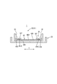
- FIG. 3 is a cross-sectional view taken along the line AA in FIG.
- the power storage module 100 shown in the present embodiment is mounted on a vehicle (not shown) such as an electric vehicle or a hybrid vehicle and used as a power source for driving the vehicle.
- the external connection bus bar holding module 1 shown in the present embodiment is attached to the upper part of the power storage module 100 (see FIG. 4).
- the direction indicated by the arrow X in FIGS. 1 and 4 will be described as the left side, and the direction indicated by the arrow Y in FIG.
- symbol may be attached
- the externally connected busbar holding module 1 includes a first protector unit 10, a second protector unit 20, an intermediate protector unit 30, a negative electrode external connection bus bar 40, and a positive electrode external connection.
- a bus bar 50 is provided.
- the negative electrode external connection bus bar 40 is connected to the negative electrode output terminal OUTN among the pair of output electrode terminals (OUTP, OUTN) for outputting electric power to the outside of the power storage element group 60 (see FIG. 4).
- the negative electrode external connection bus bar 40 has a thin plate shape (see FIG. 3). Specifically, the negative electrode external connection bus bar 40 is, as shown in FIG. 1, the first electrode connection part 40 ⁇ / b> A connected to the negative electrode output terminal OUTN of the power storage element group 60, and the external device supplied with power from the power storage element group 60.
- the first external connection portion 40B connected to the intermediate portion 40C and the intermediate portion 40C positioned between the first electrode connection portion 40A and the first external connection portion 40B.
- the negative electrode external connection bus bar 40 is an example of a “first external connection bus bar”.
- the intermediate portion 40C corresponds to, for example, a range indicated by an arrow W in FIG.
- the first electrode connection portion 40A corresponds to a portion on the left side of the intermediate portion 40C
- the first external connection portion 40B It corresponds to a portion on the right side of the intermediate portion 40C.
- the intermediate portion 40C has a shape extending from the first electrode connection portion 40A to the first external connection portion 40B.
- the first electrode connecting portion 40A a through hole 41 for connecting the negative external connection bus bar 40 to the negative output terminal OUTN is formed.
- the first external connection portion 40B is formed with a first connection terminal portion 42 for connecting the negative electrode external connection bus bar 40 to an external device.
- the positive electrode external connection bus bar 50 is connected to the second electrode connection part 50 ⁇ / b> A connected to the positive electrode output terminal OUTP of the power storage element group 60 and the external device to which power is supplied from the power storage element group 60.
- the second external connection part 50B is included.
- a through hole 51 for connecting the positive external connection bus bar 50 to the positive output terminal OUTP is formed in the second electrode connection portion 50A.
- the second external connection portion 50B is formed with a second connection terminal portion 52 for connecting the positive electrode external connection bus bar 50 to an external device.
- the positive external connection bus bar 50 is an example of a “second external connection bus bar”.
- the present invention is not limited to this, and conversely, the “first external connection bus bar” may be a positive external connection bus bar, and the “second external connection bus bar” may be a negative external connection bus bar. That is, the external connection bus bar 40 may be a positive external connection bus bar and the external connection bus bar 50 may be a negative external connection bus bar according to the arrangement of the power storage elements 61 of the power storage element group 60.
- the first protector portion 10 is made of an insulating member such as a synthetic resin, and includes a bus bar holding portion 11, a first locking portion 12, an extending portion 14, a locking piece 15 and the like as shown in FIG.
- the bus bar holding part 11 insulates and holds the first electrode connection part 40A of the negative electrode external connection bus bar 40. Specifically, a part of the intermediate part 40C of the negative electrode external connection bus bar 40 is also held via a first held part 31 of the intermediate protector part 30 described later.
- FIG. 3 shows a cross section of the second held portion 32 related to the second protector portion 20 to be described later. However, since the configuration is the same, the first held portion related to the first protector portion 10 is shown. A cross section at 31 is also shown.
- the extended portion 14 extends from the bus bar holding portion 11 in the width direction of the intermediate portion 30C of the negative electrode external connection bus bar 40, and a locking piece 15 is formed at the tip thereof.
- the locking piece 15 engages with a locking groove 66 (see FIG. 6) formed in the electricity storage element 61 described later, whereby the first protector unit 10, in other words, the external connection busbar holding module 1 is connected to the electricity storage element. Combine with group 60.
- the 2nd protector part 20 consists of insulating members, such as a synthetic resin, like the 1st protector part 10, and as FIG. 1 shows, the 1st bus-bar holding part 21, the 2nd latching
- the 2nd protector part 20 is arrange
- the first bus bar holding part 21 insulates and holds the first external connection part 40B of the negative electrode external connection bus bar 40. Specifically, a part of the intermediate part 40C of the negative electrode external connection bus bar 40 is also held via a second held part 32 of the intermediate protector part 30 described later.
- a pair of second locking portions 22 are provided corresponding to the width of the intermediate protector portion 30, and the second locking portion 22 is connected to the negative electrode external via the second held portion 32 of the intermediate protector portion 30.
- the connection bus bar 40 is locked (see FIG. 3).
- locking part 22 is not restricted to the saddle shape with a taper-shaped cross section as FIG. 3 shows.
- the second bus bar holding unit 23 holds the positive external connection bus bar 50.
- the extending portion 24 extends from the first bus bar holding portion 21 in the width direction of the intermediate portion 30C of the negative electrode external connection bus bar 40, and locking pieces 25A and 25B are formed at both ends thereof.
- Each locking piece 25A, 25B engages with a locking groove 66 (see FIG. 6) formed in a power storage element 61 to be described later, whereby the second protector portion 20, in other words, the external connection bus bar holding module 1 Are coupled to the storage element group 60.
- the intermediate protector portion 30 is made of an insulating member such as a synthetic resin that is elastically deformed, and is formed by extrusion molding in the present embodiment.
- the intermediate protector 30 includes the lower surface 40R of the negative electrode external connection bus bar 40, both side portions 40S extending in the longitudinal direction, in other words, both side portions 40S in the width direction (the direction indicated by the arrow Y in FIG. 3), and the longitudinal length of the upper surface 40U. It forms a shape that covers both ends 40UE extending in the direction, in other words, both ends 40UE in the width direction (see FIG. 3).
- the intermediate protector unit 30 includes a first held portion 31 (an example of “one end portion”) held by the first protector unit 10 and a second protector unit 20 as surrounded by a broken line in FIG. And a second held portion 32 (an example of the “other end portion”) to be held. As shown in FIG. 3, in the second held portion 32, the end portion 30 ⁇ / b> T of the intermediate protector portion 30 covering the upper surface 40 ⁇ / b> U of the negative electrode external connection bus bar 40 is engaged by the second locking portion 22 of the second protector portion 20. Stopped.
- the end portion 30T of the intermediate protector portion 30 is inserted into the space between the bottom portion of the second protector portion 20 and the second locking portion 22, so that the intermediate protector portion 30 becomes the second locking portion. 22 is locked. Thereby, the negative electrode external connection bus bar 40 is locked to the second protector portion 20.
- the latching structure of the intermediate protector part 30 and the 2nd protector part 20 in such a 2nd to-be-held part 32 is not shown in figure, the intermediate protector part 30 and the 1st protector part 10 in the 1st to-be-held part 31 are shown. The same locking structure is also used in the above.
- the intermediate protector section 30 holds the negative electrode external connection bus bar 40 in the first held section 31 and the second held section 32 and between the first protector section 10 and the second protector section 20. That is, the negative electrode external connection bus bar 40 overlaps with the first protector portion 10 in the first held portion 31, and overlaps with the second protector portion 20 in the second held portion 32, respectively. Retained.
- the power storage module 100 of the present embodiment is broadly configured by storing a plurality of (9 in this embodiment) power storage elements 61 side by side. 6), a battery connection module 70 (see FIG. 7) attached on the electric storage element group 60, and the external connection bus bar holding module 1. Below, the electrical storage element group 60 and the battery connection module 70 are demonstrated easily.
- the storage element 61 is, for example, a secondary battery. As shown in FIG. 6, a plurality of power storage elements 61 are arranged in a line to form a power storage element group 60.
- Each power storage element 61 has a rectangular parallelepiped shape whose outer shape is flat, and has an electrode arrangement surface 62 that is perpendicular to the surface facing the adjacent power storage element 61 as shown in FIG.
- a pair of electrode terminals 63 are arranged on the electrode arrangement surface 62 at positions near both ends in the longitudinal direction.
- One of the electrode terminals 63 is a positive terminal 63A, and the other is a negative terminal 63B.
- Each electrode terminal 63 is made of metal and protrudes from the electrode arrangement surface 62 in a rectangular tube shape (see FIG. 5).
- Each electrode terminal 63 is formed with a screw hole 64 to which a bolt 82 (see FIG. 4) is coupled.
- a locking groove 66 is provided in the electrode arrangement surface 62 of each power storage element 61.
- the locking groove 66 has a rectangular opening and is recessed from the electrode arrangement surface 62 in a concave shape (see FIGS. 5 and 6).
- the locking groove 66 has a locking portion 66A that locks the locking pieces 15, 25A, 25B.
- Each locking piece 15, 25 ⁇ / b> A, 25 ⁇ / b> B is locked by the locking portion 66 ⁇ / b> A, whereby the external connection bus bar holding module 1 is assembled to the upper part of the power storage element group 60.
- the plurality of power storage elements 61 are arranged such that, in two adjacent power storage elements 61, electrode terminals 63 of different polarities are adjacent to each other (that is, the positive electrode terminal 63A of one power storage element 61 and another power storage element adjacent thereto. 61 negative electrode terminals 63B are arranged adjacent to each other). As shown in FIG. 6, in the present embodiment, the negative electrode terminal 63B of the leftmost storage element 61 is the negative output terminal OUTN, and the positive terminal 63A of the rightmost storage element 61 is the positive output terminal OUTP.
- the battery connection module 70 is a member that is assembled to a surface constituted by the electrode arrangement surface 62 of each power storage element 61 in the power storage element group 60. As shown in FIG. 7, the battery connection module 70 is held by two insulation protectors 71, each insulation protector 71, and a plurality of bus bars 80 that connect the positive electrode terminal 63 ⁇ / b> A and the negative electrode terminal 63 ⁇ / b> B of the adjacent storage element 61. In addition, a voltage detection terminal (not shown) arranged on the bus bar 80 and electrically connected thereto, a detection electric wire (not shown) connected to the voltage detection terminal, and the like are provided.
- the battery connection module 70 includes the external connection bus bar holding module 1 above the insulation protector 71. However, the battery connection module 70 may not include the external connection bus bar holding module 1. That is, the battery connection module 70 and the external connection bus bar holding module 1 may be configured separately.
- the bus bar 80 is formed by punching a metal plate, and as shown in FIG. 7, the bus bar 80 is a substantially rectangular plate-shaped member having four corners cut into a flat rectangular shape.
- the bus bar 80 is formed with two connection holes 81 for coupling the bolts 82 (see FIG. 4) to the screw holes 64 of the power storage element 61.
- Examples of the material of the bus bar 80 include copper, a copper alloy, aluminum, an aluminum alloy, and stainless steel (SUS).
- each insulation protector 71 is opened in the vertical direction and accommodates and holds the bus bar 80, and a pair of bus bar holding portions 72, and the locking pieces 15, 25 ⁇ / b> A, 25 ⁇ / b> B of the external connection bus bar holding module 1.
- the bus bar holding portion 72 has a rectangular tube-shaped storage wall 73 that holds the bus bar 80 inside and holds the bus bar 80 in an insulated state, and the storage wall 73 is connected to the adjacent electrode terminal 63. It also functions as a protective wall. Further, the insulation protector 71 is provided with an engagement portion 78 and an engagement receiving portion 79 for connecting to the adjacent insulation protector 71.
- the battery connection module 70 assembled in this way is placed on the electrode arrangement surface 62 of the power storage element group 60. This state is shown in FIG. Next, the bolt 82 is coupled to the screw hole 64 of the power storage element 61 through the connection hole 81 of the bus bar 80. Thereby, the positive electrode terminal 63 ⁇ / b> A and the negative electrode terminal 63 ⁇ / b> B of the adjacent power storage elements 61 are connected, and the battery connection module 70 is attached to the power storage element group 60.
- the external connection bus bar holding module 1 in a state where the negative electrode external connection bus bar 40 and the positive electrode external connection bus bar 50 are attached is attached to the storage element group 60 from above the battery connection module 70.
- the respective locking pieces 15, 25 ⁇ / b> A, 25 ⁇ / b> B of the external connection bus bar holding module 1 are engaged with the locking grooves 66 of the power storage element 61 through the openings 74 of the battery connection module 70.
- the intermediate protector portion 30 is attached to the intermediate portion 40C of the negative electrode external connection bus bar 40. That is, when the negative electrode external connection bus bar 40 is attached to the external connection bus bar holding module 1, the first held portion 31 of the intermediate protector portion 30 is held by the first protector portion 10, and the second held portion 32 is the second held portion 32. It is held by the protector unit 20. Therefore, the intermediate portion 40C of the negative electrode external connection bus bar 40 does not directly contact the first locking portion 12 of the first protector portion 10 and the second locking portion 22 of the second protector portion 20.
- the bolt 82 is coupled to the screw hole 64 of the negative output terminal OUTN of the storage element group 60 through the through hole 41 of the negative electrode external connection bus bar 40, and the bolt 82 is connected to the through hole 51 of the positive electrode external connection bus bar 50. And the screw hole 64 of the positive electrode output terminal OUTP of the power storage element group 60. Accordingly, the external connection bus bar holding module 1, the negative electrode external connection bus bar 40, and the positive electrode external connection bus bar 50 are attached to the storage element group 60 from above the battery connection module 70. In this way, the power storage module 100 as shown in FIG. 4 is completed.
- the external connection bus bar holding module 1 is composed of three individual protector parts, a first protector part 10, a second protector part 20, and an intermediate protector part 30. Therefore, for example, by making the length (shape) of the intermediate portion 40C of the first external connection bus bar 40 and the length (shape) of the intermediate protector portion 30 correspond to the power extraction position of the power storage element group 60, the external connection The bus bar holding module 1 can be made to correspond to an arbitrary position for taking out the electric power of the power storage element group 60.
- the first protector portion 10 and the second protector portion 20 are used. Can be used as they are, and can be handled simply by changing the design of the length of the intermediate protector 30.
- the external connection bus bar holding module 1 is integrated by combining the first protector unit 10 and the second protector unit 20 by the intermediate protector unit 30. Therefore, the attachment work of the external connection bus bar holding module 1 to the power storage element group 60 can be easily performed in a single attachment process. That is, according to the external connection bus bar holding module 1 of the present embodiment, it is possible to cope with an arbitrary position of the power storage element group 60 for taking out electric power and to easily attach the power storage element group 60 to the power storage element group 60.
- the negative electrode output terminal (first output electrode terminal) OUTN and the positive electrode output terminal (second output electrode terminal) OUTP of the power storage element group 60 are arranged in the direction in which the plurality of power storage elements 61 in the power storage element group 60 are arranged. In the case where they are arranged apart from both ends in the direction of the arrow X in FIG. 6, the position of the first external connection portion 40B of the negative electrode external connection bus bar (first external connection bus bar) 40 and the positive electrode external connection bus bar (second As shown in FIG.
- the position of the second external connection portion 50 ⁇ / b> B of the external connection bus bar) 50 is set to the right end side (the same one end side) in the arrangement direction of the plurality of power storage elements 61 in the power storage element group 60. . That is, when the negative electrode output terminal OUTN and the positive electrode output terminal OUTP are arranged apart from both ends of the power storage element group 60, the first external connection unit 40B (first connection terminal unit 42) and the second external connection unit 50B ( It is possible to easily and accurately realize that the position of the second connection terminal portion 52) (the power extraction position of the power storage element group) is one end side in the arrangement direction of the plurality of power storage elements 61 in the power storage element group 60. .
- the intermediate protector portion 30 is formed by extrusion molding, when the intermediate protector portion 30 is formed, only one mold is required regardless of the length L of the intermediate protector portion 30.
- the length L of the intermediate protector section 30 can be easily changed according to the number of power storage elements in the power storage element group 60. For example, by changing the length L of the intermediate protector section 30 to L2 as shown in FIG. 9, it can be easily applied to the storage element group 60A having 13 storage elements as shown in FIG. . That is, by changing the length of only the intermediate protector 30 among the three protectors of the first protector 10, the second protector 20, and the intermediate protector 30 at the time of extrusion molding, It is possible to easily deal with various different power storage element groups 60. Therefore, when making it correspond to various electrical storage element groups 60, it is not necessary to create another metal mold separately, and the expense at the time of making external connection busbar holding module 1 correspond to various electrical storage element groups 60 can be reduced. .
- the battery connection module 70 can correspond to an arbitrary position for taking out the electric power of the electric storage element group 60 and can be easily attached to the electric storage element group 60. Yes.
- Embodiment 2 will be described with reference to FIGS.
- the difference from Embodiment 1 is that the battery connection module 70A of Embodiment 2 has a cover 90. Therefore, only the differences will be described below, and the same components as those in the first embodiment are denoted by the same member numbers, and the description thereof is omitted.
- the battery connection module 70 ⁇ / b> A includes a cover 90 that covers the negative electrode external connection bus bar 40, the positive electrode external connection bus bar 50, and the power storage element group 60 on the upper portion thereof.
- the first external connection portion 40B of the negative electrode external connection bus bar 40 and the second external connection portion 50B of the positive electrode external connection bus bar 50 are exposed from the cover 90 for connection to the outside.
- a part of the power storage element group 60 is exposed from the cover 90.
- the planar shape of the cover 90 is not limited to that shown in FIG. 13.
- the cover 90 includes a flat portion 90A, a raised portion 90B, and a wall portion 90C, as shown in FIGS.
- the raised portion 90 ⁇ / b> B is raised from the flat portion 90 ⁇ / b> A by a predetermined height so as to cover the intermediate protector portion 30 of the external connection bus bar holding module 1.
- four locking holes 91 for attaching the cover 90 to the insulating protector 71 are formed in the boundary portion (bent portion) from the flat portion 90 ⁇ / b> A to the wall portion 90 ⁇ / b> C of the cover 90.
- the locking claws 75 formed in the insulating protector 71 are inserted into the four locking holes 91, and the end portions 91A of the locking holes 91 are locked to the locking claws 75. Accordingly, the cover 90 is fixed to the insulating protector 71.
- the number and shape of the locking claws 75 and the locking holes 91 are arbitrary.
- the protruding portion 90 ⁇ / b> B of the cover 90 penetrates the first locking portion 12 of the first protector portion 10 and the second locking portion 22 of the second protector portion 20.
- Four through holes 92 are formed.
- the planar shape of the through hole 92 is arbitrary.
- the through hole 92 may be omitted when the heights of the first locking portion 12 and the second locking portion 22 are low, or the first locking portion 12 and the second locking portion may be omitted.
- the thickness of the corresponding raised portion 90B may be reduced so that the stop portion 22 does not contact.
- the structure which changes the length L of the intermediate protector part 30 as shown in FIG. 9 in Embodiment 1 to L2 is applicable also to Embodiment 2.
- FIG. 9 the structure which changes the length L of the intermediate protector part 30 as shown in FIG. 9 in Embodiment 1 to L2 is applicable also to Embodiment 2.
- the battery connection module 70A includes a negative external connection bus bar (first external connection bus bar) 40 excluding the first external connection portion 40B, and a positive external connection bus bar excluding the second external connection portion 50B ( (Second external connection bus bar) 50 and a cover 90 that covers each bus bar 80 from above. Therefore, it is possible to prevent two adjacent bus bars 80 or the negative electrode external connection bus bar 40 and the positive electrode external connection bus bar 50 from being short-circuited by an external metal or the like. Moreover, it can suppress that dust etc. penetrate
- the position of the first external connection portion 40B of the first external connection bus bar 40 and the position of the second external connection portion 50B of the second external connection bus bar 50 are as shown in FIG.
- an example of the right end side (same one end side) in the arrangement direction of the plurality of power storage elements 61 in the power storage element group 60 has been shown, the present invention is not limited thereto.
- the position of the first external connection portion 40B of the negative electrode external connection bus bar 40 is the middle in the same arrangement direction on one end side (one end side in the arrow Y direction in FIG. 4) in the direction orthogonal to the arrangement direction of the power storage element group 60. It may be the position.
- the position of the 1st external connection part 40B the planar shape of the intermediate
- the positions of the first external connection portion 40B and the second external connection portion 50B are the right end side in the arrangement direction of the plurality of power storage elements 61, the position is not limited to the position shown in FIG. Alternatively, the position may be a position adjacent to the upper end portion of the rightmost storage element 61.
- the first electrode connection portion 40 ⁇ / b> A of the first external connection bus bar 40 is connected to the negative electrode terminal 63 ⁇ / b> B (OUTN: 82) of the leftmost storage element 61, and the second electrode connection of the second external connection bus bar 50.
- the present invention is not limited to this. That is, the first electrode connection portion 40 ⁇ / b> A and the second electrode connection portion 50 ⁇ / b> A are not limited to being connected to the electrode terminals 63 (82) of the storage element 61 at both ends of the storage element group 60.
- the first electrode connection portion 40A of the first external connection bus bar 40 may be connected to the negative electrode terminal 63B (OUTN) of the third power storage element 61 from the left end.
- the intermediate protector portion 30 is made of an elastically deformable synthetic resin formed by extrusion molding.
- the present invention is not necessarily limited thereto.
- it may be made of a synthetic resin that is not elastically deformed, or may not be formed by extrusion molding.
- the planar shape of the intermediate protector section 30 is not limited to the one shown in FIG. 1 or the like, that is, the linear shape extending in the arrangement direction of the power storage elements 61 (the arrow X direction in FIG. 1).
- the planar shape of the intermediate protector portion 30 may be changed as appropriate in accordance with the planar shape of the intermediate portion 40C of the negative electrode external connection bus bar 40.
- the planar shape of the intermediate protector portion 30 may also be a planar shape that is bent in the middle accordingly.
- the second protector unit 20 includes the second bus bar holding unit 23 that holds the positive electrode external connection bus bar 50.
- the second protector unit 20 is not limited to this.
- the 2 busbar holding part 23 may not be included. That is, the 2nd protector part 20 does not need to hold
- planar shapes of the first protector 10 and the second protector 20 are not limited to those shown in FIG.
- the 1st protector part 10 has the 1st latching
- the external connection bus bar holding module 1 is composed of three protectors, the first protector unit 10, the second protector unit 20, and the intermediate protector unit 30, and the first protector unit 10 and the first protector unit 10 2 shows the configuration in which the external connection busbar holding module 1 is integrated by coupling the protector 20 to the intermediate protector 30.
- the configuration of the external connection busbar holding module is limited to this configuration. Absent.
- the external connection bus bar holding module is disposed at a distance from the first protector part for holding the first electrode connection part of the first external connection bus bar, and the first protector part, and the first external connection bus bar first module.
- An intermediate protector unit Positioned between the second protector part that holds the external connection part, and the first protector part and the second protector part, and holds the intermediate part of the first external connection bus bar between the first protector part and the second protector part
- An intermediate protector unit that performs the above-described configuration may be used.
- the intermediate protector portion 30A is formed integrally with the second protector portion 20A, and one end portion 26B of the intermediate protector portion 30A is integrated.
- maintained by 10 A of 1st protector parts which are not converted may be sufficient.
- a holding recess 16 for holding the one end portion 26 may be formed at a position corresponding to the one end portion 26B of the intermediate protector portion.
- the first protector portion 10A is engaged with the upper portion of the side wall 26A of the intermediate protector portion 30A, and a pair of locking portions 12A for locking the one end portion 26B, the second The protector portion 20A may be provided with a pair of locking portions 22A for locking the first external connection bus bar 40.
- the intermediate protector 30A is formed integrally with the first protector 10A, and one end of the intermediate protector 30A is held by the second protector 20A that is not integrated. It may be a configuration. In these cases, the intermediate protector 30A is integrated with the first protector 10A or the second protector 20A. Therefore, the configuration for holding the first external connection bus bar 40 can be simplified, that is, the configuration for holding the intermediate protector portion 30A can be omitted in the first protector portion 10A or the second protector portion 20A. Accordingly, the configuration of the external connection bus bar holding module 1A can be simplified.
- the intermediate protector portion 30B may be formed integrally with the first protector portion 10B and the second protector portion 20B. . That is, you may be comprised by the protector 5 made from one synthetic resin with which the 1st protector part 10 of the planar shape shown in FIG. 1, the 2nd protector part 20, and the intermediate
- the intermediate protector 30B is integrated with the first protector 10B and the second protector 20B. Therefore, the configuration for holding the first external connection bus bar 40 can be further simplified, that is, the configuration for holding the intermediate protector portion 30B can be omitted. Accordingly, the configuration of the external connection bus bar holding module 1B can be further simplified. Further, even when a part of the intermediate protector 30A is integrated with another protector, or when the entire intermediate protector 30B is integrated with another protector, the part corresponding to the intermediate protector By changing the length (shape) of the power storage device group, it is possible to cope with an arbitrary position of the power storage device group 60 for taking out electric power, and to easily attach the external connection bus bar holding module to the power storage device group 60.
Landscapes
- Chemical & Material Sciences (AREA)
- Chemical Kinetics & Catalysis (AREA)
- Electrochemistry (AREA)
- General Chemical & Material Sciences (AREA)
- Connection Of Batteries Or Terminals (AREA)
- Battery Mounting, Suspending (AREA)
Abstract
外部接続バスバー保持モジュール(1)は、第1外部接続バスバー(40)、第2外部接続バスバー(50)、第1外部接続バスバー(40)の第1電極接続部(40A)を保持する第1プロテクタ部(10)、第1プロテクタ部(10)と間隔を隔てて配置され、第1外部接続バスバー(40)の第1外部接続部(40B)を保持する第2プロテクタ部(20)、および中間プロテクタ部(30)を備える。中間プロテクタ部(30)は、第1プロテクタ部(10)と第2プロテクタ部(20)との間に位置し、第1プロテクタ部(10)と第2プロテクタ部(20)との間において第1外部接続バスバー(40)の中間部(40C)を保持する。
Description
本明細書に開示される技術は、外部接続バスバー保持モジュール、および当該保持モジュールを備えた電池接続モジュールに関し、詳しくは、蓄電素子群の外部に電力を出力するための一対の出力電極端子に接続される外部接続バスバーを保持する外部接続バスバー保持モジュールに関する。
従来、蓄電素子群の出力電極端子に接続される外部接続バスバーとして、例えば、特許文献1に記載のものが知られている。特許文献1には、一対の出力電極端子が蓄電素子群の両端の蓄電素子の電極端子とされる構成の電池モジュール(蓄電モジュール)M1において、両端の蓄電素子の電極端子に接続される外部接続バスバー19Bが、記載されている。そこでは、各外部接続バスバー19Bは、樹蓄電素子の電極端子を接続するバスバー19とともに、樹脂プロテクタ20によって保持されている。
しかしながら、蓄電素子群の複数の蓄電素子の配列が上記特許文献1と同一である場合、言い換えれば、厚みの薄い直方体形状を成す蓄電素子が厚み方向に配列される場合において、外部接続バスバーを介しての蓄電素子群から外部機器への電力供給が、蓄電素子群の同一端側から行われる場合がある。この場合、一対の出力電極端子の一方に接続される外部接続バスバーを蓄電素子群の他端までの長い距離に亘って配設する必要がある。この場合、形状の異なる二種類の外部接続バスバーが必要となり、それに対応した二種類の外部接続バスバー用絶縁プロテクタ(保持モジュール)が必要になる。その際、絶縁プロテクタを個別に蓄電素子群に取付ける必要があり、絶縁プロテクタの取付け作業に手間がかる。そのため、蓄電素子群の電力取り出しの任意の位置に対応できるとともに、形状の異なる複数の外部接続バスバーを保持する場合に、絶縁プロテクタの蓄電素子群への取付けを簡易に行える技術が所望されていた。
本明細書に開示される技術は、上記のような事情に基づいて完成されたものであって、蓄電素子群の電力取り出しの任意の位置に対応できるとともに、蓄電素子群への取付けを簡易に行える外部接続バスバー保持モジュール、および当該保持モジュールを備えた電池接続モジュールを提供する。
本明細書に開示される外部接続バスバー保持モジュールは、正極及び負極の電極端子を有する複数の蓄電素子から成る蓄電素子群に取り付けられる外部接続バスバー保持モジュールであって、前記蓄電素子群は、一方の極性の電力を出力する第1出力電極端子と、他方の極性の電力を出力する第2出力電極端子とを含み、当該モジュールは、前記第1出力電極端子に接続される第1電極接続部と、外部機器に接続される第1外部接続部と、前記第1電極接続部と第1外部接続部との間に位置する中間部と含む第1外部接続バスバーと、前記第2出力電極端子に接続される第2電極接続部と、前記外部機器に接続される第2外部接続部とを含む第2外部接続バスバーと、前記第1外部接続バスバーの前記第1電極接続部を保持する第1プロテクタ部と、前記第1プロテクタ部と間隔を隔てて配置され、前記第1外部接続バスバーの前記第1外部接続部を保持する第2プロテクタ部と、前記第1プロテクタ部と前記第2プロテクタ部との間に位置し、前記第1プロテクタ部と前記第2プロテクタ部との間において前記第1外部接続バスバーの前記中間部を保持する中間プロテクタ部と、を備える。
本構成によれば、外部接続バスバー保持モジュールは、第1プロテクタ部、第2プロテクタ部、および中間プロテクタ部の3個のプロテクタ部から構成される。そのため、例えば、第1外部接続バスバーの中間部の長さ(形状)、および中間プロテクタ部の長さ(形状)を、蓄電素子群の電力取り出し位置に対応させることによって、外部接続バスバー保持モジュールを蓄電素子群の電力取り出しの任意の位置に対応させることができる。また、第1プロテクタ部と第2プロテクタ部とを、中間プロテクタ部によって結合させる構成とすることによって、外部接続バスバー保持モジュールは一体化されている。そのため、外部接続バスバー保持モジュールの蓄電素子群への取付け作業が簡易に行える。すなわち、本構成の外部接続バスバー保持モジュールによれば、蓄電素子群の電力取り出しの任意の位置に対応できるとともに、蓄電素子群への取付けを簡易に行える。
上記外部接続バスバー保持モジュールにおいて、前記中間プロテクタ部は、前記第1プロテクタ部および前記第2プロテクタ部とは個別に形成されており、前記中間プロテクタ部の一端部が前記第1プロテクタ部によって保持され、他端部が前記第2プロテクタ部によって保持されているようにしてもよい。
上記外部接続バスバー保持モジュールにおいて、前記中間プロテクタ部は、前記第1プロテクタ部および前記第2プロテクタ部とは個別に形成されており、前記中間プロテクタ部の一端部が前記第1プロテクタ部によって保持され、他端部が前記第2プロテクタ部によって保持されているようにしてもよい。
本構成によれば、外部接続バスバー保持モジュールは、第1プロテクタ部、第2プロテクタ部、および中間プロテクタ部の3個の個別のプロテクタ部から構成される。そのため、例えば、第1外部接続バスバーの中間部の長さを蓄電素子群の電力取り出し位置に対応させる際、第1プロテクタ部および第2プロテクタ部はそのままで利用でき、単に中間プロテクタ部の長さを設計変更するだけで対応できる。
また、上記外部接続バスバー保持モジュールにおいて、前記中間プロテクタ部は、押し出し成形された合成樹脂によって構成されているようにしてもよい。
本構成によれば、中間プロテクタ部が押し出し成形によって形成されたものであるため、中間プロテクタ部を形成する際に中間プロテクタ部の長さによらず、金型が1個で済む。また、中間プロテクタ部の長さを蓄電素子群の蓄電素子数に応じて、簡易に変更できる。すなわち、第1プロテクタ部、第2プロテクタ部、および中間プロテクタ部の3個のプロテクタのうち、中間プロテクタ部のみの長さを変更することによって、蓄電素子数の異なる各種の蓄電素子群に対応できる。そのため、外部接続バスバー保持モジュールを、各種の蓄電素子群に対応させる際に、更なる金型を別途、作成する必要がなく、経費を削減できる。
本構成によれば、中間プロテクタ部が押し出し成形によって形成されたものであるため、中間プロテクタ部を形成する際に中間プロテクタ部の長さによらず、金型が1個で済む。また、中間プロテクタ部の長さを蓄電素子群の蓄電素子数に応じて、簡易に変更できる。すなわち、第1プロテクタ部、第2プロテクタ部、および中間プロテクタ部の3個のプロテクタのうち、中間プロテクタ部のみの長さを変更することによって、蓄電素子数の異なる各種の蓄電素子群に対応できる。そのため、外部接続バスバー保持モジュールを、各種の蓄電素子群に対応させる際に、更なる金型を別途、作成する必要がなく、経費を削減できる。
また、上記外部接続バスバー保持モジュールにおいて、前記中間プロテクタ部は、前記第1プロテクタ部または前記第2プロテクタ部と一体に形成されており、前記中間プロテクタ部の一端部が、一体化されていない前記第1プロテクタ部または前記第2プロテクタ部によって保持されているようにしてもよい。
本構成によれば、中間プロテクタ部は、第1プロテクタ部または第2プロテクタ部と一体化されている。そのため、第1外部接続バスバーを保持する構成を簡易化できるとともに、外部接続バスバー保持モジュールとしての構成を簡略化できる。
本構成によれば、中間プロテクタ部は、第1プロテクタ部または第2プロテクタ部と一体化されている。そのため、第1外部接続バスバーを保持する構成を簡易化できるとともに、外部接続バスバー保持モジュールとしての構成を簡略化できる。
また、上記外部接続バスバー保持モジュールにおいて、前記中間プロテクタ部は、前記第1プロテクタ部および前記第2プロテクタ部と一体に形成されているようにしてもよい。
本構成によれば、中間プロテクタ部は、第1プロテクタ部および第2プロテクタ部と一体化されている。そのため、第1外部接続バスバーを保持する構成をさらに簡易化できるとともに、外部接続バスバー保持モジュールとしての構成をさらに簡略化できる。
本構成によれば、中間プロテクタ部は、第1プロテクタ部および第2プロテクタ部と一体化されている。そのため、第1外部接続バスバーを保持する構成をさらに簡易化できるとともに、外部接続バスバー保持モジュールとしての構成をさらに簡略化できる。
上記外部接続バスバー保持モジュールにおいて、前記第1出力電極端子は、前記蓄電素子群における前記複数の蓄電素子の並び方向の一端に位置する蓄電素子の一方の極性の電極端子によって構成されており、第2出力電極端子は、前記蓄電素子群における前記複数の蓄電素子の並び方向の他端に位置する蓄電素子の他方の極性の電極端子によって構成されおり、前記第1外部接続バスバーの前記中間部は、前記第1電極接続部から前記第1外部接続部に延伸する形状を有し、前記第2プロテクタ部は、前記第2外部接続バスバーを保持するようにしてもよい。
本構成によれば、第1出力電極端子と第2出力電極端子が蓄電素子群における複数の蓄電素子の並び方向の両端部に離れて配置される場合において、第1外部接続バスバーの第1外部接続部の位置、および第2外部接続バスバーの第2外部接続部の位置が、蓄電素子群における複数の蓄電素子の並び方向の他端側(同一の一端側)とされている。そのため、第1出力電極端子と第2出力電極端子が蓄電素子群の両端部に離れて配置される場合において、蓄電素子群の電力取り出し位置を、蓄電素子群における複数の蓄電素子の並び方向のいずれかの一端側とすることを、容易かつ的確に実現できる。
本構成によれば、第1出力電極端子と第2出力電極端子が蓄電素子群における複数の蓄電素子の並び方向の両端部に離れて配置される場合において、第1外部接続バスバーの第1外部接続部の位置、および第2外部接続バスバーの第2外部接続部の位置が、蓄電素子群における複数の蓄電素子の並び方向の他端側(同一の一端側)とされている。そのため、第1出力電極端子と第2出力電極端子が蓄電素子群の両端部に離れて配置される場合において、蓄電素子群の電力取り出し位置を、蓄電素子群における複数の蓄電素子の並び方向のいずれかの一端側とすることを、容易かつ的確に実現できる。
また、本明細書に開示される電池接続モジュールは、前記蓄電素子群の上部に取り付けられる電池接続モジュールであって、上記いずれかに記載の外部接続バスバー保持モジュールと、隣り合う前記蓄電素子の前記正極の電極端子と前記負極の電極端子とを接続する複数のバスバーと、前記複数のバスバーを保持する絶縁プロテクタと、を備え、前記外部接続バスバー保持モジュールは、前記絶縁プロテクタの上方に配置されている。
本構成によれば、外部接続バスバー保持モジュールを備えた電池接続モジュールにおいて、蓄電素子群の電力取り出しの任意の位置に対応できるとともに、外部接続バスバー保持モジュールの蓄電素子群への取付けを簡易に行える。
本構成によれば、外部接続バスバー保持モジュールを備えた電池接続モジュールにおいて、蓄電素子群の電力取り出しの任意の位置に対応できるとともに、外部接続バスバー保持モジュールの蓄電素子群への取付けを簡易に行える。
上記電池接続モジュールにおいて、さらに、少なくとも、前記第1外部接続部を除く前記第1外部接続バスバー、前記第2外部接続部を除く前記第2外部接続バスバー、および前記複数のバスバーを覆うカバーを備えるようにしてもよい。
本構成によれば、電池接続モジュールは、第1外部接続部を除く第1外部接続バスバー、第2外部接続部を除く第2外部接続バスバー、およびバスバーを覆うカバーを備える。そのため、隣接する2つのバスバー、あるいは、第1外部接続バスバーと第2外部接続バスバーとが、外部金属等によって短絡されることを防止できる。また、電池接続モジュール内に、塵埃等が侵入することを抑制できる。
本構成によれば、電池接続モジュールは、第1外部接続部を除く第1外部接続バスバー、第2外部接続部を除く第2外部接続バスバー、およびバスバーを覆うカバーを備える。そのため、隣接する2つのバスバー、あるいは、第1外部接続バスバーと第2外部接続バスバーとが、外部金属等によって短絡されることを防止できる。また、電池接続モジュール内に、塵埃等が侵入することを抑制できる。
本明細書に開示される外部接続バスバー保持モジュールによれば、蓄電素子群の電力取り出しの任意の位置に対応できるとともに、蓄電素子群への取付けを簡易に行える。
<実施形態1>
実施形態1を図1から図8を参照しつつ説明する。なお、図3は、図1のA-A線に沿った断面図である。本実施形態に示される蓄電モジュール100は、例えば、電気自動車またはハイブリッド自動車等の車両(図示せず)に搭載されて、車両を駆動するための動力源として使用される。また、本実施形態に示される外部接続バスバー保持モジュール1は、蓄電モジュール100の上部に取付けられる(図4参照)。なお、以下の説明においては、図1および図4の矢印Xで示される方向を左側とし、図5の矢印Yで示される方向を上方として説明する。また、複数の同一部材については、一の部材に符号を付し、他の部材については符号を省略することがある。
実施形態1を図1から図8を参照しつつ説明する。なお、図3は、図1のA-A線に沿った断面図である。本実施形態に示される蓄電モジュール100は、例えば、電気自動車またはハイブリッド自動車等の車両(図示せず)に搭載されて、車両を駆動するための動力源として使用される。また、本実施形態に示される外部接続バスバー保持モジュール1は、蓄電モジュール100の上部に取付けられる(図4参照)。なお、以下の説明においては、図1および図4の矢印Xで示される方向を左側とし、図5の矢印Yで示される方向を上方として説明する。また、複数の同一部材については、一の部材に符号を付し、他の部材については符号を省略することがある。
1.外部接続バスバー保持モジュールの構成
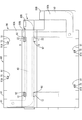
外部接続バスバー保持モジュール1は、図1に示されるように、第1プロテクタ部10、第2プロテクタ部20、中間プロテクタ部30、負極外部接続バスバー40、および正極外部接続バスバー50を備える。
負極外部接続バスバー40は、蓄電素子群60の、外部に電力を出力するための一対の出力電極端子(OUTP、OUTN)の内、負極出力端子OUTNに接続される(図4参照)。
外部接続バスバー保持モジュール1は、図1に示されるように、第1プロテクタ部10、第2プロテクタ部20、中間プロテクタ部30、負極外部接続バスバー40、および正極外部接続バスバー50を備える。
負極外部接続バスバー40は、蓄電素子群60の、外部に電力を出力するための一対の出力電極端子(OUTP、OUTN)の内、負極出力端子OUTNに接続される(図4参照)。
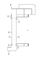
負極外部接続バスバー40は、薄板状の形状を成す(図3参照)。詳しくは、負極外部接続バスバー40は、図1に示されるように、蓄電素子群60の負極出力端子OUTNに接続される第1電極接続部40A、蓄電素子群60から電力を供給される外部機器に接続される第1外部接続部40B、および第1電極接続部40Aと第1外部接続部40Bの間に位置する中間部40Cを含む。負極外部接続バスバー40は、「第1外部接続バスバー」の一例である。ここでは、中間部40Cは、例えば、図1の矢印Wで示される範囲に相当し、第1電極接続部40Aは、中間部40Cより左側の部分に相当し、第1外部接続部40Bは、中間部40Cより右側の部分に相当する。中間部40Cは、図1に示されるように、第1電極接続部40Aから第1外部接続部40Bに延伸する形状を有している。
第1電極接続部40Aには、負極外部接続バスバー40を負極出力端子OUTNに接続するための貫通孔41が形成されている。また、第1外部接続部40Bには、負極外部接続バスバー40を外部機器に接続するための第1接続端子部42が形成されている。
正極外部接続バスバー50は、図1に示されるように、蓄電素子群60の正極出力端子OUTPに接続される第2電極接続部50A、および蓄電素子群60から電力を供給される外部機器に接続される第2外部接続部50Bを含む。第2電極接続部50Aには、正極外部接続バスバー50を正極出力端子OUTPに接続するための貫通孔51が形成されている。
また、第2外部接続部50Bには、正極外部接続バスバー50を外部機器に接続するための第2接続端子部52が形成されている。正極外部接続バスバー50は、「第2外部接続バスバー」の一例である。なお、これに限られず、逆に、「第1外部接続バスバー」が正極外部接続バスバーとされ、「第2外部接続バスバー」が負極外部接続バスバーとされてもよい。すなわち、蓄電素子群60の蓄電素子61の配置に応じて、外部接続バスバー40が正極外部接続バスバーとされ、外部接続バスバー50が負極外部接続バスバーとされてもよい。
第1プロテクタ部10は、合成樹脂等の絶縁部材から成り、図1に示されるように、バスバー保持部11、第1係止部12、延設部14、および係止片15等を含む。
バスバー保持部11は、負極外部接続バスバー40の第1電極接続部40Aを絶縁保持する。詳しくは、後述する中間プロテクタ部30の第1被保持部31を介して、負極外部接続バスバー40の中間部40Cの一部も保持する。
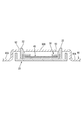
第1係止部12は、図1に示されているように、中間プロテクタ部30の幅に対応して一対設けられており、中間プロテクタ部30の第1被保持部31を介して負極外部接続バスバー40を係止する(図3参照)。なお、図3は、後述する第2プロテクタ部20に係る、第2被保持部32における断面を示すものであるが、構成が同一あるため、第1プロテクタ部10に係る、第1被保持部31における断面も示している。
延設部14は、バスバー保持部11から負極外部接続バスバー40の中間部30Cの幅方向に延設されており、その先端部に係止片15が形成されている。係止片15は、後述する蓄電素子61に形成された係止溝66(図6参照)と係合することによって、第1プロテクタ部10を、言い換えれば、外部接続バスバー保持モジュール1を蓄電素子群60に結合させる。
第2プロテクタ部20は、第1プロテクタ部10と同様に、合成樹脂等の絶縁部材から成り、図1に示されるように、第1バスバー保持部21、第2係止部22、第2バスバー保持部23、延設部24、および二個の係止片25A,25B、等を含む。第2プロテクタ部20は、図1に示されるように、第1プロテクタ部10とは所定の間隔をおいて配置されている。
第1バスバー保持部21は、負極外部接続バスバー40の第1外部接続部40Bを絶縁保持する。詳しくは、後述する中間プロテクタ部30の第2被保持部32を介して、負極外部接続バスバー40の中間部40Cの一部も保持する。
第2係止部22は、図1に示されているように、中間プロテクタ部30の幅に対応して一対設けられており、中間プロテクタ部30の第2被保持部32を介して負極外部接続バスバー40を係止する(図3参照)。なお、第1係止部12および第2係止部22の形状は、図3に示されるような断面がテーパ状の鉤型形状に限られない。
第2バスバー保持部23は、正極外部接続バスバー50を保持する。延設部24は、第1バスバー保持部21から負極外部接続バスバー40の中間部30Cの幅方向に延設されており、その両端部には係止片25A,25Bが形成されている。各係止片25A,25Bは、後述する蓄電素子61に形成された係止溝66(図6参照)と係合することによって、第2プロテクタ部20を、言い換えれば、外部接続バスバー保持モジュール1を蓄電素子群60に結合させる。
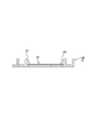
中間プロテクタ部30は、弾性変形する合成樹脂等の絶縁部材から成り、本実施形態においては、押し出し成形によって形成される。中間プロテクタ部30は、負極外部接続バスバー40の、下面40R、長手方向に延びる両側部40S、言い換えれば、幅方向(図3の矢印Yで示される方向)の両側部40S、および上面40Uの長手方向に延びる両端部40UE、言い換えれば、幅方向の両端部40UEを覆う形状を成す(図3参照)。
中間プロテクタ部30は、図1の破線で囲まれて示されるように、第1プロテクタ部10に保持される第1被保持部31(「一端部」の一例)と、第2プロテクタ部20に保持される第2被保持部32(「他端部」の一例)とを含む。図3に示されるように、第2被保持部32において、負極外部接続バスバー40の上面40Uを覆う中間プロテクタ部30の端部30Tは、第2プロテクタ部20の第2係止部22によって係止される。
具体的には、第2プロテクタ部20の底部と第2係止部22との間の空間に中間プロテクタ部30の端部30Tが挿入されることによって、中間プロテクタ部30が第2係止部22に係止される。それによって、負極外部接続バスバー40が第2プロテクタ部20に係止される。なお、このような第2被保持部32における中間プロテクタ部30と第2プロテクタ部20との係止構成は、図示されないが、第1被保持部31における中間プロテクタ部30と第1プロテクタ部10とにおいても同様の係止構成である。
中間プロテクタ部30は、第1被保持部31と第2被保持部32とにおいて、および、第1プロテクタ部10と第2プロテクタ部20との間において、負極外部接続バスバー40を保持する。すなわち、負極外部接続バスバー40は、第1被保持部31においては第1プロテクタ部10とオーバーラップして、また、第2被保持部32においては第2プロテクタ部20とオーバーラップして、それぞれ保持される。
2.蓄電モジュールの構成
本実施形態の蓄電モジュール100は、図4および図5に示すように、大きくは、複数(本実施形態では9個)の蓄電素子61を並べて構成された蓄電素子群60(図6参照)、蓄電素子群60上に取り付けられた電池接続モジュール70(図7参照)、および上記外部接続バスバー保持モジュール1によって構成される。以下に、蓄電素子群60および電池接続モジュール70について、簡単に説明する。
本実施形態の蓄電モジュール100は、図4および図5に示すように、大きくは、複数(本実施形態では9個)の蓄電素子61を並べて構成された蓄電素子群60(図6参照)、蓄電素子群60上に取り付けられた電池接続モジュール70(図7参照)、および上記外部接続バスバー保持モジュール1によって構成される。以下に、蓄電素子群60および電池接続モジュール70について、簡単に説明する。
2-1.蓄電素子群および蓄電素子
本実施形態に係る蓄電素子61は、例えば、二次電池である。図6に示すように、複数の蓄電素子61が一列に並べられて蓄電素子群60を構成している。
本実施形態に係る蓄電素子61は、例えば、二次電池である。図6に示すように、複数の蓄電素子61が一列に並べられて蓄電素子群60を構成している。
各蓄電素子61は、外形が扁平な直方体状をなしており、図6に示すように、隣接する蓄電素子61と対向する面に対して垂直な電極配置面62を有している。電極配置面62には、長手方向の両端部寄りの位置に、一対の電極端子63が配置されている。電極端子63のうち一方は正極端子63Aであり、他方は負極端子63Bである。各電極端子63は金属製であり、電極配置面62から角筒状に突出している(図5参照)。各電極端子63にはボルト82(図4参照)が結合されるネジ孔64が形成されている。
各蓄電素子61の電極配置面62において、一対の電極端子63の近傍には、上記第1プロテクタ部10の係止片15、および第2プロテクタ部20の係止片25A,25Bが係合する係止溝66が設けられている。係止溝66は、矩形の開口を有し、電極配置面62から凹状に窪んだ形態をなしている(図5および図6参照)。係止溝66は、各係止片15、25A,25Bを係止する係止部66Aを有する。各係止片15、25A,25Bが係止部66Aによって係止されることによって、外部接続バスバー保持モジュール1が、蓄電素子群60の上部に組み付けられる。
複数の蓄電素子61は、隣り合う2つの蓄電素子61において、異なる極性の電極端子63が互いに隣り合うように(つまり、1つの蓄電素子61の正極端子63Aと、これと隣接する他の蓄電素子61の負極端子63Bとが互いに隣り合うように)並べられている。そして、図6に示されるように、本実施形態では、左端の蓄電素子61の負極端子63Bが負極出力端子OUTNとされ、右端の蓄電素子61の正極端子63Aが正極出力端子OUTPとされる。
2-2.電池接続モジュール
電池接続モジュール70は、蓄電素子群60において、各蓄電素子61の電極配置面62によって構成される面に組み付けられる部材である。電池接続モジュール70は、図7に示されるように、2個の絶縁プロテクタ71、各絶縁プロテクタ71に保持され、隣り合う蓄電素子61の正極端子63Aと負極端子63Bとを接続する複数のバスバー80、バスバー80に重ねて配され電気的に接続される電圧検知端子(図示せず)、および電圧検知端子に接続される検知電線(図示せず)等を備える。また、電池接続モジュール70は、絶縁プロテクタ71の上方に上記外部接続バスバー保持モジュール1を備える。なお、これに限られず、電池接続モジュール70は、外部接続バスバー保持モジュール1を備えなくてもよい。すなわち、電池接続モジュール70と外部接続バスバー保持モジュール1とは、個別の構成とされてもよい。
電池接続モジュール70は、蓄電素子群60において、各蓄電素子61の電極配置面62によって構成される面に組み付けられる部材である。電池接続モジュール70は、図7に示されるように、2個の絶縁プロテクタ71、各絶縁プロテクタ71に保持され、隣り合う蓄電素子61の正極端子63Aと負極端子63Bとを接続する複数のバスバー80、バスバー80に重ねて配され電気的に接続される電圧検知端子(図示せず)、および電圧検知端子に接続される検知電線(図示せず)等を備える。また、電池接続モジュール70は、絶縁プロテクタ71の上方に上記外部接続バスバー保持モジュール1を備える。なお、これに限られず、電池接続モジュール70は、外部接続バスバー保持モジュール1を備えなくてもよい。すなわち、電池接続モジュール70と外部接続バスバー保持モジュール1とは、個別の構成とされてもよい。
バスバー80は金属板を打ち抜き加工することによって形成されており、図7に示すように、四隅が扁平な長方形状に切り欠かれた全体として略長方形の板状の部材である。バスバー80には、ボルト82(図4参照)を蓄電素子61のネジ孔64に結合させるための二個の接続孔81が形成されている。バスバー80の材質としては、例えば銅、銅合金、アルミニウム、アルミニウム合金、ステンレス鋼(SUS)等が挙げられる。
本実施形態では、2個の絶縁プロテクタ71が複数の蓄電素子61の並び方向に沿って並べられている。絶縁プロテクタ71は、合成樹脂等の絶縁部材によって構成されている。各絶縁プロテクタ71は、図7に示すように、上下方向に開口するとともにバスバー80を収容し保持する一対のバスバー保持部72、および外部接続バスバー保持モジュール1の各係止片15、25A,25Bを蓄電素子61の係止溝66に係合させるための開口部74等を備えている。
バスバー保持部72は、バスバー80をその内側に保持して隣り合うバスバー80と絶縁状態に保持する角筒状の収容壁73を有しており、この収容壁73は、隣接する電極端子63の保護壁としても機能する。また、絶縁プロテクタ71には、隣り合う絶縁プロテクタ71と連結するための係合部78および係合受け部79が設けられている。
3.蓄電モジュールの組立方法
上述した本実施形態の蓄電モジュール100を組み立てる際には、まず、2つの絶縁プロテクタ71を、係合部78および係合受け部79によって互いに連結する。次に、バスバー80を各絶縁プロテクタ71のバスバー保持部72内に収容する。
上述した本実施形態の蓄電モジュール100を組み立てる際には、まず、2つの絶縁プロテクタ71を、係合部78および係合受け部79によって互いに連結する。次に、バスバー80を各絶縁プロテクタ71のバスバー保持部72内に収容する。
このようにして組み立てられた電池接続モジュール70は、蓄電素子群60の電極配置面62に載置される。この状態を図8に示す。次いで、ボルト82を、バスバー80の接続孔81を介して蓄電素子61のネジ孔64と結合させる。これによって、隣り合う蓄電素子61の正極端子63Aと負極端子63Bとが接続されるとともに、電池接続モジュール70が蓄電素子群60に取付けられる。
次いで、負極外部接続バスバー40および正極外部接続バスバー50が取付けられた状態の外部接続バスバー保持モジュール1を、電池接続モジュール70の上方から蓄電素子群60に取付ける。その際、外部接続バスバー保持モジュール1の各係止片15、25A,25Bを、電池接続モジュール70の開口部74を介して、蓄電素子61の係止溝66に係合させる。
なお、負極外部接続バスバー40を外部接続バスバー保持モジュール1に取付ける前に、負極外部接続バスバー40の中間部40Cに、中間プロテクタ部30が取付けられる。すなわち、負極外部接続バスバー40が外部接続バスバー保持モジュール1に取付けられる際、中間プロテクタ部30の第1被保持部31が第1プロテクタ部10に保持され、同第2被保持部32が第2プロテクタ部20に保持される。そのため、負極外部接続バスバー40の中間部40Cが、直接、第1プロテクタ部10の第1係止部12、および第2プロテクタ部20の第2係止部22に接することはない。
また、ボルト82を、負極外部接続バスバー40の貫通孔41を介して、蓄電素子群60の負極出力端子OUTNのネジ孔64と結合させるとともに、ボルト82を、正極外部接続バスバー50の貫通孔51を介して、蓄電素子群60の正極出力端子OUTPのネジ孔64と結合させる。これによって、外部接続バスバー保持モジュール1、負極外部接続バスバー40、および正極外部接続バスバー50が、電池接続モジュール70の上から蓄電素子群60に取付けられる。このようにして、図4に示すような蓄電モジュール100が完成する。
4.実施形態1の効果
実施形態1では、外部接続バスバー保持モジュール1は、第1プロテクタ部10、第2プロテクタ部20、および中間プロテクタ部30の3個の個別のプロテクタ部から構成される。そのため、例えば、第1外部接続バスバー40の中間部40Cの長さ(形状)、および中間プロテクタ部30の長さ(形状)を、蓄電素子群60の電力取り出し位置に対応させることによって、外部接続バスバー保持モジュール1を蓄電素子群60の電力取り出しの任意の位置に対応させることができる。また、第1外部接続バスバー40の中間部40Cの長さ、および中間プロテクタ部30の長さを、蓄電素子群60の電力取り出し位置に対応させる際、第1プロテクタ部10および第2プロテクタ部20はそのままで利用でき、単に中間プロテクタ部30の長さを設計変更するだけで対応できる。
実施形態1では、外部接続バスバー保持モジュール1は、第1プロテクタ部10、第2プロテクタ部20、および中間プロテクタ部30の3個の個別のプロテクタ部から構成される。そのため、例えば、第1外部接続バスバー40の中間部40Cの長さ(形状)、および中間プロテクタ部30の長さ(形状)を、蓄電素子群60の電力取り出し位置に対応させることによって、外部接続バスバー保持モジュール1を蓄電素子群60の電力取り出しの任意の位置に対応させることができる。また、第1外部接続バスバー40の中間部40Cの長さ、および中間プロテクタ部30の長さを、蓄電素子群60の電力取り出し位置に対応させる際、第1プロテクタ部10および第2プロテクタ部20はそのままで利用でき、単に中間プロテクタ部30の長さを設計変更するだけで対応できる。
また、第1プロテクタ部10と第2プロテクタ部20とが、中間プロテクタ部30によって結合されることによって、外部接続バスバー保持モジュール1は一体化されている。そのため、外部接続バスバー保持モジュール1の蓄電素子群60への取付け作業が一回の取付け工程で簡易に行える。すなわち、本実施形態の外部接続バスバー保持モジュール1によれば、蓄電素子群60の電力取り出しの任意の位置に対応できるとともに、蓄電素子群60への取付けを簡易に行える。
また、本実施形態では、蓄電素子群60の負極出力端子(第1出力電極端子)OUTNと正極出力端子(第2出力電極端子)OUTPが、蓄電素子群60における複数の蓄電素子61の並び方向(図6の矢印X方向)の両端部に離れて配置される場合において、負極外部接続バスバー(第1外部接続バスバー)40の第1外部接続部40Bの位置、および正極外部接続バスバー(第2外部接続バスバー)50の第2外部接続部50Bの位置が、図4に示されるように、蓄電素子群60における複数の蓄電素子61の並び方向の右端側(同一の一端側)とされている。すなわち、負極出力端子OUTNと正極出力端子OUTPが蓄電素子群60の両端部に離れて配置される場合において、第1外部接続部40B(第1接続端子部42)および第2外部接続部50B(第2接続端子部52)の位置(蓄電素子群の電力取り出し位置)を、蓄電素子群60における複数の蓄電素子61の並び方向のいずれかの一端側とすることを、容易かつ的確に実現できる。
また、中間プロテクタ部30が押し出し成形によって形成されたものであるため、中間プロテクタ部30を形成する際に、中間プロテクタ部30の長さLによらず、金型が1個で済む。また、中間プロテクタ部30の長さLを蓄電素子群60の蓄電素子数に応じて、簡易に変更できる。例えば、図9に示すように中間プロテクタ部30の長さLをL2に変更することによって、図10に示すように、蓄電素子数が13個の蓄電素子群60Aに対して、容易に適用できる。
すなわち、第1プロテクタ部10、第2プロテクタ部20、および中間プロテクタ部30の3個のプロテクタのうち、中間プロテクタ部30のみの長さを押し出し成形の際に変更することによって、蓄電素子数の異なる各種の蓄電素子群60に容易に対応できる。そのため、各種の蓄電素子群60に対応させる際に、更なる金型を別途、作成する必要がなく、外部接続バスバー保持モジュール1を各種の蓄電素子群60に対応させる際の経費を、削減できる。
すなわち、第1プロテクタ部10、第2プロテクタ部20、および中間プロテクタ部30の3個のプロテクタのうち、中間プロテクタ部30のみの長さを押し出し成形の際に変更することによって、蓄電素子数の異なる各種の蓄電素子群60に容易に対応できる。そのため、各種の蓄電素子群60に対応させる際に、更なる金型を別途、作成する必要がなく、外部接続バスバー保持モジュール1を各種の蓄電素子群60に対応させる際の経費を、削減できる。
また、外部接続バスバー保持モジュール1を備えた電池接続モジュール70において、蓄電素子群60の電力取り出しの任意の位置に対応できるとともに、外部接続バスバー保持モジュール1の蓄電素子群60への取付けを簡易に行える。
<実施形態2>
次に、実施形態2を図11から図14を参照しつつ説明する。実施形態1とは、実施形態2の電池接続モジュール70Aがカバー90を有する点が異なる。そのため、以下その相違点のみを説明し、実施形態1と同一の構成には同一の部材番号を付し、その説明を省略する。
次に、実施形態2を図11から図14を参照しつつ説明する。実施形態1とは、実施形態2の電池接続モジュール70Aがカバー90を有する点が異なる。そのため、以下その相違点のみを説明し、実施形態1と同一の構成には同一の部材番号を付し、その説明を省略する。
すなわち、実施形態2の電池接続モジュール70Aは、図11に示されるように、その上部に、負極外部接続バスバー40、正極外部接続バスバー50、および蓄電素子群60を覆うカバー90を備える。
詳しくは、負極外部接続バスバー40の第1外部接続部40B、および正極外部接続バスバー50の第2外部接続部50Bは、外部との接続のためにカバー90から露出されている。また、図11に示されるように、蓄電素子群60の一部はカバー90から露出されている。すなわち、カバー90の平面形状は、図13に示されたものに限られず、要は、少なくとも、第1外部接続部40Bを除く負極外部接続バスバー40、第2外部接続部50Bを除く正極外部接続バスバー50、および各バスバー80を上方から覆う形状であればよい。
詳しくは、負極外部接続バスバー40の第1外部接続部40B、および正極外部接続バスバー50の第2外部接続部50Bは、外部との接続のためにカバー90から露出されている。また、図11に示されるように、蓄電素子群60の一部はカバー90から露出されている。すなわち、カバー90の平面形状は、図13に示されたものに限られず、要は、少なくとも、第1外部接続部40Bを除く負極外部接続バスバー40、第2外部接続部50Bを除く正極外部接続バスバー50、および各バスバー80を上方から覆う形状であればよい。
カバー90は、図12および図13に示されるように、平坦部90A、隆起部90B、および壁部90Cを含む。隆起部90Bは、図14に示されるように、外部接続バスバー保持モジュール1の中間プロテクタ部30を覆うために、平坦部90Aから所定の高さ、隆起している。
カバー90の平坦部90Aから壁部90Cへの境界部(屈曲部)には、図11および図12に示されるように、カバー90を絶縁プロテクタ71に取り付けるための4つの係止孔91が形成されている。カバー90を絶縁プロテクタ71に取り付ける際に、4つの係止孔91に絶縁プロテクタ71に形成された係止爪75を挿入させ、係止孔91の端部91Aを係止爪75に係止させることによって、カバー90は絶縁プロテクタ71に固定される。なお、係止爪75および係止孔91の個数、および形状は任意である。
また、カバー90の隆起部90Bには、図11および図12に示されるように、第1プロテクタ部10の第1係止部12、および第2プロテクタ部20の第2係止部22を貫通させる4つの貫通孔92が形成されている。なお、貫通孔92の平面形状は任意である。また、貫通孔92は、第1係止部12および第2係止部22の高さが低い場合、貫通孔92は省略されてもよいし、あるいは、第1係止部12および第2係止部22が当接しないように、対応する部分の隆起部90Bの厚さを薄くしてもよい。
なお、実施形態1における図9に示されるような中間プロテクタ部30の長さLをL2に変更する構成は、実施形態2にも適用できる。
なお、実施形態1における図9に示されるような中間プロテクタ部30の長さLをL2に変更する構成は、実施形態2にも適用できる。
5.実施形態2の効果
実施形態2では、電池接続モジュール70Aは、第1外部接続部40Bを除く負極外部接続バスバー(第1外部接続バスバー)40、第2外部接続部50Bを除く正極外部接続バスバー(第2外部接続バスバー)50、および各バスバー80を上方から覆うカバー90を備える。そのため、隣接する2つのバスバー80、あるいは、負極外部接続バスバー40と正極外部接続バスバー50とが、外部金属等によって短絡されることを防止できる。また、電池接続モジュール70A内に、塵埃等が侵入することを抑制できる。
実施形態2では、電池接続モジュール70Aは、第1外部接続部40Bを除く負極外部接続バスバー(第1外部接続バスバー)40、第2外部接続部50Bを除く正極外部接続バスバー(第2外部接続バスバー)50、および各バスバー80を上方から覆うカバー90を備える。そのため、隣接する2つのバスバー80、あるいは、負極外部接続バスバー40と正極外部接続バスバー50とが、外部金属等によって短絡されることを防止できる。また、電池接続モジュール70A内に、塵埃等が侵入することを抑制できる。
<他の実施形態>
本明細書に開示される技術は上記記述及び図面によって説明した実施形態に限定されるものではなく、例えば次のような実施形態も技術的範囲に含まれる。
本明細書に開示される技術は上記記述及び図面によって説明した実施形態に限定されるものではなく、例えば次のような実施形態も技術的範囲に含まれる。
(1)上記各実施形態では、第1外部接続バスバー40の第1外部接続部40Bの位置、および第2外部接続バスバー50の第2外部接続部50Bの位置が、図4に示されるように、蓄電素子群60における複数の蓄電素子61の並び方向の右端側(同一の一端側)とされる例を示したが、これに限られない。例えば、負極外部接続バスバー40の第1外部接続部40Bの位置が、蓄電素子群60の並び方向と直交する方向の一端側(図4の矢印Y方向の一端側)の、同並び方向の中間の位置とされてもよい。その際、第1外部接続部40Bの位置に応じて、中間プロテクタ部30と第2プロテクタ部20の平面形状、および負極外部接続バスバー40の平面形状も適宜変更される。また、第1外部接続部40Bおよび第2外部接続部50Bの位置が、複数の蓄電素子61の並び方向の右端側とされる場合であっても、図4に示される位置に限られず、例えば、右端の蓄電素子61の上端部に隣接した位置とされてもよい。
また、図4には、第1外部接続バスバー40の第1電極接続部40Aが左端の蓄電素子61の負極端子63B(OUTN:82)に接続され、第2外部接続バスバー50の第2電極接続部50Aが右端の蓄電素子61の正極端子63A(OUTP:82)に接続される例が示されるが、これに限られない。すなわち、第1電極接続部40Aおよび第2電極接続部50Aが、蓄電素子群60の両端の蓄電素子61の電極端子63(82)に接続されることに限られない。例えば、第1外部接続バスバー40の第1電極接続部40Aが、左端から三番目の蓄電素子61の負極端子63B(OUTN)に接続されるものであってもよい。
(2)上記各実施形態では、中間プロテクタ部30は、押し出し成形によって形成された弾性変形する合成樹脂で構成される例を示したが、必ずしもこれに限られない。例えば、弾性変形しない合成樹脂で構成されてもよいし、押し出し成形によって形成されたものでなくてもよい。また、中間プロテクタ部30の平面形状も、図1等に示されたもの、すなわち、蓄電素子61の配列方向(図1の矢印X方向)に伸びる直線状の形状に限られない。中間プロテクタ部30の平面形状は、負極外部接続バスバー40の中間部40Cの平面形状に対応して、適宜変更されてもよい。例えば、負極外部接続バスバー40の中間部40Cが途中で屈曲する平面形状であれば、中間プロテクタ部30の平面形状もそれに応じて途中で屈曲する平面形状であってもよい。
(3)上記各実施形態では、第2プロテクタ部20は、正極外部接続バスバー50を保持する第2バスバー保持部23を含む構成としたが、これに限られず、第2プロテクタ部20は、第2バスバー保持部23を含まなくてもよい。すなわち、第2プロテクタ部20は、正極外部接続バスバー50を保持しなくてもよい。
(4)上記各実施形態では、第1プロテクタ部10およびは第2プロテクタ部20の平面形状は図1に示したものに限られない。例えば、第1プロテクタ部10は第1係止部12を有し、第2プロテクタ部20は第2係止部22を有する構成としたが、第1係止部12および第2係止部22は省略されてもよい。
(5)上記各実施形態では、外部接続バスバー保持モジュール1は、第1プロテクタ部10、第2プロテクタ部20、および中間プロテクタ部30の3個のプロテクタから構成され、第1プロテクタ部10と第2プロテクタ部20とが、中間プロテクタ部30によって結合されることによって、外部接続バスバー保持モジュール1が一体化されている構成を示したが、外部接続バスバー保持モジュールの構成は、この構成に限られない。
要は、外部接続バスバー保持モジュールは、第1外部接続バスバーの第1電極接続部を保持する第1プロテクタ部と、第1プロテクタ部と間隔を隔てて配置され、第1外部接続バスバーの第1外部接続部を保持する第2プロテクタ部と、第1プロテクタ部と第2プロテクタ部との間に位置し、第1プロテクタと第2プロテクタ部との間において第1外部接続バスバーの中間部を保持する中間プロテクタ部と、を備える、構成であればよい。
要は、外部接続バスバー保持モジュールは、第1外部接続バスバーの第1電極接続部を保持する第1プロテクタ部と、第1プロテクタ部と間隔を隔てて配置され、第1外部接続バスバーの第1外部接続部を保持する第2プロテクタ部と、第1プロテクタ部と第2プロテクタ部との間に位置し、第1プロテクタと第2プロテクタ部との間において第1外部接続バスバーの中間部を保持する中間プロテクタ部と、を備える、構成であればよい。
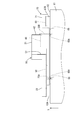
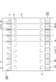
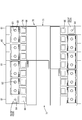
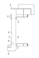
例えば、図15-図17の外部接続バスバー保持モジュール1Aに示されるように、中間プロテクタ部30Aは、第2プロテクタ部20Aと一体に形成されており、中間プロテクタ部30Aの一端部26Bが、一体化されていない第1プロテクタ部10Aによって保持されている構成であってもよい。その際、例えば、図17に示されるように、第1プロテクタ部10Aにおいて、中間プロテクタ部の一端部26Bに対応する位置に、一端部26を保持する保持凹部16を形成するようにしてもよい。また、図17および図18に示されるように、第1プロテクタ部10Aには中間プロテクタ部30Aの側壁26Aの上部に係合し、一端部26Bを係止する一対の係止部12A、第2プロテクタ部20Aには第1外部接続バスバー40を係止する一対の係止部22Aを設けるようにしてもよい。
なお、この構成とは逆に、中間プロテクタ部30Aは、第1プロテクタ部10Aと一体に形成されており、中間プロテクタ部30Aの一端部が、一体化されていない第2プロテクタ部20Aによって保持されている構成であってもよい。
これらの場合、中間プロテクタ部30Aは、第1プロテクタ部10Aまたは第2プロテクタ部20Aと一体化されている。そのため、第1外部接続バスバー40を保持するための構成を簡易化できる、すなわち、中間プロテクタ部30Aを保持する構成を、第1プロテクタ部10Aまたは第2プロテクタ部20Aにおいて省略できる。それに伴って、外部接続バスバー保持モジュール1Aとしてのとしての構成を簡略化できる。
これらの場合、中間プロテクタ部30Aは、第1プロテクタ部10Aまたは第2プロテクタ部20Aと一体化されている。そのため、第1外部接続バスバー40を保持するための構成を簡易化できる、すなわち、中間プロテクタ部30Aを保持する構成を、第1プロテクタ部10Aまたは第2プロテクタ部20Aにおいて省略できる。それに伴って、外部接続バスバー保持モジュール1Aとしてのとしての構成を簡略化できる。
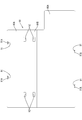
また、図18-図20の外部接続バスバー保持モジュール1Bに示されるように、中間プロテクタ部30Bは、第1プロテクタ部10Bおよび第2プロテクタ部20Bと一体に形成されている構成であってもよい。すなわち、図1に示される平面形状の第1プロテクタ部10、第2プロテクタ部20、および中間プロテクタ部30が一体化された、1個の合成樹脂製のプロテクタ5によって構成されてもよい。その際、例えば、図19および図20に示されるように、第1プロテクタ部10Bには、第1外部接続バスバー40を係止する一対の係止部12Bを設けるようにしてもよい。
この場合、中間プロテクタ部30Bは、第1プロテクタ部10Bおよび第2プロテクタ部20Bと一体化されている。そのため、第1外部接続バスバー40を保持するための構成をさらに簡易化できる、すなわち、中間プロテクタ部30Bを保持する構成を省略できる。それに伴って、外部接続バスバー保持モジュール1Bとしての構成をさらに簡略化できる。
また、上記中間プロテクタ部30Aの一部を他のプロテクタ部と一体化する場合、あるいは中間プロテクタ部30Bの全体を他のプロテクタ部と一体化する場合であっても、中間プロテクタ部に相当する部分の長さ(形状)を変更することによって、蓄電素子群60の電力取り出しの任意の位置に対応できるとともに、外部接続バスバー保持モジュールの蓄電素子群60への取付けを簡易に行える。
また、上記中間プロテクタ部30Aの一部を他のプロテクタ部と一体化する場合、あるいは中間プロテクタ部30Bの全体を他のプロテクタ部と一体化する場合であっても、中間プロテクタ部に相当する部分の長さ(形状)を変更することによって、蓄電素子群60の電力取り出しの任意の位置に対応できるとともに、外部接続バスバー保持モジュールの蓄電素子群60への取付けを簡易に行える。
1、1A、1B…外部接続バスバー保持モジュール
10、10A、10B…第1プロテクタ部
20、20A、20B…第2プロテクタ部
30、30A、30B…中間プロテクタ部
31…第1被保持部(一端部)
32…第2被保持部(他端部)
40…負極外部接続バスバー(第1外部接続バスバー)
40A…第1電極接続部
40B…第1外部接続部
50…正極外部接続バスバー(第2外部接続バスバー)
50A…第2電極接続部
50B…第2外部接続部
60…蓄電素子群
61…蓄電素子
70、70A…電池接続モジュール
71…絶縁プロテクタ
80…バスバー
90…カバー
OUTN…負極出力端子(第1出力電極端子)
OUTP…正極出力端子(第2出力電極端子)
10、10A、10B…第1プロテクタ部
20、20A、20B…第2プロテクタ部
30、30A、30B…中間プロテクタ部
31…第1被保持部(一端部)
32…第2被保持部(他端部)
40…負極外部接続バスバー(第1外部接続バスバー)
40A…第1電極接続部
40B…第1外部接続部
50…正極外部接続バスバー(第2外部接続バスバー)
50A…第2電極接続部
50B…第2外部接続部
60…蓄電素子群
61…蓄電素子
70、70A…電池接続モジュール
71…絶縁プロテクタ
80…バスバー
90…カバー
OUTN…負極出力端子(第1出力電極端子)
OUTP…正極出力端子(第2出力電極端子)
Claims (8)
- 正極及び負極の電極端子を有する複数の蓄電素子から成る蓄電素子群に取り付けられる外部接続バスバー保持モジュールであって、
前記蓄電素子群は、一方の極性の電力を出力する第1出力電極端子と、他方の極性の電力を出力する第2出力電極端子とを含み、
当該モジュールは、
前記第1出力電極端子に接続される第1電極接続部と、外部機器に接続される第1外部接続部と、前記第1電極接続部と第1外部接続部との間に位置する中間部と含む第1外部接続バスバーと、
前記第2出力電極端子に接続される第2電極接続部と、前記外部機器に接続される第2外部接続部とを含む第2外部接続バスバーと、
前記第1外部接続バスバーの前記第1電極接続部を保持する第1プロテクタ部と、
前記第1プロテクタ部と間隔を隔てて配置され、前記第1外部接続バスバーの前記第1外部接続部を保持する第2プロテクタ部と、
前記第1プロテクタ部と前記第2プロテクタ部との間に位置し、前記第1プロテクタ部と前記第2プロテクタ部との間において前記第1外部接続バスバーの前記中間部を保持する中間プロテクタ部と、を備える、外部接続バスバー保持モジュール。 - 請求項1に記載の外部接続バスバー保持モジュールにおいて、
前記中間プロテクタ部は、前記第1プロテクタ部および前記第2プロテクタ部とは個別に形成されており、
前記中間プロテクタ部の一端部が前記第1プロテクタ部によって保持され、他端部が前記第2プロテクタ部によって保持されている、外部接続バスバー保持モジュール。 - 請求項2に記載の外部接続バスバー保持モジュールにおいて、
前記中間プロテクタ部は、押し出し成形された合成樹脂によって構成されている、外部接続バスバー保持モジュール。 - 請求項1に記載の外部接続バスバー保持モジュールにおいて、
前記中間プロテクタ部は、前記第1プロテクタ部または前記第2プロテクタ部と一体に形成されており、
前記中間プロテクタ部の一端部が、一体化されていない前記第1プロテクタ部または前記第2プロテクタ部によって保持されている、外部接続バスバー保持モジュール。 - 請求項1に記載の外部接続バスバー保持モジュールにおいて、
前記中間プロテクタ部は、前記第1プロテクタ部および前記第2プロテクタ部と一体に形成されている、外部接続バスバー保持モジュール。 - 請求項1から請求項5の何れか一項に記載の外部接続バスバー保持モジュールにおいて、
前記第1出力電極端子は、前記蓄電素子群における前記複数の蓄電素子の並び方向の一端に位置する蓄電素子の一方の極性の電極端子によって構成されており、
第2出力電極端子は、前記蓄電素子群における前記複数の蓄電素子の並び方向の他端に位置する蓄電素子の他方の極性の電極端子によって構成されおり、
前記第1外部接続バスバーの前記中間部は、前記第1電極接続部から前記第1外部接続部に延伸する形状を有し、
前記第2プロテクタ部は、前記第2外部接続バスバーを保持する、外部接続バスバー保持モジュール。 - 前記蓄電素子群の上部に取り付けられる電池接続モジュールであって、
請求項1から請求項6のいずれか一項に記載の外部接続バスバー保持モジュールと、
隣り合う前記蓄電素子の前記正極の電極端子と前記負極の電極端子とを接続する複数のバスバーと、
前記複数のバスバーを保持する絶縁プロテクタと、を備え、
前記外部接続バスバー保持モジュールは、前記絶縁プロテクタの上方に配置されている、電池接続モジュール。 - 請求項7に記載の電池接続モジュールにおいて、さらに、
少なくとも、前記第1外部接続部を除く前記第1外部接続バスバー、前記第2外部接続部を除く前記第2外部接続バスバー、および前記複数のバスバーを覆うカバーを備える、電池接続モジュール。
Priority Applications (2)
| Application Number | Priority Date | Filing Date | Title |
|---|---|---|---|
| CN201780017267.3A CN108780871B (zh) | 2016-03-25 | 2017-03-14 | 外部连接总线保持模块及电池连接模块 |
| US16/077,643 US10720627B2 (en) | 2016-03-25 | 2017-03-14 | External connection bus bar holding module and battery connection module |
Applications Claiming Priority (6)
| Application Number | Priority Date | Filing Date | Title |
|---|---|---|---|
| JP2016061585 | 2016-03-25 | ||
| JP2016-061585 | 2016-03-25 | ||
| JP2016173325 | 2016-09-06 | ||
| JP2016-173325 | 2016-09-06 | ||
| JP2016-243194 | 2016-12-15 | ||
| JP2016243194A JP6332428B2 (ja) | 2016-03-25 | 2016-12-15 | 外部接続バスバー保持モジュールおよび電池接続モジュール |
Publications (1)
| Publication Number | Publication Date |
|---|---|
| WO2017163995A1 true WO2017163995A1 (ja) | 2017-09-28 |
Family
ID=59899520
Family Applications (1)
| Application Number | Title | Priority Date | Filing Date |
|---|---|---|---|
| PCT/JP2017/010088 Ceased WO2017163995A1 (ja) | 2016-03-25 | 2017-03-14 | 外部接続バスバー保持モジュールおよび電池接続モジュール |
Country Status (1)
| Country | Link |
|---|---|
| WO (1) | WO2017163995A1 (ja) |
Cited By (3)
| Publication number | Priority date | Publication date | Assignee | Title |
|---|---|---|---|---|
| CN110518182A (zh) * | 2018-05-21 | 2019-11-29 | 株式会社自动网络技术研究所 | 连接模块 |
| JP2021044095A (ja) * | 2019-09-09 | 2021-03-18 | トヨタ自動車株式会社 | 拘束部材 |
| KR20220095217A (ko) * | 2019-12-03 | 2022-07-06 | 컨템포러리 엠퍼렉스 테크놀로지 씨오., 리미티드 | 전지 모듈군, 전지 팩, 장치 및 전지 모듈군의 제조방법 |
Citations (5)
| Publication number | Priority date | Publication date | Assignee | Title |
|---|---|---|---|---|
| JP2004095381A (ja) * | 2002-08-30 | 2004-03-25 | Yazaki Corp | バッテリ接続プレートおよびその取付構造 |
| JP2004362997A (ja) * | 2003-06-05 | 2004-12-24 | Yazaki Corp | バッテリ接続プレート |
| JP2006222043A (ja) * | 2005-02-14 | 2006-08-24 | Yazaki Corp | バッテリ接続プレート |
| JP2013016381A (ja) * | 2011-07-05 | 2013-01-24 | Auto Network Gijutsu Kenkyusho:Kk | 電池配線モジュール |
| JP2014007105A (ja) * | 2012-06-26 | 2014-01-16 | Auto Network Gijutsu Kenkyusho:Kk | 配線モジュール |
-
2017
- 2017-03-14 WO PCT/JP2017/010088 patent/WO2017163995A1/ja not_active Ceased
Patent Citations (5)
| Publication number | Priority date | Publication date | Assignee | Title |
|---|---|---|---|---|
| JP2004095381A (ja) * | 2002-08-30 | 2004-03-25 | Yazaki Corp | バッテリ接続プレートおよびその取付構造 |
| JP2004362997A (ja) * | 2003-06-05 | 2004-12-24 | Yazaki Corp | バッテリ接続プレート |
| JP2006222043A (ja) * | 2005-02-14 | 2006-08-24 | Yazaki Corp | バッテリ接続プレート |
| JP2013016381A (ja) * | 2011-07-05 | 2013-01-24 | Auto Network Gijutsu Kenkyusho:Kk | 電池配線モジュール |
| JP2014007105A (ja) * | 2012-06-26 | 2014-01-16 | Auto Network Gijutsu Kenkyusho:Kk | 配線モジュール |
Cited By (7)
| Publication number | Priority date | Publication date | Assignee | Title |
|---|---|---|---|---|
| CN110518182A (zh) * | 2018-05-21 | 2019-11-29 | 株式会社自动网络技术研究所 | 连接模块 |
| JP2021044095A (ja) * | 2019-09-09 | 2021-03-18 | トヨタ自動車株式会社 | 拘束部材 |
| JP7131514B2 (ja) | 2019-09-09 | 2022-09-06 | トヨタ自動車株式会社 | 拘束部材 |
| KR20220095217A (ko) * | 2019-12-03 | 2022-07-06 | 컨템포러리 엠퍼렉스 테크놀로지 씨오., 리미티드 | 전지 모듈군, 전지 팩, 장치 및 전지 모듈군의 제조방법 |
| JP2023504481A (ja) * | 2019-12-03 | 2023-02-03 | 寧徳時代新能源科技股▲分▼有限公司 | 電池モジュール、電池パック、装置及び電池モジュールの製造方法 |
| JP7395744B2 (ja) | 2019-12-03 | 2023-12-11 | 寧徳時代新能源科技股▲分▼有限公司 | 電池モジュール、電池パック、装置及び電池モジュールの製造方法 |
| KR102834818B1 (ko) | 2019-12-03 | 2025-07-17 | 컨템포러리 엠퍼렉스 테크놀로지 (홍콩) 리미티드 | 전지 모듈군, 전지 팩, 장치 및 전지 모듈군의 제조방법 |
Similar Documents
| Publication | Publication Date | Title |
|---|---|---|
| JP6332428B2 (ja) | 外部接続バスバー保持モジュールおよび電池接続モジュール | |
| JP6299898B1 (ja) | 接続モジュール | |
| JP6512147B2 (ja) | 外部接続バスバー保持構造 | |
| US9780351B2 (en) | Wiring module | |
| WO2014014000A1 (ja) | バスバモジュール | |
| JP6299917B1 (ja) | 接続モジュール | |
| US10131296B2 (en) | Insert bus bar plate and method for manufacturing the same | |
| JP6202338B2 (ja) | 配線モジュール、配線モジュール中間体、及び配線モジュールの製造方法 | |
| JP6344362B2 (ja) | 蓄電モジュールおよび電池接続モジュール | |
| JP6286141B2 (ja) | バスバモジュール及び電源装置 | |
| WO2017195546A1 (ja) | 接続モジュール | |
| US10410769B2 (en) | Connection module | |
| WO2017163995A1 (ja) | 外部接続バスバー保持モジュールおよび電池接続モジュール | |
| US10608230B2 (en) | External connection busbar holding module and connection module | |
| JP6440004B1 (ja) | 接続モジュール | |
| JP2019192558A (ja) | 接続モジュールおよび蓄電モジュール | |
| JP2013041738A (ja) | ヒューズユニット |
Legal Events
| Date | Code | Title | Description |
|---|---|---|---|
| 121 | Ep: the epo has been informed by wipo that ep was designated in this application |
Ref document number: 17770038 Country of ref document: EP Kind code of ref document: A1 |
|
| 122 | Ep: pct application non-entry in european phase |
Ref document number: 17770038 Country of ref document: EP Kind code of ref document: A1 |