WO2017163979A1 - リニアモータ、ステージ装置 - Google Patents
リニアモータ、ステージ装置 Download PDFInfo
- Publication number
- WO2017163979A1 WO2017163979A1 PCT/JP2017/009970 JP2017009970W WO2017163979A1 WO 2017163979 A1 WO2017163979 A1 WO 2017163979A1 JP 2017009970 W JP2017009970 W JP 2017009970W WO 2017163979 A1 WO2017163979 A1 WO 2017163979A1
- Authority
- WO
- WIPO (PCT)
- Prior art keywords
- field magnet
- yoke
- magnet
- support member
- linear motor
- Prior art date
- Legal status (The legal status is an assumption and is not a legal conclusion. Google has not performed a legal analysis and makes no representation as to the accuracy of the status listed.)
- Ceased
Links
Images





Classifications
-
- H—ELECTRICITY
- H02—GENERATION; CONVERSION OR DISTRIBUTION OF ELECTRIC POWER
- H02K—DYNAMO-ELECTRIC MACHINES
- H02K41/00—Propulsion systems in which a rigid body is moved along a path due to dynamo-electric interaction between the body and a magnetic field travelling along the path
- H02K41/02—Linear motors; Sectional motors
- H02K41/03—Synchronous motors; Motors moving step by step; Reluctance motors
Definitions
- the present invention relates to a linear motor.
- Patent Document 1 describes a linear motor including a stator and a mover that are arranged to face each other via a magnetic gap.
- the stator includes a flat field yoke, and a plurality of main pole magnets and auxiliary pole magnets fixed to the field yoke so as to alternately have different polarities. And a reinforcing member provided on the surface on the magnetic gap side of the auxiliary pole magnet and the surface on the side of two adjacent main pole magnets.
- the linear motor described in Patent Document 1 includes a main pole magnet and an auxiliary pole magnet having a Halbach array structure.
- the reinforcing member mainly two shapes are disclosed. One of them covers the surface on the magnetic gap side of the auxiliary pole magnet and the surface on the side of two adjacent main pole magnets, and exposes the surface on the field yoke side. The other is arranged so as to sandwich the auxiliary pole magnet from both sides of the moving direction of the mover to expose the surface of the auxiliary pole magnet on the magnetic gap side.
- the reinforcing member is fixed to the auxiliary pole magnet with an adhesive on the field yoke side surface or the magnetic gap side surface of the auxiliary pole magnet and on both sides in the movable direction of the auxiliary pole magnet. Therefore, even if this reinforcing member produces the action of preventing the breakage of the auxiliary pole magnet, it cannot be said that the action on the main pole magnet is sufficient.
- the field magnet which is the main pole magnet
- the field magnet may have variations in the bonding strength between the field magnet and the yoke due to dimensional variation and non-flatness of the field magnet. For this reason, there is a problem that it is difficult to completely prevent a part of the field magnet from being detached from the yoke during or after the assembly process.
- One of the objects of the present invention is to provide a linear motor capable of stably holding a field magnet by suppressing variations in the fixing strength of the field magnet.
- a linear motor includes a stator including a yoke, a field magnet, and a support member.
- Each field magnet has a front surface and a back surface on which magnetic pole surfaces are formed, the back surface is fixed to the yoke, and the supporting member is movable from the first portion and the first portion bonded to the side surface of the field magnet.
- a second portion extending in a direction away from the field magnet in the movable direction of the child and bonded to the yoke.
- the field magnet is bonded to the first portion of the reinforcing member where the second portion is bonded to the yoke, variations in the fixing strength of the field magnet can be suppressed.
- a stage apparatus includes the linear motor described above.
- a linear motor capable of stably holding a field magnet can be provided.
- FIG. 1 is a perspective view of a linear motor 2 according to an embodiment.
- the linear motor 2 includes a stator 20 and a mover 10.
- the stator 20 mainly includes a yoke 22, a field magnet 24, a support member 12, and an auxiliary pole magnet 26 that is a magnet different from the field magnet 24, and a magnetic field 34 is provided in the magnetic gap 34.
- the mover 10 is provided such that the magnetic gap 34 of the stator 20 is movable in the movable direction.
- the support member 12 is not shown.
- description will be made based on the XYZ orthogonal coordinate system.
- the X-axis direction corresponds to the horizontal left-right direction
- the Y-axis direction corresponds to the horizontal front-back direction
- the Z-axis direction corresponds to the vertical up-down direction.
- the Y-axis direction and the Z-axis direction are each orthogonal to the X-axis direction.
- the X-axis direction may be referred to as the left direction or the right direction
- the Y-axis direction may be referred to as the forward direction or the rear direction
- the Z-axis direction may be referred to as the upward direction or the downward direction.
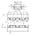
- FIG. 2 is a plan view of the stator 20 according to the embodiment.
- the yoke 22 supports the field magnet 24 and the auxiliary pole magnet 26 and constitutes a magnetic circuit as a back yoke for the field magnet 24 and the auxiliary pole magnet 26.
- the yoke 22 may be formed in a substantially rectangular shape that is long in the X-axis direction, for example.
- the field magnet 24 forms a field magnetic field in the magnetic gap 34.
- the auxiliary pole magnet 26 forms a Halbach array structure together with the field magnet 24 to reinforce the field magnetic field of the magnetic gap 34.
- a plurality of field magnets 24 are bonded and fixed inside the yoke 22 (on the magnetic gap 34 side) in a plurality of straight lines in the moving direction (X-axis direction) of the mover 10.
- the auxiliary pole magnet 26 is fixed between two adjacent field magnets 24.
- the field magnet 24 and the auxiliary pole magnet 26 are formed of, for example, a magnetic material containing a rare earth element by a sintering method.
- the field magnet 24 and the auxiliary pole magnet 26 may have a surface layer such as a plating layer.
- the field magnet 24 and the auxiliary pole magnet 26 are formed in a rectangular plate shape, for example.
- the field magnet 24 has a thin rectangular parallelepiped shape in the Y-axis direction, has a front surface 24 f and a back surface 24 b on which magnetic pole surfaces are formed, and the back surface 24 b is fixed to the inner side surface 22 a of the yoke 22. That is, the magnetization direction 24m of the field magnet 24 is formed in a direction from the front surface 24f toward the back surface 24b along the Y axis.
- the field magnet 24 has a left side surface 24h extending from the left end of the front surface 24f toward the back surface 24b, and a right side surface 24r extending from the right end of the front surface 24f toward the back surface 24b.
- the auxiliary pole magnet 26 has a thin rectangular parallelepiped shape in the Y-axis direction, has a front surface and a back surface parallel to the X axis, and the back surface is fixed to the inner side surface 22 a of the yoke 22. Magnetic pole surfaces are formed on both side surfaces of the auxiliary magnet 26, respectively. That is, the magnetization direction 26m of the auxiliary pole magnet 26 is formed parallel to the X axis.
- the magnetic circuit of the linear motor has a configuration in which the magnetic field of the auxiliary pole magnet 26 can be concentrated on the magnetic gap 34 side in order to improve the motor characteristics while suppressing the saturation of the yoke 22. Therefore, the magnetization direction 26m of the supplementary magnet 26 according to the embodiment is formed in a direction different from the magnetization direction 24m of the field magnet 24 by 90 °. With this configuration, the field magnet 24 and the auxiliary magnet 26 form a Halbach array structure, and the magnetic field of the field magnet 24 can be collected on the magnetic gap 34 side.
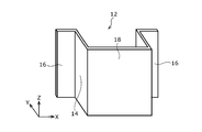
- FIG. 3 is a perspective view of the support member 12.
- the support member 12 is provided in order to prevent a part of the field magnet 24 from being separated from the yoke 22.
- the support member 12 includes a first portion 14 and a second portion 16.
- the first portion 14 may be bonded to the side surfaces 24r and 24h of the field magnet 24 with an adhesive as necessary, or may be non-bonded.
- the second portion 16 extends from the first portion 14 in a movable direction (X-axis direction) away from the field magnet 24 and is bonded to the yoke 22. With this configuration, the side surfaces 24 r and 24 h of the field magnet 24 are supported by the yoke 22 via the support member 12.
- the support member 12 of the embodiment includes the third portion 18, and the third portion 18 has a shape that covers the front surface 24 f of the field magnet 24.
- the third portion 18 may be provided so as to cover the front surface 24f.
- the third portion 18 supports the field magnet 24 from the Y-axis direction toward the yoke 22. Since the field magnet 24 is pressed by the third portion 18 from the Y-axis direction, the separation of the field magnet 24 from the yoke 22 can be effectively suppressed. As shown in FIG.
- the support member 12 is formed by bending a pair of first portions 14, a pair of second portions 16, and a third portion 18 together into a ⁇ shape.
- a pair of first portion 14 and third portion 18 form a U-shaped recess, and the field magnet 24 is accommodated in the recess.
- a bent portion 12 e is formed between the first portion 14 and the third portion 18, and the bent portion 12 e has a shape corresponding to the corner portion 24 fa on the front 24 f side of the field magnet 24. .
- the bent portion 12e is bent substantially at a right angle, and the corner C or corner R dimension of the corner inside the bent portion 12e is formed smaller than the corner C or corner R size of the corner portion 24fa. With this configuration, the gap between the support member 12 and the field magnet 24 can be reduced.
- the gap between the third portion 18 of the support member 12 and the front surface 24f of the field magnet 24 is as small as possible. Therefore, in the support member 12 of the embodiment, the third portion 18 is bonded to the front surface 24 f of the field magnet 24. Since the third portion 18 is bonded to the front surface 24f, the separation of the field magnet 24 can be more effectively suppressed. It is not essential that the third portion 18 is bonded to the field magnet 24.
- the third portion 18 of the support member 12 extends from the first portion 14 in the direction opposite to the extending direction of the second portion 16.
- the second portion 16 bends substantially perpendicular to the first portion 14 and the third portion 18 bends substantially perpendicular to the first portion 14.
- the third portion 18 covering the front surface 24f of the field magnet 24 has magnetism, it is conceivable that the magnetic flux is short-circuited through the support member 12 and the magnetic flux that can be effectively used is reduced. Therefore, the third portion 18 of the support member 12 according to the embodiment is formed of a nonmagnetic stainless steel plate or an aluminum alloy. Further, if the third portion 18 covering the front surface 24f is thick, it is conceivable that the magnetic flux that effectively acts on the mover 10 is reduced by making the field magnet 24 thinner in the Y-axis direction accordingly. Therefore, the thickness of the third portion 18 of the support member 12 of the embodiment is formed to be 1 mm or less.
- the third portion 18 covering the front surface 24 f of the field magnet 24 may be formed thinner than the first portion 14. As the third portion 18 is formed thinner, the field magnet 24 can be made thicker in the Y-axis direction to increase the effective magnetic flux. Such a configuration can be realized by adjusting the pressing process.
- the stator 20 includes an auxiliary pole magnet 26 fixed to one surface of the yoke 22. At least a part of the second portion 16 is sandwiched between the auxiliary pole magnet 26 and the yoke 22. Since the second portion 16 is pressed against the yoke 22 by the attractive force between the auxiliary pole magnet 26 and the yoke 22, peeling from the yoke 22 is suppressed.
- the support member 12 includes a first portion 14 bonded to the side surfaces 24r and 24h of the field magnet 24, and a direction away from the field magnet 24 in a movable direction from the first portion 14. And the second portion 16 extending and bonded to the yoke 22, the side surfaces 24 r and 24 h of the field magnet 24 are supported by the support member 12.
- the support member 12 since the support member 12 includes the third portion 18 that covers the front surface 24f of the field magnet 24, the front surface 24f of the field magnet 24 is supported by the support member 12. For this reason, the position of the field magnet 24 becomes difficult to shift by pressing the field magnet 24 from the front 24f side. Further, since the third portion 18 covers at least a part of the field magnet 24, gas generation from the field magnet 24 can be suppressed even when the third portion 18 is used in a reduced-pressure vacuum environment. Further, when the field magnet 24, the supplementary pole magnet 26, and the support member 12 are assembled in advance, the alignment with the field magnet 24 is facilitated by attaching the supplementary magnet 26 to the support member 12. .
- the third portion 18 can be bonded to the front surface 24f.
- the third portion 18 is formed from a nonmagnetic stainless steel plate having a thickness of 1 mm or less, the decrease in magnetic flux acting on the mover 10 can be mitigated.
- the bent portion 12e having a shape corresponding to the shape on the front surface 24f side of the field magnet 24 is provided between the third portion 18 and the first portion 14, the third portion 18 is provided. Can be brought into close contact with the front surface 24f of the field magnet 24.
- the auxiliary pole magnet 26 is further provided, and the second portion 16 includes a portion sandwiched between the yoke 22 and the auxiliary pole magnet 26. It is fixed between the yokes 22.
- the support member 12 bonded to the field magnet 24 is sandwiched between the yokes 22 of the auxiliary pole magnet 26, a force in the direction of the yoke 22 is applied, and the support member 12 is not easily displaced.
- FIG. 4 is a plan view of the stator 20 of the first modification
- FIG. 5 is a perspective view of the support member 12 of the stator 20.
- This modification differs from the embodiment in the shape of the support member 12, and the other configurations are the same.
- the third portion 18 covering the front surface of the field magnet 24 is separated into two parts in the middle of the X-axis direction, and is composed of two bodies. That is, the support member 12 includes a support member 12a provided on one side of the field magnet 24 and a support member 12b provided on the other side.
- the support members 12a and 12b can be brought into close contact with the field magnet 24 from the X-axis direction. Also in this modification, the same effect can be obtained in the configuration common to the embodiment.
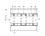
- FIG. 6 is a plan view of the stator 20 of the second modification
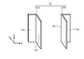
- FIG. 7 is a perspective view of the support member 12 of the stator 20.
- This modification differs from the embodiment in the shape of the support member 12, and the other configurations are the same.
- the third portion 18 that covers the front surface of the field magnet 24 is not provided, and the front surface of the field magnet 24 is exposed.
- the support member 12 of this modification includes a support member 12a provided on one side of one field magnet 24 and a support member 12b provided on the other side.
- FIG. 8 is a plan view of the stator 20 of the third modification.
- This modified example is different from the embodiment in that the supplementary pole magnet 26 is not provided, and the other configurations are the same. Since the auxiliary pole magnet 26 is not provided, the manufacturing labor is reduced. Also in this modification, the same effect can be obtained in the configuration common to the embodiment.
- the support member 12 demonstrated the example formed from metal materials, such as stainless steel, it is not limited to this.
- a part or all of the support member may be formed of a non-metallic material such as a resin reinforced with carbon fibers.
- the support member 12 has been described with respect to the example in which the dimension in the Z-axis direction is substantially equal to the dimension in the Z-axis direction of the field magnet 24, the present invention is not limited to this.
- the Z-axis direction dimension of the support member 12 may be formed smaller than or larger than the Z-axis direction dimension of the field magnet 24.
- FIG. 9 is a plan view of the stage apparatus 100 using the linear motor 2 according to the embodiment.
- This stage apparatus 100 is called an XY stage, and positions an object in the X direction and the Y direction.
- the stage apparatus 100 mainly includes a Y stage 120, an X stage 130, and a surface plate 140.
- the Y stage 120 includes a pair of sliders 124 and a horizontal member 122 that extends horizontally between the pair of sliders 124.
- An X linear motor 2X that moves the X stage 130 in the X direction is provided on the horizontal member 122.
- the X linear motor 2 ⁇ / b> X includes a stator 20 that is fixed to the horizontal member 122 and extends in the X direction, and a mover (coil) 10 that is coupled to the lower surface of the X stage 130.
- the mover 10 of the X linear motor 2X the X stage 130 is positioned in the X direction.
- a pair of Y linear motors 2Y are provided at both ends of the surface plate 140.
- Each of the Y linear motors 2Y includes a mover 10 and a stator 20.
- the slider 124 is fixed to the stator 20 of the Y linear motor 2Y.
- the Y stage 120 is positioned in the Y direction by controlling the mover 10 of the Y linear motor 2Y.
- the above is the configuration of the stage apparatus 100.
- the linear motor 2 according to the embodiment can be suitably used for the X linear motor 2X or the Y linear motor 2Y of the stage apparatus 100.
- the stage apparatus 100 can be used for positioning a wafer or a glass substrate in an exposure apparatus, or can be used for an actuator used in a scanning electron microscope (SEM).
- SEM scanning electron microscope
- the present invention can be used for a linear motor.
Landscapes
- Engineering & Computer Science (AREA)
- Physics & Mathematics (AREA)
- Chemical & Material Sciences (AREA)
- Combustion & Propulsion (AREA)
- Electromagnetism (AREA)
- Power Engineering (AREA)
- Linear Motors (AREA)
Abstract
リニアモータにおいて、固定子20は、ヨーク22と、界磁磁石24と、支持部材12と、を含む。界磁磁石24は、それぞれ磁極面が形成される正面24fと背面24bとを有し、背面24bがヨーク22に固定される。支持部材12は、界磁磁石24の側面に接着される第1部分14と、第1部分14から可動子の可動方向にて界磁磁石24から遠ざかる方向に延在してヨーク22に接着される第2部分16と、を含む。
Description
本発明は、リニアモータに関する。
電気エネルギーを直線運動に変換するためにリニアモータが利用される。例えば、特許文献1には、磁気的空隙を介して対向配置される固定子と可動子を備えるリニアモータが記載されている。
特許文献1に記載のリニアモータでは、固定子は、平板状の界磁ヨークと、界磁ヨークに交互に極性が異なるように直線状に並べて固定された複数の主極磁石及び補極磁石と、補極磁石の磁気的空隙側の面及び2つの隣接する主極磁石側の面に設けられた補強部材とを有する。
ところで、特許文献1に記載のリニアモータでは、ハルバッハ配列構造である主極磁石と補極磁石とを備えている。補強部材としては主に2つの形状が開示されている。その一方は、補極磁石の磁気的空隙側の面及び2つの隣接する主極磁石側の面を覆い、界磁ヨーク側の面を露出させる。その他方は、補極磁石を可動子の可動方向両側より挟むように配置されて補極磁石の磁気的空隙側の面を露出させる。いずれの形状においても、補強部材は、補極磁石の界磁ヨーク側の面または磁気的空隙側の面と、補極磁石の可動方向両側で、補極磁石に接着剤により固定されている。したがって、この補強部材は補極磁石の破損防止の作用を生じるとしても主極磁石への作用が十分であるとはいえない。
一方で、このようなリニアモータでは、主極磁石である界磁磁石の寸法バラツキ、非平坦性に起因して、界磁磁石のヨークとの接着強度にばらつきが生じることがある。このため、組み立て工程中、あるいは組み立て工程後において、界磁磁石の一部がヨークから剥離することを完全に防ぐことは難しい問題がある。
また、界磁磁石のヨークとの固定強度を高めるために、界磁磁石やヨークの接着面に接着溝を設け強力な接着剤を多量に塗布することも考えられる。しかし、この場合、接着溝の部分で磁気抵抗が増えて磁気的な性能が低下し、接着溝の加工に余計な手間がかかる問題がある。また、強力な接着剤は使用上での管理が難しく接着強度が安定しない懸念もある。
つまり、従来のリニアモータでは、界磁磁石の固定強度の変動を抑制して界磁磁石を安定して保持可能とする観点から改善する余地があった。
つまり、従来のリニアモータでは、界磁磁石の固定強度の変動を抑制して界磁磁石を安定して保持可能とする観点から改善する余地があった。
本発明の目的のひとつは、界磁磁石の固定強度のばらつきを抑制して界磁磁石を安定して保持可能なリニアモータを提供することにある。
上記課題を解決するために、本発明のある態様のリニアモータは、ヨークと、界磁磁石と、支持部材と、を含む固定子を備える。界磁磁石は、それぞれ磁極面が形成される正面と背面とを有し、背面がヨークに固定され、支持部材は、界磁磁石の側面に接着される第1部分と、第1部分から可動子の可動方向にて界磁磁石から遠ざかる方向に延在してヨークに接着される第2部分と、を含む。
この態様によると、界磁磁石は、第2部分がヨークに接着される補強部材の第1部分に接着されるから、界磁磁石の固定強度のばらつきを抑制することができる。
本発明の別の態様のステージ装置は、上述のリニアモータを備える。
本発明によれば、界磁磁石を安定して保持可能なリニアモータを提供することができる。
以下、本発明を好適な実施の形態をもとに図面を参照しながら説明する。各図面に示される同一または同等の構成要素、部材、処理には、同一の符号を付するものとし、適宜重複した説明は省略する。また、各図面における部材の寸法は、理解を容易にするために適宜拡大、縮小して示される。また、各図面において実施の形態を説明する上で重要ではない部材の一部は省略して表示する。また、実施の形態は、発明を限定するものではなく例示であって、実施の形態に記述されるすべての特徴やその組み合わせは、必ずしも発明の本質的なものであるとは限らない。
(実施の形態)
図1は実施の形態に係るリニアモータ2の斜視図である。リニアモータ2は、固定子20と、可動子10と、を備える。固定子20は、ヨーク22と、界磁磁石24と、支持部材12と、界磁磁石24とは別の磁石である補極磁石26と、を主に含み、磁気的空隙34に界磁磁界を形成する。可動子10は固定子20の磁気的空隙34を可動方向に移動自在に設けられる。なお、図1では支持部材12の図示を省略している。以下、XYZ直交座標系をもとに説明する。X軸方向は水平な左右方向に対応し、Y軸方向は水平な前後方向に対応し、Z軸方向は鉛直な上下方向に対応する。Y軸方向およびZ軸方向はそれぞれX軸方向に直交する。X軸方向は左方向あるいは右方向と、Y軸方向は前方向あるいは後方向と、Z軸方向は上方向あるいは下方向と表記することがある。
図1は実施の形態に係るリニアモータ2の斜視図である。リニアモータ2は、固定子20と、可動子10と、を備える。固定子20は、ヨーク22と、界磁磁石24と、支持部材12と、界磁磁石24とは別の磁石である補極磁石26と、を主に含み、磁気的空隙34に界磁磁界を形成する。可動子10は固定子20の磁気的空隙34を可動方向に移動自在に設けられる。なお、図1では支持部材12の図示を省略している。以下、XYZ直交座標系をもとに説明する。X軸方向は水平な左右方向に対応し、Y軸方向は水平な前後方向に対応し、Z軸方向は鉛直な上下方向に対応する。Y軸方向およびZ軸方向はそれぞれX軸方向に直交する。X軸方向は左方向あるいは右方向と、Y軸方向は前方向あるいは後方向と、Z軸方向は上方向あるいは下方向と表記することがある。
(固定子)
図2は実施の形態に係る固定子20の平面図である。ヨーク22は、界磁磁石24と補極磁石26を支持すると共に、界磁磁石24と補極磁石26のバックヨークとして磁気回路を構成する。ヨーク22は、例えばX軸方向に長尺の略矩形形状に形成されてもよい。界磁磁石24は磁気的空隙34に界磁磁界を形成する。補極磁石26は界磁磁石24と共にハルバッハ配列構造を構成し、磁気的空隙34の界磁磁界を補強する。界磁磁石24は、ヨーク22の内側(磁気的空隙34側)に、可動子10の可動方向(X軸方向)に複数個直線状に並べて接着固定される。補極磁石26は隣り合う2つの界磁磁石24の間に固定される。界磁磁石24と補極磁石26は、例えば希土類元素を含む磁性材料から、一例として焼結法によって形成される。界磁磁石24と補極磁石26はメッキ層などの表面層を有してもよい。界磁磁石24と補極磁石26は、例えば矩形の板状に形成される。
図2は実施の形態に係る固定子20の平面図である。ヨーク22は、界磁磁石24と補極磁石26を支持すると共に、界磁磁石24と補極磁石26のバックヨークとして磁気回路を構成する。ヨーク22は、例えばX軸方向に長尺の略矩形形状に形成されてもよい。界磁磁石24は磁気的空隙34に界磁磁界を形成する。補極磁石26は界磁磁石24と共にハルバッハ配列構造を構成し、磁気的空隙34の界磁磁界を補強する。界磁磁石24は、ヨーク22の内側(磁気的空隙34側)に、可動子10の可動方向(X軸方向)に複数個直線状に並べて接着固定される。補極磁石26は隣り合う2つの界磁磁石24の間に固定される。界磁磁石24と補極磁石26は、例えば希土類元素を含む磁性材料から、一例として焼結法によって形成される。界磁磁石24と補極磁石26はメッキ層などの表面層を有してもよい。界磁磁石24と補極磁石26は、例えば矩形の板状に形成される。
界磁磁石24は、Y軸方向に薄い直方体形状を有し、それぞれ磁極面が形成される正面24fと背面24bとを有し、背面24bがヨーク22の内側側面22aに固定される。つまり、界磁磁石24の磁化方向24mはY軸に沿って正面24fから背面24bに向かう方向に形成される。界磁磁石24は、正面24fの左端から背面24bに向かって延在する左方の側面24hと、正面24fの右端から背面24bに向かって延在する右方の側面24rと、を有する。
補極磁石26は、Y軸方向に薄い直方体形状を有し、X軸に平行な正面と背面とを有し、その背面がヨーク22の内側側面22aに固定される。補極磁石26の両側面にはそれぞれ磁極面が形成される。つまり、補極磁石26の磁化方向26mはX軸に平行に形成される。
リニアモータの磁気回路は、ヨーク22の飽和を抑制しつつモータの特性を向上するために、補極磁石26の磁界を磁気的空隙34側に集中可能な構成が望ましい。そこで、実施の形態の補極磁石26の磁化方向26mは、界磁磁石24の磁化方向24mと90°異なる方向に形成される。このように構成することで、界磁磁石24と補極磁石26とはハルバッハ配列構造を形成し、界磁磁石24の磁界を磁気的空隙34側に集めることができる。
(支持部材)
次に、支持部材12について説明する。図3は支持部材12の斜視図である。実施の形態の固定子20では、界磁磁石24の一部がヨーク22から剥離することを抑制するために支持部材12が設けられる。図2、3に示すように、支持部材12は第1部分14と第2部分16とを含む。第1部分14は必要に応じて界磁磁石24の側面24r、24hに接着剤によって接着されてもよく、非接着であってもよい。第2部分16は第1部分14から可動方向(X軸方向)にて界磁磁石24から遠ざかる方向に延在すると共にヨーク22に接着される。このように構成することにより、界磁磁石24の側面24r、24hは支持部材12を介してヨーク22に支持される。
次に、支持部材12について説明する。図3は支持部材12の斜視図である。実施の形態の固定子20では、界磁磁石24の一部がヨーク22から剥離することを抑制するために支持部材12が設けられる。図2、3に示すように、支持部材12は第1部分14と第2部分16とを含む。第1部分14は必要に応じて界磁磁石24の側面24r、24hに接着剤によって接着されてもよく、非接着であってもよい。第2部分16は第1部分14から可動方向(X軸方向)にて界磁磁石24から遠ざかる方向に延在すると共にヨーク22に接着される。このように構成することにより、界磁磁石24の側面24r、24hは支持部材12を介してヨーク22に支持される。
界磁磁石24の剥離を抑制するために、界磁磁石24をY軸方向からヨーク22に向かって支持する構造が望ましい。そこで、実施の形態の支持部材12は第3部分18を含み、第3部分18は界磁磁石24の正面24fに被る形状を有する。第3部分18は、例えば正面24fを覆うように設けられてもよい。図2に示すように、第3部分18は界磁磁石24をY軸方向からヨーク22に向かって支持する。界磁磁石24が第3部分18にY軸方向から押さえられることで、界磁磁石24のヨーク22からの剥離を効果的に抑制することができる。図3に示すように、支持部材12は、一対の第1部分14と一対の第2部分16と第3部分18とが一体に、π字状に折り曲げられて形成される。支持部材12は、一対の第1部分14と第3部分18とでコの字状の凹部を形成し、この凹部に界磁磁石24を収容する。図2に示すように、第1部分14と第3部分18との間には屈曲部12eが形成され、屈曲部12eは界磁磁石24の正面24f側の角部24faに対応する形状を有する。一例として、屈曲部12eは実質的に直角に折り曲げられ、屈曲部12eの内側の角のコーナCまたはコーナR寸法は角部24faのコーナCまたはコーナR寸法より小さく形成される。このように構成することによって支持部材12と界磁磁石24の間の隙間を小さくすることができる。
支持部材12の第3部分18と界磁磁石24の正面24fとの間の隙間はできるだけ小さいことが望ましい。そこで、実施の形態の支持部材12では、第3部分18は界磁磁石24の正面24fに接着される。第3部分18が正面24fに接着されることで界磁磁石24の剥離を一層効果的に抑制することができる。なお、第3部分18が界磁磁石24に接着されることは必須ではない。
図2に示すように、支持部材12の第3部分18は、第1部分14から第2部分16の延在方向と反対向きに延在する。特に、第2部分16は第1部分14に対して実質的に直角に屈曲し、第3部分18は第1部分14に対して実質的に直角に屈曲している。このように構成することで、支持部材12は金属板からプレス加工により容易に形成することができる。
界磁磁石24の正面24fに被る第3部分18が磁性を有する場合、支持部材12を介して磁束が短絡して有効に利用できる磁束が減ることが考えられる。そこで、実施の形態の支持部材12の第3部分18は、非磁性ステンレス鋼板やアルミニウム合金などから形成される。また、正面24fに被る第3部分18が厚いと、その分だけ界磁磁石24をY軸方向に薄くすることで、可動子10に有効に作用する磁束が減ることが考えられる。そこで、実施の形態の支持部材12の第3部分18の厚みは1mm以下に形成される。
界磁磁石24の正面24fに被る第3部分18は、第1部分14より薄く形成されてもよい。第3部分18を薄く形成した分、界磁磁石24をY軸方向に厚くして有効な磁束を増やすことができる。このような構成は、プレス加工の工程を調整することで具現しうる。
支持部材12の第2部分16のヨーク22からの剥離を抑制するために、第2部分16はY軸方向からヨーク22に向かって押しつけられる構造が有利である。そこで、実施の形態の固定子20は、ヨーク22の一方の面に固定される補極磁石26を備えている。そして、第2部分16の少なくとも一部は補極磁石26とヨーク22の間に挟まれる。補極磁石26とヨーク22の間の吸引力により、第2部分16はヨーク22に押しつけられるから、ヨーク22からの剥離が抑制される。
次に、実施の形態に係る固定子20の特徴を説明する。
実施の形態の固定子20では、支持部材12は、界磁磁石24の側面24r、24hに接着される第1部分14と、第1部分14から可動方向にて界磁磁石24から遠ざかる方向に延在してヨーク22に接着される第2部分16と、を含むから、界磁磁石24の側面24r、24hが支持部材12によって支持される。
実施の形態の固定子20では、支持部材12は、界磁磁石24の側面24r、24hに接着される第1部分14と、第1部分14から可動方向にて界磁磁石24から遠ざかる方向に延在してヨーク22に接着される第2部分16と、を含むから、界磁磁石24の側面24r、24hが支持部材12によって支持される。
実施の形態の固定子20では、支持部材12は界磁磁石24の正面24fに被る第3部分18を含むから、界磁磁石24の正面24fが支持部材12によって支持される。このため、界磁磁石24を正面24f側から押さえることで、界磁磁石24の位置がずれにくくなる。また、第3部分18は界磁磁石24の少なくとも一部を覆うから、減圧した真空環境下で使用する場合も界磁磁石24からの発ガスを抑制することができる。また、界磁磁石24と、補極磁石26と、支持部材12とを事前に組み立てる場合に、支持部材12に補極磁石26を取り付けることで、界磁磁石24との位置合わせが容易になる。
実施の形態の固定子20では、第3部分18と界磁磁石24の正面24fとの間に接着剤が塗布されるから、第3部分18を正面24fに接着することができる。
実施の形態の固定子20では、第3部分18は、厚みが1mm以下の非磁性ステンレス鋼板から形成されるから、可動子10に作用する磁束の減少を緩和することができる。
実施の形態の固定子20では、第3部分18と第1部分14の間には界磁磁石24の正面24f側の形状に対応する形状を有する屈曲部12eが設けられるから、第3部分18を界磁磁石24の正面24fに密着させることができる。
実施の形態の固定子20では、補極磁石26をさらに備え、第2部分16は、ヨーク22と補極磁石26の間に挟まれる部分を含むから、第2部分16は補極磁石26とヨーク22の間に固定される。界磁磁石24に接着される支持部材12が、補極磁石26のヨーク22の間に挟まれることでヨーク22向きの力がかかり、支持部材12がずれにくくなる。
(第1変形例)
続いて実施の形態に関連した変形例を説明する。図4は第1変形例の固定子20の平面図、図5は固定子20の支持部材12の斜視図である。この変形例は実施の形態に対して支持部材12の形状が異なり他の構成は同様である。この変形例の支持部材12では、界磁磁石24の正面に被る第3部分18がX軸方向の途中で2つに分離され2体で構成される。つまり、支持部材12は、1つの界磁磁石24に対して、その一方の側方に設けられる支持部材12aと、他の側方に設けられる支持部材12bとを含む。この構成によれば、支持部材12や界磁磁石24にX軸方向(幅方向)の寸法バラツキがある場合でも、支持部材12a、12bを界磁磁石24にX軸方向から密着させることができる。この変形例においても、実施の形態と共通する構成において同様の効果を得ることができる。
続いて実施の形態に関連した変形例を説明する。図4は第1変形例の固定子20の平面図、図5は固定子20の支持部材12の斜視図である。この変形例は実施の形態に対して支持部材12の形状が異なり他の構成は同様である。この変形例の支持部材12では、界磁磁石24の正面に被る第3部分18がX軸方向の途中で2つに分離され2体で構成される。つまり、支持部材12は、1つの界磁磁石24に対して、その一方の側方に設けられる支持部材12aと、他の側方に設けられる支持部材12bとを含む。この構成によれば、支持部材12や界磁磁石24にX軸方向(幅方向)の寸法バラツキがある場合でも、支持部材12a、12bを界磁磁石24にX軸方向から密着させることができる。この変形例においても、実施の形態と共通する構成において同様の効果を得ることができる。
(第2変形例)
次に、第2変形例について説明する。図6は第2変形例の固定子20の平面図、図7は固定子20の支持部材12の斜視図である。この変形例は実施の形態に対して支持部材12の形状が異なり他の構成は同様である。この変形例の支持部材12では、界磁磁石24の正面に被る第3部分18を有せず、界磁磁石24の正面は露出される。この変形例の支持部材12は、1つの界磁磁石24に対して、その一方の側方に設けられる支持部材12aと、他の側方に設けられる支持部材12bとを含む。この構成によれば、支持部材12と界磁磁石24との間にY軸方向(厚み方向)に対向する部分がないから、支持部材12や界磁磁石24のY軸方向の管理が容易になる。この変形例においても、実施の形態と共通する構成において同様の効果を得ることができる。
次に、第2変形例について説明する。図6は第2変形例の固定子20の平面図、図7は固定子20の支持部材12の斜視図である。この変形例は実施の形態に対して支持部材12の形状が異なり他の構成は同様である。この変形例の支持部材12では、界磁磁石24の正面に被る第3部分18を有せず、界磁磁石24の正面は露出される。この変形例の支持部材12は、1つの界磁磁石24に対して、その一方の側方に設けられる支持部材12aと、他の側方に設けられる支持部材12bとを含む。この構成によれば、支持部材12と界磁磁石24との間にY軸方向(厚み方向)に対向する部分がないから、支持部材12や界磁磁石24のY軸方向の管理が容易になる。この変形例においても、実施の形態と共通する構成において同様の効果を得ることができる。
(第3変形例)
次に、第3変形例について説明する。図8は第3変形例の固定子20の平面図である。この変形例は実施の形態に対して補極磁石26を備えない点で異なり他の構成は同様である。補極磁石26を有しないから製造の手間が減る。この変形例においても、実施の形態と共通する構成において同様の効果を得ることができる。
次に、第3変形例について説明する。図8は第3変形例の固定子20の平面図である。この変形例は実施の形態に対して補極磁石26を備えない点で異なり他の構成は同様である。補極磁石26を有しないから製造の手間が減る。この変形例においても、実施の形態と共通する構成において同様の効果を得ることができる。
(その他の変形例)
支持部材12は、ステンレス鋼などの金属材料から形成される例について説明したが、これに限定されるものではない。例えば、支持部材の一部または全部が炭素繊維で強化された樹脂などの非金属材料から形成されてもよい。
支持部材12は、ステンレス鋼などの金属材料から形成される例について説明したが、これに限定されるものではない。例えば、支持部材の一部または全部が炭素繊維で強化された樹脂などの非金属材料から形成されてもよい。
支持部材12は、そのZ軸方向の寸法が界磁磁石24のZ軸方向の寸法と略等しく形成される例について説明したが、これに限定されるものではない。支持部材12のZ軸方向寸法は、界磁磁石24のZ軸方向寸法より小さく形成されてもよく、あるいは大きく形成されてもよい。
次に、リニアモータ2の用途を説明する。図9は、実施の形態に係るリニアモータ2を用いたステージ装置100の平面図である。このステージ装置100はXYステージと称され、対象物をX方向、Y方向に位置決めする。
ステージ装置100は、主としてYステージ120と、Xステージ130と、定盤140と、を備える。Yステージ120は、一対のスライダ124と、一対のスライダ124の間に横架する横架材122と、を備える。横架材122の上には、Xステージ130をX方向に移動させるXリニアモータ2Xが設けられている。Xリニアモータ2Xは、横架材122に固定されX方向に延在する固定子20と、Xステージ130の下面に結合された可動子(コイル)10とを備える。かくしてXリニアモータ2Xの可動子10を制御することにより、Xステージ130がX方向に位置決めされる。
定盤140の両端には、一対のYリニアモータ2Yが設けられる。Yリニアモータ2Yはそれぞれ、可動子10および固定子20を備える。Yリニアモータ2Yの固定子20には、上述のスライダ124が固定される。Yリニアモータ2Yの可動子10を制御することによりYステージ120がY方向に位置決めされる。
以上がステージ装置100の構成である。実施の形態に係るリニアモータ2は、ステージ装置100のXリニアモータ2XあるいはYリニアモータ2Yに好適に用いることができる。ステージ装置100は、露光装置におけるウェハやガラス基板の位置決めに用いることができ、あるいは走査型電子顕微鏡(SEM)に使用されるアクチュエータなどにも利用可能である。
以上、本発明の実施の形態をもとに説明した。これらの実施の形態は例示であり、色々な変形および変更が本発明の特許請求の範囲内で可能なこと、またそうした変形例および変更も本発明の特許請求の範囲にあることは当業者に理解されるところである。従って、本明細書での記述および図面は限定的ではなく例証的に扱われるべきものである。
2・・リニアモータ、 10・・可動子、 12・・支持部材、 20・・固定子、 22・・ヨーク、 24・・界磁磁石、 26・・補極磁石、 34・・磁気的空隙、 100・・ステージ装置。
本発明は、リニアモータに利用することができる。
Claims (7)
- ヨークと、界磁磁石と、支持部材と、を含む固定子を備え、
前記界磁磁石は、それぞれ磁極面が形成される正面と背面とを有し、前記背面が前記ヨークに固定され、
前記支持部材は、前記界磁磁石の側面に接着される第1部分と、前記第1部分から前記可動子の可動方向にて前記界磁磁石から遠ざかる方向に延在して前記ヨークに接着される第2部分と、を含むことを特徴とするリニアモータ。 - 前記支持部材は前記界磁磁石の前記正面に被る第3部分を含むことを特徴とする請求項1に記載のリニアモータ。
- 前記第3部分は、前記第1部分から前記第2部分の延在方向と反対向きに延在することを特徴とする請求項2に記載のリニアモータ。
- 前記第3部分は、厚みが1mm以下の非磁性ステンレス鋼板から形成されることを特徴とする請求項2または3に記載のリニアモータ。
- 前記ヨークに固定される別の磁石をさらに備え、
前記第2部分は、前記ヨークと別の磁石の間に挟まれる部分を含むことを特徴とする請求項1から4のいずれかに記載のリニアモータ。 - 前記別の磁石の磁化方向は、前記界磁磁石の磁化方向と90°異なることを特徴とする請求項5に記載のリニアモータ。
- 請求項1から6のいずれかに記載のリニアモータを備えることを特徴とするステージ装置。
Applications Claiming Priority (2)
| Application Number | Priority Date | Filing Date | Title |
|---|---|---|---|
| JP2016-058867 | 2016-03-23 | ||
| JP2016058867A JP2017175765A (ja) | 2016-03-23 | 2016-03-23 | リニアモータ、ステージ装置 |
Publications (1)
| Publication Number | Publication Date |
|---|---|
| WO2017163979A1 true WO2017163979A1 (ja) | 2017-09-28 |
Family
ID=59899445
Family Applications (1)
| Application Number | Title | Priority Date | Filing Date |
|---|---|---|---|
| PCT/JP2017/009970 Ceased WO2017163979A1 (ja) | 2016-03-23 | 2017-03-13 | リニアモータ、ステージ装置 |
Country Status (3)
| Country | Link |
|---|---|
| JP (1) | JP2017175765A (ja) |
| TW (1) | TWI643429B (ja) |
| WO (1) | WO2017163979A1 (ja) |
Families Citing this family (2)
| Publication number | Priority date | Publication date | Assignee | Title |
|---|---|---|---|---|
| JP7086646B2 (ja) * | 2018-03-05 | 2022-06-20 | キヤノン株式会社 | ステージ装置、並びにステージ装置を備える撮像装置及びレンズ装置 |
| JP7609000B2 (ja) * | 2021-07-27 | 2025-01-07 | トヨタ自動車株式会社 | ハルバッハ磁石配列体を製造する方法、及びハルバッハ磁石配列体 |
Citations (3)
| Publication number | Priority date | Publication date | Assignee | Title |
|---|---|---|---|---|
| JP2002281728A (ja) * | 2001-03-22 | 2002-09-27 | Matsushita Electric Ind Co Ltd | リニアアクチュエータ |
| JP2006174583A (ja) * | 2004-12-15 | 2006-06-29 | Fanuc Ltd | リニアモータ |
| JP2012165604A (ja) * | 2011-02-08 | 2012-08-30 | Sumitomo Heavy Ind Ltd | ステージ装置及び冷却ユニット |
Family Cites Families (1)
| Publication number | Priority date | Publication date | Assignee | Title |
|---|---|---|---|---|
| JP2013106458A (ja) * | 2011-11-15 | 2013-05-30 | Yaskawa Electric Corp | リニアモータ |
-
2016
- 2016-03-23 JP JP2016058867A patent/JP2017175765A/ja active Pending
-
2017
- 2017-03-13 WO PCT/JP2017/009970 patent/WO2017163979A1/ja not_active Ceased
- 2017-03-16 TW TW106108767A patent/TWI643429B/zh active
Patent Citations (3)
| Publication number | Priority date | Publication date | Assignee | Title |
|---|---|---|---|---|
| JP2002281728A (ja) * | 2001-03-22 | 2002-09-27 | Matsushita Electric Ind Co Ltd | リニアアクチュエータ |
| JP2006174583A (ja) * | 2004-12-15 | 2006-06-29 | Fanuc Ltd | リニアモータ |
| JP2012165604A (ja) * | 2011-02-08 | 2012-08-30 | Sumitomo Heavy Ind Ltd | ステージ装置及び冷却ユニット |
Also Published As
| Publication number | Publication date |
|---|---|
| JP2017175765A (ja) | 2017-09-28 |
| TWI643429B (zh) | 2018-12-01 |
| TW201735498A (zh) | 2017-10-01 |
Similar Documents
| Publication | Publication Date | Title |
|---|---|---|
| US10381911B2 (en) | Linear motor, magnet unit, and stage device | |
| JP5253114B2 (ja) | リニアモータ | |
| WO2011155022A1 (ja) | リニアモータ | |
| CN107005139A (zh) | 线性电动机 | |
| JP2013106458A (ja) | リニアモータ | |
| WO2017163979A1 (ja) | リニアモータ、ステージ装置 | |
| CN102447375B (zh) | 线性马达及载物台装置 | |
| JP4534194B2 (ja) | 可動コイル型リニアモータ及びその固定子の磁気回路の組立方法 | |
| US20090096297A1 (en) | Linear motor, drive stage, and XY drive stage | |
| JP6956469B2 (ja) | リニアモータ、ステージ装置 | |
| JP5135870B2 (ja) | リニアアクチュエータ | |
| JP5470990B2 (ja) | 多自由度アクチュエータ | |
| US10317697B2 (en) | Actuator and lens barrel with actuator | |
| JP6067418B2 (ja) | リニアモータ | |
| KR20120127273A (ko) | 리니어 모터 | |
| TWI594545B (zh) | Line of the motor, the stage device | |
| JP2018160952A (ja) | リニアモータ、ステージ装置 | |
| US20120248898A1 (en) | Moving Magnet Actuator Magnet Carrier | |
| JP6067421B2 (ja) | リニアモータ | |
| CN203301334U (zh) | 磁轭组装体 | |
| JP3824061B2 (ja) | リニアモータ | |
| KR102370251B1 (ko) | 리니어 모터 | |
| TWI521833B (zh) | Linear motor | |
| US20160268882A1 (en) | Linear motor | |
| US20140145802A1 (en) | Electromagnetic relay |
Legal Events
| Date | Code | Title | Description |
|---|---|---|---|
| NENP | Non-entry into the national phase |
Ref country code: DE |
|
| 121 | Ep: the epo has been informed by wipo that ep was designated in this application |
Ref document number: 17770022 Country of ref document: EP Kind code of ref document: A1 |
|
| 122 | Ep: pct application non-entry in european phase |
Ref document number: 17770022 Country of ref document: EP Kind code of ref document: A1 |