WO2017163740A1 - 組木、それを利用した組立体及び家具 - Google Patents
組木、それを利用した組立体及び家具 Download PDFInfo
- Publication number
- WO2017163740A1 WO2017163740A1 PCT/JP2017/006742 JP2017006742W WO2017163740A1 WO 2017163740 A1 WO2017163740 A1 WO 2017163740A1 JP 2017006742 W JP2017006742 W JP 2017006742W WO 2017163740 A1 WO2017163740 A1 WO 2017163740A1
- Authority
- WO
- WIPO (PCT)
- Prior art keywords
- assembly
- braid
- pair
- notches
- width
- Prior art date
Links
- 239000000463 material Substances 0.000 claims abstract description 14
- 239000000758 substrate Substances 0.000 claims description 2
- 230000000712 assembly Effects 0.000 description 3
- 238000000429 assembly Methods 0.000 description 3
- 229910052751 metal Inorganic materials 0.000 description 3
- 239000002184 metal Substances 0.000 description 3
- 239000002023 wood Substances 0.000 description 2
- 239000011248 coating agent Substances 0.000 description 1
- 238000000576 coating method Methods 0.000 description 1
- 238000004512 die casting Methods 0.000 description 1
- 230000002708 enhancing effect Effects 0.000 description 1
- 239000011521 glass Substances 0.000 description 1
- 229910001385 heavy metal Inorganic materials 0.000 description 1
- 238000000034 method Methods 0.000 description 1
- 238000012986 modification Methods 0.000 description 1
- 230000004048 modification Effects 0.000 description 1
- 238000010422 painting Methods 0.000 description 1
- 239000011347 resin Substances 0.000 description 1
- 229920005989 resin Polymers 0.000 description 1
Images


Classifications
-
- A—HUMAN NECESSITIES
- A47—FURNITURE; DOMESTIC ARTICLES OR APPLIANCES; COFFEE MILLS; SPICE MILLS; SUCTION CLEANERS IN GENERAL
- A47B—TABLES; DESKS; OFFICE FURNITURE; CABINETS; DRAWERS; GENERAL DETAILS OF FURNITURE
- A47B47/00—Cabinets, racks or shelf units, characterised by features related to dismountability or building-up from elements
- A47B47/04—Cabinets, racks or shelf units, characterised by features related to dismountability or building-up from elements made mainly of wood or plastics
- A47B47/047—Modular arrangements of similar assemblies of elements
-
- A—HUMAN NECESSITIES
- A47—FURNITURE; DOMESTIC ARTICLES OR APPLIANCES; COFFEE MILLS; SPICE MILLS; SUCTION CLEANERS IN GENERAL
- A47B—TABLES; DESKS; OFFICE FURNITURE; CABINETS; DRAWERS; GENERAL DETAILS OF FURNITURE
- A47B47/00—Cabinets, racks or shelf units, characterised by features related to dismountability or building-up from elements
-
- A—HUMAN NECESSITIES
- A63—SPORTS; GAMES; AMUSEMENTS
- A63H—TOYS, e.g. TOPS, DOLLS, HOOPS OR BUILDING BLOCKS
- A63H33/00—Other toys
- A63H33/04—Building blocks, strips, or similar building parts
- A63H33/06—Building blocks, strips, or similar building parts to be assembled without the use of additional elements
- A63H33/08—Building blocks, strips, or similar building parts to be assembled without the use of additional elements provided with complementary holes, grooves, or protuberances, e.g. dovetails
- A63H33/084—Building blocks, strips, or similar building parts to be assembled without the use of additional elements provided with complementary holes, grooves, or protuberances, e.g. dovetails with grooves
-
- A—HUMAN NECESSITIES
- A47—FURNITURE; DOMESTIC ARTICLES OR APPLIANCES; COFFEE MILLS; SPICE MILLS; SUCTION CLEANERS IN GENERAL
- A47B—TABLES; DESKS; OFFICE FURNITURE; CABINETS; DRAWERS; GENERAL DETAILS OF FURNITURE
- A47B2230/00—Furniture jointing; Furniture with such jointing
- A47B2230/0074—Mortise and tenon joints or the like including some general male and female connections
- A47B2230/0092—Furniture assembled by mutually slotted joints
Definitions
- the present invention relates to a braid, an assembly using the same, and furniture.
- Toys called building blocks that stack three-dimensional objects with simple geometric shapes such as triangles, squares, and circles are widely popular.
- a structure similar to a residence may be made using blocks, but it is difficult to build a structure similar to a wooden frame common in a Japanese residence by building blocks.
- the building set includes blocks having a plurality of shapes, but there is a problem that the idea of creation is restricted by the number of blocks of each shape.
- Utility Model Registration No. 3172664 discloses three types of braids having an outer shape close to a rectangular parallelepiped, and a complex assembly can be obtained by combining these braids. Yes.
- the outer shape of the conventional braided tree described above is close to a rectangular parallelepiped, and is not a shape with a ratio that can constitute a shaft.
- the idea is restricted by the upper limit of the number of trees for each type.
- An object of the present invention is to provide a braided tree capable of obtaining an assembly similar to a wooden frame while having a simple structure, and an assembly and furniture using the same.
- a braid according to one aspect of the present invention is a braid that can be interconnected with another braid having the same shape and the same size, and the pair of notches are formed on one side of the columnar base material extending in a predetermined direction.
- the width and thickness of the base material are equal, and when the width of the base material is W, the length of the one side surface in the predetermined direction is 6W, The distance from the end surface of the substrate to one of the pair of cutouts is W, the length of each cutout in the longitudinal direction is W, and the depth of each cutout is W / 2.
- the braided tree has a pair of thin portions provided with the pair of cutouts, and a thick portion thicker than the pair of thin portions, and any of the thin portion and the thick portion It is preferable that it can be interconnected with the other braid by fitting it into the notch of the other braid.
- An assembly according to another aspect of the present invention is configured by interconnecting a plurality of the above-mentioned braids.
- a furniture according to still another aspect of the present invention has the structure of the above-described assembly.
- one type of columnar braid provided with notches can be combined, it is possible to form a complex assembly while having a simple structure. In addition, it is possible to play with trees, create objects, and create furniture.
- FIG. 1 is a perspective view of a braid according to an embodiment of the present invention. It is a figure which shows the braid shown in FIG. 1, (a) is a top view, (b) is a front view, (c) is a side view. (A) is a perspective view showing a plurality of trees, (b) is a photograph of a plurality of trees. (A) is a perspective view which shows a 1st assembly, (b) is a photograph of a 1st assembly. (A) is a perspective view which shows a 2nd assembly, (b) is a photograph of a 2nd assembly. (A) is a perspective view which shows a 3rd assembly, (b) is a photograph of a 3rd assembly.
- (A) And (b) is a perspective view which shows a 4th assembly
- (c) And (d) is a photograph of a 4th assembly.
- (A) is a perspective view which shows a 5th assembly
- (b) is a photograph of a 5th assembly.
- (A) is a perspective view which shows a 6th assembly
- (b) is a photograph of a 6th assembly.
- (A) is a perspective view which shows a 7th assembly
- (b) is a photograph of a 7th assembly.
- the braid 10 of the present embodiment is provided with a pair of notches 12 symmetrically on the upper surface 17 (one side surface) of a columnar base material extending in the longitudinal direction DL (predetermined direction).
- drum 13, the thin part 15, and the end part 11 are integrally formed in order from the end along the longitudinal direction DL.
- the portions corresponding to the pair of notches 12 are a pair of thin portions 15, and the pair of end portions 11, 11 and the body portion 13 are thick portions that are thicker than the thin portion 15.
- length means a dimension in the longitudinal direction DL
- width means a dimension in the width direction DW
- thickness means a dimension in the thickness direction DT.
- the end surface 16 of the braid 10 in the longitudinal direction DL has a substantially square shape, and the width and thickness of the end surface 16 are equal.
- the width of the end face 16 is W
- the length, width, and thickness of each end portion 11 are all W. Therefore, the distance from the end face 16 to the one notch 12 in the longitudinal direction DL is also W.
- the length of the trunk portion 13 is 2 W
- the width and thickness are W.
- Each notch 12 has a length and a width W, and a depth W / 2. Therefore, the length and width of the thin portion 15 are W, and the thickness is W / 2.
- the specific dimension of W may be set in any way, but when the braid 10 is used as a toy or small furniture, it is 3 centimeters, for example, when it is used for medium-sized furniture, it is 7 centimeters. .
- the braid 10 it is preferable to chamfer the corners of the braid 10.
- Various materials such as wood, resin, metal, and glass can be used as the material of the braid 10.
- first to seventh assemblies 100 to 700 described below are all composed of only a plurality of trees 10 connected to each other.
- the first assembly 100 shown in FIG. 4 is similar to a wooden frame structure in which a plurality of braids 10 are assembled as if they were a base 101, pillars 103, girders 104, and beams 105.
- the assembly 100 can be created as follows. First, the notches 12 of the four braided trees 10 are fitted together to create a base 101 having a cross beam shape. Next, the pair of beams 105 is connected to the pair of girders 104 to create an assembly 102 having the same cross beam shape as the base 101. Next, the base 101 and the assembly 102 are connected by the four pillars 103. In this connection, the base 101 and the end portion 11 of the assembly 102 may be fitted into the notch 12 of the pillar 103.
- the assembly 100 can be further expanded in the vertical direction. Further, if a plurality of assemblies 100 are created and the plurality of assemblies 100 are connected in the left-right direction using the braid 10, the assembly 100 can be expanded in the horizontal direction.
- the second assembly 200 shown in FIG. 5 has a structure in which arms 202 are connected to a girder 201 in a perpendicular direction. Since the width of the notch 12 is the same as the length of the thin portion 15 and the length of the trunk portion 13 is twice the width of the end portion 11, even if a load is applied to the arm 202 from above by the collar 203. The pair of arms 202, 202 are stretched by their end faces coming into contact with each other, thereby realizing a stable structure.
- the girder 201 supports the arm 202 from below at a position that is biased in the direction away from the ridge 203 from the longitudinal center of the arm 202, and the ratio of the left and right of the arm 202 centered on the girder 201 is a building block. Then it is impossible to realize.
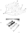
- the third assembly 300 shown in FIG. 6 has a planar structure by fitting the notches 12 of the braid 10 together. Various patterns can be obtained by combining many braided trees 10.
- a fourth assembly 400 shown in FIGS. 7 (a) and 7 (b) has a structure in which the notches 12 of the braid 10 are fitted to each other, and has a lifting structure. It is supported. By fitting the notches 12 together into a balanced structure, the user lifts the assembly 400 by gripping the end 401 as shown in FIGS. You can also. This structure cannot be realized with conventional blocks.
- the fifth assembly 500 shown in FIG. 8 is configured by fitting the notches 12 together, and has a stable structure despite the structure in which the rectangular parallelepipeds are arranged obliquely.
- the thin portions 15 of the pair of braided trees 10 are fitted into one notch 12 to form a stable structure and an asymmetric and eye-catching design.
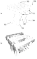
- a sixth assembly 600 shown in FIG. 9 is a small piece of furniture that is supposed to place a tablet terminal, and includes a cross-girder-shaped structure 601 and a support section that includes two braided trees 10 that support the structure 601 at an angle. 603.
- the structure 601 combines a total of eight braids 10 so that the thin portions 15 of the pair of braids 10 whose lower surfaces 18 are in contact with each other are sandwiched between the notches 12 of the pair of braids 10 facing each other. And has high rigidity.
- the support portion 603 is inserted through the central hole portion 602 of the structure 601, and the trunk portion 13 of the braid 10 constituting the structure 601 is fitted into the notch 12 of the brace 10 constituting the support portion 603.
- the front end portion 603a of the support portion 603 extends forward from the front surface of the structure 601, and the tablet terminal can be placed on the front end portion 603a.
- a seventh assembly 700 shown in FIG. 10 is medium-sized furniture that can be used as a stool.
- the thin-walled portions 15 of the pair of braids 10 constituting the girder 702 are fitted into the notches 12 of the leg portions 701 from the horizontal direction.
- the top plate 703 is formed by enhancing the rigidity and fitting the four braids 10 into the beam 702 from above.
- the braid 10 has a structure in which a pair of cutouts 12 are formed on both sides of the longitudinal direction DL of the columnar base material. Since a plurality of braids 10 can be connected by fitting into the end portion 11 or the trunk portion 13 or by fitting the notches 12 together, a complex assembly can be formed using a single simple braid 10. Can be formed.
- braids 10 having different materials.
- a balance can be achieved by using a metal or heavy metal braid 10 for the lower part of the object and using a wood or hollow light braid 10 for the upper part.
- the braid 10 can be produced by cutting out from the material, or can be produced by various known methods such as die casting.
- the braid according to the present invention can be used in the fields of braid play, object creation, and furniture.
Landscapes
- Life Sciences & Earth Sciences (AREA)
- Engineering & Computer Science (AREA)
- Wood Science & Technology (AREA)
- Toys (AREA)
Abstract
組木10は、同一形状及び同一寸法を有する他の組木と相互結合可能であって、所定方向に延びる柱状の基材の一側面17に一対の切り欠き12が対称に設けられている。端面16の幅及び厚さは等しく、端面16の幅をWとしたとき、所定方向における一側面17の長さは6Wであり、端面16から一方の切り欠き12までの距離はWであり、切り欠きの長さはWであり、切り欠きの深さはW/2である。
Description
本発明は、組木、それを利用した組立体及び家具に関するものである。
三角形、四角形、円形等の単純な幾何学的形状の立体物を積み上げる積み木という玩具が広く一般に親しまれている。積み木を用いて住居に類する構造物を作ることがあるが、積み木を積み上げて日本の住居で一般的な木造軸組みに類する構造物を作るのは困難である。また、積み木セットには複数形状の積み木が含まれるが、各形状の積み木の数によって創作の発想が制約されるという課題がある。
また、実用新案登録第3172064号公報には、直方体に近い外形を有する3種類の組木が開示されており、これらの組木を組み合わせることで複雑な組立体を得ることができるようになっている。
しかしながら、上述した従来の組木の外形は直方体に近く、軸組みを構成できる比率の形状ではない。また、組木が3種類ある為、種類ごとの組木の個数の上限により発想が制約される課題がある。
本発明の目的は、単純な構造でありながら木造軸組に類する組立体を得ることのできる組木と、これを用いた組立体及び家具の提供である。
本発明の一側面による組木は、同一形状及び同一寸法を有する他の組木と相互結合可能な組木であって、所定方向に延びる柱状の基材の一側面に一対の切り欠きが前記所定方向において対称に設けられ、前記基材の幅及び厚さは等しく、前記基材の幅をWとしたとき、前記所定方向における前記一側面の長さは6Wであり、前記所定方向において前記基材の端面から前記一対の切り欠きの一方までの距離はWであり、前記長手方向における各切り欠きの長さはWであり、各切り欠きの深さはW/2である。
前記組木は、前記一対の切り欠きが設けられた一対の薄肉部と、前記一対の薄肉部よりも厚さの厚い厚肉部と、を有し、前記薄肉部と前記厚肉部の何れかを前記他の組木の切り欠きに嵌めることにより前記他の組木と相互連結可能であるのが好ましい。
本発明の他の側面による組立体は、上記組木を複数個相互連結されて構成されている
本発明の更に他の側面による家具は、上記組立体の構造を有する。
本発明の更に他の側面による家具は、上記組立体の構造を有する。
本発明の一側面によれば、切り欠きが設けられた一種類の柱状の組木同士を組み合わせることができるので、単純な構造の組木でありながら、複雑な組立体を形作ることができる。また、組木を用いた組木遊び、オブジェクトの創作、家具の制作が可能である。
以下、添付図面を参照して、本発明の実施形態に係る組木について説明する。図1~図3に示すように、本実施形態の組木10は、長手方向DL(所定方向)に延びる柱状の基材の上面17(一側面)に一対の切り欠き12が左右対称に設けられたものであって、長手方向DLに沿って端から順に端部11、薄肉部15、胴部13、薄肉部15、及び端部11が一体に形成されている。一対の切り欠き12に対応する部分が一対の薄肉部15であり、一対の端部11,11及び胴部13は薄肉部15よりも厚さの厚い厚肉部である。
ここで、「長さ」とは長手方向DLにおける寸法を、「幅」とは幅方向DWにおける寸法を、「厚さ」又は「深さ」とは厚さ方向DTにおける寸法を意味する。
長手方向DLにおける組木10の端面16は略正四角形状を有し、端面16の幅及び厚さは等しい。端面16の幅をWとしたとき、各端部11の長さ、幅及び厚さは、全てWである。よって、長手方向DLにおける端面16から一方の切り欠き12までの距離もWである。胴部13の長さは2Wであり、幅及び厚さはWである。各切り欠き12の長さ及び幅はWであり、深さはW/2である。よって、薄肉部15の長さ及び幅はWであり、厚さはW/2である。
Wの具体的寸法はどのように設定してもよいが、組木10を玩具として用いる場合又は小型の家具に用いる場合には例えば3センチとし、中型の家具に用いる場合は例えば7センチとする。
なお、本発明の1側面においては、組木10の角部に面取りを施すのが好ましい。組木10の材料としては、木材、樹脂、金属、ガラスなど、多様なものが使用可能である。
次に、組木10を用いた組立体の例を説明する。なお、以下に説明する第1~第7の組立体100~700は全て、相互に連結された複数の組木10のみから構成されている。
図4に示す第1の組立体100は、複数の組木10を土台101、柱103、桁104、梁105に見立てて組み立てた木構軸組構造に類するものである。組立体100は次の様に作成できる。まず、4個の組木10の切り欠き12同士を嵌め合わせ、井桁形状を有する土台101を作成する。次に、一対の桁104に一対の梁105を連結させて、土台101と同一の井桁形状を有する組立体102を作成する。次に、土台101と組立体102とを4本の柱103で連結させる。この連結においては、柱103の切り欠き12に土台101及び組立体102の端部11を嵌め込めばよい。
組立体102に更に他の組木10を連結させれば、組立体100を更に垂直方向に拡張することができる。また、組立体100を複数個作成し、これら複数の組立体100を組木10を用いて左右方向に繋げば、水平方向に組立体100を拡張することもできる。
図5に示す第2の組立体200は、桁201に腕木202を直角方向に連結させた構造を有する。切り欠き12の幅が薄肉部15の長さと同じであり、また胴部13の長さは端部11の幅の2倍であることから、腕木202に庇203により上方から荷重が加わっても、一対の腕木202,202は端面同士が当接することで突っ張り、安定した構造を実現している。また、桁201は、腕木202の長さ方向中心よりも庇203から離隔する方向に偏倚した位置において腕木202を下方から支持しており、桁201を中心とする腕木202の左右の比率は積み木では実現不可能である。
図6に示す第3の組立体300は、組木10の切り欠き12同士を嵌め合わせて平面的な構造としたものである。多くの組木10を組み合わせることで多様な模様を得ることができる。
図7(a)及び図7(b)に示す第4の組立体400は、組木10の切り欠き12同士が嵌め合わせされて吊り上げの構造を有し、2本の脚部材Aにより下方から支持されている。切り欠き12同士を嵌め合わせてバランスの取れた構造とすることで、図7(c)及び図7(d)に示すように、使用者は端部401を把持して組立体400を持ち上げることもできる。この構造も従来の積み木では実現できない。
図8に示す第5の組立体500は、切り欠き12同士を嵌め合わせて構成されており、直方体を斜めに配置した構造であるにも関わらず安定した構造となっている。中段では、一対の組木10の薄肉部15が1つの切り欠き12に嵌め込まれ、安定した構造、且つ、非対称で目を引く意匠が構成されている。
図9に示す第6の組立体600は、タブレット端末を置く事を想定した小型の家具であって、井桁形状の構造601と、構造601を斜めに支える2個の組木10からなる支え部603と、を有する。構造601は、下面18同士を当接させた一対の組木10の薄肉部15を、相互に対向する一対の組木10の切り欠き12で挟み込むように、合計8個の組木10を組み合わせて形成されており、高い剛性を有する。支え部603は構造601の中央穴部602に挿通され、支え部603を構成する組木10の切り欠き12に構造601を構成する組木10の胴部13が嵌め込まれている。支え部603の前端部603aは構造601の前面よりも前方に延出しており、この前端部603aにタブレット端末を置くことができる。
図10に示す第7の組立体700は、スツールとして使える中型の家具であり、脚部701の切り欠き12に、桁702を構成する一対の組木10の薄肉部15を水平方向から嵌め込んで剛正を高め、桁702に4本の組木10を上方から嵌め込んで天板703を形成している。
このように、本発明の実施形態に係る組木10は、柱状の基材の長手方向DL両側に一対の切り欠き12が形成された構造を有し、切り欠き12に他の組木10の端部11や胴部13に嵌め込んだり切り欠き12同士を嵌め合わせたりして複数の組木10を連結できる寸法を有するので、単純な一種類の組木10を用いて複雑な組立体を形作ることができる。
なお、本発明の一側面においては、組木10に、色、模様、文字等などをつけるのが好ましい。この場合、組木10の面ごとに異なる色や模様等を付するのが好ましい。また、本発明の他の側面においては、組木10の表面に塗装等のコーティングを施す、又は異なる素材を張り付けるのが好ましい。
また、本発明の更に他の側面においては、必要に応じて組木10の中に金属等を入れて重量を重くする、或いは組木10を中空とすることで重量を軽くするのが好ましい。
本発明の他の側面においては、素材が異なる組木10を組み合わせるのが好ましい。この場合、オブジェクトの下段部分には金属製もしくは金属入りの重い組木10を使用し、上段部分には木材や中空の軽い組木10を使用することで、バランスを取ることができる。
組木10は、素材から削り出して制作することもでき、或いはダイキャストなど、公知の各種の方法により制作することもできる。
本発明は、上述した実施形態に限定されるものではなく、本発明の要旨を逸脱しない範囲内において種々の変更を加えることができる。
本発明に係る組木は、組木遊び、オブジェクトの創作、家具の分野に利用できる。
10:組木
11:端部
12:切り欠き
13:胴部
15:薄肉部
16:端面
17:上面
18:下面
100,200,300,400,500,600,700:組立体
11:端部
12:切り欠き
13:胴部
15:薄肉部
16:端面
17:上面
18:下面
100,200,300,400,500,600,700:組立体
Claims (4)
- 同一形状及び同一寸法を有する他の組木と相互結合可能な組木であって、
所定方向に延びる柱状の基材の一側面に一対の切り欠きが前記所定方向において対称に設けられ、
前記基材の幅及び厚さは等しく、
前記基材の幅をWとしたとき、前記所定方向における前記一側面の長さは6Wであり、前記所定方向において前記基材の端面から前記一対の切り欠きの一方までの距離はWであり、前記長手方向における各切り欠きの長さはWであり、各切り欠きの深さはW/2である組木。 - 前記一対の切り欠きが設けられた一対の薄肉部と、前記一対の薄肉部よりも厚さの厚い厚肉部と、を有し、前記薄肉部と前記厚肉部の何れかを前記他の組木の切り欠きに嵌めることにより前記他の組木と相互連結可能な請求項1に記載の組木。
- 相互連結された複数個の請求項2に記載の組木を有する組立体。
- 請求項3に記載の組立体の構造を有する家具。
Priority Applications (5)
| Application Number | Priority Date | Filing Date | Title |
|---|---|---|---|
| KR2020187000075U KR20180003204U (ko) | 2016-03-19 | 2017-02-23 | 나무 블럭, 그것을 이용한 조립체 및 가구 |
| EP17769786.9A EP3431160B1 (en) | 2016-03-19 | 2017-02-23 | Interlocking block |
| US16/081,186 US20190059578A1 (en) | 2016-03-19 | 2017-02-23 | Interlocking block, assembly using the same, and furniture |
| CN201790000688.0U CN209405686U (zh) | 2016-03-19 | 2017-02-23 | 木块、利用了该木块的组装体以及家具 |
| DE212017000089.9U DE212017000089U1 (de) | 2016-03-19 | 2017-02-23 | Verriegelungsblock, diesen verwendender Bausatz, und Möbel |
Applications Claiming Priority (2)
| Application Number | Priority Date | Filing Date | Title |
|---|---|---|---|
| JP2016001602U JP3205943U (ja) | 2016-03-19 | 2016-03-19 | 組木、それを利用した組立体及び家具 |
| JP2016-001602 | 2016-03-19 |
Publications (1)
| Publication Number | Publication Date |
|---|---|
| WO2017163740A1 true WO2017163740A1 (ja) | 2017-09-28 |
Family
ID=56741293
Family Applications (1)
| Application Number | Title | Priority Date | Filing Date |
|---|---|---|---|
| PCT/JP2017/006742 WO2017163740A1 (ja) | 2016-03-19 | 2017-02-23 | 組木、それを利用した組立体及び家具 |
Country Status (7)
| Country | Link |
|---|---|
| US (1) | US20190059578A1 (ja) |
| EP (1) | EP3431160B1 (ja) |
| JP (1) | JP3205943U (ja) |
| KR (1) | KR20180003204U (ja) |
| CN (1) | CN209405686U (ja) |
| DE (1) | DE212017000089U1 (ja) |
| WO (1) | WO2017163740A1 (ja) |
Cited By (2)
| Publication number | Priority date | Publication date | Assignee | Title |
|---|---|---|---|---|
| CN109224476A (zh) * | 2018-10-18 | 2019-01-18 | 武汉个个科技有限公司 | 连接装置及连接件 |
| JP2019078317A (ja) * | 2017-10-24 | 2019-05-23 | 渡 堀越 | 格子子を用いた格子群体の組み立て方法およびそれにより製作されたオブジェ |
Families Citing this family (3)
| Publication number | Priority date | Publication date | Assignee | Title |
|---|---|---|---|---|
| US11511210B2 (en) * | 2018-06-24 | 2022-11-29 | Daniel Gat | Cubic element for construction toys and a method for forming same |
| WO2021181168A1 (fr) * | 2020-03-11 | 2021-09-16 | Burdet Christopher | Siège à cadre modulaire |
| FR3119992A1 (fr) * | 2021-02-25 | 2022-08-26 | Nicolas Bôle | Jeu de construction à pièces emboitables |
Citations (5)
| Publication number | Priority date | Publication date | Assignee | Title |
|---|---|---|---|---|
| JPH022068U (ja) * | 1988-06-16 | 1990-01-09 | ||
| JP2006068188A (ja) * | 2004-09-01 | 2006-03-16 | Toshiaki Ozawa | 組立材、組立材セット及び骨組み構造体 |
| JP3172064U (ja) | 2011-09-20 | 2011-12-01 | 有限会社山下製作所 | 組木,それを利用した組立体及び家具 |
| JP3181308U (ja) * | 2012-11-16 | 2013-01-31 | 学 福岡 | 積木ユニット |
| WO2013078630A1 (zh) * | 2011-11-30 | 2013-06-06 | 大沣实业有限公司 | 一种益智积木构造 |
Family Cites Families (4)
| Publication number | Priority date | Publication date | Assignee | Title |
|---|---|---|---|---|
| US2059598A (en) * | 1935-10-31 | 1936-11-03 | Halsam Products Company | Toy building construction |
| GB890764A (en) * | 1960-02-22 | 1962-03-07 | Marler Haley Studios Ltd | Improvements in display stands having detachable and interfitting parts |
| US4039132A (en) * | 1976-01-05 | 1977-08-02 | Fournier Peter R | Plant support structure |
| IL53519A (en) * | 1977-12-02 | 1979-10-31 | Sofer N C | Toy building sets and elements therefor |
-
2016
- 2016-03-19 JP JP2016001602U patent/JP3205943U/ja active Active
-
2017
- 2017-02-23 WO PCT/JP2017/006742 patent/WO2017163740A1/ja active Application Filing
- 2017-02-23 DE DE212017000089.9U patent/DE212017000089U1/de not_active Expired - Lifetime
- 2017-02-23 EP EP17769786.9A patent/EP3431160B1/en active Active
- 2017-02-23 CN CN201790000688.0U patent/CN209405686U/zh active Active
- 2017-02-23 US US16/081,186 patent/US20190059578A1/en not_active Abandoned
- 2017-02-23 KR KR2020187000075U patent/KR20180003204U/ko not_active Application Discontinuation
Patent Citations (5)
| Publication number | Priority date | Publication date | Assignee | Title |
|---|---|---|---|---|
| JPH022068U (ja) * | 1988-06-16 | 1990-01-09 | ||
| JP2006068188A (ja) * | 2004-09-01 | 2006-03-16 | Toshiaki Ozawa | 組立材、組立材セット及び骨組み構造体 |
| JP3172064U (ja) | 2011-09-20 | 2011-12-01 | 有限会社山下製作所 | 組木,それを利用した組立体及び家具 |
| WO2013078630A1 (zh) * | 2011-11-30 | 2013-06-06 | 大沣实业有限公司 | 一种益智积木构造 |
| JP3181308U (ja) * | 2012-11-16 | 2013-01-31 | 学 福岡 | 積木ユニット |
Cited By (2)
| Publication number | Priority date | Publication date | Assignee | Title |
|---|---|---|---|---|
| JP2019078317A (ja) * | 2017-10-24 | 2019-05-23 | 渡 堀越 | 格子子を用いた格子群体の組み立て方法およびそれにより製作されたオブジェ |
| CN109224476A (zh) * | 2018-10-18 | 2019-01-18 | 武汉个个科技有限公司 | 连接装置及连接件 |
Also Published As
| Publication number | Publication date |
|---|---|
| DE212017000089U1 (de) | 2018-12-03 |
| EP3431160A1 (en) | 2019-01-23 |
| KR20180003204U (ko) | 2018-11-12 |
| JP3205943U (ja) | 2016-08-25 |
| CN209405686U (zh) | 2019-09-20 |
| EP3431160A4 (en) | 2019-09-25 |
| US20190059578A1 (en) | 2019-02-28 |
| EP3431160B1 (en) | 2021-05-26 |
Similar Documents
| Publication | Publication Date | Title |
|---|---|---|
| WO2017163740A1 (ja) | 組木、それを利用した組立体及び家具 | |
| US9345981B1 (en) | Multidimensional alignment spacing for toy building elements | |
| US20100056013A1 (en) | Magnetic Toy Construction Piece and Set | |
| US7731192B1 (en) | Balancing puzzle | |
| US20140120798A1 (en) | Stackable building block array | |
| JP3172064U (ja) | 組木,それを利用した組立体及び家具 | |
| KR200198228Y1 (ko) | 조립식 입체 판블록 | |
| US20060048475A1 (en) | Building block | |
| JP4734489B2 (ja) | 卍ブロック積み木 | |
| KR20070000067U (ko) | 조립 블럭 | |
| JP6951480B2 (ja) | 組部材 | |
| JP2023069563A (ja) | 棒状部材連結構造、この棒状部材連結構造を用いた構造物及びこの構造物を有する建築物 | |
| JP3241064U (ja) | 球体で構成される正四面体型立体パズル | |
| CN211863859U (zh) | 一种拼插积木套件 | |
| RU2785180C1 (ru) | Конструктор форм | |
| JP3206227U (ja) | 積み木 | |
| JP3120126U (ja) | 正六角形ゲームボードタイル | |
| KR200336550Y1 (ko) | 색상을 이용한 색상을 이용한 학습용 조형블럭 | |
| KR102044443B1 (ko) | 목재 결합 조인트 구조 | |
| TWM537928U (zh) | 積木結構 | |
| JP3203745U (ja) | パズル玩具 | |
| JP2024006607A (ja) | 木製棒状部材、部材セットおよび構造物 | |
| CN106555794A (zh) | 一种结构单元、空间单元及其多跨空间结构 | |
| JP2002200370A (ja) | 組立て遊戯具用ブロック | |
| JP5039812B2 (ja) | 木材製品、木材製品の製造方法 |
Legal Events
| Date | Code | Title | Description |
|---|---|---|---|
| ENP | Entry into the national phase |
Ref document number: 20187000075 Country of ref document: KR Kind code of ref document: U |
|
| WWE | Wipo information: entry into national phase |
Ref document number: 2017769786 Country of ref document: EP |
|
| 121 | Ep: the epo has been informed by wipo that ep was designated in this application |
Ref document number: 17769786 Country of ref document: EP Kind code of ref document: A1 |