WO2017163574A1 - 燃料噴射装置 - Google Patents
燃料噴射装置 Download PDFInfo
- Publication number
- WO2017163574A1 WO2017163574A1 PCT/JP2017/002045 JP2017002045W WO2017163574A1 WO 2017163574 A1 WO2017163574 A1 WO 2017163574A1 JP 2017002045 W JP2017002045 W JP 2017002045W WO 2017163574 A1 WO2017163574 A1 WO 2017163574A1
- Authority
- WO
- WIPO (PCT)
- Prior art keywords
- fuel injection
- injection device
- mover
- magnetic
- sectional area
- Prior art date
- Legal status (The legal status is an assumption and is not a legal conclusion. Google has not performed a legal analysis and makes no representation as to the accuracy of the status listed.)
- Ceased
Links
Images


Classifications
-
- F—MECHANICAL ENGINEERING; LIGHTING; HEATING; WEAPONS; BLASTING
- F02—COMBUSTION ENGINES; HOT-GAS OR COMBUSTION-PRODUCT ENGINE PLANTS
- F02M—SUPPLYING COMBUSTION ENGINES IN GENERAL WITH COMBUSTIBLE MIXTURES OR CONSTITUENTS THEREOF
- F02M51/00—Fuel-injection apparatus characterised by being operated electrically
- F02M51/06—Injectors peculiar thereto with means directly operating the valve needle
- F02M51/061—Injectors peculiar thereto with means directly operating the valve needle using electromagnetic operating means
- F02M51/0625—Injectors peculiar thereto with means directly operating the valve needle using electromagnetic operating means characterised by arrangement of mobile armatures
- F02M51/0664—Injectors peculiar thereto with means directly operating the valve needle using electromagnetic operating means characterised by arrangement of mobile armatures having a cylindrically or partly cylindrically shaped armature, e.g. entering the winding; having a plate-shaped or undulated armature entering the winding
-
- F—MECHANICAL ENGINEERING; LIGHTING; HEATING; WEAPONS; BLASTING
- F02—COMBUSTION ENGINES; HOT-GAS OR COMBUSTION-PRODUCT ENGINE PLANTS
- F02M—SUPPLYING COMBUSTION ENGINES IN GENERAL WITH COMBUSTIBLE MIXTURES OR CONSTITUENTS THEREOF
- F02M51/00—Fuel-injection apparatus characterised by being operated electrically
- F02M51/06—Injectors peculiar thereto with means directly operating the valve needle
- F02M51/061—Injectors peculiar thereto with means directly operating the valve needle using electromagnetic operating means
- F02M51/0625—Injectors peculiar thereto with means directly operating the valve needle using electromagnetic operating means characterised by arrangement of mobile armatures
- F02M51/0664—Injectors peculiar thereto with means directly operating the valve needle using electromagnetic operating means characterised by arrangement of mobile armatures having a cylindrically or partly cylindrically shaped armature, e.g. entering the winding; having a plate-shaped or undulated armature entering the winding
- F02M51/0671—Injectors peculiar thereto with means directly operating the valve needle using electromagnetic operating means characterised by arrangement of mobile armatures having a cylindrically or partly cylindrically shaped armature, e.g. entering the winding; having a plate-shaped or undulated armature entering the winding the armature having an elongated valve body attached thereto
-
- F—MECHANICAL ENGINEERING; LIGHTING; HEATING; WEAPONS; BLASTING
- F02—COMBUSTION ENGINES; HOT-GAS OR COMBUSTION-PRODUCT ENGINE PLANTS
- F02M—SUPPLYING COMBUSTION ENGINES IN GENERAL WITH COMBUSTIBLE MIXTURES OR CONSTITUENTS THEREOF
- F02M51/00—Fuel-injection apparatus characterised by being operated electrically
- F02M51/06—Injectors peculiar thereto with means directly operating the valve needle
- F02M51/061—Injectors peculiar thereto with means directly operating the valve needle using electromagnetic operating means
- F02M51/0689—Injectors peculiar thereto with means directly operating the valve needle using electromagnetic operating means and permanent magnets
-
- F—MECHANICAL ENGINEERING; LIGHTING; HEATING; WEAPONS; BLASTING
- F02—COMBUSTION ENGINES; HOT-GAS OR COMBUSTION-PRODUCT ENGINE PLANTS
- F02M—SUPPLYING COMBUSTION ENGINES IN GENERAL WITH COMBUSTIBLE MIXTURES OR CONSTITUENTS THEREOF
- F02M2200/00—Details of fuel-injection apparatus, not otherwise provided for
- F02M2200/02—Fuel-injection apparatus having means for reducing wear
-
- F—MECHANICAL ENGINEERING; LIGHTING; HEATING; WEAPONS; BLASTING
- F02—COMBUSTION ENGINES; HOT-GAS OR COMBUSTION-PRODUCT ENGINE PLANTS
- F02M—SUPPLYING COMBUSTION ENGINES IN GENERAL WITH COMBUSTIBLE MIXTURES OR CONSTITUENTS THEREOF
- F02M2200/00—Details of fuel-injection apparatus, not otherwise provided for
- F02M2200/07—Fuel-injection apparatus having means for avoiding sticking of valve or armature, e.g. preventing hydraulic or magnetic sticking of parts
-
- F—MECHANICAL ENGINEERING; LIGHTING; HEATING; WEAPONS; BLASTING
- F02—COMBUSTION ENGINES; HOT-GAS OR COMBUSTION-PRODUCT ENGINE PLANTS
- F02M—SUPPLYING COMBUSTION ENGINES IN GENERAL WITH COMBUSTIBLE MIXTURES OR CONSTITUENTS THEREOF
- F02M2200/00—Details of fuel-injection apparatus, not otherwise provided for
- F02M2200/08—Fuel-injection apparatus having special means for influencing magnetic flux, e.g. for shielding or guiding magnetic flux
Definitions
- the present invention relates to a fuel injection device used for an internal combustion engine, and more particularly to a fuel injection device that performs fuel injection by opening and closing a fuel passage by an electromagnetically driven mover.
- JP 2012-188977 as a background art in this technical field.
- a magnetic aperture whose inner diameter gradually increases toward the mover is provided on the inner circumferential surface of the magnetic core, so that the magnetism at the time of valve opening from when current is supplied to the electromagnetic coil until magnetic flux rises is provided. Delay time and the magnetic delay time when the valve is closed from when the current supply to the electromagnetic coil stops until the magnetic flux rises. It states that it can be improved (see summary).
- the fuel injection device When the fuel injection device is attached to a common rail filled with high pressure fuel, for example, in the case of the fuel injection device described in Patent Document 1, the direction in which the high fuel pressure closes the valve element that opens and closes the flow path. Act on.
- This fuel injection device generates a magnetic flux in a magnetic gap between the magnetic core and the mover by flowing an electric current through the electromagnetic coil, and thereby attracts the mover to the magnetic core by generating an electromagnetic attractive force.
- the electromagnetic attracting force generated by flowing the same current to the electromagnetic coil as before can not attract the mover to the magnetic core and can open the valve. There is a possibility that it cannot be done.
- the electromagnetic attraction force is small, the valve opening speed of the valve body is slow, and there is a possibility that the desired minute fuel cannot be injected.
- an object of the present invention is to provide a fuel injection device that makes the electromagnetic attractive force generated in the magnetic gap between the magnetic core and the mover equal to or greater than a desired value.
- the present invention provides a fuel injection device including a mover attracted by a magnetic core and a housing facing the mover in a direction orthogonal to the axial direction.
- the movable element is configured such that the length in the direction is 1.25 to 1.46 times the length in the axial direction of the housing.
- FIG. 1 shows a basic configuration of a fuel injection device according to Embodiment 1 of the present invention.
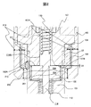
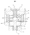
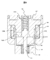
- 2 and 3 are partial enlarged views of the periphery of the drive unit structure of FIG. 1
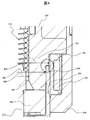
- FIG. 4 is an enlarged view of one side of the periphery of the drive unit structure
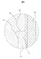
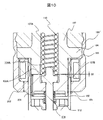
- FIG. 5 is an enlarged view of the junction in the magnetic circuit.
- valve element 114 is urged in the valve closing direction by the spring 110, and when the energization of the electromagnetic coil 105 is OFF, the fuel passage is closed and the energization of the electromagnetic coil 105 is turned ON. Then, the mover 102 is driven by electromagnetic attractive force to open the fuel passage and perform fuel injection.
- the magnetic core 107, the mover 102, the nozzle holder 101, and the housing 103 constitute a magnetic path.
- a throttle portion 213 is formed in a portion corresponding to the gap between the mover 102 and the magnetic core 107 of the nozzle holder 101.
- the electromagnetic coil 105 is attached to the outer peripheral side of the nozzle holder 101 while being wound around the bobbin 104, and maintains insulation by the resin molded body 121.
- the nozzle holder 101 includes a small-diameter cylindrical portion 22 having a small diameter and a large-diameter cylindrical portion 23 having a large diameter.
- a guide member 115 and an orifice cup 116 provided with the fuel injection port 10 are inserted and provided inside the distal end portion of the small diameter cylindrical portion 22.
- the guide member 115 is provided inside the orifice cup 116, and is fixed to the orifice cup 116 by press-fitting or plastic bonding, or has an integral structure with the orifice cup.
- the orifice cup 116 is welded and fixed to the distal end portion of the small diameter cylindrical portion 22 along the outer peripheral portion of the distal end surface.
- the guide member 115 guides the outer periphery 114B of the valve body provided at the distal end of the valve body 114 constituting the movable portion 106 described later.
- a conical valve seat 39 is formed on the orifice cup 116 on the side facing the guide member 115.
- a valve body 114B provided at the tip of the valve body 114 abuts on the valve seat 39 to guide or block the fuel flow to the fuel injection port 10.
- a groove is formed on the outer periphery of the nozzle holder 101, and a seal member 131 typified by a resin-made chip seal is fitted into the groove.
- a magnetic core 107 is press-fitted into the inner peripheral portion of the large-diameter cylindrical portion 23 of the nozzle holder 101 and welded and joined at the press-fit contact position, and a gap formed between the inside of the large-diameter cylindrical portion 23 and the outside air. Is sealed.
- a through hole (center hole) is provided at the center of the magnetic core 107, and fuel is guided to the through hole.
- Another member (adapter) 108 is press-fitted on the fuel supply port 118 side of the magnetic core 107 and welded and joined at the press-fitting contact position, and a gap formed between the inside and the outside air is sealed.
- a through hole is provided in the inner diameter of the adapter 108 in the same manner as the magnetic core 107, and communicates with the fuel supply port 118.
- the magnetic core 107 and the adapter 108 may have an integrated structure that communicates with a fuel supply port 118 provided at the upper end (the end opposite to the fuel injection port 10) of the fuel injection device.
- a filter 113 is provided inside the fuel supply port 118.
- a seal member 130 is provided on the outer peripheral side of the fuel supply port 118 to ensure liquid-tightness with the connecting portion on the fuel pipe side when connecting to the fuel pipe.
- FIG. 1 shows a normal state in which the electromagnetic coil 105 is not energized.
- the valve body 114 is biased by the spring 110 in the valve closing direction. Therefore, the seat 114B of the valve body 114 is in contact with the valve seat 39 of the orifice cup on the downstream side of the nozzle holder, and the fuel is sealed.
- the movable element 102 is supported by the valve body 114 and is urged in the valve opening direction by a zero spring 112 supported by the nozzle holder between the nozzle holder 101 and the movable element 102.
- the magnetic flux passing through the magnetic core 107 is a magnetic gap that flows toward the nozzle holder 101 at the position of the end surface of the magnetic core 107 on the mover 102 side and the magnetic gap between the magnetic core 107 and the mover 102 on the attracting surface side of the magnetic core 107. Is distributed to the magnetic flux flowing to the side. At this time, the number of magnetic fluxes passing between the magnetic core 107 and the mover 102 and the magnetic flux density determine the magnetic attractive force.
- the configuration of the movable portion 106 will be described with reference to an enlarged view of the drive portion structure in the valve closing state of the fuel injection device in FIG.
- the magnetic core 107 is press-fitted to the inner peripheral portion of the large-diameter cylindrical portion 23 of the nozzle holder 101 and is welded and joined at the press-fit contact position.
- the movable element 102 is enclosed in the large-diameter cylindrical portion 23 of the nozzle holder 101.
- the mover 102 In the normal state in which the fuel injection device is not energized, the mover 102 is biased toward the magnetic core 107 by receiving the biasing force of the zero spring 112.
- the magnetic core 107 is a component that attracts the mover 102 in the valve opening direction by applying a magnetic attraction force to the mover 102.
- the lower end surface (collision surface) 107B of the magnetic core 107 and the upper end surface (collision surface) 102B of the mover 102 may be appropriately plated to improve durability. Even when relatively soft soft magnetic stainless steel is used for the mover 102 and the magnetic core 107, durability reliability can be ensured by using hard chrome plating or electroless nickel plating.
- the through hole 107A provided as a fuel passage in the center of the magnetic core 107 has a diameter slightly larger than the diameter of the sliding portion 114A of the valve body 114.
- the lower end of the initial load setting spring 110 is in contact with the spring receiving surface formed on the upper end surface of the valve body 114.
- the other end of the spring 110 is received by a regulator 54 that is press-fitted into the through hole 108 ⁇ / b> A of the adapter 108.
- the spring 110 is fixed between the valve body 114 and the adjuster, and the initial load at which the spring 110 presses the valve body 114 against the valve seat 39 can be adjusted by adjusting the fixing position of the adjuster 54.
- the mover 102 is set in the large diameter cylindrical portion 23 of the nozzle holder 101, and the electromagnetic coil 105 and the housing 103 wound around the bobbin 104 are mounted on the outer periphery of the large diameter cylindrical portion 23 of the nozzle holder 101. Thereafter, the valve body 114 is inserted into the mover 102 through the through hole 108 ⁇ / b> A of the adapter 108 and the through hole 107 ⁇ / b> A of the fixed core 107.
- the movable body 106 is determined by determining the press-fitting position of the orifice cup 116 while detecting the stroke of the valve body 114 when the solenoid 114 is energized by pressing the valve body 114 to the closed position with a jig. Adjust the stroke to any position.
- the lower end surface 107B of the magnetic core 107 is configured to face the upper end surface 102A of the movable element 102 of the movable portion 106 with a stroke G1 of about 40 to 100 microns. Has been.
- a cup-shaped housing 103 is fixed to the outer periphery of the large-diameter cylindrical portion 23 of the nozzle holder 101.
- a through hole is provided in the center of the bottom of the housing 103, and the large diameter cylindrical portion 23 of the nozzle holder 101 is inserted through the through hole.
- a portion of the outer peripheral wall of the housing 103 forms an outer peripheral yoke portion facing the outer peripheral surface of the large-diameter cylindrical portion 23 of the nozzle holder 101.
- An annular or cylindrical electromagnetic coil 105 is disposed in a cylindrical space formed by the housing 103.
- the electromagnetic coil 105 is formed of an annular bobbin 104 having a U-shaped groove that opens outward in the radial direction, and a copper wire (electromagnetic coil 105) wound around the groove.
- a rigid conductor is fixed to the winding coil end and winding end of the electromagnetic coil 105, and is drawn from a through hole provided in the magnetic core 107.
- the outer periphery of the large-diameter cylindrical portion 23 of the conductor 109, the magnetic core 107, and the nozzle holder 101 is molded by injecting an insulating resin from the inner periphery of the upper end opening of the housing 103, and covered with the resin molded body 121.
- An annular magnetic passage is formed in the magnetic core 107, the mover 102, the large diameter cylindrical portion 23 of the nozzle holder 101, and the housing 103 so as to surround the electromagnetic coil 105.
- the fuel injection device of the present embodiment is not shown, it is attached to a common rail to which high pressure fuel is supplied from a high pressure fuel pump, and this high pressure fuel is directly injected into the cylinder of the internal combustion engine.
- the fuel pressure of the common rail has become as high as 20 MPa or more in order to meet the stricter exhaust gas regulations and the need for low fuel consumption. This fuel pressure is expected to increase further in the future, and a fuel injection device capable of stably injecting fuel in such a case is required.
- the axial length 201 of the mover 102 of the fuel injection device is 2.1 times the axial length 202 of the housing 103 facing the nozzle holder 101.
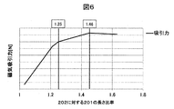
- FIG. 6 shows the relationship between the ratio of the axial length 201 of the mover to the axial length 202 of the housing 103 and the magnetic attractive force generated in the mover 102.
- the desired magnetic attraction force is 80 N in this embodiment as shown in FIG. 6, it cannot be obtained even if the applied current value is 20 A or more. That is, there is a possibility that the magnetic attractive force is insufficient and the valve cannot be opened. Therefore, even if the valve can be opened again, the valve opening speed is slow, so there is a possibility that the required minimum injection amount of fuel cannot be injected.
- the axial length 201 of the mover 102 of the fuel injection device in this embodiment is set to the axial length 202 of the housing 103 facing the nozzle holder 101. And 1.25 to 1.46 times. That is, the fuel injection device includes a mover 102 attracted by the magnetic core 107 and a housing 103 facing the mover 102 in a direction orthogonal to the axial direction, and the axial length 201 of the mover 102 is the housing 103.
- the movable element 102 and the housing 103 are configured so as to be 1.25 to 1.46 times the axial length 202.
- the axial length 201 of the mover 102 is 1.25 times or more the axial length 202 of the housing 103, the cross-sectional area of the mover 102 in the magnetic circuit can be secured.
- the magnetic resistance can be reduced, so that the magnetic attractive force generated in the mover 102 can be improved, and a desired magnetic attractive force 80N is ensured by applying a current value 19A as shown in FIG. It becomes possible.
- the magnetic attractive force tends not to increase.
- the mass of the mover 102 is increased. Since the increase in the mass of the mover 102 leads to deterioration of the response of the mover 102, the axial length 201 of the mover 102 is 1.46 times or less compared to the axial length 202 of the housing 103. Is desirable.
- the movable element 102 is generated such that the axial length 201 of the movable element 102 is 1.25 to 1.46 times the axial length 202 of the housing 103.
- the magnetic attractive force to be increased can be increased efficiently.
- the total area 203 on the outer peripheral side of the mover 102 of the fuel injection device of the present embodiment is the total axial sectional area of the housing 103 facing the large diameter cylindrical portion 23 of the nozzle holder 101. It is desirable that the ratio is 0.9 to 1.1 times that of 204.
- the magnetic attraction force reduces the magnetic resistance by ensuring that the entire outer peripheral side area 203 of the mover 102 is 0.9 times or more the entire axial sectional area 204 of the housing 103, and the magnetic attraction generated in the mover 102.
- the magnetic attraction force generated in the movable element 102 can be efficiently increased even with a smaller magnetomotive force than in the past.
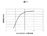
- the radial sectional area 212 of the housing 103 is compared with the radial sectional area 211 of the electromagnetic coil 105, the radial sectional area 212 of the housing 103 is larger than the radial sectional area 211 of the electromagnetic coil 105. Also, it is desirable to configure so as to be twice or more.
- FIG. 11 shows a comparison between the radial sectional area 212 of the housing 103 and the radial sectional area 211 of the electromagnetic coil 105 on the horizontal axis, and the magnetic attractive force in that case on the vertical axis.
- the increase in magnetic attraction force tends to slow down after the length ratio is doubled.
- by making the radial cross-sectional area of the housing 103 more than twice it is possible to reduce the magnetic resistance in the housing 103 and increase the magnetic attractive force generated between the magnetic core and the mover 102. .
- the cross-sectional area of the surface perpendicular to the axial direction of the valve body 114 of the magnetic core 107 which is the magnetic passage of the fuel injection device in the present embodiment decreases from the upstream side to the collision surface, and the cross-sectional area becomes one. It is desirable that the nozzle holder 101 be in contact with the largest part.
- the magnetic core 107 has a first portion 301 (large diameter portion) having a first horizontal cross-sectional area from the upper side at the axial position corresponding to the electromagnetic coil 105, A second portion 302 (medium diameter portion) having two horizontal cross-sectional areas and a third portion 303 (small diameter portion) having a third horizontal cross-sectional area.
- the cross-sectional area of the first part 301 (large diameter part) at the top is larger than the cross-sectional area of the second part 302 (medium diameter part), and the cross-sectional area of the third part 303 (small diameter part) is the second part. It is configured to be smaller than the cross-sectional area of 302 (medium diameter portion).
- FIG. 7 shows the distribution of magnetic flux density in the magnetic circuit of the present embodiment in shades of color. Note that components other than the magnetic core 107, the housing 103, the nozzle holder 101, the mover 102, and the electromagnetic coil 105 forming the magnetic circuit are not displayed in advance.
- the distribution of the magnetic flux density in the magnetic core 107 is highest in the third portion 303 (small diameter portion), and then the second portion 302 (medium diameter portion) shows a high value, and the first portion 301 (large diameter portion). Indicates the lowest value. Therefore, it is possible to reduce the magnetic resistance other than the attraction surface, the magnetic flux density is reduced, and further, the restriction of the cross-sectional area to the attraction surface promotes the increase of the magnetic flux density at the attraction surface, and the magnetic attraction force is efficiently increased. It is possible to improve, and it is possible to obtain a larger magnetic attractive force than before.
- the third portion 303 (small diameter portion) of the magnetic core 107 of the fuel injection device of the present embodiment has an outer peripheral surface at the same position as the outer peripheral surface 403 of the second portion 302 (medium diameter portion).
- the inner peripheral surface 401 of the third part 303 (small diameter part) is configured to spread toward the inner peripheral side over the inner peripheral surface 402 of the second part 302 (medium diameter part).
- the magnetic core 107 is configured such that the inner diameter gradually decreases from the end surface on the mover side toward the upstream side in the fuel flow direction, and the inner diameter portion 401 is, for example, a tapered surface.
- This feature makes it easier to obtain the effect of increasing the magnetic flux density on the attracting surface of the mover 102 by reducing the cross-sectional area on the attracting surface. As shown in FIG. 7, it is possible to improve the magnetic attractive force of the third portion 303 (small diameter portion) rather than the magnetic flux density of the second portion 302 (medium diameter portion). Further, since the inner diameter enlarged portion provided in the magnetic core 107 is configured so that the inner diameter increases in the downstream direction, a fluid passage can be secured between the magnetic core 107 and the valve body. When the fluid passage is insufficient, a throttle is formed when the fluid passes through the magnetic core 107 and the valve body, and the pressure loss increases. As a result, the maximum flow rate that can be injected decreases, making it difficult to inject the desired fuel.
- the magnetic core 107 is configured so that the inner peripheral surface 402 of the second part 302 (medium diameter part) is located at the same position as the inner peripheral surface of the first part 301 (large diameter part), and the second part 302 (medium part) It is desirable to configure the outer peripheral surface 404 of the first portion 301 (large diameter portion) so as to extend to the outer peripheral side from the outer peripheral surface 403 of the diameter portion.
- the magnetic flux density distribution in the magnetic core 107 is changed to the third portion 303 (small diameter) as shown in FIG. Part) is the highest, then the second part 302 (medium diameter part) shows the highest value, and the first part 301 (large diameter part) takes the lowest value. Therefore, it is possible to reduce the magnetic resistance of the magnetic core 107 other than the attracting surface, to reduce the magnetic flux density other than the attracting surface, and to efficiently increase the magnetic attracting force.
- the first portion 301 (large diameter portion) of the magnetic core 107 extends to the outer peripheral side of the second portion 302 (medium diameter portion) and covers the outer peripheral side of the mover 102.
- the large-diameter cylindrical portion 23 of 101 is in contact with and fixed to the outer peripheral enlarged portion 502 of the first portion 301 (large-diameter portion) of the magnetic core 107.
- the magnetic core 107 and the mover 102 that generate the magnetic attractive force need to secure an attractive area as much as possible. Therefore, it is desirable to make the nozzle holder 101 thin.
- a material having high strength is used for the nozzle holder 101.
- the nozzle holder 101 since a material with high strength is generally inferior in magnetic properties, the nozzle holder 101 must use a material inferior in magnetic properties. Therefore, the magnetic core 107 having excellent magnetic properties in the magnetic path is formed by expanding the first portion 301 (large diameter portion) of the magnetic core 107 to the outer peripheral side of the second portion 302 (small diameter portion) and abutting the nozzle holder. The cross-sectional area of the magnetic core 107 can be widened, and the magnetic resistance at the upstream portion of the magnetic core 107 can be reduced.
- the cross-sectional area of the third part 303 (small diameter part) is configured to be 0.78 to 0.85 times the cross-sectional area of the second part 302 (medium diameter part). .
- FIG. 7 it turns out that the magnetic flux density of the attraction
- a relief portion 501 for press-fitting the nozzle holder 101 may be configured from the first portion 301 (large diameter portion) to the second portion 302 (medium diameter portion) of the magnetic core 107.
- a machining R is generated at the upper end surface of the nozzle holder 101 and the corner of the magnetic core 107, so it is necessary to provide relief at the contact portion. .
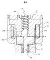
- FIG. 8 shows a state where the mover 102 is attracted by the magnetic attraction force and collides with the lower surface 107B of the magnetic core 107.
- the seat 114B of the valve body 114 is separated from the valve seat 39 of the orifice cup 116, and the supplied fuel is injected from the plurality of injection holes.
- the number of injection holes may be a single hole.
- FIG. 5 shows a state in which the movable portion 106 starts to perform a valve closing motion from the valve open state, and a gap as indicated by G2 is formed between the mover and the magnetic core 107.
- the fuel injection device of the present embodiment be applied to a type in which the fuel is directly injected into the engine with a supercharger. Since recent engines are required to be downsized, it is desirable to have a supercharger.
- Fuel supply port 121 Molded resin 130 ... Sealing material 131 ... Sealing member 201 ... Length of housing axial direction 202 ... Length of housing axial direction 203 ... Movable element Side area 204 ... Housing axial sectional area 211 ... Radial sectional area 212 of the electromagnetic coil ... Radial sectional view of the housing Reference numeral 213... Restricted portion 301... First portion (large diameter portion) 302 of the magnetic core 302. Second portion (medium diameter portion) of the magnetic core 303. Third portion (small diameter portion) 401 of the magnetic core 401.
Landscapes
- Engineering & Computer Science (AREA)
- Chemical & Material Sciences (AREA)
- Combustion & Propulsion (AREA)
- Mechanical Engineering (AREA)
- General Engineering & Computer Science (AREA)
- Physics & Mathematics (AREA)
- Electromagnetism (AREA)
- Fuel-Injection Apparatus (AREA)
Abstract
Description
ハウジング103によって形成される筒状空間内には環状若しくは筒状の電磁コイル105が配置されている。電磁コイル105は半径方向外側に向かって開口する断面がU字状の溝を持つ環状のボビン104と、この溝の中に巻きつけられた銅線(電磁コイル105)で形成される。電磁コイル105の巻き始めと巻き終わりの端部には剛性のある導体が固定されており、磁気コア107に設けた貫通孔より引き出されている。この導体109と磁気コア107、ノズルホルダ101の大径筒部23の外周はハウジング103の上端開口部内周から絶縁樹脂を注入して、モールド成形され、樹脂成形体121で覆われる。電磁コイル105を囲むようにして、磁気コア107、可動子102、ノズルホルダ101の大径筒状部23及びハウジング103の部分に環状の磁気通路が形成される。
Claims (10)
- 磁性コアに吸引される可動子と、前記可動子と軸方向と直交する方向において対向するハウジングと、を備えた燃料噴射装置において、
前記可動子の軸方向長さは前記ハウジングの軸方向長さに対して、1.25~1.46倍となるように前記可動子を構成することを特徴とする燃料噴射装置。 - 請求項1に記載の燃料噴射装置において、前記可動子の側面積は前記磁性部の軸方向断面積に対して、0.9~1.1倍となるように前記可動子を構成することを特徴とする燃料噴射装置。
- 請求項1に記載の燃料噴射装置において、
前記磁性部の内側に設けられるコイルを備え、前記可動子と衝突する前記磁性コアの下面は、前記コイルの下端と対応する位置に配置されるか、又は前記コイルの下端と対応する位置よりも下側に配置されることを特徴とする燃料噴射装置。 - 請求項1に記載の燃料噴射装置において、
前記ハウジングの径方向断面積が、前記ハウジングに内包される電磁コイルの径方向断面積と比較して2倍以上となるように前記ハウジングを構成することを特徴とする燃料噴射装置。 - 磁性コアに吸引される可動子と、前記可動子と軸方向において対向する磁性部と、を備えた燃料噴射装置において、
磁性コアは、電磁コイルに対応する軸方向の位置において、上側から第1の水平方向断面積を有する第1部位、第2の水平方向断面積を有する第2部位、第3の水平方向断面積を有する第3部位を有し、第1部位の断面積は第2部位の断面積よりも大きく、第3部位の断面積は第2部位の断面積よりも小さくなるように構成されることを特徴とする燃料噴射装置。 - 請求項5に記載の燃料噴射装置において、
前記第3部位の外周面は前記第2部位の外周面と同じ位置となるように形成され、前記第3部位の内周面から前記第2部位の内周面にかけて内周側に広がるように形成されることを特徴とする燃料噴射装置。 - 請求項6に記載の燃料噴射装置において、
前記第2部位の内周面は前記第1部位の内周面と同じ位置となるように形成され、前記第2部位の外周面から前記第1部位の外周面にかけて外周側に広がるように形成されることを特徴とする燃料噴射装置。 - 請求項5に記載の燃料噴射装置において、
前記第2部位の外周面から前記第1部位の外周面にかけて外周側に広がるように形成され、かつ、前記可動子の外周側を覆うノズルが前記第1部位の外周への拡大部に突き当たることで固定されることを特徴とする燃料噴射装置。 - 請求項1又は5に記載の燃料噴射装置において、
前記第3部位の断面積は前記第2部位の断面積に対して0.78倍~0.85倍となるように構成することを特徴とする燃料噴射装置。 - 請求項1に記載されている燃料噴射装置において、磁性コアの内径は前記可動子との衝突面に向かって外周側に傾斜するように構成されることを特徴とする燃料噴射装置。
Priority Applications (4)
| Application Number | Priority Date | Filing Date | Title |
|---|---|---|---|
| CN201780007104.7A CN108779747B (zh) | 2016-03-25 | 2017-01-23 | 燃料喷射装置 |
| US15/779,198 US20210207566A1 (en) | 2016-03-25 | 2017-01-23 | Fuel injection device |
| DE112017000218.4T DE112017000218B4 (de) | 2016-03-25 | 2017-01-23 | Kraftstoffeinspritzvorrichtung |
| JP2018507071A JP6595701B2 (ja) | 2016-03-25 | 2017-01-23 | 燃料噴射装置 |
Applications Claiming Priority (2)
| Application Number | Priority Date | Filing Date | Title |
|---|---|---|---|
| JP2016061081 | 2016-03-25 | ||
| JP2016-061081 | 2016-03-25 |
Publications (1)
| Publication Number | Publication Date |
|---|---|
| WO2017163574A1 true WO2017163574A1 (ja) | 2017-09-28 |
Family
ID=59901121
Family Applications (1)
| Application Number | Title | Priority Date | Filing Date |
|---|---|---|---|
| PCT/JP2017/002045 Ceased WO2017163574A1 (ja) | 2016-03-25 | 2017-01-23 | 燃料噴射装置 |
Country Status (5)
| Country | Link |
|---|---|
| US (1) | US20210207566A1 (ja) |
| JP (1) | JP6595701B2 (ja) |
| CN (1) | CN108779747B (ja) |
| DE (1) | DE112017000218B4 (ja) |
| WO (1) | WO2017163574A1 (ja) |
Cited By (1)
| Publication number | Priority date | Publication date | Assignee | Title |
|---|---|---|---|---|
| WO2019092875A1 (ja) * | 2017-11-13 | 2019-05-16 | 三菱電機株式会社 | 燃料噴射弁 |
Citations (8)
| Publication number | Priority date | Publication date | Assignee | Title |
|---|---|---|---|---|
| JP2010059898A (ja) * | 2008-09-05 | 2010-03-18 | Hitachi Automotive Systems Ltd | 燃料噴射弁及び2部品の結合方法 |
| JP2011052557A (ja) * | 2009-08-31 | 2011-03-17 | Hitachi Automotive Systems Ltd | 燃料噴射弁 |
| JP2013068228A (ja) * | 2013-01-25 | 2013-04-18 | Denso Corp | 燃料噴射弁 |
| JP2013072298A (ja) * | 2011-09-27 | 2013-04-22 | Hitachi Automotive Systems Ltd | 燃料噴射弁 |
| JP2013104340A (ja) * | 2011-11-11 | 2013-05-30 | Keihin Corp | 電磁式燃料噴射弁 |
| JP2013160083A (ja) * | 2012-02-02 | 2013-08-19 | Hitachi Automotive Systems Ltd | 電磁式燃料噴射弁 |
| WO2013121806A1 (ja) * | 2012-02-13 | 2013-08-22 | 株式会社ケーヒン | 燃料噴射弁 |
| JP2013217307A (ja) * | 2012-04-10 | 2013-10-24 | Denso Corp | 燃料噴射弁 |
Family Cites Families (3)
| Publication number | Priority date | Publication date | Assignee | Title |
|---|---|---|---|---|
| DE19708104A1 (de) * | 1997-02-28 | 1998-09-03 | Bosch Gmbh Robert | Magnetventil |
| JP4161217B2 (ja) * | 2003-12-26 | 2008-10-08 | 株式会社デンソー | 燃料噴射弁 |
| JP5537472B2 (ja) * | 2011-03-10 | 2014-07-02 | 日立オートモティブシステムズ株式会社 | 燃料噴射装置 |
-
2017
- 2017-01-23 US US15/779,198 patent/US20210207566A1/en not_active Abandoned
- 2017-01-23 DE DE112017000218.4T patent/DE112017000218B4/de active Active
- 2017-01-23 CN CN201780007104.7A patent/CN108779747B/zh active Active
- 2017-01-23 JP JP2018507071A patent/JP6595701B2/ja active Active
- 2017-01-23 WO PCT/JP2017/002045 patent/WO2017163574A1/ja not_active Ceased
Patent Citations (8)
| Publication number | Priority date | Publication date | Assignee | Title |
|---|---|---|---|---|
| JP2010059898A (ja) * | 2008-09-05 | 2010-03-18 | Hitachi Automotive Systems Ltd | 燃料噴射弁及び2部品の結合方法 |
| JP2011052557A (ja) * | 2009-08-31 | 2011-03-17 | Hitachi Automotive Systems Ltd | 燃料噴射弁 |
| JP2013072298A (ja) * | 2011-09-27 | 2013-04-22 | Hitachi Automotive Systems Ltd | 燃料噴射弁 |
| JP2013104340A (ja) * | 2011-11-11 | 2013-05-30 | Keihin Corp | 電磁式燃料噴射弁 |
| JP2013160083A (ja) * | 2012-02-02 | 2013-08-19 | Hitachi Automotive Systems Ltd | 電磁式燃料噴射弁 |
| WO2013121806A1 (ja) * | 2012-02-13 | 2013-08-22 | 株式会社ケーヒン | 燃料噴射弁 |
| JP2013217307A (ja) * | 2012-04-10 | 2013-10-24 | Denso Corp | 燃料噴射弁 |
| JP2013068228A (ja) * | 2013-01-25 | 2013-04-18 | Denso Corp | 燃料噴射弁 |
Cited By (2)
| Publication number | Priority date | Publication date | Assignee | Title |
|---|---|---|---|---|
| WO2019092875A1 (ja) * | 2017-11-13 | 2019-05-16 | 三菱電機株式会社 | 燃料噴射弁 |
| JPWO2019092875A1 (ja) * | 2017-11-13 | 2020-02-06 | 三菱電機株式会社 | 燃料噴射弁 |
Also Published As
| Publication number | Publication date |
|---|---|
| DE112017000218T5 (de) | 2018-08-16 |
| US20210207566A1 (en) | 2021-07-08 |
| DE112017000218B4 (de) | 2025-09-25 |
| CN108779747A (zh) | 2018-11-09 |
| CN108779747B (zh) | 2021-05-28 |
| JPWO2017163574A1 (ja) | 2018-10-18 |
| JP6595701B2 (ja) | 2019-10-23 |
Similar Documents
| Publication | Publication Date | Title |
|---|---|---|
| US7775463B2 (en) | Electromagnetic fuel injection valve | |
| JP4935882B2 (ja) | 燃料噴射弁 | |
| JP5152024B2 (ja) | 燃料噴射弁 | |
| CN103016226A (zh) | 燃料喷射阀 | |
| CN101506510A (zh) | 燃料喷射阀 | |
| JP2012188977A (ja) | 燃料噴射装置 | |
| JP5482267B2 (ja) | 燃料噴射弁 | |
| JP2010138886A (ja) | 燃料噴射弁 | |
| JP2011094632A (ja) | 電磁燃料噴射弁及びその組立て方法 | |
| JP4453745B2 (ja) | 燃料噴射弁 | |
| JP4120632B2 (ja) | 燃料噴射弁 | |
| JP6595701B2 (ja) | 燃料噴射装置 | |
| JP3923935B2 (ja) | 燃料噴射弁 | |
| JP4577654B2 (ja) | 電磁駆動装置およびこれを用いた燃料噴射弁 | |
| JP6275902B2 (ja) | 燃料噴射装置 | |
| JP2013064414A (ja) | 燃料噴射弁 | |
| JPWO2019163383A1 (ja) | 燃料噴射弁及びその組立方法 | |
| JP2010159677A (ja) | 燃料噴射弁 | |
| JPWO2019054036A1 (ja) | 流量制御装置、および流量制御装置の製造方法 | |
| JP6453381B2 (ja) | 燃料噴射装置 | |
| JP5152052B2 (ja) | 燃料噴射装置 | |
| JP5251468B2 (ja) | 燃料噴射弁 | |
| JP2013068228A (ja) | 燃料噴射弁 | |
| JP2005083201A (ja) | 燃料噴射弁 | |
| JP5126121B2 (ja) | 燃料噴射弁 |
Legal Events
| Date | Code | Title | Description |
|---|---|---|---|
| ENP | Entry into the national phase |
Ref document number: 2018507071 Country of ref document: JP Kind code of ref document: A |
|
| WWE | Wipo information: entry into national phase |
Ref document number: 112017000218 Country of ref document: DE |
|
| 121 | Ep: the epo has been informed by wipo that ep was designated in this application |
Ref document number: 17769621 Country of ref document: EP Kind code of ref document: A1 |
|
| 122 | Ep: pct application non-entry in european phase |
Ref document number: 17769621 Country of ref document: EP Kind code of ref document: A1 |
|
| WWG | Wipo information: grant in national office |
Ref document number: 112017000218 Country of ref document: DE |