WO2017163479A1 - Load detection device - Google Patents
Load detection device Download PDFInfo
- Publication number
- WO2017163479A1 WO2017163479A1 PCT/JP2016/082850 JP2016082850W WO2017163479A1 WO 2017163479 A1 WO2017163479 A1 WO 2017163479A1 JP 2016082850 W JP2016082850 W JP 2016082850W WO 2017163479 A1 WO2017163479 A1 WO 2017163479A1
- Authority
- WO
- WIPO (PCT)
- Prior art keywords
- load detection
- electrode
- detection sensor
- elastic support
- sheet
- Prior art date
Links
- 238000001514 detection method Methods 0.000 title claims abstract description 277
- 239000002184 metal Substances 0.000 claims description 105
- 229910052751 metal Inorganic materials 0.000 claims description 105
- 125000006850 spacer group Chemical group 0.000 claims description 22
- 239000000758 substrate Substances 0.000 description 35
- 230000008859 change Effects 0.000 description 18
- 230000002159 abnormal effect Effects 0.000 description 13
- NJPPVKZQTLUDBO-UHFFFAOYSA-N novaluron Chemical compound C1=C(Cl)C(OC(F)(F)C(OC(F)(F)F)F)=CC=C1NC(=O)NC(=O)C1=C(F)C=CC=C1F NJPPVKZQTLUDBO-UHFFFAOYSA-N 0.000 description 13
- 238000010586 diagram Methods 0.000 description 9
- 239000000463 material Substances 0.000 description 9
- 239000011347 resin Substances 0.000 description 9
- 229920005989 resin Polymers 0.000 description 9
- 230000007613 environmental effect Effects 0.000 description 6
- 229920001707 polybutylene terephthalate Polymers 0.000 description 5
- 230000035945 sensitivity Effects 0.000 description 5
- 238000000034 method Methods 0.000 description 4
- 230000000149 penetrating effect Effects 0.000 description 4
- 238000005452 bending Methods 0.000 description 3
- 239000004642 Polyimide Substances 0.000 description 2
- 230000004308 accommodation Effects 0.000 description 2
- 230000006866 deterioration Effects 0.000 description 2
- 238000007599 discharging Methods 0.000 description 2
- 239000003822 epoxy resin Substances 0.000 description 2
- WABPQHHGFIMREM-UHFFFAOYSA-N lead(0) Chemical compound [Pb] WABPQHHGFIMREM-UHFFFAOYSA-N 0.000 description 2
- 239000012528 membrane Substances 0.000 description 2
- 150000002739 metals Chemical class 0.000 description 2
- 238000000465 moulding Methods 0.000 description 2
- 230000002093 peripheral effect Effects 0.000 description 2
- 239000005011 phenolic resin Substances 0.000 description 2
- 229920000647 polyepoxide Polymers 0.000 description 2
- 229920001721 polyimide Polymers 0.000 description 2
- RYGMFSIKBFXOCR-UHFFFAOYSA-N Copper Chemical compound [Cu] RYGMFSIKBFXOCR-UHFFFAOYSA-N 0.000 description 1
- 239000000853 adhesive Substances 0.000 description 1
- 230000001070 adhesive effect Effects 0.000 description 1
- 229910052802 copper Inorganic materials 0.000 description 1
- 239000010949 copper Substances 0.000 description 1
- 238000009413 insulation Methods 0.000 description 1
- 238000012423 maintenance Methods 0.000 description 1
- 238000012986 modification Methods 0.000 description 1
- 230000004048 modification Effects 0.000 description 1
- 230000035515 penetration Effects 0.000 description 1
- -1 polybutylene terephthalate Polymers 0.000 description 1
- 229920000515 polycarbonate Polymers 0.000 description 1
- 239000004417 polycarbonate Substances 0.000 description 1
- 230000008569 process Effects 0.000 description 1
- 230000004044 response Effects 0.000 description 1
- 238000000926 separation method Methods 0.000 description 1
- 238000005549 size reduction Methods 0.000 description 1
- 229910001220 stainless steel Inorganic materials 0.000 description 1
- 239000010935 stainless steel Substances 0.000 description 1
- 229920002803 thermoplastic polyurethane Polymers 0.000 description 1
Images


Classifications
-
- B—PERFORMING OPERATIONS; TRANSPORTING
- B60—VEHICLES IN GENERAL
- B60N—SEATS SPECIALLY ADAPTED FOR VEHICLES; VEHICLE PASSENGER ACCOMMODATION NOT OTHERWISE PROVIDED FOR
- B60N2/00—Seats specially adapted for vehicles; Arrangement or mounting of seats in vehicles
- B60N2/002—Seats provided with an occupancy detection means mounted therein or thereon
-
- B—PERFORMING OPERATIONS; TRANSPORTING
- B60—VEHICLES IN GENERAL
- B60N—SEATS SPECIALLY ADAPTED FOR VEHICLES; VEHICLE PASSENGER ACCOMMODATION NOT OTHERWISE PROVIDED FOR
- B60N2/00—Seats specially adapted for vehicles; Arrangement or mounting of seats in vehicles
- B60N2/70—Upholstery springs ; Upholstery
- B60N2/7094—Upholstery springs
-
- B—PERFORMING OPERATIONS; TRANSPORTING
- B60—VEHICLES IN GENERAL
- B60N—SEATS SPECIALLY ADAPTED FOR VEHICLES; VEHICLE PASSENGER ACCOMMODATION NOT OTHERWISE PROVIDED FOR
- B60N2/00—Seats specially adapted for vehicles; Arrangement or mounting of seats in vehicles
- B60N2/90—Details or parts not otherwise provided for
-
- G—PHYSICS
- G05—CONTROLLING; REGULATING
- G05B—CONTROL OR REGULATING SYSTEMS IN GENERAL; FUNCTIONAL ELEMENTS OF SUCH SYSTEMS; MONITORING OR TESTING ARRANGEMENTS FOR SUCH SYSTEMS OR ELEMENTS
- G05B19/00—Programme-control systems
- G05B19/02—Programme-control systems electric
- G05B19/18—Numerical control [NC], i.e. automatically operating machines, in particular machine tools, e.g. in a manufacturing environment, so as to execute positioning, movement or co-ordinated operations by means of programme data in numerical form
- G05B19/406—Numerical control [NC], i.e. automatically operating machines, in particular machine tools, e.g. in a manufacturing environment, so as to execute positioning, movement or co-ordinated operations by means of programme data in numerical form characterised by monitoring or safety
-
- H—ELECTRICITY
- H01—ELECTRIC ELEMENTS
- H01H—ELECTRIC SWITCHES; RELAYS; SELECTORS; EMERGENCY PROTECTIVE DEVICES
- H01H13/00—Switches having rectilinearly-movable operating part or parts adapted for pushing or pulling in one direction only, e.g. push-button switch
- H01H13/02—Details
- H01H13/12—Movable parts; Contacts mounted thereon
- H01H13/14—Operating parts, e.g. push-button
- H01H13/16—Operating parts, e.g. push-button adapted for operation by a part of the human body other than the hand, e.g. by foot
Definitions
- the present invention relates to a load detection device and is suitable for detecting a load applied according to seating or the like.
- an alarm system that warns that a seat belt is not worn when riding is put into practical use.
- a warning is issued when the seat belt is not detected while a person is seated.
- a load detection device that detects a load applied in accordance with the seating may be used.
- Some of such load detection devices are arranged under the seat cushion of the seat.
- the seat cushion In the seat, there are a case where the seat cushion is arranged on the seat pan and a case where the seat cushion is arranged on a plurality of S springs fixed to the frame.
- the load detection device In a seat in which a seat cushion is disposed on a plurality of S springs, the load detection device may be used while being locked to the S springs.
- Patent Document 1 listed below describes such a load detection device.
- the load detection device described in Patent Literature 1 includes a pedestal that is locked to an S spring, and a membrane switch that is disposed on the pedestal via a spacer.
- the following configuration can be considered. That is, it is conceivable to provide the switch with a pressing member that turns on the load detection sensor when the pressure receiving surface that receives the pressure from the seat cushion of the seat is pressed.
- the pressure member becomes unstable due to the movement of the pressing member, and there is a concern that abnormal noise may occur due to contact with other members according to the movement of the pressing member.
- an object of the present invention is to provide a load detection device that can appropriately detect a load while suppressing the occurrence of abnormal noise.
- a load detection device has a load detection sensor and a pressure receiving surface that receives pressure from a seat cushion, and the load detection sensor is configured by pressing the pressure receiving surface against the seat cushion.
- a pressing member for pressing and an elastic support portion for supporting the pressing member from the load detection sensor side are provided.
- a pressure detection surface of the pressing member is opposed to the lower surface of a seat cushion such as a seat or a bed, and the pressure detection member is pressed from the pressing member.
- an elastic support part to support. Since the pressing member is supported from the load detection sensor side by the elastic support portion, when the load is not applied to the load detection sensor, the pressing member moves and contacts other members, and abnormal noise caused by the contact is generated. Occurrence can be prevented. Further, the movement when the pressing member presses the load detection sensor in response to the pressing from the seat cushion is also alleviated.
- the load detection device can appropriately detect the load while suppressing the occurrence of abnormal noise.
- the said pressure receiving surface moves with respect to the said mounting surface so that the angle with respect to the mounting surface in which the said load detection sensor is mounted changes.
- the pressure receiving surface can follow the inclination. Therefore, the pressure receiving surface is appropriately pressed against the lower surface of the seat cushion, and the load can be detected appropriately.
- the load detection sensor includes: a first electrode sheet including at least one first electrode; and a second electrode that is disposed closer to the pressing member than the first electrode sheet and faces the first electrode.
- the second electrode sheet includes a metal plate on the pressing member side, and a part of the metal plate is used as the elastic support portion.
- the second electrode sheet since the second electrode sheet includes a metal plate on the pressing member side, the flexibility does not easily change even when the temperature changes. Therefore, even when the environmental temperature around the load detection device changes, the bending method of the metal plate pressed by the pressing member is hardly changed. Moreover, since a part of metal plate is an elastic support part, even when the environmental temperature around a load detection apparatus changes, the elastic force of an elastic support part does not change easily. Therefore, according to the load detection device, erroneous detection such as seating can be suppressed even when the environmental temperature changes.
- the second electrode sheet is made of a metal plate, and a portion of the metal plate that faces the first electrode through the opening is the second electrode, and the other portion of the metal plate is the elastic support. It is preferable to be a part.
- the metal plate plays a role as an electrode constituting one of the switches and a role as a support portion for supporting the pressing member. For this reason, it is possible to appropriately detect the load while suppressing the generation of abnormal noise while suppressing the number of parts of the load detection sensor.
- the second electrode sheet includes an insulating sheet on which the second electrode is provided and the metal plate disposed on a surface of the insulating sheet on the pressing member side.
- the load detection device can be reduced in size and space.
- connection maintaining unit that maintains electrical connection even when an external pressure is not applied between a part of the first electrode sheet and a part of the second electrode sheet is configured, and the first component that configures the connection maintaining unit It is preferable that a part of the two-electrode sheet also serves as the elastic support portion.
- the circuit formed on the first electrode sheet and the circuit formed on the second electrode sheet are always in a conductive state via the connection maintaining unit. For this reason, even when the number of switches connected in series in the circuit in the load detection sensor is an odd number, in the load detection sensor, only one of the first electrode sheet and the second electrode sheet is used as the pair of terminals of the circuit. Can be arranged.
- a part of the second electrode sheet constituting the connection maintaining portion also serves as an elastic support portion, a force acts on the elastic support portion on the first electrode sheet side as a repulsive force, and the connection maintaining portion is configured. A force acts on the first electrode sheet side also in a part of the two-electrode sheet.
- connection state of a connection maintenance part can be made stronger.
- the metal plate plays a role of arranging the pair of terminals on one electrode sheet and a role as a support portion for supporting the pressing member. For this reason, it is possible to appropriately detect the load while suppressing the generation of abnormal noise while suppressing the number of parts of the load detection sensor.
- the elastic support part is a plate-like member made of metal provided between the load detection sensor and the pressing member, and the plate-like member is curved in an arch shape toward the pressing member side, and the plate It is preferable that the entire member is the elastic support portion.
- the pressing member that presses the load detection sensor by being pressed by the seat cushion is supported by a plate-like member that curves in an arch shape toward the pressing member side. For this reason, the change in the load applied to the load detection sensor from the pressing member is likely to depend on the plate-like member that supports the pressing member. Further, since this plate-like member is made of metal, it is difficult to reduce deterioration as compared with the case of being made of resin or the like. Therefore, even if the pressing member is continuously pressed from the seat cushion for a long period of time, a change in load applied from the pressing member to the load detection sensor can be reduced by the plate-like member. As a result, the load can be detected appropriately.
- the plate-like member is formed of a bimetal that is deformed so as to be separated from the insulating sheet as the temperature rises.
- the insulation sheet is easily deformed as the temperature rises, and the load detection sensor is easily turned on with a weak force as the temperature rises.
- Metals do not change flexibility even when the temperature changes, but the flexibility does not change at all. For this reason, if the metal plate is formed of a bimetal that is deformed so as to move away from the insulating sheet as the temperature rises, when the temperature rises, the insulating sheet is easily bent or the load detection sensor is turned on with a weak force. It is possible to suppress a change in load detection due to the ease and the separation of the metal plate from the insulating sheet. Therefore, the load can be detected more appropriately.
- the portion where the elastic support portion supports the pressing member is located above the load detection sensor.
- the size can be reduced as compared with the case where the elastic support portion supports the pressing member below the load detection sensor.
- FIG. 6 is a cross-sectional view taken along line XX of the load detection sensor of FIG. 5.
- FIG. 6 is a cross-sectional view taken along line YY of the load detection sensor of FIG. 5.
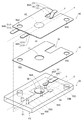
- FIG. 1 is an exploded view showing a configuration of a load detection device in the first embodiment
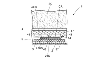
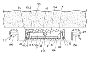
- FIG. 2 is a cross section showing a state in which the load detection device 1 is attached to an S spring of a seat device.
- FIG. FIG. 2 is a cross-sectional view of the load detection device 1 on a surface along the left-right direction of the seat device, and the load detection sensor 5 is simplified in order to avoid complication of the drawing.
- the load detection device 1 includes a pedestal 2 and a load detection sensor unit SU placed on the pedestal 2 as main components.
- the pedestal 2 has a placement portion 21 on which the load detection sensor unit SU is placed and a pair of hook portions 22 connected to the placement portion 21.
- the upper surface of the mounting portion 21 is a mounting surface 21S on which the load detection sensor unit SU is mounted. Further, the mounting portion 21 is formed with a plurality of through holes 23 penetrating from the mounting surface 21S to the lower surface of the mounting portion 21 (the surface opposite to the mounting surface 21S).
- the pedestal 2 is formed by molding a metal plate, for example, and in this case, the plate thickness is set to 0.8 mm, for example.
- the pair of hook portions 22 are locking portions for locking the base 2 to the S spring 100, and are provided at positions facing each other with the mounting portion 21 in between. These hook portions 22 are respectively fitted into a pair of adjacent S springs 100 among a plurality of S springs 100 stretched side by side in an opening of a frame in a vehicle seat device.
- the pair of hook portions 22 are formed so as to be fitted in a pair of S springs 100 arranged in the lateral direction of the seat device and adjacent in the lateral direction.
- the placement portion 21 is positioned below the seat cushion SC placed on the plurality of S springs 100, Further, when the plurality of S springs are viewed from above, the placing portion 21 is disposed between the pair of S springs 100. With the pair of hook portions 22 fitted into the pair of S springs 100 as described above, the placement surface 21S is positioned below the lower end of each S spring 100 in the present embodiment.
- the load detection sensor unit SU includes a housing 3, a housing cover 4, and a load detection sensor 5 as main components.
- the housing 3 has a connector part 31 connected to a vehicle control unit (not shown) and a sensor housing part 32 connected to the connector part 31.
- the sensor housing portion 32 has a bottom wall 37 and a frame wall 38, and a housing space CA for housing the load detection sensor 5 is formed by the bottom wall 37 and the frame wall 38.
- the frame wall 38 is subjected to a blanking process in order to suppress deformation during resin molding.
- a pair of fixing pins 33 and a pair of connection pins 34 are provided on the bottom wall 37 of the sensor housing portion 32.
- the pair of fixing pins 33 are pins for fixing the load detection sensor 5 accommodated in the housing 3.
- the pair of connection pins 34 are electrically connected to the connector terminals of the connector portion 31 and are also electrically connected to the load detection sensor 5 to electrically connect the connector terminals and the load detection sensor 5. It is a pin for. In FIG. 1, the connector terminals of the connector portion 31 are omitted.
- a pair of projecting pieces 35 are provided on the outer surface of the frame wall 38 of the sensor housing portion 32.
- the pair of protruding pieces 35 are provided so as to be arranged in the lateral direction of the seat.
- a plurality of hook pieces 36 that are fitted into the respective through holes 23 of the base 2 are provided at the lower end of the frame wall 38. The hook pieces 36 are fitted into the respective through holes 23 of the pedestal 2, whereby the housing 3 is fixed to the pedestal 2, and the load detection sensor unit SU is placed on the placement surface 21 ⁇ / b> S of the pedestal 2 as described above.
- the housing cover 4 is a pressing member that presses the load detection sensor 5 when pressed by the seat cushion SC.
- the housing cover 4 has a top wall 47 and a frame wall 48, and the accommodation space CA of the sensor housing portion 32 is covered by the top wall 47 and the frame wall 48.
- a pair of arms 41 is provided at the lower end of the frame wall 48 of the housing cover 4.
- Each arm 41 is formed with an opening 42 into which a protruding piece 35 provided on the frame wall 38 of the sensor housing portion 32 in the housing 3 is fitted.
- the housing cover 4 is locked to the housing 3 by fitting the pair of projecting pieces 35 of the housing 3 into the respective openings 42 of the pair of arms 41. That is, in a state where the housing cover 4 is locked to the housing 3, the pair of arms 41 sandwich the housing 3 from the lateral direction of the seat.
- the top wall 47 of the housing cover 4 is provided with a switch pressing portion 43 that protrudes from a lower surface 47LS that is a surface facing the bottom wall 37 of the sensor housing portion 32 in the housing 3.
- the tip of the switch pressing portion 43 has a convex curved surface.
- the tip of the switch pressing portion 43 is positioned above the switch of the load detection sensor 5.
- a gap GA is formed between the top wall 47 of the housing cover 4 and the frame wall 38 of the housing 3.
- the seat cushion SC is made of foamed urethane resin.
- the material of the housing cover 4 include resins such as polycarbonate (PC), polyimide (PI), polybutylene terephthalate (PBT), phenol resin, and epoxy resin.
- the upper surface 47US of the top wall 47 of the housing cover 4 faces the lower surface of the seat cushion SC with a predetermined distance therebetween.
- the upper surface 47US is a pressure receiving surface that receives pressure from the seat cushion SC. Note that the upper surface 47US of the top wall 47 of the housing cover 4 and the lower surface of the seat cushion SC may be in contact with each other.
- the top wall 47 of the housing cover 4 is larger than the switch of the load detection sensor 5 pressed by the switch pressing portion 43, and the switch pressing portion 43 is smaller than the switch of the load detection sensor 5.
- the switch of the load detection sensor 5 is positioned inside the range surrounded by the edge of the top surface 47S. Further, when the upper surface 47 ⁇ / b> S of the housing cover 4 is viewed from the front, the switch pressing portion 43 is located inside the range surrounded by the switch side surface of the load detection sensor 5.
- a first electrode 56e and a second electrode 57e which will be described later, are switches of the load detection sensor 5, and the side surfaces of the switches of the load detection sensor 5 are perpendicular to the thickness directions of the first electrode 56e and the second electrode 57e. It is a side surface of the electrode.
- a gap GA is formed between the top wall 47 of the housing cover 4 and the frame wall 38 of the housing 3.
- the housing cover 4 has an upper surface so that the angle of the upper surface 47US, which is a pressure receiving surface with respect to the mounting surface 21S, changes when viewed along the direction of the mounting surface 21S on which the load detection sensor unit SU is mounted.
- the entire 47US can move in the front-rear direction and the left-right direction with respect to the placement surface 21S.
- the pair of arms 41 of the housing cover 4 sandwich the housing 3 from the lateral direction of the seat device as described above, the angle at which the housing cover 4 rotates is larger in the front-rear direction than in the left-right direction of the seat.
- the upper surface 47US is not divided, the entire upper surface 47US moves.
- FIG. 3 is a diagram showing the relationship between the load and the angle of the lower surface of the seat cushion with respect to the horizontal plane when a person sitting on the seat device sits normally and when sitting in front.
- the angle of the lower surface of the seat cushion remains a change of less than 0.5 degrees forward and backward with respect to the initial state in the range of the load up to 500N. This tendency is considered to be the same even if the load exceeds 500 N as long as the person is seated normally.
- the angle of the lower surface of the seat cushion changes by about 5 degrees as compared with the initial state in the range of the load up to 500N.
- the moving angle of the housing cover 4 is 5 degrees or less.
- the upper surface 47US of the housing cover 4 also moves within 5 degrees.
- the angle of the lower surface of the cushion seat changes within a range of less than 0.5 degrees forward and backward with reference to the initial state in regular seating. Therefore, when the change in the inclination angle of the lower surface of the seat cushion is 0.5 degrees or more, there is a high possibility that the person sitting on the seat device is sitting in front.
- the upper surface 47US of the housing cover 4 also moves at 0.5 degrees or more with respect to the initial state, so that the upper surface 47US is inclined at least corresponding to at least part of the change in the inclination angle of the lower surface of the seat cushion due to the front seat. it can.
- the housing cover 4 has a pressure receiving surface so that the angle of the entire upper surface 47US, which is the pressure receiving surface, with respect to the mounting surface 21S changes when viewed along the direction of the mounting surface 21S on which the load detection sensor is mounted.
- the entire upper surface 47US moves relative to the placement surface 21S.
- the elastic support portion 64 (FIG. 1) constituting the load detection sensor 5 supports the housing cover 4 by lifting the housing cover 4.
- the portion where the elastic support portion 64 supports the housing cover 4 is located above the load detection sensor 5.
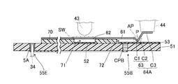
- FIG. 4 is a diagram illustrating a state in which the load detection sensor 5 supports the housing cover 4.
- FIG. 4 is a cross-sectional view of the load detection device 1 on a surface along the front-rear direction of the seat device.
- the load detection sensor 5 is simplified in FIG.
- the front end of the support base 44 has a planar shape, and the height from the lower surface 47LS to the front end of each support base 44 is lower than the height from the lower surface 47LS to the front end of the switch pressing portion 43. That is, the tip of each support base 44 is located above the tip of the switch pressing portion 43.
- the housing cover 4 In a state in which the housing cover 4 covers the housing 3 and the protruding pieces 35 are fitted in the respective openings 42, the tips of the support bases 44 abut against a part of the elastic support portion 64 of the load detection sensor 5.
- the housing cover 4 is supported by the support portion 64.
- the housing cover 4 moves as a whole with respect to the mounting surface 21S so that the angle of the entire upper surface 47US with respect to the mounting surface 21S on which the load detection sensor is mounted changes as described above.
- the load detection sensor 5 moves the housing cover 4 in a state where the entire upper surface 47US moves with respect to the placement surface 21S so that the angle of the entire upper surface 47US with respect to the placement surface 21S on which the load detection sensor is placed changes. It has the elastic support part 64 to support.
- FIG. 5 is an exploded view showing the configuration of the load detection sensor 5.
- 6 is a sectional view taken along line XX of the load detection sensor 5 shown in FIG. 5
- FIG. 7 is a sectional view taken along line YY of the load detection sensor 5 shown in FIG.
- the load detection sensor 5 includes a first electrode sheet 50, a second electrode sheet 60, and a spacer 70 as main components.
- the first electrode sheet 50 includes, for example, an insulating substrate 51 that does not have flexibility.
- Examples of the material of the substrate 51 include phenol resin and epoxy resin.
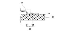
- the first electrode 52 and the first contact portion 53 are disposed on one surface F1 of the substrate 51 that faces the second electrode sheet 60.
- the first electrode 52 is one electrode constituting the switch SW, and is, for example, a circular metal printing layer.
- the first contact portion 53 is formed by connecting a substantially rectangular contact area AR1 that is in contact with the second electrode sheet 60 and a non-contact area AR2 that is not in contact with the second electrode sheet 60 to each other.
- the other surface F2 opposite to the one surface F1 is a lower surface of the load detection sensor 5, and a resistor 54 is disposed on the other surface F2.
- the resistor 54 is a resistor for detecting disconnection.
- the resistor 54 is constituted by a chip resistor.
- the substrate 51 is formed with a plurality of through holes penetrating from one surface F1 to the other surface F2 of the substrate 51.
- the first sheet through hole 55 ⁇ / b> A is a sheet through hole in which an opening is located in a region where the first electrode 52 is disposed on one surface F ⁇ b> 1 of the substrate 51.
- a first conductive member CPA is provided in the first sheet through hole 55A, and the circuit portion and the first electrode 52 arranged on the other surface F2 of the substrate 51 via the first conductive member CPA. Are electrically connected. Thereby, the first conductive member CPA and the resistor 54 are electrically connected, and as a result, the first electrode 52 and the resistor 54 are electrically connected.
- the first conductive member CPA is provided on the inner peripheral surface of the first sheet through hole 55A, and an air hole SP surrounded by the first conductive member CPA is provided in the first sheet through hole 55A. It is formed.
- the second sheet through hole 55B is a sheet through hole in which an opening is located in a region where the first contact portion 53 is disposed on one surface F1 of the substrate 51.
- the opening of the second sheet through hole 55B is positioned in the non-contact area AR2 of the first contact portion 53.
- the second conductive member CPB is filled in the second sheet through hole 55B. Via this second conductive member CPB, the circuit part disposed on the other surface F2 of the substrate 51 and the non-contact area AR2 of the first contact portion 53 are electrically connected, and the other surface F2 of the substrate 51 is connected. , The second conductive member CPB is connected to the resistor 54. Therefore, the resistor 54 and the first contact portion 53 are electrically connected. Since the first electrode 52 and the resistor 54 are electrically connected as described above, the first electrode 52, the resistor 54, and the first contact portion 53 are electrically connected in series in this order.
- the fixing through holes 55 ⁇ / b> C and 55 ⁇ / b> D are through holes through which a pair of fixing pins 33 provided on the bottom wall 37 of the sensor housing portion in the housing 3 are inserted.
- the diameters of the fixing through holes 55 ⁇ / b> C and 55 ⁇ / b> D are approximately the same as the outer diameter of the pair of fixing pins 33.
- the pin through holes 55E and 55F are through holes through which a pair of connection pins 34 provided in the housing 3 are inserted.
- a terminal 5A which is one end portion of the electric circuit in the load detection sensor 5, is provided inside the pin through hole 55E, and the other end portion of the electric circuit in the load detection sensor 5 is provided in the pin through hole 55F.
- a terminal 5B is provided. The terminal 5A is electrically connected to the contact point between the first electrode 52 and the resistor 54, and the terminal 5B is electrically connected to the contact point between the resistor 54 and the first contact part 53.
- the terminals 5A and 5B are provided along the inner peripheral surfaces of the corresponding pin through holes 55E and 55F, and the width of the space surrounded by the terminals 5A and 5B is approximately the same as the outer diameter of the connection pin 34. It is said. When the pair of pin through holes 55E and 55F is inserted, the terminal 5A and one connection pin 34 are electrically connected, and the terminal 5B and the other connection pin 34 are electrically connected.
- the second electrode sheet 60 mainly includes a metal plate 61, a second electrode 62, a second contact portion 63, and an elastic support portion 64 (64A to 64C).
- the metal plate 61 is a thin metal plate having flexibility.
- the metal plate 61 has a vertical width shorter than the vertical width of the substrate 51, and is a thin, substantially rectangular parallelepiped having a horizontal width equal to the horizontal width of the substrate 51. It is made into a shape.
- the material of the metal plate 61 is not particularly limited as long as it is a metal, and examples thereof include copper and stainless steel.
- the metal plate 61 is formed with fixing through holes 65C and 65D penetrating from one surface of the metal plate 61 to the other surface.
- the fixing through holes 65 ⁇ / b> C and 65 ⁇ / b> D are through holes through which a pair of fixing pins 33 provided on the bottom wall of the sensor housing portion in the housing 3 are inserted, and are formed in the substrate 51 of the first electrode sheet 50. It has the same shape and size as the holes 55C and 55D. Further, the arrangement positions of the second electrode 62 and the second contact portion 63 with respect to the fixing through holes 65C and 65D, and the first electrode 52 and the first contact portion 53 with respect to the fixing through holes 55C and 55D in the first electrode sheet 50 are provided. When the first electrode sheet 50 and the metal plate 61 are overlapped with each other, the fixing through hole 55C and the fixing through hole 65C overlap each other, and the fixing through hole 55D The fixing through holes 65D overlap each other.
- the second electrode 62 is the other electrode constituting the switch SW.
- the second electrode 62 is a portion facing the first electrode 52 through the spacer 70 in the metal plate 61. That is, a part of the metal plate 61 also serves as the second electrode 62.
- a metal layer made of the same material as or different from that of the metal plate 61 may be disposed as a second electrode 62 at a portion of the metal plate 61 that faces the first electrode 52 via the spacer 70.
- the second contact part 63 is one member constituting the connection maintaining part AP, and is formed as a leaf spring in the present embodiment. That is, the metal plate 61 is provided with a pair of notches 61A and 61B (FIG. 1) extending from one end on the short side to the other end side of the metal plate 61 with a predetermined interval therebetween. A belt-like portion sandwiched between 61A and 61B (FIG. 1) is the second contact portion 63. Further, the second contact portion 63 is bent so that the cross section along the thickness direction of the metal plate 61 is V-shaped.
- the second contact part 63 is moved away from the turning point P, and the spring piece C1 extending inclined from the turning point P located on the first electrode sheet 50 side toward the root side of the second contact part 63. Accordingly, it has a spring piece C2 that is inclined so as to be separated from the spring piece C1 and extends to the distal end side of the second contact portion 63.
- the turning point P is a portion that contacts the first contact portion 53 of the first electrode sheet 50.
- a portion of the metal plate 61 that is different from the portion that is the second electrode 62 is the second contact portion 63.
- the position where the second contact portion 63 is formed is a position that overlaps the contact area AR1 of the first contact portion 53 when the first electrode sheet 50 and the second electrode sheet 60 are overlapped.
- the shape of the leaf spring formed as the second contact portion 63 may be, for example, a trapezoid whose base width is larger than the width of the open end, and various shapes other than a rectangle and a trapezoid are applicable. is there.
- a metal layer made of the same material as or different from the metal plate 61 may be disposed on the first electrode sheet 50 side in the metal plate 61.
- the elastic support portion 64 is a member that supports the housing cover 4 and has elasticity.
- the elastic support portion 64 supports the housing cover 4 at three locations. That is, in the present embodiment, the elastic support portion 64A located on one short side of the metal plate 61, and the virtual straight line LN passing through the longitudinal direction of the elastic support portion 64A on the other short side of the metal plate 61 (see FIG. A pair of elastic support portions 64B and 64C are provided so as to sandwich 1).
- the elastic support portion 64A is a portion that supports one portion of the housing cover 4 and is formed as a leaf spring using the second contact portion 63 as a part. That is, the elastic support portion 64 ⁇ / b> A includes the spring pieces C ⁇ b> 1 and the spring pieces C ⁇ b> 2 in the second contact portion 63, and a placing piece C ⁇ b> 3 extending from the spring pieces C ⁇ b> 2 substantially parallel to the sheet surface of the metal plate 61.
- the placement piece C3 is positioned higher than the sheet surface of the metal plate main body and is a portion on which one of the plurality of support bases 44 provided on the lower surface 47LS of the housing cover 4 is placed.
- the metal plate main body is a portion of the metal plate 61 other than the second contact portion 63 and the elastic support portion 64 (64A to 64C).
- the elastic support portions 64B and 64C are portions that support two locations opposite to the elastic support portion 64A with respect to the metal plate body, and are formed as leaf springs.
- the elastic support portions 64B and 64C include a spring piece C12 that is inclined and extends from the metal plate main body, and a mounting piece C13 that extends from the spring piece C12 to be substantially parallel to the sheet surface of the metal plate 61.
- the placement piece C13 has the same height as the placement piece C3, and is a portion on which one of the plurality of support bases 44 provided on the lower surface 47LS of the housing cover 4 is placed.
- the spacer 70 is a thin insulating member that is sandwiched between the first electrode sheet 50 and the second electrode sheet 60.
- the spacer 70 has substantially the same shape as that obtained by removing the second contact portion 63 from the metal plate 61.
- the material of the spacer 70 include resins such as PET, PBT, and PEN.
- An opening 71 is formed in the spacer 70.
- the opening 71 is between the first electrode 52 disposed on the substrate 51 and the second electrode 62 of the metal plate 61 facing the first electrode 52, and the first electrode 52 and the second electrode 62 in the vertical direction. It is formed at a position overlapping the two electrodes 62.
- the size of the opening 71 is slightly smaller than the size of the first electrode 52.
- a slit-like opening 72 is formed in the spacer 70.
- the opening 72 is between the first contact portion 53 disposed on the substrate 51 and the second contact portion 63 of the metal plate 61 facing the first contact portion 53, and is the first contact in the vertical direction. It is formed at a position overlapping the portion 53 and the second contact portion 63.
- the size of the opening 72 is slightly larger than the size of the leaf spring formed as the second contact portion 63 in the metal plate 61.
- the spacer 70 is formed with fixing through holes 75C and 75D penetrating from one surface of the spacer 70 to the other surface.
- the fixing through holes 75C and 75D are through holes into which the fixing pins 33 provided on the bottom wall of the sensor housing portion in the housing 3 are inserted, and the fixing through holes 55C formed in the substrate 51 of the first electrode sheet 50. , 55D.
- the fixing through hole 55C, the fixing through hole 65C, and the fixing through hole 75C are overlapped with each other, and the fixing through hole 55D is fixed.
- the through hole 65D and the fixing through hole 75C overlap each other.
- the first electrode sheet 50, the second electrode sheet 60, and the spacer 70 are overlapped to constitute the load detection sensor 5.
- the first electrode 52 and the second electrode 62 face each other through the opening 71 to form a switch SW.
- the distance between the first electrode 52 and the second electrode 62 is, for example, 0.1 mm.
- the air hole SP formed in the electrode through hole 52 ⁇ / b> A communicates with the opening 71. Therefore, when the second electrode 62 is bent and contacts the first electrode 52, unnecessary air can be discharged from the air hole SP to the outside of the load detection sensor 5.
- the first sheet through hole 55A is only a hole for electrically connecting the first electrode 52 disposed on the one surface F1 of the substrate 51 and the circuit portion disposed on the other surface F2 side. It also serves as an exhaust hole for discharging the air in the opening 71 to the outside of the load detection sensor 5.
- the second contact portion 63 of the second electrode sheet 60 is formed as a leaf spring, and is plastically deformed with respect to the sheet surface of the metal plate body so as to be always inclined. is there. Therefore, as shown in FIG. 7, the second contact portion 63 passes through the opening 72 formed by the notch of the spacer 70 and is connected to the contact area AR ⁇ b> 1 of the first contact portion 53 of the first electrode sheet 50.
- the connection maintaining part AP is formed by the first contact part 53 and the second contact part 63 coming into contact with each other.
- the first contact portion 53 of the first electrode sheet 50 is one member constituting the connection maintaining portion AP that maintains the electrical connection even when no external pressure is applied to the housing cover 4 of the load detection sensor unit SU.
- the second contact portion 63 of the second electrode sheet 60 is the other member constituting the connection maintaining portion AP.
- the elastic support portion 64 of the second electrode sheet 60 is formed as a leaf spring, and is always inclined to the side opposite to the side where the second contact portion 63 is inclined with respect to the metal plate main body. It is in. For this reason, as shown in FIG. 4, when the load detection sensor 5 is arranged in the housing space CA of the housing 3 and the housing cover 4 is attached to the housing 3, the elastic support portion 64 includes the support bases of the housing cover 4. The housing cover 4 is supported at three locations so as to lift 44. As described above, the housing cover 4 has the entire upper surface 47US so that the angle of the upper surface 47US with respect to the placement surface 21S changes when viewed along the direction of the placement surface 21S on which the load detection sensor 5 is placed.
- the elastic support part 64 supports the housing cover 4 in a state where the entire upper surface 47US moves relative to the placement surface 21S so that the angle of the upper surface 47US with respect to the placement surface 21S changes.
- the pair of fixing pins 33 in the housing 3 are fixed through holes 55 ⁇ / b> C and 55 ⁇ / b> D in the first electrode sheet 50, and fixed through holes 75 ⁇ / b> C and 75 ⁇ / b> D in the spacer 70. And it is fixed to the housing 3 by being inserted through the fixing through holes 65C and 65D of the second electrode sheet 60 in order. At this time, the substrate 51 and the bottom wall 37 of the housing 3 are located between the first electrode 52 and the mounting surface 21 ⁇ / b> S of the base 2. Further, in a state where the load detection sensor 5 is fixed to the housing 3 and the housing 3 is placed on the pedestal 2, the first electrode 52 and the second electrode 62 are respectively S springs 100 to which the pedestal 2 is locked. It is located below the lower end of.
- the pair of connection pins 34 are inserted into the pin through holes 55E and 55F of the first electrode sheet 50, respectively.
- the terminals 5A and 5B provided in the pin through holes 55E and 55F come into contact with the corresponding connection pins 34 and are electrically connected to the connector terminals of the connector portion 31 of the housing 3 via the connection pins 34.
- the support base 44 of the housing cover 4 contacts the elastic support part 64 of the load detection sensor 5 by attaching the housing cover 4.
- the elastic support portion 64 supports the housing cover 4 in a state where the entire upper surface 47US moves relative to the mounting surface 21S so that the angle of the upper surface 47US with respect to the mounting surface 21S changes.
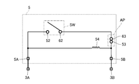
- FIG. 8 is a diagram showing an equivalent circuit of the load detection sensor 5 fixed to the housing 3.
- a switch SW first electrode 52 and second electrode 62
- a connection maintaining unit AP first contact point
- the switch SW is electrically connected between the pair of terminals 5A and 5B, and is connected to connector terminals 3A and 3B provided on the connector portion 31 of the housing 3 via the pair of terminals 5A and 5B. Since the resistor 54 is electrically connected to the first electrode 52 and the first contact portion 53 as described above, the resistor 54 is electrically connected to the switch SW in parallel. Therefore, when the switch SW is turned on, the resistance value between the terminals 5A and 5B is lower than when the switch SW is turned off.
- the lower surface of the seat cushion SC moves downward due to the load of the person.
- the lower surface of the seat cushion SC may be inclined with respect to the S spring surfaces including the respective S springs 100 due to human load.
- the lower surface of the seat cushion SC contacts the upper ends of the pair of hook portions 22. Therefore, even if the lower surface of the seat cushion SC is inclined with respect to the S spring surface as described above, the upper ends of the pair of hook portions 22 press the lower surface of the seat cushion SC, so The slope is relaxed to some extent.
- the lower surface of the seat cushion SC moves downward, the lower surface of the seat cushion SC comes into contact with the upper surface 47US of the housing cover 4 while being deformed by being pressed by the upper ends of the pair of hook portions 22.
- the lower surface of the seat cushion SC may be inclined to some extent while the inclination is relaxed as described above.
- the lower surface of the seat cushion SC is also inclined with respect to the mounting surface 21S of the base 2 locked to the S spring 100, and the housing of the load detection sensor unit SU fixed on the mounting surface 21S.
- the lower surface of the seat cushion SC is also inclined with respect to the upper surface 47US of the cover 4.
- the housing cover 4 can follow the seat cushion SC. It moves so that the angle with respect to the mounting surface 21S changes. Therefore, the upper surface 47US of the housing cover 4 can come into surface contact with the lower surface of the seat cushion SC.
- the gap GA is formed between the housing cover 4 and the housing 3. For this reason, when the lower surface of the seat cushion SC further moves downward, the elastic support portions 64 (64A to 64C) of the load detection sensor 5 supporting the housing cover 4 are bent downward, and the housing cover 4 has the gap GA. Move downward within range.
- FIG. 9 is a diagram illustrating an ON state of the load detection sensor 5. Due to the downward movement of the housing cover 4, the tip of the switch pressing portion 43 presses the second electrode 62, and as shown in FIG. 9, the second electrode 62 contacts the first electrode 52 and the load detection sensor 5. The switch SW is turned on. For this reason, the resistance value between the pair of terminals 5A and 5B becomes low, and the change in resistance is detected by the vehicle control unit (not shown) via the connector terminals 3A and 3B. Thus, the load applied according to the seating is detected.
- the load detection device 1 has the load detection sensor 5 and the upper surface 47US that is a pressure receiving surface that receives pressure from the seat cushion SC of the seat device, and the upper surface 47US corresponds to the seat cushion SC.
- a housing cover 4 as a pressing member that presses the load detection sensor 5 when pressed, and an elastic support portion 64 that supports the housing cover 4 from the load detection sensor 5 side are provided.
- the movement when the housing cover 4 presses the load detection sensor 5 in accordance with the press from the seat cushion SC is alleviated. Accordingly, even if the housing cover 4 may come into contact with another member according to the movement of the housing cover 4, the impact of the housing cover 4 on the other member is reduced, and as a result, abnormal noise can be suppressed.
- the load detection device 1 of the present embodiment can appropriately detect the load while suppressing the generation of abnormal noise.
- the angle of the upper surface 47US of the housing cover 4 that is a pressure receiving surface pressed against the seat cushion SC with respect to the mounting surface 21S of the base 2 changes. For this reason, even when the degree of inclination of the lower surface of the seat cushion SC changes and descends, the upper surface 47US can follow the inclination. Accordingly, the upper surface 47US is pressed in appropriate surface contact with the lower surface of the seat cushion SC. Therefore, according to the load detection apparatus 1 of this embodiment, a load can be detected appropriately.
- the load detection sensor 5 includes the first electrode sheet 50 including at least one or more first electrodes 52, and the housing cover 4 (switch pressing portion 43) than the first electrode sheet 50. ) Side, the second electrode sheet 60 including the second electrode 62 facing the first electrode 52, and the first electrode sheet 50 and the second electrode sheet 60, and at least the first electrode 52 and And a spacer 70 provided with an opening 71 between the second electrodes 62. A part of the second electrode sheet 60 is an elastic support part 64.
- the load detection device 1 can be reduced in size and space.
- the second electrode sheet 60 includes a metal plate 61 on the housing cover 4 (switch pressing portion 43) side, and a part of the metal plate 61 serves as an elastic support portion 64. ing.
- the second electrode sheet 60 includes the metal plate 61 on the housing cover 4 (switch pressing portion 43) side, so that the flexibility does not easily change even when the temperature changes. Therefore, even when the environmental temperature around the load detection device 1 changes, the bending method of the metal plate 61 pressed by the switch pressing portion 43 is not so likely to change. In addition, since a part of the metal plate 61 is the elastic support portion 64, even when the environmental temperature around the load detection device 1 changes, the elastic force of the elastic support portion 64 hardly changes. Therefore, according to this load detection apparatus 1, even if the environmental temperature changes, erroneous detection such as seating can be suppressed.
- the second electrode sheet 60 of the load detection sensor 5 is made of a metal plate 61.
- a portion of the metal plate 61 that faces the first electrode 52 through the opening 71 of the spacer 70 is a second electrode 62, and another portion of the metal plate 61 is an elastic support portion 64.
- the metal plate 61 plays a role as an electrode constituting one of the switches SW and a role as a support portion for supporting the housing cover 4. Therefore, the load detection device 1 according to the present embodiment can appropriately detect the load while suppressing the generation of abnormal noise while suppressing the number of parts of the load detection sensor 5.
- connection maintaining unit AP is configured that maintains electrical connection even when external pressure is not applied between a part of the first electrode sheet 50 and a part of the second electrode sheet 60. Is done.
- the circuit formed on the first electrode sheet 50 and the circuit formed on the second electrode sheet 60 are always in a conductive state via the connection maintaining part AP. Therefore, even when the series number of switches SW connected in series in the circuit in the load detection sensor 5 is an odd number, in the load detection sensor 5, the pair of terminals 5 ⁇ / b> A and 5 ⁇ / b> B of the circuit are arranged only in the first electrode sheet 50. be able to.
- a part of the metal plate 61 constituting the connection maintaining part AP also serves as the elastic support part 64A.
- a force acts on the elastic support portion 64A as a repulsive force on the first electrode sheet 50 side, and a force acts on a part of the second electrode sheet 60 constituting the connection maintaining portion AP on the first electrode sheet 50 side. . Therefore, the connection state of the connection maintaining unit AP can be made stronger.
- the metal plate 61 plays a role of arranging the pair of terminals 5 ⁇ / b> A and 5 ⁇ / b> B on the first electrode sheet 50 and a role as a support portion for supporting the housing cover 4. For this reason, it is possible to appropriately detect the load while suppressing the generation of abnormal noise while further suppressing the number of parts of the load detection sensor 5.
- the portion where the elastic support portion 64 supports the housing cover 4 is located above the load detection sensor 5. For this reason, it becomes possible to achieve size reduction as compared with the case where the elastic support portion supports the pressing member below the load detection sensor 5.
- the 2nd electrode sheet 60 consists of the metal plate 61 as mentioned above. For this reason, since there is little influence by the heat in the 2nd electrode sheet 60, even if it uses in high temperature environment or a low temperature environment, the sensitivity of the load detection sensor 5 is stabilized. Moreover, since the 2nd electrode sheet 60 is a metal, damage etc. can be reduced and durability can be improved. Furthermore, since the second contact portion 63 that is a leaf spring in the second electrode sheet 60 is also a metal, the second contact formed as the leaf spring is compared with a case where a part of the resin sheet is a leaf spring. The malleability and ductility of the part 63 can be increased. Accordingly, it is possible to reduce breakage such as breakage of the second contact portion 63 formed as a leaf spring and improve the durability of the leaf spring.
- the substrate 51 serving as the sheet of the first electrode sheet 50 penetrates from one surface F1 facing the second electrode sheet 60 to the other surface F2. It has a through hole 55A. Further, the first electrode 52 is electrically connected to a circuit portion disposed on the other surface F2 of the substrate 51 through a first conductive member CPA provided in the first sheet through hole 55A. For this reason, it becomes possible to take out one terminal 5A to the other surface F2 of the board
- circuit part can be provided on the other surface F2, it is not necessary to provide the circuit part on the one surface F1, and unevenness due to the circuit part on the one surface F1 can be reduced. Thereby, the sensitivity of the load detection sensor 5 can be stabilized.
- the opening on the one surface side of the first sheet through hole 55A is located in the region where the first electrode 52 is disposed on the one surface F1 of the substrate 51.
- the first sheet through hole 55 ⁇ / b> A has an air hole SP that communicates with the opening 71 between the first electrode 52 and the second electrode 62 via the electrode through hole 52 ⁇ / b> A provided in the first electrode 52.
- the first sheet through-hole 55 ⁇ / b> A is a connection hole for electrically connecting the first electrode 52 disposed on the one surface F ⁇ b> 1 of the substrate 51 to the circuit portion on the other surface side of the substrate 51.
- it also serves as an exhaust hole for discharging the spacer air to the outside. For this reason, durability of the board
- substrate 51 can be improved compared with the case where a connection hole and an exhaust hole are provided separately. Further, it is not necessary to provide a separate exhaust hole, and space can be saved.
- the substrate 51 serving as the sheet of the first electrode sheet 50 is located at a position different from the first sheet through-hole 55A from one surface F1 facing the second electrode sheet 60. It has the 2nd sheet penetration hole 55B which penetrates to the other field F2. Further, the first contact portion 53 is electrically connected to a circuit portion disposed on the other surface F2 of the substrate 51 through a second conductive member CPB provided in the second sheet through hole 55B. For this reason, the pair of terminals 5A and 5B can be taken out from the other surface F2 of the substrate 51. As in the present embodiment, the terminals 5A and 5B can be arranged inside the pin through holes 55E and 55F different from the first sheet through hole 55A.
- the circuit part can be provided on the other surface F2, it is not necessary to provide the circuit part on the one surface F1, and unevenness due to the circuit part on the one surface F1 can be reduced. Thereby, the sensitivity of the load detection sensor 5 can be stabilized.
- the load detection sensor 5 of the present embodiment has a resistor 54 that is disposed on the other surface F2 of the substrate 51 and connects the first electrode 52 and the first contact portion 53. For this reason, even if the thickness of the resistor 54 is large, it can be avoided that the sensitivity of the load detection device 1 is deteriorated due to the thickness.
- the circuit portion and the resistor 54 in the first electrode sheet 50 are provided on the other surface F2 of the substrate 51, and the pair of terminals 5A and 5B are provided in the pin through holes 55E and 55F. .
- components other than the 1st electrode 52 and the 1st contact part 53 can be excluded from one surface F1 of the board
- FIG. Therefore, the unevenness
- the metal plate 61 of the second electrode sheet 60 constituting the load detection sensor 5 is different from the load detection device 1 in the first embodiment. That is, the metal plate 61 in the first embodiment employs elastic support portions 64A to 64C that support the housing cover 4 at three locations. On the other hand, in this embodiment, the elastic support part which supports the housing cover 4 in two places is employ
- FIG. 10 is a view and a cross-sectional view of the metal plate 61 of the load detection sensor according to the second embodiment as viewed from the upper surface side.
- the load detection sensor of the present embodiment supports the housing cover 4 by a pair of elastic support portions 64B and 64C that are different in arrangement position from the first embodiment.
- the elastic support portion 64B of the present embodiment is disposed so as to extend from an intermediate portion on one long side of the metal plate 61. Further, the elastic support portion 64 ⁇ / b> C is disposed so as to extend from an intermediate portion on the other long side of the metal plate 61.
- the elastic support portion 64A of the first embodiment formed by using the second contact portion 63 as a part is omitted, and the shape of the second contact portion 63 of the present embodiment is changed.
- the second contact portion 63 of the present embodiment includes a spring piece C ⁇ b> 1 and a spring piece C ⁇ b> 1 extending substantially parallel to the sheet surface of the metal plate 61. It consists of a contact piece C4.
- the contact piece C ⁇ b> 4 is a portion that contacts the first contact portion 53 of the first electrode sheet 50.
- the number and arrangement positions of the support bases 44 of the housing cover 4 are changed.
- the number of the support bases 44 in this embodiment is two, and is provided at a position corresponding to the pair of elastic support portions 64B and 64C.
- the support base 44 is arranged so as to come into contact with the mounting pieces C13 of the pair of elastic support portions 64B and 64C in the load detection sensor 5. Is done.
- the movement of the upper surface 47US, which is the pressure receiving surface of the housing cover 4, following the inclination of the bottom surface of the seat cushion SC is alleviated. Therefore, even if the housing cover 4 may come into contact with another member such as the frame wall 38 of the housing 3 according to the movement of the housing cover 4, the impact of the housing cover 4 on the other member is reduced. Can be suppressed.
- the metal plate 61 of the second electrode sheet 60 constituting the load detection sensor 5 is different from the load detection device 1 in the first embodiment. That is, in the metal plate 61 in the first embodiment, the elastic support portion 64 that supports the housing cover 4 at three locations is employed. On the other hand, in this embodiment, the elastic support part which supports the housing cover 4 in two places is employ
- FIG. 12 is a diagram showing a cross section of the metal plate 61 of the load detection sensor according to the second embodiment as viewed from the upper surface side.
- the load detection sensor of the present embodiment supports the housing cover 4 by a pair of elastic support portions 64B and 64C that are different from the first embodiment in the arrangement position.
- the elastic support portion 64B of the present embodiment is disposed so as to extend from the end portion on the short side where the second contact portion 63 is provided in the metal plate 61. Further, the elastic support portion 64C is disposed on the other short side of the metal plate 61 so as to extend from an end portion that is diagonally opposite to the elastic support portion 64B.
- the elastic support portion 64A of the first embodiment formed by using the second contact portion 63 as a part is omitted, and the second contact portion 63 of the present embodiment is, for example, a spring piece shown in FIG. C1 and contact piece C4 are comprised.
- the number and arrangement positions of the support bases 44 of the housing cover 4 are changed.
- the number of the support bases 44 in this embodiment is two, and is provided at a position corresponding to the pair of elastic support portions 64B and 64C.
- the support base 44 is arranged so as to come into contact with the mounting pieces C13 of the pair of elastic support portions 64B and 64C in the load detection sensor 5. Is done.
- the movement of the upper surface 47US, which is the pressure receiving surface of the housing cover 4, following the inclination of the bottom surface of the seat cushion SC is alleviated. Therefore, even if the housing cover 4 may come into contact with another member such as the frame wall 38 of the housing 3 according to the movement of the housing cover 4, the impact of the housing cover 4 on the other member is reduced. Can be suppressed.
- the metal plate 61 of the second electrode sheet 60 constituting the load detection sensor 5 is different from the load detection device 1 in the first embodiment. That is, in the metal plate 61 in the first embodiment, the elastic support portion 64 that supports the housing cover 4 at three locations is employed. On the other hand, in this embodiment, the elastic support part 64 which supports the housing cover 4 in one place is employ
- FIG. 13 is a diagram showing the load detection device in the fourth embodiment from the same viewpoint as FIG. 4, and FIG. 14 is a diagram showing the load detection device in the fourth embodiment from the same viewpoint as in FIG.
- the pair of elastic support portions 64B and 64C is omitted, and only the elastic support portion 64A is left. Therefore, as shown in FIG. 14, the switch pressing portion 43 is used as a reference and formed between the top wall 47 of the housing cover 4 and the frame wall 38 of the housing 3 on the side opposite to the elastic support portion 64 ⁇ / b> A side.
- the gap GA disappears, the top wall 47 and the frame wall 38 come into contact with each other, and a part of the housing cover 4 is supported by the frame wall 38.
- the movement of the upper surface 47US, which is the pressure receiving surface of the housing cover 4, following the inclination of the bottom surface of the seat cushion SC is alleviated. Therefore, even if the housing cover 4 may come into contact with another member such as the frame wall 38 of the housing 3 according to the movement of the housing cover 4, the impact of the housing cover 4 on the other member is reduced. Can be suppressed.
- the entire housing cover 4 is supported, It is preferable that the top wall 47 of the housing cover 4 and the frame wall 38 of the housing 3 are not in contact with each other.
- FIG. 15 is a diagram showing the load detection device in the fifth embodiment from the same viewpoint as in FIG. 2, and FIG. 16 is a diagram showing the configuration of the load detection sensor 5 in the fifth embodiment from the same viewpoint as in FIG. .
- the load detection sensor unit SU is configured by the housing 3, the housing cover 4, the load detection sensor 5, and the plate-like member 67 made of metal as an elastic support portion, and the load detection sensor unit SU
- the pedestal 2 constitutes the load detection device 1.
- the slit-shaped opening 72 is omitted, and a slit SR for air removal is provided.
- the 1st electrode sheet 50 in this embodiment it replaces with the board
- the insulating sheet 56 includes a sheet main body 56A and a terminal arrangement portion 56B protruding from the sheet main body.
- a plate-like terminal 5A is arranged on the same surface as the surface on which the first electrode 52 is provided in the sheet main body 56A.
- the terminal 5A is connected to the first electrode 52 via a wire and electrically connected to the connector terminal of the connector portion 31 via a lead wire or the like.
- the connection pins 34 are also omitted as with the fixing pins 33.
- resin such as PET, PBT, or PEN, is mentioned.
- the first contact portion 53, the first sheet through hole 55A, the second sheet through hole 55B, the fixing through holes 55C and 55D, and the pin through holes 55E and 55F are omitted.
- the insulating sheet 66 includes a sheet main body 66A and a terminal arrangement portion 66B protruding from the sheet main body.
- the terminal arrangement portion 66B is provided so as not to overlap with the terminal arrangement portion 56B in a direction orthogonal to the sheet surface, and the terminal arrangement portion 66B has a surface on which the second electrode 62 is provided in the sheet main body 66A.
- a plate-like terminal 5B is disposed on the same surface.
- the terminal 5B is connected to the second electrode 62 via a wire and electrically connected to the connector terminal of the connector portion 31 via a lead wire or the like.
- resin such as PET, PBT, or PEN, is mentioned.
- the second contact part 63 and the fixing through holes 65C and 65D are omitted.
- the load detection sensor 5 of the present embodiment does not have the connection maintaining unit AP and has a so-called membrane switch configuration.
- the elastic support part 64 formed in a part of the said metal plate 61 is lose
- a plate-like member 67 made of metal as an elastic support portion is newly provided. That is, in the present embodiment, a plate-like member 67 as an elastic support portion is provided separately from the load detection sensor 5.
- the plate-like member 67 is not fixed to the insulating sheet 66 but is fixed to the housing 3. As shown in FIG. 15, in the present embodiment, a pair of ribs 39 are provided at positions surrounded by the frame wall 38. The distance between the ribs 39 is smaller than the length of the plate member 67, and both ends of the plate member 67 are fixed to these ribs 39. Thereby, the plate-shaped member 67 is curved in an arch shape toward the housing cover 4 side which is a pressing member. The plate-like member 67 is larger than the pair of insulating sheets 56 and 66.
- a through hole 68 through which the switch pressing portion 43 is inserted is provided at a portion including a position where the bending rate is highest in the plate member 67.
- the switch pressing portion 43 passes through the through hole 68 of the plate member 67, and the tip of the switch pressing portion 43 is positioned between the plate member 67 and the insulating sheet 66.
- the plate-like member 67 supports the housing cover 4 in a state where the entire upper surface 47US moves with respect to the mounting surface 21S so that the angle of the upper surface 47US with respect to the mounting surface 21S changes. That is, the entire plate-like member 67 is an elastic support portion.
- the movement of the upper surface 47US, which is the pressure receiving surface of the housing cover 4, following the inclination of the bottom surface of the seat cushion SC is alleviated. Therefore, even if the housing cover 4 may come into contact with another member such as the frame wall 38 of the housing 3 according to the movement of the housing cover 4, the impact of the housing cover 4 on the other member is reduced. Can be suppressed.
- the plate-like member 67 of the present embodiment is provided between the load detection sensor 5 and the housing cover 4 (switch pressing portion 43) as a pressing member, and is made of metal.
- the plate member 67 is curved in an arch shape toward the housing cover 4 side, and the entire plate member 67 is an elastic support portion.
- the housing cover 4 that presses the load detection sensor 5 by being pressed by the seat cushion SC is supported by a plate-like member 67 that curves in an arch shape toward the housing cover 4 side.
- the change in the load applied from the housing cover 4 to the load detection sensor 5 is likely to depend on the plate-like member 67 that supports the housing cover 4.
- the plate-like member 67 is made of metal, it is difficult to reduce deterioration as compared with the case of being made of resin or the like. Therefore, even if the housing cover 4 is continuously pressed from the seat cushion SC for a long period of time, the change in the load applied to the load detection sensor 5 from the housing cover 4 by the plate member 67 can be reduced. As a result, the load can be detected appropriately.
- the plate-like member 67 supports the housing cover 4 as a whole, it is easier to support the housing cover 4 more stably than when the housing cover 4 is supported by a part of the plate-like member 67. it can.
- the material of the plate-like member 67 is made of metal, but is preferably made of bimetal that is deformed so as to be separated from the insulating sheet 66 as the temperature rises.
- the electrode is formed on the resin insulating sheet 66 as in this embodiment, the insulating sheet 66 is likely to be deformed as the temperature rises, and the switch SW is easily turned on with a weak force as the temperature rises. Become. Metals do not change flexibility even when the temperature changes, but the flexibility does not change at all.
- the plate-like member 67 is formed of a bimetal that is deformed so as to be separated from the insulating sheet 66 as the temperature rises, so that when the temperature rises, the insulating sheet 66 can be easily bent or the switch SW with a weak force. It is possible to prevent the load detection from changing due to the fact that the plate-like member 67 is separated from the insulating sheet 66. Therefore, the load can be detected more appropriately.
- the upper surface 47US is configured to move relative to the mounting surface 21S so that the angle of the upper surface 47US that is the pressure receiving surface with respect to the mounting surface 21S changes in the front-rear direction and the left-right direction of the seat device.
- the present invention is not limited to this.
- the pressure receiving surface may move relative to the mounting surface 21S so that the angle of the pressure receiving surface with respect to the mounting surface 21S changes only in the front-rear direction.
- the load detection sensor 5 may have an axis extending in the left-right direction of the seat device, and the pressure receiving surface may move only in the front-rear direction around the axis.
- the load detection sensor unit SU may have an axis extending in the front-rear direction of the seat device, and the pressure receiving surface may move only in the left-right direction around the axis.
- the pressure receiving surface may move so that the angle of the load detection sensor 5 with respect to the placement surface 21S does not change and moves up and down with respect to the placement surface 21S.
- the upper surface 47US may move with respect to the placement surface 21S so that the angle of the upper surface 47US with respect to the placement surface 21S changes equally in the front-rear direction and the left-right direction of the seat device.
- the upper surface 47US which is a pressure receiving surface, may move so as to move up and down with respect to the mounting surface 21S described above without changing the angle of the load detection sensor 5 with respect to the mounting surface 21S.
- the pressing member that presses the load detection sensor 5 is the housing cover 4.
- the housing cover 4 may be omitted, and a pressing member may be disposed on the load detection sensor 5.
- the pressing member has a pressure receiving surface that receives pressure from the seat cushion of the seat device and presses the load detection sensor 5 by pressing the pressure receiving surface, members having various configurations can be adopted. is there.
- the housing 3 is provided, but the housing 3 may be omitted. In this case, the load detection sensor 5 is directly provided on the base 2, and the housing cover 4 is locked to the base 2.
- the portion where the elastic support portion 64 supports the housing cover 4 is located above the load detection sensor 5.
- the portion of the elastic support portion 64 that supports the housing cover 4 may be changed to the load detection sensor 5 or less by changing the shape of the housing cover 4 or the like.
- the elastic support portion 64 supports the housing cover 4 in a state where the switch pressing portion 43 of the housing cover 4 and the metal plate 61 of the load detection sensor 5 are separated from each other.
- the elastic support portion 64 may support the housing cover 4 with the switch pressing portion 43 in contact with the metal plate 61.
- the said embodiment is set as the structure which the front-end
- the member that presses the switch SW and the shaft portion having the tip serving as the rotation center of the upper surface 47US may be configured separately.
- the 1st electrode 52 and the 2nd electrode 62 shall be located below each S spring 100 with which the base 2 is latched.
- the first electrode 52 and the second electrode 62 are S. It does not have to be positioned below the spring 100.
- the first electrode 52 and the second electrode 62 may be positioned between the lower end portion and the upper end portion of the S spring 100.
- the placement surface 21S on which the load detection sensor 5 is placed is positioned below the respective S springs 100 to which the base 2 is locked.
- the placement surface 21S may be higher than the lower end portion of the S spring 100 and lower than the upper end portion.
- the mounting surface. 21S is preferably positioned below the lower end of each S spring 100 to which the base 2 is locked or at the same height as the lower end of the S spring 100.
- the load detection sensor 5 is not specifically limited as long as it has a pair of electrodes.
- the load detection sensor 5 of the first embodiment to the fourth embodiment may be the load detection sensor 5 of the fifth embodiment, and the load detection sensor 5 of the fifth embodiment is the first embodiment to the fourth embodiment.
- the load detection sensor 5 may be used.
- a load detection sensor other than the load detection sensor 5 of the first to fifth embodiments may be employed.
- the load detection sensor 5 of the fifth embodiment is applied in place of the load detection sensor 5 of the first to fourth embodiments.
- the metal plate is arrange
- a two-electrode sheet is configured, and a part of the second electrode sheet is an elastic support portion.
- the 2nd electrode sheet contains the insulating sheet 66 and the metal plate arrange
- the load detection sensor unit SU may be arranged on the seat pan of the seat device by removing the base 2 and changing the shape of the housing 3.
- the load detection device of the present invention has applicability as long as it detects the presence or absence of a load on a detection target to be detected. That is, in the above-described embodiment, the load detection device is disposed below the seat cushion SC of the vehicle, and the load applied according to the seating of the person is detected. For example, the form which arrange
Abstract
A load detection device (1) is provided with: a load detection sensor (5); a housing cover (4) as a pressing member, which has an upper surface (47US) as a pressure receiving surface for receiving pressure from a seat cushion (SC), and which presses the load detection sensor (5) when the upper surface (47US) is pressed by the seat cushion (SC); and an elastic supporting section (64) that supports the housing cover (4) from the load detection sensor (5) side.
Description
本発明は、荷重検知装置に関し、着座等に応じて加わる荷重を検知する場合に好適なものである。
The present invention relates to a load detection device and is suitable for detecting a load applied according to seating or the like.
車両における安全システムの一つとして、乗車時にシートベルトが非着用であることを警告するアラームシステムが実用化されている。このアラームシステムでは、人の着座が感知されている状態でシートベルトの着用が非感知となる場合に、警告が発せられる。この人の着座を感知する装置として、着座に応じて加わる荷重を検知する荷重検知装置が用いられる場合がある。
As one of the safety systems in vehicles, an alarm system that warns that a seat belt is not worn when riding is put into practical use. In this alarm system, a warning is issued when the seat belt is not detected while a person is seated. As a device for detecting the seating of the person, a load detection device that detects a load applied in accordance with the seating may be used.
このような荷重検知装置として、座席のシートクッション下に配置されるものがある。座席には、シートクッションがシートパン上に配置される場合と、シートクッションがフレームに固定される複数のSばねに上に配置される場合とがある。シートクッションが複数のSばねに上に配置される座席においては、荷重検知装置がSばねに係止されて使用される場合がある。下記特許文献1には、このような荷重検知装置が記載されている。特許文献1に記載の荷重検知装置は、Sばねに係止される台座と、台座上にスペーサを介して配置されるメンブレンスイッチとを有する。
Some of such load detection devices are arranged under the seat cushion of the seat. In the seat, there are a case where the seat cushion is arranged on the seat pan and a case where the seat cushion is arranged on a plurality of S springs fixed to the frame. In a seat in which a seat cushion is disposed on a plurality of S springs, the load detection device may be used while being locked to the S springs. Patent Document 1 listed below describes such a load detection device. The load detection device described in Patent Literature 1 includes a pedestal that is locked to an S spring, and a membrane switch that is disposed on the pedestal via a spacer.
ところで、一般的にシートクッションの下に配置される荷重検知装置においては、座席に人が着座することでシートクッションを介して荷重検知装置に荷重が加わる。このため、上記特許文献1では、荷重検知装置に加わる荷重は弱くなり、着座に応じて加わる荷重を適切に検知できなくなる懸念がある。
Incidentally, in a load detection device that is generally disposed under a seat cushion, a load is applied to the load detection device via the seat cushion when a person sits on the seat. For this reason, in the said patent document 1, the load added to a load detection apparatus becomes weak, and there exists a possibility that the load added according to seating cannot be detected appropriately.
そこで、例えば次のような構成が考えられる。すなわち、座席のシートクッションからの押圧を受ける受圧面が押圧されることで荷重検知センサをオンする押圧部材をスイッチに設けることが考えられる。
Therefore, for example, the following configuration can be considered. That is, it is conceivable to provide the switch with a pressing member that turns on the load detection sensor when the pressure receiving surface that receives the pressure from the seat cushion of the seat is pressed.
しかしながら、上記のような構成を考えた場合、押圧部材が動く分だけ不安定になるため、当該押圧部材の動きに応じて他の部材と接触して異音が発生することが懸念される。
However, considering the above-described configuration, the pressure member becomes unstable due to the movement of the pressing member, and there is a concern that abnormal noise may occur due to contact with other members according to the movement of the pressing member.
そこで、本発明は、異音の発生を抑えつつも荷重を適切に検知することができる荷重検知装置を提供することを目的とする。
Therefore, an object of the present invention is to provide a load detection device that can appropriately detect a load while suppressing the occurrence of abnormal noise.
上記課題を解決するため本発明の荷重検知装置は、荷重検知センサと、シートクッションからの押圧を受ける受圧面を有し、前記受圧面が前記シートクッションに押圧されることで前記荷重検知センサを押圧する押圧部材と、前記押圧部材を前記荷重検知センサ側から支持する弾性支持部とを備えることを特徴とする。
In order to solve the above problems, a load detection device according to the present invention has a load detection sensor and a pressure receiving surface that receives pressure from a seat cushion, and the load detection sensor is configured by pressing the pressure receiving surface against the seat cushion. A pressing member for pressing and an elastic support portion for supporting the pressing member from the load detection sensor side are provided.
このような荷重検知装置では、例えば、座席やベッド等のシートクッションの下面に押圧部材の受圧面が対向され、当該押圧部材に押圧される荷重検知センサと、当該押圧部材を荷重検知センサ側から支持する弾性支持部とが設けられる。
押圧部材は弾性支持部によって荷重検知センサ側から支持されているため、当該荷重検知センサに荷重が加わっていない時に、押圧部材が動いて他の部材と接触し、その接触に起因する異音の発生を防止することができる。
また、シートクッションからの押圧に応じて押圧部材が荷重検知センサを押圧するときの動きも緩和される。したがって、押圧部材の動きに応じて他の部材と接触する場合があっても、当該他の部材に対する押圧部材の衝撃が低減され、この結果、異音を抑えることができる。
こうして、荷重検知装置は、異音の発生を抑えつつも荷重を適切に検知することができる。 In such a load detection device, for example, a pressure detection surface of the pressing member is opposed to the lower surface of a seat cushion such as a seat or a bed, and the pressure detection member is pressed from the pressing member. And an elastic support part to support.
Since the pressing member is supported from the load detection sensor side by the elastic support portion, when the load is not applied to the load detection sensor, the pressing member moves and contacts other members, and abnormal noise caused by the contact is generated. Occurrence can be prevented.
Further, the movement when the pressing member presses the load detection sensor in response to the pressing from the seat cushion is also alleviated. Therefore, even if it may contact with another member according to a motion of a press member, the impact of the press member with respect to the other member is reduced, and as a result, abnormal noise can be suppressed.
In this way, the load detection device can appropriately detect the load while suppressing the occurrence of abnormal noise.
なお、前記受圧面は、前記荷重検知センサが載置される載置面に対する角度が変化するように、前記載置面に対して動くことが好ましい。
In addition, it is preferable that the said pressure receiving surface moves with respect to the said mounting surface so that the angle with respect to the mounting surface in which the said load detection sensor is mounted changes.
このようにした場合、シートクッションの下面が傾斜する場合であっても、当該傾斜に受圧面が追随することができる。従って、受圧面はシートクッションの下面に適切に押圧され、荷重を適切に検知することができる。
In this case, even if the lower surface of the seat cushion is inclined, the pressure receiving surface can follow the inclination. Therefore, the pressure receiving surface is appropriately pressed against the lower surface of the seat cushion, and the load can be detected appropriately.
また、前記荷重検知センサは、少なくとも1以上の第1電極を含む第1電極シートと、前記第1電極シートよりも前記押圧部材側に配置され、前記第1電極に対向される第2電極を含む第2電極シートと、前記第1電極シート及び前記第2電極シートの間に配置され、少なくとも前記第1電極及び前記第2電極の間に開口が設けられるスペーサとを有し、前記第2電極シートの一部が前記弾性支持部とされることが好ましい。
The load detection sensor includes: a first electrode sheet including at least one first electrode; and a second electrode that is disposed closer to the pressing member than the first electrode sheet and faces the first electrode. A second electrode sheet, and a spacer disposed between the first electrode sheet and the second electrode sheet, and having an opening provided at least between the first electrode and the second electrode. It is preferable that a part of the electrode sheet is the elastic support portion.
このようにした場合、荷重検知装置において荷重検知センサとは別に弾性支持部材を設ける必要がないため、当該荷重検知装置の小型化、省スペース化が可能となる。
In this case, since it is not necessary to provide an elastic support member separately from the load detection sensor in the load detection device, it is possible to reduce the size and space of the load detection device.
また、前記第2電極シートは、前記押圧部材側に金属板を含み、前記金属板の一部が前記弾性支持部とされることが好ましい。
Moreover, it is preferable that the second electrode sheet includes a metal plate on the pressing member side, and a part of the metal plate is used as the elastic support portion.
このようにした場合、第2電極シートは、押圧部材側に金属板を含むので、温度が変化する場合においても可撓性が変化しづらい。従って、荷重検知装置の周りの環境温度が変化する場合であっても、押圧部材で押圧される金属板の撓み方は然程変化しづらい。また、金属板の一部が弾性支持部であるため、荷重検知装置の周りの環境温度が変化する場合でも、弾性支持部の弾性力は変化しづらい。従って、この荷重検知装置によれば、環境温度が変化する場合であっても、着座等の誤検出を抑制することができる。
In this case, since the second electrode sheet includes a metal plate on the pressing member side, the flexibility does not easily change even when the temperature changes. Therefore, even when the environmental temperature around the load detection device changes, the bending method of the metal plate pressed by the pressing member is hardly changed. Moreover, since a part of metal plate is an elastic support part, even when the environmental temperature around a load detection apparatus changes, the elastic force of an elastic support part does not change easily. Therefore, according to the load detection device, erroneous detection such as seating can be suppressed even when the environmental temperature changes.
また、前記第2電極シートは金属板からなり、前記金属板のうち前記開口を介して前記第1電極に対向する部位が前記第2電極とされ、前記金属板の他の部位が前記弾性支持部とされることが好ましい。
The second electrode sheet is made of a metal plate, and a portion of the metal plate that faces the first electrode through the opening is the second electrode, and the other portion of the metal plate is the elastic support. It is preferable to be a part.
このようにした場合、スイッチの一方を構成する電極としての役割と、押圧部材を支持する支持部としての役割とを金属板が担うことになる。このため、荷重検知センサの部品点数を抑えながら、異音の発生を抑えつつも荷重を適切に検知することができる。
In this case, the metal plate plays a role as an electrode constituting one of the switches and a role as a support portion for supporting the pressing member. For this reason, it is possible to appropriately detect the load while suppressing the generation of abnormal noise while suppressing the number of parts of the load detection sensor.
また、前記第2電極シートは、前記第2電極が設けられる絶縁シートと前記絶縁シートにおける前記押圧部材側の面上に配置される前記金属板を含むことが好ましい。
Further, it is preferable that the second electrode sheet includes an insulating sheet on which the second electrode is provided and the metal plate disposed on a surface of the insulating sheet on the pressing member side.
このようにした場合にも荷重検知装置において荷重検知センサとは別に弾性支持部材を設ける必要がないため、当該荷重検知装置の小型化、省スペース化が可能となる。
Even in this case, since it is not necessary to provide an elastic support member separately from the load detection sensor in the load detection device, the load detection device can be reduced in size and space.
また、前記第1電極シートの一部分と前記第2電極シートの一部分とで外圧が加わらない場合にも電気的な接続が維持される接続維持部が構成され、前記接続維持部を構成する前記第2電極シートの一部分は前記弾性支持部を兼ねることが好ましい。
In addition, a connection maintaining unit that maintains electrical connection even when an external pressure is not applied between a part of the first electrode sheet and a part of the second electrode sheet is configured, and the first component that configures the connection maintaining unit It is preferable that a part of the two-electrode sheet also serves as the elastic support portion.
このようにした場合、荷重検知センサでは、第1電極シートに形成される回路と第2電極シートに形成される回路とが接続維持部を介して常時的に導通状態になる。このため、荷重検知センサにおける回路において直列に接続されるスイッチの直列数が奇数の場合においても、当該荷重検知センサでは回路の一対の端子を第1電極シート及び第2電極シートのいずれか一方だけに配置することができる。
また、接続維持部を構成する第2電極シートの一部分は弾性支持部を兼ねているため、弾性支持部には、反発力として第1電極シート側に力が働き、接続維持部を構成する第2電極シートの一部分にも第1電極シート側に力が働く。このため、接続維持部の接続状態をより強固なものとすることができる。
さらに、一対の端子を一方の電極シートに配置させる役割と、押圧部材を支持する支持部としての役割とを金属板が担うことになる。このため、荷重検知センサの部品点数を抑えながら、異音の発生を抑えつつも荷重を適切に検知することができる。 In this case, in the load detection sensor, the circuit formed on the first electrode sheet and the circuit formed on the second electrode sheet are always in a conductive state via the connection maintaining unit. For this reason, even when the number of switches connected in series in the circuit in the load detection sensor is an odd number, in the load detection sensor, only one of the first electrode sheet and the second electrode sheet is used as the pair of terminals of the circuit. Can be arranged.
In addition, since a part of the second electrode sheet constituting the connection maintaining portion also serves as an elastic support portion, a force acts on the elastic support portion on the first electrode sheet side as a repulsive force, and the connection maintaining portion is configured. A force acts on the first electrode sheet side also in a part of the two-electrode sheet. For this reason, the connection state of a connection maintenance part can be made stronger.
Further, the metal plate plays a role of arranging the pair of terminals on one electrode sheet and a role as a support portion for supporting the pressing member. For this reason, it is possible to appropriately detect the load while suppressing the generation of abnormal noise while suppressing the number of parts of the load detection sensor.
また、前記弾性支持部は、前記荷重検知センサと前記押圧部材の間に設けられる金属からなる板状部材であり、前記板状部材が前記押圧部材側に向かってアーチ状に湾曲され、前記板状部材全体が前記弾性支持部とされることが好ましい。
The elastic support part is a plate-like member made of metal provided between the load detection sensor and the pressing member, and the plate-like member is curved in an arch shape toward the pressing member side, and the plate It is preferable that the entire member is the elastic support portion.
このようにした場合、シートクッションに押圧されることで荷重検知センサを押圧する押圧部材が、その押圧部材側に向かってアーチ状に湾曲する板状部材によって支持される。このため、押圧部材から荷重検知センサに加わる荷重の変化は、当該押圧部材を支持する板状部材に依存し易くなる。また、この板状部材は金属からなるので樹脂等からなる場合に比べると劣化が低減し難い。したがって、シートクッションから長期間にわたって押圧部材が押圧され続けても、板状部材によって、当該押圧部材から荷重検知センサに加わる荷重の変化を低減することができる。この結果、荷重を適切に検知することができる。
In this case, the pressing member that presses the load detection sensor by being pressed by the seat cushion is supported by a plate-like member that curves in an arch shape toward the pressing member side. For this reason, the change in the load applied to the load detection sensor from the pressing member is likely to depend on the plate-like member that supports the pressing member. Further, since this plate-like member is made of metal, it is difficult to reduce deterioration as compared with the case of being made of resin or the like. Therefore, even if the pressing member is continuously pressed from the seat cushion for a long period of time, a change in load applied from the pressing member to the load detection sensor can be reduced by the plate-like member. As a result, the load can be detected appropriately.
また、前記板状部材は、温度の上昇に伴い前記絶縁シートから離れるように変形するバイメタルから形成されていることが好ましい。
Moreover, it is preferable that the plate-like member is formed of a bimetal that is deformed so as to be separated from the insulating sheet as the temperature rises.
絶縁シートは温度の上昇に伴い変形し易くなり、温度の上昇に伴い弱い力で荷重検知センサがオンし易くなる。また、金属は温度が変化する場合においても可撓性が然程変化しないが、全く可橈性が変化しないわけではない。このため、金属板が温度の上昇に伴い絶縁シートから離れるように変形するバイメタルから形成されると、温度が上昇する場合に、絶縁シートが撓み易くなることや弱い力で荷重検知センサがオンし易くなることと、金属板が絶縁シートから離れることとにより、荷重の検知が変化することを抑制することができる。従って、より適切に荷重を検知することができる。
The insulation sheet is easily deformed as the temperature rises, and the load detection sensor is easily turned on with a weak force as the temperature rises. Metals do not change flexibility even when the temperature changes, but the flexibility does not change at all. For this reason, if the metal plate is formed of a bimetal that is deformed so as to move away from the insulating sheet as the temperature rises, when the temperature rises, the insulating sheet is easily bent or the load detection sensor is turned on with a weak force. It is possible to suppress a change in load detection due to the ease and the separation of the metal plate from the insulating sheet. Therefore, the load can be detected more appropriately.
また、前記弾性支持部が前記押圧部材を支持する部位は、前記荷重検知センサよりも上側に位置することが好ましい。
Further, it is preferable that the portion where the elastic support portion supports the pressing member is located above the load detection sensor.
このようにした場合、荷重検知センサよりも下側で弾性支持部が押圧部材を支持する場合に比べて小型化を図ることが可能となる。
In this case, the size can be reduced as compared with the case where the elastic support portion supports the pressing member below the load detection sensor.
以上のように本発明によれば、異音の発生を抑えつつも荷重を適切に検知することができる荷重検知装置が提供される。
As described above, according to the present invention, it is possible to provide a load detection device capable of appropriately detecting a load while suppressing the occurrence of abnormal noise.
以下、本発明に係る荷重検知装置の好適な実施形態について図面を参照しながら詳細に説明する。なお、理解の容易のため、それぞれの図のスケールと、以下の説明に記載のスケールとが異なる場合がある。
Hereinafter, a preferred embodiment of a load detection device according to the present invention will be described in detail with reference to the drawings. For ease of understanding, the scale of each figure may be different from the scale described in the following description.
(1)第1実施形態
図1は、第1実施形態における荷重検知装置の構成を示す分解図であり、図2は、荷重検知装置1が座席装置のSばねに取り付けられた様子を示す断面図である。なお、図2は、座席装置の左右方向に沿った面における荷重検知装置1の断面図であり、当該図の複雑化することを避けるため荷重検知センサ5を簡略化している。図1、図2に示すように、荷重検知装置1は、台座2と、台座2上に載置される荷重検知センサユニットSUとを主な構成として備える。 (1) First Embodiment FIG. 1 is an exploded view showing a configuration of a load detection device in the first embodiment, and FIG. 2 is a cross section showing a state in which theload detection device 1 is attached to an S spring of a seat device. FIG. FIG. 2 is a cross-sectional view of the load detection device 1 on a surface along the left-right direction of the seat device, and the load detection sensor 5 is simplified in order to avoid complication of the drawing. As shown in FIGS. 1 and 2, the load detection device 1 includes a pedestal 2 and a load detection sensor unit SU placed on the pedestal 2 as main components.
図1は、第1実施形態における荷重検知装置の構成を示す分解図であり、図2は、荷重検知装置1が座席装置のSばねに取り付けられた様子を示す断面図である。なお、図2は、座席装置の左右方向に沿った面における荷重検知装置1の断面図であり、当該図の複雑化することを避けるため荷重検知センサ5を簡略化している。図1、図2に示すように、荷重検知装置1は、台座2と、台座2上に載置される荷重検知センサユニットSUとを主な構成として備える。 (1) First Embodiment FIG. 1 is an exploded view showing a configuration of a load detection device in the first embodiment, and FIG. 2 is a cross section showing a state in which the
台座2は、荷重検知センサユニットSUが載置される載置部21と、当該載置部21に連結される一対のフック部22とを有する。載置部21の上側の面は荷重検知センサユニットSUが載置される載置面21Sとされる。また、載置部21には、載置面21Sから載置部21の下側の面(載置面21Sと反対側の面)まで貫通する複数の貫通孔23が形成されている。台座2は、例えば、金属板を成形して成るものであり、この場合、板厚は例えば0.8mmとされる。
The pedestal 2 has a placement portion 21 on which the load detection sensor unit SU is placed and a pair of hook portions 22 connected to the placement portion 21. The upper surface of the mounting portion 21 is a mounting surface 21S on which the load detection sensor unit SU is mounted. Further, the mounting portion 21 is formed with a plurality of through holes 23 penetrating from the mounting surface 21S to the lower surface of the mounting portion 21 (the surface opposite to the mounting surface 21S). The pedestal 2 is formed by molding a metal plate, for example, and in this case, the plate thickness is set to 0.8 mm, for example.
一対のフック部22は、台座2をSばね100に係止する係止部であり、載置部21を挟んで互いに対向する位置にそれぞれ設けられている。これらフック部22は、車両の座席装置におけるフレームの開口に並べて張り渡される複数のSばね100のうち隣接する一対のSばね100にそれぞれ嵌め込まれる。本実施形態では、一対のフック部22は座席装置の横方向に並び、当該横方向に隣接する一対のSばね100に嵌め込まれるように形成される。また、一対のフック部22がこのように隣接する一対のSばね100に嵌め込まれた状態で、載置部21は複数のSばね100上に載置されるシートクッションSCの下方に位置し、さらに、複数のSばねを上方から見る場合に載置部21は当該一対のSばね100の間に配置される。上記のように一対のフック部22が一対のSばね100に嵌め込まれた状態で、本実施形態では、載置面21Sは、それぞれのSばね100の下端部よりも下側に位置する。
The pair of hook portions 22 are locking portions for locking the base 2 to the S spring 100, and are provided at positions facing each other with the mounting portion 21 in between. These hook portions 22 are respectively fitted into a pair of adjacent S springs 100 among a plurality of S springs 100 stretched side by side in an opening of a frame in a vehicle seat device. In the present embodiment, the pair of hook portions 22 are formed so as to be fitted in a pair of S springs 100 arranged in the lateral direction of the seat device and adjacent in the lateral direction. In addition, in a state where the pair of hook portions 22 are fitted in the pair of adjacent S springs 100 in this way, the placement portion 21 is positioned below the seat cushion SC placed on the plurality of S springs 100, Further, when the plurality of S springs are viewed from above, the placing portion 21 is disposed between the pair of S springs 100. With the pair of hook portions 22 fitted into the pair of S springs 100 as described above, the placement surface 21S is positioned below the lower end of each S spring 100 in the present embodiment.
荷重検知センサユニットSUは、図1に示すように、ハウジング3、ハウジングカバー4及び荷重検知センサ5を主な構成として備える。
As shown in FIG. 1, the load detection sensor unit SU includes a housing 3, a housing cover 4, and a load detection sensor 5 as main components.
図1、図2に示すように、ハウジング3は、図示せぬ車両用制御ユニットに接続されるコネクタ部31と、当該コネクタ部31に連結されるセンサ収容部32とを有する。センサ収容部32は底壁37及び枠壁38を有し、当該底壁37及び枠壁38によって荷重検知センサ5を収容する収容空間CAが形成されている。なお、本実施形態では、枠壁38は、樹脂成型時における変形を抑えるために肉抜き加工がなされている。
1 and 2, the housing 3 has a connector part 31 connected to a vehicle control unit (not shown) and a sensor housing part 32 connected to the connector part 31. The sensor housing portion 32 has a bottom wall 37 and a frame wall 38, and a housing space CA for housing the load detection sensor 5 is formed by the bottom wall 37 and the frame wall 38. In the present embodiment, the frame wall 38 is subjected to a blanking process in order to suppress deformation during resin molding.
センサ収容部32の底壁37には、一対の固定用ピン33及び一対の接続ピン34が設けられている。一対の固定用ピン33は、それぞれハウジング3内に収容される荷重検知センサ5を固定するためのピンである。また、一対の接続ピン34は、それぞれコネクタ部31のコネクタ端子に電気的に接続されると共に、荷重検知センサ5と電気的に接続され、コネクタ端子と荷重検知センサ5とを電気的に接続するためのピンである。なお、図1では、コネクタ部31のコネクタ端子は省略されている。
A pair of fixing pins 33 and a pair of connection pins 34 are provided on the bottom wall 37 of the sensor housing portion 32. The pair of fixing pins 33 are pins for fixing the load detection sensor 5 accommodated in the housing 3. The pair of connection pins 34 are electrically connected to the connector terminals of the connector portion 31 and are also electrically connected to the load detection sensor 5 to electrically connect the connector terminals and the load detection sensor 5. It is a pin for. In FIG. 1, the connector terminals of the connector portion 31 are omitted.
センサ収容部32の枠壁38の外側面には一対の突出片35が設けられている。本実施形態では、これら一対の突出片35は座席の横方向に並ぶように設けられる。また、枠壁38の下端には台座2のそれぞれの貫通孔23に嵌め込まれる複数のフック片36が設けられている。それぞれのフック片36が台座2のそれぞれの貫通孔23に嵌め込まれることで、ハウジング3が台座2に固定され、上記のように荷重検知センサユニットSUが台座2の載置面21Sに載置される。
A pair of projecting pieces 35 are provided on the outer surface of the frame wall 38 of the sensor housing portion 32. In the present embodiment, the pair of protruding pieces 35 are provided so as to be arranged in the lateral direction of the seat. In addition, a plurality of hook pieces 36 that are fitted into the respective through holes 23 of the base 2 are provided at the lower end of the frame wall 38. The hook pieces 36 are fitted into the respective through holes 23 of the pedestal 2, whereby the housing 3 is fixed to the pedestal 2, and the load detection sensor unit SU is placed on the placement surface 21 </ b> S of the pedestal 2 as described above. The
ハウジングカバー4は、シートクッションSCに押圧されることで荷重検知センサ5を押圧する押圧部材である。このハウジングカバー4は、頂壁47及び枠壁48を有し、当該頂壁47及び枠壁48によりセンサ収容部32の収容空間CAを覆っている。ハウジングカバー4の枠壁48の下端には一対のアーム41が設けられている。それぞれのアーム41にはハウジング3におけるセンサ収容部32の枠壁38に設けられる突出片35が嵌め込まれる開口42が穿設される。一対のアーム41のそれぞれの開口42に対してハウジング3の一対の突出片35がそれぞれ嵌め込まれることでハウジングカバー4はハウジング3に係止される。すなわち、ハウジングカバー4がハウジング3に係止された状態で、一対のアーム41が座席の横方向からハウジング3を挟む状態とされる。
The housing cover 4 is a pressing member that presses the load detection sensor 5 when pressed by the seat cushion SC. The housing cover 4 has a top wall 47 and a frame wall 48, and the accommodation space CA of the sensor housing portion 32 is covered by the top wall 47 and the frame wall 48. A pair of arms 41 is provided at the lower end of the frame wall 48 of the housing cover 4. Each arm 41 is formed with an opening 42 into which a protruding piece 35 provided on the frame wall 38 of the sensor housing portion 32 in the housing 3 is fitted. The housing cover 4 is locked to the housing 3 by fitting the pair of projecting pieces 35 of the housing 3 into the respective openings 42 of the pair of arms 41. That is, in a state where the housing cover 4 is locked to the housing 3, the pair of arms 41 sandwich the housing 3 from the lateral direction of the seat.
ハウジングカバー4の頂壁47には、ハウジング3においてセンサ収容部32の底壁37に対向される面である下面47LSから突出するスイッチ押圧部43が設けられている。このスイッチ押圧部43の先端は凸状の曲面形状とされている。ハウジングカバー4がハウジング3を覆いそれぞれの開口42にそれぞれの突出片35が嵌め込まれた状態では、スイッチ押圧部43の先端は荷重検知センサ5のスイッチの上方に位置する。また、この状態では、ハウジングカバー4の頂壁47とハウジング3の枠壁38との間には隙間GAが形成される。一般的にシートクッションSCは発泡されたウレタン樹脂からなる。したがって、ハウジングカバー4の材料としては、ポリカーボネート(PC)、ポリイミド(PI)、ポリブチレンテレフタレート(PBT)、フェノール樹脂、エポキシ樹脂等の樹脂が挙げられる。
The top wall 47 of the housing cover 4 is provided with a switch pressing portion 43 that protrudes from a lower surface 47LS that is a surface facing the bottom wall 37 of the sensor housing portion 32 in the housing 3. The tip of the switch pressing portion 43 has a convex curved surface. In a state where the housing cover 4 covers the housing 3 and the protruding pieces 35 are fitted in the respective openings 42, the tip of the switch pressing portion 43 is positioned above the switch of the load detection sensor 5. In this state, a gap GA is formed between the top wall 47 of the housing cover 4 and the frame wall 38 of the housing 3. In general, the seat cushion SC is made of foamed urethane resin. Accordingly, examples of the material of the housing cover 4 include resins such as polycarbonate (PC), polyimide (PI), polybutylene terephthalate (PBT), phenol resin, and epoxy resin.
荷重検知装置1が一対のSばね100に取り付けられた状態で、ハウジングカバー4の頂壁47における上面47USは、シートクッションSCの下面と所定の距離を空けて対向する。この上面47USは、シートクッションSCからの押圧を受ける受圧面である。なお、ハウジングカバー4の頂壁47における上面47USと、シートクッションSCの下面とは接触した状態にあっても良い。本実施形態の場合、ハウジングカバー4の頂壁47はスイッチ押圧部43により押圧される荷重検知センサ5のスイッチよりも大きく、当該スイッチ押圧部43は荷重検知センサ5のスイッチよりも小さい。すなわち、ハウジングカバー4の頂壁47の上面47Sを正面視した場合、当該上面47Sの縁で囲まれる範囲よりも内側に荷重検知センサ5のスイッチが位置する。また、ハウジングカバー4の上面47Sを正面視した場合、荷重検知センサ5のスイッチの側面で囲まれる範囲よりも内側にスイッチ押圧部43が位置する。なお、後述する第1電極56e及び第2電極57eが荷重検知センサ5のスイッチであり、当該荷重検知センサ5のスイッチの側面は第1電極56e及び第2電極57eの厚み方向とは直交する方向における電極の側面である。
When the load detection device 1 is attached to the pair of S springs 100, the upper surface 47US of the top wall 47 of the housing cover 4 faces the lower surface of the seat cushion SC with a predetermined distance therebetween. The upper surface 47US is a pressure receiving surface that receives pressure from the seat cushion SC. Note that the upper surface 47US of the top wall 47 of the housing cover 4 and the lower surface of the seat cushion SC may be in contact with each other. In the case of this embodiment, the top wall 47 of the housing cover 4 is larger than the switch of the load detection sensor 5 pressed by the switch pressing portion 43, and the switch pressing portion 43 is smaller than the switch of the load detection sensor 5. That is, when the top surface 47S of the top wall 47 of the housing cover 4 is viewed from the front, the switch of the load detection sensor 5 is positioned inside the range surrounded by the edge of the top surface 47S. Further, when the upper surface 47 </ b> S of the housing cover 4 is viewed from the front, the switch pressing portion 43 is located inside the range surrounded by the switch side surface of the load detection sensor 5. A first electrode 56e and a second electrode 57e, which will be described later, are switches of the load detection sensor 5, and the side surfaces of the switches of the load detection sensor 5 are perpendicular to the thickness directions of the first electrode 56e and the second electrode 57e. It is a side surface of the electrode.
ハウジングカバー4の頂壁47とハウジング3の枠壁38との間に隙間GAが形成される。このため、ハウジングカバー4は、荷重検知センサユニットSUが載置される載置面21Sの方向に沿って見る場合に、載置面21Sに対する受圧面である上面47USの角度が変化するよう、上面47US全体が載置面21Sに対して前後方向及び左右方向に動くことができる。ただし、ハウジングカバー4の一対のアーム41が上記のように座席装置の横方向からハウジング3を挟むため、ハウジングカバー4が回動する角度は、座席の左右方向よりも前後方向の方が大きくされる。なお、上面47USは分割されているわけではないため、上面47US全体が動く。
A gap GA is formed between the top wall 47 of the housing cover 4 and the frame wall 38 of the housing 3. For this reason, the housing cover 4 has an upper surface so that the angle of the upper surface 47US, which is a pressure receiving surface with respect to the mounting surface 21S, changes when viewed along the direction of the mounting surface 21S on which the load detection sensor unit SU is mounted. The entire 47US can move in the front-rear direction and the left-right direction with respect to the placement surface 21S. However, since the pair of arms 41 of the housing cover 4 sandwich the housing 3 from the lateral direction of the seat device as described above, the angle at which the housing cover 4 rotates is larger in the front-rear direction than in the left-right direction of the seat. The Since the upper surface 47US is not divided, the entire upper surface 47US moves.
図3は、座席装置に着座する者が正規着座する場合及び前座りする場合において、荷重とシートクッション下面の水平面に対する角度との関係を示す図である。図3に示すように、正規着座する場合、シートクッションの下面の角度は、荷重が500Nまでの範囲において初期状態を基準として前方や後方に0.5度未満の変化に留まる。この傾向は人が正規着座する限りにおいては、荷重が500Nを超えても変わらないと考えられる。しかし、前座りの場合、シートクッションの下面の角度は、荷重が500Nまでの範囲において初期状態と比べて5度程度変化する。また、ハウジングカバー4が初期状態から5度を超えて動くと、スイッチ押圧部43が変形する等といった、荷重検知装置1の強度の低下の懸念が生じる。従って、ハウジングカバー4の動く角度は5度以下とされることが好ましい。このためハウジングカバー4の上面47USも5度以下で動くことが好ましいこととなる。また、上記のように正規着座では初期状態を基準として前方や後方に0.5度未満の範囲で、クッションシートの下面の角度が変化する。従って、シートクッション下面の傾斜角の変化が0.5度以上の場合、座席装置に着座する者が前座りしている可能性が高い。このためハウジングカバー4の上面47USも初期状態を基準として0.5度以上で動くことにより、少なくとも前座りによりシートクッション下面の傾斜角が変化する少なくとも一部に対応して上面47USが傾くことができる。
FIG. 3 is a diagram showing the relationship between the load and the angle of the lower surface of the seat cushion with respect to the horizontal plane when a person sitting on the seat device sits normally and when sitting in front. As shown in FIG. 3, when seating normally, the angle of the lower surface of the seat cushion remains a change of less than 0.5 degrees forward and backward with respect to the initial state in the range of the load up to 500N. This tendency is considered to be the same even if the load exceeds 500 N as long as the person is seated normally. However, in the case of a front seat, the angle of the lower surface of the seat cushion changes by about 5 degrees as compared with the initial state in the range of the load up to 500N. Further, when the housing cover 4 moves more than 5 degrees from the initial state, there is a concern that the strength of the load detection device 1 is reduced, such as the switch pressing portion 43 being deformed. Therefore, it is preferable that the moving angle of the housing cover 4 is 5 degrees or less. For this reason, it is preferable that the upper surface 47US of the housing cover 4 also moves within 5 degrees. Moreover, as described above, the angle of the lower surface of the cushion seat changes within a range of less than 0.5 degrees forward and backward with reference to the initial state in regular seating. Therefore, when the change in the inclination angle of the lower surface of the seat cushion is 0.5 degrees or more, there is a high possibility that the person sitting on the seat device is sitting in front. For this reason, the upper surface 47US of the housing cover 4 also moves at 0.5 degrees or more with respect to the initial state, so that the upper surface 47US is inclined at least corresponding to at least part of the change in the inclination angle of the lower surface of the seat cushion due to the front seat. it can.
このようにハウジングカバー4は、荷重検知センサが載置される載置面21Sの方向に沿って見る場合に受圧面である上面47US全体の載置面21Sに対する角度が変化するよう、受圧面である上面47US全体が載置面21Sに対して動く状態である。この状態において、荷重検知センサ5を構成する弾性支持部64(図1)が、ハウジングカバー4を持ち上げるようにして、当該ハウジングカバー4を支持している。なお、弾性支持部64がハウジングカバー4を支持する部位は、荷重検知センサ5よりも上側に位置する。
As described above, the housing cover 4 has a pressure receiving surface so that the angle of the entire upper surface 47US, which is the pressure receiving surface, with respect to the mounting surface 21S changes when viewed along the direction of the mounting surface 21S on which the load detection sensor is mounted. The entire upper surface 47US moves relative to the placement surface 21S. In this state, the elastic support portion 64 (FIG. 1) constituting the load detection sensor 5 supports the housing cover 4 by lifting the housing cover 4. The portion where the elastic support portion 64 supports the housing cover 4 is located above the load detection sensor 5.
図4は、荷重検知センサ5がハウジングカバー4を支持する様子を示す図である。なお、図4は、座席装置の前後方向に沿った面における荷重検知装置1の断面図である。なお、図が複雑化することを避けるため、図4では荷重検知センサ5は簡略化している。
FIG. 4 is a diagram illustrating a state in which the load detection sensor 5 supports the housing cover 4. FIG. 4 is a cross-sectional view of the load detection device 1 on a surface along the front-rear direction of the seat device. In addition, in order to avoid that a figure becomes complicated, the load detection sensor 5 is simplified in FIG.
図4に示すように、ハウジングカバー4における頂壁47の下面47LSであって、当該下面47LSに設けられるスイッチ押圧部43の周囲には、当該下面47LSから突出する複数の支持台44が設けられている。
As shown in FIG. 4, on the lower surface 47LS of the top wall 47 of the housing cover 4, around the switch pressing portion 43 provided on the lower surface 47LS, a plurality of support bases 44 protruding from the lower surface 47LS are provided. ing.
支持台44の先端は平面形状とされ、各支持台44における下面47LSから先端までの高さはスイッチ押圧部43における下面47LSから先端までの高さよりも低くなっている。すなわち、各支持台44の先端は、スイッチ押圧部43の先端よりも上方に位置している。
The front end of the support base 44 has a planar shape, and the height from the lower surface 47LS to the front end of each support base 44 is lower than the height from the lower surface 47LS to the front end of the switch pressing portion 43. That is, the tip of each support base 44 is located above the tip of the switch pressing portion 43.
ハウジングカバー4がハウジング3を覆いそれぞれの開口42にそれぞれの突出片35が嵌め込まれた状態では、各支持台44の先端は荷重検知センサ5の弾性支持部64の一部に当接し、当該弾性支持部64によってハウジングカバー4が支持される。またこの状態では、ハウジングカバー4は、上記のように、荷重検知センサが載置される載置面21Sに対する上面47US全体の角度が変化するよう、上面47US全体が載置面21Sに対して動く。すなわち、荷重検知センサ5は、荷重検知センサが載置される載置面21Sに対する上面47US全体の角度が変化するよう、上面47US全体が載置面21Sに対して動く状態で、ハウジングカバー4を支持する弾性支持部64を有している。
In a state in which the housing cover 4 covers the housing 3 and the protruding pieces 35 are fitted in the respective openings 42, the tips of the support bases 44 abut against a part of the elastic support portion 64 of the load detection sensor 5. The housing cover 4 is supported by the support portion 64. In this state, the housing cover 4 moves as a whole with respect to the mounting surface 21S so that the angle of the entire upper surface 47US with respect to the mounting surface 21S on which the load detection sensor is mounted changes as described above. . That is, the load detection sensor 5 moves the housing cover 4 in a state where the entire upper surface 47US moves with respect to the placement surface 21S so that the angle of the entire upper surface 47US with respect to the placement surface 21S on which the load detection sensor is placed changes. It has the elastic support part 64 to support.
次に、荷重検知センサ5について説明する。
Next, the load detection sensor 5 will be described.
図5は荷重検知センサ5の構成を示す分解図である。また、図6は図5に示す荷重検知センサ5のX-X線における断面図であり、図7は図5に示す荷重検知センサ5のY-Y線における断面図である。
FIG. 5 is an exploded view showing the configuration of the load detection sensor 5. 6 is a sectional view taken along line XX of the load detection sensor 5 shown in FIG. 5, and FIG. 7 is a sectional view taken along line YY of the load detection sensor 5 shown in FIG.
図5~図7に示すように、荷重検知センサ5は、第1電極シート50と、第2電極シート60と、スペーサ70とを主な構成として備える。
As shown in FIGS. 5 to 7, the load detection sensor 5 includes a first electrode sheet 50, a second electrode sheet 60, and a spacer 70 as main components.
第1電極シート50は、例えば可撓性を有さない絶縁性の基板51を有する。基板51の材料としては、フェノール樹脂あるいはエポキシ樹脂などが挙げられる。この基板51において第2電極シート60に対向される一方の面F1には、第1電極52及び第1接点部53が配置されている。
The first electrode sheet 50 includes, for example, an insulating substrate 51 that does not have flexibility. Examples of the material of the substrate 51 include phenol resin and epoxy resin. The first electrode 52 and the first contact portion 53 are disposed on one surface F1 of the substrate 51 that faces the second electrode sheet 60.
第1電極52は、スイッチSWを構成する一方の電極であり、例えば円形の金属印刷層とされる。また、第1接点部53は、第2電極シート60と接触する概ね矩形の接触領域AR1と当該第2電極シート60とは非接触とされる非接触領域AR2とが互いに接続されて成る。
The first electrode 52 is one electrode constituting the switch SW, and is, for example, a circular metal printing layer. The first contact portion 53 is formed by connecting a substantially rectangular contact area AR1 that is in contact with the second electrode sheet 60 and a non-contact area AR2 that is not in contact with the second electrode sheet 60 to each other.
基板51において一方の面F1とは逆側の他方の面F2は荷重検知センサ5の下面とされ、当該他方の面F2には抵抗54が配置される。抵抗54は、断線を検知するための抵抗であり、本実施形態では、抵抗54はチップ抵抗から構成される。
In the substrate 51, the other surface F2 opposite to the one surface F1 is a lower surface of the load detection sensor 5, and a resistor 54 is disposed on the other surface F2. The resistor 54 is a resistor for detecting disconnection. In the present embodiment, the resistor 54 is constituted by a chip resistor.
基板51には、当該基板51の一方の面F1から他方の面F2にまで貫通する複数の貫通孔が形成され、それぞれ第1シート貫通孔55A、第2シート貫通孔55B、固定用貫通孔55C,55D及びピン用貫通孔55E,55Fとされる。
The substrate 51 is formed with a plurality of through holes penetrating from one surface F1 to the other surface F2 of the substrate 51. The first sheet through hole 55A, the second sheet through hole 55B, and the fixing through hole 55C, respectively. , 55D and pin through holes 55E, 55F.
第1シート貫通孔55Aは、基板51の一方の面F1のうち第1電極52が配置される領域内に開口が位置されるシート貫通孔である。第1シート貫通孔55A内には第1導電性部材CPAが設けられており、当該第1導電性部材CPAを介して、基板51の他方の面F2に配置される回路部位と第1電極52とが電気的に接続される。これにより第1導電性部材CPAと抵抗54とが電気的に接続されて、その結果、第1電極52と抵抗54とが電気的に接続される。また、第1導電性部材CPAは第1シート貫通孔55Aの内周面上に設けられており、第1シート貫通孔55A内には、当該第1導電性部材CPAに囲まれる空気孔SPが形成される。
The first sheet through hole 55 </ b> A is a sheet through hole in which an opening is located in a region where the first electrode 52 is disposed on one surface F <b> 1 of the substrate 51. A first conductive member CPA is provided in the first sheet through hole 55A, and the circuit portion and the first electrode 52 arranged on the other surface F2 of the substrate 51 via the first conductive member CPA. Are electrically connected. Thereby, the first conductive member CPA and the resistor 54 are electrically connected, and as a result, the first electrode 52 and the resistor 54 are electrically connected. The first conductive member CPA is provided on the inner peripheral surface of the first sheet through hole 55A, and an air hole SP surrounded by the first conductive member CPA is provided in the first sheet through hole 55A. It is formed.
第2シート貫通孔55Bは、基板51の一方の面F1のうち第1接点部53が配置される領域内に開口が位置されるシート貫通孔である。本実施形態では、第1接点部53の非接触領域AR2内に第2シート貫通孔55Bの開口が位置される。
The second sheet through hole 55B is a sheet through hole in which an opening is located in a region where the first contact portion 53 is disposed on one surface F1 of the substrate 51. In the present embodiment, the opening of the second sheet through hole 55B is positioned in the non-contact area AR2 of the first contact portion 53.
第2シート貫通孔55B内には第2導電性部材CPBが充填されている。この第2導電性部材CPBを介して、基板51の他方の面F2に配置される回路部位と第1接点部53の非接触領域AR2とが電気的に接続され、基板51の他方の面F2において、第2導電性部材CPBは抵抗54と接続される。従って、抵抗54と第1接点部53とが電気的に接続される。上記のように第1電極52と抵抗54とが電気的に接続されるため、第1電極52と抵抗54と第1接点部53がこの順に電気的に直列に接続される。
The second conductive member CPB is filled in the second sheet through hole 55B. Via this second conductive member CPB, the circuit part disposed on the other surface F2 of the substrate 51 and the non-contact area AR2 of the first contact portion 53 are electrically connected, and the other surface F2 of the substrate 51 is connected. , The second conductive member CPB is connected to the resistor 54. Therefore, the resistor 54 and the first contact portion 53 are electrically connected. Since the first electrode 52 and the resistor 54 are electrically connected as described above, the first electrode 52, the resistor 54, and the first contact portion 53 are electrically connected in series in this order.
固定用貫通孔55C,55Dはハウジング3におけるセンサ収容部の底壁37に設けられる一対の固定用ピン33が挿通される貫通孔である。この固定用貫通孔55C,55Dの直径は一対の固定用ピン33の外径と同程度とされる。
The fixing through holes 55 </ b> C and 55 </ b> D are through holes through which a pair of fixing pins 33 provided on the bottom wall 37 of the sensor housing portion in the housing 3 are inserted. The diameters of the fixing through holes 55 </ b> C and 55 </ b> D are approximately the same as the outer diameter of the pair of fixing pins 33.
ピン用貫通孔55E,55Fはハウジング3に設けられる一対の接続ピン34が挿通される貫通孔である。ピン用貫通孔55Eの内部には荷重検知センサ5における電気回路の一方の末端部位である端子5Aが設けられ、ピン用貫通孔55Fの内部には荷重検知センサ5における電気回路の他方の末端部位である端子5Bが設けられている。端子5Aは、第1電極52と抵抗54との接点に電気的に接続され、端子5Bは、抵抗54と第1接点部53との接点に電気的に接続される。また、端子5A,5Bは、対応するピン用貫通孔55E,55Fの内周面に沿って設けられており、当該端子5A,5Bに囲まれる空間の幅は接続ピン34の外径と同程度とされる。これらピン用貫通孔55E,55F一対の接続ピン34が挿通されると、端子5Aと一方の接続ピン34が電気的に接続され、端子5Bと他方の接続ピン34が電気的に接続される。
The pin through holes 55E and 55F are through holes through which a pair of connection pins 34 provided in the housing 3 are inserted. A terminal 5A, which is one end portion of the electric circuit in the load detection sensor 5, is provided inside the pin through hole 55E, and the other end portion of the electric circuit in the load detection sensor 5 is provided in the pin through hole 55F. A terminal 5B is provided. The terminal 5A is electrically connected to the contact point between the first electrode 52 and the resistor 54, and the terminal 5B is electrically connected to the contact point between the resistor 54 and the first contact part 53. The terminals 5A and 5B are provided along the inner peripheral surfaces of the corresponding pin through holes 55E and 55F, and the width of the space surrounded by the terminals 5A and 5B is approximately the same as the outer diameter of the connection pin 34. It is said. When the pair of pin through holes 55E and 55F is inserted, the terminal 5A and one connection pin 34 are electrically connected, and the terminal 5B and the other connection pin 34 are electrically connected.
第2電極シート60は、金属板61と、第2電極62と、第2接点部63と、弾性支持部64(64A~64C)とを主な構成として有する。
The second electrode sheet 60 mainly includes a metal plate 61, a second electrode 62, a second contact portion 63, and an elastic support portion 64 (64A to 64C).
金属板61は、可撓性を有する薄厚の金属板であり、本実施形態では基板51の縦幅よりも短い縦幅を有し、当該基板51の横幅と同等の横幅を有する薄厚の略直方体状とされる。金属板61の材料としては、金属である限り特に限定するものではないが、例えば銅やステンレスなどが挙げられる。
The metal plate 61 is a thin metal plate having flexibility. In the present embodiment, the metal plate 61 has a vertical width shorter than the vertical width of the substrate 51, and is a thin, substantially rectangular parallelepiped having a horizontal width equal to the horizontal width of the substrate 51. It is made into a shape. The material of the metal plate 61 is not particularly limited as long as it is a metal, and examples thereof include copper and stainless steel.
金属板61には、当該金属板61の一方の面から他方の面にまで貫通する固定用貫通孔65C,65Dが形成される。固定用貫通孔65C,65Dはハウジング3におけるセンサ収容部の底壁に設けられる一対の固定用ピン33が挿通される貫通孔であり、第1電極シート50の基板51に形成される固定用貫通孔55C,55Dと同形同大とされる。また、固定用貫通孔65C,65Dに対する第2電極62及び第2接点部63の配置部位と、第1電極シート50における固定用貫通孔55C,55Dに対する第1電極52及び第1接点部53の配置部位とは相対的に同じ位置関係とされ、第1電極シート50と金属板61とを重ねる場合に固定用貫通孔55Cと固定用貫通孔65Cとが互いにかなさり、固定用貫通孔55Dと固定用貫通孔65Dとが互いに重なる。
The metal plate 61 is formed with fixing through holes 65C and 65D penetrating from one surface of the metal plate 61 to the other surface. The fixing through holes 65 </ b> C and 65 </ b> D are through holes through which a pair of fixing pins 33 provided on the bottom wall of the sensor housing portion in the housing 3 are inserted, and are formed in the substrate 51 of the first electrode sheet 50. It has the same shape and size as the holes 55C and 55D. Further, the arrangement positions of the second electrode 62 and the second contact portion 63 with respect to the fixing through holes 65C and 65D, and the first electrode 52 and the first contact portion 53 with respect to the fixing through holes 55C and 55D in the first electrode sheet 50 are provided. When the first electrode sheet 50 and the metal plate 61 are overlapped with each other, the fixing through hole 55C and the fixing through hole 65C overlap each other, and the fixing through hole 55D The fixing through holes 65D overlap each other.
第2電極62は、スイッチSWを構成する他方の電極であり、本実施形態では金属板61においてスペーサ70を介して第1電極52と対向する部位とされる。すなわち、金属板61の一部が第2電極62を兼ねている。なお、例えば、金属板61と同じ材料又は異なる材料の金属層が、第2電極62として、金属板61においてスペーサ70を介して第1電極52と対向する部位に配置されても良い。
The second electrode 62 is the other electrode constituting the switch SW. In the present embodiment, the second electrode 62 is a portion facing the first electrode 52 through the spacer 70 in the metal plate 61. That is, a part of the metal plate 61 also serves as the second electrode 62. For example, a metal layer made of the same material as or different from that of the metal plate 61 may be disposed as a second electrode 62 at a portion of the metal plate 61 that faces the first electrode 52 via the spacer 70.
第2接点部63は、接続維持部APを構成する一方の部材であり、本実施形態では板ばねとして形成される。すなわち、金属板61には、当該金属板61における短辺側の一端から他端側に向かって延伸する一対の切り欠き61A及び61B(図1)が所定間隔をあけて設けられ、これら切り欠き61A及び61B(図1)に挟まれる帯状の部位が第2接点部63とされる。また、この第2接点部63は、金属板61の厚み方向に沿った断面がV字状となるように屈曲される。すなわち、第2接点部63は、第1電極シート50側に位置される折返点Pから第2接点部63の根元側に傾斜して延在するばね片C1と、当該折返点Pから遠ざかるに応じてばね片C1と離れるように傾斜して第2接点部63の先端側に延在するばね片C2とを有する。折返点Pは、第1電極シート50の第1接点部53に当接する部位とされる。
The second contact part 63 is one member constituting the connection maintaining part AP, and is formed as a leaf spring in the present embodiment. That is, the metal plate 61 is provided with a pair of notches 61A and 61B (FIG. 1) extending from one end on the short side to the other end side of the metal plate 61 with a predetermined interval therebetween. A belt-like portion sandwiched between 61A and 61B (FIG. 1) is the second contact portion 63. Further, the second contact portion 63 is bent so that the cross section along the thickness direction of the metal plate 61 is V-shaped. In other words, the second contact part 63 is moved away from the turning point P, and the spring piece C1 extending inclined from the turning point P located on the first electrode sheet 50 side toward the root side of the second contact part 63. Accordingly, it has a spring piece C2 that is inclined so as to be separated from the spring piece C1 and extends to the distal end side of the second contact portion 63. The turning point P is a portion that contacts the first contact portion 53 of the first electrode sheet 50.
このように金属板61では第2電極62とされる部位とは異なる部位が第2接点部63とされる。第2接点部63が形成される位置は、第1電極シート50と第2電極シート60とが重ねられる場合に、第1接点部53の接触領域AR1と重なる位置とされる。なお、第2接点部63として形成される板ばねの形状は、例えば、根元の幅が開放端の幅よりも大きい台形状とされても良く、矩形や台形以外の種々の形状が適用可能である。また、第2接点部63として、金属板61と同じ材料又は異なる材料の金属層が、金属板61における第1電極シート50側に配置されても良い。
In this way, a portion of the metal plate 61 that is different from the portion that is the second electrode 62 is the second contact portion 63. The position where the second contact portion 63 is formed is a position that overlaps the contact area AR1 of the first contact portion 53 when the first electrode sheet 50 and the second electrode sheet 60 are overlapped. The shape of the leaf spring formed as the second contact portion 63 may be, for example, a trapezoid whose base width is larger than the width of the open end, and various shapes other than a rectangle and a trapezoid are applicable. is there. Further, as the second contact portion 63, a metal layer made of the same material as or different from the metal plate 61 may be disposed on the first electrode sheet 50 side in the metal plate 61.
弾性支持部64は、ハウジングカバー4を支持する部材であって弾性を有しており、本実施形態ではハウジングカバー4を3箇所で支持している。すなわち、本実施形態では、金属板61の一方の短辺側に位置する弾性支持部64Aと、当該金属板61の他方の短辺側において弾性支持部64Aの長手方向を通る仮想直線LN(図1)を挟むように位置する一対の弾性支持部64B,64Cとが設けられている。
The elastic support portion 64 is a member that supports the housing cover 4 and has elasticity. In the present embodiment, the elastic support portion 64 supports the housing cover 4 at three locations. That is, in the present embodiment, the elastic support portion 64A located on one short side of the metal plate 61, and the virtual straight line LN passing through the longitudinal direction of the elastic support portion 64A on the other short side of the metal plate 61 (see FIG. A pair of elastic support portions 64B and 64C are provided so as to sandwich 1).
弾性支持部64Aは、ハウジングカバー4の1箇所を支える部分であって、第2接点部63を一部分として用いた板ばねとして形成される。すなわち、弾性支持部64Aは、第2接点部63におけるばね片C1及びばね片C2と、当該ばね片C2から金属板61のシート面と略平行に延在する載置片C3とを有する。載置片C3は、金属板本体のシート面よりも高く位置し、ハウジングカバー4の下面47LSに設けられる複数の支持台44のうちの1つを載置する部位とされる。なお、金属板本体は、金属板61のうち第2接点部63及び弾性支持部64(64A~64C)以外の部分である。
The elastic support portion 64A is a portion that supports one portion of the housing cover 4 and is formed as a leaf spring using the second contact portion 63 as a part. That is, the elastic support portion 64 </ b> A includes the spring pieces C <b> 1 and the spring pieces C <b> 2 in the second contact portion 63, and a placing piece C <b> 3 extending from the spring pieces C <b> 2 substantially parallel to the sheet surface of the metal plate 61. The placement piece C3 is positioned higher than the sheet surface of the metal plate main body and is a portion on which one of the plurality of support bases 44 provided on the lower surface 47LS of the housing cover 4 is placed. The metal plate main body is a portion of the metal plate 61 other than the second contact portion 63 and the elastic support portion 64 (64A to 64C).
弾性支持部64B,64Cは、金属板本体を基準として弾性支持部64Aとは逆側の2箇所を支える部分であって板ばねとして形成される。すなわち、弾性支持部64B,64Cは、金属板本体から傾斜して延在するばね片C12と、当該ばね片C12から金属板61のシート面と略平行に延在する載置片C13とを有する。載置片C13は、載置片C3と同じ高さとされ、ハウジングカバー4の下面47LSに設けられる複数の支持台44のうちの1つを載置する部位とされる。
The elastic support portions 64B and 64C are portions that support two locations opposite to the elastic support portion 64A with respect to the metal plate body, and are formed as leaf springs. In other words, the elastic support portions 64B and 64C include a spring piece C12 that is inclined and extends from the metal plate main body, and a mounting piece C13 that extends from the spring piece C12 to be substantially parallel to the sheet surface of the metal plate 61. . The placement piece C13 has the same height as the placement piece C3, and is a portion on which one of the plurality of support bases 44 provided on the lower surface 47LS of the housing cover 4 is placed.
スペーサ70は、第1電極シート50と第2電極シート60との間に挟まれる薄厚の絶縁性部材であり、本実施形態では金属板61から第2接点部63を除いたものと概ね同形同大とされる。スペーサ70の材料としてはPET、PBT又はPEN等の樹脂が挙げられる。
The spacer 70 is a thin insulating member that is sandwiched between the first electrode sheet 50 and the second electrode sheet 60. In the present embodiment, the spacer 70 has substantially the same shape as that obtained by removing the second contact portion 63 from the metal plate 61. The same size. Examples of the material of the spacer 70 include resins such as PET, PBT, and PEN.
このスペーサ70には開口71が形成されている。この開口71は、基板51に配置される第1電極52と、当該第1電極52に対向される金属板61の第2電極62との間であって、鉛直方向において第1電極52及び第2電極62と重なる位置に形成されている。開口71の大きさは、第1電極52の大きさよりも僅かに小さい状態とされる。
An opening 71 is formed in the spacer 70. The opening 71 is between the first electrode 52 disposed on the substrate 51 and the second electrode 62 of the metal plate 61 facing the first electrode 52, and the first electrode 52 and the second electrode 62 in the vertical direction. It is formed at a position overlapping the two electrodes 62. The size of the opening 71 is slightly smaller than the size of the first electrode 52.
またスペーサ70にはスリット状の開口72が形成される。この開口72は、基板51に配置される第1接点部53と、当該第1接点部53に対向される金属板61の第2接点部63との間であって、鉛直方向において第1接点部53及び第2接点部63と重なる位置に形成されている。開口72の大きさは、金属板61において第2接点部63として形成される板ばねの大きさよりも僅かに大きい状態とされる。
In addition, a slit-like opening 72 is formed in the spacer 70. The opening 72 is between the first contact portion 53 disposed on the substrate 51 and the second contact portion 63 of the metal plate 61 facing the first contact portion 53, and is the first contact in the vertical direction. It is formed at a position overlapping the portion 53 and the second contact portion 63. The size of the opening 72 is slightly larger than the size of the leaf spring formed as the second contact portion 63 in the metal plate 61.
さらにスペーサ70には、当該スペーサ70の一方の面から他方の面にまで貫通する固定用貫通孔75C,75Dが形成される。固定用貫通孔75C,75Dはハウジング3におけるセンサ収容部の底壁に設けられる固定用ピン33が挿通される貫通孔であり、第1電極シート50の基板51に形成される固定用貫通孔55C,55Dと同形同大とされる。また、スペーサ70における固定用貫通孔75C,75Dに対する開口71及び開口72の配置部位と、第1電極シート50における固定用貫通孔55C,55Dに対する第1電極52及び第1接点部53の配置部位とは相対的に同じ位置関係とされる。従って、第1電極シート50、スペーサ70、第2電極シート60を重ねる場合に、固定用貫通孔55Cと固定用貫通孔65Cと固定用貫通孔75Cとが互いに重なり、固定用貫通孔55Dと固定用貫通孔65Dと固定用貫通孔75Cとが互いに重なる。
Further, the spacer 70 is formed with fixing through holes 75C and 75D penetrating from one surface of the spacer 70 to the other surface. The fixing through holes 75C and 75D are through holes into which the fixing pins 33 provided on the bottom wall of the sensor housing portion in the housing 3 are inserted, and the fixing through holes 55C formed in the substrate 51 of the first electrode sheet 50. , 55D. Further, the arrangement portion of the opening 71 and the opening 72 with respect to the fixing through holes 75C and 75D in the spacer 70, and the arrangement portion of the first electrode 52 and the first contact portion 53 with respect to the fixing through holes 55C and 55D in the first electrode sheet 50. And have the same relative position. Therefore, when the first electrode sheet 50, the spacer 70, and the second electrode sheet 60 are overlapped, the fixing through hole 55C, the fixing through hole 65C, and the fixing through hole 75C are overlapped with each other, and the fixing through hole 55D is fixed. The through hole 65D and the fixing through hole 75C overlap each other.
このような第1電極シート50、第2電極シート60及びスペーサ70が重ね合わされて荷重検知センサ5が構成される。荷重検知センサ5においては、図6に示すように、開口71を介して第1電極52と第2電極62とが対向し、スイッチSWを形成する。第1電極52と第2電極62とが離間した状態において、第1電極52と第2電極62との距離は、例えば、0.1mmとされる。そして、電極貫通孔52A内に形成される空気孔SPが、開口71に連通される。従って、第2電極62が撓んで第1電極52に接触する場合に、不要な空気を空気孔SPから荷重検知センサ5の外部に排出することができる。このように第1シート貫通孔55Aは、基板51の一方の面F1に配置される第1電極52と他方の面F2側に配置される回路部位とを電気的に接続させる為の孔のみならず、開口71内の空気を荷重検知センサ5の外部に排出する排気孔も兼ねている。
The first electrode sheet 50, the second electrode sheet 60, and the spacer 70 are overlapped to constitute the load detection sensor 5. In the load detection sensor 5, as shown in FIG. 6, the first electrode 52 and the second electrode 62 face each other through the opening 71 to form a switch SW. In a state where the first electrode 52 and the second electrode 62 are separated from each other, the distance between the first electrode 52 and the second electrode 62 is, for example, 0.1 mm. The air hole SP formed in the electrode through hole 52 </ b> A communicates with the opening 71. Therefore, when the second electrode 62 is bent and contacts the first electrode 52, unnecessary air can be discharged from the air hole SP to the outside of the load detection sensor 5. As described above, the first sheet through hole 55A is only a hole for electrically connecting the first electrode 52 disposed on the one surface F1 of the substrate 51 and the circuit portion disposed on the other surface F2 side. It also serves as an exhaust hole for discharging the air in the opening 71 to the outside of the load detection sensor 5.
また、上記のように、荷重検知センサ5においては、第2電極シート60の第2接点部63が板ばねとして形成され、金属板本体のシート面に対して塑性変形をされ常時傾斜した状態にある。このため図7に示すように、第2接点部63が、スペーサ70の切り欠きで形成される開口72内を抜けて、第1電極シート50の第1接点部53の接触領域AR1と接続される。このように第1接点部53と第2接点部63とが接触することで接続維持部APが形成される。つまり、第1電極シート50の第1接点部53は、荷重検知センサユニットSUのハウジングカバー4に外圧が加わらない場合にも電気的な接続が維持される接続維持部APを構成する一方の部材であり、第2電極シート60の第2接点部63は当該接続維持部APを構成する他方の部材とされる。
Further, as described above, in the load detection sensor 5, the second contact portion 63 of the second electrode sheet 60 is formed as a leaf spring, and is plastically deformed with respect to the sheet surface of the metal plate body so as to be always inclined. is there. Therefore, as shown in FIG. 7, the second contact portion 63 passes through the opening 72 formed by the notch of the spacer 70 and is connected to the contact area AR <b> 1 of the first contact portion 53 of the first electrode sheet 50. The Thus, the connection maintaining part AP is formed by the first contact part 53 and the second contact part 63 coming into contact with each other. That is, the first contact portion 53 of the first electrode sheet 50 is one member constituting the connection maintaining portion AP that maintains the electrical connection even when no external pressure is applied to the housing cover 4 of the load detection sensor unit SU. The second contact portion 63 of the second electrode sheet 60 is the other member constituting the connection maintaining portion AP.
さらに、荷重検知センサ5においては、第2電極シート60の弾性支持部64が板ばねとして形成され、金属板本体を基準として第2接点部63が傾斜する側とは逆側に常時傾斜した状態にある。このため図4に示すように、ハウジング3の収容空間CAに荷重検知センサ5が配置され、当該ハウジング3にハウジングカバー4が取り付けられた場合、弾性支持部64は、ハウジングカバー4の各支持台44を持ち上げるようにして、当該ハウジングカバー4を3箇所で支持する。上記のように、ハウジングカバー4は、荷重検知センサ5が載置される載置面21Sの方向に沿って見る場合に、載置面21Sに対する上面47USの角度が変化するよう、上面47US全体が載置面21Sに対して動くことができるようになっている。すなわち、弾性支持部64は、載置面21Sに対する上面47USの角度が変化するよう、上面47US全体が載置面21Sに対して動く状態で、ハウジングカバー4を支持している。
Further, in the load detection sensor 5, the elastic support portion 64 of the second electrode sheet 60 is formed as a leaf spring, and is always inclined to the side opposite to the side where the second contact portion 63 is inclined with respect to the metal plate main body. It is in. For this reason, as shown in FIG. 4, when the load detection sensor 5 is arranged in the housing space CA of the housing 3 and the housing cover 4 is attached to the housing 3, the elastic support portion 64 includes the support bases of the housing cover 4. The housing cover 4 is supported at three locations so as to lift 44. As described above, the housing cover 4 has the entire upper surface 47US so that the angle of the upper surface 47US with respect to the placement surface 21S changes when viewed along the direction of the placement surface 21S on which the load detection sensor 5 is placed. It can move with respect to the mounting surface 21S. That is, the elastic support part 64 supports the housing cover 4 in a state where the entire upper surface 47US moves relative to the placement surface 21S so that the angle of the upper surface 47US with respect to the placement surface 21S changes.
このような荷重検知センサ5は、図1に示すように、ハウジング3における一対の固定用ピン33が第1電極シート50の固定用貫通孔55C,55D、スペーサ70の固定用貫通孔75C,75D及び第2電極シート60の固定用貫通孔65C,65Dに順に挿通されることで、ハウジング3に固定される。このとき第1電極52と台座2の載置面21Sとの間には、基板51及びハウジング3の底壁37が位置する。また、ハウジング3に荷重検知センサ5が固定され、さらにハウジング3が台座2に載置された状態において、第1電極52及び第2電極62は、台座2が係止されるそれぞれのSばね100の下端部よりも下方に位置する。
In such a load detection sensor 5, as shown in FIG. 1, the pair of fixing pins 33 in the housing 3 are fixed through holes 55 </ b> C and 55 </ b> D in the first electrode sheet 50, and fixed through holes 75 </ b> C and 75 </ b> D in the spacer 70. And it is fixed to the housing 3 by being inserted through the fixing through holes 65C and 65D of the second electrode sheet 60 in order. At this time, the substrate 51 and the bottom wall 37 of the housing 3 are located between the first electrode 52 and the mounting surface 21 </ b> S of the base 2. Further, in a state where the load detection sensor 5 is fixed to the housing 3 and the housing 3 is placed on the pedestal 2, the first electrode 52 and the second electrode 62 are respectively S springs 100 to which the pedestal 2 is locked. It is located below the lower end of.
また、荷重検知センサ5がハウジング3に固定された状態で、一対の接続ピン34が第1電極シート50のピン用貫通孔55E,55Fにそれぞれ挿入される。これによりピン用貫通孔55E,55Fの内部に設けられる端子5A,5Bは対応する接続ピン34と接触し、当該接続ピン34を介してハウジング3のコネクタ部31のコネクタ端子と電気的に接続される。また、ハウジングカバー4が取り付けられることで、荷重検知センサ5の弾性支持部64にハウジングカバー4の支持台44が接触する。これにより上記のように、弾性支持部64は、載置面21Sに対する上面47USの角度が変化するよう、上面47US全体が載置面21Sに対して動く状態で、ハウジングカバー4を支持する。
Further, in a state where the load detection sensor 5 is fixed to the housing 3, the pair of connection pins 34 are inserted into the pin through holes 55E and 55F of the first electrode sheet 50, respectively. As a result, the terminals 5A and 5B provided in the pin through holes 55E and 55F come into contact with the corresponding connection pins 34 and are electrically connected to the connector terminals of the connector portion 31 of the housing 3 via the connection pins 34. The Moreover, the support base 44 of the housing cover 4 contacts the elastic support part 64 of the load detection sensor 5 by attaching the housing cover 4. Thereby, as described above, the elastic support portion 64 supports the housing cover 4 in a state where the entire upper surface 47US moves relative to the mounting surface 21S so that the angle of the upper surface 47US with respect to the mounting surface 21S changes.
図8は、ハウジング3に固定された荷重検知センサ5の等価回路を示す図である。図8に示すように、荷重検知センサ5の回路末端である一対の端子5A,5Bの間には、スイッチSW(第1電極52及び第2電極62)と、接続維持部AP(第1接点部53及び第2接点部63)とが接続される。このスイッチSWは一対の端子5A,5B間に電気的に接続され、当該一対の端子5A,5Bを介してハウジング3のコネクタ部31に設けられるコネクタ端子3A,3Bに接続される。また、上記のように抵抗54は第1電極52と第1接点部53とに電気的に接続されるため、スイッチSWに対して抵抗54は電気的に並列に接続される。従って、スイッチSWがオン状態となるとスイッチSWがオフ状態の場合よりも、端子5A,5B間の抵抗値が下がる。
FIG. 8 is a diagram showing an equivalent circuit of the load detection sensor 5 fixed to the housing 3. As shown in FIG. 8, a switch SW (first electrode 52 and second electrode 62) and a connection maintaining unit AP (first contact point) are connected between a pair of terminals 5A and 5B, which are circuit ends of the load detection sensor 5. Part 53 and the second contact part 63) are connected. The switch SW is electrically connected between the pair of terminals 5A and 5B, and is connected to connector terminals 3A and 3B provided on the connector portion 31 of the housing 3 via the pair of terminals 5A and 5B. Since the resistor 54 is electrically connected to the first electrode 52 and the first contact portion 53 as described above, the resistor 54 is electrically connected to the switch SW in parallel. Therefore, when the switch SW is turned on, the resistance value between the terminals 5A and 5B is lower than when the switch SW is turned off.
次に、着座に応じて加わる荷重の検知について説明する。
Next, detection of the load applied according to the seating will be described.
座席装置に人が着座すると、人の荷重によりシートクッションSCの下面が下方に移動する。このとき人の荷重によりシートクッションSCの下面がそれぞれのSばね100を含むSばね面に対して傾斜する場合がある。そして、本実施形態では、一対のフック部22の上端部にシートクッションSCの下面が接触する。従って、上記のようにSばね面に対してシートクッションSCの下面が傾斜していても、一対のフック部22の上端部がシートクッションSCの下面を押圧することで、シートクッションSCの下面の傾斜がある程度緩和する。
When a person sits on the seat device, the lower surface of the seat cushion SC moves downward due to the load of the person. At this time, the lower surface of the seat cushion SC may be inclined with respect to the S spring surfaces including the respective S springs 100 due to human load. In the present embodiment, the lower surface of the seat cushion SC contacts the upper ends of the pair of hook portions 22. Therefore, even if the lower surface of the seat cushion SC is inclined with respect to the S spring surface as described above, the upper ends of the pair of hook portions 22 press the lower surface of the seat cushion SC, so The slope is relaxed to some extent.
更にシートクッションSCの下面が下方に移動すると、シートクッションSCの下面は、一対のフック部22の上端部に押圧されることで変形しながらハウジングカバー4の上面47USに接触する。このとき、シートクッションSCの下面は、上記のように傾斜が緩和されつつも、ある程度傾斜する場合がある。この場合、Sばね100に係止される台座2の載置面21Sに対してもシートクッションSCの下面は傾斜することとなり、載置面21S上に固定されている荷重検知センサユニットSUのハウジングカバー4の上面47USに対してもシートクッションSCの下面は傾斜する。
Further, when the lower surface of the seat cushion SC moves downward, the lower surface of the seat cushion SC comes into contact with the upper surface 47US of the housing cover 4 while being deformed by being pressed by the upper ends of the pair of hook portions 22. At this time, the lower surface of the seat cushion SC may be inclined to some extent while the inclination is relaxed as described above. In this case, the lower surface of the seat cushion SC is also inclined with respect to the mounting surface 21S of the base 2 locked to the S spring 100, and the housing of the load detection sensor unit SU fixed on the mounting surface 21S. The lower surface of the seat cushion SC is also inclined with respect to the upper surface 47US of the cover 4.
シートクッションSCの下面が更に下方に移動すると、シートクッションSCの下面はハウジングカバー4の上面47USを押圧する。このとき、上記のようにシートクッションSCの下面はハウジングカバー4の上面47USに対して傾斜している場合には、ハウジングカバー4はシートクッションSCに追随することができるため、上面47USは、載置面21Sに対する角度が変化するように動く。従って、ハウジングカバー4の上面47USはシートクッションSCの下面と面接触することができる。
When the lower surface of the seat cushion SC moves further downward, the lower surface of the seat cushion SC presses the upper surface 47US of the housing cover 4. At this time, when the lower surface of the seat cushion SC is inclined with respect to the upper surface 47US of the housing cover 4 as described above, the housing cover 4 can follow the seat cushion SC. It moves so that the angle with respect to the mounting surface 21S changes. Therefore, the upper surface 47US of the housing cover 4 can come into surface contact with the lower surface of the seat cushion SC.
上記のようにハウジングカバー4とハウジング3との間には隙間GAが形成されている。このため、さらにシートクッションSCの下面が下方に移動すると、ハウジングカバー4を支持する荷重検知センサ5の弾性支持部64(64A~64C)が下方に撓んで、当該ハウジングカバー4はこの隙間GAの範囲内で下方に移動する。
As described above, the gap GA is formed between the housing cover 4 and the housing 3. For this reason, when the lower surface of the seat cushion SC further moves downward, the elastic support portions 64 (64A to 64C) of the load detection sensor 5 supporting the housing cover 4 are bent downward, and the housing cover 4 has the gap GA. Move downward within range.
図9は、荷重検知センサ5のオン状態を示す図である。ハウジングカバー4の下方への移動により、スイッチ押圧部43の先端が第2電極62を押圧し、図9に示すように、第2電極62は第1電極52に接触して、荷重検知センサ5のスイッチSWはオン状態となる。このため、一対の端子5A,5B間の抵抗値が低くなり、この抵抗の変化がコネクタ端子3A,3Bを介して図示せぬ車両用制御ユニットにより検知される。こうして着座に応じて加わる荷重が検知される。
FIG. 9 is a diagram illustrating an ON state of the load detection sensor 5. Due to the downward movement of the housing cover 4, the tip of the switch pressing portion 43 presses the second electrode 62, and as shown in FIG. 9, the second electrode 62 contacts the first electrode 52 and the load detection sensor 5. The switch SW is turned on. For this reason, the resistance value between the pair of terminals 5A and 5B becomes low, and the change in resistance is detected by the vehicle control unit (not shown) via the connector terminals 3A and 3B. Thus, the load applied according to the seating is detected.
以上説明したように本実施形態の荷重検知装置1では、荷重検知センサ5と、座席装置のシートクッションSCからの押圧を受ける受圧面である上面47USを有し、当該上面47USがシートクッションSCに押圧されることで荷重検知センサ5を押圧する押圧部材としてのハウジングカバー4と、ハウジングカバー4を荷重検知センサ5側から支持する弾性支持部64とが備えられる。
As described above, the load detection device 1 according to the present embodiment has the load detection sensor 5 and the upper surface 47US that is a pressure receiving surface that receives pressure from the seat cushion SC of the seat device, and the upper surface 47US corresponds to the seat cushion SC. A housing cover 4 as a pressing member that presses the load detection sensor 5 when pressed, and an elastic support portion 64 that supports the housing cover 4 from the load detection sensor 5 side are provided.
このような荷重検知装置1では、ハウジングカバー4が弾性支持部64によって荷重検知センサ5側から支持されているため、当該荷重検知センサ5に荷重が加わっていない時に、ハウジングカバー4が動いてハウジング3の枠壁38などの他の部材と接触し、その接触に起因する異音の発生を防止することができる。
In such a load detection device 1, since the housing cover 4 is supported from the load detection sensor 5 side by the elastic support portion 64, the housing cover 4 moves when the load is not applied to the load detection sensor 5. It is possible to prevent the generation of abnormal noise due to contact with other members such as the frame wall 38 of the third frame.
また、シートクッションSCからの押圧に応じてハウジングカバー4が荷重検知センサ5を押圧するときの動きも緩和される。したがって、ハウジングカバー4の動きに応じて他の部材と接触する場合があっても、当該他の部材に対するハウジングカバー4の衝撃が低減され、この結果、異音を抑えることができる。
Also, the movement when the housing cover 4 presses the load detection sensor 5 in accordance with the press from the seat cushion SC is alleviated. Accordingly, even if the housing cover 4 may come into contact with another member according to the movement of the housing cover 4, the impact of the housing cover 4 on the other member is reduced, and as a result, abnormal noise can be suppressed.
こうして、本実施形態の荷重検知装置1は、異音の発生を抑えつつも荷重を適切に検知することができる。
Thus, the load detection device 1 of the present embodiment can appropriately detect the load while suppressing the generation of abnormal noise.
また、本実施形態の荷重検知装置1では、シートクッションSCに押圧される受圧面であるハウジングカバー4の上面47USの、台座2の載置面21Sに対する角度が変化する。このため、シートクッションSCの下面の傾斜の度合いが変化して下降する場合であっても、当該傾斜に上面47USが追随することができる。従って、上面47USはシートクッションSCの下面に適切に面接触して押圧される。従って、本実施形態の荷重検知装置1によれば、荷重を適切に検知することができる。
Further, in the load detection device 1 of the present embodiment, the angle of the upper surface 47US of the housing cover 4 that is a pressure receiving surface pressed against the seat cushion SC with respect to the mounting surface 21S of the base 2 changes. For this reason, even when the degree of inclination of the lower surface of the seat cushion SC changes and descends, the upper surface 47US can follow the inclination. Accordingly, the upper surface 47US is pressed in appropriate surface contact with the lower surface of the seat cushion SC. Therefore, according to the load detection apparatus 1 of this embodiment, a load can be detected appropriately.
また、本実施形態の荷重検知装置1では、荷重検知センサ5は、少なくとも1以上の第1電極52を含む第1電極シート50と、第1電極シート50よりもハウジングカバー4(スイッチ押圧部43)側に配置され、第1電極52に対向される第2電極62を含む第2電極シート60と、第1電極シート50及び第2電極シート60の間に配置され、少なくとも第1電極52及び第2電極62の間に開口71が設けられるスペーサ70とを有している。また、第2電極シート60の一部が弾性支持部64とされている。
Further, in the load detection device 1 of the present embodiment, the load detection sensor 5 includes the first electrode sheet 50 including at least one or more first electrodes 52, and the housing cover 4 (switch pressing portion 43) than the first electrode sheet 50. ) Side, the second electrode sheet 60 including the second electrode 62 facing the first electrode 52, and the first electrode sheet 50 and the second electrode sheet 60, and at least the first electrode 52 and And a spacer 70 provided with an opening 71 between the second electrodes 62. A part of the second electrode sheet 60 is an elastic support part 64.
したがって、荷重検知装置1において荷重検知センサ5とは別に弾性支持部材を設ける必要がないため、当該荷重検知装置1の小型化、省スペース化が可能となる。
Therefore, since it is not necessary to provide an elastic support member separately from the load detection sensor 5 in the load detection device 1, the load detection device 1 can be reduced in size and space.
また、本実施形態の荷重検知装置1では、第2電極シート60は、ハウジングカバー4(スイッチ押圧部43)側に金属板61を含み、当該金属板61の一部が弾性支持部64とされている。
Further, in the load detection device 1 of the present embodiment, the second electrode sheet 60 includes a metal plate 61 on the housing cover 4 (switch pressing portion 43) side, and a part of the metal plate 61 serves as an elastic support portion 64. ing.
したがって、荷重検知装置1において、第2電極シート60は、ハウジングカバー4(スイッチ押圧部43)側に金属板61を含むので、温度が変化する場合においても可撓性が変化しづらい。従って、荷重検知装置1の周りの環境温度が変化する場合であっても、スイッチ押圧部43で押圧される金属板61の撓み方は然程変化しづらい。また、金属板61の一部が弾性支持部64であるため、荷重検知装置1の周りの環境温度が変化する場合でも、弾性支持部64の弾性力は変化しづらい。従って、この荷重検知装置1によれば、環境温度が変化する場合であっても、着座等の誤検出を抑制することができる。
Therefore, in the load detection device 1, the second electrode sheet 60 includes the metal plate 61 on the housing cover 4 (switch pressing portion 43) side, so that the flexibility does not easily change even when the temperature changes. Therefore, even when the environmental temperature around the load detection device 1 changes, the bending method of the metal plate 61 pressed by the switch pressing portion 43 is not so likely to change. In addition, since a part of the metal plate 61 is the elastic support portion 64, even when the environmental temperature around the load detection device 1 changes, the elastic force of the elastic support portion 64 hardly changes. Therefore, according to this load detection apparatus 1, even if the environmental temperature changes, erroneous detection such as seating can be suppressed.
また、本実施形態の荷重検知装置1では、荷重検知センサ5の第2電極シート60が金属板61でなる。この金属板61のうちスペーサ70の開口71を介して第1電極52に対向する部位が第2電極62とされ、当該金属板61の他の部位が弾性支持部64とされる。
Further, in the load detection device 1 of the present embodiment, the second electrode sheet 60 of the load detection sensor 5 is made of a metal plate 61. A portion of the metal plate 61 that faces the first electrode 52 through the opening 71 of the spacer 70 is a second electrode 62, and another portion of the metal plate 61 is an elastic support portion 64.
このため、スイッチSWの一方を構成する電極としての役割と、ハウジングカバー4を支持する支持部としての役割とを金属板61が担うことになる。したがって、本実施形態の荷重検知装置1は、荷重検知センサ5の部品点数を抑えながら、異音の発生を抑えつつも荷重を適切に検知することができる。
For this reason, the metal plate 61 plays a role as an electrode constituting one of the switches SW and a role as a support portion for supporting the housing cover 4. Therefore, the load detection device 1 according to the present embodiment can appropriately detect the load while suppressing the generation of abnormal noise while suppressing the number of parts of the load detection sensor 5.
また、本実施形態の荷重検知装置1では、第1電極シート50の一部分と第2電極シート60の一部分とで外圧が加わらない場合にも電気的な接続が維持される接続維持部APが構成される。
Further, in the load detection device 1 of the present embodiment, the connection maintaining unit AP is configured that maintains electrical connection even when external pressure is not applied between a part of the first electrode sheet 50 and a part of the second electrode sheet 60. Is done.
このため、荷重検知センサ5では、第1電極シート50に形成される回路と第2電極シート60に形成される回路とが接続維持部APを介して常時的に導通状態になる。したがって、荷重検知センサ5における回路において直列に接続されるスイッチSWの直列数が奇数である場合でも、当該荷重検知センサ5では回路の一対の端子5A,5Bを第1電極シート50だけに配置することができる。
Therefore, in the load detection sensor 5, the circuit formed on the first electrode sheet 50 and the circuit formed on the second electrode sheet 60 are always in a conductive state via the connection maintaining part AP. Therefore, even when the series number of switches SW connected in series in the circuit in the load detection sensor 5 is an odd number, in the load detection sensor 5, the pair of terminals 5 </ b> A and 5 </ b> B of the circuit are arranged only in the first electrode sheet 50. be able to.
また、本実施形態の荷重検知装置1では、接続維持部APを構成する金属板61の一部分は弾性支持部64Aを兼ねている。このため、弾性支持部64Aには、反発力として第1電極シート50側に力が働き、接続維持部APを構成する第2電極シート60の一部分にも第1電極シート50側に力が働く。したがって、接続維持部APの接続状態をより強固なものとすることができる。さらに、一対の端子5A,5Bを第1電極シート50に配置させる役割と、ハウジングカバー4を支持する支持部としての役割とを金属板61が担うことになる。このため、荷重検知センサ5の部品点数をより一段と抑えながら、異音の発生を抑えつつも荷重を適切に検知することができる。
Further, in the load detection device 1 of the present embodiment, a part of the metal plate 61 constituting the connection maintaining part AP also serves as the elastic support part 64A. For this reason, a force acts on the elastic support portion 64A as a repulsive force on the first electrode sheet 50 side, and a force acts on a part of the second electrode sheet 60 constituting the connection maintaining portion AP on the first electrode sheet 50 side. . Therefore, the connection state of the connection maintaining unit AP can be made stronger. Furthermore, the metal plate 61 plays a role of arranging the pair of terminals 5 </ b> A and 5 </ b> B on the first electrode sheet 50 and a role as a support portion for supporting the housing cover 4. For this reason, it is possible to appropriately detect the load while suppressing the generation of abnormal noise while further suppressing the number of parts of the load detection sensor 5.
また、本実施形態の荷重検知装置1では、弾性支持部64がハウジングカバー4を支持する部位は、荷重検知センサ5よりも上側に位置する。このため、荷重検知センサ5よりも下側で弾性支持部が押圧部材を支持する場合に比べて小型化を図ることが可能となる。
Further, in the load detection device 1 of the present embodiment, the portion where the elastic support portion 64 supports the housing cover 4 is located above the load detection sensor 5. For this reason, it becomes possible to achieve size reduction as compared with the case where the elastic support portion supports the pressing member below the load detection sensor 5.
なお、本実施形態の荷重検知センサ5では、上述したように、第2電極シート60は金属板61でなる。このため、第2電極シート60における熱による影響が少ないため、高温環境化や低温環境下で用いても、荷重検知センサ5の感度が安定する。また、第2電極シート60が金属であるため、破損等を低減させることができ、耐久性を向上させることができる。さらに、第2電極シート60において板ばねとされる第2接点部63も金属となるため、樹脂シートの一部が板ばねとされる場合に比べて、当該板ばねとして形成される第2接点部63の展性及び延性を大きくすることができる。したがって、板ばねとして形成される第2接点部63が折れるなどの破損を低減させ、当該板ばねの耐久性を向上させることができる。
In addition, in the load detection sensor 5 of this embodiment, the 2nd electrode sheet 60 consists of the metal plate 61 as mentioned above. For this reason, since there is little influence by the heat in the 2nd electrode sheet 60, even if it uses in high temperature environment or a low temperature environment, the sensitivity of the load detection sensor 5 is stabilized. Moreover, since the 2nd electrode sheet 60 is a metal, damage etc. can be reduced and durability can be improved. Furthermore, since the second contact portion 63 that is a leaf spring in the second electrode sheet 60 is also a metal, the second contact formed as the leaf spring is compared with a case where a part of the resin sheet is a leaf spring. The malleability and ductility of the part 63 can be increased. Accordingly, it is possible to reduce breakage such as breakage of the second contact portion 63 formed as a leaf spring and improve the durability of the leaf spring.
また、本実施形態の荷重検知センサ5では、第1電極シート50のシートとなる基板51は、第2電極シート60に対向される一方の面F1から他方の面F2にまで貫通する第1シート貫通孔55Aを有する。また、第1電極52は、第1シート貫通孔55A内に設けられる第1導電性部材CPAを通じて、基板51の他方の面F2に配置される回路部位と電気的に接続されている。このため、基板51の他方の面F2に一方の端子5Aを取り出すことが可能となる。本実施形態のように、第1シート貫通孔55Aとは別のピン用貫通孔55Eの内部に端子5Aを配置することも可能である。したがって、荷重検知センサユニットSUをコネクタ部31などの他の電子部品と接続する場合に簡易となる。また、回路部位を他方の面F2に設けることができるため、一方の面F1に回路部位を設ける必要がなくなり、一方の面F1の回路部位による凹凸を少なくすることができる。これにより、荷重検知センサ5の感度を安定させることができる。
Further, in the load detection sensor 5 of the present embodiment, the substrate 51 serving as the sheet of the first electrode sheet 50 penetrates from one surface F1 facing the second electrode sheet 60 to the other surface F2. It has a through hole 55A. Further, the first electrode 52 is electrically connected to a circuit portion disposed on the other surface F2 of the substrate 51 through a first conductive member CPA provided in the first sheet through hole 55A. For this reason, it becomes possible to take out one terminal 5A to the other surface F2 of the board | substrate 51. FIG. As in the present embodiment, it is possible to arrange the terminal 5A inside a pin through hole 55E different from the first sheet through hole 55A. Therefore, it becomes simple when connecting the load detection sensor unit SU to other electronic components such as the connector portion 31. Further, since the circuit part can be provided on the other surface F2, it is not necessary to provide the circuit part on the one surface F1, and unevenness due to the circuit part on the one surface F1 can be reduced. Thereby, the sensitivity of the load detection sensor 5 can be stabilized.
さらに本実施形態の荷重検知センサ5では、第1シート貫通孔55Aにおける一方の面側の開口は、基板51の一方の面F1において第1電極52が配置される領域に位置される。また、第1シート貫通孔55Aは、第1電極52に設けられる電極貫通孔52Aを介して、第1電極52と第2電極62との間の開口71に連通される空気孔SPを有する。このため、第1シート貫通孔55Aが、基板51の一方の面F1に配置される第1電極52を、当該基板51の他方の面側に回路部位と電気的に接続するための接続用孔のみならず、スペーサの空気を外部に排出する排気孔も兼ねることになる。このため、接続用孔と排気孔とを別々に設ける場合に比べて基板51の耐久性を向上させることができる。また、排気孔を別途設ける必要がなくなり、省スペース化が可能となる。
Furthermore, in the load detection sensor 5 of the present embodiment, the opening on the one surface side of the first sheet through hole 55A is located in the region where the first electrode 52 is disposed on the one surface F1 of the substrate 51. The first sheet through hole 55 </ b> A has an air hole SP that communicates with the opening 71 between the first electrode 52 and the second electrode 62 via the electrode through hole 52 </ b> A provided in the first electrode 52. For this reason, the first sheet through-hole 55 </ b> A is a connection hole for electrically connecting the first electrode 52 disposed on the one surface F <b> 1 of the substrate 51 to the circuit portion on the other surface side of the substrate 51. In addition, it also serves as an exhaust hole for discharging the spacer air to the outside. For this reason, durability of the board | substrate 51 can be improved compared with the case where a connection hole and an exhaust hole are provided separately. Further, it is not necessary to provide a separate exhaust hole, and space can be saved.
さらに本実施形態の荷重検知センサ5では、第1電極シート50のシートとなる基板51は、第1シート貫通孔55Aとは異なる位置に、第2電極シート60に対向される一方の面F1から他方の面F2にまで貫通する第2シート貫通孔55Bを有する。また、第1接点部53は、第2シート貫通孔55B内に設けられる第2導電性部材CPBを通じて、基板51の他方の面F2に配置される回路部位と電気的に接続されている。このため、基板51の他方の面F2に一対の端子5A,5Bを取り出すことが可能となる。本実施形態のように、第1シート貫通孔55Aとは別のピン用貫通孔55E,55Fの内部に端子5A,5Bを配置することも可能である。したがって、荷重検知センサユニットSUをコネクタ部31などの他の電子部品と接続する場合に簡易となる。また、回路部位を他方の面F2に設けることができるため、一方の面F1に回路部位を設ける必要がなくなり、一方の面F1の回路部位による凹凸を少なくすることができる。これにより、荷重検知センサ5の感度を安定させることができる。
Furthermore, in the load detection sensor 5 of the present embodiment, the substrate 51 serving as the sheet of the first electrode sheet 50 is located at a position different from the first sheet through-hole 55A from one surface F1 facing the second electrode sheet 60. It has the 2nd sheet penetration hole 55B which penetrates to the other field F2. Further, the first contact portion 53 is electrically connected to a circuit portion disposed on the other surface F2 of the substrate 51 through a second conductive member CPB provided in the second sheet through hole 55B. For this reason, the pair of terminals 5A and 5B can be taken out from the other surface F2 of the substrate 51. As in the present embodiment, the terminals 5A and 5B can be arranged inside the pin through holes 55E and 55F different from the first sheet through hole 55A. Therefore, it becomes simple when connecting the load detection sensor unit SU to other electronic components such as the connector portion 31. Further, since the circuit part can be provided on the other surface F2, it is not necessary to provide the circuit part on the one surface F1, and unevenness due to the circuit part on the one surface F1 can be reduced. Thereby, the sensitivity of the load detection sensor 5 can be stabilized.
さらに本実施形態の荷重検知センサ5では、基板51の他方の面F2に配置され、第1電極52と第1接点部53とを繋ぐ抵抗54を有している。このため、抵抗54の厚みが大きい場合であっても、その厚みによって荷重検知装置1の感度が悪くなることを回避することができる。
Furthermore, the load detection sensor 5 of the present embodiment has a resistor 54 that is disposed on the other surface F2 of the substrate 51 and connects the first electrode 52 and the first contact portion 53. For this reason, even if the thickness of the resistor 54 is large, it can be avoided that the sensitivity of the load detection device 1 is deteriorated due to the thickness.
なお、本実施形態では、第1電極シート50における回路部位及び抵抗54は基板51の他方の面F2に設けられ、一対の端子5A,5Bはピン用貫通孔55E,55F内に設けられている。このため、基板51の一方の面F1から第1電極52、及び、第1接点部53以外の部品を排除することができる。従って、基板51の一方の面F1において他の部品による凹凸がなくすことができ、荷重検知装置1の感度をより向上させることができる。
In the present embodiment, the circuit portion and the resistor 54 in the first electrode sheet 50 are provided on the other surface F2 of the substrate 51, and the pair of terminals 5A and 5B are provided in the pin through holes 55E and 55F. . For this reason, components other than the 1st electrode 52 and the 1st contact part 53 can be excluded from one surface F1 of the board | substrate 51. FIG. Therefore, the unevenness | corrugation by another component can be eliminated in one surface F1 of the board | substrate 51, and the sensitivity of the load detection apparatus 1 can be improved more.
(2)第2実施形態
次に本発明の第2実施形態について説明する。なお、本実施形態を説明するにあたり、第1実施形態と同一又は同等の構成要素については同一の参照符号を付し、重複する説明は適宜省略する。 (2) Second Embodiment Next, a second embodiment of the present invention will be described. In the description of the present embodiment, the same or equivalent components as those in the first embodiment are denoted by the same reference numerals, and repeated description is omitted as appropriate.
次に本発明の第2実施形態について説明する。なお、本実施形態を説明するにあたり、第1実施形態と同一又は同等の構成要素については同一の参照符号を付し、重複する説明は適宜省略する。 (2) Second Embodiment Next, a second embodiment of the present invention will be described. In the description of the present embodiment, the same or equivalent components as those in the first embodiment are denoted by the same reference numerals, and repeated description is omitted as appropriate.
本実施形態における荷重検知装置では、荷重検知センサ5を構成する第2電極シート60の金属板61が第1実施形態における荷重検知装置1と相違している。すなわち、第1実施形態における金属板61では、ハウジングカバー4を3箇所で支持する弾性支持部64A~64Cが採用された。これに対し、本実施形態では、ハウジングカバー4を2箇所で支持する弾性支持部が採用されている。
In the load detection device in the present embodiment, the metal plate 61 of the second electrode sheet 60 constituting the load detection sensor 5 is different from the load detection device 1 in the first embodiment. That is, the metal plate 61 in the first embodiment employs elastic support portions 64A to 64C that support the housing cover 4 at three locations. On the other hand, in this embodiment, the elastic support part which supports the housing cover 4 in two places is employ | adopted.
図10は、第2実施形態における荷重検知センサの金属板61を上面側から見た図及び断面を示す図である。図10に示すように、本実施形態の荷重検知センサは、第1実施形態と配置位置が異なる一対の弾性支持部64B,64Cによってハウジングカバー4を支持している。
FIG. 10 is a view and a cross-sectional view of the metal plate 61 of the load detection sensor according to the second embodiment as viewed from the upper surface side. As shown in FIG. 10, the load detection sensor of the present embodiment supports the housing cover 4 by a pair of elastic support portions 64B and 64C that are different in arrangement position from the first embodiment.
本実施形態の弾性支持部64Bは、金属板61における一方の長辺側の中間部位から延在するように配置されている。また、弾性支持部64Cは、金属板61における他方の長辺側の中間部位から延在するように配置されている。
The elastic support portion 64B of the present embodiment is disposed so as to extend from an intermediate portion on one long side of the metal plate 61. Further, the elastic support portion 64 </ b> C is disposed so as to extend from an intermediate portion on the other long side of the metal plate 61.
また、本実施形態では、第2接点部63を一部分として用いて形成される第1実施形態の弾性支持部64Aが省略され、本実施形態の第2接点部63の形状が変更される。具体的には、図10及び図11に示すように、本実施形態の第2接点部63は、ばね片C1と、当該ばね片C1から金属板61のシート面と略平行に延在する当接片C4とで構成される。当接片C4は、第1電極シート50の第1接点部53に当接する部位とされる。
In the present embodiment, the elastic support portion 64A of the first embodiment formed by using the second contact portion 63 as a part is omitted, and the shape of the second contact portion 63 of the present embodiment is changed. Specifically, as shown in FIGS. 10 and 11, the second contact portion 63 of the present embodiment includes a spring piece C <b> 1 and a spring piece C <b> 1 extending substantially parallel to the sheet surface of the metal plate 61. It consists of a contact piece C4. The contact piece C <b> 4 is a portion that contacts the first contact portion 53 of the first electrode sheet 50.
また、本実施形態では、ハウジングカバー4の支持台44の数及び配置位置が変更される。具体的に図示はしないが、本実施形態の支持台44は2つとされ、一対の弾性支持部64B,64Cに対応する位置に設けられる。また、ハウジング3の所定位置に荷重検知センサ5を固定した場合に、その荷重検知センサ5における一対の弾性支持部64B,64Cそれぞれの載置片C13に当接されるように支持台44が配置される。
In the present embodiment, the number and arrangement positions of the support bases 44 of the housing cover 4 are changed. Although not specifically illustrated, the number of the support bases 44 in this embodiment is two, and is provided at a position corresponding to the pair of elastic support portions 64B and 64C. Further, when the load detection sensor 5 is fixed at a predetermined position of the housing 3, the support base 44 is arranged so as to come into contact with the mounting pieces C13 of the pair of elastic support portions 64B and 64C in the load detection sensor 5. Is done.
このような本実施形態の荷重検知装置であっても、ハウジングカバー4の受圧面である上面47USがシートクッションSCの底面の傾斜に応じて追随する動きが緩和される。したがって、ハウジングカバー4の動きに応じて、ハウジング3の枠壁38などの他の部材と接触する場合があっても、当該他の部材に対するハウジングカバー4の衝撃が低減され、この結果、異音を抑えることができる。
Even in such a load detection device of the present embodiment, the movement of the upper surface 47US, which is the pressure receiving surface of the housing cover 4, following the inclination of the bottom surface of the seat cushion SC is alleviated. Therefore, even if the housing cover 4 may come into contact with another member such as the frame wall 38 of the housing 3 according to the movement of the housing cover 4, the impact of the housing cover 4 on the other member is reduced. Can be suppressed.
(3)第3実施形態
次に本発明の第3実施形態について説明する。なお、本実施形態を説明するにあたり、第1実施形態と同一又は同等の構成要素については同一の参照符号を付し、重複する説明は適宜省略する。 (3) Third Embodiment Next, a third embodiment of the present invention will be described. In the description of the present embodiment, the same or equivalent components as those in the first embodiment are denoted by the same reference numerals, and repeated description is omitted as appropriate.
次に本発明の第3実施形態について説明する。なお、本実施形態を説明するにあたり、第1実施形態と同一又は同等の構成要素については同一の参照符号を付し、重複する説明は適宜省略する。 (3) Third Embodiment Next, a third embodiment of the present invention will be described. In the description of the present embodiment, the same or equivalent components as those in the first embodiment are denoted by the same reference numerals, and repeated description is omitted as appropriate.
本実施形態における荷重検知装置では、荷重検知センサ5を構成する第2電極シート60の金属板61が第1実施形態における荷重検知装置1と相違している。すなわち、第1実施形態における金属板61では、ハウジングカバー4を3箇所で支持する弾性支持部64が採用された。これに対し、本実施形態では、ハウジングカバー4を2箇所で支持する弾性支持部が採用されている。
In the load detection device in the present embodiment, the metal plate 61 of the second electrode sheet 60 constituting the load detection sensor 5 is different from the load detection device 1 in the first embodiment. That is, in the metal plate 61 in the first embodiment, the elastic support portion 64 that supports the housing cover 4 at three locations is employed. On the other hand, in this embodiment, the elastic support part which supports the housing cover 4 in two places is employ | adopted.
図12は、第2実施形態における荷重検知センサの金属板61を上面側から見た図及び断面を示す図である。図12に示すように、本実施形態の荷重検知センサは、第1実施形態と配置位置が異なる一対の弾性支持部64B,64Cによってハウジングカバー4を支持している。
FIG. 12 is a diagram showing a cross section of the metal plate 61 of the load detection sensor according to the second embodiment as viewed from the upper surface side. As shown in FIG. 12, the load detection sensor of the present embodiment supports the housing cover 4 by a pair of elastic support portions 64B and 64C that are different from the first embodiment in the arrangement position.
本実施形態の弾性支持部64Bは、金属板61において第2接点部63が設けられる短辺側の端部から延在するように配置されている。また、弾性支持部64Cは、金属板61における他方の短辺側であって、当該弾性支持部64Bと対角側となる端部から延在するように配置されている。
The elastic support portion 64B of the present embodiment is disposed so as to extend from the end portion on the short side where the second contact portion 63 is provided in the metal plate 61. Further, the elastic support portion 64C is disposed on the other short side of the metal plate 61 so as to extend from an end portion that is diagonally opposite to the elastic support portion 64B.
また、本実施形態では、第2接点部63を一部分として用いて形成される第1実施形態の弾性支持部64Aが省略され、本実施形態の第2接点部63は例えば図11に示すばね片C1と当接片C4とで構成される。
Further, in the present embodiment, the elastic support portion 64A of the first embodiment formed by using the second contact portion 63 as a part is omitted, and the second contact portion 63 of the present embodiment is, for example, a spring piece shown in FIG. C1 and contact piece C4 are comprised.
また、本実施形態では、ハウジングカバー4の支持台44の数及び配置位置が変更される。具体的に図示はしないが、本実施形態の支持台44は2つとされ、一対の弾性支持部64B,64Cに対応する位置に設けられる。また、ハウジング3の所定位置に荷重検知センサ5を固定した場合に、その荷重検知センサ5における一対の弾性支持部64B,64Cそれぞれの載置片C13に当接されるように支持台44が配置される。
In the present embodiment, the number and arrangement positions of the support bases 44 of the housing cover 4 are changed. Although not specifically illustrated, the number of the support bases 44 in this embodiment is two, and is provided at a position corresponding to the pair of elastic support portions 64B and 64C. Further, when the load detection sensor 5 is fixed at a predetermined position of the housing 3, the support base 44 is arranged so as to come into contact with the mounting pieces C13 of the pair of elastic support portions 64B and 64C in the load detection sensor 5. Is done.
このような本実施形態の荷重検知装置であっても、ハウジングカバー4の受圧面である上面47USがシートクッションSCの底面の傾斜に応じて追随する動きが緩和される。したがって、ハウジングカバー4の動きに応じて、ハウジング3の枠壁38などの他の部材と接触する場合があっても、当該他の部材に対するハウジングカバー4の衝撃が低減され、この結果、異音を抑えることができる。
Even in such a load detection device of the present embodiment, the movement of the upper surface 47US, which is the pressure receiving surface of the housing cover 4, following the inclination of the bottom surface of the seat cushion SC is alleviated. Therefore, even if the housing cover 4 may come into contact with another member such as the frame wall 38 of the housing 3 according to the movement of the housing cover 4, the impact of the housing cover 4 on the other member is reduced. Can be suppressed.
(4)第4実施形態
次に本発明の第4実施形態について説明する。なお、本実施形態を説明するにあたり、第1実施形態と同一又は同等の構成要素については同一の参照符号を付し、重複する説明は適宜省略する。 (4) Fourth Embodiment Next, a fourth embodiment of the present invention will be described. In the description of the present embodiment, the same or equivalent components as those in the first embodiment are denoted by the same reference numerals, and repeated description is omitted as appropriate.
次に本発明の第4実施形態について説明する。なお、本実施形態を説明するにあたり、第1実施形態と同一又は同等の構成要素については同一の参照符号を付し、重複する説明は適宜省略する。 (4) Fourth Embodiment Next, a fourth embodiment of the present invention will be described. In the description of the present embodiment, the same or equivalent components as those in the first embodiment are denoted by the same reference numerals, and repeated description is omitted as appropriate.
本実施形態における荷重検知装置では、荷重検知センサ5を構成する第2電極シート60の金属板61が第1実施形態における荷重検知装置1と相違している。すなわち、第1実施形態における金属板61では、ハウジングカバー4を3箇所で支持する弾性支持部64が採用された。これに対し、本実施形態では、ハウジングカバー4を1箇所で支持する弾性支持部64が採用されている。
In the load detection device in the present embodiment, the metal plate 61 of the second electrode sheet 60 constituting the load detection sensor 5 is different from the load detection device 1 in the first embodiment. That is, in the metal plate 61 in the first embodiment, the elastic support portion 64 that supports the housing cover 4 at three locations is employed. On the other hand, in this embodiment, the elastic support part 64 which supports the housing cover 4 in one place is employ | adopted.
図13は第4実施形態における荷重検知装置を図4と同様の視点で示す図であり、図14は第4実施形態における荷重検知装置を図2と同様の視点で示す図である。図13に示すように、本実施形態では、一対の弾性支持部64B,64Cが省略され、弾性支持部64Aだけが残される。このため、図14に示すように、スイッチ押圧部43を基準として、弾性支持部64A側とは反対側におけるハウジングカバー4の頂壁47とハウジング3の枠壁38との間に形成されていた隙間GAはなくなり、当該頂壁47と枠壁38とは接触した状態になりハウジングカバー4の一部が枠壁38で支持される。
FIG. 13 is a diagram showing the load detection device in the fourth embodiment from the same viewpoint as FIG. 4, and FIG. 14 is a diagram showing the load detection device in the fourth embodiment from the same viewpoint as in FIG. As shown in FIG. 13, in this embodiment, the pair of elastic support portions 64B and 64C is omitted, and only the elastic support portion 64A is left. Therefore, as shown in FIG. 14, the switch pressing portion 43 is used as a reference and formed between the top wall 47 of the housing cover 4 and the frame wall 38 of the housing 3 on the side opposite to the elastic support portion 64 </ b> A side. The gap GA disappears, the top wall 47 and the frame wall 38 come into contact with each other, and a part of the housing cover 4 is supported by the frame wall 38.
このような本実施形態の荷重検知装置であっても、ハウジングカバー4の受圧面である上面47USがシートクッションSCの底面の傾斜に応じて追随する動きが緩和される。したがって、ハウジングカバー4の動きに応じて、ハウジング3の枠壁38などの他の部材と接触する場合があっても、当該他の部材に対するハウジングカバー4の衝撃が低減され、この結果、異音を抑えることができる。
Even in such a load detection device of the present embodiment, the movement of the upper surface 47US, which is the pressure receiving surface of the housing cover 4, following the inclination of the bottom surface of the seat cushion SC is alleviated. Therefore, even if the housing cover 4 may come into contact with another member such as the frame wall 38 of the housing 3 according to the movement of the housing cover 4, the impact of the housing cover 4 on the other member is reduced. Can be suppressed.
ただし、ハウジングカバー4の頂壁47とハウジング3の枠壁38とが接触する箇所が存在することになるため、第1実施形態~第3実施形態のように、ハウジングカバー4全体を支持し、ハウジングカバー4の頂壁47とハウジング3の枠壁38とで接触する箇所がない状態にすることが好ましい。
However, since there is a place where the top wall 47 of the housing cover 4 and the frame wall 38 of the housing 3 are in contact with each other, as in the first to third embodiments, the entire housing cover 4 is supported, It is preferable that the top wall 47 of the housing cover 4 and the frame wall 38 of the housing 3 are not in contact with each other.
(5)第5実施形態
次に本発明の第5実施形態について説明する。なお、本実施形態を説明するにあたり、第1実施形態と同一又は同等の構成要素については同一の参照符号を付し、重複する説明は適宜省略する。 (5) Fifth Embodiment Next, a fifth embodiment of the present invention will be described. In the description of the present embodiment, the same or equivalent components as those in the first embodiment are denoted by the same reference numerals, and repeated description is omitted as appropriate.
次に本発明の第5実施形態について説明する。なお、本実施形態を説明するにあたり、第1実施形態と同一又は同等の構成要素については同一の参照符号を付し、重複する説明は適宜省略する。 (5) Fifth Embodiment Next, a fifth embodiment of the present invention will be described. In the description of the present embodiment, the same or equivalent components as those in the first embodiment are denoted by the same reference numerals, and repeated description is omitted as appropriate.
図15は第5実施形態における荷重検知装置を図2と同様の視点で示す図であり、図16は第5実施形態における荷重検知センサ5の構成を図5と同様の視点で示す図である。
15 is a diagram showing the load detection device in the fifth embodiment from the same viewpoint as in FIG. 2, and FIG. 16 is a diagram showing the configuration of the load detection sensor 5 in the fifth embodiment from the same viewpoint as in FIG. .
図15に示すように、本実施形態では、ハウジング3の収容空間CAに収容される荷重検知センサ5が例えば接着剤等によりハウジング3の底壁37上に固定されるため、一対の固定用ピン33が省略される。また、図15及び図16に示すように、荷重検知センサ5の構成及び弾性支持部の構成が変更される。
As shown in FIG. 15, in this embodiment, since the load detection sensor 5 accommodated in the accommodation space CA of the housing 3 is fixed on the bottom wall 37 of the housing 3 by, for example, an adhesive or the like, a pair of fixing pins 33 is omitted. Further, as shown in FIGS. 15 and 16, the configuration of the load detection sensor 5 and the configuration of the elastic support portion are changed.
すなわち、本実施形態は、ハウジング3、ハウジングカバー4、荷重検知センサ5、及び、弾性支持部としての金属からなる板状部材67によって、荷重検知センサユニットSUが構成され、荷重検知センサユニットSUと台座2によって、荷重検知装置1が構成される。本実施形態における荷重検知センサ5のスペーサ70ではスリット状の開口72が省略され、空気抜け用のスリットSRが設けられる。一方、本実施形態における第1電極シート50では、第1実施形態の基板51に代えて絶縁シート56が採用される。絶縁シート56は、シート本体56Aと、当該シート本体から突出する端子配置部56Bとからなる。端子配置部56Bには、シート本体56Aにおいて第1電極52が設けられている面と同じ面上に板状の端子5Aが配置される。この端子5Aは、配線を介して第1電極52と接続されるとともに、リード線等を介してコネクタ部31のコネクタ端子と電気的に接続される。このため、本実施形態では、固定用ピン33と同様に接続ピン34も省略される。なお、絶縁シート56の材料としては、PET、PBT又はPEN等の樹脂が挙げられる。
That is, in this embodiment, the load detection sensor unit SU is configured by the housing 3, the housing cover 4, the load detection sensor 5, and the plate-like member 67 made of metal as an elastic support portion, and the load detection sensor unit SU The pedestal 2 constitutes the load detection device 1. In the spacer 70 of the load detection sensor 5 in this embodiment, the slit-shaped opening 72 is omitted, and a slit SR for air removal is provided. On the other hand, in the 1st electrode sheet 50 in this embodiment, it replaces with the board | substrate 51 of 1st Embodiment, and the insulating sheet 56 is employ | adopted. The insulating sheet 56 includes a sheet main body 56A and a terminal arrangement portion 56B protruding from the sheet main body. In the terminal arrangement portion 56B, a plate-like terminal 5A is arranged on the same surface as the surface on which the first electrode 52 is provided in the sheet main body 56A. The terminal 5A is connected to the first electrode 52 via a wire and electrically connected to the connector terminal of the connector portion 31 via a lead wire or the like. For this reason, in the present embodiment, the connection pins 34 are also omitted as with the fixing pins 33. In addition, as a material of the insulating sheet 56, resin, such as PET, PBT, or PEN, is mentioned.
また、本実施形態における第1電極シート50では第1接点部53、第1シート貫通孔55A、第2シート貫通孔55B、固定用貫通孔55C,55D及びピン用貫通孔55E,55Fが省略される。
Further, in the first electrode sheet 50 in the present embodiment, the first contact portion 53, the first sheet through hole 55A, the second sheet through hole 55B, the fixing through holes 55C and 55D, and the pin through holes 55E and 55F are omitted. The
他方、本実施形態における荷重検知センサを構成する第2電極シート60では、第1実施形態の金属板61に代えて絶縁シート66が採用される。絶縁シート66は、シート本体66Aと、当該シート本体から突出する端子配置部66Bとからなる。端子配置部66Bは、シート面とは直交する方向において端子配置部56Bと重ならないように設けられており、当該端子配置部66Bには、シート本体66Aにおいて第2電極62が設けられている面と同じ面上に板状の端子5Bが配置される。この端子5Bは、配線を介して第2電極62と接続されるとともに、リード線等を介してコネクタ部31のコネクタ端子と電気的に接続される。なお、絶縁シート66の材料としては、PET、PBT又はPEN等の樹脂が挙げられる。
On the other hand, in the 2nd electrode sheet 60 which constitutes the load detection sensor in this embodiment, it replaces with metal plate 61 of a 1st embodiment, and insulating sheet 66 is adopted. The insulating sheet 66 includes a sheet main body 66A and a terminal arrangement portion 66B protruding from the sheet main body. The terminal arrangement portion 66B is provided so as not to overlap with the terminal arrangement portion 56B in a direction orthogonal to the sheet surface, and the terminal arrangement portion 66B has a surface on which the second electrode 62 is provided in the sheet main body 66A. A plate-like terminal 5B is disposed on the same surface. The terminal 5B is connected to the second electrode 62 via a wire and electrically connected to the connector terminal of the connector portion 31 via a lead wire or the like. In addition, as a material of the insulating sheet 66, resin, such as PET, PBT, or PEN, is mentioned.
また、本実施形態の第2電極シート60では第2接点部63及び固定用貫通孔65C,65Dが省略される。
Further, in the second electrode sheet 60 of the present embodiment, the second contact part 63 and the fixing through holes 65C and 65D are omitted.
このように本実施形態の荷重検知センサ5は、接続維持部APを有しておらず、いわゆるメンブレンスイッチ構成とされる。
Thus, the load detection sensor 5 of the present embodiment does not have the connection maintaining unit AP and has a so-called membrane switch configuration.
ところで、本実施形態の第2電極シート60では、上記のような第1実施形態の金属板61がないため、当該金属板61の一部に形成された弾性支持部64がなくなる。その一方、第2電極シート60とは別に、弾性支持部としての金属からなる板状部材67が新たに設けられる。すなわち、本実施形態では、荷重検知センサ5とは別に弾性支持部としての板状部材67が設けられる。
By the way, in the 2nd electrode sheet 60 of this embodiment, since there is no metal plate 61 of 1st Embodiment as mentioned above, the elastic support part 64 formed in a part of the said metal plate 61 is lose | eliminated. On the other hand, apart from the second electrode sheet 60, a plate-like member 67 made of metal as an elastic support portion is newly provided. That is, in the present embodiment, a plate-like member 67 as an elastic support portion is provided separately from the load detection sensor 5.
板状部材67は、絶縁シート66に固定されるのではなく、ハウジング3に固定される。図15に示すように、本実施形態では、枠壁38で囲まれる位置に一対のリブ39を有している。このリブ39間の距離は、板状部材67の長さよりも小さくされており、これらのリブ39に板状部材67の両端が固定されている。これにより板状部材67は押圧部材であるハウジングカバー4側に向かってアーチ状に湾曲される。なお、板状部材67は、一対の絶縁シート56,66よりも大きい。
The plate-like member 67 is not fixed to the insulating sheet 66 but is fixed to the housing 3. As shown in FIG. 15, in the present embodiment, a pair of ribs 39 are provided at positions surrounded by the frame wall 38. The distance between the ribs 39 is smaller than the length of the plate member 67, and both ends of the plate member 67 are fixed to these ribs 39. Thereby, the plate-shaped member 67 is curved in an arch shape toward the housing cover 4 side which is a pressing member. The plate-like member 67 is larger than the pair of insulating sheets 56 and 66.
この板状部材67において最も屈曲率が高くなる位置を含む部位には、スイッチ押圧部43が挿通される貫通孔68が設けられている。ハウジングカバー4がハウジング3に取り付けられた状態では、スイッチ押圧部43は板状部材67の貫通孔68を通り、当該スイッチ押圧部43の先端は板状部材67と絶縁シート66との間に位置する。これにより板状部材67は、載置面21Sに対する上面47USの角度が変化するよう、上面47US全体が載置面21Sに対して動く状態で、ハウジングカバー4を支持することになる。つまり、板状部材67全体が弾性支持部とされる。
A through hole 68 through which the switch pressing portion 43 is inserted is provided at a portion including a position where the bending rate is highest in the plate member 67. In a state in which the housing cover 4 is attached to the housing 3, the switch pressing portion 43 passes through the through hole 68 of the plate member 67, and the tip of the switch pressing portion 43 is positioned between the plate member 67 and the insulating sheet 66. To do. Accordingly, the plate-like member 67 supports the housing cover 4 in a state where the entire upper surface 47US moves with respect to the mounting surface 21S so that the angle of the upper surface 47US with respect to the mounting surface 21S changes. That is, the entire plate-like member 67 is an elastic support portion.
このような荷重検知装置であっても、ハウジングカバー4の受圧面である上面47USがシートクッションSCの底面の傾斜に応じて追随する動きが緩和される。したがって、ハウジングカバー4の動きに応じて、ハウジング3の枠壁38などの他の部材と接触する場合があっても、当該他の部材に対するハウジングカバー4の衝撃が低減され、この結果、異音を抑えることができる。
Even with such a load detection device, the movement of the upper surface 47US, which is the pressure receiving surface of the housing cover 4, following the inclination of the bottom surface of the seat cushion SC is alleviated. Therefore, even if the housing cover 4 may come into contact with another member such as the frame wall 38 of the housing 3 according to the movement of the housing cover 4, the impact of the housing cover 4 on the other member is reduced. Can be suppressed.
また、本実施形態の板状部材67は、荷重検知センサ5と、押圧部材としてのハウジングカバー4(スイッチ押圧部43)の間に設けられ、金属からなる。また、この板状部材67は、ハウジングカバー4側に向かってアーチ状に湾曲されており、板状部材67全体が弾性支持部とされている。
Further, the plate-like member 67 of the present embodiment is provided between the load detection sensor 5 and the housing cover 4 (switch pressing portion 43) as a pressing member, and is made of metal. The plate member 67 is curved in an arch shape toward the housing cover 4 side, and the entire plate member 67 is an elastic support portion.
この場合、シートクッションSCに押圧されることで荷重検知センサ5を押圧するハウジングカバー4が、そのハウジングカバー4側に向かってアーチ状に湾曲する板状部材67によって支持される。このため、ハウジングカバー4から荷重検知センサ5に加わる荷重の変化は、当該ハウジングカバー4を支持する板状部材67に依存し易くなる。また、この板状部材67は金属からなるので樹脂等からなる場合に比べると劣化が低減し難い。したがって、シートクッションSCから長期間にわたってハウジングカバー4が押圧され続けても、板状部材67によって、当該ハウジングカバー4から荷重検知センサ5に加わる荷重の変化を低減することができる。この結果、荷重を適切に検知することができる。
In this case, the housing cover 4 that presses the load detection sensor 5 by being pressed by the seat cushion SC is supported by a plate-like member 67 that curves in an arch shape toward the housing cover 4 side. For this reason, the change in the load applied from the housing cover 4 to the load detection sensor 5 is likely to depend on the plate-like member 67 that supports the housing cover 4. Further, since the plate-like member 67 is made of metal, it is difficult to reduce deterioration as compared with the case of being made of resin or the like. Therefore, even if the housing cover 4 is continuously pressed from the seat cushion SC for a long period of time, the change in the load applied to the load detection sensor 5 from the housing cover 4 by the plate member 67 can be reduced. As a result, the load can be detected appropriately.
また、本実施形態では板状部材67が全体でハウジングカバー4を支持するため、当該板状部材67の一部分でハウジングカバー4を支持する場合に比べて、ハウジングカバー4を安定して支持し易くできる。
Further, in this embodiment, since the plate-like member 67 supports the housing cover 4 as a whole, it is easier to support the housing cover 4 more stably than when the housing cover 4 is supported by a part of the plate-like member 67. it can.
なお、本実施形態において、板状部材67の材料は金属で構成されるが、温度の上昇に伴って絶縁シート66から離れるように変形するバイメタルから構成されていることが好ましい。本実施形態のように樹脂製の絶縁シート66上に電極が形成されている場合、絶縁シート66は温度の上昇に伴い変形し易くなり、温度の上昇に伴い弱い力でスイッチSWがオンし易くなる。また、金属は温度が変化する場合においても可撓性が然程変化しないが、全く可橈性が変化しないわけではない。そこで、板状部材67が温度の上昇に伴い絶縁シート66から離れるように変形するバイメタルから形成されることで、温度が上昇する場合に、絶縁シート66が撓み易くなることや弱い力でスイッチSWがオンし易くなることと、板状部材67が絶縁シート66から離れることとにより、荷重の検知が変化することを抑制することができる。従って、より適切に荷重を検知することができる。
In this embodiment, the material of the plate-like member 67 is made of metal, but is preferably made of bimetal that is deformed so as to be separated from the insulating sheet 66 as the temperature rises. When the electrode is formed on the resin insulating sheet 66 as in this embodiment, the insulating sheet 66 is likely to be deformed as the temperature rises, and the switch SW is easily turned on with a weak force as the temperature rises. Become. Metals do not change flexibility even when the temperature changes, but the flexibility does not change at all. Therefore, the plate-like member 67 is formed of a bimetal that is deformed so as to be separated from the insulating sheet 66 as the temperature rises, so that when the temperature rises, the insulating sheet 66 can be easily bent or the switch SW with a weak force. It is possible to prevent the load detection from changing due to the fact that the plate-like member 67 is separated from the insulating sheet 66. Therefore, the load can be detected more appropriately.
以上、本発明の荷重検知装置について上記実施形態を例に説明したが、本発明は上記実施形態に限定されるものではない。
As mentioned above, although the said embodiment was demonstrated to the example about the load detection apparatus of this invention, this invention is not limited to the said embodiment.
例えば、上記実施形態では、座席装置の前後方向及び左右方向において、受圧面である上面47USの載置面21Sに対する角度が変化するよう、上面47USが載置面21Sに対して動く構成とされた。しかし、本発明はこれに限らない。例えば、前後方向のみにおいて、受圧面の載置面21Sに対する角度が変化するよう、受圧面が載置面21Sに対して動いても良い。この場合、例えば、荷重検知センサ5が座席装置の左右方向に延在する軸を有し、当該軸を中心に受圧面が前後方向のみに動くようにすればよい。逆に荷重検知センサユニットSUが座席装置の前後方向に延在する軸を有し、当該軸を中心に受圧面が左右方向のみに動く構成としても良い。或いは、受圧面が、荷重検知センサ5の載置面21Sに対する角度が変化せず、前記載置面21Sに対して上下動するように動いても良い。
For example, in the above-described embodiment, the upper surface 47US is configured to move relative to the mounting surface 21S so that the angle of the upper surface 47US that is the pressure receiving surface with respect to the mounting surface 21S changes in the front-rear direction and the left-right direction of the seat device. . However, the present invention is not limited to this. For example, the pressure receiving surface may move relative to the mounting surface 21S so that the angle of the pressure receiving surface with respect to the mounting surface 21S changes only in the front-rear direction. In this case, for example, the load detection sensor 5 may have an axis extending in the left-right direction of the seat device, and the pressure receiving surface may move only in the front-rear direction around the axis. Conversely, the load detection sensor unit SU may have an axis extending in the front-rear direction of the seat device, and the pressure receiving surface may move only in the left-right direction around the axis. Alternatively, the pressure receiving surface may move so that the angle of the load detection sensor 5 with respect to the placement surface 21S does not change and moves up and down with respect to the placement surface 21S.
また、上記実施形態においても、座席装置の前後方向及び左右方向において、上面47USの載置面21Sに対する角度が等しく変化するよう、上面47USが載置面21Sに対して動く構成とされても良い。或いは、受圧面である上面47USが、荷重検知センサ5の載置面21Sに対する角度が変化せず、前記載置面21Sに対して上下動するように動いても良い。
Also in the above embodiment, the upper surface 47US may move with respect to the placement surface 21S so that the angle of the upper surface 47US with respect to the placement surface 21S changes equally in the front-rear direction and the left-right direction of the seat device. . Alternatively, the upper surface 47US, which is a pressure receiving surface, may move so as to move up and down with respect to the mounting surface 21S described above without changing the angle of the load detection sensor 5 with respect to the mounting surface 21S.
また、上記実施形態では、荷重検知センサ5を押圧する押圧部材がハウジングカバー4とされた。しかしながら、例えば、ハウジングカバー4が省略され、荷重検知センサ5上に押圧部材が配置されても良い。押圧部材は、座席装置のシートクッションからの押圧を受ける受圧面を有し、当該受圧面が押圧されることで荷重検知センサ5を押圧するものである限り、種々の構成のものを採用可能である。また、上記実施形態では、ハウジング3を有していたが、ハウジング3を省略してもよい。この場合、台座2上に直接荷重検知センサ5が設けられ、ハウジングカバー4は台座2に係止される。
In the above embodiment, the pressing member that presses the load detection sensor 5 is the housing cover 4. However, for example, the housing cover 4 may be omitted, and a pressing member may be disposed on the load detection sensor 5. As long as the pressing member has a pressure receiving surface that receives pressure from the seat cushion of the seat device and presses the load detection sensor 5 by pressing the pressure receiving surface, members having various configurations can be adopted. is there. In the above embodiment, the housing 3 is provided, but the housing 3 may be omitted. In this case, the load detection sensor 5 is directly provided on the base 2, and the housing cover 4 is locked to the base 2.
また、上記実施形態では、弾性支持部64がハウジングカバー4を支持する部位は、荷重検知センサ5よりも上側に位置していた。しかしながら、ハウジングカバー4の形状を変更するなどして、弾性支持部64がハウジングカバー4を支持する部位が荷重検知センサ5以下にされていても良い。また、ハウジングカバー4のスイッチ押圧部43と荷重検知センサ5の金属板61とが離間する状態で、弾性支持部64がハウジングカバー4を支持していた。しかしながら、金属板61にスイッチ押圧部43が当接する状態で、弾性支持部64がハウジングカバー4を支持していても良い。
In the above embodiment, the portion where the elastic support portion 64 supports the housing cover 4 is located above the load detection sensor 5. However, the portion of the elastic support portion 64 that supports the housing cover 4 may be changed to the load detection sensor 5 or less by changing the shape of the housing cover 4 or the like. In addition, the elastic support portion 64 supports the housing cover 4 in a state where the switch pressing portion 43 of the housing cover 4 and the metal plate 61 of the load detection sensor 5 are separated from each other. However, the elastic support portion 64 may support the housing cover 4 with the switch pressing portion 43 in contact with the metal plate 61.
また、上記実施形態では、上面47USから載置面21S側に向かって延在する軸部であるスイッチ押圧部43の先端がスイッチSWの一方の電極である第2電極62を押圧する構成とされた。しかし、スイッチSWを押圧する部材と、上面47USの回転中心となる先端を有する軸部とが別個の構成とされても良い。
Moreover, in the said embodiment, it is set as the structure which the front-end | tip of the switch press part 43 which is a shaft part extended toward the mounting surface 21S side from the upper surface 47US presses the 2nd electrode 62 which is one electrode of switch SW. It was. However, the member that presses the switch SW and the shaft portion having the tip serving as the rotation center of the upper surface 47US may be configured separately.
また、上記実施形態では、第1電極52及び第2電極62は、台座2が係止されるそれぞれのSばね100よりも下方に位置するものとされた。しかし、本発明は、荷重の検知時における第1電極52及び第2電極62の接触面がSばね100の上端部よりも下側に位置すれば、第1電極52及び第2電極62がSばね100よりも下方に位置しなくても良い。例えば、第1電極52及び第2電極62が、Sばね100の下端部と上端部との間に位置しても良い。
Moreover, in the said embodiment, the 1st electrode 52 and the 2nd electrode 62 shall be located below each S spring 100 with which the base 2 is latched. However, according to the present invention, if the contact surface of the first electrode 52 and the second electrode 62 is positioned below the upper end of the S spring 100 when the load is detected, the first electrode 52 and the second electrode 62 are S. It does not have to be positioned below the spring 100. For example, the first electrode 52 and the second electrode 62 may be positioned between the lower end portion and the upper end portion of the S spring 100.
また、上記実施形態では、荷重検知センサ5が載置される載置面21Sは、台座2が係止されるそれぞれのSばね100よりも下方に位置するものとされた。しかし、本発明では、載置面21SがSばね100の下端部よりも高く上端部よりも低い高さとされても良い。ただし、上側から印加される斜め荷重が直接、台座の載置面21Sや荷重検知センサユニットSUの載置面21S近傍の部位に働くことを、より効果的に抑制できるという理由から、載置面21Sは、台座2が係止されるそれぞれのSばね100の下端部よりも下側またはSばね100の下端部と同じ高さに位置することが好ましい。
Further, in the above embodiment, the placement surface 21S on which the load detection sensor 5 is placed is positioned below the respective S springs 100 to which the base 2 is locked. However, in the present invention, the placement surface 21S may be higher than the lower end portion of the S spring 100 and lower than the upper end portion. However, because the oblique load applied from the upper side can be more effectively suppressed from acting directly on the mounting surface 21S of the pedestal and the portion in the vicinity of the mounting surface 21S of the load detection sensor unit SU, the mounting surface. 21S is preferably positioned below the lower end of each S spring 100 to which the base 2 is locked or at the same height as the lower end of the S spring 100.
また、荷重検知センサ5は一対の電極を有する限りにおいて特に限定されない。例えば、第1実施形態~第4実施形態の荷重検知センサ5が第5実施形態の荷重検知センサ5とされても良く、第5実施形態の荷重検知センサ5が第1実施形態~第4実施形態の荷重検知センサ5とされても良い。また、荷重を検知するセンサである限り、第1実施形態~第5実施形態の荷重検知センサ5以外の荷重検知センサが採用されても良い。
具体的には、例えば、第1実施形態~第4実施形態の荷重検知センサ5に代えて第5実施形態の荷重検知センサ5を適用する。そして、第5実施形態の荷重検知センサ5における絶縁シート66であって押圧部材としてのハウジングカバー4側の面上に金属板を配置し、当該金属板と絶縁シート66との2層を含む第2電極シートを構成し、当該第2電極シートの一部を弾性支持部とする。このように第2電極シートが、絶縁シート66と、当該絶縁シート66における押圧部材側の面上に配置される金属板を含み、当該第2電極シートの一部が弾性支持部とされる構成を採用することが可能である。このような構成を採用した場合にも上記実施形態と同様に、荷重検知装置において荷重検知センサ5とは別に弾性支持部材を設ける必要がないため、当該荷重検知装置の小型化、省スペース化が可能となる。 Moreover, theload detection sensor 5 is not specifically limited as long as it has a pair of electrodes. For example, the load detection sensor 5 of the first embodiment to the fourth embodiment may be the load detection sensor 5 of the fifth embodiment, and the load detection sensor 5 of the fifth embodiment is the first embodiment to the fourth embodiment. The load detection sensor 5 may be used. Further, as long as it is a sensor for detecting a load, a load detection sensor other than the load detection sensor 5 of the first to fifth embodiments may be employed.
Specifically, for example, theload detection sensor 5 of the fifth embodiment is applied in place of the load detection sensor 5 of the first to fourth embodiments. And the metal plate is arrange | positioned on the surface at the side of the housing cover 4 as a pressing member in the insulating sheet 66 in the load detection sensor 5 of 5th Embodiment, and the 2nd layer including the said metal plate and the insulating sheet 66 is included. A two-electrode sheet is configured, and a part of the second electrode sheet is an elastic support portion. Thus, the 2nd electrode sheet contains the insulating sheet 66 and the metal plate arrange | positioned on the surface at the side of the press member in the said insulating sheet 66, and a part of the said 2nd electrode sheet is set as an elastic support part. Can be adopted. Even when such a configuration is adopted, since it is not necessary to provide an elastic support member separately from the load detection sensor 5 in the load detection device, the load detection device can be reduced in size and space as in the above embodiment. It becomes possible.
具体的には、例えば、第1実施形態~第4実施形態の荷重検知センサ5に代えて第5実施形態の荷重検知センサ5を適用する。そして、第5実施形態の荷重検知センサ5における絶縁シート66であって押圧部材としてのハウジングカバー4側の面上に金属板を配置し、当該金属板と絶縁シート66との2層を含む第2電極シートを構成し、当該第2電極シートの一部を弾性支持部とする。このように第2電極シートが、絶縁シート66と、当該絶縁シート66における押圧部材側の面上に配置される金属板を含み、当該第2電極シートの一部が弾性支持部とされる構成を採用することが可能である。このような構成を採用した場合にも上記実施形態と同様に、荷重検知装置において荷重検知センサ5とは別に弾性支持部材を設ける必要がないため、当該荷重検知装置の小型化、省スペース化が可能となる。 Moreover, the
Specifically, for example, the
また、荷重検知センサユニットSUは、台座2を無くしてハウジング3の形状を変えることで、座席装置のシートパン上に配置される構成とされても良い。
Further, the load detection sensor unit SU may be arranged on the seat pan of the seat device by removing the base 2 and changing the shape of the housing 3.
なお、荷重検知装置の各構成要素は、上述した実施形態や上記の変形例に示された内容以外に、適宜、本願目的を逸脱しない範囲で組み合わせ、省略、変更、周知技術の付加などをすることができる。
In addition to the contents shown in the above-described embodiment and the above-described modifications, the respective components of the load detection device are appropriately combined, omitted, changed, or added with a well-known technique without departing from the purpose of the present application. be able to.
本発明の荷重検知装置は、荷重を検知すべき検知対象物に対する荷重の有無を検知する限り利用可能性を有する。すなわち、上記実施形態では車両のシートクッションSCの下方に荷重検知装置が配置され、人の着座に応じて加わる荷重を検知したが、上記実施形態に限らず他の形態が採用可能である。例えば、介護用ベッドのシートクッションの下方に荷重検知装置を配置する形態が挙げられる。このような形態であっても、荷重検知装置が荷重を検知でき、当該荷重検知装置の検知結果に基づいて、シートクッション上に人が存在しているかを示す情報を得ることができる。
The load detection device of the present invention has applicability as long as it detects the presence or absence of a load on a detection target to be detected. That is, in the above-described embodiment, the load detection device is disposed below the seat cushion SC of the vehicle, and the load applied according to the seating of the person is detected. For example, the form which arrange | positions a load detection apparatus under the seat cushion of the bed for care is mentioned. Even in such a configuration, the load detection device can detect the load, and information indicating whether a person is present on the seat cushion can be obtained based on the detection result of the load detection device.
1・・・荷重検知装置
2・・・台座
3・・・ハウジング
4・・・ハウジングカバー
5・・・荷重検知センサ
21・・・載置部
21S・・・載置面
22・・・フック部
41・・・アーム
42・・・開口
43・・・スイッチ押圧部(軸部)
44・・・支持台
47US・・・ハウジングカバーの上面(受圧面)
50・・・第1電極シート
51・・・基板
52・・・第1電極
53・・・第1接点部
54・・・抵抗
60・・・第2電極シート
61・・・金属板
62・・・第2電極
63・・・第2接点部
64・・・弾性支持部
56,66・・・絶縁シート
67・・・板状部材
100・・・Sばね
AP・・・接続維持部
SC・・・シートクッション
SU・・・荷重検知センサユニット
SW・・・スイッチ
DESCRIPTION OFSYMBOLS 1 ... Load detection apparatus 2 ... Base 3 ... Housing 4 ... Housing cover 5 ... Load detection sensor 21 ... Mounting part 21S ... Mounting surface 22 ... Hook part 41 ... arm 42 ... opening 43 ... switch pressing part (shaft part)
44 ... Support base 47US ... Upper surface (pressure receiving surface) of housing cover
50 ...1st electrode sheet 51 ... Board | substrate 52 ... 1st electrode 53 ... 1st contact part 54 ... Resistance 60 ... 2nd electrode sheet 61 ... Metal plate 62 ... Second electrode 63 ... second contact part 64 ... elastic support parts 56, 66 ... insulating sheet 67 ... plate member 100 ... S spring AP ... connection maintaining part SC・ Seat cushion SU ・ ・ ・ Load detection sensor unit SW ・ ・ ・ Switch
2・・・台座
3・・・ハウジング
4・・・ハウジングカバー
5・・・荷重検知センサ
21・・・載置部
21S・・・載置面
22・・・フック部
41・・・アーム
42・・・開口
43・・・スイッチ押圧部(軸部)
44・・・支持台
47US・・・ハウジングカバーの上面(受圧面)
50・・・第1電極シート
51・・・基板
52・・・第1電極
53・・・第1接点部
54・・・抵抗
60・・・第2電極シート
61・・・金属板
62・・・第2電極
63・・・第2接点部
64・・・弾性支持部
56,66・・・絶縁シート
67・・・板状部材
100・・・Sばね
AP・・・接続維持部
SC・・・シートクッション
SU・・・荷重検知センサユニット
SW・・・スイッチ
DESCRIPTION OF
44 ... Support base 47US ... Upper surface (pressure receiving surface) of housing cover
50 ...
Claims (10)
- 荷重検知センサと、
シートクッションからの押圧を受ける受圧面を有し、前記受圧面が前記シートクッションに押圧されることで前記荷重検知センサを押圧する押圧部材と、
前記押圧部材を前記荷重検知センサ側から支持する弾性支持部とを備える
ことを特徴とする荷重検知装置。 A load detection sensor;
A pressure member that receives pressure from a seat cushion, and a pressure member that presses the load detection sensor when the pressure surface is pressed against the seat cushion;
A load detection apparatus comprising: an elastic support portion that supports the pressing member from the load detection sensor side. - 前記受圧面は、前記荷重検知センサが載置される載置面に対する角度が変化するように、前記載置面に対して動く
ことを特徴とする請求項1に記載の荷重検知装置。 The load detection device according to claim 1, wherein the pressure receiving surface moves with respect to the placement surface such that an angle with respect to the placement surface on which the load detection sensor is placed changes. - 前記荷重検知センサは、少なくとも1以上の第1電極を含む第1電極シートと、前記第1電極シートよりも前記押圧部材側に配置され、前記第1電極に対向される第2電極を含む第2電極シートと、前記第1電極シート及び前記第2電極シートの間に配置され、少なくとも前記第1電極及び前記第2電極の間に開口が設けられるスペーサとを有し、
前記第2電極シートの一部が前記弾性支持部とされる
ことを特徴とする請求項1又は請求項2に記載の荷重検知装置。 The load detection sensor includes a first electrode sheet including at least one or more first electrodes, and a second electrode disposed closer to the pressing member than the first electrode sheet and facing the first electrode. A two-electrode sheet, and a spacer disposed between the first electrode sheet and the second electrode sheet, and having at least an opening provided between the first electrode and the second electrode;
The load detection device according to claim 1, wherein a part of the second electrode sheet is used as the elastic support portion. - 前記第2電極シートは、前記押圧部材側に金属板を含み、前記金属板の一部が前記弾性支持部とされる
ことを特徴とする請求項3に記載の荷重検知装置。 The load detection device according to claim 3, wherein the second electrode sheet includes a metal plate on the pressing member side, and a part of the metal plate serves as the elastic support portion. - 前記第2電極シートは前記金属板からなり、
前記金属板のうち前記開口を介して前記第1電極に対向する部位が前記第2電極とされ、前記金属板の他の部位が前記弾性支持部とされる
ことを特徴とする請求項4に記載の荷重検知装置。 The second electrode sheet is made of the metal plate,
The portion of the metal plate that faces the first electrode through the opening is the second electrode, and the other portion of the metal plate is the elastic support portion. The load detection device described. - 前記第2電極シートは、前記第2電極が設けられる絶縁シートと前記絶縁シートにおける前記押圧部材側の面上に配置される前記金属板を含む
ことを特徴とする請求項4に記載の荷重検知装置。 The load detection according to claim 4, wherein the second electrode sheet includes an insulating sheet on which the second electrode is provided and the metal plate disposed on a surface of the insulating sheet on the pressing member side. apparatus. - 前記第1電極シートの一部分と前記第2電極シートの一部分とで外圧が加わらない場合にも電気的な接続が維持される接続維持部が構成され、前記接続維持部を構成する前記第2電極シートの一部分は前記弾性支持部を兼ねる
ことを特徴とする請求項3~請求項6のいずれか1項に記載の荷重検知装置。 A connection maintaining part that maintains electrical connection even when an external pressure is not applied between a part of the first electrode sheet and a part of the second electrode sheet is configured, and the second electrode constituting the connection maintaining part The load detection device according to any one of claims 3 to 6, wherein a part of the sheet also serves as the elastic support portion. - 前記弾性支持部は、前記荷重検知センサと前記押圧部材の間に設けられる金属からなる板状部材であり、
前記板状部材が前記押圧部材側に向かってアーチ状に湾曲され、前記板状部材全体が前記弾性支持部とされる
ことを特徴とする請求項1又は請求項2に記載の荷重検知装置。 The elastic support portion is a plate-like member made of metal provided between the load detection sensor and the pressing member,
3. The load detection device according to claim 1, wherein the plate-like member is curved in an arch shape toward the pressing member, and the whole plate-like member serves as the elastic support portion. - 前記板状部材は、温度の上昇に伴い前記荷重検知センサから離れるように変形するバイメタルから形成されている
ことを特徴とする請求項8に記載の荷重検知装置。 The load detection device according to claim 8, wherein the plate-like member is formed of a bimetal that is deformed so as to be separated from the load detection sensor as the temperature rises. - 前記弾性支持部が前記押圧部材を支持する部位は、前記荷重検知センサよりも上側に位置する
ことを特徴とする請求項1~請求項9のいずれか1項に記載の荷重検知装置。
The load detection device according to any one of claims 1 to 9, wherein a portion of the elastic support portion that supports the pressing member is located above the load detection sensor.
Priority Applications (3)
| Application Number | Priority Date | Filing Date | Title |
|---|---|---|---|
| JP2018506759A JP6698151B2 (en) | 2016-03-25 | 2016-11-04 | Load detection device |
| CN201621390933.7U CN206426877U (en) | 2016-03-25 | 2016-12-16 | Load detecting device |
| CN201611166568.6A CN107226000B (en) | 2016-03-25 | 2016-12-16 | Load detecting device |
Applications Claiming Priority (2)
| Application Number | Priority Date | Filing Date | Title |
|---|---|---|---|
| JP2016061610 | 2016-03-25 | ||
| JP2016-061610 | 2016-03-25 |
Publications (1)
| Publication Number | Publication Date |
|---|---|
| WO2017163479A1 true WO2017163479A1 (en) | 2017-09-28 |
Family
ID=59901025
Family Applications (1)
| Application Number | Title | Priority Date | Filing Date |
|---|---|---|---|
| PCT/JP2016/082850 WO2017163479A1 (en) | 2016-03-25 | 2016-11-04 | Load detection device |
Country Status (3)
| Country | Link |
|---|---|
| JP (1) | JP6698151B2 (en) |
| CN (1) | CN107226000B (en) |
| WO (1) | WO2017163479A1 (en) |
Cited By (1)
| Publication number | Priority date | Publication date | Assignee | Title |
|---|---|---|---|---|
| KR20210035765A (en) * | 2019-09-24 | 2021-04-01 | 위보환 | Fall detector and fall monitoring system using the same |
Families Citing this family (2)
| Publication number | Priority date | Publication date | Assignee | Title |
|---|---|---|---|---|
| JP7111953B2 (en) * | 2018-04-26 | 2022-08-03 | ミツミ電機株式会社 | switch |
| JP6706710B1 (en) * | 2019-09-19 | 2020-06-10 | マレリ株式会社 | control panel |
Citations (5)
| Publication number | Priority date | Publication date | Assignee | Title |
|---|---|---|---|---|
| JPS4998763U (en) * | 1972-12-18 | 1974-08-26 | ||
| JPS5414375U (en) * | 1977-07-01 | 1979-01-30 | ||
| JP2003234035A (en) * | 2002-02-06 | 2003-08-22 | Alps Electric Co Ltd | Contact plate and switch apparatus using the same |
| JP2006509337A (en) * | 2002-12-09 | 2006-03-16 | アイイーイー インターナショナル エレクトロニクス アンド エンジニアリング エス.エイ. | Foil-type switching element having multilayer carrier foil |
| JP2011105278A (en) * | 2009-11-20 | 2011-06-02 | Aisin Seiki Co Ltd | Seating detecting device |
Family Cites Families (4)
| Publication number | Priority date | Publication date | Assignee | Title |
|---|---|---|---|---|
| JPS5041063U (en) * | 1973-08-14 | 1975-04-25 | ||
| JPH09240424A (en) * | 1996-03-06 | 1997-09-16 | Denso Corp | Occupant detecting device in air bag system |
| LU92100B1 (en) * | 2012-11-19 | 2014-05-20 | Iee Sarl | B-surface seat occupancy sensor unit |
| CN206426877U (en) * | 2016-03-25 | 2017-08-22 | 株式会社藤仓 | Load detecting device |
-
2016
- 2016-11-04 WO PCT/JP2016/082850 patent/WO2017163479A1/en active Application Filing
- 2016-11-04 JP JP2018506759A patent/JP6698151B2/en active Active
- 2016-12-16 CN CN201611166568.6A patent/CN107226000B/en active Active
Patent Citations (5)
| Publication number | Priority date | Publication date | Assignee | Title |
|---|---|---|---|---|
| JPS4998763U (en) * | 1972-12-18 | 1974-08-26 | ||
| JPS5414375U (en) * | 1977-07-01 | 1979-01-30 | ||
| JP2003234035A (en) * | 2002-02-06 | 2003-08-22 | Alps Electric Co Ltd | Contact plate and switch apparatus using the same |
| JP2006509337A (en) * | 2002-12-09 | 2006-03-16 | アイイーイー インターナショナル エレクトロニクス アンド エンジニアリング エス.エイ. | Foil-type switching element having multilayer carrier foil |
| JP2011105278A (en) * | 2009-11-20 | 2011-06-02 | Aisin Seiki Co Ltd | Seating detecting device |
Cited By (2)
| Publication number | Priority date | Publication date | Assignee | Title |
|---|---|---|---|---|
| KR20210035765A (en) * | 2019-09-24 | 2021-04-01 | 위보환 | Fall detector and fall monitoring system using the same |
| KR102409929B1 (en) * | 2019-09-24 | 2022-06-16 | 위보환 | Fall monitoring system using fall detector |
Also Published As
| Publication number | Publication date |
|---|---|
| CN107226000A (en) | 2017-10-03 |
| CN107226000B (en) | 2019-10-22 |
| JPWO2017163479A1 (en) | 2018-11-08 |
| JP6698151B2 (en) | 2020-05-27 |
Similar Documents
| Publication | Publication Date | Title |
|---|---|---|
| JP6397546B2 (en) | Load detection device | |
| JP6283127B2 (en) | Load detection sensor and load detection sensor unit | |
| JP6480545B2 (en) | Load detection device | |
| WO2017163479A1 (en) | Load detection device | |
| JP4877358B2 (en) | Seating sensor | |
| JP6736405B2 (en) | Load detection sensor unit | |
| JP6155351B1 (en) | Load detection device | |
| CN206426877U (en) | Load detecting device | |
| JP6093467B1 (en) | Load detection sensor unit | |
| JP2017187362A (en) | Load detection sensor and sheet device | |
| EP3381740A1 (en) | Seating sensor | |
| JP2008080998A (en) | Seating detection device | |
| JP2016091928A (en) | Key switch structure |
Legal Events
| Date | Code | Title | Description |
|---|---|---|---|
| ENP | Entry into the national phase |
Ref document number: 2018506759 Country of ref document: JP Kind code of ref document: A |
|
| NENP | Non-entry into the national phase |
Ref country code: DE |
|
| 121 | Ep: the epo has been informed by wipo that ep was designated in this application |
Ref document number: 16895502 Country of ref document: EP Kind code of ref document: A1 |
|
| 122 | Ep: pct application non-entry in european phase |
Ref document number: 16895502 Country of ref document: EP Kind code of ref document: A1 |