JP6155351B1 - Load detection device - Google Patents
Load detection device Download PDFInfo
- Publication number
- JP6155351B1 JP6155351B1 JP2016033679A JP2016033679A JP6155351B1 JP 6155351 B1 JP6155351 B1 JP 6155351B1 JP 2016033679 A JP2016033679 A JP 2016033679A JP 2016033679 A JP2016033679 A JP 2016033679A JP 6155351 B1 JP6155351 B1 JP 6155351B1
- Authority
- JP
- Japan
- Prior art keywords
- load detection
- resistance
- detection sensor
- parallel
- series
- Prior art date
- Legal status (The legal status is an assumption and is not a legal conclusion. Google has not performed a legal analysis and makes no representation as to the accuracy of the status listed.)
- Active
Links
- 238000001514 detection method Methods 0.000 title claims abstract description 303
- 239000000758 substrate Substances 0.000 claims description 45
- 125000006850 spacer group Chemical group 0.000 claims description 38
- 239000002184 metal Substances 0.000 description 47
- 229910052751 metal Inorganic materials 0.000 description 47
- 239000000463 material Substances 0.000 description 18
- 101000800488 Homo sapiens T-cell leukemia homeobox protein 1 Proteins 0.000 description 13
- 102100033111 T-cell leukemia homeobox protein 1 Human genes 0.000 description 13
- 101000655118 Homo sapiens T-cell leukemia homeobox protein 2 Proteins 0.000 description 11
- 102100032567 T-cell leukemia homeobox protein 2 Human genes 0.000 description 11
- 239000011347 resin Substances 0.000 description 10
- 229920005989 resin Polymers 0.000 description 10
- NJPPVKZQTLUDBO-UHFFFAOYSA-N novaluron Chemical compound C1=C(Cl)C(OC(F)(F)C(OC(F)(F)F)F)=CC=C1NC(=O)NC(=O)C1=C(F)C=CC=C1F NJPPVKZQTLUDBO-UHFFFAOYSA-N 0.000 description 8
- 238000010586 diagram Methods 0.000 description 7
- 230000035945 sensitivity Effects 0.000 description 7
- 230000000149 penetrating effect Effects 0.000 description 4
- 230000002093 peripheral effect Effects 0.000 description 3
- 238000005476 soldering Methods 0.000 description 3
- 238000003466 welding Methods 0.000 description 3
- 239000004952 Polyamide Substances 0.000 description 2
- 230000004308 accommodation Effects 0.000 description 2
- 239000004020 conductor Substances 0.000 description 2
- 238000007599 discharging Methods 0.000 description 2
- 239000003822 epoxy resin Substances 0.000 description 2
- 238000000034 method Methods 0.000 description 2
- 238000000465 moulding Methods 0.000 description 2
- 230000000474 nursing effect Effects 0.000 description 2
- 239000005011 phenolic resin Substances 0.000 description 2
- 229920002647 polyamide Polymers 0.000 description 2
- 229920001707 polybutylene terephthalate Polymers 0.000 description 2
- 229920000647 polyepoxide Polymers 0.000 description 2
- 238000007789 sealing Methods 0.000 description 2
- RYGMFSIKBFXOCR-UHFFFAOYSA-N Copper Chemical compound [Cu] RYGMFSIKBFXOCR-UHFFFAOYSA-N 0.000 description 1
- 239000000853 adhesive Substances 0.000 description 1
- 230000001070 adhesive effect Effects 0.000 description 1
- 229910052802 copper Inorganic materials 0.000 description 1
- 239000010949 copper Substances 0.000 description 1
- 239000000428 dust Substances 0.000 description 1
- 239000012943 hotmelt Substances 0.000 description 1
- 238000012423 maintenance Methods 0.000 description 1
- 239000012528 membrane Substances 0.000 description 1
- 238000012986 modification Methods 0.000 description 1
- 230000004048 modification Effects 0.000 description 1
- 230000035515 penetration Effects 0.000 description 1
- 238000000016 photochemical curing Methods 0.000 description 1
- -1 polybutylene terephthalate Polymers 0.000 description 1
- 229920000515 polycarbonate Polymers 0.000 description 1
- 239000004417 polycarbonate Substances 0.000 description 1
- 229910001220 stainless steel Inorganic materials 0.000 description 1
- 239000010935 stainless steel Substances 0.000 description 1
- 229920002803 thermoplastic polyurethane Polymers 0.000 description 1
Images


Landscapes
- Chair Legs, Seat Parts, And Backrests (AREA)
- Seats For Vehicles (AREA)
- Push-Button Switches (AREA)
Abstract
【課題】 本発明は、荷重を検知すべき検知対象物に加わる荷重の有無及び故障の有無を個別に検知させる。【解決手段】 荷重検知装置100は、スイッチSW1〜SW3と、スイッチSW1〜SW3に対して直列に接続される直列抵抗r1〜r3と、スイッチSW1〜SW3に対して並列に接続される並列抵抗R1〜R3とを有する荷重検知センサ5X〜5Zを一対の端子8T1,8T2間に複数備える。それぞれの荷重検知センサ5X〜5Zは互いに直列に接続され、それぞれのスイッチSW1〜SW3のオンとオフとの組み合わせごとにそれぞれの荷重検知センサ5X〜5Zの合成抵抗の合計が異なり、それぞれの直列抵抗r1〜r3の抵抗値及びそれぞれの並列抵抗R1〜R3の抵抗値が異なり、荷重検知センサ5X、5Y、5Zそれぞれの直列抵抗r1、r2、r3の抵抗値と並列抵抗R1、R2、R3の抵抗値とが異なる。【選択図】 図2PROBLEM TO BE SOLVED: To individually detect the presence / absence of a load and the presence / absence of a failure applied to an object to be detected. A load detection apparatus 100 includes switches SW1 to SW3, series resistors r1 to r3 connected in series to the switches SW1 to SW3, and a parallel resistor R1 connected in parallel to the switches SW1 to SW3. A plurality of load detection sensors 5X to 5Z having .about.R3 are provided between the pair of terminals 8T1 and 8T2. The load detection sensors 5X to 5Z are connected in series with each other, and the total combined resistance of the load detection sensors 5X to 5Z differs depending on the combination of ON and OFF of the switches SW1 to SW3. The resistance values of r1 to r3 and the resistance values of the respective parallel resistors R1 to R3 are different, and the resistance values of the series resistors r1, r2, and r3 of the load detection sensors 5X, 5Y, and 5Z and the resistances of the parallel resistors R1, R2, and R3 are different. The value is different. [Selection] Figure 2
Description
本発明は、荷重検知装置に関し、着座等を適切に検知する場合に好適なものである。 The present invention relates to a load detection device, which is suitable for properly detecting seating and the like.
車両における安全システムの一つとして、乗車時にシートベルトが非着用であることを警告するアラームシステムが実用化されている。このアラームシステムでは、人の着座が感知されている状態でシートベルトの着用が非感知となる場合に、警告が発せられる。人の着座による荷重を検知する荷重検知装置として例えば下記特許文献1に記載されたものがある。 As one of safety systems in vehicles, an alarm system for warning that a seat belt is not worn when riding is put into practical use. In this alarm system, a warning is issued when the seat belt is not detected while a person is seated. As a load detection device for detecting a load caused by a seating of a person, for example, there is one described in Patent Document 1 below.
下記特許文献1には、複数の座席における着座の有無を個々に検知する着座センサが記載されている。すなわち、下記特許文献1に記載の着座センサでは、着座に応じてオンになるスイッチを含むセンサ部と、そのセンサ部に並列に接続される抵抗素子との組が一対の端子間に複数備えられている。この着座センサでは、センサ部と抵抗素子との組が各座席に1つずつ割り当てられ、各組のセンサ部における検知又は非検知の組み合わせごとに出力抵抗が異なるようになっている。このため、一対の端子から出力される信号に基づいて、複数の座席に対する着座の有無がそれぞれ判断可能となっている。 Patent Document 1 listed below describes a seating sensor that individually detects the presence or absence of seating in a plurality of seats. That is, in the seating sensor described in Patent Document 1 below, a plurality of sets of a sensor unit including a switch that is turned on in response to seating and a resistance element connected in parallel to the sensor unit are provided between a pair of terminals. ing. In this seating sensor, one set of sensor units and resistance elements is assigned to each seat, and the output resistance is different for each detection or non-detection combination in each set of sensor units. For this reason, the presence or absence of seating with respect to a plurality of seats can be determined based on signals output from the pair of terminals.
ところで、座席に着座する乗員が例えば飲み物をこぼす等によってその座席に割り当てられるセンサ部の回路がショートする場合など、不慮の要因によりセンサ部が故障した場合、複数の座席に対する着座の有無を検知することができないことになってしまう。このため、複数の座席に対する着座の有無及び故障の有無を個別に検知することが望まれている。 By the way, when a sensor unit fails due to an unforeseen factor, such as when a circuit of a sensor unit assigned to the seat is short-circuited due to, for example, spilling a drink, the presence or absence of seating on multiple seats is detected. It will be impossible. For this reason, it is desired to individually detect the presence / absence of seating and the presence / absence of failure in a plurality of seats.
そこで、本発明は、荷重を検知すべき検知対象物に加わる荷重の有無及び故障の有無を個別に検知させ得る荷重検知装置を提供することを目的とする。 Then, an object of this invention is to provide the load detection apparatus which can detect separately the presence or absence of the load added to the detection target object which should detect a load, and the presence or absence of a failure.
上記課題を解決するため本発明の荷重検知装置は、互いに離間して対向される一対の電極で構成されるスイッチと、前記スイッチに対して直列に接続される直列抵抗と、前記スイッチに対して並列に接続される並列抵抗とを有する荷重検知センサを一対の端子間に複数備え、それぞれの前記スイッチのオンとオフとの組み合わせごとにそれぞれの前記荷重検知センサの合成抵抗の合計が異なり、それぞれの前記直列抵抗の抵抗値及びそれぞれの前記並列抵抗の抵抗値が互いに異なり、前記荷重検知センサごとに前記直列抵抗の抵抗値と前記並列抵抗の抵抗値とが互いに異なることを特徴とする。 In order to solve the above problems, a load detection device according to the present invention includes a switch composed of a pair of electrodes opposed to each other, a series resistor connected in series to the switch, and the switch A plurality of load detection sensors having parallel resistances connected in parallel are provided between a pair of terminals, and the total combined resistance of the load detection sensors is different for each combination of ON and OFF of each switch, The resistance values of the series resistors and the resistance values of the parallel resistors are different from each other, and the resistance values of the series resistors and the parallel resistors are different from each other for each load detection sensor.
このような荷重検知装置では、荷重検知センサが例えば座席のシートクッションやベッドのベッドマット等といった荷重を検知すべき検知対象物にそれぞれ1つずつ割り当てられる。これら荷重検知センサのうち荷重が加わった状態にある検知対象物に割り当てられる荷重検知センサでは自身が有するスイッチがオンとなる。
ところで、スイッチに対して並列に接続される並列抵抗は、スイッチだけに並列に接続される場合と、当該スイッチ及び直列抵抗に並列に接続される場合とがある。
並列抵抗がスイッチだけに並列に接続される場合、スイッチがオンとなる荷重検知センサの抵抗値は直列抵抗の値となり、当該スイッチがオフとなる荷重検知センサの抵抗値は直列抵抗及び並列抵抗の合成抵抗の値となる。
一方、並列抵抗がスイッチ及び直列抵抗に並列に接続される場合、スイッチがオンとなる荷重検知センサの抵抗値は直列抵抗及び並列抵抗の合成抵抗の値となり、当該スイッチがオフとなる荷重検知センサの抵抗値は並列抵抗の値となる。
また、並列抵抗がスイッチだけに並列に接続される場合と、スイッチ及び直列抵抗に並列に接続される場合とのいずれの場合であっても、荷重検知センサがショートするときには、当該荷重検知センサでの直列抵抗及び並列抵抗の合成抵抗はおおむねゼロとなる。
上記のように、各スイッチのオンとオフとの組み合わせごとに各荷重検知センサの合成抵抗の合計が異なり、各直列抵抗の抵抗値及び各並列抵抗の抵抗値が異なり、荷重検知センサそれぞれの直列抵抗の抵抗値と並列抵抗の抵抗値とが異なっている。
このため、一対の端子からみた端子間抵抗値は、荷重検知センサの一部又は全部に故障があったとしても、それぞれの荷重検知センサのスイッチのオンとオフとの組み合わせごとに異なることになる。
従って、一対の端子に電気的に接続されるエンジンコントロールユニットに対し、荷重検知装置から一対の端子を介して与えられる信号のレベルに基づいて複数の検知対象物に加わる荷重の有無及び故障の有無を個別に検知させることができる。
In such a load detection device, one load detection sensor is assigned to each detection target to be detected, for example, a seat cushion of a seat or a bed mat of a bed. Among these load detection sensors, a load detection sensor assigned to a detection target in a state where a load is applied turns on a switch included in the load detection sensor.
By the way, the parallel resistance connected in parallel to the switch may be connected in parallel only to the switch, or may be connected in parallel to the switch and the series resistance.
When the parallel resistance is connected only to the switch in parallel, the resistance value of the load detection sensor when the switch is turned on is the series resistance value, and the resistance value of the load detection sensor when the switch is off is the resistance value of the series resistance and the parallel resistance. This is the value of the combined resistance.
On the other hand, when the parallel resistance is connected in parallel to the switch and the series resistance, the resistance value of the load detection sensor that turns on the switch becomes the value of the combined resistance of the series resistance and the parallel resistance, and the load detection sensor that turns off the switch. The resistance value is a parallel resistance value.
Moreover, when the load detection sensor is short-circuited in either case where the parallel resistance is connected only in parallel to the switch or in the case where the parallel resistance is connected to the switch and the series resistance, the load detection sensor The combined resistance of the series resistance and the parallel resistance is substantially zero.
As described above, the total combined resistance of each load detection sensor is different for each combination of ON and OFF of each switch, the resistance value of each series resistance and the resistance value of each parallel resistance are different, and each load detection sensor is connected in series. The resistance value of the resistor is different from the resistance value of the parallel resistor.
For this reason, even if some or all of the load detection sensors have a failure, the inter-terminal resistance values as seen from the pair of terminals differ depending on the combination of ON and OFF of each load detection sensor. .
Therefore, with respect to the engine control unit electrically connected to the pair of terminals, the presence or absence of a load and the presence or absence of a failure applied to a plurality of detection objects based on the level of a signal given from the load detection device via the pair of terminals. Can be detected individually.
また、それぞれの前記荷重検知センサにおける前記並列抵抗及び前記直列抵抗の一方の抵抗の抵抗値のうち最小となる抵抗値は、それぞれの前記荷重検知センサにおける前記並列抵抗及び前記直列抵抗の他方の抵抗の合成抵抗値よりも大きいことが好ましい。 In addition, the minimum resistance value of one of the parallel resistance and the series resistance in each of the load detection sensors is the other resistance of the parallel resistance and the series resistance in each of the load detection sensors. It is preferable that it is larger than the combined resistance value.
抵抗値の変化を検知する場合、抵抗値の変化が大きい方が、ノイズやバラつきの影響を小さくできるため、容易に検知が可能となる。ここで、荷重と故障との一方を他方よりも優先して検知したい場合がある。例えば、故障を荷重よりも優先して検知したい場合、直列抵抗を上記一方の抵抗とし、並列抵抗を上記他方の抵抗とすれば、故障がある場合における一対の端子からみた端子間抵抗値の変化を大きくすることができる。また、荷重を故障よりも優先して検知したい場合、並列抵抗を上記一方の抵抗とし、直列抵抗を上記他方の抵抗とすれば、荷重がある場合における一対の端子からみた端子間抵抗値の変化を大きくさせることができる。
加えて、検知を優先しない方に相当する他方の抵抗の抵抗値の変化幅は、検知を優先する方に相当する一方の抵抗の最小の抵抗値よりも小さくなる。
従って、優先する方の抵抗値の変化を大きくすることができるため、優先する方をより容易に検知することが可能となる。
When detecting a change in the resistance value, the larger the change in the resistance value, the smaller the influence of noise and variation, and thus the detection can be easily performed. Here, there is a case where it is desired to detect one of the load and the failure with priority over the other. For example, when it is desired to detect a failure in preference to a load, if the series resistance is the one resistance and the parallel resistance is the other resistance, the change in resistance between the terminals as viewed from a pair of terminals when there is a failure Can be increased. In addition, when it is desired to detect the load in preference to the failure, if the parallel resistance is the one resistance and the series resistance is the other resistance, the change in the resistance value between the terminals as viewed from the pair of terminals when there is a load. Can be increased.
In addition, the change width of the resistance value of the other resistor corresponding to the one not giving priority to detection is smaller than the minimum resistance value of one resistor corresponding to the one giving priority to detection.
Therefore, since the change in the resistance value of the priority can be increased, it becomes possible to more easily detect the priority.
また、それぞれの前記荷重検知センサにおける前記並列抵抗の抵抗値は、それぞれの前記荷重検知センサにおける前記直列抵抗の抵抗値よりも大きいことが好ましい。 Moreover, it is preferable that the resistance value of the parallel resistance in each of the load detection sensors is larger than the resistance value of the series resistance in each of the load detection sensors.
一般的に生じ難い故障よりも優先して荷重をより容易に検知することが可能となる。 In general, it is possible to detect the load more easily than a failure that hardly occurs.
また、それぞれの前記荷重検知センサは個々に着脱可能とされることが好ましい。 Moreover, it is preferable that each of the load detection sensors can be attached and detached individually.
このようにした場合、複数の荷重検知センサのうち1つの荷重検知センサが故障したとしても、当該複数の荷重検知センサ全体を取り換えることなく、当該故障した荷重検知センサだけを簡易に取り換えることができる。 In such a case, even if one of the plurality of load detection sensors fails, only the failed load detection sensor can be easily replaced without replacing the entire plurality of load detection sensors. .
また、複数の前記荷重検知センサそれぞれの前記並列抵抗及び前記直列抵抗は、チップ抵抗とされることが好ましい。 Moreover, it is preferable that the parallel resistance and the series resistance of each of the plurality of load detection sensors are chip resistances.
このようにした場合、印刷抵抗に比べて抵抗値を正確に設定することができるので、複数の検知対象物に加わる荷重の有無及び故障の有無をより明瞭に検知させることができる。 In this case, since the resistance value can be set more accurately than the printing resistance, it is possible to more clearly detect the presence / absence of a load applied to a plurality of detection objects and the presence / absence of a failure.
前記荷重検知センサは、前記一対の電極の一方を有する基板と、前記基板の一方の面上にスペーサを介して配置され、前記一対の電極の他方を有する電極シートとを含み、前記チップ抵抗は、前記スペーサが対向する前記基板の一方の面とは逆側の他方の面上に配置される。 The load detection sensor includes a substrate having one of the pair of electrodes, and an electrode sheet disposed on one surface of the substrate via a spacer and having the other of the pair of electrodes, and the chip resistance is The spacer is disposed on the other surface opposite to the one surface of the substrate facing the spacer.
チップ抵抗の厚みは一般的に印刷抵抗の厚みに比べて大きくなるが、基板のうち第2電極に対向する第1電極が配置されている側とは逆側の他方の面上にチップ抵抗が配置されるので、当該チップ抵抗の厚みによって荷重検知センサの感度が悪くなることを回避することができる。 The thickness of the chip resistor is generally larger than the thickness of the printed resistor, but the chip resistor is on the other surface of the substrate opposite to the side where the first electrode facing the second electrode is disposed. Therefore, it is possible to avoid the sensitivity of the load detection sensor from being deteriorated due to the thickness of the chip resistor.
以上のように本発明によれば、荷重を検知すべき検知対象物に加わる荷重の有無及び故障の有無を個別に検知させ得る荷重検知装置が提供される。 As described above, according to the present invention, there is provided a load detection device that can individually detect the presence / absence of a load applied to a detection target to be detected and the presence / absence of a failure.
以下、本発明に係る荷重検知装置の好適な実施形態について図面を参照しながら詳細に説明する。なお、理解の容易のため、それぞれの図のスケールと、以下の説明に記載のスケールとが異なる場合がある。 Hereinafter, a preferred embodiment of a load detection device according to the present invention will be described in detail with reference to the drawings. For ease of understanding, the scale of each figure may be different from the scale described in the following description.
(1)第1実施形態
図1は、第1実施形態における荷重検知装置の構成を示す模式図である。図1に示すように、荷重検知装置100は、複数の荷重検知センサユニット1X〜1Zと、ケーブル6とによって構成される。
(1) 1st Embodiment FIG. 1: is a schematic diagram which shows the structure of the load detection apparatus in 1st Embodiment. As shown in FIG. 1, the
それぞれの荷重検知センサユニット1X〜1Zは例えば車両の座席装置におけるシートクッションの下方にそれぞれ配置され、1つのシートクッションにつき1つの荷重検知センサユニット1X、1Y、1Zが割り当てられる。
Each of the load
荷重検知センサユニット1Xは、スイッチSW1と、スイッチSW1に対して直列に接続される直列抵抗r1と、スイッチSW1に対して並列に接続される並列抵抗R1とを有する荷重検知センサ5Xを備える。この荷重検知センサ5Xには荷重検知センサユニット1Xのコネクタ31Xが接続される。
The load
荷重検知センサユニット1Yは、スイッチSW2と、スイッチSW2に対して直列に接続される直列抵抗r2と、スイッチSW2に対して並列に接続される並列抵抗R2とを有する荷重検知センサ5Yを備える。この荷重検知センサ5Yには荷重検知センサユニット1Yのコネクタ31Yが接続される。
The load
荷重検知センサユニット1Zは、スイッチSW3と、スイッチSW3に対して直列に接続される直列抵抗r3と、スイッチSW3に対して並列に接続される並列抵抗R3とを有する荷重検知センサ5Zを備える。この荷重検知センサ5Zには荷重検知センサユニット1Zのコネクタ31Zが接続される。
The load
ケーブル6は、それぞれの荷重検知センサユニット1X〜1ZとエンジンコントロールユニットECUとを接続するものであり、エンジンコントロールユニット側のコネクタ8と荷重検知センサユニット側のコネクタ9X〜9Zとを有する。
The
エンジンコントロールユニット側のコネクタ8は、エンジンコントロールユニットECUと接続される。荷重検知センサユニット側のコネクタ9X〜9Zは、対応する荷重検知センサユニット1X〜1Zのコネクタ31X〜31Zと接続される。荷重検知センサユニット1X〜1Zの荷重検知センサ5X〜5Zは、対応する荷重検知センサユニット1X〜1Zのコネクタ31X〜31Zにより個々に着脱可能とされる。
The
図2は、第1実施形態における荷重検知装置100の等価回路を示す図である。図2では、それぞれの荷重検知センサユニット1X〜1Zのコネクタ31X〜31Zとケーブル6のコネクタ9X〜9Zとを装着した状態が示されている。この状態では、コネクタ31X、31Y、31Zの一対の端子31X1,31X2、31Y1,31Y2、31Z1,31Z2と、コネクタの一対の端子9X1,9X2、9Y1,9Y2、9Z1,9Z2とが電気的に接続される。またこの状態では、ケーブル6におけるコネクタ8の一対の端子8T1、8T2間にそれぞれの荷重検知センサ5X〜5Zが直列に接続される。
FIG. 2 is a diagram illustrating an equivalent circuit of the
それぞれの荷重検知センサ5X〜5ZにおけるスイッチSW1〜SW3は座席への着座に起因した荷重の有無を検知するものであり、着座しているときにはオンとなり、着座していないときにはオフとなる。これらスイッチSW1〜SW3がオン状態であるときの荷重検知センサ5X〜5Zの各合成抵抗と、当該スイッチSW1〜SW3がオフ状態であるときの荷重検知センサ5X〜5Zの各合成抵抗とは互いに異なる。また、それぞれの直列抵抗r1〜r3の抵抗値及びそれぞれの並列抵抗R1〜R3の抵抗値は互いに異なり、荷重検知センサ5X、5Y、5Zそれぞれの直列抵抗r1、r2、r3と並列抵抗R1、R2、R3とが互いに異なっている。
The switches SW1 to SW3 in the
本実施形態の場合、それぞれ並列抵抗R1〜R3の抵抗値は直列抵抗r1〜r3の抵抗値よりも大きくされ、当該並列抵抗R1〜R3の抵抗値のうち最小の抵抗値は直列抵抗r1〜r3の合成抵抗値よりも大きくされる。例えば、直列抵抗r1、r2、r3の抵抗値が50Ω、100Ω、200Ωとされ、並列抵抗R1、R2、R3の抵抗値が400Ω、800Ω、1600Ωとされる。この例では、直列抵抗r1、r2、r3の抵抗値と並列抵抗R1、R2、R3の抵抗値とは、ともに、1:2:4とされている。このような直列抵抗r1〜r3の抵抗値と並列抵抗R1〜R3の抵抗値とが採用された場合、下記の表1のようになる。 In the case of this embodiment, the resistance values of the parallel resistors R1 to R3 are made larger than the resistance values of the series resistors r1 to r3, respectively, and the minimum resistance value among the resistance values of the parallel resistors R1 to R3 is the series resistors r1 to r3. The combined resistance value is made larger. For example, the resistance values of the series resistors r1, r2, and r3 are 50Ω, 100Ω, and 200Ω, and the resistance values of the parallel resistors R1, R2, and R3 are 400Ω, 800Ω, and 1600Ω. In this example, the resistance values of the series resistors r1, r2, and r3 and the resistance values of the parallel resistors R1, R2, and R3 are all set to 1: 2: 4. When such resistance values of the series resistors r1 to r3 and the resistance values of the parallel resistors R1 to R3 are employed, the following Table 1 is obtained.

上記表1に示すように、本実施形態では荷重検知センサ5X〜5Zが3つであるため、荷重検知センサ5X〜5ZにおけるそれぞれのスイッチSW1、SW2、SW3のオンとオフとの組み合わせは8通りとなる。この組み合わせごとにそれぞれの荷重検知センサ5X〜5Zの合成抵抗の合計は異なっていることが上記表1から分かる。すなわち、荷重検知センサ5X〜5Zがショートしていない場合、荷重検知センサ5X〜5Zの1つ、2つ又は全てがショートしている場合であっても、当該荷重検知センサ5X〜5Zのオンとオフとの組み合わせごとに、それぞれの荷重検知センサ5X〜5Zの合成抵抗の合計は異なっている。
As shown in Table 1, since there are three
次に、荷重検知センサユニット1X〜1Zの構成について説明する。ただし、荷重検知センサユニット1X〜1Zの構成は同じであるため、当該荷重検知センサユニット1Xの構成についてのみ説明する。
Next, the configuration of the load
図3は第1実施形態における荷重検知センサユニット1Xの構成を示す分解図であり、図4は荷重検知センサユニット1Xが座席装置のSばねに取り付けられた様子を示す断面図である。なお、図4は座席の左右方向に沿った面における荷重検知センサユニット1Xの断面図であり、当該図の複雑化することを避けるため荷重検知センサ5Xを簡略化している。
FIG. 3 is an exploded view showing the configuration of the load
図3、図4に示すように、荷重検知センサユニット1Xは、台座2X、ハウジング3X、ハウジングカバー4X及び荷重検知センサ5Xを主な構成として備える。
As shown in FIGS. 3 and 4, the load
台座2Xは、ハウジング3Xが載置される載置部21と、当該載置部21に連結される一対のフック部22とを有する。載置部21の上側の面はハウジング3Xが載置される載置面21Sとされる。また、載置部21には、載置面21Sから載置部21の下側の面(載置面21Sと反対側の面)まで貫通する複数の貫通孔23が形成されている。台座2Xは、例えば、金属板を成形して成るものであり、この場合、板厚は例えば0.8mmとされる。
The pedestal 2 </ b> X includes a
一対のフック部22は、載置部21を挟んで互いに対向する位置にそれぞれ設けられており、車両の座席装置におけるフレームの開口に並べて張り渡される複数のSばね90のうち隣接する一対のSばね90にそれぞれ嵌め込まれる。従って、それぞれのフック部22は、台座2XをSばね90に係止する係止部である。本実施形態では、一対のフック部22は座席装置の横方向に並び、当該横方向に隣接する一対のSばね90に嵌め込まれるように形成される。また、一対のフック部22がこのように隣接する一対のSばね90に嵌め込まれた状態で、載置部21は複数のSばね90上に載置されるシートクッションSCの下方に位置し、さらに、複数のSばねを上方から見る場合に載置部21は当該一対のSばね90の間に配置される。上記のように一対のフック部22が一対のSばね90に嵌め込まれた状態で、本実施形態では、載置面21Sは、それぞれのSばね90の下端よりも下側に位置する。
The pair of
ハウジング3Xは、ケーブル6のコネクタ9X(図1)と機械的及び電気的に接続されるコネクタ31Xと、当該コネクタ31Xに連結されるスイッチ収容部32とを有する。スイッチ収容部32は底壁37及び枠壁38を有し、当該底壁37及び枠壁38によって荷重検知センサ5Xを収容する収容空間CAが形成されている。なお、本実施形態では、枠壁38は、樹脂成型時における変形を抑えるために肉抜き加工がなされている。
The
スイッチ収容部32の底壁37には、一対の固定用ピン33及び一対の接続ピン34が設けられている。一対の固定用ピン33は、それぞれハウジング3X内に収容される荷重検知センサ5Xを固定するためのピンである。また、一対の接続ピン34は、コネクタ31Xの対応するコネクタ端子に電気的に接続されており、荷重検知センサ5Xと電気的に接続される。なお、図3では、コネクタ31Xのコネクタ端子は省略されている。
A pair of fixing
スイッチ収容部32の枠壁38の外側面には一対の突出片35が設けられている。本実施形態では、これら一対の突出片35は座席の横方向に並ぶように設けられる。また、枠壁38の下端には台座2Xのそれぞれの貫通孔23に嵌め込まれる複数のフック片36が設けられている。それぞれのフック片36が台座2Xのそれぞれの貫通孔23に嵌め込まれることで、ハウジング3Xが台座2Xに固定され、上記のようにハウジング3Xの載置面21Sに載置される。なお、ハウジング3Xにおけるスイッチ収容部32の底壁37の上側の面は、荷重検知センサ5Xが載置される載置面とされる。
A pair of projecting
ハウジングカバー4Xは、スイッチ収容部32の収容空間CAを覆う蓋部材であり、頂壁47及び枠壁48を有する。ハウジングカバー4Xの枠壁48の下端には一対のアーム41が設けられている。それぞれのアーム41にはハウジング3Xにおけるスイッチ収容部32の枠壁38に設けられる突出片35が嵌め込まれる開口42が穿設される。一対のアーム41のそれぞれの開口42に対してハウジング3Xの一対の突出片35がそれぞれ嵌め込まれることでハウジングカバー4Xはハウジング3Xに係止される。従って、ハウジングカバー4Xがハウジング3Xに係止された状態で、一対のアーム41が座席の横方向からハウジング3Xを挟む状態とされる。
The
ハウジングカバー4Xの頂壁47には、ハウジング3Xにおけるスイッチ収容部32の底壁37に対向される内側面から突出するスイッチ押圧部43が設けられている。スイッチ押圧部43は、先端が凸状の曲面形状をしており、ハウジングカバー4Xがハウジング3Xを覆いそれぞれの開口42にそれぞれの突出片35が嵌め込まれた状態では、当該先端が荷重検知センサ5Xのスイッチと接触している。またこの状態では、図4に示すようにハウジングカバー4Xの頂壁47とハウジング3Xの枠壁38とは、離間しており、隙間GAが形成される。一般的にシートクッションSCは発泡されたウレタン樹脂からなる。従って、ハウジングカバー4Xの材料としては、ポリカーボネート(PC)、ポリアミド(PA)、ポリブチレンテレフタレート(PBT)、フェノール樹脂、エポキシ樹脂等の樹脂が挙げられる。
The
ところで、荷重検知装置100が一対のSばね90に取り付けられた状態で、ハウジングカバー4Xの頂壁47における上面47Sは、シートクッションSCの下面と所定の距離を空けて対向する。
By the way, in a state where the
この上面47Sは、シートクッションSCにより押圧を受ける受圧面であり、本実施形態では平面状とされる。また、上面47S全体は、台座2Xの載置面21S方向に沿って見る場合に、上面47Sの載置面21Sに対する角度が変化するよう、載置面21Sに対して前後方向及び左右方向に動くようになっている。ただし、ハウジングカバー4Xの一対のアーム41が上記のように座席装置の横方向からハウジング3Xを挟むため、ハウジングカバー4Xが回動する角度は、座席の左右方向よりも前後方向の方が大きくされる。なお、上面47Sは分割されているわけではないため、上面47S全体が動く。
The upper surface 47S is a pressure receiving surface that is pressed by the seat cushion SC, and is flat in this embodiment. Further, the entire upper surface 47S moves in the front-rear direction and the left-right direction with respect to the mounting
次に、ハウジング3Xのスイッチ収容部32に収容される荷重検知センサ5Xについて説明する。
Next, the
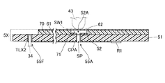
図5は荷重検知センサ5Xの構成を示す分解図である。また、図6は図5に示す荷重検知センサ5XのX−X線における断面図であり、図7は図5に示す荷重検知センサ5XのY−Y線における断面図である。
FIG. 5 is an exploded view showing the configuration of the load detection sensor 5X. 6 is a sectional view taken along line XX of the
図5〜図7に示すように、荷重検知センサ5Xは、第1電極シート50と、第2電極シート60と、スペーサ70とを主な構成として備える。
As shown in FIGS. 5 to 7, the load detection sensor 5 </ b> X includes a
第1電極シート50は、例えば可撓性を有さない絶縁性の基板51を有する。基板51の材料としては、フェノール樹脂あるいはエポキシ樹脂などが挙げられる。この基板51において第2電極シート60に対向される一方の面F1には、第1電極52及び第1接点部53が配置されている。
The
第1電極52は、スイッチSW1を構成する一方の電極であり、例えば円形の金属印刷層とされる。また、第1接点部53は、第2電極シート60と接触する概ね矩形の接触領域AR1と当該第2電極シート60とは非接触とされる非接触領域AR2とが互いに接続されて成る。
The
基板51において一方の面F1とは逆側の他方の面F2は荷重検知センサ5Xの下面とされ、当該他方の面F2には並列抵抗R1及び直列抵抗r1が配置される。これら並列抵抗R1及び直列抵抗r1は本実施形態ではチップ抵抗とされる。
In the
基板51には、当該基板51の一方の面F1から他方の面F2にまで貫通する複数の貫通孔が形成され、それぞれ第1シート貫通孔55A、第2シート貫通孔55B、固定用貫通孔55C,55D及びピン用貫通孔55E,55Fとされる。
The
第1シート貫通孔55Aは、基板51の一方の面F1のうち第1電極52が配置される領域内に開口が位置されるシート貫通孔である。第1シート貫通孔55A内には第1導電性部材CPAが設けられており、当該第1導電性部材CPAを介して、基板51の他方の面F2に配置される回路部位と第1電極52とが電気的に接続される。また、第1導電性部材CPAは第1シート貫通孔55Aの内周面上に設けられており、第1シート貫通孔55A内には、当該第1導電性部材CPAに囲まれる空気孔SPが形成される。
55 A of 1st sheet | seat through-holes are sheet | seat through-holes in which opening is located in the area | region where the
第2シート貫通孔55Bは、基板51の一方の面F1のうち第1接点部53が配置される領域内に開口が位置されるシート貫通孔である。本実施形態では、第1接点部53の非接触領域AR2内に第2シート貫通孔55Bの開口が位置される。
The second sheet through hole 55 </ b> B is a sheet through hole in which an opening is positioned in a region where the
第2シート貫通孔55B内には第2導電性部材CPBが充填されている。この第2導電性部材CPBを介して、基板51の他方の面F2に配置される回路部位と第1接点部53の非接触領域AR2とが電気的に接続される。
The second conductive member CPB is filled in the second sheet through
固定用貫通孔55C,55Dはハウジング3Xにおけるスイッチ収容部の底壁37に設けられる一対の固定用ピン33が挿通される貫通孔である。この固定用貫通孔55C,55Dの直径は一対の固定用ピン33の外径と同程度とされる。
The fixing through
ピン用貫通孔55E,55Fはハウジング3Xに設けられる一対の接続ピン34が挿通される貫通孔である。ピン用貫通孔55Eの内部には荷重検知センサ5Xにおける電気回路の一方の末端部位である端子TLX1が設けられ、ピン用貫通孔55Fの内部には荷重検知センサ5Xにおける電気回路の他方の末端部位である端子TLX2が設けられている。ピン用貫通孔55Eの内部に設けられる端子TLX1は直列抵抗r1と電気的に接続され、当該直列抵抗r1を介して第1接点部53と電気的に接続される。また、ピン用貫通孔55Fの内部に設けられる端子TLX2は第1電極52と並列抵抗R1との接点に電気的に接続され、当該並列抵抗R1を介して第1接点部53と接続される。また、端子TLX1,TLX2は、対応するピン用貫通孔55E,55Fの内周面に沿って設けられており、当該端子TLX1,TLX2に囲まれる空間の幅は接続ピン34の外径と同程度とされる。これらピン用貫通孔55E,55F一対の接続ピン34が挿通されると、端子TLX1と一方の接続ピン34が電気的に接続され、端子TLX2と他方の接続ピン34が電気的に接続される。これら接続ピン34は、上記のようにコネクタ31X(図1)の対応するコネクタ端子に電気的に接続され、ケーブル6(図1)を介して、エンジンコントロールユニットECU(図1)に接続される。
The pin through
第2電極シート60は、金属シート61と、第2電極62と、第2接点部63を主な構成として有する。
The
金属シート61は、可撓性を有する薄厚の金属シートであり、本実施形態では基板51の縦幅よりも短い縦幅を有し、当該基板51の横幅と同等の横幅を有する薄厚の直方体状とされる。金属シート61の材料としては、金属である限り特に限定するものではないが、例えば銅やステンレスなどが挙げられる。
The
金属シート61には、当該金属シート61の一方の面から他方の面にまで貫通する固定用貫通孔65C,65Dが形成される。固定用貫通孔65C,65Dはハウジング3Xにおけるスイッチ収容部の底壁に設けられる一対の固定用ピン33が挿通される貫通孔であり、第1電極シート50の基板51に形成される固定用貫通孔55C,55Dと同形同大とされる。また、固定用貫通孔65C,65Dに対する第2電極62及び第2接点部63の配置部位と、第1電極シート50における固定用貫通孔55C,55Dに対する第1電極52及び第1接点部53の配置部位とは相対的に同じ位置関係とされ、第1電極シート50と金属シート61とを重ねる場合に固定用貫通孔55Cと固定用貫通孔65Cとが互いにかなさり、固定用貫通孔55Dと固定用貫通孔65Dとが互いに重なる。
The
第2電極62は、スイッチSW1を構成する他方の電極であり、本実施形態では金属シート61においてスペーサ70を介して第1電極52と対向する部位とされる。すなわち、金属シート61の一部が第2電極62を兼ねている。なお、例えば、金属シート61と同じ材料又は異なる材料の金属層が、第2電極62として、金属シート61においてスペーサ70を介して第1電極52と対向する部位に配置されても良い。
The
第2接点部63は、接続維持部APを構成する一方の部材であり、本実施形態では板ばねとして形成される。すなわち、金属シート61には、当該金属シート61の一端から他端側に向かって延伸する一対の切り欠き61A及び61B(図1)が所定間隔をあけて設けられ、これら切り欠き61A及び61B(図1)に挟まれる部位が第2接点部63とされる。また、この第2接点部63が金属シート61のシート面に対して傾斜するように、当該第2接点部63の根元が第1電極シート50側に折り曲げられることによって、第2接点部63が板ばねとして形成される。このように金属シート61では第2電極62とされる部位とは異なる部位が第2接点部63とされる。第2接点部63が形成される位置は、第1電極シート50と第2電極シート60とが重ねられる場合に、第1接点部53の接触領域AR1と重なる位置とされる。なお、第2接点部63として形成される板ばねの形状は、例えば、根元の幅が開放端の幅よりも大きい台形状とされても良く、矩形や台形以外の種々の形状が適用可能である。また、第2接点部63として、金属シート61と同じ材料又は異なる材料の金属層が、金属シート61における第1電極シート50側に配置されても良い。
The
スペーサ70は、第1電極シート50と第2電極シート60との間に挟まれる薄厚の絶縁性部材であり、本実施形態では金属シート61から第2接点部63を除いたものと概ね同形同大とされる。スペーサ70の材料としてはPET、PI又はPEN等の樹脂が挙げられる。
The
このスペーサ70には開口71が形成されている。この開口71は、基板51に配置される第1電極52と、当該第1電極52に対向される金属シート61の第2電極62との間であって、鉛直方向において第1電極52及び第2電極62と重なる位置に形成されている。開口71の大きさは、第1電極52の大きさよりも僅かに小さい状態とされる。
An
またスペーサ70にはスリット状の開口72が形成される。この開口72は、基板51に配置される第1接点部53と、当該第1接点部53に対向される金属シート61の第2接点部63との間であって、鉛直方向において第1接点部53及び第2接点部63と重なる位置に形成されている。開口72の大きさは、金属シート61において第2接点部63として形成される板ばねの大きさよりも僅かに大きい状態とされる。
In addition, a slit-
さらにスペーサ70には、当該スペーサ70の一方の面から他方の面にまで貫通する固定用貫通孔75C,75Dが形成される。固定用貫通孔75C,75Dはハウジング3Xにおけるスイッチ収容部の底壁に設けられる固定用ピン33が挿通される貫通孔であり、第1電極シート50の基板51に形成される固定用貫通孔55C,55Dと同形同大とされる。また、スペーサ70における固定用貫通孔75C,75Dに対する開口71及び開口72の配置部位と、第1電極シート50における固定用貫通孔55C,55Dに対する第1電極52及び第1接点部53の配置部位とは相対的に同じ位置関係とされる。従って、第1電極シート50、スペーサ70、第2電極シート60を重ねる場合に、固定用貫通孔55Cと固定用貫通孔65Cと固定用貫通孔75Cとが互いに重なり、固定用貫通孔55Dと固定用貫通孔65Dと固定用貫通孔75Cとが互いに重なる。
Further, the
このような第1電極シート50、第2電極シート60及びスペーサ70が重ね合わされて荷重検知センサ5Xが構成される。荷重検知センサ5Xにおいては、図6に示すように、第1電極52と第2電極62とが開口71を介して互いに離間した状態で対向し、スイッチSW1が構成される。第1電極52と第2電極62とが離間した状態において、第1電極52と第2電極62との距離は、例えば、0.1mmとされる。そして、電極貫通孔52A内に形成される空気孔SPが、開口71に連通される。従って、第2電極62が撓んで第1電極52に接触する場合に、不要な空気を空気孔SPから荷重検知センサ5Xの外部に排出することができる。このように第1シート貫通孔55Aは、基板51の一方の面F1に配置される第1電極52と他方の面F2側に配置される回路部位とを電気的に接続させる為の孔のみならず、開口71内の空気を荷重検知センサ5Xの外部に排出する排気孔も兼ねている。
The
また、上記のように、荷重検知センサ5Xにおいては、第2電極シート60の第2接点部63が板ばねとして形成され、金属シート61のシート面に対して塑性変形をされ常時傾斜した状態にある。このため図7に示すように、第2接点部63が、スペーサ70の切り欠きで形成される開口72内を抜けて、第1電極シート50の第1接点部53の接触領域AR1と接続される。このように第1接点部53と第2接点部63とが接触することで接続維持部APが形成される。つまり、第1電極シート50の第1接点部53は、荷重検知センサユニットSUのハウジングカバー4Xに外圧が加わらない場合にも電気的な接続が維持される接続維持部APを構成する一方の部材であり、第2電極シート60の第2接点部63は当該接続維持部APを構成する他方の部材とされる。
Further, as described above, in the
このような荷重検知センサ5Xは、図3に示すように、ハウジング3Xにおける一対の固定用ピン33が第1電極シート50の固定用貫通孔55C,55D、スペーサ70の固定用貫通孔75C,75D及び第2電極シート60の固定用貫通孔65C,65Dに順に挿通されることで、ハウジング3Xに固定される。このとき第1電極52と台座2Xの載置面21Sとの間には、基板51及びハウジング3Xの底壁37が位置する。従って、基板51と底壁37はそれぞれ第1電極52を台座2X上で支える支持部材と理解することができる。
In such a
また、荷重検知センサ5Xがハウジング3Xに固定された状態で、一対の接続ピン34が第1電極シート50のピン用貫通孔55E,55Fにそれぞれ挿入される。これによりピン用貫通孔55E,55Fの内部に設けられる端子TLX1,TLX2は対応する接続ピン34と接触し、当該接続ピン34を介してハウジング3Xのコネクタ31Xのコネクタ端子と電気的に接続される。また、ハウジングカバー4Xが取り付けられることで、スイッチSWにおける第2電極62の第1電極52側と反対側に上記のようにスイッチ押圧部43の先端が接触する。
In addition, with the
次に、荷重検知センサ5XのスイッチSW1がオンになる動作について説明する。
Next, an operation for turning on the switch SW1 of the
座席に人が着座すると、人の荷重によりシートクッションSCの下面が下方に移動する。本実施形態では、一対のフック部22の上端部よりも上側にシートクッションSCの下面が位置する。従って、シートクッションSCの下面がそれぞれのSばね90を含むSばね面に対して傾斜していても、一対のフック部22の上端部がシートクッションSCの下面を押圧することで、シートクッションSCの下面の傾斜がある程度緩和する。
When a person sits on the seat, the lower surface of the seat cushion SC moves downward due to the load of the person. In the present embodiment, the lower surface of the seat cushion SC is positioned above the upper ends of the pair of
更にシートクッションSCの下面が下方に移動すると、シートクッションSCの下面は、一対のフック部22の上端部に押圧されることで変形しながらハウジングカバー4Xの上面47Sに接触する。このとき、シートクッションSCの下面は、上記のように傾斜が緩和されつつも、ある程度傾斜する場合がある。この場合、Sばね90に係止される台座2Xの載置面21Sに対してもシートクッションSCの下面は傾斜することとなり、載置面21S上に配置されるハウジングカバー4Xの上面47Sに対してもシートクッションSCの下面は傾斜する。
When the lower surface of the seat cushion SC further moves downward, the lower surface of the seat cushion SC comes into contact with the upper surface 47S of the
本実施形態では、上記のようにハウジングカバー4Xは荷重検知センサ5Xに接する軸部であるスイッチ押圧部43の先端を中心に傾くようにして回動することができるため、上面47Sは、載置面21Sに対する角度が変化するように動く。従って、シートクッションSCの下面はハウジングカバー4Xの上面47Sに対して傾斜していても、当該上面47SはシートクッションSCの下面に対して追随するようにして面接触することができる。
In the present embodiment, as described above, the
そして、更にシートクッションSCの下面が下方に移動すると、上記のようにハウジングカバー4Xとハウジング3Xとの間には隙間GAが形成されているため、ハウジングカバー4Xはこの隙間GAの範囲内で下方に移動する。
When the lower surface of the seat cushion SC further moves downward, the gap GA is formed between the
図8は、荷重検知センサ5Xのオン状態を示す図である。図8に示すように、ハウジングカバー4Xの下方への移動により、スイッチ押圧部43の先端が第2電極62を押圧すると、第2電極62は第1電極52に接触する。この結果、荷重検知センサ5XのスイッチSW1はオンとなる。このため、一対の端子TLX1,TLX2間の抵抗値が低くなり、この抵抗の変化がケーブル6(図1)を介してエンジンコントロールユニットECU(図1)により検知される。
FIG. 8 is a diagram illustrating an ON state of the
以上説明したように本実施形態の荷重検知装置100では、一対の端子8T1、8T2間に複数の荷重検知センサ5X〜5Zが互いに直列に接続される。それぞれの荷重検知センサ5X〜5Zは、互いに離間して対向される一対の電極で構成されるスイッチSW1〜SW3と、スイッチSW1〜SW3に対して直列に接続される直列抵抗r1〜r3と、スイッチSW1〜SW3に対して並列に接続される並列抵抗R1〜R3とを有する。
As described above, in the
このような荷重検知装置100では、荷重検知センサ5X〜5Zが各座席に1つずつ割り当てられる。これら荷重検知センサ5X〜5Zのうち着座状態にある座席に割り当てられる例えば荷重検知センサ5Xでは自身が有するスイッチSW1がオンとなり、当該荷重検知センサ5Xでの抵抗値は直列抵抗r1の値となる。一方、着座状態にはない座席に割り当てられる例えば荷重検知センサ5Yでは自身が有するスイッチSW2はオフとなり、当該荷重検知センサ5Yの抵抗値は直列抵抗r1と並列抵抗R1の合成抵抗の値となる。
In such a
本実施形態における荷重検知装置100では、各スイッチSW1〜SW3のオンとオフとの組み合わせごとに各荷重検知センサ5X〜5Zの合成抵抗の合計が異なる。
In the
このため、上記表1の「ショートなし」に示されているように、一対の端子8T1、8T2からみた端子間抵抗値は、それぞれの荷重検知センサ5X〜5ZのスイッチSW1〜SW3のオンとオフとの組み合わせごとに異なることになる。
For this reason, as shown in “No short” in Table 1 above, the inter-terminal resistance values viewed from the pair of terminals 8T1 and 8T2 are ON and OFF of the switches SW1 to SW3 of the respective
一方、これら荷重検知センサ5X〜5Zのうち、座席に着座する乗員が例えば飲み物をこぼす等してその座席に割り当てられる例えば荷重検知センサ5Zがショートする場合、当該荷重検知センサ5Zでの直列抵抗r1及び並列抵抗R1の合成抵抗はおおむねゼロとなる。
On the other hand, among the
本実施形態の荷重検知装置100では、各直列抵抗r1〜r3同士の抵抗値及び各並列抵抗R1〜R3同士の抵抗値が互いに異なり、荷重検知センサ5X、5Y、5Zそれぞれの直列抵抗r1、r2、r3と並列抵抗R1、R2、R3とが互いに異なっている。
In the
このため、上記表1の「ショートなし」以外に示されているように、残りの荷重検知センサ5X、5YのスイッチSW1、SW2のオンとオフとの組み合わせに応じて、当該荷重検知センサ5X〜5Zの合成抵抗の合計(和)も異なる。つまり、荷重検知センサ5X〜5Zの一部又は全部に故障があったとしても、一対の端子8T1、8T2からみた端子間抵抗値は、それぞれの荷重検知センサ5X〜5ZのスイッチSW1〜SW3のオンとオフとの組み合わせごとに異なることになる。
For this reason, as shown in Table 1 other than “No short”, the
従って、本実施形態の荷重検知装置100では、一対の端子8T1、8T2に電気的に接続されるエンジンコントロールユニットECUに対し、荷重検知装置100から一対の端子8T1、8T2を介して与えられる信号のレベルに基づいて複数の座席に対する着座の有無及び故障の有無を個別に検知させることができる。
Therefore, in the
また、本実施形態の場合、それぞれの荷重検知センサ5X〜5Zにおける並列抵抗R1〜R3の抵抗値のうち最小となる並列抵抗R1の抵抗値(400Ω)は、それぞれの荷重検知センサ5X〜5Zにおける直列抵抗r1〜r3の合成抵抗値(350Ω)よりも大きい。
In the case of the present embodiment, the resistance value (400Ω) of the parallel resistance R1 that is the minimum among the resistance values of the parallel resistances R1 to R3 in the
このため、故障がある場合における一対の端子8T1、8T2からみた端子間抵抗値の変化に比べ、着座がある場合における一対の端子8T1、8T2からみた端子間抵抗値の変化が大きくなる。また、検知を優先しない方に相当する直列抵抗r1〜r3の抵抗値の変化幅は、当該検知を優先する方に相当する並列抵抗R1〜R3の抵抗値の最小の抵抗値よりも小さくなる。従って、着座を優先して検知することが可能となる。 For this reason, compared with the change of the resistance value between terminals seen from a pair of terminals 8T1 and 8T2 when there is a failure, the change of the resistance value between terminals seen from a pair of terminals 8T1 and 8T2 when there is a seating becomes larger. In addition, the change width of the resistance value of the series resistors r1 to r3 corresponding to the one not giving priority to detection is smaller than the minimum resistance value of the resistance values of the parallel resistors R1 to R3 corresponding to the one giving priority to the detection. Therefore, it is possible to detect seating with priority.
また、本実施形態の場合、それぞれの荷重検知センサ5X〜5Zにおける並列抵抗R1〜R3の抵抗値は、それぞれの荷重検知センサ5X〜5Zにおける直列抵抗r1〜r3の抵抗値よりも大きい。
In the case of the present embodiment, the resistance values of the parallel resistors R1 to R3 in the respective
従って、一般的に生じ難い故障よりも優先して荷重をより容易に検知することが可能となる。 Therefore, the load can be detected more easily in preference to a failure that is generally difficult to occur.
さらに、本実施形態の場合、荷重検知センサ5X〜5Zごとにコネクタ31X〜31Zが接続され、それぞれの荷重検知センサ5X〜5Zが個々にコネクタ31X〜31Zにより着脱可能とされる。
Furthermore, in the case of this embodiment, the
従って、荷重検知センサ5X〜5Zのうち例えば1つの荷重検知センサ5Xが故障した場合に、荷重検知センサ5X〜5Z全体を取り換えずに、当該故障した荷重検知センサ5Xだけを簡易に取り換えることができる。
Therefore, for example, when one of the
さらに、本実施形態の場合、複数の荷重検知センサ5X〜5Zそれぞれの並列抵抗R1〜R3及び直列抵抗r1〜r3は、チップ抵抗とされる。
Further, in the case of the present embodiment, the parallel resistors R1 to R3 and the series resistors r1 to r3 of each of the plurality of
チップ抵抗は一般的に印刷抵抗に比べて抵抗値を正確に設定することができるので、本実施形態では、複数の座席に対する着座の有無及び故障の有無をより明瞭に検知させることができる。 In general, the resistance value of the chip resistor can be set more accurately than the printing resistor. Therefore, in this embodiment, the presence / absence of seating and the presence / absence of failure can be detected more clearly.
さらに、本実施形態の場合、荷重検知センサ5X〜5Zは、第1電極52を有する基板51と、当該基板51の一方の面F1上にスペーサ70を介して配置され第2電極62を有する第2電極シート60とを含む。そして、チップ抵抗でなる並列抵抗R1〜R3及び直列抵抗r1〜r3が、スペーサ70が対向する基板51の一方の面F1とは逆側の他方の面F2上に配置される。
Further, in the case of the present embodiment, the
チップ抵抗の厚みは一般的に印刷抵抗の厚みに比べて大きくなるが、本実施形態では、基板51のうち第2電極62に対向する第1電極52が配置されている側とは逆側の他方の面F2上に配置されるので、チップ抵抗の厚みによって荷重検知センサ5Xの感度が悪くなることを回避することができる。
Although the thickness of the chip resistor is generally larger than the thickness of the printing resistor, in this embodiment, the side of the
ところで、本実施形態の荷重検知センサ5Xでは、第1電極シート50の第1接点部53と第2電極シート60の第2接点部63とを介して第1電極シート50に形成される回路部位と第2電極シート60に形成される回路部位とが常時的に導通状態にある。このため、第1電極シート50に一対の端子TLX1,TLX2それぞれを配置することができる。
By the way, in the
また、本実施形態の荷重検知センサ5Xでは、第2電極シート60において第2接点部63を含む部位は、当該第2接点部63を第1接点部53に押し付ける板ばねとされている。このため第1接点部53と第2接点部63を常に接続状態に維持するための他の部材を不要とすることができる。従って、部品点数が増えることを抑えると共に小型化が可能となる。
Further, in the load detection sensor 5 </ b> X of the present embodiment, a portion including the
また、本実施形態の荷重検知センサ5Xでは、第2電極シート60は金属シート61でなる。このため、第2電極シート60における熱による影響が少ないため、高温環境化や低温環境下で用いても、荷重検知センサ5Xの感度が安定する。また、第2電極シート60が金属であるため、破損等を低減させることができ、耐久性を向上させることができる。さらに、第2電極シート60において板ばねとされる第2接点部63も金属となるため、樹脂シートの一部が板ばねとされる場合に比べて、当該板ばねとして形成される第2接点部63の展性及び延性を大きくすることができる。従って、板ばねとして形成される第2接点部63が折れるなどの破損を低減させ、当該板ばねの耐久性を向上させることができる。
Further, in the load detection sensor 5 </ b> X of the present embodiment, the
また、本実施形態の荷重検知センサ5Xでは、第1電極シート50のシートとなる基板51は、第2電極シート60に対向される一方の面F1から他方の面F2にまで貫通する第1シート貫通孔55Aを有する。また、第1電極52は、第1シート貫通孔55A内に設けられる第1導電性部材CPAを通じて、基板51の他方の面F2に配置される回路部位と電気的に接続されている。このため、基板51の他方の面F2に一方の端子TLX1を取り出すことが可能となる。本実施形態のように、第1シート貫通孔55Aとは別のピン用貫通孔55Eの内部に端子TLX1を配置することも可能である。従って、荷重検知センサユニットSUをコネクタ31Xなどの他の電子部品と接続する場合に簡易となる。また、回路部位を他方の面F2に設けることができるため、一方の面F1に回路部位を設ける必要がなくなり、一方の面F1の回路部位による凹凸を少なくすることができる。これにより、荷重検知センサ5Xの感度を安定させることができる。
In the load detection sensor 5 </ b> X of the present embodiment, the first sheet that penetrates from the one surface F <b> 1 facing the
さらに本実施形態の荷重検知センサ5Xでは、第1シート貫通孔55Aにおける一方の面側の開口は、基板51の一方の面F1において第1電極52が配置される領域に位置される。また、第1シート貫通孔55Aは、第1電極52に設けられる電極貫通孔52Aを介して、第1電極52と第2電極62との間の開口71に連通される空気孔SPを有する。このため、第1シート貫通孔55Aが、基板51の一方の面F1に配置される第1電極52を、当該基板51の他方の面側に回路部位と電気的に接続するための接続用孔のみならず、スペーサの空気を外部に排出する排気孔も兼ねることになる。このため、接続用孔と排気孔とを別々に設ける場合に比べて基板51の耐久性を向上させることができる。また、排気孔を別途設ける必要がなくなり、省スペース化が可能となる。
Furthermore, in the load detection sensor 5 </ b> X of the present embodiment, the opening on the one surface side of the first sheet through hole 55 </ b> A is located in the region where the
さらに本実施形態の荷重検知センサ5Xでは、第1電極シート50のシートとなる基板51は、第1シート貫通孔55Aとは異なる位置に、第2電極シート60に対向される一方の面F1から他方の面F2にまで貫通する第2シート貫通孔55Bを有する。また、第1接点部53は、第2シート貫通孔55B内に設けられる第2導電性部材CPBを通じて、基板51の他方の面F2に配置される回路部位と電気的に接続されている。このため、基板51の他方の面F2に一対の端子TLX1,TLX2を取り出すことが可能となる。本実施形態のように、第1シート貫通孔55Aとは別のピン用貫通孔55E,55Fの内部に端子TLX1,TLX2を配置することも可能である。従って、荷重検知センサユニットSUをコネクタ31Xなどの他の電子部品と接続する場合に簡易となる。また、回路部位を他方の面F2に設けることができるため、一方の面F1に回路部位を設ける必要がなくなり、一方の面F1の回路部位による凹凸を少なくすることができる。これにより、荷重検知センサ5Xの感度を安定させることができる。
Furthermore, in the
さらに本実施形態の荷重検知センサ5Xでは、基板51の他方の面F2に並列抵抗R1及び直列抵抗r1が配置されている。このため、並列抵抗R1及び直列抵抗r1の厚みが大きい場合であっても、その厚みによって荷重検知センサ5Xの感度が悪くなることを回避することができる。
Further, in the
なお、本実施形態では、第1電極シート50における回路部位、直列抵抗r1及び並列抵抗R1は基板51の他方の面F2に設けられ、一対の端子TLX1,TLX2はピン用貫通孔55E,55F内に設けられている。このため、基板51の一方の面F1から第1電極52、及び、第1接点部53以外の部品を排除することができる。従って、基板51の一方の面F1において他の部品による凹凸がなくすことができ、荷重検知センサ5Xの感度がより向上させることができる。
In the present embodiment, the circuit portion, the series resistance r1 and the parallel resistance R1 in the
(2)第2実施形態
次に、本発明の第2実施形態について説明する。なお、本実施形態を説明するにあたり、第1実施形態と同一又は同等の構成要素については、同一の参照符号を付して特に説明する場合を除き重複する説明は省略する。
(2) Second Embodiment Next, a second embodiment of the present invention will be described. In the description of the present embodiment, the same or equivalent components as those in the first embodiment are denoted by the same reference numerals, and redundant description is omitted unless specifically described.
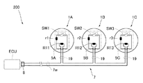
図9は、第2実施形態における荷重検知装置200の構成を示す模式図である。図9に示すように、本実施形態における荷重検知装置200は、複数の荷重検知センサユニット1A〜1Cと、ケーブル7とによって構成される。
FIG. 9 is a schematic diagram illustrating the configuration of the
それぞれの荷重検知センサユニット1A〜1Cは例えば車両の座席装置におけるシートクッションの下方にそれぞれ配置され、1つのシートクッションにつき1つの荷重検知センサユニット1A、1B、1Cが割り当てられる。
Each of the load
荷重検知センサユニット1Aは、スイッチSW1と、直列抵抗r1及び並列抵抗R11を有する荷重検知センサ5Aを備える。並列抵抗R11は、スイッチSW1及び直列抵抗r1に対して並列に接続されている。この荷重検知センサユニット1Aでは、上記第1実施形態のようなコネクタ31Xはなく、荷重検知センサ5Aの配線とケーブル7の配線とが例えばはんだ付けや溶接等により電気的及び機械的に接続される。
The load
荷重検知センサユニット1Bは、スイッチSW2と、直列抵抗r2及び並列抵抗R12を有する荷重検知センサ5Bを備える。並列抵抗R12は、スイッチSW2及び直列抵抗r2に対して並列に接続されている。この荷重検知センサユニット1Bでは、上記第1実施形態のようなコネクタ31Yはなく、荷重検知センサ5Bの配線とケーブル7の配線とが例えばはんだ付けや溶接等により電気的及び機械的に接続される。
The load
荷重検知センサユニット1Cは、スイッチSW3と、直列抵抗r3及び並列抵抗R13を有する荷重検知センサ5Cを備える。並列抵抗R13は、スイッチSW3及び直列抵抗r3に対して並列に接続されている。この荷重検知センサユニット1Cでは、上記第1実施形態のようなコネクタ31Zはなく、荷重検知センサ5Cの配線とケーブル7の配線とが例えばはんだ付けや溶接等により電気的及び機械的に接続される。
The load
ケーブル7は、それぞれの荷重検知センサユニット1A〜1CとエンジンコントロールユニットECUとを接続するものであり、エンジンコントロールユニット側のコネクタ8とを有する。このケーブル7には、上記第1実施形態のケーブル6における荷重検知センサユニット側のコネクタ9X〜9Zはなく、エンジンコントロールユニット側のコネクタ8に接続されるケーブル配線7wの所定部位にそれぞれの荷重検知センサ5A〜5Cの信号ケーブル19が接続されている。
The
図10は、第2実施形態における荷重検知装置200の等価回路を示す図である。図10に示すように、荷重検知装置200では、ケーブル7におけるコネクタ8の一対の端子8T1、8T2間にそれぞれの荷重検知センサ5A〜5Cが配置され、当該荷重検知センサ5A〜5Cはケーブル7を介して直列に接続される。
FIG. 10 is a diagram illustrating an equivalent circuit of the
各スイッチSW1〜SW3のオンとオフとの組み合わせごとにそれぞれの荷重検知センサ5A〜5Cの合成抵抗の合計は異なっている。また、各直列抵抗r1〜r3同士の抵抗値及び各並列抵抗R11〜R13同士の抵抗値が互いに異なり、荷重検知センサ5A、5B、5Cそれぞれの直列抵抗r1、r2、r3と並列抵抗R11、R12、R13とが互いに異なっている。
The total combined resistance of the
本実施形態の場合、それぞれ並列抵抗R11〜R13の抵抗値は直列抵抗r1〜r3の抵抗値よりも大きくされ、当該並列抵抗R11〜R13の抵抗値のうち最小の抵抗値は直列抵抗r1〜r3の合成抵抗値よりも大きくされる。例えば、上記第1実施形態と同様に、直列抵抗r1、r2、r3の抵抗値と並列抵抗R1、R2、R3の抵抗値とは、ともに、1:2:4とされる。 In the case of the present embodiment, the resistance values of the parallel resistors R11 to R13 are made larger than the resistance values of the series resistors r1 to r3, respectively, and the minimum resistance value among the resistance values of the parallel resistors R11 to R13 is the series resistors r1 to r3. The combined resistance value is made larger. For example, as in the first embodiment, the resistance values of the series resistors r1, r2, and r3 and the resistance values of the parallel resistors R1, R2, and R3 are all 1: 2: 4.
このような荷重検知装置200では、上記第1実施形態と同様に、荷重検知センサ5A〜5Cがショートしていない場合、荷重検知センサ5A〜5Cの1つ、2つ又は全てがショートしている場合、当該荷重検知センサ5A〜5Cのオンとオフとの組み合わせごとにそれぞれの荷重検知センサ5A〜5Cの合成抵抗の合計は異なる。
In such a
次に、荷重検知センサユニット1A〜1Cの構成について説明する。ただし、荷重検知センサユニット1A〜1Cの構成は同じであるため、当該荷重検知センサユニット1Aの構成についてのみ説明する。
Next, the configuration of the load
図11は第2実施形態における荷重検知センサユニット1Aの構成を示す分解図であり、図12は図11の荷重検知センサユニット1Aを別の角度から見た図である。また、図13は、図11、図12の荷重検知センサユニット1Aの断面図である。なお、図13は、当該図の複雑化することを避けるため荷重検知センサ5Aを簡略化している。
FIG. 11 is an exploded view showing the configuration of the load
図11〜13に示すように、本実施形態の荷重検知センサユニット1Aは、ハウジング3A、ハウジングカバー4A及び荷重検知センサ5Aを主な構成として備える。なお、図8から図10には台座が記載されていないが、本実施形態において荷重検知センサユニット1Aは台座を備えていても良く備えていなくても良い。
As shown in FIGS. 11 to 13, the load detection sensor unit 1 </ b> A of the present embodiment includes a housing 3 </ b> A, a
図11、図12に示すように、ハウジング3Aは、底壁87と、複数の枠壁88と、複数のアーム81とを有する。底壁87は、概ね円形の板状の形状をしており、底壁87の外周の3カ所に枠壁88が接続されている。枠壁88は、外側の形状が概ね底壁87の外周と同様の形状をしており、内側の形状が平面状とされている。また、底壁87には、複数の貫通孔30Hが形成されている。
As shown in FIGS. 11 and 12, the housing 3 </ b> A includes a
それぞれの枠壁88は、概ね円形の底壁87の概ね中心を基準として、互いに90度をなす方向に配置されており、互いに隣り合う枠壁88の内側面が互いに90度をなし、互いに向かい合う枠壁88の内側面89が互いに対向している。これらの内側面89は、互いに隣り合う貫通孔30Hの中心を結ぶ線のいずれかと概ね平行とされている。また、それぞれの枠壁88の外周には、アーム81が接続されている。それぞれのアーム81には開口82が穿設される。また、枠壁88およびアーム81は、本実施形態では3カ所とされ、荷重検知センサユニット1Aが延在する方向には設けられていない。
The
ハウジングカバー4Aは、底壁87及び枠壁88を覆う蓋部材であり、図13に示すシートクッションSCに押圧されることで荷重検知センサ5AのスイッチSW1を押圧する押圧部材である。ハウジングカバー4Aは、頂壁45及び枠壁48bを有する。頂壁45は概ね円形での板状部材である。また、ハウジングカバー4Aの枠壁48bは複数に分割されて、頂壁45の外周状に接続されている。複数に分割されている枠壁48bの各間において、フック片48aが頂壁45に接続されている。それぞれのフック片48aは、ハウジング3Aのアーム81に形成される開口82に嵌め込まれる構成とされる。それぞれのフック片48aが開口82に嵌め込まれることで、底壁87や頂壁45の面方向に沿ったハウジング3Aとハウジングカバー4Aとの相対的な移動が規制される。
The
ハウジングカバー4Aの頂壁45には、ハウジング3Aの底壁87に対向される内側面から突出するスイッチ押圧部46が設けられている。スイッチ押圧部46は、先端が平面状とされること以外は、第1実施形態のスイッチ押圧部43と同様の形状とされるが、先端の形状が凸状の曲面形状とされても良い。また、ハウジングカバー4Aの頂壁45には、スイッチ押圧部46が設けられる側と同じ側の内側面から突出する複数のリブ49が設けられている。これらのリブ49は、ハウジング3Aの底壁87に形成される複数の貫通孔30Hと重なる位置に形成されている。これらのリブ49は、ハウジングカバー4Aがハウジング3Aを覆いそれぞれの開口82にそれぞれのフック片48aが嵌め込まれた状態で、各貫通孔30Hに挿入される。また、スイッチ押圧部46は、この状態で、先端が荷重検知センサ5Aと接触する。従って、第1実施形態のスイッチ押圧部43と同様にして、スイッチ押圧部46の先端は、後述のようにハウジングカバー4AがシートクッションSCに押圧されていない状態において、当該先端が荷重検知センサ5AのスイッチSW1と接触している。
A
なお、本実施形態においても第1実施形態と同様にハウジングカバー4Aは、シートクッションSCよりも硬質な材料から形成されており、ハウジングカバー4Aの一部であるスイッチ押圧部46もシートクッションSCよりも硬質な材料から形成されている。従って、本実施形態のハウジングカバー4Aは、第1実施形態のハウジングカバー4Aと同様の材料から成る。
In the present embodiment as well, the
このようにハウジングカバー4Aのスイッチ押圧部46が荷重検知センサ5Aに接触した状態で、図13に示すようにハウジングカバー4Aの頂壁45とハウジング3Aの枠壁88とは、離間しており、隙間GAが形成されている。
Thus, with the
このように組み上げられた荷重検知センサユニット1Aが座席装置のシートクッションSCの下方に配置された状態で、ハウジングカバー4Aの頂壁45における上面45Sは、シートクッションSCの下面と所定の距離を空けて対向する。この上面45Sは平面状とされる。上面45SはシートクッションSCからの押圧を受ける受圧面であり、荷重検知センサユニット1Aの受圧面と理解することができ、上面45Sの面積はスイッチ押圧部46における荷重検知センサ5Aと接触する部分の面積よりも大きくされている。
With the load
次に、本実施形態の荷重検知センサ5Aについて説明する。
Next, the
図14は、図11、図12の荷重検知センサ5Aを示す分解図である。ただし、理解の容易のため、図11及び図12と、図14とで見る方向を変えている。図11から図14に示すように、本実施形態の荷重検知センサ5Aは、スイッチSWを有するスイッチシート50Aと、金属板60Aとを備える。
FIG. 14 is an exploded view showing the
図11、図12に示すように、本実施形態のスイッチシート50Aは、シート状のメンブレンスイッチとされる。スイッチシート50Aは、概ね矩形のメインブロック50mと、メインブロック50mに接続されメインブロック50mよりも幅の狭いテールブロック50tとを有する。メインブロック50mにはスイッチSWが設けられている。また、テールブロック50tには幅の広い羽根部50fが形成されている。また、メインブロック50mの各頂点付近には、貫通孔50Hが形成されている。
As shown in FIGS. 11 and 12, the
図14に示すように、本実施形態のスイッチシート50Aは、第1電極シート56とスペーサ58と第2電極シート57とを備える。
As shown in FIG. 14, the
第1電極シート56は、第1絶縁シート56sと、第1電極56eと、第1端子56cとを主な構成として有する。
The
第1絶縁シート56sは、可撓性を有する絶縁性のシートとされ、スイッチシート50Aのメインブロック50mと同形状のメインブロック56mと、メインブロック56mに接続されスイッチシート50Aのテールブロック50tと概ね同形状のテールブロック56tとから成る。テールブロック56tの形状は、メインブロック56mと反対側の先端部位がテールブロック56tの他の部位よりも狭い幅となっている点において、スイッチシート50Aのテールブロック50tの形状と異なる。また、メインブロック56mには、スイッチシート50Aの貫通孔50Hと同様の位置に貫通孔56Hが形成されている。このような第1絶縁シート56sの材料としては、PET、PI又はPEN等の樹脂を挙げることができる。
The first insulating
第1電極56eは、メインブロック56mの概ね中央における一方の面上に設けられている。第1電極56eは、導体の層からなり、例えば略円形の金属印刷層とされる。第1端子56cは、導体の層からなり、例えば略四角形の金属層とされる。第1端子56cは、テールブロック56tの上記先端部位における第1電極56eが設けられている側の面上に設けられている。また、第1電極56eと第1端子56cとは第1配線56wを介して互いに電気的に接続されている。
The
第2電極シート57は、第2絶縁シート57sと、第2電極57eと、第2端子57cと、直列抵抗r1とを主な構成として有する。
The
第2絶縁シート57sは、第1絶縁シート56sと同様の絶縁性のシートとされる。本実施形態の場合、第2絶縁シート57sは、第1絶縁シート56sのメインブロック56mと同じ形状のメインブロック57mと、メインブロック57mに接続され第1絶縁シート56sのテールブロック56tと先端部位以外の形状が同じ形状のテールブロック57tとから成る。テールブロック57tの先端部位はテールブロック57tの他の部位よりも狭い幅とされており、第1絶縁シート56sと第2絶縁シート57sとを重ねたときに、第1絶縁シート56sのテールブロック56tにおける先端部位と第2絶縁シート57sのテールブロック57tにおける先端部位とが互いに重ならないようにされている。また、メインブロック57mには、第1絶縁シート56sと同様にして、スイッチシート50Aの貫通孔50Hと同様の位置に貫通孔57Hが形成されている。第2絶縁シート57sの材料としては、第1絶縁シート56sと同様に、PET、PI又はPEN等の樹脂を挙げることができ、第2絶縁シート57sの材料は、第1絶縁シート56sの材料と同じであっても異なっていても良い。
The second insulating
第2電極57eは、第1電極56eと同様の構成とされ、第2絶縁シート57sのメインブロック57mの概ね中央における一方の面上に設けられている。また、第2電極57eが設けられる位置は、第1電極シート56と第2電極シート57とを重ねたときに第1電極56eと重なる位置とされる。第2端子57cは、第1端子56cと同様の構成とされ、テールブロック57tの上記先端部位における第2電極57eが設けられている側の面上に設けられている。また、上記のように、第1絶縁シート56sと第2絶縁シート57sとを重ねるとき、それぞれの絶縁シートの先端部位が互いに重ならないため、第1端子56c及び第2端子57cは、第1絶縁シート56sと第2絶縁シート57sとの間に位置せずに露出する。また、第2電極57eと第2端子57cとは第2配線57wを介して互いに電気的に接続されている。
The
直列抵抗r1は、第2配線57wの中途部位に配置されており、当該第2配線57wと電気的及び機械的に接続されている。この直列抵抗r1は上記第1実施形態ではチップ抵抗とされたが、本実施形態では印刷抵抗とされる。第1絶縁シート56sと第2絶縁シート57sとがスペーサ58を挟んで貼着される場合に、直列抵抗r1の厚みに起因して、第1絶縁シート56sの第1電極56eと第2絶縁シート57sの第2電極57eとの距離が大きくなることを防止している。
The series resistor r1 is disposed in the middle of the
スペーサ58は、可撓性を有する絶縁性のシートとされ、メインブロック58mと、メインブロック58mに接続されるテールブロック58tとから成る。メインブロック58mは、外形が第1絶縁シート56s、第2絶縁シート57sのメインブロック56m,57mの外形と同様とされる。また、メインブロック58mには、中央に開口58cが形成されており、また、第1絶縁シート56s、第2絶縁シート57sと同様にして、スイッチシート50Aの貫通孔50Hと同様の位置に貫通孔58Hが形成されている。テールブロック58tは、第1絶縁シート56s、第2絶縁シート57sのテールブロック56t,57tにおける幅が狭い先端部位を除く形状とされる。
The
開口58cは、略円形の形状であり、第1電極56e及び第2電極57eの直径よりも直径が僅かに小さく形成されている。そして、開口58cは、スペーサ58を第1電極シート56及び第2電極シート57と重ね合わせて、スペーサ58を平面視する場合に、開口58cが第1電極56e及び第2電極57e周縁の内側に位置するように形成されている。さらにスペーサ58には、開口58c内の空間とスイッチシート50Aの外部の空間とを接続するスリット58bが形成されている。このスリット58bは、第1電極シート56、スペーサ58、第2電極シート57をそれぞれ重ねたときに、エアベントとされる。
The
スペーサ58の材料としては、第1絶縁シート56s及び第2絶縁シート57sと同様に、PET、PI又はPEN等の樹脂を挙げることができる。なお、スペーサ58の材料は、第1絶縁シート56s又は第2絶縁シート57sの材料と同じであっても異なっていても良い。また、スペーサ58の両面には、第1電極シート56及び第2電極シート57と接着されるための図示しない接着剤が塗布されている。
As the material of the
これらの第1電極シート56とスペーサ58と第2電極シート57とがこの順に貼着された状態で、第1電極シート56の第1電極56e、第1配線56w、及び、第2電極シート57の第2電極57e、第2配線57wは、第1絶縁シート56sと第2絶縁シート57sとの間に位置する。そして、第1電極56eと第2電極57eとが開口58cを介して対向してスイッチSW1を構成する。また、第1電極シート56とスペーサ58と第2電極シート57とが重ねられた状態で、それぞれの貫通孔56H,57H,58Hが互いに重なり、スイッチシート50Aの貫通孔50Hとなる。
With the
スイッチシート50Aの第1端子56c及び第2端子57cには、荷重検知センサユニット1Aにおけるコネクタ31X(図9)のコネクタ端子に接続される信号ケーブル19がそれぞれ接続されている。また、第1端子56cと第2端子57cとの間には並列抵抗R11が配置される。この並列抵抗R11に接続される一方の配線が第1端子56cに接続されるとともに、当該並列抵抗R11に接続される他方の配線が第2端子57cに接続されている。
The
第1端子56c及び第2端子57cと、当該第1端子56c及び第2端子57cに接続された並列抵抗R11及び信号ケーブル19の一部を含むスイッチシート50Aのテールブロック50tの端部は、図11、図12に示すように、端子封止樹脂18により覆われている。この端子封止樹脂18は、例えば、ホットメルトや光硬化樹脂等から成る。こうして、それぞれの信号ケーブル19及び並列抵抗R11が第1端子56c及び第2端子57cから外れることが抑制されると共に、第1端子56c及び第2端子57cが導電性の塵埃等により短絡することが抑制されている。なお、信号ケーブル19は、図9、図10に示すように、ケーブル7のケーブル配線7wに接続される。
The ends of the
また、金属板60Aは、可撓性を有する金属の板材から成る。金属板60Aは、例えば、第1実施形態における第2電極シート60の金属シート61と同様の材料から成る。金属板60Aは、スイッチシート50Aのメインブロック50mと概ね同じ形状とされ、スイッチシート50Aの貫通孔50Hと同様の位置に貫通孔60Hが形成されている。従って、スイッチシート50Aと金属板60Aとを重ねたときに、スイッチシート50Aの貫通孔50Hと金属板60Aの貫通孔60Hとが互いに重なる。また、スイッチシート50Aと金属板60Aとを重ねたときに、金属板60Aは、スイッチシート50AのスイッチSWを覆う。具体的には、図11から明らかなように、金属板60Aは、第1絶縁シート56sのスペーサ58とは反対側に設けられ、第1電極56e、第2電極57eのうちシートクッションSC側に位置する第1電極56eをシートクッションSC側から覆っている。なお、本実施形態では、金属板60Aと第1絶縁シート56s(スイッチシート50A)とは互いに非接着とされるが、互いに接着されていても良い。
The
以上説明したように本実施形態の荷重検知装置200では、一対の端子8T1、8T2間に複数の荷重検知センサ5A〜5Cが互いに直列に接続される。それぞれの荷重検知センサ5A〜5Cは、スイッチSW1〜SW3と、直列抵抗r1〜r3と、スイッチSW1〜SW3及び直列抵抗r1〜r3に対して並列に接続される並列抵抗R11〜R13とを有する。
As described above, in the
このような荷重検知装置200では、荷重検知センサ5A〜5Cのうち着座状態にある座席に割り当てられる例えば荷重検知センサ5Aでは自身が有するスイッチSW1がオンとなり、当該荷重検知センサ5Aでの抵抗値はr1と並列抵抗R11の合成抵抗の値となる。一方、着座状態にはない座席に割り当てられる例えば荷重検知センサ5Bでは自身が有するスイッチSW2はオフとなり、当該荷重検知センサ5Bの抵抗値は並列抵抗R12の値となる。
In such a
本実施形態における荷重検知装置200では、各スイッチSW1〜SW3のオンとオフとの組み合わせごとに各荷重検知センサ5A〜5Cの合成抵抗の合計が異なる。
In the
このため、一対の端子8T1、8T2からみた端子間抵抗値は、上記第1実施形態と同様に、それぞれの荷重検知センサ5A〜5CのスイッチSW1〜SW3のオンとオフとの組み合わせごとに異なることになる。
For this reason, the resistance value between terminals seen from the pair of terminals 8T1 and 8T2 is different for each combination of ON and OFF of the switches SW1 to SW3 of the
一方、これら荷重検知センサ5A〜5Cのうち、座席に着座する乗員が例えば飲み物をこぼす等してその座席に割り当てられる例えば荷重検知センサ5Aがショートする場合、当該荷重検知センサ5Aでの直列抵抗r1及び並列抵抗R11の合成抵抗はおおむねゼロとなる。
On the other hand, among the
本実施形態の荷重検知装置200では、各直列抵抗r1〜r3同士の抵抗値及び各並列抵抗R11〜R13同士の抵抗値が互いに異なり、荷重検知センサ5A、5B、5Cそれぞれの直列抵抗r1、r2、r3と並列抵抗R11、R12、R13とが互いに異なっている。
In the
このため、上記第1実施形態と同様に、残りの荷重検知センサ5B、5CのスイッチSW2、SW3のオンとオフとの組み合わせに応じて、当該荷重検知センサ5A〜5Cの合成抵抗の合計(和)も異なる。つまり、荷重検知センサ5A〜5Cの一部又は全部に故障があったとしても、一対の端子8T1、8T2からみた端子間抵抗値は、上記第1実施形態と同様に、それぞれの荷重検知センサ5A〜5CのスイッチSW1〜SW3のオンとオフとの組み合わせごとに異なることになる。
For this reason, as in the first embodiment, the total (sum) of the combined resistances of the
この結果、本実施形態の場合であっても、一対の端子8T1、8T2に電気的に接続されるエンジンコントロールユニットECUに対し、荷重検知装置100から一対の端子8T1、8T2を介して与えられる信号のレベルに基づいて複数の座席に対する着座の有無及び故障の有無を個別に検知させることができる。
As a result, even in the case of the present embodiment, signals given from the
以上、本発明の荷重検知装置について上記実施形態を例に説明したが、本発明は上記実施形態に限定されるものではない。 As mentioned above, although the said embodiment was demonstrated to the example about the load detection apparatus of this invention, this invention is not limited to the said embodiment.
例えば、上記第1実施形態では、それぞれの荷重検知センサユニット1X〜1Zにおける荷重検知センサ5X〜5Zの並列抵抗R1〜R3が、スイッチSW1〜SW3に対して並列に接続された。また上記第2実施形態では、それぞれの荷重検知センサユニット1A〜1Cにおける荷重検知センサ5A〜5Cの並列抵抗R11〜R13が、スイッチSW1〜SW3及び直列抵抗r1〜r3に対して並列に接続された。しかしながら、上記第1実施形態におけるそれぞれの荷重検知センサ5X〜5Zの並列抵抗R1〜R3がスイッチSW1〜SW3及び直列抵抗r1〜r3に対して並列に接続されていても良い。また、上記第2実施形態におけるそれぞれの荷重検知センサ5A〜5Cの並列抵抗R11〜R13がスイッチSW1〜SW3だけに対して並列に接続されていても良い。
For example, in the first embodiment, the parallel resistors R1 to R3 of the
また、上記実施形態では、並列抵抗R1〜R3、R11〜R13の抵抗値のうち最小となる並列抵抗R1、R11の抵抗値が、直列抵抗r1〜r3の合成抵抗値(それぞれの直列抵抗r1〜r3の合計の抵抗値)よりも大きくされた。しかしながら、直列抵抗r1〜r3の抵抗値のうち最小の抵抗値が並列抵抗R1〜R3、R11〜R13の合成抵抗値よりも大きくされていても良い。
このようにした場合、着座がある場合における一対の端子8T1、8T2からみた端子間抵抗値の変化に比べ、故障がある場合における一対の端子8T1、8T2からみた端子間抵抗値の変化が大きくなる。また、検知を優先しない方に相当する並列抵抗R1〜R3、R11〜R13の抵抗値の変化幅は、当該検知を優先する方に相当する直列抵抗r1〜r3の抵抗値の最小の抵抗値よりも小さくなる。従って、故障を優先して検知することが可能となる。このように故障を優先して検知する場合には有用となる。
Moreover, in the said embodiment, the resistance value of parallel resistance R1, R11 which becomes the minimum among the resistance values of parallel resistance R1-R3, R11-R13 is combined resistance value of series resistance r1-r3 (each series resistance r1- (total resistance value of r3). However, the minimum resistance value among the resistance values of the series resistors r1 to r3 may be larger than the combined resistance value of the parallel resistors R1 to R3 and R11 to R13.
In this case, the change in the resistance value between the terminals viewed from the pair of terminals 8T1 and 8T2 when there is a failure is larger than the change in the resistance value between the terminals 8T1 and 8T2 when there is a seating. . In addition, the change widths of the resistance values of the parallel resistors R1 to R3 and R11 to R13 corresponding to those not prioritizing detection are smaller than the minimum resistance values of the resistance values of the series resistors r1 to r3 corresponding to those prioritizing the detection. Becomes smaller. Therefore, it becomes possible to detect failure with priority. Thus, it is useful when priority is given to detecting a failure.
なお、上記のように故障を優先して検知する場合に、直列抵抗r1〜r3の抵抗値が並列抵抗R1〜R3、R11〜R13の抵抗値よりも大きくされていても良い。このようにすれば、荷重よりも優先して故障をより容易に検知することが可能となる。 Note that when the failure is preferentially detected as described above, the resistance values of the series resistors r1 to r3 may be larger than the resistance values of the parallel resistors R1 to R3 and R11 to R13. In this way, it is possible to more easily detect the failure with priority over the load.
また、上記第1実施形態では、第1電極52を有する基板51と、第1電極52から離間して対向する第2電極62を兼ねる金属シート61と、当該基板51及び金属シート61間に配置されるスペーサ70とを含む構造の荷重検知センサ5X〜5Zが採用された。また、上記第2実施形態では、第1電極56eを有する第1絶縁シート56sと、第1電極56eから離間して対向する第2電極57e有する第2絶縁シート57sと、当該第1絶縁シート56s及び第2絶縁シート57s間に配置されるスペーサ58とを含む構造の荷重検知センサ5A〜5Cが採用された。しかしながら、荷重検知センサは、互いに離間して対向される一対の電極で構成されるスイッチと、前記スイッチに対して直列に接続される直列抵抗と、前記スイッチに対して並列に接続される並列抵抗とを有していれば、当該荷重検知センサの構造は特に限定されない。
In the first embodiment, the
なお、荷重検知装置100、200における各構成要素は、上述した実施形態や上記の変形例に示された内容以外に、適宜、本願目的を逸脱しない範囲で組み合わせ、省略、変更、周知技術の付加などをすることができる。
It should be noted that the components in the
本発明は、荷重を検知すべき複数の検知対象物に対する荷重の有無及び故障の有無を個別に検知する限り利用可能性がある。すなわち、上記実施形態では車両の複数の座席に配置され、人の着座の有無及び故障の有無を個別に検知したが、上記実施形態に限らず他の形態が採用可能である。例えば、一つの介護用ベッドマットを前後左右に分ける等といったように、一つの介護用ベッドマットに割り当てられる複数の区画ごとに荷重検知装置100又は200を配置する形態が挙げられる。このような形態であっても、各区画の荷重検知装置を用いて、ベッドマット上で人がどこに存在しているかを示す荷重の有無及び故障の有無を検知することができる。
The present invention can be used as long as the presence / absence of a load and the presence / absence of a failure are individually detected for a plurality of objects to be detected. That is, in the said embodiment, it arrange | positions at the several seat of a vehicle, and the presence or absence of a person's seating and the presence or absence of a failure were detected separately, However, Not only the said embodiment but another form is employable. For example, the form which arrange | positions the
100、200・・・荷重検知装置
1X〜1Z、1A〜1C・・・荷重検知センサユニット
3X、3A・・・ハウジング
4X、4A・・・ハウジングカバー
5X〜5Z、5A〜5C・・・荷重検知センサ
6、7・・・ケーブル
90・・・Sばね
AP・・・接続維持部
SC・・・シートクッション
SW1〜SW3・・・スイッチ
r1〜r3・・・直列抵抗
R1〜R3、R11〜R13・・・並列抵抗
DESCRIPTION OF SYMBOLS 100,200 ...
Claims (5)
それぞれの前記荷重検知センサは互いに直列に接続され、
それぞれの前記スイッチのオンとオフとの組み合わせごとにそれぞれの前記荷重検知センサの合成抵抗の合計が異なり、
それぞれの前記直列抵抗の抵抗値及びそれぞれの前記並列抵抗の抵抗値が互いに異なり、前記荷重検知センサごとに前記直列抵抗の抵抗値と前記並列抵抗の抵抗値とが互いに異なり、
全ての前記荷重検知センサの中の前記並列抵抗の抵抗値のうち最小となる抵抗値は、全ての前記荷重検知センサの前記直列抵抗の抵抗値を合成した合成抵抗値よりも大きい
ことを特徴とする荷重検知装置。 A load detection sensor having a switch composed of a pair of electrodes opposed to each other, a series resistance connected in series to the switch, and a parallel resistance connected in parallel to the switch Provided between a pair of terminals,
Each of the load detection sensors is connected in series with each other,
The total of the combined resistance of each of the load detection sensors is different for each combination of ON and OFF of each of the switches,
Unlike resistance value and the resistance value of each of the parallel resistance of each of the series resistance to each other, the resistance value of the series resistor for each of the load sensor and the resistance value of the parallel resistance varies with each other,
The minimum resistance value among the resistance values of the parallel resistors among all the load detection sensors is larger than a combined resistance value obtained by combining the resistance values of the series resistors of all the load detection sensors. A load detection device characterized by that.
それぞれの前記荷重検知センサは互いに直列に接続され、Each of the load detection sensors is connected in series with each other,
それぞれの前記スイッチのオンとオフとの組み合わせごとにそれぞれの前記荷重検知センサの合成抵抗の合計が異なり、The total of the combined resistance of each of the load detection sensors is different for each combination of ON and OFF of each of the switches,
それぞれの前記直列抵抗の抵抗値及びそれぞれの前記並列抵抗の抵抗値が互いに異なり、前記荷重検知センサごとに前記直列抵抗の抵抗値と前記並列抵抗の抵抗値とが互いに異なり、The resistance value of each series resistance and the resistance value of each parallel resistance are different from each other, and the resistance value of the series resistance and the resistance value of the parallel resistance are different from each other for each load detection sensor,
全ての前記荷重検知センサの中の前記直列抵抗の抵抗値のうち最小となる抵抗値は、全ての前記荷重検知センサの前記並列抵抗の抵抗値を合成した合成抵抗値よりも大きいThe minimum resistance value among the resistance values of the series resistors among all the load detection sensors is larger than the combined resistance value obtained by combining the resistance values of the parallel resistors of all the load detection sensors.
ことを特徴とする荷重検知装置。A load detection device characterized by that.
ことを特徴とする請求項1又は請求項2に記載の荷重検知装置。 Each of the load sensing sensor load detection device according to claim 1 or claim 2, characterized in that it is a individually detachable.
ことを特徴とする請求項1〜請求項3いずれか1項に記載の荷重検知装置。 A plurality of the load detecting sensor of each of the parallel resistor and the series resistance, load sensing device according to any one of claims 1 to claim 3, characterized in that the chip resistor.
前記チップ抵抗は、前記スペーサが対向する前記基板の一方の面とは逆側の他方の面上に配置される
ことを特徴とする請求項4に記載の荷重検知装置。 The load detection sensor includes a substrate having one of the pair of electrodes, and an electrode sheet disposed on one surface of the substrate via a spacer and having the other of the pair of electrodes,
The load detection device according to claim 4 , wherein the chip resistor is disposed on the other surface opposite to the one surface of the substrate facing the spacer.
Priority Applications (1)
| Application Number | Priority Date | Filing Date | Title |
|---|---|---|---|
| JP2016033679A JP6155351B1 (en) | 2016-02-24 | 2016-02-24 | Load detection device |
Applications Claiming Priority (1)
| Application Number | Priority Date | Filing Date | Title |
|---|---|---|---|
| JP2016033679A JP6155351B1 (en) | 2016-02-24 | 2016-02-24 | Load detection device |
Publications (2)
| Publication Number | Publication Date |
|---|---|
| JP6155351B1 true JP6155351B1 (en) | 2017-06-28 |
| JP2017152216A JP2017152216A (en) | 2017-08-31 |
Family
ID=59218571
Family Applications (1)
| Application Number | Title | Priority Date | Filing Date |
|---|---|---|---|
| JP2016033679A Active JP6155351B1 (en) | 2016-02-24 | 2016-02-24 | Load detection device |
Country Status (1)
| Country | Link |
|---|---|
| JP (1) | JP6155351B1 (en) |
Cited By (1)
| Publication number | Priority date | Publication date | Assignee | Title |
|---|---|---|---|---|
| CN112400212A (en) * | 2018-07-20 | 2021-02-23 | 阿尔卑斯阿尔派株式会社 | Switching circuit, switching device and system |
Families Citing this family (1)
| Publication number | Priority date | Publication date | Assignee | Title |
|---|---|---|---|---|
| JP2019070609A (en) * | 2017-10-11 | 2019-05-09 | アイシン精機株式会社 | Seating sensor |
Citations (2)
| Publication number | Priority date | Publication date | Assignee | Title |
|---|---|---|---|---|
| JP2006064572A (en) * | 2004-08-27 | 2006-03-09 | Aisin Seiki Co Ltd | Seat condition detecting device, irradiating direction conditioner of head lamp on vehicle and seating detection device |
| JP2013016285A (en) * | 2011-06-30 | 2013-01-24 | Fujikura Ltd | Seating sensor |
-
2016
- 2016-02-24 JP JP2016033679A patent/JP6155351B1/en active Active
Patent Citations (2)
| Publication number | Priority date | Publication date | Assignee | Title |
|---|---|---|---|---|
| JP2006064572A (en) * | 2004-08-27 | 2006-03-09 | Aisin Seiki Co Ltd | Seat condition detecting device, irradiating direction conditioner of head lamp on vehicle and seating detection device |
| JP2013016285A (en) * | 2011-06-30 | 2013-01-24 | Fujikura Ltd | Seating sensor |
Cited By (1)
| Publication number | Priority date | Publication date | Assignee | Title |
|---|---|---|---|---|
| CN112400212A (en) * | 2018-07-20 | 2021-02-23 | 阿尔卑斯阿尔派株式会社 | Switching circuit, switching device and system |
Also Published As
| Publication number | Publication date |
|---|---|
| JP2017152216A (en) | 2017-08-31 |
Similar Documents
| Publication | Publication Date | Title |
|---|---|---|
| JP6283126B2 (en) | Load detection sensor unit | |
| JP6397546B2 (en) | Load detection device | |
| JP6480545B2 (en) | Load detection device | |
| JP6155351B1 (en) | Load detection device | |
| JP6698151B2 (en) | Load detection device | |
| CN108068662B (en) | Load detection sensor and load detection sensor unit | |
| JP6736405B2 (en) | Load detection sensor unit | |
| JPWO2017145446A1 (en) | Load detection sensor unit | |
| JP6093467B1 (en) | Load detection sensor unit | |
| JP2017187362A (en) | Load detection sensor and sheet device | |
| JP2017223538A (en) | Load detection sensor unit | |
| JP6751539B2 (en) | Load detection sensor, load detection sensor unit | |
| JP2020526895A (en) | Crew detection system, detection mat and electric switch | |
| JP6533007B2 (en) | Load detection sensor unit | |
| JP2001343296A (en) | Pressure sensitive sensor and seating detecting device using the same | |
| JP6596150B2 (en) | Load detection sensor unit and seat device | |
| KR102157558B1 (en) | Load detection sensor unit | |
| JP6652881B2 (en) | Load detection sensor unit | |
| WO2018101440A1 (en) | Load detection sensor and load detection sensor unit | |
| JP2005257556A (en) | Seating detection device and manufacturing method therefor |
Legal Events
| Date | Code | Title | Description |
|---|---|---|---|
| A521 | Request for written amendment filed |
Free format text: JAPANESE INTERMEDIATE CODE: A523 Effective date: 20170403 |
|
| TRDD | Decision of grant or rejection written | ||
| A01 | Written decision to grant a patent or to grant a registration (utility model) |
Free format text: JAPANESE INTERMEDIATE CODE: A01 Effective date: 20170516 |
|
| A61 | First payment of annual fees (during grant procedure) |
Free format text: JAPANESE INTERMEDIATE CODE: A61 Effective date: 20170605 |
|
| R151 | Written notification of patent or utility model registration |
Ref document number: 6155351 Country of ref document: JP Free format text: JAPANESE INTERMEDIATE CODE: R151 |
|
| R250 | Receipt of annual fees |
Free format text: JAPANESE INTERMEDIATE CODE: R250 |
|
| R250 | Receipt of annual fees |
Free format text: JAPANESE INTERMEDIATE CODE: R250 |
|
| R250 | Receipt of annual fees |
Free format text: JAPANESE INTERMEDIATE CODE: R250 |
|
| R250 | Receipt of annual fees |
Free format text: JAPANESE INTERMEDIATE CODE: R250 |
|
| R250 | Receipt of annual fees |
Free format text: JAPANESE INTERMEDIATE CODE: R250 |