WO2017163476A1 - 検査装置及び検査方法 - Google Patents
検査装置及び検査方法 Download PDFInfo
- Publication number
- WO2017163476A1 WO2017163476A1 PCT/JP2016/082329 JP2016082329W WO2017163476A1 WO 2017163476 A1 WO2017163476 A1 WO 2017163476A1 JP 2016082329 W JP2016082329 W JP 2016082329W WO 2017163476 A1 WO2017163476 A1 WO 2017163476A1
- Authority
- WO
- WIPO (PCT)
- Prior art keywords
- inspection
- unit
- measurement
- hitting
- data
- Prior art date
- Legal status (The legal status is an assumption and is not a legal conclusion. Google has not performed a legal analysis and makes no representation as to the accuracy of the status listed.)
- Ceased
Links
Images



Classifications
-
- G—PHYSICS
- G01—MEASURING; TESTING
- G01B—MEASURING LENGTH, THICKNESS OR SIMILAR LINEAR DIMENSIONS; MEASURING ANGLES; MEASURING AREAS; MEASURING IRREGULARITIES OF SURFACES OR CONTOURS
- G01B11/00—Measuring arrangements characterised by the use of optical techniques
- G01B11/24—Measuring arrangements characterised by the use of optical techniques for measuring contours or curvatures
-
- G—PHYSICS
- G01—MEASURING; TESTING
- G01B—MEASURING LENGTH, THICKNESS OR SIMILAR LINEAR DIMENSIONS; MEASURING ANGLES; MEASURING AREAS; MEASURING IRREGULARITIES OF SURFACES OR CONTOURS
- G01B21/00—Measuring arrangements or details thereof, where the measuring technique is not covered by the other groups of this subclass, unspecified or not relevant
- G01B21/20—Measuring arrangements or details thereof, where the measuring technique is not covered by the other groups of this subclass, unspecified or not relevant for measuring contours or curvatures, e.g. determining profile
-
- G—PHYSICS
- G01—MEASURING; TESTING
- G01H—MEASUREMENT OF MECHANICAL VIBRATIONS OR ULTRASONIC, SONIC OR INFRASONIC WAVES
- G01H17/00—Measuring mechanical vibrations or ultrasonic, sonic or infrasonic waves, not provided for in the other groups of this subclass
-
- G—PHYSICS
- G01—MEASURING; TESTING
- G01N—INVESTIGATING OR ANALYSING MATERIALS BY DETERMINING THEIR CHEMICAL OR PHYSICAL PROPERTIES
- G01N29/00—Investigating or analysing materials by the use of ultrasonic, sonic or infrasonic waves; Visualisation of the interior of objects by transmitting ultrasonic or sonic waves through the object
- G01N29/04—Analysing solids
-
- G—PHYSICS
- G01—MEASURING; TESTING
- G01N—INVESTIGATING OR ANALYSING MATERIALS BY DETERMINING THEIR CHEMICAL OR PHYSICAL PROPERTIES
- G01N29/00—Investigating or analysing materials by the use of ultrasonic, sonic or infrasonic waves; Visualisation of the interior of objects by transmitting ultrasonic or sonic waves through the object
- G01N29/22—Details, e.g. general constructional or apparatus details
Definitions
- the present invention relates to an inspection apparatus and inspection method for defects in-line when manufacturing cast parts.
- casting defects occur due to various factors in the casting process.
- surface defects generated by the hot water boundary may become the starting point of fatigue cracks in an environment where an external load is applied to the object, and it is important to check for surface defects due to the hot water boundary at the end of the casting process. It is.
- Patent Document 1 describes a three-dimensional shape inspection method and apparatus that ensures high measurement accuracy regardless of the shape of a measurement target by complementarily combining a plurality of three-dimensional shape measurement methods and surface measurement methods.
- This patent document 1 is effective for a three-dimensional structure having a relatively small change in shape, such as an impeller having a center of rotation axis, but mass production of automobile parts and the like targeted by this patent. It is insufficient for inspecting the entire surface of a complex structure having a large three-dimensional shape change such as a cast product.
- Patent Document 2 describes a hammering inspection system for detecting internal material deterioration of a fixed structure such as a tunnel.
- a hammering inspection is carried out while measuring the inside of the tunnel with a stereo camera in order to avoid obstacles in the tunnel. This system is not enough.
- An object of the present invention is to provide a method and an apparatus for inspecting accurately and efficiently by evaluating an internal situation defect by hitting sound.
- the inspection apparatus is based on measurement information from the surface measurement unit that measures the surface of the inspection object, the sound inspection unit that performs sound inspection of the inspection object, and the surface measurement unit.
- the inspection method measures the surface of the inspection object, and based on the measurement information from the surface measurement data, the reference position of the striking member of the sound inspection unit and the inspection object Change the position relative to the installation reference position.
- the inspection apparatus includes a setting unit that presets a striking reference position for determining a striking position for striking a target to be inspected, and surface measurement for measuring the surface of the target. And a sounding inspection unit that performs a sounding inspection of the object, and a determination unit that determines a hitting position at which the target is hit based on the hitting reference position and the measurement information from the surface measurement unit.
- FIG. 2 is a block diagram of a process for performing a hammering test in a hammering test unit 22 in the system configuration diagram of FIG. 1. It is a figure showing an example of hitting position information. It is a figure which shows the example which calculated hitting position information from the surface shape measurement data.
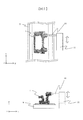
- FIG. 2 is an enlarged view of a hitting inspection unit 10 in FIG. 1. It is the outline
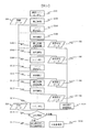
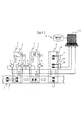
- FIG. 1 is an outline of a production line system for carrying out the inspection of this embodiment.
- FIG. 2 is a block diagram of the inspection apparatus.
- the conveyance path 2 conveys the structure 1 to be inspected from the production line, and pays out after performing the inspection.
- the first measuring machine 3 images the surface to be inspected.
- the first grip 4 grips the measurement target and can rotate in a direction perpendicular to the axis.
- the 1st scanning part 5 scans the 1st holding part 4 so that a measuring object may be extracted from the conveyance path 2, and a measuring object may be returned.
- the second measuring device 6 images the surface to be inspected under measurement conditions different from those of the first measuring device 3.
- the second gripping part 7 grips the measurement target with an axis different from that of the first gripping part 4 and can rotate in the orthogonal direction.
- the second scanning unit 8 scans the second gripping unit 7 so as to extract the measurement target from the transport path 2 and return the measurement target.
- the third scanning unit 9 extracts the measurement object from the conveyance path 2 and scans the structure 1 at the hitting position of the hitting test unit 22 shown in FIG.
- the hammering inspection apparatus 10 includes a hammering unit 11 that strikes a designated position of the structure 1.
- the surface measurement data obtained from the first measuring machine 3 and the second measuring machine 6 and the sound inspection data obtained from the sound inspection apparatus 10 are stored in a data storage / analysis process and Input to the display device 12.
- the design shape data input unit 14 shown in FIG. 2 reads design information and the like from the design shape data 13 shown in FIG.
- the setting unit 15 sets a striking reference position for determining a striking position for striking the structure 1 to be inspected from the design information.
- the first surface measurement unit 16 operates the first measuring machine 3, the first gripping unit 4, and the first scanning unit 5, and acquires the measurement data of the surface of the structure 1.
- the first data storage unit 17 stores the obtained measurement data.
- the second surface measurement unit 18 operates the second measuring device 6, the second gripping unit 7, and the second scanning unit 8 to acquire measurement data on the surface of the structure 1.
- the second data storage unit 19 stores the obtained measurement data.
- the determining unit 20 compares the measurement data obtained by the first surface measuring unit 16 and the second surface measuring unit 18 with the design shape data 13 to determine the hitting position in the hammering inspection apparatus 10.
- the control unit 21 sets the structure 1 and the sound inspection device 10 at the hitting position obtained by the determination unit 20.
- the hammering inspection unit 22 strikes the structure 1 in the set arrangement.
- the third data storage unit 23 stores the result obtained by the hammering test.
- the determination result processing unit 24 calculates an inspection result from the obtained surface measurement data and hammering inspection data.
- the display unit 25 displays the result of the determination result processing unit 24.
- the fourth data storage unit 26 stores the processing result.
- the determination unit 20, the control unit 21, and the measurement result processing unit 24 are included in the data storage / analysis process and the display device 12.
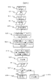
- FIG. 3 is a block diagram of an inspection process for one inspection object including the inspection method of this embodiment.
- the structure 1 being transported along the transport path 2 is extracted from the transport line by driving the first scanning unit 5 and the first gripping unit 4.
- the operations of the first scanning unit 5 and the first gripping unit 4 at this time are defined by the input of control data 104.
- the shape of the surface of the structure 1 is measured using the first measuring device 3 while the first scanning unit 5 and the first gripping unit 4 are being driven.
- the measurement result is sent as shape measurement data 106 to the shape measurement result calculation step in S115.
- the structure 1 that has finished the shape measurement step S105 is subjected to measurement object posture conversion in S107.
- the surface shape of the structure 1 is measured by the first measuring device 3 while the first scanning unit 5 and the first gripping unit 4 are being driven.
- the measured shape measurement data 106 is sent to the shape measurement result calculation step in S115.
- the structure 1 is returned to the transport path 2 by driving the first scanning unit 5 and the first gripping unit 4.
- the shape of the surface of the structure 1 is measured using the second measuring device 6 while the second scanning unit 8 and the second gripping unit 7 are being driven.
- the measurement result is sent as shape measurement data 106 to the shape measurement result calculation step in S115.
- the structure 1 that has finished the shape measurement step S111 is subjected to measurement object orientation conversion in S112.
- the surface shape of the structure 1 is measured by the second measuring device 6 while the second scanning unit 8 and the second gripping unit 7 are being driven.
- the measured shape measurement data 106 is sent to the shape measurement result calculation step in S115.
- the surface shape measurement result of the structure 1 is calculated from the shape measurement data 106 sent from each step, and the process proceeds to the shape determination step in S116.
- the shape data 119 (included in the design shape data 13 shown in FIG. 1) of the structure 1 is compared with the surface shape measurement result in S115, and the pass / fail of the shape is determined.
- FIG. 4 is a block diagram of a process for calculating the control data 104 in the block diagram of FIG.
- the design data 121 (included in the design shape data 13 shown in FIG. 1) stored in the design shape data input unit 14 is taken out.
- the contents of the design data 121 include, for example, shape data and a solid number to be inspected such as CAD information and model number information described in product design information.
- the retrieved design data 121 is read into the setting unit 15 in the design data reading step of S123.
- S126 it is determined whether or not there is a blind spot area other than the measurement area on the surface to be inspected. If it is determined that there is no blind spot area, the process proceeds to S129, and each measuring machine, each gripper, Measurement conditions for each scanning unit are determined. If it is determined that there is a blind spot area, the flow proceeds to S126, and it is determined whether the blind spot area is minimum. If it is determined that the blind spot area is the minimum, the process proceeds to S129, and the measurement conditions of each measuring machine, each gripping unit, and each scanning unit are determined. If it is determined that the blind spot area is not the minimum, the measurement condition is changed in S128, and the process returns to the measurement area calculation step in S125.
- FIG. 5 is a block diagram of a process for performing a hammering test in the hammering test unit 22 in the system configuration diagram of FIG.
- the design data 121 stored in the design shape data input unit 14 is taken out.
- the design data 121 includes information on the design dimensions of the striking position of the striking unit 11 by the sound striking device 10 with respect to the structure 1.
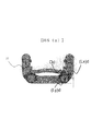
- FIG. 6A shows an example of the hitting position information.
- the distance (Lx) d from the side surface in the X direction in the drawing and the distance (Ly) d from the side surface in the Y direction in the drawing are , It is included in the design data 121 as hitting position information.
- a plurality of hitting position information is included in the design data 121 according to the three-dimensional feature amount of each part of the structure 1.
- the retrieved design data 121 is read into the setting unit 15 in the design data reading step of S131.
- the feature amount of the hitting position of the hitting unit 11 by the hitting device 10 is calculated from the read surface shape measurement data 106.
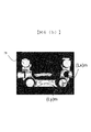
- FIG. 6B shows an example in which the hitting position information is calculated from the surface shape measurement data 106.
- the distance (Lx) m from the side and the distance (Ly) m from the side surface in the Y direction in the figure are calculated from the measurement data.
- (Lx) d and (L) indicate the hitting position Od in the design data 121 corresponding to (Lx) m and (Ly) m indicating the hitting position Om of the sounding device 10 calculated from the surface shape measurement data 106. Ly) A difference amount of d is calculated.
- the hitting position of the hitting unit 11 by the hitting device 10 is set to the center position Om of the cylindrical portion of the structure 1 by moving the hitting device 10 or the structure 1. .
- the hitting unit 11 is operated to measure the hitting sound in S136.
- the hitting result is determined in S137. If it is unsuccessful, it is carried out as a defective product in S139, and if it is acceptable, the inspection completion is paid out in S138.
- FIG. 7 shows an enlarged view of the hammering inspection unit 10 in FIG.
- the moving direction of the sounding device 10 or the structure 1 when the sounding device 10 of S135 shown in the flow of FIG. showed that.
- the hitting device 10 or the structure 1 is moved a plurality of times and set to predetermined hitting positions, and hitting is performed at each position to perform a hitting test. (Example 2)
- FIG. 8 shows an embodiment of a mass production casting inspection method and apparatus according to the present invention.
- a process for positioning by two positions of the structure 1 is added to the positioning process when performing the hammering inspection.
- the positioning device 29 is provided in front of the hammering inspection device 11 of FIG.
- the hitting position setting jig 30 sets the hitting position using the processing flow shown in FIG. 5 for a plurality of positions indicating the shape characteristics of the structure 1. Thereby, the positioning accuracy is improved and the determination accuracy in the hitting test is improved.
- the present invention provides a method for efficiently constructing a defect inspection method for a mass-produced cast product having a three-dimensional complex shape by using the mass-produced cast product inspection method and apparatus of the present invention, and further, a mass-produced cast product that replaces the current visual inspection In-line surface inspection device can be provided at the time of manufacturing, and it is possible to prevent oversight and determination mistakes during conventional visual inspection, and to manufacture a mass-produced cast product with high efficiency, high quality and high reliability. At the same time, it is possible to inspect all internal defects, cracks, and material defects in-line by hitting the whole number.
- hammering inspection part 23 ... first 3 data storage unit, 24 ... measurement result processing unit, 25 ... display unit, 26 ... fourth data storage unit, 27 ... one example of design shape data, 28 ... measurement shape data 1 example 29 ... hammering positioning device, 30 ... hammering positioning jig, S101 ... manufacturing line dispensing step, S102 ... inspection start step, S103 ... line extraction step, 104 ... control data, S105 ... shape measurement step, 106 ... shape measurement data, S107 ... measurement object posture conversion step, S108 ... shape measurement step, S109 ... line return step, S110 ... line extraction step, S111 ... Shape measurement step, S112 ... Measurement object posture conversion step, S113 ...
- Shape measurement step S114 ... Line return step, S115 ... Shape measurement result calculation step, S116 ... Shape pass / fail Judgment step, S117 ... Surface inspection end step, S118 ... Defect Unloading step, 119 ... shape data, S120 ... design data fetching step, 121 ... design data, S123 ... design data reading step, S124 ... measurement condition setting step, S125 ... measurement area Calculation step, S126 ... blind spot area presence / absence determination step, S127 ... blind spot area range determination step, S128 ... measurement condition change step, S129 ... measurement condition determination step, S130 ... design data extraction step, S131 ... Design data reading step, S132 ... Surface shape measurement data reading, S133 ...
- Striking position and feature size calculation step from surface shape measurement data S134 ... Measurement data and design data Difference amount calculation step, S135... Attachment position resetting step, S136 ... hammering sound measurement step, 122 ... hammering sound measurement data, S137 ... hammering sound determination step, S138 ... inspection end, payout step
Landscapes
- Physics & Mathematics (AREA)
- General Physics & Mathematics (AREA)
- Biochemistry (AREA)
- Life Sciences & Earth Sciences (AREA)
- Chemical & Material Sciences (AREA)
- Analytical Chemistry (AREA)
- Health & Medical Sciences (AREA)
- General Health & Medical Sciences (AREA)
- Immunology (AREA)
- Pathology (AREA)
- Acoustics & Sound (AREA)
- Length Measuring Devices By Optical Means (AREA)
- Length Measuring Devices With Unspecified Measuring Means (AREA)
- Measurement Of Mechanical Vibrations Or Ultrasonic Waves (AREA)
- Investigating Or Analyzing Materials By The Use Of Ultrasonic Waves (AREA)
Abstract
検査装置は、検査対象物の表面を計測する表面計測部と、検査対象物を打音検査する打音検査部と、表面計測部からの計測情報に基づいて、打音検査部の打付け部材の基準位置と検査対象物の設置基準位置との相対的位置を変更する。
Description
本発明は、鋳物部品の製造時インラインでの欠陥の検査装置および検査方法に関する。
自動車部品などの量産鋳造品では、鋳造プロセス終了時に鋳造欠陥の有無を判定し、鋳造欠陥の無い鋳造品を次の機械加工プロセスに提供する必要がある。
一般的に鋳造プロセスでは、種々の要因により鋳造欠陥が発生する。特に湯境により発生する表面欠陥は、当該物に外部荷重が加わる環境下では、疲労亀裂の起点になる可能性があり、鋳造プロセス終了時にはこの湯境による表面欠陥の有無を確認する事が重要である。また、表面欠陥以外に内部の鋳造欠陥や亀裂、材質不良の状態を非破壊で評価する必要性も高い。
従来、量産鋳造品工場では、上述の湯境による表面欠陥の有無や表面に現れる介在物の有無、型落ちによる欠損、打痕の有無、等を判定するために目視検査が実施されている。一方、鋳造品の生産量が増加し生産速度も速くなると、目視検査での対応が難しくなる。そのため、目視検査に代わる自動欠陥検査技術が求められている。
また、一般的な量産品の表面検査では、電子基盤など平面的な対象物に対するインライン自動検査技術が発達しているが、自動車部品用の鋳造品にみられるような3次元的に複雑な立体構造物の全表面状態の自動検査技術は多くは見られていない。
また、表面欠陥以外の内部の鋳造欠陥や亀裂、材質不良の状態は、従来、製造ラインでの抜き取りによる破壊検査により対応している。
特許文献1には、複数の3次元形状計測法、表面計測法を相補的に組み合わせる事で測定対象の形状によらず高い計測精度を確保した3次元形状検査方法および装置が記載されている。この特許文献1では、対象物が回転軸中心を持つ羽根車のような3次元的には形状変化が比較的小さい構造物には有効であるが、本特許で対象とする自動車部品などの量産鋳造品のような3次元的に形状変化が大きい複雑構造物の全表面を検査するには不十分である。
また、特許文献2には、トンネルのような固定構造物の内部材料劣化を検出するための打音検査システムが記載されている。特許文献2では、トンネル内の障害物を回避するためステレオカメラでトンネル内部を計測しながら打音検査を実施しているが、製造ラインの量差鋳造品においては複雑な3次元形状のため上記のシステムでは不十分である。
また、量産鋳造品の製造時のインラインでの表面検査では、連続的に短時間で大量の鋳造品が生産されるため、目視にかわる自動表面検査では、1個あたりの検査時間を極力、短くする必要がある。3次元複雑形状物に対する打音検査では、検査対象物の打ち付け位置により発生する音響特性が変化するため、3次元形状の特定位置を正確に打ち付ける必要がある。一方、鋳造品は、鋳造時に用いる砂型や中子の寸法および設置精度が、機械加工品より劣るため、個々の鋳造品において設計寸法との差が発生し、3次元形状の特定位置を正確に打ち付けるには、個々の対象物の3次元形状を把握する必要がある。
そのため、本発明の課題は、上記のような事情を背景になされたものであり、3次元複雑形状をした量産鋳造品の表面欠陥および内部欠陥や材質不良を、非破壊での表面欠陥検査と打音による内部状況欠陥評価により、精度よく効率的に検査する方法および装置を提供することにある。
本発明の第1の態様によると、検査装置は、検査対象物の表面を計測する表面計測部と、検査対象物を打音検査する打音検査部と、表面計測部からの計測情報に基づいて、打音検査部の打付け部材の基準位置と検査対象物の設置基準位置との相対的位置を変更する。
本発明の第2の態様によると、検査方法は、検査対象物の表面を計測し、表面計測データからの計測情報に基づいて、打音検査部の打付け部材の基準位置と検査対象物の設置基準位置との相対的位置を変更する。
本発明の第3の態様によると、検査装置は、検査対象となる対象物を打ち付ける打付位置を決めるための打付基準位置を予め設定する設定部と、対象物の表面を計測する表面計測部と、対象物を打音検査する打音検査部と、打付基準位置と表面計測部からの計測情報に基づいて、対象物を打ち付ける打付位置を決定する決定部と、を備える。
本発明の第2の態様によると、検査方法は、検査対象物の表面を計測し、表面計測データからの計測情報に基づいて、打音検査部の打付け部材の基準位置と検査対象物の設置基準位置との相対的位置を変更する。
本発明の第3の態様によると、検査装置は、検査対象となる対象物を打ち付ける打付位置を決めるための打付基準位置を予め設定する設定部と、対象物の表面を計測する表面計測部と、対象物を打音検査する打音検査部と、打付基準位置と表面計測部からの計測情報に基づいて、対象物を打ち付ける打付位置を決定する決定部と、を備える。
従来の目視検査時における見落としや判定ミスを防止すると同時に、抜き取りでの対応であった内部欠陥や亀裂、材質不良を全数実施により抜けがなく検知でき、高効率で高品質な信頼性が高い量産鋳造品の製造を実現することができる。
以下、本発明の実施例を、図面を用いて説明する。
(実施例1)
(実施例1)
図1は、本実施例の検査を実施するための製造ラインシステムの概要である。図2は、検査装置のブロック構成図である。
搬送路2は、検査対象である構造物1を製造ラインから搬送し、検査実施後、払い出しを行う。
第1測定機3は、検査対象の表面を撮像する。第1把持部4は、測定対象を把持し、かつ軸と直交する方向に回転可能である。第1走査部5は、搬送路2から測定対象を抜き出し、かつ測定対象を戻すように第1把持部4を走査する。
第2測定機6は、第1測定機3と異なる測定条件で検査対象の表面を撮像する。
第2把持部7は、第1把持部4と異なる軸で測定対象を把持し、直交方向に回転可能である。第2走査部8は、搬送路2から測定対象を抜き出し、かつ測定対象を戻すように第2把持部7を走査する。
第3走査部9は、搬送路2から測定対象を抜き出し、図2に示される打音検査部22の打音打付け位置に構造物1を走査する。打音検査装置10は、構造物1の指定位置を打ち付ける打付け部11を有する。
図1に示す製造ラインシステムにおいて、第1測定機3、第2測定機6から得られた表面計測データ、および打音検査装置10から得られた打音検査データは、データ記憶・分析処理および表示装置12へ入力される。
図2に示される設計形状データ入力部14は、図1に示される設計形状データ13から設計情報等を読み込む。設定部15は、この設計情報から検査対象となる構造物1を打ち付ける打付け位置を決めるための打付け基準位置を設定する。
第1表面計測部16は、第1測定機3、第1把持部4、第1走査部5を動作させ、構造物1の表面の計測データを取得する。第1データ記憶部17は、得られた計測データを記憶する。
第2表面計測部18は、第2測定機6、第2把持部7、第2走査部8を動作させ、構造物1の表面の計測データを取得する。第2データ記憶部19は、得られた計測データを記憶する。
決定部20は、第1表面計測部16と第2表面計測部18で得られた計測データと設計形状データ13とを比較して、打音検査装置10における打付け位置を決定する。制御部21は、決定部20で得られた打付け位置に構造物1および打音検査装置10を設定する。打音検査部22は、設定された配置において構造物1に打付けを実施する。
第3データ記憶部23は、打音検査により得られた結果を記憶する。判定結果処理部24は、得られた表面計測データおよび打音検査データから検査結果を算出する。
表示部25は、判定結果処理部24での結果を表示する。第4データ記憶部26は、処理結果を記憶する。
また、設定部15、第1表面計測部16、第2表面計測部18およびこれらの計測で得られた計測データの第1データ記憶部17と第2データ記憶部19と第3データ記憶部23、決定部20、制御部21、測定結果処理部24は、データ記憶・分析処理および表示装置12に含まれる。
図3は、本実施例の検査方法を含む、1個の被検査物に対する検査プロセスのブロック図である。
S101において、検査開始前に製造ラインから構造物1が払い出しされると、S102において、検査が開始される。
S103において、搬送路2を搬送中の構造物1を、第1走査部5と第1把持部4の駆動により搬送ラインから抜き出す。このときの第1走査部5と第1把持部4の動作は、制御データ104の入力によって定義される。
次に、S105において、第1走査部5と第1把持部4の駆動中に、第1測定機3を用いて構造物1の表面の形状を測定する。測定した結果は、形状測定データ106として、S115の形状測定結果算出ステップに送られる。
形状測定ステップS105を終えた構造物1は、S107において測定対象姿勢変換が実施される。
その後、S108において、第1走査部5と第1把持部4の駆動中に、構造物1の表面形状測定を第1測定機3により実施する。測定した形状測定データ106は、S115の形状測定結果算出ステップに送られる。
S109において、第1走査部5と第1把持部4の駆動により、構造物1を搬送路2に戻す。
次に、S110において、搬送路2を搬送中の構造物1を、第2走査部8と第2把持部7の駆動により搬送ラインから抜き出す。このときの第2走査部8と第2把持部7の動作は、制御データ104の入力によって定義される。
S111において、第2走査部8と第2把持部7の駆動中に、第2測定機6を用いて構造物1の表面の形状を測定する。測定した結果は、形状測定データ106として、S115の形状測定結果算出ステップに送られる。
形状測定ステップS111を終えた構造物1は、S112において測定対象姿勢変換が実施される。
その後、S113において、第2走査部8と第2把持部7の駆動中に、構造物1の表面形状測定を第2測定機6により実施する。測定した形状測定データ106は、S115の形状測定結果算出ステップに送られる。
S114において、第2走査部8と第2把持部7の駆動により、構造物1を搬送路2に戻す。
S114と前後して、S115においては、各ステップより送られた形状測定データ106から、構造物1の表面形状測定結果を算出し、S116の形状判定ステップへと進む。
S116の形状判定ステップでは、構造物1の形状データ119(図1に示される設計形状データ13に含まれる)とS115における表面形状測定結果とを比較し、形状合否が判断される。
合格と判断される場合にはS117の表面検査を終了し、打音検査のステップへ進み、不合格と判断される場合にはS118の不良品搬出ステップに進む。
図4は、図3のブロック図における、制御データ104を算出するプロセスのブロック図である。
S120において、設計形状データ入力部14に格納された設計データ121(図1に示される設計形状データ13に含まれる)を取り出す。設計データ121の内容としては、例えば、製品設計情報に記載されたCAD情報、型番情報など、検査対象の形状データと固体番号を含むものとする。
取り出された設計データ121は、S123の設計データ読み込みステップにおいて設定部15に読み込まれる。
S124において、各測定機、各把持部および各走査部の測定条件が設定され、S125において検査対象の測定領域が算出される。
S126において、検査対象の表面のうち測定領域以外の死角領域となっている領域の有無が判定され、死角領域がないと判定された場合には、S129に進み、各測定機、各把持部および各走査部の測定条件が決定される。死角領域があると判定された場合には、フローはS126に進み、死角領域が最小となっているか判定される。死角領域が最小であると判定された場合には、S129に進み、各測定機、各把持部および各走査部の測定条件が決定される。死角領域が最小でないと判定された場合には、S128において測定条件の変更が実施され、S125の測定領域算出ステップに戻る。
以上のステップを、S126で死角領域がないと判定される、または、S127で死角領域が最小であると判定されるまで繰り返し、S129の測定条件決定ステップまで進む。決定した各測定機、各把持部および各走査部の測定条件は、制御データ104として第2データ記憶部19に格納され、図3の各ステップにおいてデータ記憶部から読み出され、制御部21を通して各測定機、各把持部および各走査部の動作を制御する。
図5は、図1のシステム構成図の打音検査部22で打音検査を実施するプロセスのブロック図である。
S130において、設計形状データ入力部14に格納された設計データ121を取り出す。設計データ121の内容には前述の内容に加えて、構造物1に対して、打音装置10による打付け部11の打付け位置の設計寸法上の情報も含んでいる。
図6(a)には、打付け位置情報の例を示した。構造物1の一部の円筒部分の中心位置Odを打付け位置と示すために、図中X方向の側面からの距離(Lx)dおよび図中Y方向の側面からの距離(Ly)dが、設計データ121の中に打付け位置情報として含まれる。他にも構造物1の各部位の3次元特徴量により複数の打付け位置情報が設計データ121に含まれる。
取り出された設計データ121は、S131の設計データ読み込みステップにおいて設定部15に読み込まれる。
次に、S132において、図2の第1表面計測部16および第2表面計測部18で得られ、第1データ記憶部17と第2データ記憶部19に記憶されている表面形状計測データ106を取り出す。
S133において、読み込んだ表面形状計測データ106から、打音装置10による打付け部11の打付け位置の特徴量を算出する。
図6(b)には、表面形状計測データ106から打付け位置情報を算出した例を示した。図6(a)の設計情報で設定した構造物1の一部の円筒部分の中心位置Odに相当する計測データ上で対応する円筒部分の中心位置Omを示すために、図中X方向の側面からの距離(Lx)mおよび図中Y方向の側面からの距離(Ly)mを、計測データから算出する。
S134において、表面形状計測データ106から算出した打音装置10の打付け位置Omを示す(Lx)mおよび(Ly)mと対応する設計データ121における打付け位置Odを示す(Lx)dおよび(Ly)dの差分量をそれぞれ算出する。
得られた差分量を基に、S135において打音装置10による打付け部11の打付け位置を、打音装置10または構造物1を移動させ構造物1の円筒部分の中心位置Omに設定する。
位置設定が終了すると、S136において、打付け部11を動作させ打音計測を実施する。
得られた打音計測データ122を基にS137において打音結果の判定を実施し、不合格の場合はS139で不良品として搬出し、合格の場合はS138で検査終了払い出しを行う。
図7には図1における打音検査部10の拡大図を示した。図5のフローで示したS135の打音装置10による打付け部11の打付け位置および、構造物1の円筒部分の中心位置Omに設定する場合の打音装置10または構造物1の移動方向を示した。打付け位置が複数設定される場合は、打音装置10または構造物1を複数回移動させ所定の打付け位置に設定し、各位置で打付けし打音検査を実施する。
(実施例2)
(実施例2)
本発明による量産鋳造品の検査方法および装置の実施例を図8に示した。本実施例では、実施例1の構成に加えて、打音検査を実施する際の位置決めプロセスに、構造物1の2点の位置により位置決めをするプロセスを追加する。
すなわち、図8の打音検査装置11の手前に位置決め装置29を設ける。位置決め装置29では打付け位置設定用冶具30により構造物1の形状特徴を示す複数の位置に対して図5に示した処理フローを用いて、打付け位置を設定する。それにより位置決め精度が向上し打音検査における判定精度が向上する。
本発明の量産鋳造品の検査方法および装置を用いることで、3次元複雑形状をした量産鋳造品の欠陥検査方法を効率的に構築する方法を提供し、さらに現状の目視検査に代わる量産鋳造品の製造時のインライン表面検査装置を提供でき、従来の目視検査時における見落としや判定ミスを防止し高効率で高品質な信頼性が高い量産鋳造品の製造が実現できる。同時に、全数を打音検査する事により内部欠陥や亀裂、材質不良検査をインラインで全数検査する事が可能となる。
次の優先権基礎出願の開示内容は引用文としてここに組み込まれる。
日本国特許出願2016年第57817号(2016年3月23日出願)
日本国特許出願2016年第57817号(2016年3月23日出願)
1・・・構造物、2・・・搬送路、3・・・第1測定機、4・・・第1把持部、5・・・第1走査部、6・・・第2測定機、7・・・第2把持部、8・・・第2走査部、9・・・第3捜査部、10・・・打音検査装置、11・・・打付け部、12・・・データ記憶、分析処理および表示装置、13・・・設計形状データ、14・・・設計形状データ入力部、15・・・設定部、16・・・第1表面計測部、17・・・第1データ記憶部、18・・・第2表面計測部、19・・・第2データ記憶部、20・・・決定部、21・・・制御部、22・・・打音検査部、23・・・第3データ記憶部、24・・・測定結果処理部、25・・・表示部、26・・・第4データ記憶部、27・・・設計形状データの1例、28・・・計測形状データの1例、29・・・打音位置決め装置、30・・・打音位置決め冶具、S101・・・製造ライン払い出しステップ、S102・・・検査開始ステップ、S103・・・ライン抜き出しステップ、104・・・制御データ、S105・・・形状測定ステップ、106・・・形状測定データ、S107・・・測定対象姿勢変換ステップ、S108・・・形状測定ステップ、S109・・・ライン戻しステップ、S110・・・ライン抜き出しステップ、S111・・・形状測定ステップ、S112・・・測定対象姿勢変換ステップ、S113・・・形状測定ステップ、S114・・・ライン戻しステップ
、S115・・・形状測定結果算出ステップ、S116・・・形状合否判定ステップ、S117・・・表面検査終了ステップ、S118・・・不良品搬出ステップ、119・・・形状データ、S120・・・設計データ取り出しステップ、121・・・設計データ、S123・・・設計データ読み込みステップ、S124・・・測定条件設定ステップ、S125・・・測定領域算出ステップ、S126・・・死角領域有無判定ステップ、S127・・・死角領域範囲判定ステップ、S128・・・測定条件変更ステップ、S129・・・測定条件決定ステップ、S130・・・設計データ取り出しステップ、S131・・・設計データ読み込みステップ、S132・・・表面形状測定データ読み込み、S133・・・表面形状測定データから打音の打付け位置および特徴寸法算出ステップ、S134・・・測定データと設計データとの差分量計算ステップ、S135・・・差分量に基づく打付け位置再設定ステップ、S136・・・打音計測ステップ、122・・・打音計測データ、S137・・・打音結果判定ステップ、S138・・・検査終了、払い出しステップ
、S115・・・形状測定結果算出ステップ、S116・・・形状合否判定ステップ、S117・・・表面検査終了ステップ、S118・・・不良品搬出ステップ、119・・・形状データ、S120・・・設計データ取り出しステップ、121・・・設計データ、S123・・・設計データ読み込みステップ、S124・・・測定条件設定ステップ、S125・・・測定領域算出ステップ、S126・・・死角領域有無判定ステップ、S127・・・死角領域範囲判定ステップ、S128・・・測定条件変更ステップ、S129・・・測定条件決定ステップ、S130・・・設計データ取り出しステップ、S131・・・設計データ読み込みステップ、S132・・・表面形状測定データ読み込み、S133・・・表面形状測定データから打音の打付け位置および特徴寸法算出ステップ、S134・・・測定データと設計データとの差分量計算ステップ、S135・・・差分量に基づく打付け位置再設定ステップ、S136・・・打音計測ステップ、122・・・打音計測データ、S137・・・打音結果判定ステップ、S138・・・検査終了、払い出しステップ
Claims (9)
- 検査対象物の表面を計測する表面計測部と、
前記検査対象物を打音検査する打音検査部と、
前記表面計測部からの計測情報に基づいて、前記打音検査部の打付け部材の基準位置と前記検査対象物の設置基準位置との相対的位置を変更する検査装置。 - 請求項1に記載された検査装置であって、
前記表面計測部および打音検査部で得られた計測データを基に前記検査対象物の計測結果が判定基準を満足するか否かを判定する測定結果処理部を有する検査装置。 - 請求項2に記載された検査装置であって、
前記検査対象物の基準形状が予め設定され、
前記基準形状と前記計測データとの差分量に基づいて、前記打付け位置を決定する検査装置。 - 検査対象物の表面を計測し、
前記表面の計測データからの計測情報に基づいて、打音検査部の打付け部材の基準位置と前記検査対象物の設置基準位置との相対的位置を変更する検査方法。 - 請求項4に記載された検査方法であって、
前記表面の計測データおよび打音検査データを基に前記検査対象物の計測結果が判定基準を満足するか否かを判定する検査方法。 - 請求項4または5に記載された検査方法であって、
前記検査対象物の基準形状が予め設定され、
前記基準形状と前記計測データとの差分量に基づいて、前記打付け位置を決定する検査方法。 - 検査対象となる対象物を打ち付ける打付位置を決めるための打付基準位置を予め設定する設定部と、
前記対象物の表面を計測する表面計測部と、
前記対象物を打音検査する打音検査部と、
前記打付基準位置と前記表面計測部からの計測情報に基づいて、前記対象物を打ち付ける打付位置を決定する決定部と、を備える検査装置。 - 請求項7に記載された検査装置であって、
前記設定部は、更に、前記対象物の基準形状を予め設定し、
前記決定部は、前記基準形状と前記計測情報との差分量に基づいて、前記打付位置を決定する検査装置。 - 請求項7に記載された検査装置であって、
前記設定部は、更に、差分量を計算するための差分基準位置を予め設定し、
前記決定部は、前記差分基準位置と前記計測情報との差分量に基づいて、前記打付位置を決定する検査装置。
Applications Claiming Priority (2)
| Application Number | Priority Date | Filing Date | Title |
|---|---|---|---|
| JP2016057817A JP6602707B2 (ja) | 2016-03-23 | 2016-03-23 | 検査装置及び検査方法 |
| JP2016-057817 | 2016-03-23 |
Publications (1)
| Publication Number | Publication Date |
|---|---|
| WO2017163476A1 true WO2017163476A1 (ja) | 2017-09-28 |
Family
ID=59901002
Family Applications (1)
| Application Number | Title | Priority Date | Filing Date |
|---|---|---|---|
| PCT/JP2016/082329 Ceased WO2017163476A1 (ja) | 2016-03-23 | 2016-10-31 | 検査装置及び検査方法 |
Country Status (2)
| Country | Link |
|---|---|
| JP (1) | JP6602707B2 (ja) |
| WO (1) | WO2017163476A1 (ja) |
Cited By (1)
| Publication number | Priority date | Publication date | Assignee | Title |
|---|---|---|---|---|
| US12140415B2 (en) | 2018-02-27 | 2024-11-12 | Nikon Corporation | Image analysis device, analyis device, shape measurement device, image analysis method, measurement condition determination method, shape measurement method, and program |
Citations (4)
| Publication number | Priority date | Publication date | Assignee | Title |
|---|---|---|---|---|
| JPH01227958A (ja) * | 1988-03-09 | 1989-09-12 | Maki Seisakusho:Kk | 青果物の内部品質検査装置 |
| JPH0392758A (ja) * | 1989-09-05 | 1991-04-17 | Akebono Brake Res & Dev Center Ltd | 製品検査方法 |
| JP2005300363A (ja) * | 2004-04-12 | 2005-10-27 | Toshiba Corp | 超音波探傷システムおよび超音波探傷試験方法 |
| JP2013134090A (ja) * | 2011-12-26 | 2013-07-08 | Central Nippon Expressway Co Ltd | フィンガージョイントの破損判定方法 |
Family Cites Families (2)
| Publication number | Priority date | Publication date | Assignee | Title |
|---|---|---|---|---|
| FR2669420B1 (fr) * | 1990-11-21 | 1993-01-15 | Hispano Suiza Sa | Procede de controle de mesures dimensionnelles de pieces de fonderie. |
| US20090287450A1 (en) * | 2008-05-16 | 2009-11-19 | Lockheed Martin Corporation | Vision system for scan planning of ultrasonic inspection |
-
2016
- 2016-03-23 JP JP2016057817A patent/JP6602707B2/ja active Active
- 2016-10-31 WO PCT/JP2016/082329 patent/WO2017163476A1/ja not_active Ceased
Patent Citations (4)
| Publication number | Priority date | Publication date | Assignee | Title |
|---|---|---|---|---|
| JPH01227958A (ja) * | 1988-03-09 | 1989-09-12 | Maki Seisakusho:Kk | 青果物の内部品質検査装置 |
| JPH0392758A (ja) * | 1989-09-05 | 1991-04-17 | Akebono Brake Res & Dev Center Ltd | 製品検査方法 |
| JP2005300363A (ja) * | 2004-04-12 | 2005-10-27 | Toshiba Corp | 超音波探傷システムおよび超音波探傷試験方法 |
| JP2013134090A (ja) * | 2011-12-26 | 2013-07-08 | Central Nippon Expressway Co Ltd | フィンガージョイントの破損判定方法 |
Cited By (1)
| Publication number | Priority date | Publication date | Assignee | Title |
|---|---|---|---|---|
| US12140415B2 (en) | 2018-02-27 | 2024-11-12 | Nikon Corporation | Image analysis device, analyis device, shape measurement device, image analysis method, measurement condition determination method, shape measurement method, and program |
Also Published As
| Publication number | Publication date |
|---|---|
| JP2017173063A (ja) | 2017-09-28 |
| JP6602707B2 (ja) | 2019-11-06 |
Similar Documents
| Publication | Publication Date | Title |
|---|---|---|
| JP6560220B2 (ja) | 表面欠陥の検出のための検査システムを点検する方法及び装置 | |
| JP6451843B2 (ja) | クランクシャフトの検査方法及び装置 | |
| US11410298B2 (en) | System and method for determining part damage | |
| CN111156923A (zh) | 工件检测方法、装置、计算机设备以及存储介质 | |
| CN102077052B (zh) | 用于超声波检查的扫描计划的视觉系统 | |
| US8490492B2 (en) | Method for nondestructive testing of pipes | |
| US8345094B2 (en) | System and method for inspecting the interior surface of a pipeline | |
| JP6633454B2 (ja) | 変状部の検出方法 | |
| EP3431920A1 (en) | Device, system, and method for inspecting crankshaft shape | |
| JP2020016667A (ja) | 変状部の検査装置 | |
| JP2019196985A (ja) | 検査装置及び検査方法 | |
| JP6602707B2 (ja) | 検査装置及び検査方法 | |
| JP2010101721A (ja) | 成型ドラム上のタイヤ構成部材の検査方法及び装置 | |
| JP2006170684A (ja) | プレス不良の検査方法、及び検査装置 | |
| JP6650379B2 (ja) | 表面検査装置、表面検査方法及びデータベース | |
| JPH05298513A (ja) | プロセスパラメータの非許容偏差の検出方法 | |
| JP6884077B2 (ja) | 表面検査装置及び表面検査方法 | |
| JP2005283267A (ja) | 貫通穴計測装置及び方法並びに貫通穴計測用プログラム | |
| CN114646280A (zh) | 使用距离数据的结构不一致检测 | |
| KR101287924B1 (ko) | 결함 계측 시스템 및 그 방법 | |
| Świłło et al. | Automatic inspection of surface defects in die castings after machining | |
| JP5133651B2 (ja) | レーザ溶接評価方法 | |
| JP6135443B2 (ja) | 鋼片の検査・手入れ支援装置及び鋼片の検査・手入れ方法 | |
| JP6784802B2 (ja) | き裂検査装置およびき裂検査方法 | |
| JP6596221B2 (ja) | き裂検査装置およびき裂検査方法 |
Legal Events
| Date | Code | Title | Description |
|---|---|---|---|
| NENP | Non-entry into the national phase |
Ref country code: DE |
|
| 121 | Ep: the epo has been informed by wipo that ep was designated in this application |
Ref document number: 16895499 Country of ref document: EP Kind code of ref document: A1 |
|
| 122 | Ep: pct application non-entry in european phase |
Ref document number: 16895499 Country of ref document: EP Kind code of ref document: A1 |