WO2017163456A1 - 酸化剤濃度の測定方法及び測定装置、並びに電子材料洗浄装置 - Google Patents
酸化剤濃度の測定方法及び測定装置、並びに電子材料洗浄装置 Download PDFInfo
- Publication number
- WO2017163456A1 WO2017163456A1 PCT/JP2016/076829 JP2016076829W WO2017163456A1 WO 2017163456 A1 WO2017163456 A1 WO 2017163456A1 JP 2016076829 W JP2016076829 W JP 2016076829W WO 2017163456 A1 WO2017163456 A1 WO 2017163456A1
- Authority
- WO
- WIPO (PCT)
- Prior art keywords
- cleaning
- sulfuric acid
- oxidant concentration
- oxidant
- measuring
- Prior art date
- Legal status (The legal status is an assumption and is not a legal conclusion. Google has not performed a legal analysis and makes no representation as to the accuracy of the status listed.)
- Ceased
Links
Images



Classifications
-
- G—PHYSICS
- G01—MEASURING; TESTING
- G01N—INVESTIGATING OR ANALYSING MATERIALS BY DETERMINING THEIR CHEMICAL OR PHYSICAL PROPERTIES
- G01N21/00—Investigating or analysing materials by the use of optical means, i.e. using sub-millimetre waves, infrared, visible or ultraviolet light
- G01N21/75—Systems in which material is subjected to a chemical reaction, the progress or the result of the reaction being investigated
- G01N21/77—Systems in which material is subjected to a chemical reaction, the progress or the result of the reaction being investigated by observing the effect on a chemical indicator
-
- G—PHYSICS
- G01—MEASURING; TESTING
- G01N—INVESTIGATING OR ANALYSING MATERIALS BY DETERMINING THEIR CHEMICAL OR PHYSICAL PROPERTIES
- G01N21/00—Investigating or analysing materials by the use of optical means, i.e. using sub-millimetre waves, infrared, visible or ultraviolet light
- G01N21/75—Systems in which material is subjected to a chemical reaction, the progress or the result of the reaction being investigated
- G01N21/77—Systems in which material is subjected to a chemical reaction, the progress or the result of the reaction being investigated by observing the effect on a chemical indicator
- G01N21/78—Systems in which material is subjected to a chemical reaction, the progress or the result of the reaction being investigated by observing the effect on a chemical indicator producing a change of colour
-
- G—PHYSICS
- G01—MEASURING; TESTING
- G01N—INVESTIGATING OR ANALYSING MATERIALS BY DETERMINING THEIR CHEMICAL OR PHYSICAL PROPERTIES
- G01N31/00—Investigating or analysing non-biological materials by the use of the chemical methods specified in the subgroup; Apparatus specially adapted for such methods
Definitions
- the present invention relates to a method and apparatus for measuring an oxidant concentration in a sulfuric acid solution containing a metal and an oxidant.
- the present invention also relates to an electronic material cleaning apparatus using this apparatus.
- sulfuric acid-based oxidant solutions such as SPM (mixed solution of sulfuric acid and hydrogen peroxide solution), SOM (ozone blowing sulfuric acid), and electrolytic sulfuric acid are used for resist removal, metal etching, and the like.
- SPM mixed solution of sulfuric acid and hydrogen peroxide solution
- SOM ozone blowing sulfuric acid
- electrolytic sulfuric acid is used for resist removal, metal etching, and the like.
- resist removal and metal etching using a sulfuric acid-based oxidant solution the effect of the concentration of the oxidant in the sulfuric acid-based oxidant solution on the processing effect is large. For this reason, measurement and management of the oxidant concentration of the sulfuric acid-based oxidant solution are important requirements.
- a method for measuring the oxidant concentration in SPM or electrolytic sulfuric acid there are the following methods.
- the present invention can measure the oxidant concentration in a sulfuric acid solution containing a metal and an oxidant accurately and efficiently without being affected by impurities such as metal, and the oxidant concentration can be easily brought online. It is an object of the present invention to provide a measuring method, a measuring apparatus, and an electronic material cleaning apparatus using the measuring method and measuring apparatus.
- the present inventor can measure the absorbance after adding a potassium iodide solution to a sulfuric acid solution, and easily and accurately adjust the oxidant concentration in the sulfuric acid solution without being affected by impurities such as mixed metals. It was confirmed that it could be measured.
- the gist of the present invention is as follows.
- a method for measuring the oxidant concentration of a sulfuric acid solution containing a metal and an oxidant wherein a mixing step of mixing the sulfuric acid solution and a potassium iodide solution, and any of wavelengths of 200 to 600 nm of the obtained mixed solution
- a method for measuring an oxidant concentration comprising: an absorbance measurement step for measuring the absorbance, and a quantitative step for quantifying the oxidant concentration of the sulfuric acid solution based on the measurement result of the absorbance.
- the sulfuric acid solution is a semiconductor wafer cleaning liquid or a cleaning waste liquid used for cleaning the semiconductor wafer, and the cleaning liquid is supplied to the semiconductor wafer cleaning process.
- a part of the cleaning liquid or the cleaning waste liquid is separated from the feeding system or the cleaning drainage system for discharging the cleaning drainage from the semiconductor wafer cleaning process, and the oxidant concentration is measured online. Measuring method of oxidant concentration.
- An apparatus for measuring the oxidant concentration of a sulfuric acid solution containing a metal and an oxidant the mixing means for mixing the sulfuric acid solution and the potassium iodide solution, and any of wavelengths of 200 to 600 nm of the obtained mixed liquid
- An oxidant concentration measuring device comprising: an absorbance measuring unit that measures the absorbance; and a quantifying unit that quantifies the oxidant concentration of the sulfuric acid solution based on the measurement result of the absorbance.
- the sulfuric acid solution is a semiconductor wafer cleaning liquid or a cleaning waste liquid used for cleaning the semiconductor wafer, and the cleaning liquid is supplied to the semiconductor wafer cleaning process.
- An electronic material cleaning apparatus comprising: the oxidant concentration measuring unit according to any one of [4] to [6].
- the oxidant concentration in a sulfuric acid solution containing a metal and an oxidant such as a sulfuric acid-based oxidant solution mixed with a metal used in the cleaning process of the electronic material can be measured easily and stably with high accuracy without being affected by impurities such as metals. Also, continuous online monitoring can be performed easily.
- the sulfuric acid-based oxidizer solution such as SPM or electrolytic sulfuric acid and a metal or resist resulting from wafer cleaning is mixed, the sulfuric acid-based oxidizer solution is not affected by impurities such as metal.
- concentration of the oxidizing agent can be accurately measured.
- this measurement technique is used when cleaning waste liquid from a sulfuric acid-based oxidant solution is recovered and the oxidant in the sulfuric acid-based oxidant solution is regenerated and reused for cleaning.
- the oxidant concentration in the cleaning liquid can be accurately monitored, and efficient cleaning can be performed with the cleaning liquid having a predetermined oxidant concentration.
- a potassium iodide (KI) solution is added to a sulfuric acid solution containing a metal and an oxidizing agent, and an oxidizing agent (oxidizing substance) such as peroxodisulfuric acid in the sulfuric acid solution is selected as KI in the following reaction formula. Reaction to produce yellow color with free iodine (I 2 ).
- oxidizing substance such as peroxodisulfuric acid in the sulfuric acid solution
- concentration contains a metal and an oxidizing agent, and there is no restriction
- the present invention is used for cleaning a semiconductor wafer in which metal is exposed on at least a part of the surface, thereby measuring the oxidant concentration of a sulfuric acid oxidant solution such as electrolytic sulfuric acid, SPM, or SOM containing metal as an impurity. Useful.
- the present invention provides a cleaning process in the case of cleaning a semiconductor wafer using such a sulfuric acid-based oxidant solution as a cleaning liquid, recovering the cleaning waste liquid, regenerating the oxidant, and reusing it as a cleaning liquid. This is effective when the oxidant concentration in the cleaning liquid supplied to the cleaning liquid or the cleaning waste liquid discharged from the cleaning process is measured online to control the concentration.
- Examples of the potassium iodide solution include an aqueous potassium iodide solution of about 10 to 200 g / L from the viewpoint of handleability.
- the amount of potassium iodide solution added to the sulfuric acid solution to be measured is appropriately determined depending on the oxidant concentration in the sulfuric acid solution.
- the potassium iodide solution is added so that the amount of KI added is about 5 to 20 times (volume ratio) with respect to oxidizing substances such as peroxysulfuric acid, hydrogen peroxide, and ozone in the sulfuric acid solution to be measured. It is preferable.
- a sulfuric acid solution containing a metal and an oxidizing agent is diluted as necessary, and after adding and mixing a potassium iodide solution, the absorbance at a wavelength of 200 to 600 nm is measured.
- the measurement wavelength is preferably 200 to 500 nm, more preferably 250 to 400 nm.
- the absorbance can be measured using a commercially available absorptiometer.
- the measurement target liquid of the present invention has an oxidant concentration of about 0.001 to 1 mol / L as a measurement concentration. This measured concentration is the oxidant concentration of the sulfuric acid solution containing the metal and oxidant before dilution for measuring the oxidant concentration.
- Oxidant concentration 0.001-1 mol / L
- Oxidant concentration 0.01 to 10 mol / L
- Oxidant concentration 0.001-1 mol / L
- the measurement of the oxidant concentration according to the present invention can be performed by a batch method in which the dilution of the sulfuric acid solution to be measured and the potassium iodide solution are mixed in the mixing tank, and then the absorbance of the mixed solution is measured.
- a flow-type absorptiometer By using a flow-type absorptiometer, online mixing is facilitated by mixing these lines.
- pure water for dilution is introduced into the sample liquid introduction pipe 11 to the flow type absorptiometer 1 having the pump P 1 .
- the pipe 11 a sulfuric acid solution containing a metal and an oxidizing agent such as oxidizing agent containing sulfuric acid based cleaning fluid from the cleaning process of the semiconductor wafer are injected from the pipe 12 having a pump P 2, the oxidizing agent containing sulfuric acid based cleaning solution with pure water Diluted.
- Pipe 13 having a pump P 3 for injecting a potassium iodide solution is connected downstream of the injection point of the oxidizing agent containing sulfuric acid based cleaning solution.
- a potassium iodide solution is injected into the diluted oxidant-containing sulfuric acid-based cleaning solution from the pipe 13.
- the potassium iodide solution is prepared by injecting a high-concentration potassium iodide solution from the pipe 14 having the pump P 4 into the pipe 13 into which pure water is introduced, and diluting and adjusting the concentration.
- the liquid after the potassium iodide solution is injected is further mixed by the line mixer 2, and then the mixed liquid is introduced into the flow type absorptiometer 1 to measure the absorbance. Since the liquid after the measurement contains potassium iodide and cannot be used as a cleaning liquid, it is discharged out of the system.
- a predetermined amount of potassium iodide is added to a sulfuric acid solution diluted to a predetermined concentration range by adjusting the flow rates of pure water, sulfuric acid solution, and potassium iodide solution in each pipe.
- the solution can be added and mixed, and the absorbance can be measured with the flow type absorptiometer 1.
- the flow rate of each pipe is, for example, as follows. Piping 11: 5 to 2000 times the flow rate of the piping 12 at 0.5 to 200 ml / min Piping 12: 0.1 to 50 ml / min Pipe 13: 20 to 1000 ml / min, 200 to 10,000 times the flow rate of pipe 12
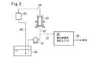
- FIG. 2 shows an example in which the oxidant concentration measuring apparatus of the present invention is applied to a cleaning liquid production system by electrolysis of a sulfuric acid solution.
- the electrolytic solution is fed from the storage tank 20 to the electrolytic cell 23 through the pipe 22 including the pump 21.
- the electrolytic treatment liquid is circulated to the storage tank 20 through the pipe 24, the gas-liquid separator 25, and the pipe 26.
- a sorting pipe 27 for sorting a part of the electrolyte solution is provided on the downstream side of the pump 21 of the pipe 22, a sorting pipe 27 for sorting a part of the electrolyte solution is provided.
- a part of the electrolytic solution is collected from the pipe 22 and is supplied to the oxidant concentration measuring unit 28 which is the oxidant concentration measuring device of the present invention, and the oxidant concentration is measured.
- the liquid after the measurement is discharged out of the system through the pipe 29.
- a cleaning liquid made of electrolytic sulfuric acid having a desired oxidizing agent concentration is manufactured by adjusting the electrolysis conditions of the electrolytic cell 23 based on the measurement result of the oxidizing agent concentration in the oxidizing agent concentration measuring unit 28. .
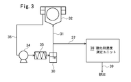
- 3 to 5 are system diagrams showing an embodiment of an electronic material cleaning apparatus to which the oxidant concentration measuring apparatus of the present invention is applied.
- FIG. 3 shows an application of the oxidant concentration measuring device of the present invention to a batch type cleaning machine using SPM as a cleaning liquid.
- the cleaning liquid in the storage tank 30 is supplied to the cleaning machine 32 through the pipe 31.
- the washing waste liquid is circulated to the storage tank 30 through a pipe 36 having a pump 34 and a heat exchanger 35.
- the pipe 31 is branched by a sorting pipe 37 for sorting a part of the cleaning liquid supplied to the cleaning machine 32 as a sample liquid.
- the cleaning liquid collected by the pipe 37 is supplied to an oxidant concentration measuring unit 38 which is an oxidant concentration measuring device of the present invention, and the oxidant concentration is measured.
- the measured sample solution is discharged out of the system through the pipe 39.
- FIG. 4 shows a batch type washing machine using electrolytic sulfuric acid as a washing liquid, and applying the oxidant concentration measuring device of the present invention.
- the electrolytic sulfuric acid in the storage tank 40 is supplied as a cleaning liquid to a cleaning machine 44 through pipes 42 and 43 having a pump 41.
- the washing waste liquid is discharged through a pipe 46 having a pump 45.
- a part of the washing waste liquid is circulated to the washing machine 44 through a pipe 48 having a heater 47.
- the remaining portion of the cleaning waste liquid is returned to the storage tank 40 through a pipe 50 having a cooler 49.
- the electrolytic sulfuric acid (sulfuric acid solution) in the storage tank 40 is supplied to the electrolyzer 55 through a pipe 53 including a pump 51 and a cooler 52.
- the peroxydisulfuric acid is generated by electrolysis in the electrolyzer 55 and the sulfuric acid solution containing peroxodisulfuric acid is returned to the storage tank 40 via the pipe 56.
- the storage tank 40 is provided with a pure water supply pipe 57 and a concentrated sulfuric acid supply pipe 58.
- a part of the electrolytic sulfuric acid in the storage tank 40 is taken out from the pipe 59 and sent to the oxidant concentration measurement unit 60 which is the oxidant concentration measurement device of the present invention, and the oxidant concentration is measured.
- the measured sample solution is discharged out of the system through the pipe 61.
- FIG. 5 shows an example in which the oxidant concentration measuring device of the present invention is applied to a single wafer cleaning machine using electrolytic sulfuric acid as a cleaning liquid.
- the same members as those shown in FIG. 4 are denoted by the same reference numerals.
- Reference numeral 70 denotes a decomposition tank for oxidizing and decomposing residual organic substances such as resist contained in the cleaning drainage discharged from the single wafer cleaning machine 80 through the pipe 71 with the oxidizing agent contained in the cleaning drainage. .
- the electrolytic sulfuric acid in the storage tank 40 is fed from the pipe 42 provided with the pump 41 to the single-wafer cleaning machine 80 through the filter 72 and the heater 73 as in FIG.
- the cleaning effluent used for cleaning the semiconductor wafer in the single wafer cleaning machine 80 is sent to the decomposition tank 70 via the pipe 71.
- the cleaning effluent treated in the decomposition tank 70 is returned to the storage tank 40 through a pipe 50 including a pump 45 and a cooler 49.
- the electrolytic treatment of the electrolytic sulfuric acid in the storage tank 40 and the measurement of the oxidant concentration are performed in the same manner as the treatment in FIG.
- a part of the cleaning waste liquid is appropriately discharged out of the system through a pipe 74 branched from the pipe 71.
- the cleaning solution is oxidized.
- efficient cleaning can be performed with a cleaning liquid having an appropriate oxidant concentration.
- the measurement method is evaluated as “ ⁇ ”. ".
- an ultraviolet-visible spectrophotometer manufactured by JASCO Corporation was used as the flow-type absorptiometer.
- a Ti standard solution (10000 ppm) was used as a Ti source to be added to the sample solution, and a Co standard solution (10000 ppm) was appropriately diluted as a Co source.
- Electrolytic sulfuric acid (sulfuric acid concentration 92% by weight, charged oxidant concentration 0.01 mol / L) was introduced into a flow-type absorptiometer at 1 L / min, and the absorbance at a wavelength of 253 nm was measured. Was quantified. The oxidizing agent concentration was 0.01 mol / L.
- Electrolytic sulfuric acid having a sulfuric acid concentration and an oxidizing agent concentration shown in Table 1 was used as a sample solution.
- the flow equation shown in FIG. 1 was used.
- the electrolytic sulfuric acid of the sample solution was injected into the ultrapure water flowing through the pipe 12 at 1 mL / min and the pipe 11 at 400 mL / min, mixed and diluted, and then 75 g / L potassium iodide aqueous solution was injected from the pipe 13 at 5 mL / min. And mixed.
- the mixed solution was introduced into the flow type absorptiometer 1 and the absorbance at a wavelength of 290 nm was measured to quantify the oxidant concentration before addition of the metal.
- the potassium iodide aqueous solution is obtained by diluting 375 g / L potassium iodide 1 mL / min from the pipe 14 with 4 mL / min ultrapure water from the pipe 13.
- Example 8 Using SPM 40: 1 as the sample solution, the oxidizing agent concentration before and after the metal addition was determined in the same manner as in Example 3. The results are shown in Table 1.
- Example 9 The sample liquid was SPM (liquid obtained by mixing 96 wt% sulfuric acid and 30 wt% hydrogen peroxide water at a ratio of 4: 1 (weight ratio)) (hereinafter referred to as “SPM 4: 1”) in the same manner as in Example 3.
- SPM 4: 1 liquid obtained by mixing 96 wt% sulfuric acid and 30 wt% hydrogen peroxide water at a ratio of 4: 1 (weight ratio)
- Example 10 The oxidant concentration before and after the metal addition was determined in the same manner as in Example 3 using SOM (a solution obtained by blowing ozone into 92% by weight sulfuric acid) as a sample solution. The results are shown in Table 1.
- Example 11 The sample solution before and after the metal addition as in Example 3 was measured for the oxidant concentration as the following batch method instead of the flow method. The results are shown in Table 1.
- Batch type measurement is performed by adding 400 mL of ultrapure water, 1 mL of electrolytic sulfuric acid and 5 mL of 75 g / L potassium iodide solution to a beaker and mixing them with an absorptiometer (UV-Vis spectrophotometer manufactured by JASCO Corporation). The measurement was performed by measuring the absorbance at a wavelength of 290 nm.
- an absorptiometer UV-Vis spectrophotometer manufactured by JASCO Corporation.
- the oxidizing agent concentration in sulfuric acid solutions such as electrolytic sulfuric acid, SPM, SOM, etc. having various oxidizing agent concentrations, sulfuric acid concentrations, and metal concentrations can be easily operated by both flow and batch methods. It is possible to measure accurately without being affected by metal.
- the absorbance at a wavelength of 290 nm was measured, but the same measurement result could be obtained in the measurement of absorbance at a wavelength of 300 nm, 350 nm, and 355 nm.
Landscapes
- Chemical & Material Sciences (AREA)
- Physics & Mathematics (AREA)
- Life Sciences & Earth Sciences (AREA)
- Health & Medical Sciences (AREA)
- General Physics & Mathematics (AREA)
- Biochemistry (AREA)
- General Health & Medical Sciences (AREA)
- Analytical Chemistry (AREA)
- Immunology (AREA)
- Pathology (AREA)
- Plasma & Fusion (AREA)
- Engineering & Computer Science (AREA)
- Chemical Kinetics & Catalysis (AREA)
- Molecular Biology (AREA)
- Investigating Or Analyzing Non-Biological Materials By The Use Of Chemical Means (AREA)
- Investigating Or Analysing Materials By The Use Of Chemical Reactions (AREA)
- Cleaning Or Drying Semiconductors (AREA)
- Investigating Or Analysing Materials By Optical Means (AREA)
Abstract
金属と酸化剤を含む硫酸溶液中の酸化剤濃度を、金属等の不純物の影響を受けることなく精度良く効率的に測定することができ、オンライン化も容易な酸化剤濃度の測定方法を提供する。金属と酸化剤を含む硫酸溶液とヨウ化カリウム溶液とを混合し、波長200~600nmのいずれかのUV吸光度を測定し、この測定結果に基づいて硫酸溶液の酸化剤濃度を定量する。金属及び酸化剤を含む硫酸溶液にヨウ化カリウム(KI)溶液を添加して硫酸溶液中の酸化性物質をKIと選択的に反応させて遊離したヨウ素により黄色く発色させることにより、金属等の不純物よりもUV感度が高くなり、金属等の不純物の影響を低減して高精度にUV吸光度を測定することができる。
Description
本発明は、金属と酸化剤を含む硫酸溶液中の酸化剤濃度を測定する方法及び装置に関する。本発明はまた、この装置を利用した電子材料洗浄装置に関する。
半導体製造工程においては、SPM(硫酸と過酸化水素水の混合液)、SOM(オゾン吹き込み硫酸)、電解硫酸といった硫酸系酸化剤溶液が、レジストの除去や金属のエッチング等に使用されている。硫酸系酸化剤溶液を用いたレジストの除去や金属のエッチングにおいて、処理効果に及ぼす硫酸系酸化剤溶液中の酸化剤の濃度の影響は大きい。このため、硫酸系酸化剤溶液の酸化剤濃度の測定と管理が重要な要件となっている。
SPMや電解硫酸中の酸化剤濃度を測定する方法として、以下の方法がある。
(1) 紫外線(UV)の吸光度測定による方法:測定対象溶液のUVの吸光度を測定し、測定値から酸化剤を定量する(特許文献1)。
(2) ヨウ化カリウムを添加してチオ硫酸ナトリウムで滴定する方法:測定対象溶液にヨウ化カリウム溶液を添加混合し、遊離したヨウ素をチオ硫酸ナトリウムで滴定し、その結果から酸化剤を定量する(以下、「KI滴定法」と称す。)(特許文献2,3)。
(1) 紫外線(UV)の吸光度測定による方法:測定対象溶液のUVの吸光度を測定し、測定値から酸化剤を定量する(特許文献1)。
(2) ヨウ化カリウムを添加してチオ硫酸ナトリウムで滴定する方法:測定対象溶液にヨウ化カリウム溶液を添加混合し、遊離したヨウ素をチオ硫酸ナトリウムで滴定し、その結果から酸化剤を定量する(以下、「KI滴定法」と称す。)(特許文献2,3)。
SPMや電解硫酸といった酸化剤含有硫酸溶液でウエハを洗浄し、洗浄排液を回収し、酸化性物質を再生して再使用する場合、ウエハからの金属などの溶出物が洗浄排液に残留し、再生後の洗浄液に混入してしまう恐れがある。
特許文献1のUV吸光度の測定による酸化剤の定量方法では、測定対象溶液に金属が混入すると、UV吸光度が金属の影響を受け、酸化剤濃度を正確に定量することができない。
特許文献2,3のKI滴定法は、滴定操作が必要であるため、操作が煩雑である。ウエハ洗浄において、酸化剤濃度の即時的なモニタリングは重要であり、オンラインでのモニタリングが求められるが、特許文献2,3のKI滴定法ではオンライン化が困難である。
本発明は、金属と酸化剤を含む硫酸溶液中の酸化剤濃度を、金属等の不純物の影響を受けることなく、精度良く効率的に測定することができ、オンライン化も容易な酸化剤濃度の測定方法及び測定装置と、これを利用した電子材料洗浄装置を提供することを目的とする。
本発明者は、硫酸溶液にヨウ化カリウム溶液を添加混合した後吸光度を測定することにより、混入した金属等の不純物の影響を受けることなく、硫酸溶液中の酸化剤濃度を簡便かつ高精度に測定することができることを確認した。
本発明は、以下を要旨とする。
本発明は、以下を要旨とする。
[1] 金属と酸化剤を含む硫酸溶液の酸化剤濃度を測定する方法であって、該硫酸溶液とヨウ化カリウム溶液を混合する混合工程と、得られた混合液の波長200~600nmのいずれかの吸光度を測定する吸光度測定工程と、該吸光度の測定結果に基づいて該硫酸溶液の酸化剤濃度を定量する定量工程とを有する酸化剤濃度の測定方法。
[2] [1]において、前記硫酸溶液とヨウ化カリウム溶液との混合に先立ち、或いは混合時に、前記硫酸溶液を硫酸濃度20重量%以下に調整する希釈工程を含むことを特徴とする酸化剤濃度の測定方法。
[3] [1]又は[2]において、前記硫酸溶液が、半導体ウエハの洗浄液又は該半導体ウエハの洗浄に用いられた洗浄排液であり、前記半導体ウエハの洗浄工程に洗浄液を送給する洗浄液送給系、又は、前記半導体ウエハの洗浄工程から洗浄排液を排出する洗浄排液排出系から、該洗浄液又は洗浄排液の一部を分取して酸化剤濃度をオンライン測定することを特徴とする酸化剤濃度の測定方法。
[4] 金属と酸化剤を含む硫酸溶液の酸化剤濃度を測定する装置であって、該硫酸溶液とヨウ化カリウム溶液を混合する混合手段と、得られた混合液の波長200~600nmのいずれかの吸光度を測定する吸光度測定手段と、該吸光度の測定結果に基づいて該硫酸溶液の酸化剤濃度を定量する定量手段と
を有する酸化剤濃度の測定装置。
を有する酸化剤濃度の測定装置。
[5] [4]において、前記硫酸溶液とヨウ化カリウム溶液との混合に先立ち、或いは混合時に、前記硫酸溶液を硫酸濃度20重量%以下に調整する希釈手段を含むことを特徴とする酸化剤濃度の測定装置。
[6] [4]又は[5]において、前記硫酸溶液が、半導体ウエハの洗浄液又は該半導体ウエハの洗浄に用いられた洗浄排液であり、前記半導体ウエハの洗浄工程に洗浄液を送給する洗浄液送給系、又は、前記半導体ウエハの洗浄工程から洗浄排液を排出する洗浄排液排出系から、該洗浄液又は洗浄排液の一部を分取する分取手段を有し、該分取手段で分取された洗浄液又は洗浄排液の酸化剤濃度がオンライン測定されることを特徴とする酸化剤濃度の測定装置。
[7] 電子材料の洗浄手段と、該洗浄手段に洗浄液を送給する洗浄液送給手段と、該洗浄手段からの洗浄排液を排出する洗浄排液排出手段と、該洗浄液送給手段又は洗浄排液排出手段から洗浄液又は洗浄排液の一部を分取する分取手段と、該分取手段で分取された洗浄液又は洗浄排液の酸化剤濃度を測定する酸化剤濃度測定手段とを備える電子材料洗浄装置であって、該酸化剤濃度測定手段が、[4]ないし[6]のいずれかに記載の酸化剤濃度の測定装置を備えることを特徴とする電子材料洗浄装置。
[8] [7]において、前記洗浄手段で洗浄に使用された洗浄排液を再生する再生手段と、該再生手段で再生された液を洗浄液として前記洗浄手段に循環する循環手段とを備えることを特徴とする電子材料洗浄装置。
[9] [7]又は[8]において、前記電子材料が、表面の少なくとも一部に金属が露出している半導体ウエハであることを特徴とする電子材料洗浄装置。
本発明の酸化剤濃度の測定方法及び測定装置によれば、電子材料の洗浄工程で使用されている金属が混入した硫酸系酸化剤溶液等の金属と酸化剤を含む硫酸溶液中の酸化剤濃度を、金属等の混入不純物に影響されることなく、簡便かつ安定的に、高精度に測定することができる。また、オンラインでの連続モニタリングも容易に行える。
従って、SPMや電解硫酸といった硫酸系酸化剤溶液で半導体ウエハを洗浄し、ウエハ洗浄に起因する金属やレジストが混入した場合でも、金属等の不純物に影響されることなく硫酸系酸化剤溶液中の酸化剤の濃度を的確に測定することができる。
本発明の電子材料洗浄装置によれば、硫酸系酸化剤溶液による洗浄排液を回収して硫酸系酸化剤溶液中の酸化剤を再生して洗浄に再利用する場合に、この測定技術を利用して、洗浄液中の酸化剤濃度を正確にモニタリングすることができ、所定の酸化剤濃度の洗浄液により効率的な洗浄を行うことができる。
以下に本発明の実施の形態を詳細に説明する。
<メカニズム>
本発明では、金属及び酸化剤を含む硫酸溶液にヨウ化カリウム(KI)溶液を添加して硫酸溶液中のペルオキソ二硫酸等の酸化剤(酸化性物質)を、以下の反応式でKIと選択的に反応させて遊離したヨウ素(I2)により黄色く発色させる。これにより、金属等の不純物よりも酸化性物質に起因する反応生成物のUV感度が高くなり、金属の影響を低減して高精度で酸化性物質由来の吸光度を測定することができる。
H2SO5+2KI→I2(淡黄色)+K2SO4+H2O
H2S2O8+4KI→2I2(淡黄色)+2K2SO4+H2
H2O2+H2SO4+2KI→I2(淡黄色)+K2SO4+2H2O
本発明では、金属及び酸化剤を含む硫酸溶液にヨウ化カリウム(KI)溶液を添加して硫酸溶液中のペルオキソ二硫酸等の酸化剤(酸化性物質)を、以下の反応式でKIと選択的に反応させて遊離したヨウ素(I2)により黄色く発色させる。これにより、金属等の不純物よりも酸化性物質に起因する反応生成物のUV感度が高くなり、金属の影響を低減して高精度で酸化性物質由来の吸光度を測定することができる。
H2SO5+2KI→I2(淡黄色)+K2SO4+H2O
H2S2O8+4KI→2I2(淡黄色)+2K2SO4+H2
H2O2+H2SO4+2KI→I2(淡黄色)+K2SO4+2H2O
<金属及び酸化剤を含む硫酸溶液>
本発明において、酸化剤濃度の測定対象となる硫酸溶液は、金属及び酸化剤を含むものであり、特に制限はない。本発明は、表面の少なくとも一部に金属が露出している半導体ウエハの洗浄に用いることにより、不純物として金属を含む電解硫酸、SPM、SOM等の硫酸系酸化剤溶液の酸化剤濃度の測定に有用である。特に、本発明は、このような硫酸系酸化剤溶液を洗浄液として用いて半導体ウエハの洗浄を行い、洗浄排液を回収して酸化剤を再生して洗浄液として循環再利用する場合において、洗浄工程に送給される洗浄液や洗浄工程から排出された洗浄排液中の酸化剤濃度をオンライン測定して濃度管理する場合に有効である。
本発明において、酸化剤濃度の測定対象となる硫酸溶液は、金属及び酸化剤を含むものであり、特に制限はない。本発明は、表面の少なくとも一部に金属が露出している半導体ウエハの洗浄に用いることにより、不純物として金属を含む電解硫酸、SPM、SOM等の硫酸系酸化剤溶液の酸化剤濃度の測定に有用である。特に、本発明は、このような硫酸系酸化剤溶液を洗浄液として用いて半導体ウエハの洗浄を行い、洗浄排液を回収して酸化剤を再生して洗浄液として循環再利用する場合において、洗浄工程に送給される洗浄液や洗浄工程から排出された洗浄排液中の酸化剤濃度をオンライン測定して濃度管理する場合に有効である。
<ヨウ化カリウム溶液の混合>
ヨウ化カリウム溶液としては、取り扱い性の観点から、10~200g/L程度のヨウ化カリウム水溶液が挙げられる。
ヨウ化カリウム溶液としては、取り扱い性の観点から、10~200g/L程度のヨウ化カリウム水溶液が挙げられる。
測定対象である硫酸溶液へのヨウ化カリウム溶液の添加量は、硫酸溶液中の酸化剤濃度によって適宜決定される。
ヨウ化カリウム溶液は、測定対象である硫酸溶液中のペルオキシ硫酸、過酸化水素、オゾン等の酸化性物質に対して、KI添加量が5~20倍(体積比)程度となるように添加することが好ましい。
ヨウ化カリウム溶液を添加する硫酸溶液の硫酸濃度が高過ぎると発泡する問題がある。測定対象の硫酸溶液の硫酸濃度が高い場合には水(純水又は超純水)で硫酸濃度が20重量%以下、例えば5~15重量%となるように希釈混合した上でヨウ化カリウム溶液を添加することが好ましい。この場合は予め設定した希釈倍率となるよう希釈し、吸光度の測定値と希釈倍率とに基づいて酸化剤濃度を算出する。希釈はヨウ化カリウム溶液の混合前に行ってもよい。ヨウ化カリウム溶液と共に希釈水を添加混合してもよい。
<吸光度測定>
金属及び酸化剤を含む硫酸溶液を必要に応じて希釈し、ヨウ化カリウム溶液を添加混合した後に、波長200~600nmのいずれかの吸光度を測定する。測定波長は好ましくは200~500nmであり、より好ましくは250~400nmである。
金属及び酸化剤を含む硫酸溶液を必要に応じて希釈し、ヨウ化カリウム溶液を添加混合した後に、波長200~600nmのいずれかの吸光度を測定する。測定波長は好ましくは200~500nmであり、より好ましくは250~400nmである。
吸光度は市販の吸光光度計を用いて測定することができる。
<酸化剤濃度の定量>
吸光度の測定結果から、酸化剤濃度を定量するには例えば、以下の方法を採用する。
吸光度の測定結果から、酸化剤濃度を定量するには例えば、以下の方法を採用する。
測定対象とする硫酸溶液と同一の硫酸濃度で酸化剤濃度を変更した標準試料液を多種類調製する。この標準試料液について、予めヨウ化カリウム溶液を添加混合した後の吸光度を測定して、吸光度と酸化剤濃度の検量線を作製する。測定対象の硫酸溶液の吸光度の測定値をこの検量線にあてはめて、酸化剤濃度を求める。
吸光度による酸化剤濃度の定量は、酸化剤濃度が低いと測定誤差が大きくなる傾向がある。酸化剤濃度が高いと吸光度が測定範囲を超えてしまい追随できなくなり、酸化剤濃度と吸光度との検量関係がなくなる。従って、本発明の測定対象液は酸化剤濃度が測定濃度として、0.001~1mol/L程度であることが好ましい。この測定濃度とは、酸化剤濃度を測定する希釈前の金属及び酸化剤を含む硫酸溶液の酸化剤濃度である。
通常、半導体ウエハの洗浄に用いられる電解硫酸、SPM、SOMの硫酸濃度及び酸化剤濃度は以下の範囲であるため、本発明を有効に適用することができる。
電解硫酸:硫酸濃度=10~96重量%
酸化剤濃度=0.001~1mol/L
SPM :硫酸濃度=10~96重量%
酸化剤濃度=0.01~10mol/L
SOM :硫酸濃度=10~96重量%
酸化剤濃度=0.001~1mol/L
電解硫酸:硫酸濃度=10~96重量%
酸化剤濃度=0.001~1mol/L
SPM :硫酸濃度=10~96重量%
酸化剤濃度=0.01~10mol/L
SOM :硫酸濃度=10~96重量%
酸化剤濃度=0.001~1mol/L
<オンライン測定>
本発明による酸化剤濃度の測定は、混合槽内で、測定対象の硫酸溶液の希釈とヨウ化カリウム溶液との混合を行った後、混合液の吸光度を測定するバッチ方式で行うことができる。フロー式吸光光度計を用いることにより、これらをライン混合することで、オンライン化が容易となる。
本発明による酸化剤濃度の測定は、混合槽内で、測定対象の硫酸溶液の希釈とヨウ化カリウム溶液との混合を行った後、混合液の吸光度を測定するバッチ方式で行うことができる。フロー式吸光光度計を用いることにより、これらをライン混合することで、オンライン化が容易となる。
図1を参照して、ライン混合を採用した本発明の酸化剤濃度の測定装置を説明する。
図1の酸化剤濃度の測定装置では、ポンプP1を有するフロー式吸光光度計1への試料液導入配管11に、希釈用の純水が導入される。配管11に、半導体ウエハの洗浄工程からの酸化剤含有硫酸系洗浄液等の金属と酸化剤を含む硫酸溶液がポンプP2を有する配管12より注入され、この酸化剤含有硫酸系洗浄液が純水により希釈される。
酸化剤含有硫酸系洗浄液の注入点よりも下流側にヨウ化カリウム溶液を注入するためのポンプP3を有する配管13が接続されている。配管13より、希釈された酸化剤含有硫酸系洗浄液にヨウ化カリウム溶液が注入される。ヨウ化カリウム溶液は、ポンプP4を有する配管14からの高濃度ヨウ化カリウム溶液を、純水が導入される配管13に注入して希釈され濃度調整されたものである。
ヨウ化カリウム溶液が注入された後の液は、更にラインミキサ2で混合された後、混合液がフロー式吸光光度計1に導入され、吸光度の測定が行われる。測定後の液は、ヨウ化カリウムを含み、洗浄液として用いることはできないため、系外に排出される。
図1の酸化剤濃度の測定装置によれば、各配管の純水や硫酸溶液、ヨウ化カリウム溶液の流量を調整することにより、所定濃度範囲に希釈された硫酸溶液に所定量のヨウ化カリウム溶液を添加混合してフロー式吸光光度計1で吸光度の測定を行うことができる。この測定装置を例えば半導体ウエハの洗浄装置に組み込むことで、洗浄工程に送給される洗浄液や洗浄工程から排出される洗浄排液の酸化剤濃度を迅速かつ的確に測定することができる。
特に制限するものではないが各配管の流量は、例えば以下の通りである。
配管11:0.5~200ml/minで配管12の流量の5~2000倍
配管12:0.1~50ml/min
配管13:20~1000ml/minで配管12の流量の200~10000倍
配管11:0.5~200ml/minで配管12の流量の5~2000倍
配管12:0.1~50ml/min
配管13:20~1000ml/minで配管12の流量の200~10000倍
<適用例>
図2は、本発明の酸化剤濃度の測定装置を、硫酸溶液の電気分解による洗浄液製造システムに適用した例を示す。貯留槽20からポンプ21を備える配管22より被電解液が電解セル23に送給される。電解処理液は配管24、気液分離器25、配管26を経て貯留槽20に循環される。配管22のポンプ21の下流側には、被電解液の一部を分取する分取配管27が設けられている。配管22から被電解液の一部が分取され、本発明の酸化剤濃度の測定装置である酸化剤濃度測定ユニット28に送給され、酸化剤濃度の測定が行われる。測定後の液は配管29を経て系外へ排出される。
図2は、本発明の酸化剤濃度の測定装置を、硫酸溶液の電気分解による洗浄液製造システムに適用した例を示す。貯留槽20からポンプ21を備える配管22より被電解液が電解セル23に送給される。電解処理液は配管24、気液分離器25、配管26を経て貯留槽20に循環される。配管22のポンプ21の下流側には、被電解液の一部を分取する分取配管27が設けられている。配管22から被電解液の一部が分取され、本発明の酸化剤濃度の測定装置である酸化剤濃度測定ユニット28に送給され、酸化剤濃度の測定が行われる。測定後の液は配管29を経て系外へ排出される。
この洗浄液製造システムでは、酸化剤濃度測定ユニット28での酸化剤濃度の測定結果に基づいて、電解セル23の電解条件を調整することにより、所望の酸化剤濃度の電解硫酸よりなる洗浄液を製造する。
<電子材料洗浄装置>
図3~5を参照して、本発明の酸化剤濃度の測定装置を用いた電子材料洗浄装置について説明する。
図3~5を参照して、本発明の酸化剤濃度の測定装置を用いた電子材料洗浄装置について説明する。
図3~5は、本発明の酸化剤濃度の測定装置を適用した電子材料洗浄装置の実施の形態を示す系統図である。
図3は、SPMを洗浄液とするバッチ式洗浄機に本発明の酸化剤濃度の測定装置を適用したものを示す。貯留槽30内の洗浄液が配管31を経て洗浄機32に送給される。洗浄排液はポンプ34及び熱交換器35を有する配管36を経て貯留槽30に循環される。配管31には洗浄機32に送給される洗浄液の一部を試料液として分取する分取配管37が分岐している。配管37で分取された洗浄液は、本発明の酸化剤濃度の測定装置である酸化剤濃度測定ユニット38に送給されて酸化剤濃度の測定が行われる。測定後の試料液は配管39を経て系外へ排出される。
図4は、電解硫酸を洗浄液とするバッチ式洗浄機に本発明の酸化剤濃度の測定装置を適用したものを示す。貯留槽40内の電解硫酸は洗浄液としてポンプ41を有する配管42,43を経て洗浄機44に送給される。洗浄排液はポンプ45を有する配管46を経て排出される。洗浄排液の一部は加熱器47を有する配管48を経て洗浄機44に循環される。洗浄排液の残部は冷却器49を有する配管50を経て貯留槽40に戻される。
貯留槽40内の電解硫酸(硫酸溶液)は、ポンプ51、冷却器52を備える配管53を経て電解装置55に送給される。電解装置55における電気分解でペルオキソ二硫酸を生成してペルオキソ二硫酸を含む硫酸溶液は配管56を経て貯留槽40に戻される。貯留槽40には純水供給配管57と濃硫酸供給配管58が設けられている。
貯留槽40内の電解硫酸の一部が配管59より取り出され、本発明の酸化剤濃度の測定装置である酸化剤濃度測定ユニット60に送給されて酸化剤濃度の測定が行われる。測定後の試料液は配管61を経て系外へ排出される。
図5は、電解硫酸を洗浄液とする枚葉式洗浄機に、本発明の酸化剤濃度の測定装置を適用した例を示す。図5において、図4に示す部材と同一の部材には同一符号を付してある。
70は分解槽であり、枚葉式洗浄機80から配管71を経て排出される洗浄排液に含まれるレジストなどの残留有機物を洗浄排液に含まれる酸化剤で酸化分解するためのものである。
貯留槽40内の電解硫酸は図4におけると同様にポンプ41を備える配管42から、フィルタ72、加熱機73を経て枚葉式洗浄機80に送給される。枚葉式洗浄機80において半導体ウエハの洗浄に使用された洗浄排液は、配管71を経て分解槽70に送給される。分解槽70で処理された洗浄排液はポンプ45及び冷却器49を備える配管50を経て貯留槽40に戻される。貯留槽40内の電解硫酸の電解処理及び酸化剤濃度の測定は図4における処理と同様に行われる。
洗浄排液の一部は配管71から分岐する配管74より適宜系外へ排出される。
図3~5に示すように、電子材料の洗浄装置に本発明の酸化剤濃度の測定装置を適用して、洗浄液である硫酸系酸化剤溶液の酸化剤濃度を測定することにより、洗浄液の酸化剤濃度を洗浄中にオンタイムで検出し、必要に応じて洗浄液の酸化剤濃度の調整を行うことにより、適切な酸化剤濃度の洗浄液により効率的な洗浄を行うことが可能となる。
以下に実施例を挙げて本発明をより具体的に説明する。
以下において、金属添加前後の試料液の酸化剤濃度の測定結果の誤差が40%以下であれば測定法としても良い「○」と評価し、この誤差が40%より大きい場合には不良「×」として評価した。
フロー式吸光光度計としては日本分光社製の紫外可視分光光度計を用いた。試料液に添加するTi源としてはTi標準液(10000ppm)を用い、Co源としてはCo標準液(10000ppm)を、適宜希釈して用いた。
[比較例1]
電解硫酸(硫酸濃度92重量%、仕込み酸化剤濃度0.01mol/L)を1L/minでフロー式吸光光度計に導入し、波長253nmでの吸光度を測定して、金属添加前の酸化剤濃度を定量した。酸化剤濃度は0.01mol/Lであった。
電解硫酸(硫酸濃度92重量%、仕込み酸化剤濃度0.01mol/L)を1L/minでフロー式吸光光度計に導入し、波長253nmでの吸光度を測定して、金属添加前の酸化剤濃度を定量した。酸化剤濃度は0.01mol/Lであった。
次に、この電解硫酸にTi10mg/L及びCo10mg/LとなるようにTi源、Co源を添加した溶液を調製し、波長253nmでの吸光度を測定して、金属添加後の酸化剤濃度を定量した。酸化剤濃度は0.08mol/Lであり、金属添加前に対する測定濃度の誤差は700%(={(0.08-0.01)/0.01}×100)であった。
これらの結果を表1に示す。
これらの結果を表1に示す。
[比較例2]
SPM(96重量%硫酸と30重量%過酸化水素水を40:1(重量比)で混合した液)(以下「SPM40:1」と記載する。)を試料液として、比較例1と同様にして、金属添加前後の酸化剤濃度を求めた。結果を表1に示す。
SPM(96重量%硫酸と30重量%過酸化水素水を40:1(重量比)で混合した液)(以下「SPM40:1」と記載する。)を試料液として、比較例1と同様にして、金属添加前後の酸化剤濃度を求めた。結果を表1に示す。
[比較例3]
SOM(92重量%硫酸にオゾンを吹き込んだ液)を試料液として、比較例1と同様にして金属添加前後の酸化剤濃度を求めた。結果を表1に示す。
SOM(92重量%硫酸にオゾンを吹き込んだ液)を試料液として、比較例1と同様にして金属添加前後の酸化剤濃度を求めた。結果を表1に示す。
[比較例4]
比較例1におけると同様の試料液を用い、KI滴定法で金属添加前後の酸化剤濃度を求めた。結果を表1に示す。
比較例1におけると同様の試料液を用い、KI滴定法で金属添加前後の酸化剤濃度を求めた。結果を表1に示す。
[実施例1~7]
表1に示す硫酸濃度及び酸化剤濃度の電解硫酸を試料液とした。図1に示すフロー式で行った。試料液の電解硫酸を配管12より1mL/minで、配管11を400mL/minで流れる超純水に注入して混合希釈した後、配管13より75g/Lヨウ化カリウム水溶液を5mL/minで注入して混合した。混合液をフロー式吸光光度計1に導入し、波長290nmでの吸光度を測定して、金属添加前の酸化剤濃度を定量した。
表1に示す硫酸濃度及び酸化剤濃度の電解硫酸を試料液とした。図1に示すフロー式で行った。試料液の電解硫酸を配管12より1mL/minで、配管11を400mL/minで流れる超純水に注入して混合希釈した後、配管13より75g/Lヨウ化カリウム水溶液を5mL/minで注入して混合した。混合液をフロー式吸光光度計1に導入し、波長290nmでの吸光度を測定して、金属添加前の酸化剤濃度を定量した。
ヨウ化カリウム水溶液は、配管14からの375g/Lヨウ化カリウム1mL/minを、配管13からの4mL/minの超純水と混合して希釈したものである。
次に硫酸濃度、酸化剤濃度が同じで、Ti及びCo濃度が表1となるように調製した溶液を試料液として、上記と同様にして金属添加後の酸化剤濃度を求めた。
これらの結果を表1に示す。
これらの結果を表1に示す。
[実施例8]
試料液としてSPM40:1を用い、実施例3と同様にして、金属添加前後の酸化剤濃度を求めた。結果を表1に示す。
試料液としてSPM40:1を用い、実施例3と同様にして、金属添加前後の酸化剤濃度を求めた。結果を表1に示す。
[実施例9]
SPM(96重量%硫酸と30重量%過酸化水素水を4:1(重量比)で混合した液)(以下「SPM4:1」と記載する。)を試料液として、実施例3と同様にして、金属添加前後の酸化剤濃度を求めた。結果を表1に示す。
SPM(96重量%硫酸と30重量%過酸化水素水を4:1(重量比)で混合した液)(以下「SPM4:1」と記載する。)を試料液として、実施例3と同様にして、金属添加前後の酸化剤濃度を求めた。結果を表1に示す。
[実施例10]
SOM(92重量%硫酸にオゾンを吹き込んだ液)を試料液として、実施例3と同様にして、金属添加前後の酸化剤濃度を求めた。結果を表1に示す。
SOM(92重量%硫酸にオゾンを吹き込んだ液)を試料液として、実施例3と同様にして、金属添加前後の酸化剤濃度を求めた。結果を表1に示す。
[実施例11]
フロー式ではなく、以下のバッチ式として、実施例3と同様の金属添加前後の試料液について酸化剤濃度の測定を行った。結果を表1に示す。
フロー式ではなく、以下のバッチ式として、実施例3と同様の金属添加前後の試料液について酸化剤濃度の測定を行った。結果を表1に示す。
バッチ式の測定は、ビーカーに超純水400mLと電解硫酸1mLと75g/Lヨウ化カリウム溶液5mLとを添加して混合し、吸光光度計(日本分光社製の紫外可視分光光度計)にて波長290nmの吸光度を測定することで行った。

表1より明らかなように、従来のUV測定法(比較例1~3)では、操作は簡便であるが、試料液中の金属の影響を受け、測定誤差が大きい。KI滴定法(比較例4)では測定誤差はないものの、操作が煩雑である。
これに対して、本発明によれば、各種の酸化剤濃度、硫酸濃度及び金属濃度の電解硫酸、SPM、SOM等の硫酸溶液中の酸化剤濃度を、フロー式でもバッチ式でも簡便な操作で、金属の影響を受けることなく、精度よく測定することができる。
上記の実施例において、波長290nmの吸光度を測定したが、波長300nm、350nm、355nmの吸光度の測定においても同様の測定結果を得ることができた。
本発明を特定の態様を用いて詳細に説明したが、本発明の意図と範囲を離れることなく様々な変更が可能であることは当業者に明らかである。
本出願は、2016年3月25日付で出願された日本特許出願2016-061469に基づいており、その全体が引用により援用される。
本出願は、2016年3月25日付で出願された日本特許出願2016-061469に基づいており、その全体が引用により援用される。
1 フロー式吸光光度計
2 ラインミキサ
20 貯留槽
23 電解セル
25 気液分離器
28 酸化剤濃度測定ユニット
30 貯留槽
32 洗浄機
38 酸化剤濃度測定ユニット
40 貯留槽
44 洗浄機
47 加熱機
49,52 冷却器
55 電解装置
60 酸化剤濃度測定ユニット
70 分解槽
72 フィルタ
73 加熱機
80 枚葉式洗浄機
2 ラインミキサ
20 貯留槽
23 電解セル
25 気液分離器
28 酸化剤濃度測定ユニット
30 貯留槽
32 洗浄機
38 酸化剤濃度測定ユニット
40 貯留槽
44 洗浄機
47 加熱機
49,52 冷却器
55 電解装置
60 酸化剤濃度測定ユニット
70 分解槽
72 フィルタ
73 加熱機
80 枚葉式洗浄機
Claims (9)
- 金属と酸化剤を含む硫酸溶液の酸化剤濃度を測定する方法であって、
該硫酸溶液とヨウ化カリウム溶液を混合する混合工程と、
得られた混合液の波長200~600nmのいずれかの吸光度を測定する吸光度測定工程と、
該吸光度の測定結果に基づいて該硫酸溶液の酸化剤濃度を定量する定量工程と
を有する酸化剤濃度の測定方法。 - 請求項1において、前記硫酸溶液とヨウ化カリウム溶液との混合に先立ち、或いは混合時に、前記硫酸溶液を硫酸濃度20重量%以下に調整する希釈工程を含むことを特徴とする酸化剤濃度の測定方法。
- 請求項1又は2において、前記硫酸溶液が、半導体ウエハの洗浄液又は該半導体ウエハの洗浄に用いられた洗浄排液であり、前記半導体ウエハの洗浄工程に洗浄液を送給する洗浄液送給系、又は、前記半導体ウエハの洗浄工程から洗浄排液を排出する洗浄排液排出系から、該洗浄液又は洗浄排液の一部を分取して酸化剤濃度をオンライン測定することを特徴とする酸化剤濃度の測定方法。
- 金属と酸化剤を含む硫酸溶液の酸化剤濃度を測定する装置であって、
該硫酸溶液とヨウ化カリウム溶液を混合する混合手段と、
得られた混合液の波長200~600nmのいずれかの吸光度を測定する吸光度測定手段と、
該吸光度の測定結果に基づいて該硫酸溶液の酸化剤濃度を定量する定量手段と
を有する酸化剤濃度の測定装置。 - 請求項4において、前記硫酸溶液とヨウ化カリウム溶液との混合に先立ち、或いは混合時に、前記硫酸溶液を硫酸濃度20重量%以下に調整する希釈手段を含むことを特徴とする酸化剤濃度の測定装置。
- 請求項4又は5において、前記硫酸溶液が、半導体ウエハの洗浄液又は該半導体ウエハの洗浄に用いられた洗浄排液であり、前記半導体ウエハの洗浄工程に洗浄液を送給する洗浄液送給系、又は、前記半導体ウエハの洗浄工程から洗浄排液を排出する洗浄排液排出系から、該洗浄液又は洗浄排液の一部を分取する分取手段を有し、該分取手段で分取された洗浄液又は洗浄排液の酸化剤濃度がオンライン測定されることを特徴とする酸化剤濃度の測定装置。
- 電子材料の洗浄手段と、該洗浄手段に洗浄液を送給する洗浄液送給手段と、該洗浄手段からの洗浄排液を排出する洗浄排液排出手段と、該洗浄液送給手段又は洗浄排液排出手段から洗浄液又は洗浄排液の一部を分取する分取手段と、該分取手段で分取された洗浄液又は洗浄排液の酸化剤濃度を測定する酸化剤濃度測定手段とを備える電子材料洗浄装置であって、該酸化剤濃度測定手段が、請求項4ないし6のいずれか1項に記載の酸化剤濃度の測定装置を備えることを特徴とする電子材料洗浄装置。
- 請求項7において、前記洗浄手段で洗浄に使用された洗浄排液を再生する再生手段と、該再生手段で再生された液を洗浄液として前記洗浄手段に循環する循環手段とを備えることを特徴とする電子材料洗浄装置。
- 請求項7又は8において、前記電子材料が、表面の少なくとも一部に金属が露出している半導体ウエハであることを特徴とする電子材料洗浄装置。
Applications Claiming Priority (2)
| Application Number | Priority Date | Filing Date | Title |
|---|---|---|---|
| JP2016-061469 | 2016-03-25 | ||
| JP2016061469A JP6168184B1 (ja) | 2016-03-25 | 2016-03-25 | 酸化剤濃度の測定方法及び測定装置、並びに電子材料洗浄装置 |
Publications (1)
| Publication Number | Publication Date |
|---|---|
| WO2017163456A1 true WO2017163456A1 (ja) | 2017-09-28 |
Family
ID=59384362
Family Applications (1)
| Application Number | Title | Priority Date | Filing Date |
|---|---|---|---|
| PCT/JP2016/076829 Ceased WO2017163456A1 (ja) | 2016-03-25 | 2016-09-12 | 酸化剤濃度の測定方法及び測定装置、並びに電子材料洗浄装置 |
Country Status (3)
| Country | Link |
|---|---|
| JP (1) | JP6168184B1 (ja) |
| TW (1) | TW201800751A (ja) |
| WO (1) | WO2017163456A1 (ja) |
Cited By (1)
| Publication number | Priority date | Publication date | Assignee | Title |
|---|---|---|---|---|
| CN113607671A (zh) * | 2021-08-26 | 2021-11-05 | 西安热工研究院有限公司 | 一种除去异丙醇中氧化性杂质的装置及方法 |
Families Citing this family (1)
| Publication number | Priority date | Publication date | Assignee | Title |
|---|---|---|---|---|
| JP6995329B1 (ja) * | 2021-09-06 | 2022-01-14 | サラヤ株式会社 | 過カルボン酸濃度測定用指示薬、それを用いた過カルボン酸濃度測定方法 |
Citations (18)
| Publication number | Priority date | Publication date | Assignee | Title |
|---|---|---|---|---|
| JPS5583849A (en) * | 1978-12-21 | 1980-06-24 | Toshiba Corp | Measuring method of melted ozone density |
| JPS5548254B2 (ja) * | 1975-04-16 | 1980-12-04 | ||
| JPS62134558A (ja) * | 1985-12-09 | 1987-06-17 | Yokohama Metsukin Kogyo Kk | 次亜塩素酸塩中の有効塩素量の測定方法 |
| JPH04351948A (ja) * | 1991-05-30 | 1992-12-07 | Dowa Mining Co Ltd | 還元性物質及び酸化性物質の検出方法及びその装置 |
| JPH07333210A (ja) * | 1994-06-06 | 1995-12-22 | Meidensha Corp | 硝酸イオンと亜硝酸イオンの分析方法及び分析装置 |
| JP2000180430A (ja) * | 1998-12-17 | 2000-06-30 | Nippon Steel Corp | 水中の水酸化ラジカルの測定方法 |
| JP2003294694A (ja) * | 2002-04-04 | 2003-10-15 | Ricoh Kyosan Inc | 過酢酸、過酸化水素同時分別分析法 |
| JP2003307504A (ja) * | 2001-11-02 | 2003-10-31 | Ethicon Inc | 酸化ガスまたは酸化蒸気の濃度を監視する装置および方法ならびに滅菌システム |
| JP2006138653A (ja) * | 2004-11-10 | 2006-06-01 | Ishikawajima Harima Heavy Ind Co Ltd | 溶存ガス濃度の測定方法及び装置 |
| JP2008164504A (ja) * | 2006-12-28 | 2008-07-17 | Chlorine Eng Corp Ltd | 電解硫酸中の酸化性成分の定量方法 |
| JP2011075467A (ja) * | 2009-09-30 | 2011-04-14 | Kurita Water Ind Ltd | 有効酸化性物質の濃度測定方法 |
| JP2011081007A (ja) * | 2004-03-30 | 2011-04-21 | Sakura Color Products Corp | 過酸化水素ガス検知用インキ組成物及び過酸化水素ガス検知インジケーター |
| JP2012007969A (ja) * | 2010-06-24 | 2012-01-12 | Hokuto Denko Kk | バラスト水中の残留オキシダント(tro)濃度の監視方法 |
| JP2012189320A (ja) * | 2011-02-23 | 2012-10-04 | Kurita Water Ind Ltd | 過硫酸濃度の測定方法、過硫酸濃度測定装置、及び過硫酸供給装置 |
| WO2014046229A1 (ja) * | 2012-09-21 | 2014-03-27 | 栗田工業株式会社 | 洗浄方法および洗浄装置 |
| WO2015012041A1 (ja) * | 2013-07-23 | 2015-01-29 | 栗田工業株式会社 | 全酸化性物質濃度の測定方法、基板洗浄方法および基板洗浄システム |
| US20160011118A1 (en) * | 2013-04-26 | 2016-01-14 | Panasonic Intellectual Property Management Co., Ltd. | Method for quantitative determination of oxidant and appratus for quantitative determination of oxidant |
| WO2016114188A1 (ja) * | 2015-01-14 | 2016-07-21 | 栗田工業株式会社 | 酸化剤濃度の測定方法および測定装置、並びに電子材料洗浄装置 |
-
2016
- 2016-03-25 JP JP2016061469A patent/JP6168184B1/ja not_active Expired - Fee Related
- 2016-09-12 WO PCT/JP2016/076829 patent/WO2017163456A1/ja not_active Ceased
- 2016-09-23 TW TW105130860A patent/TW201800751A/zh unknown
Patent Citations (18)
| Publication number | Priority date | Publication date | Assignee | Title |
|---|---|---|---|---|
| JPS5548254B2 (ja) * | 1975-04-16 | 1980-12-04 | ||
| JPS5583849A (en) * | 1978-12-21 | 1980-06-24 | Toshiba Corp | Measuring method of melted ozone density |
| JPS62134558A (ja) * | 1985-12-09 | 1987-06-17 | Yokohama Metsukin Kogyo Kk | 次亜塩素酸塩中の有効塩素量の測定方法 |
| JPH04351948A (ja) * | 1991-05-30 | 1992-12-07 | Dowa Mining Co Ltd | 還元性物質及び酸化性物質の検出方法及びその装置 |
| JPH07333210A (ja) * | 1994-06-06 | 1995-12-22 | Meidensha Corp | 硝酸イオンと亜硝酸イオンの分析方法及び分析装置 |
| JP2000180430A (ja) * | 1998-12-17 | 2000-06-30 | Nippon Steel Corp | 水中の水酸化ラジカルの測定方法 |
| JP2003307504A (ja) * | 2001-11-02 | 2003-10-31 | Ethicon Inc | 酸化ガスまたは酸化蒸気の濃度を監視する装置および方法ならびに滅菌システム |
| JP2003294694A (ja) * | 2002-04-04 | 2003-10-15 | Ricoh Kyosan Inc | 過酢酸、過酸化水素同時分別分析法 |
| JP2011081007A (ja) * | 2004-03-30 | 2011-04-21 | Sakura Color Products Corp | 過酸化水素ガス検知用インキ組成物及び過酸化水素ガス検知インジケーター |
| JP2006138653A (ja) * | 2004-11-10 | 2006-06-01 | Ishikawajima Harima Heavy Ind Co Ltd | 溶存ガス濃度の測定方法及び装置 |
| JP2008164504A (ja) * | 2006-12-28 | 2008-07-17 | Chlorine Eng Corp Ltd | 電解硫酸中の酸化性成分の定量方法 |
| JP2011075467A (ja) * | 2009-09-30 | 2011-04-14 | Kurita Water Ind Ltd | 有効酸化性物質の濃度測定方法 |
| JP2012007969A (ja) * | 2010-06-24 | 2012-01-12 | Hokuto Denko Kk | バラスト水中の残留オキシダント(tro)濃度の監視方法 |
| JP2012189320A (ja) * | 2011-02-23 | 2012-10-04 | Kurita Water Ind Ltd | 過硫酸濃度の測定方法、過硫酸濃度測定装置、及び過硫酸供給装置 |
| WO2014046229A1 (ja) * | 2012-09-21 | 2014-03-27 | 栗田工業株式会社 | 洗浄方法および洗浄装置 |
| US20160011118A1 (en) * | 2013-04-26 | 2016-01-14 | Panasonic Intellectual Property Management Co., Ltd. | Method for quantitative determination of oxidant and appratus for quantitative determination of oxidant |
| WO2015012041A1 (ja) * | 2013-07-23 | 2015-01-29 | 栗田工業株式会社 | 全酸化性物質濃度の測定方法、基板洗浄方法および基板洗浄システム |
| WO2016114188A1 (ja) * | 2015-01-14 | 2016-07-21 | 栗田工業株式会社 | 酸化剤濃度の測定方法および測定装置、並びに電子材料洗浄装置 |
Cited By (1)
| Publication number | Priority date | Publication date | Assignee | Title |
|---|---|---|---|---|
| CN113607671A (zh) * | 2021-08-26 | 2021-11-05 | 西安热工研究院有限公司 | 一种除去异丙醇中氧化性杂质的装置及方法 |
Also Published As
| Publication number | Publication date |
|---|---|
| TW201800751A (zh) | 2018-01-01 |
| JP6168184B1 (ja) | 2017-07-26 |
| JP2017173218A (ja) | 2017-09-28 |
Similar Documents
| Publication | Publication Date | Title |
|---|---|---|
| JP5389793B2 (ja) | 次亜臭素酸塩による水処理 | |
| CN101401193B (zh) | 气体溶解洗涤水的制造方法、制造装置和洗涤装置 | |
| JP6024936B2 (ja) | 全酸化性物質濃度の測定方法、基板洗浄方法および基板洗浄システム | |
| TWI841582B (zh) | 用於量測水組成之系統及方法 | |
| CN112831379B (zh) | 次氯酸烷基季铵盐溶液、其制造方法和半导体晶圆的处理方法 | |
| US20140116464A1 (en) | Method for cleaning metal gate semiconductor | |
| JP2010017633A (ja) | 水素溶解水の製造装置及びこれを用いた製造方法ならびに電子部品又は電子部品の製造器具用の洗浄装置 | |
| TWI444338B (zh) | Method and apparatus for removing organic matter | |
| WO2016114188A1 (ja) | 酸化剤濃度の測定方法および測定装置、並びに電子材料洗浄装置 | |
| JP4978275B2 (ja) | 一次純水製造プロセス水の処理方法及び装置 | |
| JP6168184B1 (ja) | 酸化剤濃度の測定方法及び測定装置、並びに電子材料洗浄装置 | |
| JP6427378B2 (ja) | アンモニア溶解水供給システム、アンモニア溶解水供給方法、およびイオン交換装置 | |
| JP5979328B2 (ja) | 酸化剤濃度の測定方法および測定装置、並びに電子材料洗浄装置 | |
| TWI742266B (zh) | 洗淨水供給裝置 | |
| JP2011183245A (ja) | 超純水製造方法及び装置 | |
| JP4219664B2 (ja) | 超純水製造装置 | |
| KR20240153974A (ko) | 수처리 장치 및 수처리 방법 | |
| JP6977845B1 (ja) | 電子部品・部材の洗浄水供給装置及び電子部品・部材の洗浄水の供給方法 | |
| JP5913087B2 (ja) | 排水処理システム | |
| JPH11114584A (ja) | 水処理方法および水処理装置 | |
| JP2013103156A (ja) | 生物汚泥減容化方法と装置 | |
| JP4346651B2 (ja) | 酸化工程の制御方法 | |
| JP2001009478A (ja) | Toc加熱分解装置 | |
| JP2001170663A (ja) | 水中の有機物の分解方法及び分解装置 | |
| JP2009167072A (ja) | ペルオクソ硫酸水溶液の製造装置、ペルオクソ硫酸水溶液の製造方法、洗浄システムおよび洗浄方法 |
Legal Events
| Date | Code | Title | Description |
|---|---|---|---|
| 121 | Ep: the epo has been informed by wipo that ep was designated in this application |
Ref document number: 16895479 Country of ref document: EP Kind code of ref document: A1 |
|
| 122 | Ep: pct application non-entry in european phase |
Ref document number: 16895479 Country of ref document: EP Kind code of ref document: A1 |