WO2017163411A1 - Operation device - Google Patents
Operation device Download PDFInfo
- Publication number
- WO2017163411A1 WO2017163411A1 PCT/JP2016/059680 JP2016059680W WO2017163411A1 WO 2017163411 A1 WO2017163411 A1 WO 2017163411A1 JP 2016059680 W JP2016059680 W JP 2016059680W WO 2017163411 A1 WO2017163411 A1 WO 2017163411A1
- Authority
- WO
- WIPO (PCT)
- Prior art keywords
- coil
- iron core
- winding
- operating device
- movable iron
- Prior art date
Links
Images


Classifications
-
- H—ELECTRICITY
- H01—ELECTRIC ELEMENTS
- H01H—ELECTRIC SWITCHES; RELAYS; SELECTORS; EMERGENCY PROTECTIVE DEVICES
- H01H50/00—Details of electromagnetic relays
- H01H50/44—Magnetic coils or windings
-
- H—ELECTRICITY
- H01—ELECTRIC ELEMENTS
- H01H—ELECTRIC SWITCHES; RELAYS; SELECTORS; EMERGENCY PROTECTIVE DEVICES
- H01H3/00—Mechanisms for operating contacts
- H01H3/22—Power arrangements internal to the switch for operating the driving mechanism
- H01H3/28—Power arrangements internal to the switch for operating the driving mechanism using electromagnet
-
- H—ELECTRICITY
- H01—ELECTRIC ELEMENTS
- H01H—ELECTRIC SWITCHES; RELAYS; SELECTORS; EMERGENCY PROTECTIVE DEVICES
- H01H50/00—Details of electromagnetic relays
- H01H50/16—Magnetic circuit arrangements
- H01H50/18—Movable parts of magnetic circuits, e.g. armature
-
- H—ELECTRICITY
- H01—ELECTRIC ELEMENTS
- H01H—ELECTRIC SWITCHES; RELAYS; SELECTORS; EMERGENCY PROTECTIVE DEVICES
- H01H50/00—Details of electromagnetic relays
- H01H50/16—Magnetic circuit arrangements
- H01H50/36—Stationary parts of magnetic circuit, e.g. yoke
-
- H—ELECTRICITY
- H02—GENERATION; CONVERSION OR DISTRIBUTION OF ELECTRIC POWER
- H02B—BOARDS, SUBSTATIONS OR SWITCHING ARRANGEMENTS FOR THE SUPPLY OR DISTRIBUTION OF ELECTRIC POWER
- H02B13/00—Arrangement of switchgear in which switches are enclosed in, or structurally associated with, a casing, e.g. cubicle
- H02B13/02—Arrangement of switchgear in which switches are enclosed in, or structurally associated with, a casing, e.g. cubicle with metal casing
- H02B13/035—Gas-insulated switchgear
-
- H—ELECTRICITY
- H01—ELECTRIC ELEMENTS
- H01H—ELECTRIC SWITCHES; RELAYS; SELECTORS; EMERGENCY PROTECTIVE DEVICES
- H01H50/00—Details of electromagnetic relays
- H01H50/64—Driving arrangements between movable part of magnetic circuit and contact
- H01H50/641—Driving arrangements between movable part of magnetic circuit and contact intermediate part performing a rectilinear movement
Definitions
- the present invention relates to an operating device for operating a movable iron core with a magnetic flux generated in a coil.
- Patent Document 1 discloses an operating device provided with double coils.
- the inner coil is energized when the movable iron core is operated, and a small current is allowed to flow through the outer coil for a long time to serve as a holding coil.
- the generated magnetic flux differs between when the inner coil is energized and when the outer coil is energized. Therefore, even if it is attempted to operate the movable iron core by energizing the outer coil, the operation speed is different from the operation speed of the movable iron core when the inner coil is energized.
- the movable iron core is operated in the same way, even if there is an abnormality in the energization system to one coil. It is difficult to improve the reliability of the operating device by operating the movable iron core by energizing the other coil.
- the present invention has been made in view of the above, and it is possible to operate a movable iron core at the same speed even when any coil of multiple coils is energized.
- An object of the present invention is to obtain an operating device capable of improving the reliability of the apparatus.
- the present invention provides a movable iron core that can be reciprocated along an operation axis, a fixed iron core that is provided on the operation axis and faces the movable iron core, and an operation
- a first coil composed of a first winding wound in a cylindrical shape centered on an axis, and a second coil wound around the outside of the first coil in a cylindrical shape centered on an operating axis
- the 2nd coil comprised by these.
- the wire diameter of the second winding is larger than the wire diameter of the first winding.
- the operating device According to the operating device according to the present invention, it is possible to operate the movable iron core at the same speed regardless of which of the multiple coils is energized, thereby improving the reliability of the product. There is an effect that can be achieved.
- Sectional drawing of the operating device concerning Embodiment 1 of this invention Plan view of electromagnet in Embodiment 1 Side view of electromagnet in Embodiment 1 Cross-sectional view along the line AA shown in FIG. Sectional drawing of the electromagnet with which the operating device concerning the modification of Embodiment 1 is provided. Sectional drawing of the electromagnet with which the operating device concerning Embodiment 2 of this invention is provided. Sectional drawing of the electromagnet with which the operating device concerning Embodiment 3 of this invention is provided.
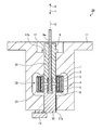
- FIG. 1 is a cross-sectional view of the operating device according to the first embodiment of the present invention.
- the operating device 20 includes a yoke 11 having a hole 17 formed along the operation axis C. Inside the hole 17 of the yoke 11, the fixed iron core 9 and the movable iron core 10 are provided to face each other.
- the movable iron core 10 is provided on the end 17a side of the hole 17 and the fixed iron core 9 is provided on the other end 17b side.
- the fixed iron core 9 is fixed inside the hole 17.
- the movable iron core 10 is movable along the operation axis C inside the hole 17.
- the yoke 11 is provided with a stopper 14 that closes one end 17a of the hole 17 and prevents the movable iron core 10 from falling off.
- an urging portion 13 that applies an urging force in a direction in which the fixed iron core 9 and the movable iron core 10 are separated from each other.
- the biasing portion 13 is, for example, a coil spring.
- a gap is formed between the fixed iron core 9 and the movable iron core 10 by the urging force of the urging portion 13.
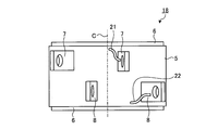
- FIG. 2 is a plan view of the electromagnet 18 in the first embodiment.
- FIG. 3 is a side view of the electromagnet 18 in the first embodiment.
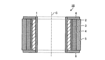
- 4 is a cross-sectional view taken along line AA shown in FIG. 2 to 4 also show the operation axis C of the controller device 20.
- the first coil 2 is provided outside the winding frame 1, and the insulator 3 is provided outside thereof.
- the first coil 2 is formed by winding the conductive first winding 21 shown in FIG.
- the second coil 4 is provided outside the insulator 3.
- the second coil 4 is formed by winding the conductive second winding 22 shown in FIG. 3 around the insulator 3.
- the first coil 2 and the second coil 4 have the same number of turns of the windings 21 and 22, that is, the number of turns of the windings 21 and 22.
- the concept of “the number of turns is the same” in this specification includes a case where there is a slight difference between the number of turns of the first winding 21 and the number of turns of the second winding 22. .
- the wire diameter of the second winding 22 is larger than the wire diameter of the first winding 21.
- the tape 5 is wound around the outside of the second coil 4.
- a first coil terminal 7 and a second coil terminal 8 are fixed to the outside of the tape 5.
- Both end surfaces of the electromagnet 18 in an annular shape are covered with a plate-like end plate 6.
- the end of the first winding 21 is drawn outside from between the insulator 3, the second coil 4, the tape 5, and the end plate 6, and as shown in FIG. It is connected to the.
- the end of the second winding 22 is drawn outward from between the tape 5 and the end plate 6 and connected to the second coil terminal 8 as shown in FIG.
- a power supply line (not shown) is connected to each of the first coil terminal 7 and the second coil terminal 8.
- the first coil terminal 7 and the second coil terminal 8 can be separately energized through a power line. Accordingly, the first coil 2 and the second coil 4 can be energized separately.
- the center position of the electromagnet 18 and the position of the gap between the fixed iron core 9 and the movable iron core 10 coincide with each other. More specifically, in the direction along the operation axis C, the center position of the first coil 2, the center position of the second coil 4, and the position of the gap between the fixed iron core 9 and the movable iron core 10 match. To do.
- a plunger 12 is fixed to a surface of the movable iron core 10 that faces the fixed iron core 9.
- the plunger 12 has a rod shape extending along the operation axis C.
- the fixed iron core 9 is formed with a through hole 9a extending along the operation axis C.
- the plunger 12 passes through the through hole 9 a and protrudes toward the other end 17 b of the hole 17 of the yoke 11.
- an attractive force can be generated between the fixed iron core 9 and the movable iron core 10 by generating a magnetic flux by energizing the first coil 2 or the second coil 4. .
- the movable iron core 10 moves toward the fixed iron core 9 against the urging force of the urging portion 13.
- the plunger 12 fixed to the movable iron core 9 moves in the direction indicated by the arrow X.
- the attractive force between the fixed iron core 9 and the movable iron core 10 disappears.
- the operation lever can be operated by energizing or stopping the first coil 2 or the second coil 4. Become.
- the number of turns of the windings 21 and 22 is the same, and the distance from the operation axis C is greater in the second coil 4 than in the first coil 2.
- the total length of the second winding 22 is longer than the total length of the first winding 21.
- the electrical resistance per unit length is greater than that of the first winding 21.
- the second winding 22 is smaller.
- the total length of the second winding 22 in the second coil 4 is longer than the total length of the first winding 21 in the first coil 2.
- the difference between the electrical resistance of the entire first winding 21 and the resistance of the entire second winding 22 of the second coil 4 is made smaller than when the windings 21 and 22 have the same wire diameter. be able to.
- the generated magnetic flux can be made identical between when the first coil 2 is energized and when the second coil 4 is energized. Therefore, the same suction force generated between the fixed iron core 9 and the movable iron core 10 can be achieved when the first coil 2 is energized and when the second coil 4 is energized. That is, the operating speed of the movable iron core 10 can be made identical between when the first coil 2 is energized and when the second coil 4 is energized.
- the plunger 12 when the plunger 12 is connected to the operation lever of the gas insulated switchgear, it is possible to equalize the time until the operation is completed when the first coil 2 or the second coil 4 is energized.
- the coil that is normally energized is the first coil 2
- the second coil 4 is a backup coil when the first coil 2 cannot be energized.
- the movable iron core 10 can be operated at a speed. As described above, in the operating device 20 according to the first embodiment, the movable iron core 10 can be operated at the same speed regardless of which coil is energized, and the reliability of the product can be improved. it can.
- the center position of the first coil 2, the center position of the second coil 4, and the position of the gap between the fixed iron core 9 and the movable iron core 10 coincide with each other in the direction along the operation axis C.
- the gap between the fixed iron core 9 and the movable iron core 10 can be located in a region where the magnetic flux density is high. Thereby, the attraction force generated by the magnetic flux generated from the first coil 2 or the second coil 4 is maximized.
- FIG. 5 is a cross-sectional view of the electromagnet 18 provided in the operating device according to the modification of the first embodiment.
- a third coil 16 is provided outside the second coil 4.
- the wire diameter of the third winding (not shown) wound as the third coil 16 is set to the second winding.
- the operating speed of the movable iron core 10 is the same when the first coil 2 is energized, when the second coil 4 is energized, and when the third coil 16 is energized. Can be achieved. Further, since the number of backup coils is increased, the reliability of the product can be further improved.
- the number of coils is not limited to three shown as a modification, and may be four or more. That is, the reliability of the product can be further improved by providing multiple coils around the operation axis C and increasing the wire diameter of the winding wound around the outer coil.
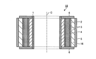
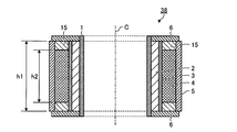
- FIG. FIG. 6 is a cross-sectional view of an electromagnet provided in the operating device according to the second embodiment of the present invention.
- symbol is attached
- the length h ⁇ b> 2 of the second coil 4 is shorter than the length h ⁇ b> 1 of the first coil 2 in the direction along the operation axis C. More specifically, the relationship 1 ⁇ h1 / h2 ⁇ 1.3 is satisfied.
- An insulator 15 is provided in the gap between the end plate 6 and the second coil 4. In the direction along the operation axis C, the center position of the first coil 2 and the center position of the second coil 4 are matched.
- the electromagnet 38 can be reduced in size. As the electromagnet 38 is downsized, the operating device can be downsized.
- FIG. 7 is a cross-sectional view of the electromagnet provided in the operating device according to the third embodiment of the present invention.
- symbol is attached
- the length h1 of the first coil 2 is shorter than the length h2 of the second coil 4 in the direction along the operation axis C. More specifically, the relationship of 0.7 ⁇ h1 / h2 ⁇ 1 is satisfied.
- An insulator 15 is provided in the gap between the end plate 6 and the first coil 2. In the direction along the operation axis C, the center position of the first coil 2 and the center position of the second coil 4 are matched.
- the configuration described in the above embodiment shows an example of the contents of the present invention, and can be combined with another known technique, and can be combined with other configurations without departing from the gist of the present invention. It is also possible to omit or change the part.
Abstract
The operation device (20) is equipped with: a movable core (10) which can be moved back and forth along an operating axis (C); a stationary core (9) which is disposed on the operating axis (C) and faces the movable core (10); a first coil (2) which is made of a first winding wound into a cylindrical shape about the operating axis (C); and a second coil (4) which is made of a second winding wound into a cylindrical shape about the operating axis (C) on the outside of the first coil (2). In addition, the wire diameter of the second winding is larger than that of the first winding.
Description
本発明は、コイルに発生した磁束で可動鉄心を動作させる操作装置に関するものである。
The present invention relates to an operating device for operating a movable iron core with a magnetic flux generated in a coil.
従来、コイルに通電することで発生した磁束によって、可動鉄心を動作させる操作装置が用いられている。特許文献1には、二重にコイルを設けた操作装置が開示されている。
Conventionally, an operating device that moves a movable iron core by magnetic flux generated by energizing a coil has been used. Patent Document 1 discloses an operating device provided with double coils.
上記特許文献1に開示された構成では、可動鉄心を動作させる際に通電されるのは内側のコイルであり、外側のコイルには小電流を長時間流して投入保持用のコイルとしている。このように、内側のコイルと外側のコイルとで使用目的が異なるため、内側のコイルに通電した場合と、外側のコイルに通電した場合とで、発生する磁束が異なる。そのため、外側のコイルに通電して可動鉄心を動作させようとしても、その動作速度は、内側のコイルに通電した際の可動鉄心の動作速度とは異なってしまう。
In the configuration disclosed in Patent Document 1, the inner coil is energized when the movable iron core is operated, and a small current is allowed to flow through the outer coil for a long time to serve as a holding coil. As described above, since the purpose of use is different between the inner coil and the outer coil, the generated magnetic flux differs between when the inner coil is energized and when the outer coil is energized. Therefore, even if it is attempted to operate the movable iron core by energizing the outer coil, the operation speed is different from the operation speed of the movable iron core when the inner coil is energized.
したがって、内側のコイルに通電した場合と、外側のコイルに通電した場合のどちらの場合であっても可動鉄心を同じように動作させて、一方のコイルへの通電系統に異常があった場合でも、他方のコイルに通電することで可動鉄心を動作させるようにして、操作装置の信頼性の向上を図ることが難しい。
Therefore, even if the inner coil is energized or the outer coil is energized, the movable iron core is operated in the same way, even if there is an abnormality in the energization system to one coil. It is difficult to improve the reliability of the operating device by operating the movable iron core by energizing the other coil.
本発明は、上記に鑑みてなされたものであって、多重に設けられたコイルのいずれのコイルに通電した場合であっても同じ速度で可動鉄心を動作させることを可能とすることで、製品の信頼性の向上を図ることのできる操作装置を得ることを目的とする。
The present invention has been made in view of the above, and it is possible to operate a movable iron core at the same speed even when any coil of multiple coils is energized. An object of the present invention is to obtain an operating device capable of improving the reliability of the apparatus.
上述した課題を解決し、目的を達成するために、本発明は、動作軸に沿って往復移動可能とされた可動鉄心と、動作軸上に設けられて可動鉄心と対向する固定鉄心と、動作軸を中心とする円筒形状に巻き付けられた第1の巻線で構成される第1のコイルと、動作軸を中心とする円筒形状で第1のコイルの外側に巻き付けられた第2の巻線で構成される第2のコイルと、を備える。また、第1の巻線の線径よりも第2の巻線の線径のほうが大きい。
In order to solve the above-described problems and achieve the object, the present invention provides a movable iron core that can be reciprocated along an operation axis, a fixed iron core that is provided on the operation axis and faces the movable iron core, and an operation A first coil composed of a first winding wound in a cylindrical shape centered on an axis, and a second coil wound around the outside of the first coil in a cylindrical shape centered on an operating axis The 2nd coil comprised by these. Further, the wire diameter of the second winding is larger than the wire diameter of the first winding.
本発明にかかる操作装置によれば、多重に設けられたコイルのいずれのコイルに通電した場合であっても同じ速度で可動鉄心を動作させることを可能とすることで、製品の信頼性の向上を図ることができるという効果を奏する。
According to the operating device according to the present invention, it is possible to operate the movable iron core at the same speed regardless of which of the multiple coils is energized, thereby improving the reliability of the product. There is an effect that can be achieved.
以下に、本発明の実施の形態にかかる操作装置を図面に基づいて詳細に説明する。なお、この実施の形態によりこの発明が限定されるものではない。
Hereinafter, an operating device according to an embodiment of the present invention will be described in detail with reference to the drawings. Note that the present invention is not limited to the embodiments.
実施の形態1.
図1は、本発明の実施の形態1にかかる操作装置の断面図である。操作装置20は、動作軸Cに沿って穴17が形成された継鉄11を備える。継鉄11の穴17の内部には、固定鉄心9と可動鉄心10とが互いに対向して設けられる。穴17の端部のうち一端部17a側に可動鉄心10が設けられ、他端部17b側に固定鉄心9が設けられる。Embodiment 1 FIG.
FIG. 1 is a cross-sectional view of the operating device according to the first embodiment of the present invention. Theoperating device 20 includes a yoke 11 having a hole 17 formed along the operation axis C. Inside the hole 17 of the yoke 11, the fixed iron core 9 and the movable iron core 10 are provided to face each other. The movable iron core 10 is provided on the end 17a side of the hole 17 and the fixed iron core 9 is provided on the other end 17b side.
図1は、本発明の実施の形態1にかかる操作装置の断面図である。操作装置20は、動作軸Cに沿って穴17が形成された継鉄11を備える。継鉄11の穴17の内部には、固定鉄心9と可動鉄心10とが互いに対向して設けられる。穴17の端部のうち一端部17a側に可動鉄心10が設けられ、他端部17b側に固定鉄心9が設けられる。
FIG. 1 is a cross-sectional view of the operating device according to the first embodiment of the present invention. The
固定鉄心9は、穴17の内部に固定されている。可動鉄心10は、穴17の内部で動作軸Cに沿って移動可能とされる。継鉄11には、穴17の一端部17aを塞いで、可動鉄心10の抜け落ちを防ぐストッパ14が設けられている。
The fixed iron core 9 is fixed inside the hole 17. The movable iron core 10 is movable along the operation axis C inside the hole 17. The yoke 11 is provided with a stopper 14 that closes one end 17a of the hole 17 and prevents the movable iron core 10 from falling off.
固定鉄心9と可動鉄心10との間には、固定鉄心9と可動鉄心10とを離間させる方向に付勢力を付与する付勢部13が設けられている。付勢部13は、例えばコイルばねである。付勢部13の付勢力によって、固定鉄心9と可動鉄心10との間には隙間が形成される。
Between the fixed iron core 9 and the movable iron core 10, there is provided an urging portion 13 that applies an urging force in a direction in which the fixed iron core 9 and the movable iron core 10 are separated from each other. The biasing portion 13 is, for example, a coil spring. A gap is formed between the fixed iron core 9 and the movable iron core 10 by the urging force of the urging portion 13.
穴17の内部には、電磁石18が設けられる。電磁石18は、動作軸Cを中心とする円筒形状である。図2は、実施の形態1における電磁石18の平面図である。図3は、実施の形態1における電磁石18の側面図である。図4は、図2に示すA-A線に沿った矢視断面図である。なお、図2から図4では、操作装置20の動作軸Cも示している。
An electromagnet 18 is provided inside the hole 17. The electromagnet 18 has a cylindrical shape with the operation axis C as the center. FIG. 2 is a plan view of the electromagnet 18 in the first embodiment. FIG. 3 is a side view of the electromagnet 18 in the first embodiment. 4 is a cross-sectional view taken along line AA shown in FIG. 2 to 4 also show the operation axis C of the controller device 20.
電磁石18では、巻枠1の外側に第1のコイル2が設けられ、その外側に絶縁物3が設けられる。第1のコイル2は、図3に示す導電性の第1の巻線21を巻枠1に巻き付けることで形成される。また、電磁石18では、絶縁物3の外側に第2のコイル4が設けられる。第2のコイル4は、図3に示す導電性の第2の巻線22を絶縁物3に巻き付けることで形成される。
In the electromagnet 18, the first coil 2 is provided outside the winding frame 1, and the insulator 3 is provided outside thereof. The first coil 2 is formed by winding the conductive first winding 21 shown in FIG. In the electromagnet 18, the second coil 4 is provided outside the insulator 3. The second coil 4 is formed by winding the conductive second winding 22 shown in FIG. 3 around the insulator 3.
第1のコイル2と第2のコイル4は、巻線21,22のターン数、すなわち巻線21,22の巻き数が同じとなっている。なお、本明細書の中での「巻き数が同じ」の概念には、第1の巻線21の巻き数と第2の巻線22の巻き数との多少の違いがある場合が含まれる。例えば、第1のコイル2における第1の巻線21の巻き数をr1とし、第2のコイル4における第2の巻線22の巻き数をr2とした場合に、0.8<r1/r2<1.2の関係を満たすものも、「巻き数が同じ」の概念に含まれる。また、第1の巻線21の線径よりも第2の巻線22の線径のほうが大きくなっている。
The first coil 2 and the second coil 4 have the same number of turns of the windings 21 and 22, that is, the number of turns of the windings 21 and 22. The concept of “the number of turns is the same” in this specification includes a case where there is a slight difference between the number of turns of the first winding 21 and the number of turns of the second winding 22. . For example, when the number of turns of the first winding 21 in the first coil 2 is r1, and the number of turns of the second winding 22 in the second coil 4 is r2, 0.8 <r1 / r2 Those satisfying the relationship <1.2 are also included in the concept of “the same number of turns”. Further, the wire diameter of the second winding 22 is larger than the wire diameter of the first winding 21.
第2のコイル4の外側には、テープ5が巻き付けられる。テープ5の外側には、第1のコイル端子7と第2のコイル端子8が固定される。電磁石18の円環形状の両端面は板状の端板6で覆われる。第1の巻線21の端部は、絶縁物3、第2のコイル4およびテープ5と、端板6との間から外側に引き出されて、図3に示すように第1のコイル端子7に接続されている。また、第2の巻線22の端部は、テープ5と端板6との間から外側に引き出されて、図3に示すように第2のコイル端子8に接続される。
The tape 5 is wound around the outside of the second coil 4. A first coil terminal 7 and a second coil terminal 8 are fixed to the outside of the tape 5. Both end surfaces of the electromagnet 18 in an annular shape are covered with a plate-like end plate 6. The end of the first winding 21 is drawn outside from between the insulator 3, the second coil 4, the tape 5, and the end plate 6, and as shown in FIG. It is connected to the. Further, the end of the second winding 22 is drawn outward from between the tape 5 and the end plate 6 and connected to the second coil terminal 8 as shown in FIG.
第1のコイル端子7と第2のコイル端子8のそれぞれには、図示を省略した電源線が接続される。また、第1のコイル端子7と第2のコイル端子8には、電源線を通して別個に通電可能とされている。したがって、第1のコイル2と第2のコイル4には、それぞれ別個に通電することができる。
A power supply line (not shown) is connected to each of the first coil terminal 7 and the second coil terminal 8. The first coil terminal 7 and the second coil terminal 8 can be separately energized through a power line. Accordingly, the first coil 2 and the second coil 4 can be energized separately.
図1に戻って、動作軸Cに沿った方向において、電磁石18の中心位置と、固定鉄心9と可動鉄心10との隙間の位置とが一致する。より具体的には、動作軸Cに沿った方向において、第1のコイル2の中心位置と、第2のコイル4の中心位置と、固定鉄心9と可動鉄心10との隙間の位置とが一致する。
1, in the direction along the operation axis C, the center position of the electromagnet 18 and the position of the gap between the fixed iron core 9 and the movable iron core 10 coincide with each other. More specifically, in the direction along the operation axis C, the center position of the first coil 2, the center position of the second coil 4, and the position of the gap between the fixed iron core 9 and the movable iron core 10 match. To do.
可動鉄心10のうち、固定鉄心9と対向する面には、プランジャ12が固定されている。プランジャ12は、動作軸Cに沿って延びる棒状形状を呈している。また、固定鉄心9には、動作軸Cに沿って延びる貫通穴9aが形成されている。プランジャ12は、貫通穴9aを貫通し、継鉄11の穴17の他端部17b側に突出している。
A plunger 12 is fixed to a surface of the movable iron core 10 that faces the fixed iron core 9. The plunger 12 has a rod shape extending along the operation axis C. The fixed iron core 9 is formed with a through hole 9a extending along the operation axis C. The plunger 12 passes through the through hole 9 a and protrudes toward the other end 17 b of the hole 17 of the yoke 11.
上述した操作装置20によれば、第1のコイル2または第2のコイル4に通電して磁束を発生させることで、固定鉄心9と可動鉄心10との間に吸引力を発生させることができる。固定鉄心9と可動鉄心10との間に吸引力が発生することで、付勢部13の付勢力に抗して可動鉄心10が固定鉄心9側に移動する。これにより、可動鉄心9に固定されたプランジャ12が矢印Xに示す方向に移動する。また、第1のコイル2または第2のコイル4への通電を停止することで、固定鉄心9と可動鉄心10との間の吸引力が消失する。固定鉄心9と可動鉄心10との間の吸引力が消失することで、付勢部13の付勢力によって可動鉄心10が固定鉄心9から離間する方向に移動する。これにより、可動鉄心10に固定されたプランジャ12が矢印Yに示す方向に移動する。
According to the operation device 20 described above, an attractive force can be generated between the fixed iron core 9 and the movable iron core 10 by generating a magnetic flux by energizing the first coil 2 or the second coil 4. . By generating a suction force between the fixed iron core 9 and the movable iron core 10, the movable iron core 10 moves toward the fixed iron core 9 against the urging force of the urging portion 13. As a result, the plunger 12 fixed to the movable iron core 9 moves in the direction indicated by the arrow X. Further, by stopping energization to the first coil 2 or the second coil 4, the attractive force between the fixed iron core 9 and the movable iron core 10 disappears. When the attractive force between the fixed iron core 9 and the movable iron core 10 disappears, the movable iron core 10 moves away from the fixed iron core 9 by the urging force of the urging portion 13. As a result, the plunger 12 fixed to the movable iron core 10 moves in the direction indicated by the arrow Y.
プランジャ12の先端に、例えばガス絶縁開閉装置の操作レバーを連結すれば、第1のコイル2または第2のコイル4への通電またはその停止を行うことで、操作レバーを操作することが可能となる。
If, for example, an operation lever of a gas insulated switchgear is connected to the tip of the plunger 12, the operation lever can be operated by energizing or stopping the first coil 2 or the second coil 4. Become.
本実施の形態1にかかる操作装置20では、巻線21,22の巻き数が同じであり、動作軸Cからの距離が第1のコイル2よりも第2のコイル4のほうが離れているため、第1の巻線21の全長よりも第2の巻線22の全長のほうが長くなる。
In the operating device 20 according to the first embodiment, the number of turns of the windings 21 and 22 is the same, and the distance from the operation axis C is greater in the second coil 4 than in the first coil 2. The total length of the second winding 22 is longer than the total length of the first winding 21.
また、操作装置20では、第2の巻線22の線径を第1の巻線21の線径よりも大きくしているため、単位長さあたりの電気抵抗は、第1の巻線21よりも第2の巻線22のほうが小さくなる。
In the operating device 20, since the wire diameter of the second winding 22 is larger than the wire diameter of the first winding 21, the electrical resistance per unit length is greater than that of the first winding 21. However, the second winding 22 is smaller.
したがって、操作装置20では、第1のコイル2における第1の巻線21の全長よりも、第2のコイル4における第2の巻線22の全長が長くなっているが、第1のコイル2における第1の巻線21全体の電気抵抗と、第2のコイル4における第2の巻線22全体の抵抗との差は、巻線21,22を同じ線径とした場合に比べて小さくすることができる。
Therefore, in the operating device 20, the total length of the second winding 22 in the second coil 4 is longer than the total length of the first winding 21 in the first coil 2. The difference between the electrical resistance of the entire first winding 21 and the resistance of the entire second winding 22 of the second coil 4 is made smaller than when the windings 21 and 22 have the same wire diameter. be able to.
これにより、第1のコイル2に通電した場合と、第2のコイル4に通電した場合とで、発生する磁束の同一化を図ることができる。したがって、第1のコイル2に通電した場合と、第2のコイル4に通電した場合とで、固定鉄心9と可動鉄心10の間に発生する吸引力の同一化が図られる。すなわち、第1のコイル2に通電した場合と、第2のコイル4に通電した場合とで、可動鉄心10の動作速度の同一化を図ることができる。
Thereby, the generated magnetic flux can be made identical between when the first coil 2 is energized and when the second coil 4 is energized. Therefore, the same suction force generated between the fixed iron core 9 and the movable iron core 10 can be achieved when the first coil 2 is energized and when the second coil 4 is energized. That is, the operating speed of the movable iron core 10 can be made identical between when the first coil 2 is energized and when the second coil 4 is energized.
例えば、プランジャ12をガス絶縁開閉装置の操作レバーに連結した場合には、第1のコイル2または第2のコイル4に通電した際の、操作完了までの時間の同一化を図ることができる。ここで、通常時に通電するコイルを第1のコイル2とし、第2のコイル4は第1のコイル2に通電できない場合のバックアップ用のコイルとしている場合を考える。このような場合に、何らかの理由によって第1のコイル2に通電することができなくなった場合であっても、第2のコイル4に通電すれば、第1のコイル2に通電した場合と同様の速度で可動鉄心10を動作させることができる。このように、本実施の形態1にかかる操作装置20では、いずれのコイルに通電した場合であっても同じ速度で可動鉄心10を動作させることができ、製品の信頼性の向上を図ることができる。
For example, when the plunger 12 is connected to the operation lever of the gas insulated switchgear, it is possible to equalize the time until the operation is completed when the first coil 2 or the second coil 4 is energized. Here, let us consider a case where the coil that is normally energized is the first coil 2, and the second coil 4 is a backup coil when the first coil 2 cannot be energized. In such a case, even if the first coil 2 cannot be energized for some reason, if the second coil 4 is energized, it is the same as the case where the first coil 2 is energized. The movable iron core 10 can be operated at a speed. As described above, in the operating device 20 according to the first embodiment, the movable iron core 10 can be operated at the same speed regardless of which coil is energized, and the reliability of the product can be improved. it can.
また、動作軸Cに沿った方向において、第1のコイル2の中心位置と、第2のコイル4の中心位置と、固定鉄心9と可動鉄心10との隙間の位置とが一致しているので、磁束密度が高い領域に固定鉄心9と可動鉄心10との隙間を位置させることができる。これにより、第1のコイル2または第2のコイル4から発生する磁束によって発生する吸引力の最大化が図られる。
Further, since the center position of the first coil 2, the center position of the second coil 4, and the position of the gap between the fixed iron core 9 and the movable iron core 10 coincide with each other in the direction along the operation axis C. The gap between the fixed iron core 9 and the movable iron core 10 can be located in a region where the magnetic flux density is high. Thereby, the attraction force generated by the magnetic flux generated from the first coil 2 or the second coil 4 is maximized.
図5は、実施の形態1の変形例にかかる操作装置が備える電磁石18の断面図である。本変形例では、第2のコイル4の外側に、第3のコイル16が設けられている。このように、コイル2,4,16を三重に設けた場合であっても、第3のコイル16として巻き付けられた第3の巻線(図示せず)の線径を、第2の巻線22よりも大きくすることで、第1のコイル2に通電した場合と、第2のコイル4に通電した場合と、第3のコイル16に通電した場合とで、可動鉄心10の動作速度の同一化を図ることができる。また、バックアップ用のコイルが増えることで、製品のより一層の信頼性の向上を図ることができる。なお、コイルの数は変形例として示した3つに限られず、4つ以上であっても構わない。すなわち、動作軸Cを中心として多重にコイルを設け、より外側のコイルに巻き付けられる巻線の線径を大きくすることで、より一層の製品の信頼性の向上を図ることができる。
FIG. 5 is a cross-sectional view of the electromagnet 18 provided in the operating device according to the modification of the first embodiment. In the present modification, a third coil 16 is provided outside the second coil 4. Thus, even when the coils 2, 4 and 16 are provided in triplicate, the wire diameter of the third winding (not shown) wound as the third coil 16 is set to the second winding. By making it larger than 22, the operating speed of the movable iron core 10 is the same when the first coil 2 is energized, when the second coil 4 is energized, and when the third coil 16 is energized. Can be achieved. Further, since the number of backup coils is increased, the reliability of the product can be further improved. Note that the number of coils is not limited to three shown as a modification, and may be four or more. That is, the reliability of the product can be further improved by providing multiple coils around the operation axis C and increasing the wire diameter of the winding wound around the outer coil.
実施の形態2.
図6は、本発明の実施の形態2にかかる操作装置が備える電磁石の断面図である。なお、上記実施の形態と同様の構成については、同様の符号を付して詳細な説明を省略する。電磁石38では、動作軸Cに沿った方向において、第1のコイル2の長さh1よりも第2のコイル4の長さh2のほうが短くなっている。より具体的には、1<h1/h2<1.3の関係を満たす。端板6と第2のコイル4との隙間には絶縁物15が設けられる。また、動作軸Cに沿った方向において、第1のコイル2の中心位置と第2のコイル4の中心位置を一致させている。Embodiment 2. FIG.
FIG. 6 is a cross-sectional view of an electromagnet provided in the operating device according to the second embodiment of the present invention. In addition, about the structure similar to the said embodiment, the same code | symbol is attached | subjected and detailed description is abbreviate | omitted. In theelectromagnet 38, the length h <b> 2 of the second coil 4 is shorter than the length h <b> 1 of the first coil 2 in the direction along the operation axis C. More specifically, the relationship 1 <h1 / h2 <1.3 is satisfied. An insulator 15 is provided in the gap between the end plate 6 and the second coil 4. In the direction along the operation axis C, the center position of the first coil 2 and the center position of the second coil 4 are matched.
図6は、本発明の実施の形態2にかかる操作装置が備える電磁石の断面図である。なお、上記実施の形態と同様の構成については、同様の符号を付して詳細な説明を省略する。電磁石38では、動作軸Cに沿った方向において、第1のコイル2の長さh1よりも第2のコイル4の長さh2のほうが短くなっている。より具体的には、1<h1/h2<1.3の関係を満たす。端板6と第2のコイル4との隙間には絶縁物15が設けられる。また、動作軸Cに沿った方向において、第1のコイル2の中心位置と第2のコイル4の中心位置を一致させている。
FIG. 6 is a cross-sectional view of an electromagnet provided in the operating device according to the second embodiment of the present invention. In addition, about the structure similar to the said embodiment, the same code | symbol is attached | subjected and detailed description is abbreviate | omitted. In the
本実施の形態2では、第1のコイル端子7に接続する第1の巻線21(図2も参照)を端板6と第2のコイル4との隙間に通すことができるので、作業性が向上する。また、第1のコイル端子7および第2のコイル端子8の一部を絶縁物15に埋め込むことで、電磁石38の小型化を図ることができる。そして、電磁石38の小型化に伴い、操作装置の小型化を図ることができる。
In the second embodiment, since the first winding 21 (see also FIG. 2) connected to the first coil terminal 7 can be passed through the gap between the end plate 6 and the second coil 4, workability is improved. Will improve. Further, by embedding part of the first coil terminal 7 and the second coil terminal 8 in the insulator 15, the electromagnet 38 can be reduced in size. As the electromagnet 38 is downsized, the operating device can be downsized.
実施の形態3.
図7は、本発明の実施の形態3にかかる操作装置が備える電磁石の断面図である。なお、上記実施の形態と同様の構成については、同様の符号を付して詳細な説明を省略する。電磁石48では、動作軸Cに沿った方向において、第2のコイル4の長さh2よりも第1のコイル2の長さh1のほうが短くなっている。より具体的には、0.7<h1/h2<1の関係を満たす。端板6と第1のコイル2との隙間には絶縁物15が設けられる。また、動作軸Cに沿った方向において、第1のコイル2の中心位置と第2のコイル4の中心位置を一致させている。Embodiment 3 FIG.
FIG. 7 is a cross-sectional view of the electromagnet provided in the operating device according to the third embodiment of the present invention. In addition, about the structure similar to the said embodiment, the same code | symbol is attached | subjected and detailed description is abbreviate | omitted. In theelectromagnet 48, the length h1 of the first coil 2 is shorter than the length h2 of the second coil 4 in the direction along the operation axis C. More specifically, the relationship of 0.7 <h1 / h2 <1 is satisfied. An insulator 15 is provided in the gap between the end plate 6 and the first coil 2. In the direction along the operation axis C, the center position of the first coil 2 and the center position of the second coil 4 are matched.
図7は、本発明の実施の形態3にかかる操作装置が備える電磁石の断面図である。なお、上記実施の形態と同様の構成については、同様の符号を付して詳細な説明を省略する。電磁石48では、動作軸Cに沿った方向において、第2のコイル4の長さh2よりも第1のコイル2の長さh1のほうが短くなっている。より具体的には、0.7<h1/h2<1の関係を満たす。端板6と第1のコイル2との隙間には絶縁物15が設けられる。また、動作軸Cに沿った方向において、第1のコイル2の中心位置と第2のコイル4の中心位置を一致させている。
FIG. 7 is a cross-sectional view of the electromagnet provided in the operating device according to the third embodiment of the present invention. In addition, about the structure similar to the said embodiment, the same code | symbol is attached | subjected and detailed description is abbreviate | omitted. In the
以上の実施の形態に示した構成は、本発明の内容の一例を示すものであり、別の公知の技術と組み合わせることも可能であるし、本発明の要旨を逸脱しない範囲で、構成の一部を省略、変更することも可能である。
The configuration described in the above embodiment shows an example of the contents of the present invention, and can be combined with another known technique, and can be combined with other configurations without departing from the gist of the present invention. It is also possible to omit or change the part.
1 巻枠、2 第1のコイル、3 絶縁物、4 第2のコイル、5 テープ、6 端板、7 第1のコイル端子、8 第2のコイル端子、9 固定鉄心、9a 貫通穴、10 可動鉄心、11 継鉄、12 プランジャ、13 付勢部、14 ストッパ、15 絶縁物、16 第3のコイル、17 穴、17a 一端部、17b 他端部、18,38,48 電磁石、20 操作装置、21 第1の巻線、22 第2の巻線。
1 reel, 2 first coil, 3 insulator, 4 second coil, 5 tape, 6 end plate, 7 first coil terminal, 8 second coil terminal, 9 fixed core, 9a through hole, 10 Movable iron core, 11 yoke, 12 plunger, 13 biasing part, 14 stopper, 15 insulator, 16 third coil, 17 hole, 17a one end, 17b other end, 18, 38, 48 electromagnet, 20 operation device , 21 1st winding, 22 2nd winding.
Claims (8)
- 動作軸に沿って往復移動可能とされた可動鉄心と、
前記動作軸上に設けられて前記可動鉄心と対向する固定鉄心と、
前記動作軸を中心とする円筒形状に巻き付けられた第1の巻線で構成される第1のコイルと、
前記動作軸を中心とする円筒形状で前記第1のコイルの外側に巻き付けられた第2の巻線で構成される第2のコイルと、を備え、
前記第1の巻線の線径よりも前記第2の巻線の線径のほうが大きいことを特徴とする操作装置。 A movable iron core capable of reciprocating along the movement axis;
A fixed iron core provided on the operating axis and facing the movable iron core;
A first coil composed of a first winding wound in a cylindrical shape centering on the operating axis;
A second coil composed of a second winding wound around the outside of the first coil in a cylindrical shape centered on the operation axis,
The operating device characterized in that the wire diameter of the second winding is larger than the wire diameter of the first winding. - 前記動作軸に沿った方向において、前記第1のコイルの中心位置と、前記第2のコイルの中心位置と、前記可動鉄心と前記固定鉄心との隙間の位置とが一致することを特徴とする請求項1に記載の操作装置。 The center position of the first coil, the center position of the second coil, and the position of the gap between the movable iron core and the fixed iron core coincide with each other in the direction along the operation axis. The operating device according to claim 1.
- 前記動作軸に沿った方向において、前記第1のコイルの長さよりも前記第2のコイルの長さのほうが短いことを特徴とする請求項1に記載の操作装置。 The operating device according to claim 1, wherein a length of the second coil is shorter than a length of the first coil in a direction along the operation axis.
- 前記動作軸に沿った方向において、前記第1のコイルの長さをh1とし、前記第2のコイルの長さをh2とした場合に、1<h1/h2<1.3の関係を満たすことを特徴とする請求項3に記載の操作装置。 When the length of the first coil is h1 and the length of the second coil is h2 in the direction along the operation axis, the relationship 1 <h1 / h2 <1.3 is satisfied. The operating device according to claim 3.
- 前記動作軸に沿った方向において、前記第2のコイルの長さよりも前記第1のコイルの長さのほうが短いことを特徴とする請求項1に記載の操作装置。 The operating device according to claim 1, wherein a length of the first coil is shorter than a length of the second coil in a direction along the operation axis.
- 前記動作軸に沿った方向において、前記第1のコイルの長さをh1とし、前記第2のコイルの長さをh2とした場合に、0.7<h1/h2<1の関係を満たすことを特徴とする請求項5に記載の操作装置。 When the length of the first coil is h1 and the length of the second coil is h2 in the direction along the operation axis, the relationship of 0.7 <h1 / h2 <1 is satisfied. The operating device according to claim 5.
- 前記第1のコイルにおける前記第1の巻線の巻き数をr1とし、前記第2のコイルにおける前記第2の巻線の巻き数をr2とした場合に、0.8<r1/r2<1.2の関係を満たすことを特徴とする請求項1に記載の操作装置。 When the number of turns of the first winding in the first coil is r1 and the number of turns of the second winding in the second coil is r2, 0.8 <r1 / r2 <1 The operating device according to claim 1, wherein the relationship of .2 is satisfied.
- 前記動作軸を中心とする円筒形状で前記第2のコイルの外側に巻き付けられた第3の巻線で構成される第3のコイルをさらに備え、
前記第2の巻線の線径よりも前記第3の巻線の線径のほうが大きいことを特徴とする請求項1に記載の操作装置。 A third coil composed of a third winding wound around the outside of the second coil in a cylindrical shape centered on the operation axis;
The operating device according to claim 1, wherein a wire diameter of the third winding is larger than a wire diameter of the second winding.
Priority Applications (3)
| Application Number | Priority Date | Filing Date | Title |
|---|---|---|---|
| PCT/JP2016/059680 WO2017163411A1 (en) | 2016-03-25 | 2016-03-25 | Operation device |
| JP2016558162A JP6104478B1 (en) | 2016-03-25 | 2016-03-25 | Operating device |
| US16/079,505 US20190051480A1 (en) | 2016-03-25 | 2016-03-25 | Operating device |
Applications Claiming Priority (1)
| Application Number | Priority Date | Filing Date | Title |
|---|---|---|---|
| PCT/JP2016/059680 WO2017163411A1 (en) | 2016-03-25 | 2016-03-25 | Operation device |
Publications (1)
| Publication Number | Publication Date |
|---|---|
| WO2017163411A1 true WO2017163411A1 (en) | 2017-09-28 |
Family
ID=59366076
Family Applications (1)
| Application Number | Title | Priority Date | Filing Date |
|---|---|---|---|
| PCT/JP2016/059680 WO2017163411A1 (en) | 2016-03-25 | 2016-03-25 | Operation device |
Country Status (3)
| Country | Link |
|---|---|
| US (1) | US20190051480A1 (en) |
| JP (1) | JP6104478B1 (en) |
| WO (1) | WO2017163411A1 (en) |
Citations (6)
| Publication number | Priority date | Publication date | Assignee | Title |
|---|---|---|---|---|
| JPH0357203A (en) * | 1989-07-25 | 1991-03-12 | Matsushita Electric Works Ltd | Electromagnetic apparatus and electromagnetic switch |
| JPH073809Y2 (en) * | 1984-09-08 | 1995-01-30 | 株式会社東芝 | Lead wire connection device for rotating electric machine stator |
| JP2006108041A (en) * | 2004-10-08 | 2006-04-20 | Matsushita Electric Works Ltd | Electromagnetic switching device |
| JP2008010167A (en) * | 2006-06-27 | 2008-01-17 | Matsushita Electric Works Ltd | Electromagnetic switch device |
| WO2012176505A1 (en) * | 2011-06-20 | 2012-12-27 | 日産自動車株式会社 | Electromagnetic relay |
| JP2013089516A (en) * | 2011-10-20 | 2013-05-13 | Mitsubishi Electric Corp | Electromagnetic operation device |
Family Cites Families (8)
| Publication number | Priority date | Publication date | Assignee | Title |
|---|---|---|---|---|
| DE1279182B (en) * | 1965-09-11 | 1968-10-03 | Siemens Ag | Superconducting coil |
| JP4569547B2 (en) * | 2006-02-23 | 2010-10-27 | 株式会社デンソー | Electromagnetic switch |
| DE102007014764A1 (en) * | 2007-03-28 | 2008-06-12 | Robert Bosch Gmbh | Solenoid switch for starters of internal combustion engines, has relay housing, which has relay cover of plastic at front side, in which relay connections are intended |
| JP5488238B2 (en) * | 2010-06-17 | 2014-05-14 | 日産自動車株式会社 | Electromagnetic relay |
| JP5445435B2 (en) * | 2010-12-08 | 2014-03-19 | 三菱電機株式会社 | Electromagnetic vacuum breaker |
| US9324486B2 (en) * | 2013-06-17 | 2016-04-26 | Massachusetts Institute Of Technology | Partial insulation superconducting magnet |
| JP6300157B2 (en) * | 2013-08-02 | 2018-03-28 | パナソニックIpマネジメント株式会社 | Electromagnetic relay |
| CN204067247U (en) * | 2014-06-26 | 2014-12-31 | 德昌电机(深圳)有限公司 | Starter and electromagnetic switch thereof |
-
2016
- 2016-03-25 US US16/079,505 patent/US20190051480A1/en not_active Abandoned
- 2016-03-25 WO PCT/JP2016/059680 patent/WO2017163411A1/en active Application Filing
- 2016-03-25 JP JP2016558162A patent/JP6104478B1/en active Active
Patent Citations (6)
| Publication number | Priority date | Publication date | Assignee | Title |
|---|---|---|---|---|
| JPH073809Y2 (en) * | 1984-09-08 | 1995-01-30 | 株式会社東芝 | Lead wire connection device for rotating electric machine stator |
| JPH0357203A (en) * | 1989-07-25 | 1991-03-12 | Matsushita Electric Works Ltd | Electromagnetic apparatus and electromagnetic switch |
| JP2006108041A (en) * | 2004-10-08 | 2006-04-20 | Matsushita Electric Works Ltd | Electromagnetic switching device |
| JP2008010167A (en) * | 2006-06-27 | 2008-01-17 | Matsushita Electric Works Ltd | Electromagnetic switch device |
| WO2012176505A1 (en) * | 2011-06-20 | 2012-12-27 | 日産自動車株式会社 | Electromagnetic relay |
| JP2013089516A (en) * | 2011-10-20 | 2013-05-13 | Mitsubishi Electric Corp | Electromagnetic operation device |
Also Published As
| Publication number | Publication date |
|---|---|
| JPWO2017163411A1 (en) | 2018-04-12 |
| JP6104478B1 (en) | 2017-03-29 |
| US20190051480A1 (en) | 2019-02-14 |
Similar Documents
| Publication | Publication Date | Title |
|---|---|---|
| JP6300157B2 (en) | Electromagnetic relay | |
| JP5205008B2 (en) | Flat electromagnetic actuator | |
| JP2008237004A5 (en) | ||
| JP6642485B2 (en) | Electromagnetic relay | |
| JP5965451B2 (en) | High speed solenoid | |
| KR20170009983A (en) | Solenoid robust against misalignment of pole piece and flux sleeve | |
| EP3425648B1 (en) | Solenoid | |
| JP2018142529A (en) | Electromagnetic relay | |
| US7420300B2 (en) | Voice coil motor | |
| JP2006234004A (en) | Solenoid valve and method of producing the same | |
| JP6104478B1 (en) | Operating device | |
| JP2016143623A (en) | Electromagnetic relay | |
| JP5659625B2 (en) | Solenoid device | |
| EP3642855B1 (en) | Electromagnetic system | |
| KR101552573B1 (en) | High speed solenoid | |
| JP4829097B2 (en) | Electromagnetic actuator | |
| JP2012019613A (en) | Linear motor | |
| JP5627475B2 (en) | Switch operating mechanism | |
| US20170140861A1 (en) | Constant force, short-stroke electromagnetic actuator | |
| JP6554492B2 (en) | solenoid | |
| JP2018142501A (en) | Electromagnetic relay | |
| JP5696403B2 (en) | Linear actuator | |
| US20140375402A1 (en) | Linear solenoid | |
| JP2014239239A (en) | Electromagnetic solenoid | |
| JP2022102006A (en) | Electromagnetic operation mechanism |
Legal Events
| Date | Code | Title | Description |
|---|---|---|---|
| ENP | Entry into the national phase |
Ref document number: 2016558162 Country of ref document: JP Kind code of ref document: A |
|
| NENP | Non-entry into the national phase |
Ref country code: DE |
|
| 121 | Ep: the epo has been informed by wipo that ep was designated in this application |
Ref document number: 16895442 Country of ref document: EP Kind code of ref document: A1 |
|
| 122 | Ep: pct application non-entry in european phase |
Ref document number: 16895442 Country of ref document: EP Kind code of ref document: A1 |