WO2017163286A1 - 収音装置 - Google Patents
収音装置 Download PDFInfo
- Publication number
- WO2017163286A1 WO2017163286A1 PCT/JP2016/004373 JP2016004373W WO2017163286A1 WO 2017163286 A1 WO2017163286 A1 WO 2017163286A1 JP 2016004373 W JP2016004373 W JP 2016004373W WO 2017163286 A1 WO2017163286 A1 WO 2017163286A1
- Authority
- WO
- WIPO (PCT)
- Prior art keywords
- unit
- sound collection
- collection device
- directivity
- operation unit
- Prior art date
Links
Images


Classifications
-
- H—ELECTRICITY
- H04—ELECTRIC COMMUNICATION TECHNIQUE
- H04R—LOUDSPEAKERS, MICROPHONES, GRAMOPHONE PICK-UPS OR LIKE ACOUSTIC ELECTROMECHANICAL TRANSDUCERS; DEAF-AID SETS; PUBLIC ADDRESS SYSTEMS
- H04R3/00—Circuits for transducers, loudspeakers or microphones
- H04R3/005—Circuits for transducers, loudspeakers or microphones for combining the signals of two or more microphones
-
- G—PHYSICS
- G06—COMPUTING; CALCULATING OR COUNTING
- G06F—ELECTRIC DIGITAL DATA PROCESSING
- G06F3/00—Input arrangements for transferring data to be processed into a form capable of being handled by the computer; Output arrangements for transferring data from processing unit to output unit, e.g. interface arrangements
- G06F3/16—Sound input; Sound output
- G06F3/165—Management of the audio stream, e.g. setting of volume, audio stream path
-
- H—ELECTRICITY
- H04—ELECTRIC COMMUNICATION TECHNIQUE
- H04R—LOUDSPEAKERS, MICROPHONES, GRAMOPHONE PICK-UPS OR LIKE ACOUSTIC ELECTROMECHANICAL TRANSDUCERS; DEAF-AID SETS; PUBLIC ADDRESS SYSTEMS
- H04R1/00—Details of transducers, loudspeakers or microphones
- H04R1/20—Arrangements for obtaining desired frequency or directional characteristics
- H04R1/32—Arrangements for obtaining desired frequency or directional characteristics for obtaining desired directional characteristic only
- H04R1/40—Arrangements for obtaining desired frequency or directional characteristics for obtaining desired directional characteristic only by combining a number of identical transducers
- H04R1/406—Arrangements for obtaining desired frequency or directional characteristics for obtaining desired directional characteristic only by combining a number of identical transducers microphones
-
- H—ELECTRICITY
- H04—ELECTRIC COMMUNICATION TECHNIQUE
- H04R—LOUDSPEAKERS, MICROPHONES, GRAMOPHONE PICK-UPS OR LIKE ACOUSTIC ELECTROMECHANICAL TRANSDUCERS; DEAF-AID SETS; PUBLIC ADDRESS SYSTEMS
- H04R2499/00—Aspects covered by H04R or H04S not otherwise provided for in their subgroups
- H04R2499/10—General applications
- H04R2499/15—Transducers incorporated in visual displaying devices, e.g. televisions, computer displays, laptops
Definitions
- This disclosure relates to a sound collection device.
- Patent Document 1 discloses an IC recorder that facilitates an operation of specifying a direction in order to control sound directivity.
- the IC recorder includes a direction receiving unit that accepts designation of one of the left, right, and center directions when the left button, the right button, or the upper button is pressed among the upper, lower, left, and right of the cross key; Sounds obtained by each of the plurality of microphones based on the display control unit that outputs a plurality of characters indicating the three central directions to the LCD, the plurality of microphones arranged at a predetermined distance, and the accepted direction
- a directivity control unit for controlling the directivity of the.
- the display control unit causes the LCD corresponding to the received direction to be emphasized over other characters and displayed on the LCD. As a result, an operation for designating the direction in order to control the directivity of the sound can be easily performed.
- This disclosure provides a sound collection device that allows a user to easily understand the sound collection direction and that can easily operate the sound collection direction.
- the sound collection device in the present disclosure is: An operation unit that visually indicates one direction and can change the direction three-dimensionally and continuously; A sound collection part having directivity for sound collection; A control unit, The control unit includes a direction detection unit that detects a direction indicated by the operation unit, The said control part controls the directivity of the sound collection of the said sound collection part according to the direction which the said direction detection part detects.
- the sound collection device according to the present disclosure can clearly present the optimum sound collection direction with improved directivity to the user. Furthermore, the user can easily and optimally operate the sound collection direction of the sound collection device according to the present disclosure.
- FIG. 1A is a perspective view illustrating a configuration example of a speech recognition system in which the sound collection device according to Embodiment 1 is used.
- FIG. 1B is a perspective view showing another configuration example of the sound collection device according to Embodiment 1.
- FIG. FIG. 2 is a block diagram of a part of the sound collection device according to Embodiment 1, and shows blocks related to sound collection in the sound collection device.
- FIG. 3A is a diagram illustrating a usage example of one end portion of the sound collecting device according to the first embodiment.
- FIG. 3B is a diagram illustrating a configuration example of the distal end portion of the operation unit in the sound collecting device according to the first embodiment.
- FIG. 6 is a block diagram of a part of the sound collection device according to Embodiment 2, showing blocks related to sound collection in the sound collection device.
- FIG. 6A is a diagram illustrating a usage example of one end of the sound collecting device according to the second embodiment.
- the trackball of the operation unit is directed to the left when viewed from the direction of one end face of the sound collecting device, so that it faces the left when viewed from the direction of one end face of the sound collecting device. It is a figure which shows the operation example of the display part moved by the direction drive part.
- FIG. 6 is a block diagram of a part of the sound collection device according to Embodiment 2, showing blocks related to sound collection in the sound collection device.
- FIG. 6A is a diagram illustrating a usage example of one end of the sound collecting device according to the second embodiment.
- the trackball of the operation unit is directed to the left when viewed from the direction of one end face of the sound collecting device, so that it faces the left when viewed from the direction of one end face of
- FIG. 10 is a flowchart illustrating operations from directing by an operation unit to generation of a beam having high directivity in the sound collection device according to Embodiment 2. It is a partial block diagram of the sound collection device which concerns on another form, and shows the block relevant to sound collection in a sound collection device. It is a flowchart which shows operation
- a beam forming technique for enhancing directivity by a microphone array using a plurality of microphones.
- a plurality of microphones can be arranged in a planar shape instead of a shape protruding in the direction of the speaker as in the conventional super-directional microphone (for example, Japanese Patent Laid-Open No. 10-126676).
- the degree of freedom of shape is high.
- the conventional sound collection device using the microphone array does not specifically indicate the optimum sound collection direction with enhanced directivity to the user, particularly three-dimensionally.
- the optimum sound collection direction of the sound collection device follows the user's own movement.
- the user can operate the sound collection device in an optimal direction of sound collection three-dimensionally and continuously and more immediately so as to follow the moving user. It is not possible.
- the present disclosure has been made. That is, according to the present disclosure, a sound collection device in which the optimum sound collection direction for the user is easily understood is provided. Furthermore, the present disclosure provides a sound collection device that allows a user to easily and optimally operate the sound collection direction.
- FIG. 1A is a perspective view illustrating a configuration example of a speech recognition system in which the sound collection device 2 according to Embodiment 1 is used.
- the speech recognition system shown in FIG. 1A includes a sound collection device 2 and a terminal 5.
- the terminal device 5 is composed of, for example, a tablet terminal, a personal computer, a smartphone, a PDA, or the like. Data transmission / reception is performed between the sound collection device 2 and the terminal device 5 by wireless communication using, for example, WiFi or Bluetooth (registered trademark) standard, or by wired communication through, for example, a LAN cable.
- the sound collecting device 2 includes two opposing sound collecting units 4, two opposing operation units 8, and a speaker 6.
- One sound collection unit 4 and one operation unit 8 are provided in the vicinity of each end of the sound collection device 2. This voice recognition system is assumed to operate when two users are located in the vicinity of one of the sound pickup units 4 and the operation unit 8 and have the sound pickup unit 4 pick up the sound. Is.
- the sound collected from the sound collection unit 4 is converted into data and transmitted to the terminal 5 for processing.
- the processed data is transmitted to the sound collection device 2 to be voiced and output from the speaker 6.
- the position where the sound collection unit 4 is arranged is not limited to that shown in FIG. 1A, and the sound collection unit 4 is, for example, as shown in the sound collection device 2 of another configuration example in FIG. It may be provided at a position.
- the terminal 5 performs, for example, a process of translating Japanese speech data into English speech data and a process of translating English speech data into Japanese speech data.
- the system in which the sound collection device 2 according to Embodiment 1 is used is not limited to the voice recognition system shown in FIG.
- the sound collection device 2 according to Embodiment 1 can be used in any system as long as the sound collected through the microphone is used.
- FIG. 2 is a block diagram of the sound collection device 2 according to the first embodiment.
- the block diagram shown in FIG. 2 shows blocks related to sound collection in the sound collection device 2.
- FIG. 3A is a diagram illustrating a usage example of one end portion of the sound collecting device 2 according to the first embodiment.
- the sound collection device 2 includes an operation unit 8, a sound collection unit 4, an interface unit 20, and a control unit 12.
- the control unit 12 is configured by, for example, a CPU or MPU, and implements a predetermined function by executing a predetermined control program stored in a data storage unit (not shown).
- the control unit 12 may be realized only by a hardware circuit designed to realize a predetermined function. Therefore, the control unit 12 can be configured not only by the CPU and MPU but also by a DSP, FPGA, ASIC, or the like.
- the operation unit 8 has a shape in which a cylinder 9 is combined with a sphere 7 as shown in FIG.
- the operation unit 8 is configured so that the user 1 holds the cylinder 9 part and moves the sphere 7 part so that the cylinder 9 part is three-dimensionally and continuously in the upper hemisphere with respect to the center of the sphere 7. It is comprised so that it may arrange
- the operation operation on the operation unit 8 is converted into, for example, rotation of two cylindrical bodies or disk bodies that are in contact with the sphere 7 in two orthogonal directions inside the sound collection device 2.
- the operation unit 8 includes a display unit 10 near the tip 11 of the cylinder 9 part.
- the display unit 10 is, for example, a light emitting body such as an LED, a display such as a liquid crystal display or an organic EL display that displays a minute image, or a minute mark made of a phosphor. Further, the display unit 10 is configured so that predetermined display contents can be correctly recognized when the user 1 views from the direction of the operation unit 8, that is, the axial direction of the cylindrical portion 9.
- the control unit 12 also includes a direction detection unit 14 that detects the direction of the operation unit 8 and a beamforming generation unit 16 that generates directivity in the microphone array.
- the sound collection unit 4 includes a microphone array including a plurality of microphones 18.
- the interface unit 20 is a module for connecting to an external device.
- the interface unit 20 conforms to a predetermined interface standard such as USB (Universal Serial Bus), HDMI (registered trademark) (High Definition Multimedia Interface), WiFi, or the like. Data communication between the two. From the interface unit 20, audio data collected by the sound collection unit 4 is output to the outside (for example, the terminal 5).
- the display part 10 in the operation part 8 may be provided in the position dented inward considerably from the front-end
- the range of the direction where the predetermined display content of the display part 10 is correctly visually recognized will become narrower.
- the direction in which the predetermined display content of the display unit 10 is correctly viewed that is, the direction of the user 1 with respect to the operation unit 8 of the sound collection device 2 and the beamforming generation unit 16 (described later) generate.
- the direction of the beam (directivity) is more easily matched.
- FIG. 4 is a flowchart showing operations from the orientation by the operation unit 8 to the generation of a beam having high directivity in the sound collecting device 2 according to the first embodiment. The operation of the sound collection device 2 will be described with reference to FIG.
- the operation unit 8 is oriented by the operation of the user 1.
- the display unit 10 is configured so that the predetermined display content can be correctly recognized when the user 1 views from the direction of the operation unit 8, that is, the axial direction of the cylindrical portion 9. Therefore, the user 1 operates the direction of the operation unit 8 so that the predetermined display content on the display unit 10 can be correctly recognized (see FIG. 3A). In this way, an appropriate sound collection direction, which will be described later, is determined.
- the direction detection unit 14 of the control unit 12 detects the direction of the operation unit 8 (S04).
- the cylinder 9 portion of the operated operation unit 8 has a position indicating one direction in the virtual upper hemisphere with respect to the center of the sphere 7 portion.
- the direction detection unit 14 detects one direction in the hemisphere.
- the directing operation to the operation unit 8 is converted into, for example, the rotation of two cylindrical bodies that are in contact with the sphere 7 of the operation unit 8 in two orthogonal directions, and the direction detection unit 14 detects these rotation amounts.
- the direction detection unit 14 may detect the direction of the operation unit 8 with a different configuration.
- the beam forming generator 16 of the controller 12 controls the microphone array to generate a beam in accordance with the direction detected by the direction detector 14 (S06). That is, the beamforming generation unit 16 controls the microphone array so as to enhance the directivity of sound collection in the direction detected by the direction detection unit 14. By doing in this way, the direction of the speaker (user) 1 with respect to the operation unit 8 and the display unit 10 of the sound collection device 2 and the direction of the beam generated by beam forming substantially coincide.
- Beam forming can be realized by the technique described in, for example, Japanese Patent Application Laid-Open No. 2009-130908.
- the sound collection unit 4 including the microphone array collects the voice of the speaker (user) 1.
- the collected voice is converted into data by the control unit 12 and output to the outside through the interface unit 20.
- the voice of the speaker is picked up via a microphone with enhanced directivity by a simple operation.
- the sound collection device 2 includes the operation unit 8 that visually indicates the direction and can change the direction three-dimensionally and continuously, and the sound collection that has directivity for sound collection.
- the control unit 12 includes a direction detection unit 14 that detects the direction indicated by the operation unit 8.
- the control unit 12 controls the directivity of sound collection of the sound collection unit 4 in accordance with the direction detected by the direction detection unit 14.
- the sound collection device 2 can easily understand the optimum sound collection direction for the user 1.
- the user 1 can turn his / her face in an appropriate direction. Furthermore, the user 1 can easily and optimally operate the sound collection direction.
- the sound collection unit 4 includes a plurality of microphones
- the control unit 12 further includes a microphone array configured with a plurality of microphones according to the direction detected by the direction detection unit 14. It has a beam forming generator for controlling the beam and changing the directivity of sound collection.
- the sound collection device 2 including the sound collection unit 4 constituting the microphone array can easily understand the optimum sound collection direction for the user 1. Furthermore, the user 1 can easily and optimally operate the sound collection direction.
- the operation unit 8 includes the display unit 10 that is visible only from the direction indicated by the operation unit 8.
- the direction of the user 1 with respect to the operation unit 8 and the display unit 10 of the sound collection device 2 and the direction of the beam (directivity) by the microphone array are more easily matched.
- a speaker (user) can pick up his / her utterance while reducing surrounding noise.
- the sound collection device 2 according to the second embodiment is also a sound collection device that can be used in a voice recognition system as shown in FIG.
- FIG. 5 is a block diagram of the sound collection device 2 according to the second embodiment.
- the block diagram shown in FIG. 5 also shows blocks related to sound collection in the sound collection device 2.
- FIG. 6A is a diagram illustrating a usage example of one end of the sound collecting device 2 according to the second embodiment.
- the sound collection device 2 includes an operation unit 8 a, a sound collection unit 4, a display unit 10 a, a direction drive unit 22, an interface unit 20, and a control unit 12.
- the operation unit 8a has a shape of a sphere (for example, a trackball).
- a sphere for example, a trackball.
- the display unit 10a is provided in the immediate vicinity of the operation unit 8a.
- the display unit 10a is, for example, a rectangular flat plate to which a light emitting body by LED, a minute mark by phosphor, or the like is attached, or a liquid crystal display or an organic EL display for displaying a minute image.
- the direction drive unit 22 drives the change of the orientation of the display unit 10a in accordance with the direction of the operation unit 8a detected by the direction detection unit 14.
- the operation operation to the operation unit 8a is converted into, for example, the rotation of two cylindrical bodies or disk bodies that are in contact with the sphere (trackball) in two orthogonal directions inside the sound collection device 2.
- the direction detection unit 14 detects the amount of rotation and detects the direction of the operation unit 8. Based on the detected direction of the operation unit 8a, a change in the direction of the display unit 10a is driven by the operation of a motor (for example) constituting the direction drive unit 22.
- the direction driving unit 22 may be configured by another actuator.
- the operation unit 8a may not be a sphere (trackball).
- a lever, a stick, a touch pad, or a handle that can indicate a direction may be used.
- the control unit 12 includes a direction detection unit 14 that detects the direction of the operation unit 8a, and a beamforming generation unit 16 that generates directivity in the microphone array.
- the sound collection unit 4 includes a microphone array including a plurality of microphones 18. From the interface unit 20, audio data collected by the sound collection unit 4 is output to the outside (for example, the terminal 5).
- FIG. 7 is a flowchart showing operations from the orientation by the operation unit 8a to the generation of a beam having high directivity in the sound collecting device 2 according to the second embodiment. The operation of the sound collection device 2 will be described with reference to FIG.
- the operation unit 8a is directed by the operation of the user 1. That is, the sphere (trackball) of the operation unit 8a to be operated is rotated and oriented continuously in the front-rear and left-right directions.
- the direction detection unit 14 of the control unit 12 detects the direction of the operation unit 8a (S34).
- the direction driving unit 22 moves the direction of the display unit 10a so as to face the direction of the operation unit 8a detected by the direction detection unit 14 (S36).
- FIG. 6B shows that the sphere (trackball) of the operation unit 8a is rotated and oriented to the left when viewed from the direction of the one end face 3 of the sound collecting device 2 (one of the sound collecting devices 2).
- This is an example of the operation of the display unit 10a moved by the direction driving unit 22 so as to turn to the left (as viewed from the direction of the end face 3).
- FIG. 6C shows that the sphere (trackball) of the operation unit 8a is rotated and oriented backward as viewed from the direction of the one end face 3 of the sound collection device 2 (the sound collection device 2).
- the beamforming generator 16 of the controller 12 controls the microphone array to generate a beam in accordance with the direction detected by the direction detector 14 (S38). That is, the beamforming generation unit 16 controls the microphone array so as to enhance the directivity of sound collection in the direction detected by the direction detection unit 14. By doing in this way, the direction of the speaker (user) 1 with respect to the display unit 10a of the sound collection device 2 and the direction of the beam generated by beam forming substantially coincide.
- the sound collection unit 4 including the microphone array collects the voice of the speaker (user) 1.
- the collected voice is converted into data by the control unit 12 and output to the outside through the interface unit 20.
- the voice of the speaker is picked up via a microphone with enhanced directivity by a simple operation.
- the sound collection device 2 includes the operation unit 8a that visually indicates the direction and can change the direction three-dimensionally and continuously, and the sound collection that has directivity for sound collection.
- the control unit 12 includes a direction detection unit 14 that detects the direction indicated by the operation unit 8a.
- the control unit 12 controls the directivity of sound collection of the sound collection unit 4 in accordance with the direction detected by the direction detection unit 14.
- the sound collection device 2 can easily understand the optimum sound collection direction for the user 1.
- the user 1 can turn his / her face in an appropriate direction. Furthermore, the user 1 can easily and optimally operate the sound collection direction.
- the sound collection unit 4 includes a plurality of microphones
- the control unit 12 further includes a microphone array configured with a plurality of microphones according to the direction detected by the direction detection unit 14. It has a beam forming generator for controlling the beam and changing the directivity of sound collection.
- the sound collection device 2 including the sound collection unit 4 constituting the microphone array can easily understand the optimum sound collection direction for the user 1. Furthermore, the user 1 can easily and optimally operate the sound collection direction.
- the sound collection device 2 further includes a display unit 10a that visually indicates the direction and is visible only from the direction detected by the direction detection unit 14.
- the sound collection device 2 further includes a direction driving unit 22 that drives the direction of the display unit 10 a in accordance with the direction detected by the direction detection unit 14.
- a speaker (user) can pick up his / her utterance while reducing surrounding noise.
- Embodiments 1 and 2 have been described as examples of the technology disclosed in the present application. However, the technology in the present disclosure is not limited to this, and can also be applied to an embodiment in which changes, replacements, additions, omissions, and the like are appropriately performed. Moreover, it is also possible to combine each component demonstrated in the said Embodiment 1, 2 and it can also be set as a new embodiment. Thus, hereinafter, other embodiments will be described together.
- the display unit 10a itself changes the direction based on the orientation by the operation unit 8a.
- the display unit 10a may display an image in which a predetermined shape is correctly viewed only when viewed from the direction directed by the operation unit 8a. That is, for example, when the sphere (trackball) of the operation unit 8a is oriented to the left when viewed from the direction of one end face 3 of the sound collecting device 2, (from the direction of one end face 3 of the sound collecting device 2)
- the display unit 10a may display an image in which a predetermined shape is correctly viewed only when viewed from the left.
- FIG. 8 is a block diagram of the sound collection device 2 according to the above-described embodiment, and relates to a modification of the second embodiment.
- the direction driving unit 22 is omitted, and the image generation unit 16 in the control unit 12 is added.
- the image generation unit 24 generates an image in which a predetermined shape is correctly visually recognized only when viewed from the direction directed by the operation unit 8a.
- FIG. 9 is a flowchart showing operations from the orientation by the operation unit 8a to the generation of a beam having high directivity in the sound collecting device 2 according to the above-described embodiment.
- image generation unit 24 instead of “moving the direction of the display unit 10 a so that the direction driving unit 22 faces the direction of the operation unit 8 a detected by the direction detection unit 14”, “image generation unit 24, only when viewed from the direction of the operation unit 8a detected by the direction detection unit 14, an image in which a predetermined shape is correctly viewed is generated and displayed on the display unit 10a.
- Such a configuration not only provides the same effects as those of the second embodiment, but also eliminates the need to provide a mechanism for changing the orientation of the display unit 10a. Realized.
- the beam forming has been described as being capable of continuously changing the beam in the direction instructed by the operation unit. However, in order to simplify the beam forming process, the beam direction is changed by switching a plurality of algorithms. May be implemented.
- the present disclosure is applicable to a system in which sound collected via a microphone is used. Specifically, the present disclosure is applicable to a speech recognition system, an automatic translation system, and the like.
Abstract
利用者にとって収音方向が分かりやすく、更には収音方向を容易に操作できる収音装置を提供する。収音装置は、一の方向を可視的に示し、前記方向を三次元的且つ連続的に変更可能な操作部と、収音に指向性を持つ収音部と、制御部とを備え、制御部は、操作部が示す方向を検出する方向検出部を有し、制御部は、方向検出部が検出する方向に合わせて、収音部の収音の指向性を制御する。収音部は、複数のマイクで構成され、制御部は、更に、方向検出部が検出する方向に合わせて、複数のマイクで構成されたマイクロフォンアレイによるビームを制御して、収音の指向性を変更する、ビームフォーミング生成部を有する。
Description
本開示は、収音装置に関する。
特許文献1は、音の指向性を制御するために方向を指定する操作を容易にしたICレコーダを開示する。このICレコーダは、十字キーの上下左右のうち左ボタン、右ボタンおよび上ボタンのいずれかが押下されると、左右および中央の3方向のうちいずれかの指定を受け付ける方向受付部と、左右および中央の3方向をそれぞれ示す複数のキャラクタをLCDに出力させる表示制御部と、所定の距離を隔てて配置された複数のマイクロフォンと、受け付けられた方向に基づいて、複数のマイクロフォンそれぞれにより得られる音の指向性を制御する指向性制御部とを備える。表示制御部は、受け付けられた方向に対応するキャラクタを他のキャラクタよりも強調してLCDに表示させる。これにより、音の指向性を制御するために方向を指定する操作を容易に行うことができる。
本開示は、利用者にとって収音方向が分かりやすく、更には収音方向を容易に操作できる収音装置を提供する。
本開示における収音装置は、
一の方向を可視的に示し、前記方向を三次元的且つ連続的に変更可能な操作部と、
収音に指向性を持つ収音部と、
制御部とを備え、
前記制御部は、前記操作部が示す方向を検出する方向検出部を有し、
前記制御部は、前記方向検出部が検出する方向に合わせて、前記収音部の収音の指向性を制御する。
一の方向を可視的に示し、前記方向を三次元的且つ連続的に変更可能な操作部と、
収音に指向性を持つ収音部と、
制御部とを備え、
前記制御部は、前記操作部が示す方向を検出する方向検出部を有し、
前記制御部は、前記方向検出部が検出する方向に合わせて、前記収音部の収音の指向性を制御する。
本開示における収音装置は、指向性が高められた最適な収音方向を利用者に明確に提示できる。更に、利用者は、本開示における収音装置の収音方向を容易に且つ最適に操作できる。
以下、適宜図面を参照しながら、実施の形態を詳細に説明する。但し、必要以上に詳細な説明は省略する場合がある。例えば、既によく知られた事項の詳細説明や実質的に同一の構成に対する重複説明を省略する場合がある。これは、以下の説明が不必要に冗長になるのを避け、当業者の理解を容易にするためである。
なお、発明者(ら)は、当業者が本開示を十分に理解するために添付図面および以下の説明を提供するのであって、これらによって特許請求の範囲に記載の主題を限定することを意図するものではない。
(本開示に至る経緯)
音声認識システムや自動翻訳システムが周囲騒音の多い環境で利用される機会が益々増加しているため、それら音声認識システムや自動翻訳システムに備わる収音装置には、益々質の高い指向性が要求されている。
音声認識システムや自動翻訳システムが周囲騒音の多い環境で利用される機会が益々増加しているため、それら音声認識システムや自動翻訳システムに備わる収音装置には、益々質の高い指向性が要求されている。
このため、複数のマイクロフォンを用いたマイクロフォンアレイにより指向性を高めるビームフォーミング技術がある。マイクロフォンアレイは鋭い指向性が作れることの他に、従来の超指向性マイクロフォンのように話者の方向に突き出す形状ではなく、複数のマイクロフォンを平面状に配置できる(例えば特開平10-126876号公報参照)など、形状の自由度が高いと言う利点がある。
一方で、通常のマイクロフォンに慣れたユーザにとっては、収音方向が外見から分かりづらくなっている。すなわち、従来のマイクロフォンアレイを用いた収音装置は利用者に対して、指向性が高められた最適な収音方向を具体的に、特に三次元的に示すものでは無い。
また、収音装置の最適な収音方向は、利用者自身の移動に合わせて追随することが望ましい。しかしながら、従来のマイクロフォンアレイを用いた収音装置では、利用者は、収音装置の最適な収音方向を、移動する自分自身に追随するように三次元的且つ連続的に、更に即座に操作できるものでは無い。
以上のような状況に鑑みて、本開示は為されたものである。即ち、本開示では、利用者にとって最適な収音方向が分かりやすい収音装置が提供される。更には、本開示では、利用者が収音方向を容易に且つ最適に操作できる収音装置が提供される。
(実施の形態1)
以下、図1~4を用いて、実施の形態1を説明する。
以下、図1~4を用いて、実施の形態1を説明する。
[1-1.構成]
図1(a)は、実施の形態1に係る収音装置2が利用される音声認識システムの構成例を示す斜視図である。図1(a)に示す音声認識システムは、収音装置2と、端末機5とにより構成されている。端末機5は、例えば、タブレット端末、パーソナルコンピュータ、スマートフォン、PDAなどで構成される。収音装置2と端末機5との間では、例えばWiFiやBluetooth(登録商標)規格を利用する無線通信により、若しくは、例えばLANケーブルを介する有線通信により、データの送受信が行われる。
図1(a)は、実施の形態1に係る収音装置2が利用される音声認識システムの構成例を示す斜視図である。図1(a)に示す音声認識システムは、収音装置2と、端末機5とにより構成されている。端末機5は、例えば、タブレット端末、パーソナルコンピュータ、スマートフォン、PDAなどで構成される。収音装置2と端末機5との間では、例えばWiFiやBluetooth(登録商標)規格を利用する無線通信により、若しくは、例えばLANケーブルを介する有線通信により、データの送受信が行われる。
収音装置2には、二つの対向する収音部4、二つの対向する操作部8、及び、スピーカ6が備わる。一つの収音部4と一つの操作部8は、収音装置2の夫々の端部に近接して設けられる。この音声認識システムは、二人の利用者の夫々が、一方の収音部4及び操作部8の近傍に位置して音声を収音部4に収音させることにより、動作することが想定されるものである。収音部4から収音された音声は、データ化されて端末機5に送信されて処理される。処理後のデータは収音装置2に送信されて音声化され、スピーカ6から出力される。
収音部4の配置される位置は図1(a)に示すものに限定されず、収音部4は、例えば、図1(b)における別の構成例の収音装置2に示すような位置に設けられてもよい。
端末機5は、例えば、日本語の音声データを英語の音声データに翻訳する処理や、英語の音声データを日本語の音声データに翻訳する処理を行う。
なお、実施の形態1に係る収音装置2が利用されるシステムは、図1(a)に示す音声認識システムに限定されるものでは無い。実施の形態1に係る収音装置2は、マイクを介して収音された音声が利用されるシステムであればどのようなシステムであっても利用され得る。
図2は、実施の形態1に係る収音装置2のブロック図である。図2に示すブロック図は、収音装置2における収音に関連するブロックを示すものである。図3(a)は、実施の形態1に係る収音装置2の一方の端部の、利用例を示す図である。図2に示すように、収音装置2は、操作部8、収音部4、インターフェース部20、及び、制御部12を備える。
制御部12は、例えばCPUやMPUで構成され、データ格納部(図示せず)に格納された所定の制御プログラムを実行することで所定の機能を実現する。また、制御部12は、所定の機能を実現するように設計されたハードウエア回路のみで実現してもよい。よって、制御部12は、CPUやMPUだけでなく、DSP、FPGA、ASICなどでも構成することができる。
操作部8は、図3(a)に示すように、球体7に円筒9が組み合わされた形状を有している。操作部8は、利用者1が円筒9部分を握持して球体7部分を回すように動かすことにより、円筒9部分が球体7の中心に対して上半球体内を三次元的に且つ連続的に自在に配置されるように、構成されている。操作部8への操作動作は、例えば、収音装置2内部にて球体7に直交2方向で接する二つの円筒体若しくは円板体の回転に変換される。後で説明する(制御部12の)方向検出部14は、例えばこれらの回転量を検出して操作部8の方向を検出する。
また、操作部8は、円筒9部分の先端部11近くに表示部10を備える。表示部10は、例えば、LEDなどによる発光体、微小な画像を表示する液晶ディスプレイや有機ELディスプレイなどのディスプレイ、又は、蛍光体による微小なマークなどである。また、表示部10は、操作部8の方向、即ち、円筒9部分の軸方向から利用者1が眺めたときに、所定の表示内容が正しく視認され得るように構成されている。
また、制御部12は、操作部8の方向を検出する方向検出部14、及び、マイクロフォンアレイにおける指向性を生成するビームフォーミング生成部16を備える。収音部4は、複数のマイク18により構成されるマイクロフォンアレイを含む。インターフェース部20は外部機器と接続するためのモジュールであり、例えば、USB(Univercal Serial Bus)、HDMI(登録商標)(High Definition Multimedia Interface)、WiFi等の所定のインターフェース規格に準拠して外部機器との間でデータ通信を行う。インターフェース部20からは、収音部4により収音された音声のデータが外部(例えば、端末機5)に出力される。
なお、操作部8における表示部10は、図3(b)に示すように、先端部11から相当程度内側へ凹んだ位置に設けられてもよい。このように表示部10が先端部11から相当程度内側へ凹んだ位置に設けられると、表示部10の所定の表示内容が正しく視認される方向の範囲がより狭くなる。このとき、表示部10の所定の表示内容が正しく視認される方向、即ち、収音装置2の操作部8に対する利用者1の方向と、(後で説明する)ビームフォーミング生成部16が生成するビーム(指向性)の方向とが、より一致しやすくなる。
[1-2.動作]
図4は、実施の形態1に係る収音装置2における、操作部8による方向付けから、高い指向性を有するビームの生成までの動作を示す、フロー図である。図4を用いて、収音装置2の動作を説明する。
図4は、実施の形態1に係る収音装置2における、操作部8による方向付けから、高い指向性を有するビームの生成までの動作を示す、フロー図である。図4を用いて、収音装置2の動作を説明する。
まず、操作部8が利用者1の操作により、方向付けされる。前述のように、表示部10は、操作部8の方向、即ち、円筒9部分の軸方向から利用者1が眺めたときに、所定の表示内容が正しく視認され得るように構成されている。従って、利用者1は、表示部10の所定の表示内容が正しく視認できるように操作部8の方向を操作する(図3(a)参照)。このようにして、後で説明する、適切な収音方向が決定される。
制御部12の方向検出部14が、操作部8の方向を検出する(S04)。操作された操作部8の円筒9部分は、球体7部分の中心に対して、仮想的な上半球体内の一つの方向を示す位置を有する。方向検出部14は、その半球体内の一つの方向を検出する。前述のように、操作部8への方向付け動作は、例えば、操作部8の球体7に直交2方向で接する二つの円筒体の回転に変換され、方向検出部14はこれらの回転量を検出して操作部8の方向を検出する。方向検出部14はこれとは異なる構成により操作部8の方向を検出するものであってもよい。
制御部12のビームフォーミング生成部16が、マイクロフォンアレイを制御して、方向検出部14により検出された方向に合わせて、ビームを生成する(S06)。即ち、ビームフォーミング生成部16は、方向検出部14により検出された方向において、収音の指向性を高めるように、マイクロフォンアレイを制御する。このようにすることにより、収音装置2の操作部8及び表示部10に対する発声者(利用者)1の方向と、ビームフォーミングにより生成されるビームの方向とが、略一致することになる。
ビームフォーミングは例えば特開2009-130908号公報に記載された技術により実現することができる。
ステップS06に続いて、マイクロフォンアレイを含む収音部4が、発声者(利用者)1の音声を収音する。収音された音声は、制御部12がデータ化してインターフェース部20を介して外部に出力する。
以上のようにして、発声者の音声が、簡単な操作により、指向性を高められたマイクを経由して収音される。
[1-3.効果等]
以上のように、本実施の形態において、収音装置2は、方向を可視的に示し、方向を三次元的且つ連続的に変更可能な操作部8と、収音に指向性を持つ収音部4と、制御部12と、を備える。制御部12は、操作部8が示す方向を検出する方向検出部14を有する。制御部12は、方向検出部14が検出する方向に合わせて、収音部4の収音の指向性を制御する。
以上のように、本実施の形態において、収音装置2は、方向を可視的に示し、方向を三次元的且つ連続的に変更可能な操作部8と、収音に指向性を持つ収音部4と、制御部12と、を備える。制御部12は、操作部8が示す方向を検出する方向検出部14を有する。制御部12は、方向検出部14が検出する方向に合わせて、収音部4の収音の指向性を制御する。
これにより、収音装置2は、利用者1にとって最適な収音方向が分かりやすいものとなる。利用者1は適切な方向に顔を向けることができる。更に、利用者1は、収音方向を容易に且つ最適に操作できる。
また、本実施の形態において、収音部4は、複数のマイクで構成され、制御部12は、更に、方向検出部14が検出する方向に合わせて、複数のマイクで構成されたマイクロフォンアレイによるビームを制御して、収音の指向性を変更する、ビームフォーミング生成部を有する。
これにより、マイクロフォンアレイを構成する収音部4を備える収音装置2は、利用者1にとって最適な収音方向が分かりやすいものとなる。更に、利用者1は、収音方向を容易に且つ最適に操作できる。
また、本実施の形態において、操作部8は、操作部8が示す方向からのみ視認可能な表示部10を有する。このことにより、収音装置2の操作部8及び表示部10に対する利用者1の方向と、マイクロフォンアレイによるビーム(指向性)の方向とが、より一致しやすくなる。
本実施の形態を利用することにより、発声者(利用者)は、周辺の雑音を低減させた状態で、自分の発声を収音することができる。
(実施の形態2)
以下、図5~7を用いて、実施の形態2を説明する。
以下、図5~7を用いて、実施の形態2を説明する。
[2-1.構成]
実施の形態2に係る収音装置2も、図1(a)に示すような音声認識システムにおいて利用され得る収音装置である。
実施の形態2に係る収音装置2も、図1(a)に示すような音声認識システムにおいて利用され得る収音装置である。
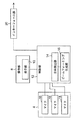
図5は、実施の形態2に係る収音装置2のブロック図である。図5に示すブロック図も、収音装置2における収音に関連するブロックを示すものである。図6(a)は、実施の形態2に係る収音装置2の一方の端部の、利用例を示す図である。図5に示すように、収音装置2は、操作部8a、収音部4、表示部10a、方向駆動部22、インターフェース部20、及び、制御部12を備える。
操作部8aは、図6(a)に示すように、球体(例えば、トラックボール)の形状を有しており、利用者1が球体部分を回すように動かすことにより、球体部分が、前後左右に連続的に回転して、自在に方向付けされるように構成されている。
表示部10aは、操作部8aの直近に備わる。表示部10aは、例えば、LEDによる発光体や、蛍光体による微小なマークなどを付す、矩形の平板、又は、微小な画像を表示する液晶ディスプレイや有機ELディスプレイなどのディスプレイである。
また、表示部10aは、方向駆動部22により向きの変更が駆動される。方向駆動部22は、方向検出部14により検出される操作部8aの方向に合わせて、表示部10aの向きの変更を駆動する。
より詳細には、操作部8aへの操作動作は、例えば、収音装置2内部にて球体(トラックボール)に直交2方向で接する二つの円筒体若しくは円板体の回転に変換される。方向検出部14はこれらの回転量を検出して操作部8の方向を検出する。検出される操作部8aの方向に基づいて、方向駆動部22を構成する(例えば)モータが動作することで、表示部10aの向きの変更が駆動される。方向駆動部22は、別のアクチュエータにより構成されてもよい。
なお、操作部8aは、球体(トラックボール)でなくてもよい。例えば、方向を示し得るレバー、スティック、タッチパッド、若しくはハンドルなどでもよい。
制御部12は、操作部8aの方向を検出する方向検出部14、及び、マイクロフォンアレイにおける指向性を生成するビームフォーミング生成部16を備える。収音部4は、複数のマイク18により構成されるマイクロフォンアレイを含む。インターフェース部20からは、収音部4により収音された音声のデータが外部(例えば、端末機5)に出力される。
[2-2.動作]
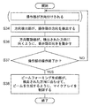
図7は、実施の形態2に係る収音装置2における、操作部8aによる方向付けから、高い指向性を有するビームの生成までの動作を示す、フロー図である。図7を用いて、収音装置2の動作を説明する。
図7は、実施の形態2に係る収音装置2における、操作部8aによる方向付けから、高い指向性を有するビームの生成までの動作を示す、フロー図である。図7を用いて、収音装置2の動作を説明する。
まず、操作部8aが利用者1の操作により方向付けされる。即ち、操作される操作部8aの球体(トラックボール)は、前後左右に連続的に回転して方向付けされる。
制御部12の方向検出部14が、操作部8aの方向を検出する(S34)。
方向駆動部22は、方向検出部14により検出された操作部8aの方向に向くように、表示部10aの向きを動かす(S36)。
図6(b)は、操作部8aの球体(トラックボール)を、収音装置2の一方の端面3の方向から見て左に回転して方向付けしたことにより、(収音装置2の一方の端面3の方向から見て)左を向くように方向駆動部22により動かされた表示部10aの動作例である。図6(b)に示す表示部10aは、矢印Aの方向から眺めるときに所定の表示内容が正しく視認される。また、図6(c)は、操作部8aの球体(トラックボール)を、収音装置2の一方の端面3の方向から見て後ろに回転して方向付けしたことにより、(収音装置2の一方の端面3の方向から見て)後ろ、若しくは、上を向くように方向駆動部22により動かされた表示部10aの動作例である。図6(c)に示す表示部10aは、上方の矢印Bの方向から眺めるときに所定の表示内容が正しく視認される。
S34~S36の動作を経て、表示部10aの向きが、利用者1が眺めたときに所定の表示内容が正しく視認され得る向きで無いならば、操作部8aへの操作は継続され(S37・NO)、S34~S36の動作が繰り返される。
S34~S36の動作を経て、表示部10aの向きが、利用者1が眺めたときに所定の表示内容が正しく視認され得る向きであるならば、操作部8aへの操作は終了し(S37・YES)、このとき方向検出部14により検出される操作部8aの方向が一旦確定する。これを受けて、制御部12のビームフォーミング生成部16が、マイクロフォンアレイを制御して、方向検出部14により検出された方向に合わせて、ビームを生成する(S38)。即ち、ビームフォーミング生成部16は、方向検出部14により検出された方向において、収音の指向性を高めるように、マイクロフォンアレイを制御する。このようにすることにより、収音装置2の表示部10aに対する発声者(利用者)1の方向と、ビームフォーミングにより生成されるビームの方向とが、略一致することになる。
ステップS38に続いて、マイクロフォンアレイを含む収音部4が、発声者(利用者)1の音声を収音する。収音された音声は、制御部12がデータ化してインターフェース部20を介して外部に出力する。
以上のようにして、発声者の音声が、簡単な操作により、指向性を高められたマイクを経由して収音される。
[2-3.効果等]
以上のように、本実施の形態において、収音装置2は、方向を可視的に示し、方向を三次元的且つ連続的に変更可能な操作部8aと、収音に指向性を持つ収音部4と、制御部12と、を備える。制御部12は、操作部8aが示す方向を検出する方向検出部14を有する。制御部12は、方向検出部14が検出する方向に合わせて、収音部4の収音の指向性を制御する。
以上のように、本実施の形態において、収音装置2は、方向を可視的に示し、方向を三次元的且つ連続的に変更可能な操作部8aと、収音に指向性を持つ収音部4と、制御部12と、を備える。制御部12は、操作部8aが示す方向を検出する方向検出部14を有する。制御部12は、方向検出部14が検出する方向に合わせて、収音部4の収音の指向性を制御する。
これにより、収音装置2は、利用者1にとって最適な収音方向が分かりやすいものとなる。利用者1は適切な方向に顔を向けることができる。更に、利用者1は、収音方向を容易に且つ最適に操作できる。
また、本実施の形態において、収音部4は、複数のマイクで構成され、制御部12は、更に、方向検出部14が検出する方向に合わせて、複数のマイクで構成されたマイクロフォンアレイによるビームを制御して、収音の指向性を変更する、ビームフォーミング生成部を有する。
これにより、マイクロフォンアレイを構成する収音部4を備える収音装置2は、利用者1にとって最適な収音方向が分かりやすいものとなる。更に、利用者1は、収音方向を容易に且つ最適に操作できる。
また、本実施の形態において、収音装置2は、更に、方向を可視的に示し、方向検出部14が検出する方向からのみ視認可能な表示部10aを備える。収音装置2は、更に、方向検出部14が検出する方向に合わせて、表示部10aの向きを駆動する方向駆動部22を備える。このことにより、収音装置2の表示部10aに対する利用者1の方向と、マイクロフォンアレイによるビーム(指向性)の方向とが、より一致しやすくなる。
本実施の形態を利用することにより、発声者(利用者)は、周辺の雑音を低減させた状態で、自分の発声を収音することができる。
(他の実施の形態)
以上のように、本出願において開示する技術の例示として、実施の形態1、2を説明した。しかしながら、本開示における技術は、これに限定されず、適宜、変更、置き換え、付加、省略などを行った実施の形態にも適用可能である。また、上記実施の形態1、2で説明した各構成要素を組み合わせて、新たな実施の形態とすることも可能である。
そこで、以下、他の実施の形態をまとめて説明する。
以上のように、本出願において開示する技術の例示として、実施の形態1、2を説明した。しかしながら、本開示における技術は、これに限定されず、適宜、変更、置き換え、付加、省略などを行った実施の形態にも適用可能である。また、上記実施の形態1、2で説明した各構成要素を組み合わせて、新たな実施の形態とすることも可能である。
そこで、以下、他の実施の形態をまとめて説明する。
実施の形態2では、操作部8aによる方向付けに基づいて、表示部10aそのものが向きを変更する。ここで、表示部10aは、操作部8aにより方向付けされた方向から眺めたときのみ、所定の形状が正しく視認される画像を表示する、というものであってもよい。つまり、例えば、操作部8aの球体(トラックボール)が、収音装置2の一方の端面3の方向から見て左に方向付けされると、(収音装置2の一方の端面3の方向から見て)左から眺めるときのみ所定の形状が正しく視認されるような画像を、表示部10aが表示する、というものであってもよい。
図8は、上述の形態に係る収音装置2のブロック図であり、実施の形態2を変更した形態に係るものである。図5のブロック図と比べて、方向駆動部22が省かれており、制御部12における画像生成部16が追加されている。画像生成部24は、操作部8aにより方向付けされた方向から眺めたときのみ、所定の形状が正しく視認される画像を生成する。
図9は、上述の形態に係る収音装置2における、操作部8aによる方向付けから、高い指向性を有するビームの生成までの動作を示す、フロー図である。図7のフロー図と比べると、「方向駆動部22が、方向検出部14により検出された操作部8aの方向に向くように、表示部10aの向きを動かす」のではなく、「画像生成部24が、方向検出部14により検出された操作部8aの方向から眺めたときのみ、所定の形状が正しく視認される画像を生成し、表示部10aに表示する」。このような形態によって、実施の形態2と同様の効果を得られるだけで無く、更に、表示部10aの向きを変更する機構を設ける必要が無いことから、簡素で故障しにくい収音装置2が実現される。
なお、ビームフォーミングは操作部により指示された方向にビームを連続的に可変できるものとして説明したが、ビームフォーミング処理の簡素化のために、複数のアルゴリズムを切り替えることによりビームの方向を変えるように実装しても構わない。
以上のように、本開示における技術の例示として、実施の形態を説明した。そのために、添付図面および詳細な説明を提供した。したがって、添付図面および詳細な説明に記載された構成要素の中には、課題解決のために必須な構成要素だけでなく、上記技術を例示するために、課題解決のためには必須でない構成要素も含まれ得る。そのため、それらの必須ではない構成要素が添付図面や詳細な説明に記載されていることをもって、直ちに、それらの必須ではない構成要素が必須であるとの認定をするべきではない。
また、上述の実施の形態は、本開示における技術を例示するためのものであるから、特許請求の範囲またはその均等の範囲において種々の変更、置き換え、付加、省略などを行うことができる。
本開示は、マイクを介して収音される音声が利用されるシステムに適用可能である。具体的には、音声認識システム、自動翻訳システムなどに、本開示は適用可能である。
1・・・利用者、2・・・収音装置、3・・・端面、4・・・収音部、5・・・端末機、6・・・スピーカ、7・・・球体、8、8a・・・操作部、9・・・円筒、10、10a・・・表示部、11・・・先端部、12・・・制御部、14・・・方向検出部、16・・・ビームフォーミング生成部、18・・・マイク、20・・・インターフェース部、22・・・方向駆動部。
Claims (5)
- 一の方向を可視的に示し、前記方向を三次元的且つ連続的に変更可能な操作部と、
収音に指向性を持つ収音部と、
制御部とを備え、
前記制御部は、前記操作部が示す方向を検出する方向検出部を有し、
前記制御部は、前記方向検出部が検出する方向に合わせて、前記収音部の収音の指向性を制御する、
収音装置。 - 前記収音部は、複数のマイクで構成され、
前記制御部は、更に、
前記方向検出部が検出する方向に合わせて、前記複数のマイクで構成されたマイクロフォンアレイによるビームを制御して、収音の指向性を変更する、ビームフォーミング生成部を有する、
請求項1に記載の収音装置。 - 前記操作部は、前記操作部が示す方向からのみ視認可能な表示部を有する、
請求項1に記載の収音装置。 - 更に、前記方向を可視的に示し、前記方向検出部が検出する方向からのみ視認可能な表示部を備える、
請求項1に記載の収音装置。 - 更に、前記方向検出部が検出する方向に合わせて、前記表示部の向きを駆動する方向駆動部を備える、
請求項4に記載の収音装置。
Priority Applications (2)
| Application Number | Priority Date | Filing Date | Title |
|---|---|---|---|
| JP2017551346A JP6436427B2 (ja) | 2016-03-25 | 2016-09-28 | 収音装置 |
| US15/796,975 US10390133B2 (en) | 2016-03-25 | 2017-10-30 | Sound collection apparatus |
Applications Claiming Priority (2)
| Application Number | Priority Date | Filing Date | Title |
|---|---|---|---|
| JP2016061239 | 2016-03-25 | ||
| JP2016-061239 | 2016-03-25 |
Related Child Applications (1)
| Application Number | Title | Priority Date | Filing Date |
|---|---|---|---|
| US15/796,975 Continuation US10390133B2 (en) | 2016-03-25 | 2017-10-30 | Sound collection apparatus |
Publications (1)
| Publication Number | Publication Date |
|---|---|
| WO2017163286A1 true WO2017163286A1 (ja) | 2017-09-28 |
Family
ID=59900031
Family Applications (1)
| Application Number | Title | Priority Date | Filing Date |
|---|---|---|---|
| PCT/JP2016/004373 WO2017163286A1 (ja) | 2016-03-25 | 2016-09-28 | 収音装置 |
Country Status (3)
| Country | Link |
|---|---|
| US (1) | US10390133B2 (ja) |
| JP (1) | JP6436427B2 (ja) |
| WO (1) | WO2017163286A1 (ja) |
Families Citing this family (1)
| Publication number | Priority date | Publication date | Assignee | Title |
|---|---|---|---|---|
| IT201900019013A1 (it) | 2019-10-16 | 2021-04-16 | Sacmi | Testa di coestrusione multistrato. |
Citations (2)
| Publication number | Priority date | Publication date | Assignee | Title |
|---|---|---|---|---|
| JP2005033811A (ja) * | 2003-07-11 | 2005-02-03 | Fuji Xerox Co Ltd | コミュニケーションシステム、会議を促進するシステム、及びコミュニケーション装置、並びに会議を実行するための方法 |
| JP2011211330A (ja) * | 2010-03-29 | 2011-10-20 | Yamaha Corp | 収音装置および放収音装置 |
Family Cites Families (14)
| Publication number | Priority date | Publication date | Assignee | Title |
|---|---|---|---|---|
| JP4356663B2 (ja) * | 2005-08-17 | 2009-11-04 | ソニー株式会社 | カメラ制御装置および電子会議システム |
| JP5663201B2 (ja) * | 2009-06-04 | 2015-02-04 | 本田技研工業株式会社 | 音源方向推定装置及び音源方向推定方法 |
| CN106231501B (zh) * | 2009-11-30 | 2020-07-14 | 诺基亚技术有限公司 | 用于处理音频信号的方法和装置 |
| JP2011151621A (ja) | 2010-01-21 | 2011-08-04 | Sanyo Electric Co Ltd | 音声制御装置 |
| KR101732135B1 (ko) * | 2010-11-05 | 2017-05-11 | 삼성전자주식회사 | 3차원 영상통신장치 및 3차원 영상통신장치의 영상처리방법 |
| US9746916B2 (en) * | 2012-05-11 | 2017-08-29 | Qualcomm Incorporated | Audio user interaction recognition and application interface |
| JP2014153663A (ja) * | 2013-02-13 | 2014-08-25 | Sony Corp | 音声認識装置、および音声認識方法、並びにプログラム |
| US20140268016A1 (en) * | 2013-03-13 | 2014-09-18 | Kopin Corporation | Eyewear spectacle with audio speaker in the temple |
| KR20170067682A (ko) * | 2014-05-26 | 2017-06-16 | 블라디미르 셔먼 | 음향 신호 수집을 위한 코드 실행가능 방법, 회로, 장치, 시스템 및 관련 컴퓨터 |
| US9898078B2 (en) * | 2015-01-12 | 2018-02-20 | Dell Products, L.P. | Immersive environment correction display and method |
| JP2017028608A (ja) * | 2015-07-27 | 2017-02-02 | 株式会社リコー | ビデオ会議端末機 |
| US20170188140A1 (en) * | 2015-12-24 | 2017-06-29 | Intel Corporation | Controlling audio beam forming with video stream data |
| KR102392113B1 (ko) * | 2016-01-20 | 2022-04-29 | 삼성전자주식회사 | 전자 장치 및 전자 장치의 음성 명령 처리 방법 |
| KR102498364B1 (ko) * | 2016-03-24 | 2023-02-10 | 삼성전자주식회사 | 전자 장치 및 전자 장치에서의 정보 제공 방법 |
-
2016
- 2016-09-28 JP JP2017551346A patent/JP6436427B2/ja active Active
- 2016-09-28 WO PCT/JP2016/004373 patent/WO2017163286A1/ja active Application Filing
-
2017
- 2017-10-30 US US15/796,975 patent/US10390133B2/en active Active
Patent Citations (2)
| Publication number | Priority date | Publication date | Assignee | Title |
|---|---|---|---|---|
| JP2005033811A (ja) * | 2003-07-11 | 2005-02-03 | Fuji Xerox Co Ltd | コミュニケーションシステム、会議を促進するシステム、及びコミュニケーション装置、並びに会議を実行するための方法 |
| JP2011211330A (ja) * | 2010-03-29 | 2011-10-20 | Yamaha Corp | 収音装置および放収音装置 |
Also Published As
| Publication number | Publication date |
|---|---|
| US20180070172A1 (en) | 2018-03-08 |
| US10390133B2 (en) | 2019-08-20 |
| JP6436427B2 (ja) | 2018-12-12 |
| JPWO2017163286A1 (ja) | 2018-03-29 |
Similar Documents
| Publication | Publication Date | Title |
|---|---|---|
| JP6419262B2 (ja) | Asrおよびht入力を有する補助ディスプレイとしてのヘッドセットコンピュータ(hsc) | |
| KR101760013B1 (ko) | 전자 디바이스 및 그 제어방법 | |
| JP6250041B2 (ja) | 骨伝導スピーカーにおける外部振動の削減 | |
| WO2022105784A1 (zh) | 触控笔、电子设备、操作控制方法、装置及终端设备 | |
| JP4972218B1 (ja) | 動作体玩具 | |
| JP2017526024A (ja) | 指向性インタフェースを備えるハンズフリー機器 | |
| WO2017130486A1 (ja) | 情報処理装置、情報処理方法およびプログラム | |
| TW201037593A (en) | Audible list traversal | |
| WO2012138450A1 (en) | Tongue tracking interface apparatus and method for controlling a computer program | |
| US20190227323A1 (en) | Head mounted display device, sound transmission system, and control method for head mounted display device | |
| EP2661105A2 (en) | A system and apparatus for controlling a device with a bone conduction transducer | |
| JP2007253648A (ja) | 入力支援システムおよびそのシステムを構成する車載端末装置 | |
| JP6436427B2 (ja) | 収音装置 | |
| KR20160101572A (ko) | 영상표시 장치 및 그의 소비전력 절감 방법 | |
| JP2019118134A (ja) | 情報処理装置、通信制御方法およびコンピュータプログラム | |
| KR200493961Y1 (ko) | 다기능 무선이어폰 케이스 | |
| CN209746519U (zh) | 一种手机鼠标输入系统 | |
| US20190287489A1 (en) | Head-mounted display apparatus and method for controlling head-mounted display apparatus | |
| US10423383B2 (en) | Intelligent playback system, wearable device and main unit | |
| US11368611B2 (en) | Control method for camera device, camera device, camera system, and storage medium | |
| WO2019054037A1 (ja) | 情報処理装置、情報処理方法、およびプログラム | |
| US11327576B2 (en) | Information processing apparatus, information processing method, and program | |
| KR101988835B1 (ko) | 움직임 가능한 큐브형 마우스 | |
| CN207625614U (zh) | 多键位演示用电容笔及投影手机 | |
| RU110845U1 (ru) | Система управления мобильным устройством посредством поворота головы пользователя |
Legal Events
| Date | Code | Title | Description |
|---|---|---|---|
| ENP | Entry into the national phase |
Ref document number: 2017551346 Country of ref document: JP Kind code of ref document: A |
|
| NENP | Non-entry into the national phase |
Ref country code: DE |
|
| 121 | Ep: the epo has been informed by wipo that ep was designated in this application |
Ref document number: 16895326 Country of ref document: EP Kind code of ref document: A1 |
|
| 122 | Ep: pct application non-entry in european phase |
Ref document number: 16895326 Country of ref document: EP Kind code of ref document: A1 |