WO2017159289A1 - 固体電解質、全固体リチウムイオン二次電池及び固体電解質の製造方法 - Google Patents
固体電解質、全固体リチウムイオン二次電池及び固体電解質の製造方法 Download PDFInfo
- Publication number
- WO2017159289A1 WO2017159289A1 PCT/JP2017/007064 JP2017007064W WO2017159289A1 WO 2017159289 A1 WO2017159289 A1 WO 2017159289A1 JP 2017007064 W JP2017007064 W JP 2017007064W WO 2017159289 A1 WO2017159289 A1 WO 2017159289A1
- Authority
- WO
- WIPO (PCT)
- Prior art keywords
- ratio
- solid electrolyte
- layer
- lithium
- atom
- Prior art date
- Legal status (The legal status is an assumption and is not a legal conclusion. Google has not performed a legal analysis and makes no representation as to the accuracy of the status listed.)
- Ceased
Links
Images



Classifications
-
- H—ELECTRICITY
- H01—ELECTRIC ELEMENTS
- H01M—PROCESSES OR MEANS, e.g. BATTERIES, FOR THE DIRECT CONVERSION OF CHEMICAL ENERGY INTO ELECTRICAL ENERGY
- H01M10/00—Secondary cells; Manufacture thereof
- H01M10/05—Accumulators with non-aqueous electrolyte
- H01M10/056—Accumulators with non-aqueous electrolyte characterised by the materials used as electrolytes, e.g. mixed inorganic/organic electrolytes
- H01M10/0561—Accumulators with non-aqueous electrolyte characterised by the materials used as electrolytes, e.g. mixed inorganic/organic electrolytes the electrolyte being constituted of inorganic materials only
- H01M10/0562—Solid materials
-
- C—CHEMISTRY; METALLURGY
- C01—INORGANIC CHEMISTRY
- C01B—NON-METALLIC ELEMENTS; COMPOUNDS THEREOF; METALLOIDS OR COMPOUNDS THEREOF NOT COVERED BY SUBCLASS C01C
- C01B21/00—Nitrogen; Compounds thereof
- C01B21/082—Compounds containing nitrogen and non-metals and optionally metals
- C01B21/097—Compounds containing nitrogen and non-metals and optionally metals containing phosphorus atoms
-
- C—CHEMISTRY; METALLURGY
- C23—COATING METALLIC MATERIAL; COATING MATERIAL WITH METALLIC MATERIAL; CHEMICAL SURFACE TREATMENT; DIFFUSION TREATMENT OF METALLIC MATERIAL; COATING BY VACUUM EVAPORATION, BY SPUTTERING, BY ION IMPLANTATION OR BY CHEMICAL VAPOUR DEPOSITION, IN GENERAL; INHIBITING CORROSION OF METALLIC MATERIAL OR INCRUSTATION IN GENERAL
- C23C—COATING METALLIC MATERIAL; COATING MATERIAL WITH METALLIC MATERIAL; SURFACE TREATMENT OF METALLIC MATERIAL BY DIFFUSION INTO THE SURFACE, BY CHEMICAL CONVERSION OR SUBSTITUTION; COATING BY VACUUM EVAPORATION, BY SPUTTERING, BY ION IMPLANTATION OR BY CHEMICAL VAPOUR DEPOSITION, IN GENERAL
- C23C14/00—Coating by vacuum evaporation, by sputtering or by ion implantation of the coating forming material
- C23C14/06—Coating by vacuum evaporation, by sputtering or by ion implantation of the coating forming material characterised by the coating material
- C23C14/0676—Oxynitrides
-
- C—CHEMISTRY; METALLURGY
- C23—COATING METALLIC MATERIAL; COATING MATERIAL WITH METALLIC MATERIAL; CHEMICAL SURFACE TREATMENT; DIFFUSION TREATMENT OF METALLIC MATERIAL; COATING BY VACUUM EVAPORATION, BY SPUTTERING, BY ION IMPLANTATION OR BY CHEMICAL VAPOUR DEPOSITION, IN GENERAL; INHIBITING CORROSION OF METALLIC MATERIAL OR INCRUSTATION IN GENERAL
- C23C—COATING METALLIC MATERIAL; COATING MATERIAL WITH METALLIC MATERIAL; SURFACE TREATMENT OF METALLIC MATERIAL BY DIFFUSION INTO THE SURFACE, BY CHEMICAL CONVERSION OR SUBSTITUTION; COATING BY VACUUM EVAPORATION, BY SPUTTERING, BY ION IMPLANTATION OR BY CHEMICAL VAPOUR DEPOSITION, IN GENERAL
- C23C14/00—Coating by vacuum evaporation, by sputtering or by ion implantation of the coating forming material
- C23C14/22—Coating by vacuum evaporation, by sputtering or by ion implantation of the coating forming material characterised by the process of coating
- C23C14/34—Sputtering
-
- C—CHEMISTRY; METALLURGY
- C23—COATING METALLIC MATERIAL; COATING MATERIAL WITH METALLIC MATERIAL; CHEMICAL SURFACE TREATMENT; DIFFUSION TREATMENT OF METALLIC MATERIAL; COATING BY VACUUM EVAPORATION, BY SPUTTERING, BY ION IMPLANTATION OR BY CHEMICAL VAPOUR DEPOSITION, IN GENERAL; INHIBITING CORROSION OF METALLIC MATERIAL OR INCRUSTATION IN GENERAL
- C23C—COATING METALLIC MATERIAL; COATING MATERIAL WITH METALLIC MATERIAL; SURFACE TREATMENT OF METALLIC MATERIAL BY DIFFUSION INTO THE SURFACE, BY CHEMICAL CONVERSION OR SUBSTITUTION; COATING BY VACUUM EVAPORATION, BY SPUTTERING, BY ION IMPLANTATION OR BY CHEMICAL VAPOUR DEPOSITION, IN GENERAL
- C23C14/00—Coating by vacuum evaporation, by sputtering or by ion implantation of the coating forming material
- C23C14/22—Coating by vacuum evaporation, by sputtering or by ion implantation of the coating forming material characterised by the process of coating
- C23C14/34—Sputtering
- C23C14/35—Sputtering by application of a magnetic field, e.g. magnetron sputtering
- C23C14/352—Sputtering by application of a magnetic field, e.g. magnetron sputtering using more than one target
-
- H—ELECTRICITY
- H01—ELECTRIC ELEMENTS
- H01B—CABLES; CONDUCTORS; INSULATORS; SELECTION OF MATERIALS FOR THEIR CONDUCTIVE, INSULATING OR DIELECTRIC PROPERTIES
- H01B1/00—Conductors or conductive bodies characterised by the conductive materials; Selection of materials as conductors
- H01B1/06—Conductors or conductive bodies characterised by the conductive materials; Selection of materials as conductors mainly consisting of other non-metallic substances
- H01B1/08—Conductors or conductive bodies characterised by the conductive materials; Selection of materials as conductors mainly consisting of other non-metallic substances oxides
-
- H—ELECTRICITY
- H01—ELECTRIC ELEMENTS
- H01M—PROCESSES OR MEANS, e.g. BATTERIES, FOR THE DIRECT CONVERSION OF CHEMICAL ENERGY INTO ELECTRICAL ENERGY
- H01M10/00—Secondary cells; Manufacture thereof
- H01M10/05—Accumulators with non-aqueous electrolyte
- H01M10/052—Li-accumulators
- H01M10/0525—Rocking-chair batteries, i.e. batteries with lithium insertion or intercalation in both electrodes; Lithium-ion batteries
-
- H—ELECTRICITY
- H01—ELECTRIC ELEMENTS
- H01M—PROCESSES OR MEANS, e.g. BATTERIES, FOR THE DIRECT CONVERSION OF CHEMICAL ENERGY INTO ELECTRICAL ENERGY
- H01M10/00—Secondary cells; Manufacture thereof
- H01M10/05—Accumulators with non-aqueous electrolyte
- H01M10/058—Construction or manufacture
- H01M10/0585—Construction or manufacture of accumulators having only flat construction elements, i.e. flat positive electrodes, flat negative electrodes and flat separators
-
- H—ELECTRICITY
- H01—ELECTRIC ELEMENTS
- H01M—PROCESSES OR MEANS, e.g. BATTERIES, FOR THE DIRECT CONVERSION OF CHEMICAL ENERGY INTO ELECTRICAL ENERGY
- H01M4/00—Electrodes
- H01M4/02—Electrodes composed of, or comprising, active material
- H01M4/36—Selection of substances as active materials, active masses, active liquids
- H01M4/38—Selection of substances as active materials, active masses, active liquids of elements or alloys
- H01M4/381—Alkaline or alkaline earth metals elements
- H01M4/382—Lithium
-
- H—ELECTRICITY
- H01—ELECTRIC ELEMENTS
- H01M—PROCESSES OR MEANS, e.g. BATTERIES, FOR THE DIRECT CONVERSION OF CHEMICAL ENERGY INTO ELECTRICAL ENERGY
- H01M4/00—Electrodes
- H01M4/02—Electrodes composed of, or comprising, active material
- H01M4/36—Selection of substances as active materials, active masses, active liquids
- H01M4/48—Selection of substances as active materials, active masses, active liquids of inorganic oxides or hydroxides
- H01M4/52—Selection of substances as active materials, active masses, active liquids of inorganic oxides or hydroxides of nickel, cobalt or iron
- H01M4/525—Selection of substances as active materials, active masses, active liquids of inorganic oxides or hydroxides of nickel, cobalt or iron of mixed oxides or hydroxides containing iron, cobalt or nickel for inserting or intercalating light metals, e.g. LiNiO2, LiCoO2 or LiCoOxFy
-
- C—CHEMISTRY; METALLURGY
- C01—INORGANIC CHEMISTRY
- C01P—INDEXING SCHEME RELATING TO STRUCTURAL AND PHYSICAL ASPECTS OF SOLID INORGANIC COMPOUNDS
- C01P2002/00—Crystal-structural characteristics
- C01P2002/80—Crystal-structural characteristics defined by measured data other than those specified in group C01P2002/70
- C01P2002/82—Crystal-structural characteristics defined by measured data other than those specified in group C01P2002/70 by IR- or Raman-data
-
- C—CHEMISTRY; METALLURGY
- C01—INORGANIC CHEMISTRY
- C01P—INDEXING SCHEME RELATING TO STRUCTURAL AND PHYSICAL ASPECTS OF SOLID INORGANIC COMPOUNDS
- C01P2006/00—Physical properties of inorganic compounds
- C01P2006/40—Electric properties
-
- H—ELECTRICITY
- H01—ELECTRIC ELEMENTS
- H01M—PROCESSES OR MEANS, e.g. BATTERIES, FOR THE DIRECT CONVERSION OF CHEMICAL ENERGY INTO ELECTRICAL ENERGY
- H01M2300/00—Electrolytes
- H01M2300/0017—Non-aqueous electrolytes
- H01M2300/0065—Solid electrolytes
- H01M2300/0068—Solid electrolytes inorganic
- H01M2300/0071—Oxides
-
- Y—GENERAL TAGGING OF NEW TECHNOLOGICAL DEVELOPMENTS; GENERAL TAGGING OF CROSS-SECTIONAL TECHNOLOGIES SPANNING OVER SEVERAL SECTIONS OF THE IPC; TECHNICAL SUBJECTS COVERED BY FORMER USPC CROSS-REFERENCE ART COLLECTIONS [XRACs] AND DIGESTS
- Y02—TECHNOLOGIES OR APPLICATIONS FOR MITIGATION OR ADAPTATION AGAINST CLIMATE CHANGE
- Y02E—REDUCTION OF GREENHOUSE GAS [GHG] EMISSIONS, RELATED TO ENERGY GENERATION, TRANSMISSION OR DISTRIBUTION
- Y02E60/00—Enabling technologies; Technologies with a potential or indirect contribution to GHG emissions mitigation
- Y02E60/10—Energy storage using batteries
-
- Y—GENERAL TAGGING OF NEW TECHNOLOGICAL DEVELOPMENTS; GENERAL TAGGING OF CROSS-SECTIONAL TECHNOLOGIES SPANNING OVER SEVERAL SECTIONS OF THE IPC; TECHNICAL SUBJECTS COVERED BY FORMER USPC CROSS-REFERENCE ART COLLECTIONS [XRACs] AND DIGESTS
- Y02—TECHNOLOGIES OR APPLICATIONS FOR MITIGATION OR ADAPTATION AGAINST CLIMATE CHANGE
- Y02P—CLIMATE CHANGE MITIGATION TECHNOLOGIES IN THE PRODUCTION OR PROCESSING OF GOODS
- Y02P70/00—Climate change mitigation technologies in the production process for final industrial or consumer products
- Y02P70/50—Manufacturing or production processes characterised by the final manufactured product
Definitions
- the present invention relates to a solid electrolyte, an all-solid lithium ion secondary battery, and a method for producing a solid electrolyte.
- Non-Patent Document 2 describes that lithium ion conductivity is improved as the N / P ratio (atomic ratio in the layer) of LiPON formed in a layer shape is increased.
- the lithium ion conductivity of LiPON is not only the above-mentioned N / P ratio but also N 2 (nitrogen molecule) without binding to P atoms among all N atoms.
- N 2 nitrogen molecule
- Non-Patent Document 3 N 2 is detected in the Raman spectrum of LiPON, which is N 2 in the measurement atmosphere was believed to have been detected.
- the present invention has been made in view of the above-described circumstances, and an object thereof is to provide a solid electrolyte capable of improving lithium ion conductivity, an all-solid lithium ion secondary battery, and a method for producing the solid electrolyte.
- the solid electrolyte according to the present invention is composed of lithium nitride lithium phosphate (LiPON).
- LiPON lithium nitride lithium phosphate
- the ratio of the peak intensity of N atom in a single bond with one P atom and double bond with one P atom to the peak intensity in N 2 state in the Raman spectrum of lithium nitride phosphate, The product of the ratio of the content of P to the content of P atoms is 0.40 or more.
- a solid electrolyte capable of improving lithium ion conductivity, an all-solid lithium ion secondary battery, and a method for producing a solid electrolyte.
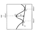
- Sectional drawing which shows the structure of an all-solid-state lithium ion secondary battery typically Schematic diagram for explaining the calculation method of the PNP / N 2 ratio Schematic diagram for explaining the calculation method of the PNP / N 2 ratio Schematic diagram for explaining the calculation method of the POP / PO ratio
- FIG. 1 is a cross-sectional view schematically showing the configuration of an all solid lithium ion secondary battery 100.
- the all solid lithium ion secondary battery 100 configured in a plate shape is a secondary battery (rechargeable battery) that can be repeatedly used by charging and discharging.
- the all solid lithium ion secondary battery 100 includes a positive electrode side current collecting layer 101, a negative electrode side current collecting layer 102, exterior materials 103 and 104, a current collecting connection layer 105, a positive electrode plate 106, a solid electrolyte layer 107, and a negative electrode layer 108. .
- the positive electrode side current collecting layer 101, the current collecting connection layer 105, the positive electrode plate 106, the solid electrolyte layer 107, the negative electrode layer 108, and the negative electrode side current collecting layer 102 are sequentially stacked. It is constituted by being done.
- the end in the plate surface direction of the all-solid-state lithium ion secondary battery 100 is sealed with exterior materials 103 and 104.
- the positive electrode 110 is constituted by the positive electrode side current collecting layer 101, the current collecting connection layer 105 and the positive electrode plate 106.
- a negative electrode 120 is constituted by the negative electrode side current collecting layer 102 and the negative electrode layer 108.
- Positive electrode side current collecting layer 101 The positive current collecting layer 101 is disposed outside the positive electrode plate 106. The positive current collecting layer 101 is mechanically and electrically connected to the positive electrode plate 106 through the current collecting connection layer 105. The positive electrode side current collecting layer 101 functions as a positive electrode current collector.
- the positive electrode side current collecting layer 101 can be made of metal.
- the metal constituting the positive electrode side current collecting layer 101 include stainless steel, aluminum, copper, platinum, nickel and the like, and stainless steel is particularly preferable.
- the positive electrode side current collecting layer 101 can be formed in a plate shape or a foil shape, and a foil shape is particularly preferable. Therefore, it is particularly preferable to use a stainless steel foil as the positive electrode side current collecting layer 101.
- Negative electrode side current collecting layer 102 The negative electrode side current collecting layer 102 is disposed outside the negative electrode layer 108. The negative electrode side current collecting layer 102 is mechanically and electrically connected to the negative electrode layer 108. The negative electrode side current collecting layer 102 functions as a negative electrode current collector.
- the negative electrode side current collecting layer 102 can be made of metal.
- the negative electrode side current collecting layer 102 can be made of the same material as that of the positive electrode side current collecting layer 101.
- Exterior material 103, 104 The exterior materials 103 and 104 seal a gap between the positive electrode side current collecting layer 101 and the negative electrode side current collecting layer 102.
- the exterior materials 103 and 104 surround the side of the unit cell constituted by the positive electrode plate 106, the solid electrolyte layer 107, and the negative electrode layer 108.
- the exterior materials 103 and 104 suppress intrusion of moisture and the like into the interior.
- the exterior materials 103 and 104 can be made of an electrically insulating sealing material.
- As the sealing material a resin-based sealing material containing a resin can be used.
- the exterior materials 103 and 104 can be formed by laminating resin films, dispensing liquid resin, or the like.
- the current collecting connection layer 105 is disposed between the positive electrode plate 106 and the positive electrode side current collecting layer 101.
- the current collecting connection layer 105 mechanically and electrically joins the positive electrode plate 106 to the positive electrode side current collecting layer 101.
- the current collecting connection layer 105 includes a conductive material and an adhesive.
- a conductive material conductive carbon or the like can be used.
- an epoxy-based resin material can be used.
- Positive electrode plate 106 The positive electrode plate 106 is an example of a “positive electrode material” according to the present embodiment.
- the positive electrode plate 106 is formed into a plate shape.
- the thickness of the positive electrode plate 106 is not particularly limited, but is preferably 20 ⁇ m or more, more preferably 25 ⁇ m or more, and further preferably 30 ⁇ m or more.
- the positive electrode plate 106 can be made of a known positive electrode active material.
- a lithium composite oxide is suitable.
- the lithium composite oxide is Li x MO 2 (0.05 ⁇ x ⁇ 1.10, M is at least one transition metal, and M is typically one of Co, Ni, and Mn. Including the above.)
- the lithium composite oxide has a layered rock salt structure.
- lithium composite oxide examples include Li x CoO 2 (lithium cobaltate), Li x NiO 2 (lithium nickelate), Li x MnO 2 (lithium manganate), and Li x NiMnO 2 (nickel / lithium manganate).
- Li x NiCoO 2 (nickel / lithium cobaltate) Li x CoNiMnO 2 (cobalt / nickel / lithium manganate)
- Li x CoMnO 2 (cobalt / lithium manganate) and the like
- Li x CoO 2 is particularly preferable.
- Negative electrode layer 108 The negative electrode layer 108 is an example of a “negative electrode material” according to the present embodiment.
- the negative electrode layer 108 is disposed on the solid electrolyte layer 107.
- the negative electrode layer 108 contains lithium metal as a main component.
- the negative electrode layer 108 may be a lithium-containing metal film formed on the solid electrolyte layer 107.
- the lithium-containing metal film can be formed by a vacuum deposition method, a sputtering method, a CVD method, or the like.
- the thickness of the negative electrode layer 108 is not particularly limited, but can be 200 ⁇ m or less.
- Solid electrolyte layer 107 The solid electrolyte layer 107 is an example of a “solid electrolyte” according to the present embodiment.
- the solid electrolyte layer 107 is disposed between the positive electrode plate 106 and the negative electrode layer 108.
- the thickness of the solid electrolyte layer 107 is not particularly limited, but is preferably 0.1 to 10 ⁇ m, more preferably 0.2 to 8.0 ⁇ m, and particularly preferably 0.3 to 7.0 ⁇ m. By setting the thickness of the solid electrolyte layer 107 to 0.1 ⁇ m or more, it is possible to further suppress a film defect when an all-solid battery is formed or a short circuit between electrodes due to insufficient withstand voltage of the solid electrolyte layer 107 itself. Moreover, the resistance of the solid electrolyte layer 107 can be kept low by setting the thickness of the solid electrolyte layer 107 to 10 ⁇ m or less.
- the solid electrolyte layer 107 is made of lithium nitride nitride (hereinafter referred to as “LiPON”), which is one of oxide ceramic materials.
- LiPON lithium nitride nitride
- the composition formula of LiPON is, for example, Li 2.9 PO 3.3 N 0.46 .
- the solid electrolyte layer 107 preferably has high lithium ion conductivity.
- the lithium ion conductivity of the solid electrolyte layer 107 is preferably larger than 2.0 [ ⁇ S / cm], more preferably 3.0 [ ⁇ S / cm] or more, and particularly preferably 3.6 [ ⁇ S / cm] or more. .
- Components of the solid electrolyte layer 107) 1. Overview Conventionally, the lithium ion conductivity of LiPON constituting the solid electrolyte layer 107 increases as the ratio of the atomic composition percentage of N atoms to the atomic composition percentage of P atoms (hereinafter referred to as “N / P ratio”) increases. It is known (see Non-Patent Document 2). The atomic composition percentage is synonymous with the content of each atom, and the N / P ratio is an index indicating the content of N atoms in LiPON.
- N atom existing as the N 2 state are unknown, but among all the N atoms included in LiPON, the N atom is present in a state where N atoms are bonded together without being bonded to P atoms. is there.
- the N atom bonded to the P atom is an N atom bonded to the P atom that does not exist alone as the N 2 state among all the N atoms included in LiPON.
- PNP PNP
- the other is a form in which one N atom is single-bonded to each of three P atoms.
- PNP is dominant, and PNP can detect the peak intensity in the Raman spectrum more easily. Pay particular attention to the direction.
- PNP / N 2 ratio multiplied by N / P ratio The ratio of the peak intensity of the PNP state to the peak intensity of the N 2 state in the Raman spectrum of the solid electrolyte layer 107 (hereinafter referred to as “PNP / N 2 ratio”).
- the multiplication value with the N / P ratio in the solid electrolyte layer 107 is 0.40 or more. By setting the multiplication value to 0.40 or more, N atoms bonded to P atoms are abundant, so that lithium ion conductivity of LiPON can be improved. In addition, by setting the multiplication value to 0.40 or more, N atoms present alone as the N 2 state are reduced.
- the multiplication value is preferably 0.70 or more.
- the PNP / N 2 ratio increases as the number of N atoms present as the N 2 state decreases, and increases as the number of N atoms bonded to the P atom increases.
- the N / P ratio increases as the N atom content increases, and increases as the P atom content decreases. Therefore, the product of the PNP / N 2 ratio and the N / P ratio varies depending on the combination of these conditions.
- the multiplication value can be adjusted by the chamber internal pressure at the time of film formation of LiPON by the facing target type RF sputtering method.
- the PNP / N 2 ratio can be set to 1.30 or more, for example.
- the PNP / N 2 ratio is preferably 1.50 or more, more preferably 2.00 or more, and particularly preferably 2.67 or more.
- the N / P ratio can be set to 0.10 or more, for example.
- the N / P ratio is preferably 0.15 or more, more preferably 0.22 or more, and particularly preferably 0.26 or more.
- POP / PO ratio In LiPON constituting the solid electrolyte layer 107, P atoms and O atoms are bonded. There are two bonding forms of P atom and O atom. One is a form in which one O atom is single-bonded to each of two P atoms. The other is a form in which one O atom is single-bonded to one P atom. In the following description, the former combination form is expressed as “POP”, and the latter combination form is expressed as “PO”. POP is a state in which an O atom is single-bonded with two P atoms, and cross-linking of P in LiPON is further promoted.
- the ratio of the peak intensity of the POP to the peak intensity of the PO in the Raman spectrum of the solid electrolyte layer 107 (hereinafter referred to as “POP / PO ratio”) can be, for example, 1.00 or more.
- the POP / PO ratio is preferably 1.20 or more, more preferably 1.45 or more, and particularly preferably 2.85 or more.
- Li / P ratio The ratio of the atomic composition percentage of Li atoms to the atomic composition percentage of P atoms in LiPON constituting the solid electrolyte layer 107 (hereinafter referred to as “Li / P ratio”) is, for example, 3.1 or less. Can do.
- the Li / P ratio is preferably 2.8 or less, more preferably 2.6 or less, and particularly preferably 2.4 or less. By reducing the Li / P ratio, the lithium ion conductivity of LiPON can be further improved.
- the form of the N 2 state in the Raman measurement is detected in the vicinity of 2330 cm ⁇ 1 . Therefore, as shown in FIG. 2B, connecting the scattering intensity value B2 of the scattered intensity values A2 and Raman shift 2380Cm -1 of Raman shift 2280 cm -1 in a linear line L2. Then, define the height H2 of the scattering intensity value C2 of the Raman shift 2330Cm -1 relative to the linear line L2 connecting the scattering intensity values A2, B2 as the peak intensity of N 2.
- the PNP / N 2 ratio is calculated by dividing the height ratio H1 by the height H2.
- XPS measurement X-ray photoelectron spectroscopy measurement
- RSF relative sensitivity coefficient
- XPS measurement is performed on the inside of an Ar sputtered film (hereinafter abbreviated) from the outermost surface of the LiPON layer, and Li, P, O, N, which are elements forming the LiPON layer, and C detected as impurities are detected.
- the N / P ratio is calculated by quantifying all of these to make a total of 100%, quantifying the atomic composition percentage of N atoms and the atomic composition percentage of P atoms.
- the POP / PO ratio is calculated by dividing the height ratio H3 by the height H4.
- a substrate (positive plate 106 when producing an all-solid-state lithium secondary battery) is placed in the chamber of the opposed target type RF sputtering apparatus. Then, a solid electrolyte layer 107 made of LiPON is formed on the substrate by an opposed target type RF sputtering method.
- the opposed target type RF sputtering method is a method in which two targets are placed facing each other, a plasma is constrained between the targets by a magnetic field between the opposed targets, and the film is placed on a deposition substrate placed perpendicular to the target surface. This is a method of forming a film.
- the plasma is confined between the targets as compared with the conventionally used magnetron type RF sputtering method, and in the plasma, ⁇ electrons, recoil sputtering gas, sputtered particles, etc. collide with each other.
- N 2 nitrogen molecule
- the substrate is not exposed to the plasma as compared with the magnetron type RF sputtering method, it is possible to prevent high-energy negative ions and electrons from being incident on the substrate. Therefore, since the rise in substrate temperature can be suppressed, residual stress after film formation can be suppressed. As a result, the charge / discharge cycle characteristics may be improved by using this LiPON layer in an all-solid battery.
- the multiplication value of the above-described PNP / N 2 ratio and N / P ratio can be set to 0.40 or more. Further, the multiplication value can be arbitrarily adjusted by adjusting the chamber internal pressure within the range of 1 Pa or less.
- a lithium phosphate sintered body is used for the target, nitrogen (N 2 ) is used for the sputtering gas, the amount of gas introduced is 5 to 50 sccm, and the output per target area is 0.5 to 3.5 W. / Cm 2 .
- the thickness of the solid electrolyte layer 107 can be appropriately adjusted according to the sputtering time.
- Solid electrolyte (LiPON layer) according to the present invention will be described below, but the present invention is not limited to the examples described below.
- Example 1 First, a SUS substrate on which a 500-mm gold film was formed by DC sputtering was prepared.
- the SUS substrate on which the gold film was formed was placed in the chamber of the opposed target type RF sputtering apparatus. Then, a LiPON layer having a thickness of about 1 to 5 ⁇ m was formed on the surface of the gold film by an opposed target type RF sputtering method.
- a lithium phosphate sintered body (density 2.38 g / cm 3 ) is used for the target, N 2 is used for the sputtering gas, the gas introduction amount is 10 sccm, and the output per target area is 2.5 W / cm. 2 and the chamber internal pressure was 0.2 Pa.
- a mask having a 5 mm ⁇ 5 mm window was placed on the surface of the LiPON layer, and a 500-mm gold film was formed by DC sputtering.
- LiPON layer with lithium metal was incorporated into a stainless steel CR2032 case to form a coin cell.
- Comparative Example 1 A coin cell of Comparative Example 1 was produced in the same process as Example 1 except that the LiPON layer was formed by magnetron RF sputtering.
- the same lithium phosphate sintered body (density 2.38 g / cm 3 ) as in Example 1 was used as the magnetron RF sputtering target, N 2 was used as the sputtering gas, the gas introduction amount was 20 sccm, and the target The output per area was 2.5 W / cm 2 and the chamber internal pressure was 0.2 Pa.
- Examples 2 to 5 Coins cells of Examples 2 to 5 and Comparative Example 2 were manufactured in the same process as Example 1 except that the chamber internal pressure when forming the LiPON layer was changed as shown in Table 1.
- X-ray photoelectron spectroscopy measurement (Calculation of N / P ratio) was performed, and the composition was quantified by the relative sensitivity coefficient (RSF) method from the bonding state of atoms in the LiPON layer.
- RSF relative sensitivity coefficient
- For XPS measurement using an XPS measuring device (ESCA-5700ci manufactured by ULVAC-PHI), monolithic AlK ⁇ rays as an X-ray source are used as a reference for charging correction with respect to the Ar sputtered film from the outermost surface of the LiPON layer. C1s (284.8 eV) was used.
- the Raman spectrum of the LiPON layer was acquired using microscopic Raman spectroscopy.
- LabRAM ARAMIS manufactured by HORIBA, Ltd. was used, and a visible light laser (green, wavelength 532 nm, output 24 W) was irradiated perpendicularly to the LiPON layer, and backscattered Raman scattered light was detected.
- the measurement range of the Raman measurement was 70cm -1 ⁇ 2500cm -1.
- the scattering intensity value C1 of the Raman shift 755 cm -1 relative to the primary line L1 connecting the scattering intensity value B1 of the scattering intensity value A1 and the Raman shift 850 cm -1 Raman shift 700 cm -1 Height H1 was defined as the peak intensity of PNP (see FIG. 2A).
- the scattering intensity value C2 of the Raman shift 2330Cm -1 relative to the linear line L2 connecting the scattering intensity value B2 of the scattered intensity values A2 and Raman shift 2380Cm -1 of Raman shift 2280 cm -1 Height H2 was defined as the peak intensity of N 2 (see FIG. 2B).
- the scattering intensity value C4 of the Raman shift 950 cm -1 relative to the linear line L4 connecting the scattering intensity value B3 of the scattered intensity value A3 and the Raman shift 980 cm -1 Raman shift 850 cm -1 Height H4 was defined as the peak intensity of PO (see FIG. 3).
- the POP / PO ratio (peak intensity ratio) was calculated by dividing the height ratio H3 by the height H4. The calculation results are shown in Table 1.
- Li / P ratio (atomic ratio) was measured by inductively coupled plasma emission analysis of a solution in which each LiPON layer was dissolved in an acid. The measurement results are shown in Table 1.
- the film stress was calculated using ⁇ ) L2 ⁇ * h2 / t.
- E is the Young's modulus (64 GPa) of the glass
- ⁇ is the Poisson's ratio (0.208) of the glass
- t is the thickness of the LiPON layer.
- Table 1 The calculation results are shown in Table 1.
- Example 1 As shown in Table 1, in Examples 1 to 5 in which the multiplication value of the PNP / N 2 ratio (peak intensity ratio) and the N / P ratio (atomic ratio) is 0.40 or more, compared with Comparative Examples 1 and 2.
- the lithium ion conductivity could be improved.
- Example 1 and Comparative Example 1 have the same N / P ratio, Example 1 has a larger PNP / N 2 ratio than Comparative Example 1, so that N atoms present alone are reduced. , There is a possibility that it can be suppressed that the insulating property and durability of the LiPON layer are lowered due to the vacancy in the space where N atoms exist in the N 2 state.
- the chamber internal pressure at the time of forming the LiPON layer by the facing target type RF sputtering method may be set to 1 Pa or less, and the N / P ratio increases as the chamber internal pressure decreases. Therefore, it was confirmed that the multiplication value was increased.
- Example 1 using the facing target type RF sputtering method the residual stress could be greatly reduced as compared with Comparative Example 1 using the magnetron type RF sputtering method. From the above, if an all-solid-state battery is produced with the LiPON layer of the present invention, the residual stress between the positive electrode material and the LiPON layer can be reduced, so that the charge / discharge cycle characteristics may be improved.
- Example 1 in Examples 1 to 5, it was confirmed that the lithium ion conductivity was improved as the N / P ratio was increased.
- the N / P ratio is 0.26 or more
- the amount of N atoms introduced can be increased compared to Examples 2 and 5, and thus lithium ion conductivity can be significantly improved. did it.
- the PNP / N 2 ratio is large even at substantially the same N / P ratio, and as a result, the larger the multiplier value, the higher the lithium ion conductivity. It can be seen that the lithium ion conductivity is controlled by the product of the PNP / N 2 ratio and the N / P ratio rather than just the N / P ratio.
Landscapes
- Chemical & Material Sciences (AREA)
- Chemical Kinetics & Catalysis (AREA)
- Engineering & Computer Science (AREA)
- General Chemical & Material Sciences (AREA)
- Electrochemistry (AREA)
- Materials Engineering (AREA)
- Organic Chemistry (AREA)
- Inorganic Chemistry (AREA)
- Manufacturing & Machinery (AREA)
- Mechanical Engineering (AREA)
- Metallurgy (AREA)
- Physics & Mathematics (AREA)
- Condensed Matter Physics & Semiconductors (AREA)
- General Physics & Mathematics (AREA)
- Secondary Cells (AREA)
- Battery Electrode And Active Subsutance (AREA)
- Conductive Materials (AREA)
Abstract
固体電解質は、窒化リン酸リチウム(LiPON)によって構成される。窒化リン酸リチウムのラマン分光スペクトルにおける、1つのP原子と単結合し、かつ、1つのP原子と二重結合した状態のN原子のピーク強度のN2状態のピーク強度に対する比と、N原子の含有量のP原子の含有量に対する比との乗算値が0.40以上である。
Description
本発明は、固体電解質、全固体リチウムイオン二次電池及び固体電解質の製造方法に関する。
近年、正極層と固体電解質層と負極層とを備える全固体リチウムイオン二次電池の開発が進められている。固体電解質層を構成する材料としは、高いリチウムイオン伝導性を有する窒化リン酸リチウム系セラミックス材料(以下、「LiPON」という。)が好適である(例えば、非特許文献1~非特許文献3参照)。特に、非特許文献2では、層状に形成したLiPONにおけるN/P比(層中の原子比)を大きくするほどリチウムイオン伝導性が向上するとされている。
J.B.Bates等著、「Electrical properties of amorphous lithium electrolyte thin films」、Solid State Ionics 53-56(1992)647-654
B.Fleutot等著、「Investigation of the local structure of LiPON thin films to better understand the role of nitrogen on their performance」、Solid State Ionics 186(2011)29-36
Tristan Pichonat等著、「Further studies on the lithium phosphorus oxynitride solid electrolyte」、Materials Chemistry and Physics 123 (2010) 231-235
ところで、全固体リチウムイオン二次電池のさらなる高性能化を図るため、LiPONのリチウムイオン伝導性をより向上させたいという要請がある。そこで、本発明者等が鋭意検討した結果、LiPONのリチウムイオン伝導性は、前述のN/P比だけでなく、全てのN原子のうちP原子と結合することなくN2(窒素分子)として単独で存在するN原子の割合の影響を受けているという新たな知見を得た。
なお、非特許文献3では、LiPONのラマン分光スペクトルにおいてN2が検出されているが、これは測定雰囲気中のN2が検出されているものと思われていた。
本発明は、上述の状況に鑑みてなされたものであり、リチウムイオン伝導性を向上可能な固体電解質、全固体リチウムイオン二次電池及び固体電解質の製造方法を提供することを目的とする。
本発明に係る固体電解質は、窒化リン酸リチウム(LiPON)によって構成される。窒化リン酸リチウムのラマン分光スペクトルにおける、1つのP原子と単結合し、かつ、1つのP原子と二重結合した状態のN原子のピーク強度のN2状態のピーク強度に対する比と、N原子の含有量のP原子の含有量に対する比との乗算値が0.40以上である。
本発明によれば、リチウムイオン伝導性を向上可能な固体電解質、全固体リチウムイオン二次電池及び固体電解質の製造方法を提供することができる。
(全固体リチウムイオン二次電池100)
図1は、全固体リチウムイオン二次電池100の構成を模式的に示す断面図である。板片状に構成された全固体リチウムイオン二次電池100は、充放電によって繰り返し使用可能な二次電池(充電式電池)である。
図1は、全固体リチウムイオン二次電池100の構成を模式的に示す断面図である。板片状に構成された全固体リチウムイオン二次電池100は、充放電によって繰り返し使用可能な二次電池(充電式電池)である。
全固体リチウムイオン二次電池100は、正極側集電層101、負極側集電層102、外装材103,104、集電接続層105、正極板106、固体電解質層107及び負極層108を含む。全固体リチウムイオン二次電池100は、積層方向Xにおいて、正極側集電層101、集電接続層105、正極板106、固体電解質層107、負極層108及び負極側集電層102が順次積層されることによって構成される。
全固体リチウムイオン二次電池100の板面方向の端部は外装材103,104によって封止されている。正極側集電層101、集電接続層105及び正極板106によって正極110が構成される。負極側集電層102及び負極層108によって負極120が構成される。
1.正極側集電層101
正極側集電層101は、正極板106の外側に配置される。正極側集電層101は、集電接続層105を介して正極板106と機械的かつ電気的に接続される。正極側集電層101は、正極集電体として機能する。
正極側集電層101は、正極板106の外側に配置される。正極側集電層101は、集電接続層105を介して正極板106と機械的かつ電気的に接続される。正極側集電層101は、正極集電体として機能する。
正極側集電層101は、金属によって構成することができる。正極側集電層101を構成する金属としては、ステンレス、アルミニウム、銅、白金、ニッケルなどが挙げられ、特にステンレスが好適である。正極側集電層101は、板状又は箔状に形成することができ、特に箔状が好ましい。従って、正極側集電層101としては、ステンレス箔を用いることが特に好ましい。
2.負極側集電層102
負極側集電層102は、負極層108の外側に配置される。負極側集電層102は、負極層108と機械的かつ電気的に接続される。負極側集電層102は、負極集電体として機能する。
負極側集電層102は、負極層108の外側に配置される。負極側集電層102は、負極層108と機械的かつ電気的に接続される。負極側集電層102は、負極集電体として機能する。
負極側集電層102は、金属によって構成することができる。負極側集電層102は、正極側集電層101と同様の材料によって構成することができる。
3.外装材103,104
外装材103,104は、正極側集電層101と負極側集電層102の隙間を封止する。外装材103,104は、正極板106、固体電解質層107及び負極層108によって構成される単電池の側方を取り囲む。外装材103,104は、内部への水分などの侵入を抑制する。
外装材103,104は、正極側集電層101と負極側集電層102の隙間を封止する。外装材103,104は、正極板106、固体電解質層107及び負極層108によって構成される単電池の側方を取り囲む。外装材103,104は、内部への水分などの侵入を抑制する。
外装材103,104は、電気絶縁性の封着材によって構成することができる。封着材としては、樹脂を含む樹脂系封着材を用いることができる。外装材103,104は、樹脂フィルムの積層や液状樹脂のディスペンス(dispense)などによって形成することができる。
4.集電接続層105
集電接続層105は、正極板106と正極側集電層101の間に配置される。集電接続層105は、正極板106を正極側集電層101に機械的かつ電気的に接合する。
集電接続層105は、正極板106と正極側集電層101の間に配置される。集電接続層105は、正極板106を正極側集電層101に機械的かつ電気的に接合する。
集電接続層105は、導電性材料と接着剤を含む。導電性材料としては、導電性カーボンなどを用いることができる。接着剤としては、エポキシ系などの樹脂材料を用いることができる。
5.正極板106
正極板106は、本実施形態に係る「正極材」の一例である。正極板106は、板状に成形される。正極板106の厚みは特に制限されないが、20μm以上が好ましく、25μm以上がより好ましく、30μm以上がさらに好ましい。
正極板106は、本実施形態に係る「正極材」の一例である。正極板106は、板状に成形される。正極板106の厚みは特に制限されないが、20μm以上が好ましく、25μm以上がより好ましく、30μm以上がさらに好ましい。
正極板106は、周知の正極活物質によって構成することができる。正極活物質としては、リチウム複合酸化物が好適である。リチウム複合酸化物とは、LixMO2(0.05<x<1.10であり、Mは少なくとも1種類の遷移金属であり、Mは典型的にCo,Ni,Mnのうちの1種以上を含む。)で表される酸化物である。リチウム複合酸化物は、層状岩塩構造を有する。
リチウム複合酸化物としては、例えば、LixCoO2(コバルト酸リチウム)、LixNiO2(ニッケル酸リチウム)、LixMnO2(マンガン酸リチウム)、LixNiMnO2(ニッケル・マンガン酸リチウム)、LixNiCoO2(ニッケル・コバルト酸リチウム)、LixCoNiMnO2(コバルト・ニッケル・マンガン酸リチウム)、LixCoMnO2(コバルト・マンガン酸リチウム)などが挙げられ、LixCoO2が特に好ましい。
6.負極層108
負極層108は、本実施形態に係る「負極材」の一例である。負極層108は、固体電解質層107上に配置される。負極層108は、リチウム金属を主成分として含有する。負極層108は、固体電解質層107上に形成されるリチウム含有金属膜であってもよい。リチウム含有金属膜は、真空蒸着法、スパッタリング法、CVD法などによって形成することができる。負極層108の厚さは特に限定されないが、200μm以下とすることができる。
負極層108は、本実施形態に係る「負極材」の一例である。負極層108は、固体電解質層107上に配置される。負極層108は、リチウム金属を主成分として含有する。負極層108は、固体電解質層107上に形成されるリチウム含有金属膜であってもよい。リチウム含有金属膜は、真空蒸着法、スパッタリング法、CVD法などによって形成することができる。負極層108の厚さは特に限定されないが、200μm以下とすることができる。
7.固体電解質層107
固体電解質層107は、本実施形態に係る「固体電解質」の一例である。固体電解質層107は、正極板106と負極層108の間に配置される。固体電解質層107の厚さは特に制限されないが、0.1~10μmが好ましく、0.2~8.0μmがより好ましくは、0.3~7.0μmが特に好ましい。固体電解質層107の厚さを0.1μm以上にすることにより、全固体電池を形成した際の膜の欠陥や固体電解質層107自体の絶縁耐圧不足による電極間の短絡などをより抑制できる。また、固体電解質層107の厚さを10μm以下にすることにより、固体電解質層107の抵抗を低く抑えることができる。
固体電解質層107は、本実施形態に係る「固体電解質」の一例である。固体電解質層107は、正極板106と負極層108の間に配置される。固体電解質層107の厚さは特に制限されないが、0.1~10μmが好ましく、0.2~8.0μmがより好ましくは、0.3~7.0μmが特に好ましい。固体電解質層107の厚さを0.1μm以上にすることにより、全固体電池を形成した際の膜の欠陥や固体電解質層107自体の絶縁耐圧不足による電極間の短絡などをより抑制できる。また、固体電解質層107の厚さを10μm以下にすることにより、固体電解質層107の抵抗を低く抑えることができる。
固体電解質層107は、酸化物系セラミックス材料の1つである窒化リン酸リチウム(以下、「LiPON」という。)によって構成される。LiPONの組成式は例えばLi2.9PO3.3N0.46が挙げられる。
固体電解質層107は、高いリチウムイオン伝導性を有することが好ましい。固体電解質層107のリチウムイオン伝導率は、2.0[μS/cm]より大きいことが好ましく、3.0[μS/cm]以上がより好ましく、3.6[μS/cm]以上が特に好ましい。
(固体電解質層107の成分)
1.概要
従来、固体電解質層107を構成するLiPONのリチウムイオン伝導性は、P原子の原子組成百分率に対するN原子の原子組成百分率の比(以下、「N/P比」という。)を大きくするほど向上することが知られている(非特許文献2参照)。原子組成百分率は、各原子の含有率と同義であり、N/P比は、LiPONにおけるN原子の含有率を示す指標である。
1.概要
従来、固体電解質層107を構成するLiPONのリチウムイオン伝導性は、P原子の原子組成百分率に対するN原子の原子組成百分率の比(以下、「N/P比」という。)を大きくするほど向上することが知られている(非特許文献2参照)。原子組成百分率は、各原子の含有率と同義であり、N/P比は、LiPONにおけるN原子の含有率を示す指標である。
一方、本発明者等が、LiPONのリチウムイオン伝導性をさらに向上させるべく鋭意検討した結果、N/P比だけでなく、N2(窒素分子)の状態として存在するN原子の割合と、P原子と結合するN原子の割合とが、LiPONのリチウムイオン伝導性に大きな影響を与えているという新たな知見を得た。具体的に、本発明者等は、N2の状態として存在するN原子の割合が低く、P原子と結合するN原子の割合が高いほど、LiPONのリチウムイオン伝導性を向上させることができるという知見を得た。
N2状態として存在するN原子は、詳細は不明であるが、LiPONに含まれる全てのN原子のうち、P原子と結合することなく、N同士が結合した状態で存在するN原子のことである。
P原子と結合するN原子とは、LiPONに含まれる全てのN原子のうち、N2状態として単独では存在せずに、P原子と結合しているN原子のことである。P原子とN原子との結合形態には、2つ存在する。1つは、1つのN原子が、1つのP原子と単結合し、かつ、他の1つのP原子と二重結合する形態(以下、「PNP」という。)である。もう1つは、1つのN原子が、3つのP原子それぞれと単結合する形態である。LiPONにおけるN原子とP原子との結合では、PNPが支配的であって、PNPの方がラマン分光スペクトルにおけるピーク強度を検出しやすいことから、以下に説明する通り、本発明者等はPNPの方に特に着目している。
2.PNP/N2比とN/P比の乗算値
固体電解質層107のラマン分光スペクトルにおけるN2状態のピーク強度に対するPNP状態のピーク強度の比(以下、「PNP/N2比」という。)と、固体電解質層107におけるN/P比との乗算値は、0.40以上である。当該乗算値を0.40以上とすることによって、P原子と結合したN原子が豊富に存在するようになるため、LiPONのリチウムイオン伝導性を向上させることができる。また、当該乗算値を0.40以上とすることによって、N2状態として単独で存在するN原子が低減されるため、N原子がN2状態で存在する空間に空孔が生じることによってLiPON層の絶縁性と耐久性が低下してしまうことを抑制できる可能性がある。当該乗算値は、0.70以上であることが好ましい。
固体電解質層107のラマン分光スペクトルにおけるN2状態のピーク強度に対するPNP状態のピーク強度の比(以下、「PNP/N2比」という。)と、固体電解質層107におけるN/P比との乗算値は、0.40以上である。当該乗算値を0.40以上とすることによって、P原子と結合したN原子が豊富に存在するようになるため、LiPONのリチウムイオン伝導性を向上させることができる。また、当該乗算値を0.40以上とすることによって、N2状態として単独で存在するN原子が低減されるため、N原子がN2状態で存在する空間に空孔が生じることによってLiPON層の絶縁性と耐久性が低下してしまうことを抑制できる可能性がある。当該乗算値は、0.70以上であることが好ましい。
PNP/N2比は、N2状態として存在するN原子が少ないほど大きくなり、P原子と結合するN原子が多いほど大きくなる。N/P比は、N原子の含有量が多いほど大きくなり、P原子が少ないほど大きくなる。従って、これらの条件の組み合わせによって、PNP/N2比とN/P比との乗算値が変動する。当該乗算値は、後述するように、対向ターゲット式RFスパッタ法によるLiPONの成膜時におけるチャンバ内圧によって調整することができる。
PNP/N2比は、例えば1.30以上とすることができる。PNP/N2比は1.50以上が好ましく、2.00以上がより好ましく、2.67以上が特に好ましい。N/P比は、例えば0.10以上とすることができる。N/P比は、0.15以上が好ましく、0.22以上がより好ましく、0.26以上が特に好ましい。
3.POP/PO比
固体電解質層107を構成するLiPONでは、P原子とO原子が結合している。P原子とO原子との結合形態には、2つ存在する。1つは、1つのO原子が、2つのP原子それぞれと単結合する形態である。もう1つは、1つのO原子が、1つのP原子と単結合する形態である。以下の説明では、前者の結合形態を「POP」と表現し、後者の結合形態を「PO」と表現する。POPは、O原子が2つのP原子と単結合し、LiPON中のP同士の架橋がより促進した状態である。
固体電解質層107を構成するLiPONでは、P原子とO原子が結合している。P原子とO原子との結合形態には、2つ存在する。1つは、1つのO原子が、2つのP原子それぞれと単結合する形態である。もう1つは、1つのO原子が、1つのP原子と単結合する形態である。以下の説明では、前者の結合形態を「POP」と表現し、後者の結合形態を「PO」と表現する。POPは、O原子が2つのP原子と単結合し、LiPON中のP同士の架橋がより促進した状態である。
固体電解質層107のラマン分光スペクトルにおけるPOのピーク強度に対するPOPのピーク強度の比(以下、「POP/PO比」という。)は、例えば1.00以上とすることができる。POP/PO比は、1.20以上が好ましく、1.45以上がより好ましく、2.85以上が特に好ましい。POP/PO比を高くすることによって、LiPONのリチウムイオン伝導性をさらに向上させることができる。
4.Li/P比
固体電解質層107を構成するLiPONにおけるP原子の原子組成百分率に対するLi原子の原子組成百分率の比(以下、「Li/P比」という。)は、例えば3.1以下とすることができる。Li/P比は、2.8以下が好ましく、2.6以下がより好ましく、2.4以下が特に好ましい。Li/P比を低くすることによって、LiPONのリチウムイオン伝導性をさらに向上させることができる。
固体電解質層107を構成するLiPONにおけるP原子の原子組成百分率に対するLi原子の原子組成百分率の比(以下、「Li/P比」という。)は、例えば3.1以下とすることができる。Li/P比は、2.8以下が好ましく、2.6以下がより好ましく、2.4以下が特に好ましい。Li/P比を低くすることによって、LiPONのリチウムイオン伝導性をさらに向上させることができる。
5.各比の算出方法
次に、PNP/N2比、N/P比、POP/PO比及びLi/P比の算出方法について、図面を参照しながら説明する。
次に、PNP/N2比、N/P比、POP/PO比及びLi/P比の算出方法について、図面を参照しながら説明する。
・PNP/N2比
ラマン測定における、1つのN原子が、1つのP原子と単結合し、かつ、他の1つのP原子と二重結合する形態は755cm-1付近に検出される。そこで、図2Aに示すように、顕微ラマン分光法によって取得されるラマン分光スペクトルにおいて、ラマンシフト700cm-1の散乱強度値A1とラマンシフト850cm-1の散乱強度値B1とを一次直線L1で結ぶ。そして、一次直線L1を基準とするラマンシフト755cm-1の散乱強度値C1の高さH1をPNPのピーク強度として規定する。
ラマン測定における、1つのN原子が、1つのP原子と単結合し、かつ、他の1つのP原子と二重結合する形態は755cm-1付近に検出される。そこで、図2Aに示すように、顕微ラマン分光法によって取得されるラマン分光スペクトルにおいて、ラマンシフト700cm-1の散乱強度値A1とラマンシフト850cm-1の散乱強度値B1とを一次直線L1で結ぶ。そして、一次直線L1を基準とするラマンシフト755cm-1の散乱強度値C1の高さH1をPNPのピーク強度として規定する。
また、ラマン測定におけるN2状態の形態は2330cm-1付近に検出される。そこで図2Bに示すように、ラマンシフト2280cm-1の散乱強度値A2とラマンシフト2380cm-1の散乱強度値B2とを一次直線L2で結ぶ。そして、散乱強度値A2,B2を結ぶ一次直線L2を基準とするラマンシフト2330cm-1の散乱強度値C2の高さH2をN2のピーク強度として規定する。
そして、高さ比H1を高さH2で除すことによって、PNP/N2比を算出する。
・N/P比
X線光電子分光測定(XPS測定)を行い、LiPON層中の原子の結合状態から組成を相対感度係数(RSF)法でN原子とP原子の含有量を定量化する。
X線光電子分光測定(XPS測定)を行い、LiPON層中の原子の結合状態から組成を相対感度係数(RSF)法でN原子とP原子の含有量を定量化する。
XPS測定は、LiPON層の最表面からArスパッタした膜(以下、省略)内部に対して行い、LiPON層を形成する元素である、Li、P、O、N、及び不純物として検出されたCを定量してこれら全てで合計100%とし、N原子の原子組成百分率とP原子の原子組成百分率を定量して、N/P比を算出する。
・POP/PO比
ラマン測定における、1つのO原子が、2つのP原子それぞれと単結合する形態は1020cm-1付近に検出される。そこで、図3に示すように、顕微ラマン分光法によって取得されるラマン分光スペクトルにおいて、ラマンシフト850cm-1の散乱強度値A3とラマンシフト1200cm-1の散乱強度値B3とを一次直線L3で結ぶ。そして、一次直線L3を基準とするラマンシフト1020cm-1の散乱強度値C3の高さH3をPOPのピーク強度として規定する。
ラマン測定における、1つのO原子が、2つのP原子それぞれと単結合する形態は1020cm-1付近に検出される。そこで、図3に示すように、顕微ラマン分光法によって取得されるラマン分光スペクトルにおいて、ラマンシフト850cm-1の散乱強度値A3とラマンシフト1200cm-1の散乱強度値B3とを一次直線L3で結ぶ。そして、一次直線L3を基準とするラマンシフト1020cm-1の散乱強度値C3の高さH3をPOPのピーク強度として規定する。
また、ラマン測定における1つのO原子が、1つのP原子と単結合する形態は950cm-1付近に検出された。そこで、図3に示すように、ラマンシフト850cm-1の散乱強度値A3とラマンシフト980cm-1の散乱強度値B3とを一次直線L4で結ぶ。そして、一次直線L4を基準とするラマンシフト950cm-1の散乱強度値C4の高さH4をPOのピーク強度として規定する。
そして、高さ比H3を高さH4で除すことによって、POP/PO比を算出する。
・Li/P比
LiPON層を酸に溶解した溶液を誘導結合プラズマ発光分析することによって、Li量とP量を定量し、Li/P比を算出する。
LiPON層を酸に溶解した溶液を誘導結合プラズマ発光分析することによって、Li量とP量を定量し、Li/P比を算出する。
(固体電解質層107の製造方法)
対向ターゲット式RFスパッタ装置のチャンバ内に、基板(全固体リチウム二次電池作製時は、正極板106)を配置する。そして、対向ターゲット式RFスパッタ法によって、基板上にLiPONからなる固体電解質層107を形成する。
対向ターゲット式RFスパッタ装置のチャンバ内に、基板(全固体リチウム二次電池作製時は、正極板106)を配置する。そして、対向ターゲット式RFスパッタ法によって、基板上にLiPONからなる固体電解質層107を形成する。
対向ターゲット式RFスパッタ法とは、2枚のターゲットを対向させて設置し、この対向したターゲット間の磁界によりプラズマをこのターゲット間に拘束して、ターゲット表面と直角に設置した成膜基板上に成膜する方法である。対向ターゲット式RFスパッタ法では、従来用いられてきたマグネトロン式RFスパッタ法に比べて、プラズマがターゲット間に閉じ込めれらており、プラズマ中ではγ電子、反跳スパッタガス、スパッタ粒子などは互いに衝突を繰り返すことから、スパッタガスのイオン化やスパッタ粒子のイオン化を促進することが予想される。従って、スパッタガスであるN2(窒素分子)がプラズマ化した際にN2の結合が切れやすく、P原子とN原子の結合を促進することができると予想される。
また、対向ターゲット式RFスパッタ法では、マグネトロン式RFスパッタ法に比べて、基板がプラズマに曝されないため、高エネルギーの負イオンや電子が基板に入射されることを抑制することができる。従って、基板温度の上昇を抑制できるため、成膜後の残留応力を抑制しうる。その結果、本LiPON層を全固体電池に用いることによって、充放電のサイクル特性を向上させられる可能性がある。
固体電解質層107を形成する際、チャンバ内圧を1Pa以下とすることによって、上述したPNP/N2比とN/P比との乗算値を0.40以上とすることができる。また、チャンバ内圧を1Pa以下の範囲で調整することによって、当該乗算値を任意に調整することができる。
なお、ターゲットにはリン酸リチウム焼結体を使用し、スパッタガスには窒素(N2)を使用し、ガス導入量は5~50sccmとし、ターゲット面積当りの出力が0.5~3.5W/cm2とすることができる。なお、固体電解質層107の厚みは、スパッタリング時間に応じて適宜調整することができる。
以下において本発明に係る固体電解質(LiPON層)の実施例について説明するが、本発明は以下に説明する実施例に限定されるものではない。
(実施例1)
まず、DCスパッタリング法によって500Åの金膜が形成されたSUS基板を準備した。
まず、DCスパッタリング法によって500Åの金膜が形成されたSUS基板を準備した。
次に、金膜が形成されたSUS基板を対向ターゲット式RFスパッタ装置のチャンバ内に配置した。そして、対向ターゲット式RFスパッタ法によって、金膜の表面上に約1~5μm厚のLiPON層を形成した。ターゲットにはリン酸リチウム焼結体(密度2.38g/cm3)を使用し、スパッタガスにはN2を使用し、ガス導入量を10sccmとし、ターゲット面積当りの出力を2.5W/cm2とし、チャンバ内圧を0.2Paとした。
次に、LiPON層の表面上に5mm×5mmの窓を有するマスクを配置し、DCスパッタリング法によって500Åの金膜を形成した。
次に、Ar雰囲気のグローブボックス内において、5mm×5mmの金膜の表面上にリチウム金属を185℃で溶融圧着した。得られたリチウム金属付きLiPON層をステンレス製CR2032ケースに組み込んでコインセル(coin cell)とした。
(比較例1)
マグネトロン式RFスパッタ法によってLiPON層を形成した以外は、実施例1と同じ工程にて比較例1のコインセルを作製した。マグネトロン式RFスパッタのターゲットには実施例1と同じリン酸リチウム焼結体(密度2.38g/cm3)を使用し、スパッタガスにはN2を使用し、ガス導入量を20sccmとし、ターゲット面積当りの出力を2.5W/cm2とし、チャンバ内圧を0.2Paとした。
マグネトロン式RFスパッタ法によってLiPON層を形成した以外は、実施例1と同じ工程にて比較例1のコインセルを作製した。マグネトロン式RFスパッタのターゲットには実施例1と同じリン酸リチウム焼結体(密度2.38g/cm3)を使用し、スパッタガスにはN2を使用し、ガス導入量を20sccmとし、ターゲット面積当りの出力を2.5W/cm2とし、チャンバ内圧を0.2Paとした。
(実施例2~5、比較例2)
LiPON層を形成する際のチャンバ内圧を表1に示すように変更した以外は、実施例1と同じ工程にて実施例2~5及び比較例2のコインセルを作製した。
LiPON層を形成する際のチャンバ内圧を表1に示すように変更した以外は、実施例1と同じ工程にて実施例2~5及び比較例2のコインセルを作製した。
(リチウムイオン伝導率の測定)
実施例1~5及び比較例1,2それぞれのLiPON層について、交流インピーダンス測定によってリチウムイオン伝導率を評価した。交流インピーダンス測定は、周波数300kHz~0.1Hz、電圧10mVにて測定した。得られたインピーダンスカーブの円弧をフィッティングし、円弧のx軸との接点を抵抗値として、LiPON層の厚みと電極面積(5mm×5mmの正方形)からリチウムイオン伝導率を算出した。
実施例1~5及び比較例1,2それぞれのLiPON層について、交流インピーダンス測定によってリチウムイオン伝導率を評価した。交流インピーダンス測定は、周波数300kHz~0.1Hz、電圧10mVにて測定した。得られたインピーダンスカーブの円弧をフィッティングし、円弧のx軸との接点を抵抗値として、LiPON層の厚みと電極面積(5mm×5mmの正方形)からリチウムイオン伝導率を算出した。
(N/P比の算出)
X線光電子分光測定(XPS測定)を行い、LiPON層中の原子の結合状態から組成を相対感度係数(RSF)法で定量した。XPS測定には、XPS測定装置(アルバック・ファイ製 ESCA-5700ci)を用いて、LiPON層の最表面からArスパッタした膜内部に対し、X線源として単色化AlKα線を、帯電補正のリファレンスとしてC1s(284.8eV)を用いて行った。
X線光電子分光測定(XPS測定)を行い、LiPON層中の原子の結合状態から組成を相対感度係数(RSF)法で定量した。XPS測定には、XPS測定装置(アルバック・ファイ製 ESCA-5700ci)を用いて、LiPON層の最表面からArスパッタした膜内部に対し、X線源として単色化AlKα線を、帯電補正のリファレンスとしてC1s(284.8eV)を用いて行った。
そして、LiPON層を形成する元素である、Li、P、O、N、及び不純物として検出されたCについてXPSスペクトルLi(1s),P(2p),O(1s),N(1s),C(1s)から組成を定量化して、N/P比(原子比)を算出した。算出結果を表1に示す。
(PNP/N2比の算出)
まず、顕微ラマン分光法を用いて、LiPON層のラマン分光スペクトルを取得した。ラマン測定には、堀場製作所製のLabRAM ARAMISを用い、可視光レーザー(緑色、波長532nm、出力24W)をLiPON層に垂直に照射し、後方散乱したラマン散乱光を検出した。ラマン測定の測定範囲は70cm-1~2500cm-1とした。
まず、顕微ラマン分光法を用いて、LiPON層のラマン分光スペクトルを取得した。ラマン測定には、堀場製作所製のLabRAM ARAMISを用い、可視光レーザー(緑色、波長532nm、出力24W)をLiPON層に垂直に照射し、後方散乱したラマン散乱光を検出した。ラマン測定の測定範囲は70cm-1~2500cm-1とした。
ラマン測定における、1つのN原子が、1つのP原子と単結合し、かつ、他の1つのP原子と二重結合する形態は755cm-1付近に検出され、N2状態の形態は2330cm-1付近に検出された。また、1つのO原子が、2つのP原子それぞれと単結合する形態は1020cm-1付近に検出され、1つのO原子が、1つのP原子と単結合する形態は950cm-1付近に検出された。
次に、ラマン分光スペクトルにおいて、ラマンシフト700cm-1の散乱強度値A1とラマンシフト850cm-1の散乱強度値B1とを結ぶ一次直線L1を基準とするラマンシフト755cm-1の散乱強度値C1の高さH1をPNPのピーク強度として規定した(図2A参照)。
次に、ラマン分光スペクトルにおいて、ラマンシフト2280cm-1の散乱強度値A2とラマンシフト2380cm-1の散乱強度値B2とを結ぶ一次直線L2を基準とするラマンシフト2330cm-1の散乱強度値C2の高さH2をN2のピーク強度として規定した(図2B参照)。
そして、高さ比H1を高さH2で除すことによって、PNP/N2比(ピーク強度比)を算出した。算出結果を表1に示す。
(POP/PO比の算出)
まず、上述したラマン分光スペクトルにおいて、ラマンシフト850cm-1の散乱強度値A3とラマンシフト1200cm-1の散乱強度値B3とを結ぶ一次直線L3を基準とするラマンシフト1020cm-1の散乱強度値C3の高さH3をPOPのピーク強度として規定した(図3参照)。
まず、上述したラマン分光スペクトルにおいて、ラマンシフト850cm-1の散乱強度値A3とラマンシフト1200cm-1の散乱強度値B3とを結ぶ一次直線L3を基準とするラマンシフト1020cm-1の散乱強度値C3の高さH3をPOPのピーク強度として規定した(図3参照)。
次に、ラマン分光スペクトルにおいて、ラマンシフト850cm-1の散乱強度値A3とラマンシフト980cm-1の散乱強度値B3とを結ぶ一次直線L4を基準とするラマンシフト950cm-1の散乱強度値C4の高さH4をPOのピーク強度として規定した(図3参照)。
そして、高さ比H3を高さH4で除すことによって、POP/PO比(ピーク強度比)を算出した。算出結果を表1に示す。
(Li/P比)
各LiPON層を酸に溶解した溶液を誘導結合プラズマ発光分析することによって、Li/P比(原子比)を測定した。測定結果を表1に示す。
各LiPON層を酸に溶解した溶液を誘導結合プラズマ発光分析することによって、Li/P比(原子比)を測定した。測定結果を表1に示す。
(膜応力測定)
膜応力は基板曲率法により評価した。ガラス板(長さ25mm、幅5mm、厚み50μm)上に実施例1及び比較例1と同じLiPON層を成膜した。
膜応力は基板曲率法により評価した。ガラス板(長さ25mm、幅5mm、厚み50μm)上に実施例1及び比較例1と同じLiPON層を成膜した。
そして、ガラス板を片持ち梁状にし、一方の自由端のたわみ量(LiPON層のたわみ量δ)をレーザー顕微鏡(キーエンス製)によって測定し、stoneyの式:σ={Eδ/3(1-ν)L2}*h2/tを用いて膜応力を算出した。Eはガラスのヤング率(64GPa)であり、νはガラスのポアソン比(0.208)であり、tはLiPON層の膜厚である。算出結果を表1に示す。
(結晶構造解析)
LiPON層をX線回折測定したところ、LiPON層から特定のピークは検出されず、従来報告されているLiPON層と同様、アモルファス(非晶質)であった。X線回折測定には、X線回折装置(D8-ADVANCE)を用い、X線源としてCuKα線を用いた。
LiPON層をX線回折測定したところ、LiPON層から特定のピークは検出されず、従来報告されているLiPON層と同様、アモルファス(非晶質)であった。X線回折測定には、X線回折装置(D8-ADVANCE)を用い、X線源としてCuKα線を用いた。

表1に示すように、PNP/N2比(ピーク強度比)とN/P比(原子比)の乗算値を0.40以上とした実施例1~5では、比較例1,2に比べてリチウムイオン伝導率を向上させることができた。また、実施例1と比較例1では同じN/P比にもかかわらず、実施例1は比較例1に対しPNP/N2比が大きいことから、単独で存在するN原子が低減されるため、N原子がN2状態で存在する空間が空孔となることによってLiPON層の絶縁性と耐久性が低下してしまうことを抑制できる可能性がある。
このような結果が得られたのは、対向ターゲット式RFスパッタ法を用いることによってN原子とP原子の結合を促進できたためと考えられる。
また、乗算値を0.40以上とするには、対向ターゲット式RFスパッタ法によるLiPON層の成膜時のチャンバ内圧を1Pa以下とすればよく、チャンバ内圧が低いほどN/P比が増加するため、乗算値が大きくなることも確認できた。
そして、対向ターゲット式RFスパッタ法を用いた実施例1では、マグネトロン式RFスパッタ法を用いた比較例1よりも残留応力を大幅に低減できていた。以上のことから、本発明のLiPON層にて全固体電池を作製すれば、正極材とLiPON層間の残留応力を低減できることから、充放電のサイクル特性を向上させられる可能性がある。
また、表1に示すように、実施例1~5では、N/P比を大きくするほどリチウムイオン伝導率が向上することが確認できた。そして、N/P比を0.26以上とした実施例1,3,4では、実施例2,5に比べてN原子の導入量を増大できたためリチウムイオン伝導率を顕著に向上させることができた。ただし、前述のように実施例1と比較例1を比較すると、ほぼ同じN/P比においてもPNP/N2比が大きく、結果としてその乗数値が大きいほどリチウムイオン伝導率が高いことから、リチウムイオン伝導率は、N/P比だけよりもPNP/N2比とN/P比の乗算値によって律速されていることが分かる。
表1に示すように、実施例1~5では、POP/PO比(ピーク強度比)を大きくするほどリチウムイオン伝導率が向上することが確認できた。そして、POP/PO比を2.85以上とした実施例1,3,4では、実施例2,5に比べてP原子とO原子の結合を促進できたためリチウムイオン伝導率を顕著に向上させることができた。ただし、実施例5と比較例1を比較すると、比較例1のほうがPOP/PO比が大きいにも関わらずリチウムイオン伝導率は実施例5のほうが高いことから、リチウムイオン伝導率は、POP/PO比よりもPNP/N2比とN/P比の乗算値によって律速されていることが分かる。
表1に示すように、実施例1~5では、Li/P比(原子比)を小さくするほどリチウムイオン伝導率が向上することが確認できた。そして、Li/P比を2.4以下とした実施例1,3,4では、実施例2,5に比べてLi原子の導入量を抑制できたためリチウムイオン伝導率を顕著に向上させることができた。なお、比較例1のLi/Pが実施例5のLi/Pよりも小さいにも関わらず実施例5の方がリチウムイオン伝導率が高いことから、リチウムイオン伝導率は、Li/PよりもPNP/N2比とN/P比の乗算値によって律速されていることが分かる。
100 全固体リチウムイオン二次電池
101 正極側集電層
102 負極側集電層
103,104 外装材
105 集電接続層
106 正極板
107 固体電解質層
108 負極層
101 正極側集電層
102 負極側集電層
103,104 外装材
105 集電接続層
106 正極板
107 固体電解質層
108 負極層
Claims (8)
- ラマン分光スペクトルにおける、1つのP原子と単結合し、かつ、1つのP原子と二重結合した状態のN原子のピーク強度のN2状態のピーク強度に対する比と、N原子の含有量のP原子の含有量に対する比との乗算値が0.40以上である窒化リン酸リチウムによって構成される固体電解質。
- 前記窒化リン酸リチウムにおいて、P原子の原子組成百分率に対するN原子の原子組成百分率の比は、0.15以上である、
請求項1に記載の固体電解質。 - 前記窒化リン酸リチウムにおいて、P原子の原子組成百分率に対するLi原子の原子組成百分率の比は、3.1以下である
請求項1に記載の固体電解質。 - 前記窒化リン酸リチウムにおいて、ラマン分光スペクトルにおけるPOのピーク強度に対するPOPのピーク強度の比は、1.20以上である
請求項1に記載の固体電解質。 - 正極材と、
負極材と、
前記正極材と前記負極材の間に配置される請求項1乃至4のいずれかに記載の固体電解質と、
を備える全固体リチウムイオン二次電池。 - 前記正極材は、LixCoO2によって構成される、
請求項5に記載の全固体リチウムイオン二次電池。 - 前記負極材は、リチウム金属を主成分として含有する、
請求項5又は6に記載の全固体リチウムイオン二次電池。 - 対向ターゲット式RFスパッタ法によって窒化リン酸リチウムを形成する工程を備え、
前記窒化リン酸リチウムを形成する工程において、スパッタ時のチャンバ内圧を1Pa以下とする、
固体電解質の製造方法。
Priority Applications (2)
| Application Number | Priority Date | Filing Date | Title |
|---|---|---|---|
| JP2018505401A JP6708731B2 (ja) | 2016-03-16 | 2017-02-24 | 固体電解質、全固体リチウムイオン二次電池及び固体電解質の製造方法 |
| US16/126,182 US10964974B2 (en) | 2016-03-16 | 2018-09-10 | Solid electrolyte, all-solid-state lithium-ion secondary battery, production method for solid electrolyte |
Applications Claiming Priority (2)
| Application Number | Priority Date | Filing Date | Title |
|---|---|---|---|
| JP2016-052808 | 2016-03-16 | ||
| JP2016052808 | 2016-03-16 |
Related Child Applications (1)
| Application Number | Title | Priority Date | Filing Date |
|---|---|---|---|
| US16/126,182 Continuation US10964974B2 (en) | 2016-03-16 | 2018-09-10 | Solid electrolyte, all-solid-state lithium-ion secondary battery, production method for solid electrolyte |
Publications (1)
| Publication Number | Publication Date |
|---|---|
| WO2017159289A1 true WO2017159289A1 (ja) | 2017-09-21 |
Family
ID=59850216
Family Applications (1)
| Application Number | Title | Priority Date | Filing Date |
|---|---|---|---|
| PCT/JP2017/007064 Ceased WO2017159289A1 (ja) | 2016-03-16 | 2017-02-24 | 固体電解質、全固体リチウムイオン二次電池及び固体電解質の製造方法 |
Country Status (3)
| Country | Link |
|---|---|
| US (1) | US10964974B2 (ja) |
| JP (1) | JP6708731B2 (ja) |
| WO (1) | WO2017159289A1 (ja) |
Cited By (1)
| Publication number | Priority date | Publication date | Assignee | Title |
|---|---|---|---|---|
| CN109768251A (zh) * | 2019-01-08 | 2019-05-17 | 五邑大学 | 一种表面包覆修饰的锂电池正极材料的制备方法 |
Citations (5)
| Publication number | Priority date | Publication date | Assignee | Title |
|---|---|---|---|---|
| JP2004228029A (ja) * | 2003-01-27 | 2004-08-12 | Matsushita Electric Ind Co Ltd | 電気化学素子とその製法およびその製造装置 |
| JP2009046329A (ja) * | 2007-08-15 | 2009-03-05 | Nissan Motor Co Ltd | セラミックス部材と金属部材との接合方法及び燃料電池スタック構造体の製造方法並びに燃料電池スタック構造体 |
| JP2011171248A (ja) * | 2010-02-22 | 2011-09-01 | Toyota Central R&D Labs Inc | 固体電解質及び全固体型リチウム二次電池 |
| JP2011171247A (ja) * | 2010-02-22 | 2011-09-01 | Toyota Central R&D Labs Inc | 固体電解質及び全固体型リチウム二次電池 |
| JP2016033880A (ja) * | 2014-07-31 | 2016-03-10 | 日本碍子株式会社 | 全固体リチウム電池 |
-
2017
- 2017-02-24 JP JP2018505401A patent/JP6708731B2/ja active Active
- 2017-02-24 WO PCT/JP2017/007064 patent/WO2017159289A1/ja not_active Ceased
-
2018
- 2018-09-10 US US16/126,182 patent/US10964974B2/en active Active
Patent Citations (5)
| Publication number | Priority date | Publication date | Assignee | Title |
|---|---|---|---|---|
| JP2004228029A (ja) * | 2003-01-27 | 2004-08-12 | Matsushita Electric Ind Co Ltd | 電気化学素子とその製法およびその製造装置 |
| JP2009046329A (ja) * | 2007-08-15 | 2009-03-05 | Nissan Motor Co Ltd | セラミックス部材と金属部材との接合方法及び燃料電池スタック構造体の製造方法並びに燃料電池スタック構造体 |
| JP2011171248A (ja) * | 2010-02-22 | 2011-09-01 | Toyota Central R&D Labs Inc | 固体電解質及び全固体型リチウム二次電池 |
| JP2011171247A (ja) * | 2010-02-22 | 2011-09-01 | Toyota Central R&D Labs Inc | 固体電解質及び全固体型リチウム二次電池 |
| JP2016033880A (ja) * | 2014-07-31 | 2016-03-10 | 日本碍子株式会社 | 全固体リチウム電池 |
Non-Patent Citations (1)
| Title |
|---|
| PICHONAT, T ET AL.: "Further studies on the lithium phosphorus oxynitride solid electrolyte", MATERIALS CHEMISTRY AND PHYSICS, vol. 123, 2010, pages 231 - 235, XP027066775, DOI: doi:10.1016/j.matchemphys.2010.04.001 * |
Cited By (1)
| Publication number | Priority date | Publication date | Assignee | Title |
|---|---|---|---|---|
| CN109768251A (zh) * | 2019-01-08 | 2019-05-17 | 五邑大学 | 一种表面包覆修饰的锂电池正极材料的制备方法 |
Also Published As
| Publication number | Publication date |
|---|---|
| JP6708731B2 (ja) | 2020-06-10 |
| US20190006710A1 (en) | 2019-01-03 |
| US10964974B2 (en) | 2021-03-30 |
| JPWO2017159289A1 (ja) | 2019-01-17 |
Similar Documents
| Publication | Publication Date | Title |
|---|---|---|
| Xiao et al. | Ensemble design of electrode–electrolyte interfaces: toward high-performance thin-film all-solid-state li–metal batteries | |
| Xia et al. | Self‐standing 3D cathodes for all‐solid‐state thin film lithium batteries with improved interface kinetics | |
| JP6748344B2 (ja) | 全固体電池 | |
| Baggetto et al. | Surface chemistry of metal oxide coated lithium manganese nickel oxide thin film cathodes studied by XPS | |
| JP5269692B2 (ja) | 正極の形成方法 | |
| Bobnar et al. | Fluorinated reduced graphene oxide as a protective layer on the metallic lithium for application in the high energy batteries | |
| US10115999B2 (en) | All-solid-state lithium-ion secondary battery including a solid electrolyte and an intermediate layer | |
| US12548755B2 (en) | Method of forming crystalline layer, method of forming a battery half cell | |
| Guo et al. | Low-cost, low-strain and lattice-water-rich Mn0. 25 (VO) 0.75 PO4· 2.25 H2O as high-rate and stable cathodes for aqueous Zn-ion batteries | |
| Petnikota et al. | Amorphous vanadium oxide thin films as stable performing cathodes of lithium and sodium-ion batteries | |
| Reinhold et al. | Surface and Electrochemical Studies on Silicon Diphosphide as Easy-to-Handle Anode Material for Lithium-Based Batteries the Phosphorus Path | |
| US20220403499A1 (en) | Method of depositing material on a substrate | |
| CN102124600B (zh) | 发电元件以及具有该发电元件的非水电解质电池 | |
| Xiao et al. | The influence of Li2O incorporation on the electrochemical properties of Li4Ti5O12 thin film electrodes | |
| Salah et al. | Physical vapor deposition cluster arrival energy enhances the electrochemical performance of silicon thin-film anodes for Li-ion batteries | |
| Lu et al. | Probing Surface Dynamics of SiO x Thin-Film Electrodes during Cycling through X-Ray Photoemission Spectroscopy and Operando X-Ray Reflectivity | |
| Zhai et al. | Effect of Al2O3-coating on the electrochemical performances of Li3V2 (PO4) 3/C cathode material | |
| JPWO2012108113A1 (ja) | リチウムイオン二次電池負極材用粉末、これを用いたリチウムイオン二次電池負極およびキャパシタ負極、ならびにリチウムイオン二次電池およびキャパシタ | |
| JP6708731B2 (ja) | 固体電解質、全固体リチウムイオン二次電池及び固体電解質の製造方法 | |
| JP2001266951A (ja) | 非水電解質二次電池 | |
| JP2019071304A (ja) | グラフェン系炭素粒子を含むリチウムイオンバッテリ電極 | |
| WO2001071832A1 (en) | Rechargeable battery using nonaqueous electrolyte | |
| Kurihara et al. | Li concentration change around Cu/LiPON interface measured by TOF-ERDA | |
| KR20130055668A (ko) | 리튬 이온 이차 전지 음극재용 분말, 이를 이용한 리튬 이온 이차 전지 음극 및 커패시터 음극과, 리튬 이온 이차 전지 및 커패시터 | |
| Lan et al. | Improvement of the Ar/N 2 binary plasma-treated carbon passivation layer deposited on Li 4 Ti 5 O 12 electrodes for stable high-rate lithium ion batteries |
Legal Events
| Date | Code | Title | Description |
|---|---|---|---|
| WWE | Wipo information: entry into national phase |
Ref document number: 2018505401 Country of ref document: JP |
|
| NENP | Non-entry into the national phase |
Ref country code: DE |
|
| 121 | Ep: the epo has been informed by wipo that ep was designated in this application |
Ref document number: 17766294 Country of ref document: EP Kind code of ref document: A1 |
|
| 122 | Ep: pct application non-entry in european phase |
Ref document number: 17766294 Country of ref document: EP Kind code of ref document: A1 |