WO2017159137A1 - 画像処理装置およびその制御方法並びにプログラム - Google Patents
画像処理装置およびその制御方法並びにプログラム Download PDFInfo
- Publication number
- WO2017159137A1 WO2017159137A1 PCT/JP2017/004725 JP2017004725W WO2017159137A1 WO 2017159137 A1 WO2017159137 A1 WO 2017159137A1 JP 2017004725 W JP2017004725 W JP 2017004725W WO 2017159137 A1 WO2017159137 A1 WO 2017159137A1
- Authority
- WO
- WIPO (PCT)
- Prior art keywords
- processing
- image
- frame
- image data
- data
- Prior art date
- Legal status (The legal status is an assumption and is not a legal conclusion. Google has not performed a legal analysis and makes no representation as to the accuracy of the status listed.)
- Ceased
Links
Images










Classifications
-
- G—PHYSICS
- G06—COMPUTING OR CALCULATING; COUNTING
- G06T—IMAGE DATA PROCESSING OR GENERATION, IN GENERAL
- G06T3/00—Geometric image transformations in the plane of the image
- G06T3/60—Rotation of whole images or parts thereof
- G06T3/606—Rotation of whole images or parts thereof by memory addressing or mapping
-
- G—PHYSICS
- G06—COMPUTING OR CALCULATING; COUNTING
- G06T—IMAGE DATA PROCESSING OR GENERATION, IN GENERAL
- G06T5/00—Image enhancement or restoration
- G06T5/50—Image enhancement or restoration using two or more images, e.g. averaging or subtraction
-
- G—PHYSICS
- G06—COMPUTING OR CALCULATING; COUNTING
- G06T—IMAGE DATA PROCESSING OR GENERATION, IN GENERAL
- G06T5/00—Image enhancement or restoration
- G06T5/70—Denoising; Smoothing
-
- G—PHYSICS
- G06—COMPUTING OR CALCULATING; COUNTING
- G06T—IMAGE DATA PROCESSING OR GENERATION, IN GENERAL
- G06T7/00—Image analysis
- G06T7/20—Analysis of motion
- G06T7/223—Analysis of motion using block-matching
-
- H—ELECTRICITY
- H04—ELECTRIC COMMUNICATION TECHNIQUE
- H04N—PICTORIAL COMMUNICATION, e.g. TELEVISION
- H04N23/00—Cameras or camera modules comprising electronic image sensors; Control thereof
- H04N23/60—Control of cameras or camera modules
-
- H—ELECTRICITY
- H04—ELECTRIC COMMUNICATION TECHNIQUE
- H04N—PICTORIAL COMMUNICATION, e.g. TELEVISION
- H04N23/00—Cameras or camera modules comprising electronic image sensors; Control thereof
- H04N23/70—Circuitry for compensating brightness variation in the scene
- H04N23/741—Circuitry for compensating brightness variation in the scene by increasing the dynamic range of the image compared to the dynamic range of the electronic image sensors
-
- H—ELECTRICITY
- H04—ELECTRIC COMMUNICATION TECHNIQUE
- H04N—PICTORIAL COMMUNICATION, e.g. TELEVISION
- H04N25/00—Circuitry of solid-state image sensors [SSIS]; Control thereof
- H04N25/50—Control of the SSIS exposure
- H04N25/57—Control of the dynamic range
- H04N25/58—Control of the dynamic range involving two or more exposures
- H04N25/587—Control of the dynamic range involving two or more exposures acquired sequentially, e.g. using the combination of odd and even image fields
- H04N25/589—Control of the dynamic range involving two or more exposures acquired sequentially, e.g. using the combination of odd and even image fields with different integration times, e.g. short and long exposures
-
- H—ELECTRICITY
- H04—ELECTRIC COMMUNICATION TECHNIQUE
- H04N—PICTORIAL COMMUNICATION, e.g. TELEVISION
- H04N5/00—Details of television systems
- H04N5/14—Picture signal circuitry for video frequency region
- H04N5/21—Circuitry for suppressing or minimising disturbance, e.g. moiré or halo
-
- G—PHYSICS
- G06—COMPUTING OR CALCULATING; COUNTING
- G06T—IMAGE DATA PROCESSING OR GENERATION, IN GENERAL
- G06T2207/00—Indexing scheme for image analysis or image enhancement
- G06T2207/10—Image acquisition modality
- G06T2207/10016—Video; Image sequence
-
- G—PHYSICS
- G06—COMPUTING OR CALCULATING; COUNTING
- G06T—IMAGE DATA PROCESSING OR GENERATION, IN GENERAL
- G06T2207/00—Indexing scheme for image analysis or image enhancement
- G06T2207/10—Image acquisition modality
- G06T2207/10141—Special mode during image acquisition
- G06T2207/10144—Varying exposure
-
- G—PHYSICS
- G06—COMPUTING OR CALCULATING; COUNTING
- G06T—IMAGE DATA PROCESSING OR GENERATION, IN GENERAL
- G06T2207/00—Indexing scheme for image analysis or image enhancement
- G06T2207/20—Special algorithmic details
- G06T2207/20021—Dividing image into blocks, subimages or windows
-
- G—PHYSICS
- G06—COMPUTING OR CALCULATING; COUNTING
- G06T—IMAGE DATA PROCESSING OR GENERATION, IN GENERAL
- G06T2207/00—Indexing scheme for image analysis or image enhancement
- G06T2207/20—Special algorithmic details
- G06T2207/20172—Image enhancement details
- G06T2207/20208—High dynamic range [HDR] image processing
Definitions
- the present invention relates to a technique for performing image processing using a plurality of image data in units of frames.
- noise removal also referred to as noise reduction, abbreviated as NR
- NR processing a method of removing noise based on difference information of frame data that changes in the time direction by using past frame data cyclically is called cyclic NR processing.
- the cyclic NR process is very effective although the algorithm is simple.
- geometric transformation processing that rotates and reverses an image is used in various scenes as basic image processing.
- a tilt is detected by a gyro sensor or the like, and a display image is rotated in accordance with the detected tilt.
- surveillance cameras that can rotate nearly 180 degrees with respect to the ground plane. In such a surveillance camera, it is necessary to rotate an image to be displayed by 180 degrees in accordance with the tilt of the camera.
- image data is often temporarily stored in a memory (DRAM).
- DRAM memory
- SRAM internal buffer
- Patent Document 1 discloses an apparatus that performs processing that combines geometric transformation processing and cyclic NR processing. Specifically, in the method disclosed in Patent Document 1, the amount of parallel movement between the target screen and the reference screen before the target screen is calculated, and the rotation angle of the target screen with respect to the reference screen is calculated. To do. Then, the pixel data of the screen of interest stored in the memory is read so as to move by the calculated parallel movement amount and to rotate by the calculated rotation angle by controlling the read address. Then, cyclic NR processing is performed using the read pixel data of the screen of interest and the pixel data of the reference screen.
- An image processing apparatus is an image processing apparatus including a memory having an area for storing image data in units of frames, and includes an input unit that inputs image data of a first processing target frame, and a memory.
- First inversion processing means that inverts and outputs the stored image data of the first reference frame, which is a frame related to the first processing target frame, and first processing input by the input means
- Image processing means for performing image processing on the image data of the target frame based on the image data of the first reference frame inverted by the first inversion processing means, and first image processed by the image processing means
- Second inversion processing means for inverting and storing the image data of the processing target frame as a second reference frame related to the second processing target frame in the memory. Characterized in that it.
- the present invention it is possible to reduce memory bandwidth and memory area to be used in an image processing apparatus that continuously performs processing for referring to data of a plurality of frames using a memory for storing frame data and rotation processing.
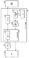
- FIG. 14A It is the figure which represented typically the frame data recorded on four different exposure conditions, and the frame data obtained by synthesize
- FIG. 1 is a block diagram illustrating a configuration example of an image processing apparatus according to the first embodiment.
- the image processing apparatus 100 includes a CPU 101, a DRAM 102, an image input unit 103, an image processing unit 104, and an image output unit 105. These are connected via a bus 106.
- the CPU 101 performs overall control of arithmetic processing and the operation of each unit of the image processing apparatus 100 by reading and executing a control program stored in a ROM (not shown).
- the DRAM 102 is a readable / writable memory, and is a storage medium for temporarily storing various data such as frame data.
- the image input unit 103 stores captured image data (frame data) acquired by an imaging element such as a CMOS sensor in the DRAM 102.
- the image processing unit 104 performs predetermined image processing including NR processing and rotation processing on the frame data of the image input by the image input unit 103, and stores the frame data after the image processing in the DRAM 102.
- the image output unit 105 transfers the frame data after the image processing via a network or records it on an external storage medium such as a USB or SD card.
- FIG. 2 is a block diagram illustrating a configuration example of the image processing unit 104 according to the present embodiment.
- the image processing unit 104 includes a pre-processing unit 201, a cyclic NR processing unit 203, a first inversion processing unit 202, and a second inversion processing unit 204.
- the pre-processing unit 201, the cyclic NR processing unit 203, the first inversion processing unit 202, and the second inversion processing unit 204 of the image processing unit 104 are realized by dedicated circuits.
- a surveillance camera hung from the ceiling can shoot wide surroundings by freely moving the tilt of the camera from about 0 degrees to nearly 180 degrees in a direction perpendicular to the ceiling.
- the subject that appears on the image sensor is turned upside down when the tilt of the camera with respect to the ceiling is 90 degrees or more and when it is less than 90 degrees.
- the pre-processing unit 201 reads the frame data 200 from the DRAM 102 and performs predetermined image processing. Examples of image processing performed by the pre-processing unit 201 include filter processing and color conversion processing, but are not limited thereto.
- the cyclic NR processing unit 203 can receive the frame data from the pre-processing unit 201 without going through the DRAM 102. That is, the cyclic NR processing unit 203 receives frame data that has not been subjected to inversion processing or rotation processing from the upstream processing unit 201. In the present embodiment, it is assumed that the data processing performed by the pre-processing unit 201 and the cyclic NR processing unit 203 is performed by raster scanning on the frame data. It may be performed by rectangular scanning such as.
- the cyclic NR processing unit 203 attempts to reduce noise by superimposing the previous frame data received from the first inversion processing unit 202 on the frame data received from the pre-processing unit 201.
- Each of the first inversion processing unit 202 and the second inversion processing unit 204 can switch ON / OFF of the inversion processing between frames according to parameters individually set by the CPU 101.
- the second inversion processing unit 204 includes an SRAM that stores data for one line of frame data (image data). Then, when the inversion process is set to ON, the second inversion processing unit 204 temporarily stores the input data in the SRAM, and outputs the frame data 205 inverted in line units. On the other hand, when the inversion processing is set to OFF, the second inversion processing unit 204 outputs the input data as it is without inversion.
- the first inversion processing unit 202 performs the same operation.
- the CPU 101 when switching ON / OFF of inversion between frames from OFF to ON, the CPU 101 performs the second inversion processing before the processing of the first frame after switching (herein, simply referred to as the first frame). A setting is made to turn ON the inversion process for the unit 204. At this time, since the image data of the previous frame stored in the DRAM 102 has not been inverted, the setting of the inversion processing for the first inversion processing unit 202 remains OFF. When the processing for the first frame is completed, the inverted image data for the first frame is stored in the DRAM 102. After the processing of the first frame is completed and before the processing of the second frame, the CPU 101 sets the first inversion processing unit 202 to turn on the inversion processing.
- the inverted image data of the first frame is further inverted (that is, in the original state) and input to the cyclic NR processing unit 203. That is, by further inverting the image data of the first frame stored in the DRAM 102 in the inverted state, the phase of the image data of the second frame before the inversion can be matched.
- the inversion processing performed by the first and second inversion processing units 202 and 204 and the cyclic NR processing performed by the cyclic NR processing unit 203 in the present embodiment will be described in detail.
- FIG. 3 is a diagram showing how the second inversion processing unit 204 stores data in the DRAM 102 when the inversion processing is ON.
- the second inversion processing unit 204 holds the frame data 300 whose noise has been reduced by the cyclic NR processing unit 203 in an internal buffer (SRAM) 301 that stores image data for each line.
- SRAM internal buffer
- the data that has been rearranged in the reverse order of the received pixel order is written into the DRAM 102, whereby the inverted frame data (image for one line) Data).
- Inversion processing is performed by performing such processing on all the lines of the frame data.
- the frame data can be written in the frame memory area on the DRAM 102 in order from the address corresponding to the bottom line of the frame, so that the upside down process can be performed.
- the frame data 302 rotated by 180 degrees can be obtained on the DRAM 102 by changing the write order and the start address of the write destination.
- the inversion processing in the first inversion processing unit 202 is realized by setting the head address read from the DRAM 102 and controlling the transfer order when transferring the read data to the cyclic NR processing unit 203.
- the details of the processing are the same as those of the second inversion processing unit 204, and thus detailed description thereof is omitted.
- the image data held by the first and second inversion processing units 202 and 204 is not limited to line units.
- the unit may be a write burst length unit, thereby reducing the internal buffer (SRAM) of each inversion processing unit.
- SRAM internal buffer
- the second inversion processing unit 204 rotates the image by 180 degrees by controlling the writing order and the start address of the writing destination, the present invention is not limited to this.
- the inversion may be performed by controlling the pixel order including reading, or may be performed by changing the head address.
- the rotation processing may be a combination of the above. The same applies to the first inversion processing unit.
- FIG. 4A is a diagram schematically showing frame data input from the image input unit 103. Assume that the input frame data is input in order from frame data with a smaller number, such as frame 0 (400) ⁇ frame 1 (401) ⁇ frame 2 (402).
- FIG. 4B is a diagram schematically illustrating the cyclic noise reduction process.
- Frame data 404 received from the pre-processing unit 201 is a processing target frame (hereinafter referred to as a processing frame), and frame data 403 immediately before the processing frame is a reference frame. That is, the reference frame can be said to be a temporally related frame to the processing frame.
- the reference frame is frame data that has already undergone noise removal processing.
- the cyclic NR process is a process for reducing the noise of the processing frame by superimposing the image data of the reference frame on the image data of the processing frame.
- the frame data 405 of the processing frame with reduced noise is used as a reference frame for noise reduction of the next frame data.
- the present embodiment is not limited to this.
- image data several frames before the processing frame may be used as a reference frame, and a plurality of frame data may be referenced for one processing frame.
- the cyclic NR processing unit 203 can receive the frame data after the inversion process through the first inversion processing unit 202 in order of data before the inversion process.
- the memory bandwidth for one frame can be reduced.
- switching between inversion of a processing frame and a reference frame is performed. Even at times, NR processing can be performed.
- FIG. 5 shows the transition of the frame data stored in each area (area A, B, C, D) of the DRAM 102 when the frame data is read from the DRAM 102 and written to the DRAM 102.
- the frames processed by the cyclic NR processing unit 203 are shifted from the frame 1, the frame 2, and the frame 3 as the time advances to T1, T2, and T3.
- a frame before NR processing and before inversion processing is referred to as “frame before NR / before inversion”
- a frame after NR processing and after inversion processing is referred to as “frame after NR / after inversion”.
- region A is a region in which image input unit 103 writes image data of frame 2 before NR / before inversion.
- a region B (501) is a region where the pre-processing unit 201 reads the image data of the frame 1 before / before NR.
- the pre-processing unit 201 transfers the image data that has undergone the pre-processing to the cyclic NR processing unit 203 as a processing frame.
- a region C (502) is a region where the first inversion processing unit 202 reads the frame 0 after NR / after inversion.
- the first inversion processing unit 202 transfers the further inverted image data to the cyclic NR processing unit 203 as a reference frame.
- the second inversion processing unit 204 performs inversion processing on the frame 1 after NR processing received from the cyclic NR processing unit 203, and after NR / after inversion obtained by the inversion processing. This is an area in which frame 1 is written.
- the image processing unit 104 confirms that each process is completed in units of frames, and proceeds to the process for the next frame.
- image data of frame 2 before / before NR processing is stored in region A (510), and the pre-processing unit 201 reads out the image data.
- the data is transferred to the cyclic NR processing unit 203.
- the image data before the NR / inversion of the frame 3 is written by the image input unit 103 by overwriting the image data of the frame 1.
- the image data of frame 2 after NR / inverted is written by the second inversion processing unit 204 in the form of overwriting the data of frame 0.
- Area D (513) stores the image data of frame 1 after NR / after inversion, and the first inversion processing unit 202 reads out the image data and transfers it to the cyclic NR processing unit 203.
- the areas A and B, the areas C and D similarly operate as a double buffer, and reading and writing are switched. By doing this, it is possible to reduce the waiting time for completion of the preceding process and the succeeding process in each processing unit, and to increase the speed by performing parallel processing.
- the cyclic processing referring to a plurality of frames and the rotation processing are continuously performed, the number of times the frame data is written to the memory is reduced, and the memory bandwidth and the memory area to be used are reduced. Can be reduced.
- FIG. 6 is a block diagram showing a configuration of the image processing unit 104 in the present embodiment.
- the image processing unit 104 includes a pre-stage processing unit 601, a cyclic NR processing unit 603, a first geometric transformation processing unit 602, and a second geometric transformation processing unit 604.
- the processes of the upstream processing unit 601 and the cyclic NR processing unit 603 are the same as the processes of the upstream processing unit 201 and the cyclic NR processing unit 203 in the first embodiment, respectively. Therefore, the description is omitted.
- the second geometric transformation processing unit 604 performs geometric transformation processing on the frame data after NR processing received from the cyclic NR processing unit 603, and stores it in the DRAM 102.
- the rotation angle of the frame data before the geometric transformation processing by the second geometric transformation processing unit 604 is the first rotational angle
- the frame after the geometric transformation processing by the second geometric transformation processing unit 604 is used.
- the rotation angle of the data is the second rotation angle.
- the first geometric transformation processing unit 602 performs geometric transformation processing on the frame data stored at the second rotation angle stored on the DRAM 102 so as to have the first rotation angle, and performs cyclic NR processing. This is input to the unit 603 as reference data.
- first and second geometric transformation processing units 602 and 604 switch between performing the geometric transformation processing on the input data and outputting it as it is or not according to the flag set by the CPU 101 for each frame. Can do.
- a method of geometric transformation processing generally performed there is a realization method by coordinate calculation such as affine transformation.
- affine transformation a method by coordinate calculation such as affine transformation.
- FIG. 7 is a diagram illustrating an example of the configuration and data flow of the second geometric transformation processing unit 604.
- the second geometric transformation processing unit 604 includes an internal buffer 702, an output coordinate calculation unit 703, a parameter holding unit 704, and a data output unit 705.
- the CPU 101 stores the frame data of the first rotation angle in the parameter holding unit 704 of the second geometric conversion processing unit 604, and the second rotation angle of the frame data of the first rotation angle. Set parameters to convert to frame data.
- the second geometric transformation processing unit 604 calculates an affine coefficient based on the parameter stored in the parameter holding unit 704. Alternatively, the CPU 101 may calculate an affine coefficient and set it in the parameter holding unit 704.
- the output coordinate calculation unit 703 obtains output coordinates by performing matrix calculation on the coordinate data 701 received from the cyclic NR processing unit 603 based on affine coefficients, and outputs output coordinate data 706 indicating the obtained output coordinates. Transfer to the data output unit 705.
- the pixel data 700 received from the cyclic NR processing unit 603 is temporarily stored in the internal buffer 702 and then transferred to the data output unit 705 in synchronization with the corresponding output coordinate data 706 calculated by the output coordinate calculation unit 703. Is done.
- the data output unit 705 writes the pixel data 700 at a memory address corresponding to the received output coordinate data 706.
- the data output unit 705 When the output coordinate data 706 is not on the coordinate grid point, the data output unit 705 performs an interpolation calculation based on the peripheral pixel values held in the internal buffer 702, and outputs the pixel data obtained by the interpolation calculation The data is output to the memory address corresponding to the coordinate data 706. Thereby, the geometrically converted frame data can be stored in the DRAM 102. In addition, since the data output unit 705 has a write buffer, a plurality of pixels can be collectively written to the DRAM 102 by continuous transfer, and the processing speed can be increased.
- FIG. 8 is a diagram illustrating an example of the configuration and data flow of the first geometric transformation processing unit 602.
- the first geometric transformation processing unit 602 includes an internal buffer 801, a data reading unit 802, a data output unit 803, a read coordinate calculation unit 805, and a parameter holding unit 806.
- the CPU 101 sets the first rotation angle from the frame data of the second rotation angle to the parameter holding unit 806 of the first geometric conversion processing unit 602, and the first rotation angle from the frame data of the second rotation angle. Set parameters to convert to frame data.
- the first geometric transformation processing unit 602 calculates an affine coefficient based on the parameter stored in the parameter holding unit 806. Alternatively, the CPU 101 may calculate an affine coefficient and set it in the parameter holding unit 806.
- the read coordinate calculation unit 805 performs matrix calculation on the coordinate data received from the pre-processing unit 601 or the coordinate data counted based on the parameters set in the parameter holding unit 806 based on the affine coefficients.
- the readout coordinates are obtained, and readout coordinate data 804 indicating the readout coordinates is output to the data readout unit 802.
- the data reading unit 802 receives the read coordinate data 804 and reads the pixel data 800 from the corresponding memory address.
- the data reading unit 802 has an internal buffer 801 that holds pixel data received from the DRAM 102 by continuous transfer, and when pixel data corresponding to the read coordinate data 804 exists in the internal buffer, reading to the DRAM 102 is performed. The command can be omitted.
- the surrounding pixel data is also read into the internal buffer, and the calculated pixel data is output by performing an interpolation operation.
- the data output unit 803 outputs the pixel data received from the data reading unit 802 to the cyclic NR processing unit 603.
- the configuration example in the present embodiment has been described above.
- the configuration in which the complementing process is performed in the data output unit 705 and the data reading unit 802 is shown, but the geometric transformation process in the present embodiment is preferably a reversible transformation that does not require the complementing process.
- the structure which performs the rotation process by geometric transformation was shown, this embodiment is not restricted to it, The scaling and deformation
- the second geometric transformation processing unit 604 receives the frame data having the first scaling factor or the first shape from the cyclic NR processing unit 603, and receives the frame having the second scaling factor or the second shape. It is converted into data and stored in the DRAM 102.
- the first geometric transformation processing unit 602 performs geometric transformation processing on the frame data stored in the DRAM 102, and the cyclic NR processing unit 603 converts the frame data converted into the first scaling factor or the first shape. As a reference frame.
- the present embodiment even when the cyclic processing referring to a plurality of frames and the geometric transformation processing are continuously performed, the number of times frame data is written to the memory is reduced, and the memory bandwidth to be used is reduced. Memory area can be reduced.
- FIG. 9 is a block diagram illustrating a configuration example of the image processing unit 104 in the present embodiment.
- the image processing unit 104 includes a pre-stage processing unit 901, a cyclic NR processing unit 903, a first LUT conversion unit 902, and a second LUT conversion unit 904.
- the processes of the pre-processing unit 901 and the cyclic NR processing unit 903 are the same as the processes of the pre-processing unit 201 and the cyclic NR processing unit 203 in the first embodiment, respectively.
- the description is omitted.
- the first and second LUT conversion units 902 and 904 internally have an SRAM for storing a table value to be referred to.
- the CPU 101 writes the table value into the SRAM of each of the first and second LUT conversion units 902 and 904.
- This table value is written as a one-dimensional table, for example, and used when performing deformation processing according to the distance from the image center point.
- the first and second LUT converters 902 and 904 can switch whether the input data is output after being subjected to LUT conversion or output as it is, according to a flag set by the CPU 101 for each frame. is there.
- configurations of the first LUT conversion unit 902 and the second LUT conversion unit 904 will be described with reference to FIGS. 10 and 11.
- FIG. 10 is a diagram illustrating an example of the configuration and data flow of the second LUT conversion unit 904.
- the second LUT conversion unit 904 includes an internal buffer 1002, an output coordinate calculation unit 1003, an LUT 1004, and a data output unit 1005.
- the output coordinate calculation unit 1003 selects the table value of the LUT 1004 to be referenced for each pixel from the coordinate data 1001 received from the cyclic NR processing unit 903 and the predetermined center point coordinates. Further, the output coordinate calculation unit 1003 calculates the output coordinate data 1006 by superimposing the referenced table value on the coordinate data, and transfers the calculated output coordinate data 1006 to the data output unit 1005.
- the pixel data 1000 received from the cyclic NR processing unit 903 is temporarily stored in the internal buffer 1002, and then transferred to the data output unit 1005 in synchronization with the corresponding output coordinate data 1006 calculated by the output coordinate calculation unit 1003. Is done.
- the data output unit 1005 writes the pixel data 1000 to the memory address corresponding to the received output coordinate data 1006.
- the other operations of the internal buffer 1002 and the data output unit 1005 are the same as those of the internal buffer 702 and the data output unit 705 in the second embodiment, and are therefore omitted.
- FIG. 11 is a diagram illustrating an example of the configuration and data flow of the first LUT conversion unit 902.
- the first LUT conversion unit 902 includes an internal buffer 1101, a data reading unit 1102, a data output unit 1103, a read coordinate calculation unit 1105, and an LUT 1106.
- the read coordinate calculation unit 1105 is predetermined as coordinate data received from the pre-processing unit 901 or coordinate data counted internally (coordinate data for the pixel data 1100 read from the memory address corresponding to the read coordinate data 1104).
- the table value of the LUT 1106 to be referred is selected for each pixel from the center point coordinates. Further, the readout coordinate is calculated by superimposing the referenced table value on the coordinate data, and transferred to the data readout unit 1102.
- the CPU 101 performs the conversion process of the first LUT conversion unit 902 on the frame data after the conversion process of the second LUT conversion unit 904 so as to match the frame data before the LUT conversion process in advance. Set. By doing so, it is possible to continue the cyclic NR process and the LUT conversion process without holding the image data after the NR process and before the LUT conversion on the DRAM 102. Since the processing of the data reading unit 1102 including the internal buffer 1101 and the data output unit 1103 is the same as that of the data reading unit 802 and the data output unit 803 in the second embodiment, detailed description thereof is omitted.
- a method of calculating coordinates with reference to a one-dimensional table has been shown, but coordinates may be calculated with reference to a two-dimensional table or a three-dimensional table. Further, the method of calculating from the table reference value is not limited to the coordinate calculation.
- the attribute value may be held in the LUT and the correction process corresponding to the attribute may be switched.
- a configuration in which geometric transformation, parallel movement, and correction processing are performed simultaneously is also conceivable.
- the configuration in which the first LUT conversion unit 902 and the second LUT conversion unit 904 hold separate LUTs has been described, but one LUT is held in the image processing unit 104.
- the first and second LUT conversion units 902 and 904 may share the LUT.
- this embodiment can be easily realized by referring to the same LUT and performing the same calculation on the output coordinate and the read coordinate.
- the present embodiment even when cyclic processing referring to a plurality of frames and LUT conversion processing are continuously performed, the number of times frame data is written to the memory is reduced, and the memory bandwidth to be used is reduced. Memory area can be reduced.
- the image processing is performed by referring to the temporally previous frame data as represented by cyclic NR processing. did.
- a configuration is performed in which processing for combining frame data generated under a plurality of different conditions, such as HDR (High Dynamic Range) processing, is performed.
- HDR processing is a technique that can express a wider dynamic range by combining image data generated under a plurality of exposure conditions.
- frame data with a plurality of composition conditions is output based on frame data recorded under four different exposure conditions, and the output data is further inverted.
- the present embodiment can be applied to image processing that refers to a plurality of frame data, and the image to be processed may be any image.
- the present invention can be applied to a case where noise reduction, resolution conversion, and HDR processing are performed on a plurality of still images obtained by photographing the same scene with a multi-lens camera or the like by referring to the plurality of still images.
- the inversion processing may be geometric transformation processing, LUT transformation processing, or the like as described in the first to third embodiments.
- FIGS. 12 and 13 the configuration and processing flow in this embodiment will be described with reference to FIGS. 12 and 13.
- FIG. 12 is a block diagram illustrating a configuration example of the image processing unit 104 in the present embodiment.
- the image processing unit 104 includes a first inversion processing unit 1200, a second inversion processing unit 1202, and an image composition unit 1201.
- the image composition unit 1201 performs composition processing to superimpose two input frame data for each pixel.
- the second inversion processing unit 1202 receives the output data of the image composition unit 1201, performs inversion processing, and writes it in the DRAM 102.
- the first inversion processing unit 1200 reads the frame data from the DRAM 102, performs inversion processing, and transfers the frame data to the image composition unit 1201. Since the processes performed by the first and second inversion processing units 1200 and 1202 are the same as those of the first and second inversion processing units 202 and 204 in the first embodiment, details are omitted.
- FIG. 13 is a diagram schematically showing frame data (F1300 to F1303) recorded under four different exposure conditions and frame data (F1304 to F1306) obtained by combining them.
- Frame data F1300 to F1303 are data stored in the DRAM 102 by the image input unit 103.
- frame data synthesized under three different conditions is generated in an inverted state. That is, it is assumed that frame data F1304 obtained by combining frame data F1300 and frame data F1301 is generated in an inverted state. Further, it is assumed that frame data F1305 obtained by combining frame data F1300 to F1302 is generated in an inverted state. Further, it is assumed that frame data F1306 obtained by combining frame data F1300 to F1303 is generated in an inverted state.
- the image composition unit 1201 reads out the frame data F1300 and the frame data F1301 from the DRAM 102, and stores the pixel data subjected to the composition processing in the DRAM 102 via the second inversion processing unit 1202.
- the inverted frame data F1304 can be held on the DRAM 102.
- frame data F1305 is generated.
- the frame data F1305 can be replaced by synthesis of the frame data F1304 and the frame data F1302.
- the frame data F1304 stored in the DRAM 102 is inverted frame data that is finally required.
- the frame data F1304 before inversion should be held in the DRAM 102 in order to shorten the composition processing.
- storing both the inverted frame data and the frame data before being inverted in the DRAM 102 increases the memory bandwidth and the memory usage area. Therefore, in the present embodiment, when the first inversion processing unit 1200 is provided and the inverted frame data on the DRAM 102 is used for the composition processing, the image is inverted again through the first inversion processing unit 1200 and then the image. Input to the combining unit 1201. By doing so, it is possible to shorten the synthesis process while suppressing the number of times frame data is written to the memory (DRAM 102). In the case shown in FIG. 13, also in the generation of the frame data F 1306, the frame data F 1305 stored by being inverted is read through the first inversion processing unit 1200, and the frame data F 1303 is directly read from the DRAM 102. By doing this, the same effect can be obtained.
- the number of times frame data is written to the memory can be reduced and used even when the process of superimposing the frame data generated under different conditions and the inversion process are continuously performed.
- Memory bandwidth and memory area can be reduced.
- each processing of each component of the image processing unit 104 is implemented by hardware has been described.
- the image processing unit 104 is not limited to hardware implementation, and is effective even when, for example, a part or all of the image processing unit 104 is implemented by software using a CPU.
- an operation when all the processes of the image processing unit 104 are implemented by software will be described.
- each configuration of the image processing unit 104 illustrated in FIG. 1 is a functional configuration realized by the CPU 101.
- the case where the image processing unit 104 performs cyclic NR processing and inversion processing is described as an example.
- Absent. 14A and 14B are flowcharts showing the processing executed by the image processing unit 104 as a whole.
- a CPU (not shown) dedicated to the image processing unit 104 reads out and executes a program that realizes processing according to the flow shown in FIGS. 14A and 14B.
- the CPU that performs image processing of the image processing unit 104 is assumed to be a CPU different from the CPU 101, but the CPU 101 may perform it.
- the image processing unit 104 performs processing in units of frames along the flow shown in FIGS. 14A and 14B.
- the image processing unit 104 receives various setting values necessary for the frame processing from the CPU 101 at the start of the frame processing (step S1400).
- the set value here includes the number of pixels to be processed at once, ON / OFF of inversion processing on the reading side, and ON / OFF of inversion processing on the writing side.
- the image processing unit 104 reads out the pixel data for the set number of pixels from the frame data written out to the memory by the image input unit 103 (step S1401). Image processing is performed (step S1402). This is the pixel data of the processing frame.
- the image processing unit 104 switches the setting of the readout address of the frame to be referenced according to ON / OFF of the inversion processing on the readout side set by the CPU 101 (step S1403).
- the image processing unit 104 sets the reading address so that the pixel data of the reference frame stored in the memory can be read from the reverse in both the main scanning direction and the sub scanning direction. (Step S1404).
- the image processing unit 104 may set a read address so that it can be read from an address 32 bytes before the last address where the frame data is stored.
- the image processing unit 104 sets a reading address so that the pixel data can be read as it is in the same order as the processing frame reading order (step S1405).
- the image processing unit 104 reads pixel data of reference frames for a predetermined number of pixels based on the set read address (step S1406).
- the image processing unit 104 superimposes the pixel data of the corresponding reference frame on the pixel data of the processing frame, and performs cyclic NR processing (step S1407).
- the image processing unit 104 writes the pixel data after the cyclic NR process to the memory.
- the image processing unit 104 switches the setting of the writing address according to the ON / OFF setting of the reversal processing on the writing side set from the CPU (step S1408).
- the image processing unit 104 sets a write address so that the pixel data can be inverted and written to the memory (step S1409).
- the image processing unit 104 sets a write address so that it can be written in the memory in the raster order as it is (step S1410).
- the image processing unit 104 writes the pixel data after the cyclic NR process in the memory based on the set write address (step S1411).
- the image processing unit 104 repeatedly performs steps S1401 to S1411 until the processing for one frame is completed, confirms that the processing for one frame is completed, and completes the frame processing (step S1412). ).
- steps S1401 to S1411 until the processing for one frame is completed, confirms that the processing for one frame is completed, and completes the frame processing (step S1412). ).
- the present embodiment even when cyclic NR processing and inversion processing are implemented by software, the number of times frame data is written to memory is reduced, and the memory bandwidth and memory area to be used are reduced. can do.
- the present invention supplies a program that realizes one or more functions of the above-described embodiments to a system or apparatus via a network or a storage medium, and one or more processors in a computer of the system or apparatus read and execute the program This process can be realized. It can also be realized by a circuit (for example, ASIC) that realizes one or more functions.
- a circuit for example, ASIC
Landscapes
- Engineering & Computer Science (AREA)
- Multimedia (AREA)
- Signal Processing (AREA)
- Physics & Mathematics (AREA)
- General Physics & Mathematics (AREA)
- Theoretical Computer Science (AREA)
- Computer Vision & Pattern Recognition (AREA)
- Image Processing (AREA)
- Studio Devices (AREA)
Abstract
フレームメモリを使用して複数フレームのデータを参照する処理と、回転処理とを続けて行う画像処理装置において、メモリへのフレームデータの書き出し・読み出しが多数発生し、使用するメモリ帯域及び領域が増大する。第一の処理対象のフレームの画像データを入力する入力手段と、メモリに格納されている、第一の処理対象のフレームに関連するフレームである第一の参照フレームの画像データを反転して出力する第一の反転処理手段と、入力手段で入力された第一の処理対象のフレームの画像データに対して、第一の反転処理手段によって反転された第一の参照フレームの画像データに基づいて画像処理を行なう画像処理手段と、画像処理手段によって画像処理された第一の処理対象のフレームの画像データを、第二の処理対象のフレームに関連する第二の参照フレームとして、反転してメモリに格納する第二の反転処理手段とを有する。
Description
本発明は、フレーム単位の複数の画像データを用いて画像処理を行なう技術に関する。
ビデオカメラ等の撮像装置では、映像信号に含まれるノイズ成分を低減した高画質映像を得るために、ノイズ除去(ノイズリダクションとも呼び、NRと略す)処理が行われている。NR処理の中で、過去のフレームデータを巡回的に用いて、時間方向に変化するフレームデータの差分情報に基づいてノイズを除去する方法を、巡回型NR処理と呼ぶ。巡回型NR処理は、アルゴリズムが簡単なわりに効果が大きい。
また、画像を回転や反転する幾何変換処理が、基本画像処理として様々な場面で用いられている。例えば、ビデオカメラなどでは、ディスプレイに画像を表示する際に、ジャイロセンサ等で傾きを検出し、検出された傾きに合わせて、表示する画像を回転する、といった処理が行われている。また、接地面に対して180度近く回転できる監視カメラも存在する。そのような監視カメラにおいては、カメラの傾きに合わせて、表示する画像を180度回転させる必要がある。このような回転処理を実現する場合、画像データを一時的にメモリ(DRAM)に格納することが多い。メモリへ書き込む際の書き込みアドレスを制御することで、あるいは、メモリから読み出す際の読み出しアドレスを制御することで、内部バッファ(SRAM)の使用を避け、回路規模を削減できる。
特許文献1では、幾何変換処理及び巡回型NR処理を組み合わせた処理を行う装置が開示されている。具体的には、特許文献1に開示された方法では、注目画面と、当該注目画面よりも前の基準画面との間の平行移動量を算出すると共に、基準画面に対する注目画面の回転角度を算出する。そして、メモリに格納されている注目画面の画素データを、読み出しアドレスを制御することで、算出した平行移動量だけ移動すると共に、算出した回転角度だけ回転させるように読み出す。そして、読み出した注目画面の画素データと、基準画面の画素データとを用いて巡回型NR処理を行う。
しかしながら、上述したような巡回型NRに代表される、フレームデータを格納するためのメモリを必要とする処理と、反転処理や回転処理とを続けて行う場合、メモリに対する多数のフレームデータの書き込みや読み出しが発生してしまう。特許文献1に開示された方法では、注目画面の画素データと基準画面の画素データとを共にメモリから読み出しており、NR処理後の画素データもメモリに書き出している。このように、多数のフレームデータを、メモリを介して処理すると、メモリ帯域やメモリ領域を多く消費し、システム性能の劣化とコスト増加を招いてしまう。特に、昨今の映像処理においては、4k2kや8k4kの解像度に対応させた大容量のフレームデータを扱うシステムが増えており、その影響は多大なものとなる。
本発明に係る画像処理装置は、フレーム単位の画像データを格納する領域を有するメモリを備えた画像処理装置であって、第一の処理対象のフレームの画像データを入力する入力手段と、メモリに格納されている、第一の処理対象のフレームに関連するフレームである第一の参照フレームの画像データを反転して出力する第一の反転処理手段と、入力手段で入力された第一の処理対象のフレームの画像データに対して、第一の反転処理手段によって反転された第一の参照フレームの画像データに基づいて画像処理を行なう画像処理手段と、画像処理手段によって画像処理された第一の処理対象のフレームの画像データを、第二の処理対象のフレームに関連する第二の参照フレームとして、反転してメモリに格納する第二の反転処理手段とを有することを特徴とする。
本発明によれば、フレームデータを格納するメモリを使用して複数フレームのデータを参照する処理と、回転処理とを続けて行う画像処理装置において、使用するメモリ帯域・メモリ領域を削減できる。
以下、本発明を実施するための形態を詳細に説明する。なお、以下の実施形態は本発明を限定するものではなく、また、本実施形態で説明されている特徴の組み合わせの全てが本発明の解決手段に必須のものとは限らない。
[第1実施形態]
本実施形態は、撮像装置などに代表される、動画像データを扱う画像処理装置に関する。図1は、第1実施形態における画像処理装置の構成例を示すブロック図である。画像処理装置100は、CPU101、DRAM102,画像入力部103、画像処理部104、および画像出力部105を有する。これらは、バス106を介して接続されている。CPU101は、不図示のROMに格納された制御プログラムを読み出し実行することにより、演算処理や画像処理装置100各部の動作を統括的に制御する。DRAM102は、読み出し及び書き込み可能なメモリであり、フレームデータなどの各種データを一時的に格納するための記憶媒体である。画像入力部103は、CMOSセンサなどの撮像素子が取得した撮像画像のデータ(フレームデータ)をDRAM102に格納する。画像処理部104は、画像入力部103が入力した画像のフレームデータに対して、NR処理や回転処理を含む所定の画像処理を行い、画像処理後のフレームデータをDRAM102に格納する。画像出力部105は、画像処理後のフレームデータを、ネットワークを介して転送したり、USBやSDカードなどの外部記憶媒体に記録したりするものである。
本実施形態は、撮像装置などに代表される、動画像データを扱う画像処理装置に関する。図1は、第1実施形態における画像処理装置の構成例を示すブロック図である。画像処理装置100は、CPU101、DRAM102,画像入力部103、画像処理部104、および画像出力部105を有する。これらは、バス106を介して接続されている。CPU101は、不図示のROMに格納された制御プログラムを読み出し実行することにより、演算処理や画像処理装置100各部の動作を統括的に制御する。DRAM102は、読み出し及び書き込み可能なメモリであり、フレームデータなどの各種データを一時的に格納するための記憶媒体である。画像入力部103は、CMOSセンサなどの撮像素子が取得した撮像画像のデータ(フレームデータ)をDRAM102に格納する。画像処理部104は、画像入力部103が入力した画像のフレームデータに対して、NR処理や回転処理を含む所定の画像処理を行い、画像処理後のフレームデータをDRAM102に格納する。画像出力部105は、画像処理後のフレームデータを、ネットワークを介して転送したり、USBやSDカードなどの外部記憶媒体に記録したりするものである。
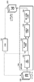
図2は、本実施形態による画像処理部104の構成例を示すブロック図である。画像処理部104は、前段処理部201、巡回型NR処理部203、第一の反転処理部202、および第二の反転処理部204を有する。本実施形態において画像処理部104の、前段処理部201、巡回型NR処理部203、第一の反転処理部202、および第二の反転処理部204は、専用の回路によって実現されている。
ここで、このような構成を採用する撮像装置について、監視カメラを例に挙げて説明する。天井から吊るされる監視カメラには、カメラの傾きを、天井に対して垂直方向に約0度から180度近くまで自由に可動させることで、周囲を広く撮影できるものがある。このような監視カメラでは、天井に対するカメラの傾きが90度以上の場合と90度未満の場合とで、撮像素子に写る被写体が上下反転する。監視カメラを可動させる過程で、ユーザーが違和感のない画像を認識するためには、順次入力されるフレームの途中で、出力する画像データを180度回転する必要がある。これは、フレーム間で反転や回転のON/OFFを切り替えることで実現される。しかし、例えば巡回型NR処理のように前フレームを参照する処理では、処理対象とするフレームに対して前フレームの画像データが反転や回転していない状態で、前フレームの画像データを読みだす必要がある。特許文献1で示される巡回型NRの手法では、回転のON/OFFを切り替える前後において、画像データの回転の有無が異なってしまうため、上述したような監視カメラのユースケースに適用できない。また、巡回型NR処理と回転処理とのどちらが先に行われても、フレームデータのメモリに対する読み出しや書き出しは多くなるため、使用するメモリ帯域やメモリ領域を増大させてしまう。以下では、上述した課題を解決する本実施形態の構成について、図2を用いて詳細に説明する。
本実施形態における画像処理部104は、前段処理部201がDRAM102からフレームデータ200を読み出し、所定の画像処理を実施する。前段処理部201で実施される画像処理として、例えばフィルタ処理や色変換処理などが挙げられるが、これらに限られるものではない。巡回型NR処理部203は、前段処理部201からのフレームデータを、DRAM102を介さずに受信することができる。すなわち、巡回型NR処理部203は、前段処理部201から、反転処理や回転処理がなされていない、フレームデータを受信する。本実施形態では、前段処理部201と巡回型NR処理部203とで行なわれるデータの処理を、フレームデータに対してラスタ走査で行うことを想定しているが、当該データの処理は、ブロック処理等の矩形走査で行われてもよい。巡回型NR処理部203は、前段処理部201から受信するフレームデータに、第一の反転処理部202から受信する、時間的にひとつ前のフレームデータを重ね合わせることでノイズ低減を図る。
第一の反転処理部202および第二の反転処理部204はそれぞれ、CPU101から個別に設定されるパラメータにより、フレーム間で反転処理のON/OFFを切り換えることができる。例えば、第二の反転処理部204は、フレームデータ(画像データ)の1ライン分のデータを格納するSRAMを有する。そして、第二の反転処理部204は、反転処理がONに設定されている場合、一旦入力データをSRAMにため込み、ライン単位に反転したフレームデータ205を出力する。一方、第二の反転処理部204は、反転処理がOFFに設定されている場合、入力データを反転せずにそのまま出力する。第一の反転処理部202も同様の動作を行なう。
そして、例えば、フレーム間で反転のON/OFFをOFFからONに切り換える場合、切り換え後における1フレーム目(ここでは、単に1フレーム目と呼ぶ)の処理の前に、CPU101から第二の反転処理部204に対して、反転処理をONにする設定を行う。この時、DRAM102に格納されている前フレームの画像データは反転処理されていないため、第一の反転処理部202に対する反転処理の設定をOFFのままとする。そして、1フレーム目の処理が完了すると、反転処理された1フレーム目の画像データがDRAM102に格納される。1フレーム目の処理が完了した後、2フレーム目の処理の前に、CPU101は第一の反転処理部202に対して反転処理をONにする設定を行う。これにより、反転処理された1フレーム目の画像データがさらに反転処理されて(つまりオリジナルの状態で)巡回型NR処理部203に入力されることになる。つまり、反転処理された状態でDRAM102に格納されている、1フレーム目の画像データをさらに反転させることで、反転前の2フレーム目の画像データと位相を合わせることができる。以下、本実施形態における、第一および第二の反転処理部202、204が行なう反転処理と、巡回型NR処理部203が行なう巡回型NR処理とに関して、それぞれ詳細に説明する。
[反転処理]
図3は、第二の反転処理部204が、反転処理ON時にDRAM102にデータを格納する様子を示す図である。第二の反転処理部204は、巡回型NR処理部203でノイズ低減されたフレームデータ300を、1ライン毎に画像データを格納する内部バッファ(SRAM)301に保持する。第二の反転処理部204が内部バッファ分のデータを受け取り終えた後、受信した画素順の逆の順序に並び変えたデータをDRAM102に書き込むことで、1ライン分の反転されたフレームデータ(画像データ)が得られる。このような処理をフレームデータの全てのラインに対して行なうことで反転処理が行なわれる。また、DRAM102上のフレームメモリ領域の中で、フレームの最下部のラインに相当するアドレスから順にフレームデータを書き込むことで、上下反転処理も合わせて行うことができる。このように、書き込み順と書き込み先の先頭アドレスを変更することで、DRAM102上に180度回転したフレームデータ302を得ることができる。
図3は、第二の反転処理部204が、反転処理ON時にDRAM102にデータを格納する様子を示す図である。第二の反転処理部204は、巡回型NR処理部203でノイズ低減されたフレームデータ300を、1ライン毎に画像データを格納する内部バッファ(SRAM)301に保持する。第二の反転処理部204が内部バッファ分のデータを受け取り終えた後、受信した画素順の逆の順序に並び変えたデータをDRAM102に書き込むことで、1ライン分の反転されたフレームデータ(画像データ)が得られる。このような処理をフレームデータの全てのラインに対して行なうことで反転処理が行なわれる。また、DRAM102上のフレームメモリ領域の中で、フレームの最下部のラインに相当するアドレスから順にフレームデータを書き込むことで、上下反転処理も合わせて行うことができる。このように、書き込み順と書き込み先の先頭アドレスを変更することで、DRAM102上に180度回転したフレームデータ302を得ることができる。
一方、第一の反転処理部202における反転処理は、DRAM102から読み出す先頭アドレスの設定と、読み出したデータを巡回型NR処理部203へ転送するときの転送順の制御によって実現される。処理の詳細については第二の反転処理部204と同等の処理であるため詳述は省略する。
なお、第一および第二の反転処理部202、204が保持する画像データは、ライン単位に限られるものではない。例えば書き込みバースト長単位でもよく、これにより、各反転処理部が有する内部バッファ(SRAM)を削減することができる。また、第二の反転処理部204が書き出し順と書き出し先の先頭アドレスを制御することで画像を180度回転する一例を挙げたが、それに限られるものではない。読み出しも含めた、画素順の制御による反転でもよいし、先頭アドレスの変更による反転でもよい。また、それぞれを組み合わせた回転処理であってももちろんよい。第一の反転処理部についても同様である。
[巡回型NR処理]
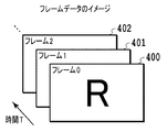
図4Aは、画像入力部103から入力されるフレームデータを模式的に表した図である。入力されるフレームデータは、フレーム0(400)→フレーム1(401)→フレーム2(402)というように、数字が小さいフレームデータから順に入力されるものとする。図4Bは、巡回型ノイズ低減処理を模式的に表した図である。前段処理部201から受信したフレームデータ404を処理対象のフレーム(以下、処理フレームと呼ぶ)とし、処理フレームに対してひとつ前のフレームデータ403を参照フレームとする。つまり、参照フレームは、処理フレームと時間的に関連するフレームとも言える。参照フレームは既にノイズ除去処理されたフレームデータである。巡回型NR処理は、処理フレームの画像データに対して、参照フレームの画像データを重ね合わせることで処理フレームのノイズ低減を図る処理である。ノイズ低減された処理フレームのフレームデータ405は、次のフレームデータをノイズ低減するための参照フレームとして使われる。なお、巡回型NR処理の一例を述べたが、本実施形態はそれに限定されるものではない。例えば、処理フレームに対して数フレーム前の画像データを参照フレームとしてもよく、ひとつの処理フレームに対して複数のフレームデータを参照してもよい。
図4Aは、画像入力部103から入力されるフレームデータを模式的に表した図である。入力されるフレームデータは、フレーム0(400)→フレーム1(401)→フレーム2(402)というように、数字が小さいフレームデータから順に入力されるものとする。図4Bは、巡回型ノイズ低減処理を模式的に表した図である。前段処理部201から受信したフレームデータ404を処理対象のフレーム(以下、処理フレームと呼ぶ)とし、処理フレームに対してひとつ前のフレームデータ403を参照フレームとする。つまり、参照フレームは、処理フレームと時間的に関連するフレームとも言える。参照フレームは既にノイズ除去処理されたフレームデータである。巡回型NR処理は、処理フレームの画像データに対して、参照フレームの画像データを重ね合わせることで処理フレームのノイズ低減を図る処理である。ノイズ低減された処理フレームのフレームデータ405は、次のフレームデータをノイズ低減するための参照フレームとして使われる。なお、巡回型NR処理の一例を述べたが、本実施形態はそれに限定されるものではない。例えば、処理フレームに対して数フレーム前の画像データを参照フレームとしてもよく、ひとつの処理フレームに対して複数のフレームデータを参照してもよい。
巡回型NR処理部203は、反転処理後のフレームデータを、第一の反転処理部202を介して読み出すことで、反転処理前のデータ順で受信することができる。このような構成にすることで、NR処理後でかつ反転処理前のフレームデータをDRAM102へ格納することを省くことができ、反転処理部202を設けなかった場合に比べて、少なくともフレーム処理毎に1フレーム分のメモリ帯域を削減することができる。また、前述した監視カメラの例のように、フレームの途中で回転のON/OFFを切り換えたい場合においても、本実施形態で説明した構成を採用することで、処理フレームと参照フレームの反転の切り替え時においてもNR処理をすることができる。
続いて、本実施形態で必要なDRAM102上のフレームメモリ領域について説明する。図5には、フレームデータがDRAM102から読み出され、かつ、フレームデータがDRAM102に書き込まれる際に、DRAM102の各領域(領域A,B,C,D)に格納されるフレームデータの推移が示されている。時間がT1、T2、T3と進むにつれて、フレーム1、フレーム2、フレーム3と巡回型NR処理部203が処理をするフレームが移っていくこととする。以下、NR処理前かつ反転処理前のフレームのことを「NR前/反転前のフレーム」、NR処理後かつ反転処理後のフレームのことを「NR後/反転後のフレーム」などと記載する。
フレーム1に対して巡回NR処理が行われるとき(時間T1)、領域A(500)は、画像入力部103がNR前/反転前のフレーム2の画像データを書き込む領域である。領域B(501)は、前段処理部201がNR前/反転前のフレーム1の画像データを読み出す領域である。前段処理部201は、前段処理を行なった画像データを、巡回型NR処理部203へ処理フレームとして転送する。領域C(502)は、第一の反転処理部202がNR後/反転後のフレーム0を読み出す領域である。第一の反転処理部202は、さらに反転処理した画像データを、巡回型NR処理部203へ参照フレームとして転送する。領域D(503)は、第二の反転処理部204が巡回型NR処理部203から受け取ったNR処理後のフレーム1に対して反転処理を行い、反転処理して得られるNR後/反転後のフレーム1を書き込む領域である。画像処理部104は、フレーム単位で各処理が完了したことを確認し、次のフレームの処理へ移る。
フレーム2に巡回NR処理を行うとき(時間T2)、領域A(510)には、NR処理前/反転前のフレーム2の画像データが格納されていて、当該画像データを前段処理部201が読み出し、巡回型NR処理部203へ転送する。領域B(511)には、フレーム1の画像データに上書きするかたちで、画像入力部103によってフレーム3のNR前/反転前の画像データが書き込まれる。領域C(512)には、フレーム0のデータに上書きするかたちで、第二の反転処理部204によってNR後/反転後のフレーム2の画像データが書き込まれる。領域D(513)には、NR後/反転後のフレーム1の画像データが格納されており、当該画像データを第一の反転処理部202が読み出し、巡回型NR処理部203へ転送する。フレーム3に巡回NR処理を行うとき(時間T3)の詳細は省略するが、同様に領域Aと領域B、領域Cと領域Dがダブルバッファとして動作し、読み出しおよび書き込みが入れ換わる。こうすることで、各処理部における、前段の処理や後段の処理の完了待ちを減らし、並行処理して高速化することができる。また、本実施形態では、図5から分かるように、NR処理後かつ反転処理前のフレームデータをDRAM102上に保持する必要がない。そのため、巡回NR処理後と回転処理後のそれぞれにおいて、フレームデータをメモリへ書き出す場合に比べて、使用するメモリ領域を削減することができる。
以上説明したように本実施形態によれば、複数フレームを参照した巡回型処理と、回転処理とを続けて行う場合において、フレームデータをメモリに書き出す回数を削減し、使用するメモリ帯域とメモリ領域を削減することができる。
[第2実施形態]
以下、第2実施形態について説明する。上述した第1実施形態では図2に示すような第一および第二の反転処理部202、204を有し、読み出しおよび書き出しの順序や先頭アドレスの制御により、回転や反転を実現する構成を示した。本実施形態では、幾何変換処理部を有し、巡回型NR処理後のフレームデータに対し、座標演算により回転処理する構成を説明する。
以下、第2実施形態について説明する。上述した第1実施形態では図2に示すような第一および第二の反転処理部202、204を有し、読み出しおよび書き出しの順序や先頭アドレスの制御により、回転や反転を実現する構成を示した。本実施形態では、幾何変換処理部を有し、巡回型NR処理後のフレームデータに対し、座標演算により回転処理する構成を説明する。
図6は、本実施形態における画像処理部104の構成を示すブロック図である。画像処理部104は、前段処理部601、巡回型NR処理部603、第一の幾何変換処理部602、および第二の幾何変換処理部604を有する。本実施形態の画像処理部104において、前段処理部601と巡回型NR処理部603との処理は、それぞれ第1実施形態における前段処理部201と巡回型NR処理部203との処理と同様であるため、説明を省略する。
第二の幾何変換処理部604は、巡回型NR処理部603から受け取ったNR処理後のフレームデータに対して幾何変換処理を行い、DRAM102へ格納する。ここで、後述の説明のため、第二の幾何変換処理部604による幾何変換処理前のフレームデータの回転角を第1の回転角、第二の幾何変換処理部604による幾何変換処理後のフレームデータの回転角を第2の回転角とする。第一の幾何変換処理部602は、DRAM102上に格納された第2の回転角で保存されたフレームデータに対して、第1の回転角となるように幾何変換処理を行い、巡回型NR処理部603へ参照データとして入力する。なお、第一および第二の幾何変換処理部602、604は、フレーム毎にCPU101から設定されるフラグにより、入力データに対して幾何変換処理をして出力するか、そのまま出力するかを切り換えることができる。一般的に行われる幾何変換処理の手法として、アフィン変換のような座標演算による実現方法がある。以下、本実施形態における、アフィン変換を用いた幾何変換処理の詳細を図7と図8を用いて説明する。
図7は、第二の幾何変換処理部604の構成およびデータフローの一例を示す図である。第二の幾何変換処理部604は、内部バッファ702、出力座標演算部703、パラメータ保持部704、およびデータ出力部705を有する。まず、フレーム処理の開始前に、CPU101が、第二の幾何変換処理部604のパラメータ保持部704に、第一の幾何変換処理部604が第1の回転角のフレームデータを第2の回転角のフレームデータに変換するようなパラメータを設定する。第二の幾何変換処理部604は、パラメータ保持部704のパラメータをもとにアフィン係数を算出する。あるいはCPU101がアフィン係数を算出し、パラメータ保持部704に設定してもよい。出力座標演算部703は、巡回型NR処理部603から受信する座標データ701に対してアフィン係数をもとに行列演算を行うことにより出力座標を求め、求めた出力座標を示す出力座標データ706をデータ出力部705へ転送する。巡回型NR処理部603から受信した画素データ700は、内部バッファ702に一旦保持された後、出力座標演算部703によって算出された対応する出力座標データ706と同期して、データ出力部705に転送される。データ出力部705は、受け取った出力座標データ706に対応するメモリアドレスに、画素データ700を書き込む。データ出力部705は、出力座標データ706が座標の格子点上に乗らない場合、内部バッファ702に保持された周辺画素値をもとに補間演算を行い、補間演算によって得られた画素データを出力座標データ706に対応するメモリアドレスに出力する。これにより、幾何変換されたフレームデータをDRAM102へ格納できる。またデータ出力部705は、ライトバッファを有することで、複数画素をまとめて連続転送によりDRAM102へ書き込み、処理の高速化を図ることができる。
図8は、第一の幾何変換処理部602の構成およびデータフローの一例示す図である。第一の幾何変換処理部602は、内部バッファ801、データ読み出し部802、データ出力部803、読み出し座標演算部805、およびパラメータ保持部806を有する。まず、フレーム処理の開始前に、CPU101が、第一の幾何変換処理部602のパラメータ保持部806に、第一の幾何変換処理部602が第2の回転角のフレームデータから第1の回転角のフレームデータに変換するようなパラメータを設定する。第一の幾何変換処理部602は、パラメータ保持部806のパラメータをもとにアフィン係数を算出する。あるいはCPU101がアフィン係数を算出し、パラメータ保持部806に設定してもよい。読み出し座標演算部805は、前段処理部601から受け取る座標データ、あるいはパラメータ保持部806に設定されたパラメータをもとにカウントされる座標データに対してアフィン係数をもとに行列演算を行うことにより、読み出し座標を求めて、該読み出し座標を示す読み出し座標データ804をデータ読み出し部802に出力する。データ読み出し部802は、読み出し座標データ804を受信し、対応するメモリアドレスから、画素データ800を読み出す。ここで、データ読み出し部802は、連続転送によりDRAM102から受信した画素データを保持する内部バッファ801を有し、読み出し座標データ804に対応する画素データが内部バッファに存在する場合は、DRAM102への読み出し命令を省略できる。また、読み出し座標データ804が座標の格子点上に乗らない場合、周辺の画素データも内部バッファに読み出し、補間演算を行い算出した画素データを出力する。データ出力部803は、データ読み出し部802から受け取った画素データを巡回型NR処理部603へと出力する。
以上、本実施形態における構成例を示した。ここでは、データ出力部705やデータ読み出し部802において補完処理を行う構成を示したが、本実施形態における幾何変換処理は、補完処理を必要としない可逆変換であることが望ましい。また、幾何変換による回転処理を行なう構成を示したが、本実施形態はそれに限られるものではなく、幾何変換による変倍や変形であってもよい。その場合、第二の幾何変換処理部604は、第1の変倍率あるいは第1の形状をもつフレームデータを巡回型NR処理部603から受け取り、第2の変倍率あるいは第2の形状をもつフレームデータに幾何変換して、DRAM102に格納する。第一の幾何変換処理部602は、DRAM102に格納された上記フレームデータに対して幾何変換処理を行い、第1の変倍率あるいは第1の形状に変換した該フレームデータを巡回型NR処理部603の参照フレームとして入力する。
このような構成にすることで、NR処理後で幾何変換処理前のフレームデータをメモリへ格納することを省くことができる。この結果、第一の幾何変換処理部602を設けなかった場合に比べて、少なくともフレーム処理毎に1フレーム分の帯域とメモリ領域を削減することができる。また、このような構成にすることで、フレームの途中で幾何変形のON/OFFを切り換えたい場合においても、処理フレームと参照フレームとの位相が揃い、NR処理をすることができる。
以上説明したように本実施形態によれば、複数フレームを参照した巡回型処理と、幾何変換処理とを続けて行う場合においても、フレームデータをメモリに書き出す回数を削減し、使用するメモリ帯域とメモリ領域を削減することができる。
[第3実施形態]
次に、第3実施形態について説明する。上述した第2実施形態では、2つの幾何変換処理部を有し、アフィン変換等の座標演算による幾何変換処理を行う場合の構成例を示した。第3実施形態では、図9に示すように、LUT(LookUpTable)を参照してフレームデータを変形する構成を説明する。
次に、第3実施形態について説明する。上述した第2実施形態では、2つの幾何変換処理部を有し、アフィン変換等の座標演算による幾何変換処理を行う場合の構成例を示した。第3実施形態では、図9に示すように、LUT(LookUpTable)を参照してフレームデータを変形する構成を説明する。
図9は、本実施形態における画像処理部104の構成例を示すブロック図である。画像処理部104は、前段処理部901、巡回型NR処理部903、第一のLUT変換部902、および第二のLUT変換部904を有する。本実施形態の画像処理部において、前段処理部901と巡回型NR処理部903との処理は、それぞれ第1実施形態における前段処理部201と巡回型NR処理部203との処理と同様であるため、説明を省略する。第一および第二のLUT変換部902、904は、参照するテーブル値を保存するSRAMを内部に有する。CPU101が、第一および第二のLUT変換部902、904それぞれのSRAMに、テーブル値を書き込む。このテーブル値は、例えば1次元テーブルとして書き込まれ、画像中心点からの距離に応じた変形処理を行う際に用いられる。なお、第一および第二のLUT変換部902、904は、フレーム毎にCPU101から設定されるフラグにより、入力データに対してLUT変換をして出力するか、そのまま出力するかを切り換えられるものである。以下、第一のLUT変換部902と第二のLUT変換部904の構成を、図10、図11を用いて説明する。
図10は、第二のLUT変換部904の構成およびデータフローの一例を示す図である。第二のLUT変換部904は、内部バッファ1002、出力座標演算部1003、LUT1004、およびデータ出力部1005を有する。出力座標演算部1003は、巡回型NR処理部903から受信する座標データ1001と予め定められた中心点座標から、画素毎に、参照するLUT1004のテーブル値を選択する。さらに、出力座標演算部1003は、参照したテーブル値を座標データに重ね合わせることで出力座標データ1006を算出し、算出した出力座標データ1006をデータ出力部1005へ転送する。巡回型NR処理部903から受信した画素データ1000は、内部バッファ1002に一旦保持された後、出力座標演算部1003によって算出された対応する出力座標データ1006と同期して、データ出力部1005に転送される。データ出力部1005は、受け取った出力座標データ1006に対応するメモリアドレスに、画素データ1000を書き込む。内部バッファ1002とデータ出力部1005のその他の動作は、第2実施形態における内部バッファ702とデータ出力部705と同様であるため省略する。
図11は、第一のLUT変換部902の構成およびデータフローの一例を示す図である。第一のLUT変換部902は、内部バッファ1101、データ読み出し部1102、データ出力部1103、読み出し座標演算部1105、およびLUT1106を有する。読み出し座標演算部1105は、前段処理部901から受け取る座標データ、あるいは内部でカウントする座標データ(読み出し座標データ1104に対応するメモリアドレスから読み出された、画素データ1100に対する座標データ)と予め定められた中心点座標から、画素毎に、参照するLUT1106のテーブル値を選択する。さらに、座標データに対して参照したテーブル値を重ね合わせることで、読み出し座標を算出し、データ読み出し部1102へ転送する。CPU101は、第二のLUT変換部904の変換処理後のフレームデータに対して、第一のLUT変換部902の変換処理を行うことでLUT変換処理前のフレームデータと一致するように、予めLUT1106を設定する。そうすることで、NR処理後でLUT変換前の画像データをDRAM102上に保持することなく、巡回型NR処理とLUT変換処理とを続けて行うことができる。内部バッファ1101を含むデータ読み出し部1102と、データ出力部1103の処理は、第2実施形態におけるデータ読み出し部802とデータ出力部803と同様であるため、詳述は省略する。
ここで、例として1次元テーブルを参照して座標を算出する方法を示したが、2次元テーブルや3次元テーブルを参照して座標を算出してもよい。また、テーブル参照値から演算する方法は座標演算に限られるものではない。例えば属性値をLUTに保持し、その属性に応じた補正処理を切り換えることを行ってもよい。また、第2実施形態で示したようなアフィン変換による座標の算出と組み合わせて、幾何変換と平行移動や補正処理とを同時に行う構成も考えられる。さらに、本実施形態においては、第一のLUT変換部902と第二のLUT変換部904とで別々のLUTを保持する構成を説明したが、画像処理部104内に1つLUTを保持させて、当該LUTを第一および第二のLUT変換部902、904が共有する構成であってもよい。特に座標演算を行う構成においては、同一のLUTを参照し、出力座標と読み出し座標に同一の演算を行うことで、本実施形態を簡単に実現することができる。
このような構成にすることで、NR処理後で座標変換前のフレームデータをメモリへ格納することを省くことができる。この結果、第一のLUT変換部902を設けなかった場合に比べて、少なくともフレーム処理毎に1フレーム分の帯域とメモリ領域とを削減することができる。また、フレームの途中で座標変換のON/OFFを切り換えたい場合においても、本構成により常に処理フレームと参照フレームとの画素座標が揃い、NR処理をすることができる。
以上説明したように本実施形態によれば、複数フレームを参照した巡回型処理と、LUT変換処理とを続けて行う場合においても、フレームデータをメモリに書き出す回数を削減し、使用するメモリ帯域とメモリ領域を削減することができる。
[第4実施形態]
次に、第4実施形態について説明する。これまで述べてきた第1~第3実施形態では、画像処理として、巡回型NR処理に代表されるような、時間的に前のフレームデータを参照して重ね合わせ処理を行う、構成を例にした。本実施形態では、画像処理として、例えばHDR(HighDynamicRange)処理に代表されるような、複数の異なる条件で生成されたフレームデータを合成する処理を行う、構成を例にする。HDR処理は、複数の露出条件で生成された画像データを合成することで、より幅広いダイナミックレンジを表現することができる技術である。本実施形態のひとつの例として、異なる4つの露出条件で記録されたフレームデータをもとに、複数の合成条件のフレームデータを出力し、さらにその出力データに反転処理を行う場合について説明する。ただし、本実施形態は複数のフレームデータを参照する画像処理に適用可能であり、処理対象とする画像はどのような画像であってもよい。例えば、多眼カメラ等が同一のシーンを撮影して得られる複数の静止画に対して、複数の静止画を参照してノイズ低減や解像度変換、HDR処理を行う場合にも適用できる。また、反転処理においても同様に、第1~第3実施形態で説明したような幾何変換処理やLUT変換処理等であってもよい。以下、本実施形態における構成と処理の流れを、図12と図13を用いて説明する。
次に、第4実施形態について説明する。これまで述べてきた第1~第3実施形態では、画像処理として、巡回型NR処理に代表されるような、時間的に前のフレームデータを参照して重ね合わせ処理を行う、構成を例にした。本実施形態では、画像処理として、例えばHDR(HighDynamicRange)処理に代表されるような、複数の異なる条件で生成されたフレームデータを合成する処理を行う、構成を例にする。HDR処理は、複数の露出条件で生成された画像データを合成することで、より幅広いダイナミックレンジを表現することができる技術である。本実施形態のひとつの例として、異なる4つの露出条件で記録されたフレームデータをもとに、複数の合成条件のフレームデータを出力し、さらにその出力データに反転処理を行う場合について説明する。ただし、本実施形態は複数のフレームデータを参照する画像処理に適用可能であり、処理対象とする画像はどのような画像であってもよい。例えば、多眼カメラ等が同一のシーンを撮影して得られる複数の静止画に対して、複数の静止画を参照してノイズ低減や解像度変換、HDR処理を行う場合にも適用できる。また、反転処理においても同様に、第1~第3実施形態で説明したような幾何変換処理やLUT変換処理等であってもよい。以下、本実施形態における構成と処理の流れを、図12と図13を用いて説明する。
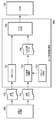
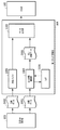
図12は、本実施形態における画像処理部104の構成例を示すブロック図である。画像処理部104は、第一の反転処理部1200、第二の反転処理部1202、および画像合成部1201を有する。画像合成部1201は、入力される2つのフレームデータを画素毎に重ね合わせる合成処理を行う。第二の反転処理部1202は、画像合成部1201の出力データを受け取り、反転処理をしてDRAM102に書き込む。第一の反転処理部1200は、画像合成部1201が既に合成済みのフレームデータを必要とする場合に、該フレームデータをDRAM102から読み出し、反転処理をして画像合成部1201へ転送する。第一および第二の反転処理部1200、1202で行われる処理は、第1実施形態における第一および第二の反転処理部202、204とそれぞれ同様であるため、詳細は省略する。
次に、図13を参照して、4つのフレームを合成する流れを説明する。図13は、異なる4つの露出条件で記録されたフレームデータ(F1300~F1303)と、それらを合成して得られるフレームデータ(F1304~F1306)とを模式的に表した図である。フレームデータF1300~F1303は、画像入力部103がDRAM102に格納するデータである。本実施形態では、異なる3つの条件で合成したフレームデータを、反転した状態で生成することを想定している。すなわち、フレームデータF1300とフレームデータF1301とを合成したフレームデータF1304を、反転した状態で生成することを想定している。また、フレームデータF1300~F1302を合成したフレームデータF1305を、反転した状態で生成することを想定している。また、フレームデータF1300~F1303を合成したフレームデータF1306を、反転した状態で生成することを想定している。
まず、画像合成部1201は、DRAM102からフレームデータF1300とフレームデータF1301とを読み出し、合成処理を行った画素データを、第二の反転処理部1202を介してDRAM102へ格納する。1フレーム分の合成処理を繰り返すことで、反転されたフレームデータF1304をDRAM102上に保持できる。続いて、フレームデータF1305を生成する。フレームデータF1305は、フレームデータF1304とフレームデータF1302との合成で代替することができる。しかしながら、本実施形態において、DRAM102に保存されたフレームデータF1304は、最終的に必要とされる、反転されたフレームデータである。合成処理では反転する前のフレームデータが使用されるので、合成処理を短縮するためには、反転する前のフレームデータF1304もDRAM102上に保持しておくべきである。しかし、反転されたフレームデータと反転する前のフレームデータとの両方をDRAM102に格納することは、メモリ帯域とメモリ使用領域の増加を招いてしまう。そこで、本実施形態では第一の反転処理部1200を設け、DRAM102上にある反転されたフレームデータを合成処理に使用する場合は、第一の反転処理部1200を介し、再度反転してから画像合成部1201へ入力する。こうすることで、メモリ(DRAM102)にフレームデータを書き出す回数を抑えつつ、合成処理を短縮することができる。図13に示すケースでは、フレームデータF1306の生成においても、反転して格納されたフレームデータF1305を、第一の反転処理部1200を介して読み出し、フレームデータF1303をDRAM102から直接読み出す。こうすることで、同様の効果を得ることができる。
以上説明したように本実施形態によれば、異なる条件で生成されたフレームデータを重ね合わせる処理と、反転処理等とを続けて行う場合においても、フレームデータをメモリに書き出す回数を削減し、使用するメモリ帯域とメモリ領域を削減することができる。
[第5実施形態]
これまで、第1~第4実施形態では画像処理部104の各構成各処理をハードウェア実装する場合について述べた。しかしながら画像処理部104は、ハードウェア実装に限定されるものではなく、例えば画像処理部104の一部、あるいは全てを、CPUを用いてソフトウェア実装した場合でも有効である。第5実施形態では、画像処理部104の処理を全てソフトウェア実装した際の動作を説明する。この場合、図1に示す画像処理部104の各構成は、CPU101によって実現される機能構成になる。なお、本実施形態では、画像処理部104で巡回型NR処理と反転処理とを行う場合を例として挙げるが、第1~第4実施形態でこれまで述べてきたように、それに限られるものではない。図14A及び図14Bは全体として、画像処理部104が実行する処理を示すフローチャートである。画像処理部104専用のCPU(不図示)が、図14A及び図14Bに示すフローに沿った処理を実現するプログラムを読み出し、実行させる。また、以下の説明では、画像処理部104の画像処理を行うCPUは、CPU101とは別のCPUを想定しているが、CPU101が行ってもよい。
これまで、第1~第4実施形態では画像処理部104の各構成各処理をハードウェア実装する場合について述べた。しかしながら画像処理部104は、ハードウェア実装に限定されるものではなく、例えば画像処理部104の一部、あるいは全てを、CPUを用いてソフトウェア実装した場合でも有効である。第5実施形態では、画像処理部104の処理を全てソフトウェア実装した際の動作を説明する。この場合、図1に示す画像処理部104の各構成は、CPU101によって実現される機能構成になる。なお、本実施形態では、画像処理部104で巡回型NR処理と反転処理とを行う場合を例として挙げるが、第1~第4実施形態でこれまで述べてきたように、それに限られるものではない。図14A及び図14Bは全体として、画像処理部104が実行する処理を示すフローチャートである。画像処理部104専用のCPU(不図示)が、図14A及び図14Bに示すフローに沿った処理を実現するプログラムを読み出し、実行させる。また、以下の説明では、画像処理部104の画像処理を行うCPUは、CPU101とは別のCPUを想定しているが、CPU101が行ってもよい。
画像処理部104はフレーム単位に、図14A及び図14Bに示すフローに沿って処理を行う。
まず、画像処理部104は、フレーム処理開始と共に、当該フレーム処理に必要な各種設定値をCPU101から受信する(ステップS1400)。ここでいう設定値は、一度に処理する画素数、読み出し側の反転処理のON/OFF、書き込み側の反転処理のON/OFFを含む。次に、画像処理部104は、画像入力部103がメモリに書き出したフレームデータの中から、設定された画素数分の画素データを読み出し(ステップS1401)、読み出した処理フレームの画素データに所定の画像処理を施す(ステップS1402)。これを処理フレームの画素データとする。続いて、画像処理部104は、CPU101から設定された読み出し側の反転処理のON/OFFに従って、参照するフレームの読み出しアドレスの設定を切り換える(ステップS1403)。読み出し側の反転処理がONに設定されている場合、画像処理部104は、メモリに格納された参照フレームの画素データを主走査方向及び副走査方向共に逆から読み出せるように、読み出しアドレスを設定する(ステップS1404)。例えば、画像処理部104は、32Byte分の画素データを一度に扱う場合、フレームデータが格納された最終番地から32Byte分前のアドレスから読み出せるように読み出しアドレスを設定すればよい。一方、読み出し側の反転処理がOFFに設定されている場合、画像処理部104は、処理フレームの読み出し順と同じ順序で画素データをそのまま読み出せるよう読み出しアドレスを設定する(ステップS1405)。画像処理部104は、いずれの場合も設定された読み出しアドレスをもとに、所定の画素数分の参照フレームの画素データを読み出す(ステップS1406)。そして、画像処理部104は、処理フレームの画素データに、対応する参照フレームの画素データを重ね合わせ、巡回型NR処理を行う(ステップS1407)。次に、画像処理部104は、巡回型NR処理後の画素データをメモリに書き出す。ここでも読み出し時と同様に、画像処理部104は、CPUから設定された書き込み側の反転処理のON/OFF設定に従って、書き込みアドレスの設定を切り換える(ステップS1408)。書き込み側の反転処理がONに設定されている場合、画像処理部104は、画素データを反転してメモリに書き込めるように書き込みアドレスを設定する(ステップS1409)。一方、書き込み側の反転処理がOFFに設定されている場合、画像処理部104は、そのままラスタ順でメモリに書き込めるように書き込みアドレスを設定する(ステップS1410)。そして、画像処理部104は、設定した書き込みアドレスをもとにメモリに巡回NR処理後の画素データを書き込む(ステップS1411)。最後に、画像処理部104は、1フレーム分の処理が終わるまで、ステップS1401~ステップS1411まで繰返し行い、1フレーム分の処理が完了したことを確認し、当該フレーム処理の完了とする(ステップS1412)。このような工程で処理をすることによって、画素データを保持するローカルメモリやキャッシュ容量を抑えつつ、ステップS1407で得られる反転処理前のフレームデータをメモリに書き出すことなく巡回型NR処理と反転処理とを続けて行うことができる。
以上説明したように本実施形態によれば、巡回型NR処理と反転処理をソフトウェアによる実装で実施する場合においても、フレームデータをメモリに書き出す回数を削減し、使用するメモリ帯域とメモリ領域を削減することができる。
[その他の実施形態]
本発明は、上述の実施形態の1以上の機能を実現するプログラムを、ネットワーク又は記憶媒体を介してシステム又は装置に供給し、そのシステム又は装置のコンピュータにおける1つ以上のプロセッサーがプログラムを読出し実行する処理でも実現可能である。また、1以上の機能を実現する回路(例えば、ASIC)によっても実現可能である。
本発明は、上述の実施形態の1以上の機能を実現するプログラムを、ネットワーク又は記憶媒体を介してシステム又は装置に供給し、そのシステム又は装置のコンピュータにおける1つ以上のプロセッサーがプログラムを読出し実行する処理でも実現可能である。また、1以上の機能を実現する回路(例えば、ASIC)によっても実現可能である。
本出願は、2016年3月18日に出願された日本国特許出願第2016-055542号に基づいて優先権を主張し、前記日本国特許出願は、この参照によって本明細書に含まれる。
102 DRAM
104 画像処理部
200 入力フレームデータ
201 前段処理部
202 反転処理部
203 巡回型NR処理部
204 反転処理部
205 出力フレームデータ
104 画像処理部
200 入力フレームデータ
201 前段処理部
202 反転処理部
203 巡回型NR処理部
204 反転処理部
205 出力フレームデータ
Claims (17)
- フレーム単位の画像データを格納する領域を有するメモリを備えた画像処理装置であって、
第一の処理対象のフレームの画像データを入力する入力手段と、
前記メモリに格納されている、前記第一の処理対象のフレームに関連するフレームである第一の参照フレームの画像データを反転して出力する第一の反転処理手段と、
前記入力手段で入力された前記第一の処理対象のフレームの画像データに対して、前記第一の反転処理手段によって反転された前記第一の参照フレームの画像データに基づいて画像処理を行なう画像処理手段と、
前記画像処理手段によって画像処理された前記第一の処理対象のフレームの画像データを、第二の処理対象のフレームに関連する第二の参照フレームとして、反転して前記メモリに格納する第二の反転処理手段と
を有することを特徴とする画像処理装置。 - 前記入力手段は、第一の画素順の画像データを入力し、
前記第一の反転処理手段は、前記第一の画素順とは異なる第二の画素順の画像データを、前記第一の画素順の画像データに反転し、
前記第二の反転処理手段は、前記第一の画素順の画像データを、前記第二の画素順の画像データに反転することを特徴とする請求項1に記載の画像処理装置。 - 前記第一の反転処理手段は、前記メモリへの書き込み順の変更および前記メモリへの書き込み先の先頭アドレスの変更の少なくとも一方を実行することで反転処理を行なうことを特徴とする請求項1または2に記載の画像処理装置。
- 前記第二の反転処理手段は、前記メモリからの読み出し順の変更および前記メモリからの読み出し先頭アドレスの変更の少なくとも一方を実行することで反転処理を行なうことを特徴とする請求項1から3のいずれか一項に記載の画像処理装置。
- 前記第一の反転処理手段および前記第二の反転処理手段に対して反転処理を実行するか否かをフレーム単位で切り替える設定をする設定手段をさらに有することを特徴とする請求項1から4のいずれか一項に記載の画像処理装置。
- フレーム単位の画像データを格納する領域を有するメモリを備えた画像処理装置であって、
第一の処理対象のフレームの画像データを入力する入力手段と、
前記メモリに格納されている、前記第一の処理対象のフレームに関連するフレームである第一の参照フレームの画像データを幾何変換して出力する第一の幾何変換処理手段と、
前記入力手段で入力された前記第一の処理対象のフレームの画像データに対して、前記第一の幾何変換処理手段によって幾何変換された前記第一の参照フレームの画像データに基づいて画像処理を行なう画像処理手段と、
前記画像処理手段によって画像処理された前記第一の処理対象のフレームの画像データを、第二の処理対象のフレームに関連する第二の参照フレームとして、幾何変換して前記メモリに格納する第二の幾何変換処理手段と
を有することを特徴とする画像処理装置。 - 前記入力手段は、第一の回転角の画像データを入力し、
前記第一の幾何変換処理手段は、前記第一の回転角とは異なる第二の回転角の画像データを、前記第一の回転角の画像データに幾何変換し、
前記第二の幾何変換処理手段は、前記第一の回転角の画像データを、前記第二の回転角の画像データに幾何変換することを特徴とする請求項6に記載の画像処理装置。 - 前記入力手段は、第一の変倍率の画像データを入力し、
前記第一の幾何変換処理手段は、前記第一の変倍率とは異なる第二の変倍率の画像データを、前記第一の変倍率の画像データに幾何変換し、
前記第二の幾何変換処理手段は、前記第一の変倍率の画像データを、前記第二の変倍率の画像データに幾何変換することを特徴とする請求項6に記載の画像処理装置。 - 前記第一の幾何変換処理手段は、前記メモリに格納されている前記画像データの画素の読み出し座標を示す読み出し座標データを幾何変換し、前記読み出し座標データに対応する画素を出力することで前記幾何変換を行い、
前記第二の幾何変換処理手段は、前記画像データの画素の出力座標を示す出力座標データを幾何変換し、前記出力座標データに対応する画素を前記メモリの対応する領域に格納することで前記幾何変換を行なうことを特徴とする請求項6に記載の画像処理装置。 - 前記第一の幾何変換処理手段は、設定されたパラメータに従って前記読み出し座標データを幾何変換し、
前記第二の幾何変換処理手段は、設定されたパラメータに従って前記出力座標データを幾何変換することを特徴とする請求項9に記載の画像処理装置。 - 前記第一の幾何変換処理手段は、LUTを参照して前記読み出し座標データを幾何変換し、
前記第二の幾何変換処理手段は、LUTを参照して前記出力座標データを幾何変換することを特徴とする請求項9に記載の画像処理装置。 - 前記第一の幾何変換処理手段および前記第二の幾何変換処理手段に対して前記幾何変換を実行するか否かをフレーム単位で切り替える設定をする設定手段をさらに有することを特徴とする請求項6から11のいずれか一項に記載の画像処理装置。
- 前記第一の参照フレームの画像データは、前記第一の処理対象のフレームよりも前のフレームの画像データであり、前記画像処理は巡回型ノイズ低減処理であることを特徴とする請求項1から12のいずれか一項に記載の画像処理装置。
- 前記第一の参照フレームの画像データは、前記第一の処理対象のフレームとは異なる露出条件で同じタイミングで撮像された画像データ、または、異なる露出条件で撮像された画像データを合成した画像データであり、前記画像処理はHDR処理であることを特徴とする請求項1から12のいずれか一項に記載の画像処理装置。
- フレーム単位の画像データを格納する領域を有するメモリを備えた画像処理装置における制御方法であって、
第一の処理対象のフレームの画像データを入力する入力ステップと、
前記メモリに格納されている、前記第一の処理対象のフレームに関連するフレームである第一の参照フレームの画像データを反転して出力する第一の反転処理ステップと、
前記入力ステップで入力された前記第一の処理対象のフレームの画像データに対して、前記第一の反転処理ステップによって反転された前記第一の参照フレームの画像データに基づいて画像処理を行なう画像処理ステップと、
前記画像処理ステップにおいて画像処理された前記第一の処理対象のフレームの画像データを、第二の処理対象のフレームに関連する第二の参照フレームとして、反転して前記メモリに格納する第二の反転処理ステップと
を有することを特徴とする制御方法。 - フレーム単位の画像データを格納する領域を有するメモリを備えた画像処理装置における制御方法であって、
第一の処理対象のフレームの画像データを入力する入力ステップと、
前記メモリに格納されている、前記第一の処理対象のフレームに関連するフレームである第一の参照フレームの画像データを幾何変換して出力する第一の幾何変換処理ステップと、
前記入力ステップで入力された前記第一の処理対象のフレームの画像データに対して、前記第一の幾何変換処理ステップにおいて幾何変換された前記第一の参照フレームの画像データに基づいて画像処理を行なう画像処理ステップと、
前記画像処理ステップにおいて画像処理された前記第一の処理対象のフレームの画像データを、第二の処理対象のフレームに関連する第二の参照フレームとして、幾何変換して前記メモリに格納する第二の幾何変換処理ステップと
を有することを特徴とする制御方法。 - コンピュータを、請求項1から14のいずれか一項に記載の画像処理装置の各手段として機能させるためのプログラム。
Priority Applications (1)
| Application Number | Priority Date | Filing Date | Title |
|---|---|---|---|
| US16/127,367 US10713757B2 (en) | 2016-03-18 | 2018-09-11 | Image processing apparatus, control method thereof, and storage medium |
Applications Claiming Priority (2)
| Application Number | Priority Date | Filing Date | Title |
|---|---|---|---|
| JP2016055542A JP6750847B2 (ja) | 2016-03-18 | 2016-03-18 | 画像処理装置およびその制御方法並びにプログラム |
| JP2016-055542 | 2016-03-18 |
Related Child Applications (1)
| Application Number | Title | Priority Date | Filing Date |
|---|---|---|---|
| US16/127,367 Continuation US10713757B2 (en) | 2016-03-18 | 2018-09-11 | Image processing apparatus, control method thereof, and storage medium |
Publications (1)
| Publication Number | Publication Date |
|---|---|
| WO2017159137A1 true WO2017159137A1 (ja) | 2017-09-21 |
Family
ID=59852249
Family Applications (1)
| Application Number | Title | Priority Date | Filing Date |
|---|---|---|---|
| PCT/JP2017/004725 Ceased WO2017159137A1 (ja) | 2016-03-18 | 2017-02-09 | 画像処理装置およびその制御方法並びにプログラム |
Country Status (3)
| Country | Link |
|---|---|
| US (1) | US10713757B2 (ja) |
| JP (1) | JP6750847B2 (ja) |
| WO (1) | WO2017159137A1 (ja) |
Families Citing this family (3)
| Publication number | Priority date | Publication date | Assignee | Title |
|---|---|---|---|---|
| JP6886622B2 (ja) * | 2018-01-22 | 2021-06-16 | 京セラドキュメントソリューションズ株式会社 | 画像処理装置 |
| JP7000383B2 (ja) | 2019-07-04 | 2022-01-19 | 株式会社デンソー | 画像処理装置および画像処理方法 |
| CN110958363B (zh) * | 2019-12-04 | 2022-04-15 | RealMe重庆移动通信有限公司 | 图像处理方法及装置、计算机可读介质和电子设备 |
Citations (3)
| Publication number | Priority date | Publication date | Assignee | Title |
|---|---|---|---|---|
| JPH06237396A (ja) * | 1993-02-10 | 1994-08-23 | Mitsubishi Electric Corp | 映像信号処理回路 |
| JP2002300428A (ja) * | 2001-03-30 | 2002-10-11 | Sony Corp | 画像ノイズ低減装置及び画像ノイズ低減方法 |
| JP2005278073A (ja) * | 2004-03-26 | 2005-10-06 | Hitachi Ltd | 撮像装置 |
Family Cites Families (4)
| Publication number | Priority date | Publication date | Assignee | Title |
|---|---|---|---|---|
| JP4178481B2 (ja) | 2006-06-21 | 2008-11-12 | ソニー株式会社 | 画像処理装置、画像処理方法、撮像装置および撮像方法 |
| JP5284446B2 (ja) * | 2011-11-14 | 2013-09-11 | 株式会社東芝 | 画像処理装置、及び画像処理方法 |
| US9813620B2 (en) * | 2014-03-31 | 2017-11-07 | JVC Kenwood Corporation | Image processing apparatus, image processing method, program, and camera |
| JP5893712B1 (ja) * | 2014-11-04 | 2016-03-23 | オリンパス株式会社 | 撮像装置、撮像方法、処理プログラム |
-
2016
- 2016-03-18 JP JP2016055542A patent/JP6750847B2/ja active Active
-
2017
- 2017-02-09 WO PCT/JP2017/004725 patent/WO2017159137A1/ja not_active Ceased
-
2018
- 2018-09-11 US US16/127,367 patent/US10713757B2/en active Active
Patent Citations (3)
| Publication number | Priority date | Publication date | Assignee | Title |
|---|---|---|---|---|
| JPH06237396A (ja) * | 1993-02-10 | 1994-08-23 | Mitsubishi Electric Corp | 映像信号処理回路 |
| JP2002300428A (ja) * | 2001-03-30 | 2002-10-11 | Sony Corp | 画像ノイズ低減装置及び画像ノイズ低減方法 |
| JP2005278073A (ja) * | 2004-03-26 | 2005-10-06 | Hitachi Ltd | 撮像装置 |
Also Published As
| Publication number | Publication date |
|---|---|
| US20190005622A1 (en) | 2019-01-03 |
| US10713757B2 (en) | 2020-07-14 |
| JP6750847B2 (ja) | 2020-09-02 |
| JP2017175181A (ja) | 2017-09-28 |
Similar Documents
| Publication | Publication Date | Title |
|---|---|---|
| JP7164706B2 (ja) | 画像繋ぎ合わせ方法及び装置、車載画像処理装置、電子機器、記憶媒体 | |
| KR102910920B1 (ko) | 데이터 처리 시스템 | |
| TWI524306B (zh) | 圖像轉換和多視圖輸出系統及方法 | |
| US20150254820A1 (en) | Semiconductor integrated circuit and multi-angle video system | |
| JP5925579B2 (ja) | 半導体装置、電子装置、及び画像処理方法 | |
| JP4991907B2 (ja) | 画像処理装置、および、画像処理装置の制御方法 | |
| US9462189B2 (en) | Piecewise perspective transform engine | |
| JP2015053644A (ja) | 撮像装置 | |
| JP6750847B2 (ja) | 画像処理装置およびその制御方法並びにプログラム | |
| JP5318225B2 (ja) | 画像合成装置及び画像合成プログラム | |
| JP2012023666A (ja) | 画像変換装置及び画像変換システム | |
| JP2017017672A (ja) | 画像処理装置、画像処理方法および画像処理プログラム | |
| JP6295619B2 (ja) | 画像処理装置及び方法、並びに電子機器 | |
| WO2015098721A1 (ja) | 画像処理装置、画像処理方法、画像処理用プログラム、および、撮像装置 | |
| JP2013025619A (ja) | 画像表示装置および画像表示方法 | |
| JP5959684B2 (ja) | 画像変換システム | |
| JP6273881B2 (ja) | 画像処理装置、画像処理方法、及びプログラム | |
| JP6440465B2 (ja) | 画像処理装置、画像処理方法及びプログラム | |
| TWI424371B (zh) | Video processing device and processing method thereof | |
| JP2000059800A (ja) | 画像信号処理回路 | |
| JP6828604B2 (ja) | 画像処理装置、画像処理方法およびプログラム | |
| JP5890044B2 (ja) | 車両 | |
| JPH05292393A (ja) | 動画編集処理方式 | |
| JP2013183383A (ja) | 撮像装置、撮像方法、及びプログラム | |
| JP2014127757A (ja) | 撮像装置 |
Legal Events
| Date | Code | Title | Description |
|---|---|---|---|
| NENP | Non-entry into the national phase |
Ref country code: DE |
|
| 121 | Ep: the epo has been informed by wipo that ep was designated in this application |
Ref document number: 17766145 Country of ref document: EP Kind code of ref document: A1 |
|
| 122 | Ep: pct application non-entry in european phase |
Ref document number: 17766145 Country of ref document: EP Kind code of ref document: A1 |