WO2017159099A1 - 排ガス処理装置 - Google Patents
排ガス処理装置 Download PDFInfo
- Publication number
- WO2017159099A1 WO2017159099A1 PCT/JP2017/003677 JP2017003677W WO2017159099A1 WO 2017159099 A1 WO2017159099 A1 WO 2017159099A1 JP 2017003677 W JP2017003677 W JP 2017003677W WO 2017159099 A1 WO2017159099 A1 WO 2017159099A1
- Authority
- WO
- WIPO (PCT)
- Prior art keywords
- exhaust gas
- liquid return
- flue
- reducer
- return ring
- Prior art date
- Legal status (The legal status is an assumption and is not a legal conclusion. Google has not performed a legal analysis and makes no representation as to the accuracy of the status listed.)
- Ceased
Links
Images






Classifications
-
- B—PERFORMING OPERATIONS; TRANSPORTING
- B01—PHYSICAL OR CHEMICAL PROCESSES OR APPARATUS IN GENERAL
- B01D—SEPARATION
- B01D53/00—Separation of gases or vapours; Recovering vapours of volatile solvents from gases; Chemical or biological purification of waste gases, e.g. engine exhaust gases, smoke, fumes, flue gases, aerosols
- B01D53/14—Separation of gases or vapours; Recovering vapours of volatile solvents from gases; Chemical or biological purification of waste gases, e.g. engine exhaust gases, smoke, fumes, flue gases, aerosols by absorption
- B01D53/18—Absorbing units; Liquid distributors therefor
-
- B—PERFORMING OPERATIONS; TRANSPORTING
- B01—PHYSICAL OR CHEMICAL PROCESSES OR APPARATUS IN GENERAL
- B01D—SEPARATION
- B01D53/00—Separation of gases or vapours; Recovering vapours of volatile solvents from gases; Chemical or biological purification of waste gases, e.g. engine exhaust gases, smoke, fumes, flue gases, aerosols
- B01D53/34—Chemical or biological purification of waste gases
- B01D53/46—Removing components of defined structure
- B01D53/48—Sulfur compounds
- B01D53/50—Sulfur oxides
-
- B—PERFORMING OPERATIONS; TRANSPORTING
- B01—PHYSICAL OR CHEMICAL PROCESSES OR APPARATUS IN GENERAL
- B01D—SEPARATION
- B01D53/00—Separation of gases or vapours; Recovering vapours of volatile solvents from gases; Chemical or biological purification of waste gases, e.g. engine exhaust gases, smoke, fumes, flue gases, aerosols
- B01D53/34—Chemical or biological purification of waste gases
- B01D53/74—General processes for purification of waste gases; Apparatus or devices specially adapted therefor
- B01D53/77—Liquid phase processes
- B01D53/78—Liquid phase processes with gas-liquid contact
Definitions
- the present invention relates to an exhaust gas treatment apparatus.
- the upper liquid return structure may have at least one of a flue protrusion and an upper liquid return ring.
- the flue protrusion may be a portion provided by extending a part of the flue to the reducer.
- the upper liquid return ring may protrude from the inner wall of the reducer part.
- the upper liquid return ring may be provided in a ring shape on the inner wall of the reducer part.
- the inner diameters of the flue protrusion, upper liquid return ring, and lower liquid return ring may be smaller in the order of the flue protrusion, upper liquid return ring, and lower liquid return ring.
- the upper liquid return ring may have a flange part and a cylindrical part.
- the flange portion may contact the inner wall of the reducer portion.
- the cylindrical portion may be provided in contact with the inner diameter of the flange portion.
- the cylindrical portion of the upper liquid return ring may have a truncated cone shape.
- the frustoconical shape may have an inner surface parallel to the inner wall of the reducer portion.
- the cylindrical part of the upper liquid return ring may be cylindrical.
- the cylindrical shape may have an inner surface parallel to the inner wall of the reaction tower.
- the flange portion of the upper liquid return ring may be provided orthogonal to the inner wall of the reducer portion.
- At least a part of the flue protrusion may have a cylindrical portion.
- the cylindrical portion may have a truncated cone shape whose inner diameter increases toward the bottom side.
- the exhaust gas treatment apparatus may further include a trunk pipe, a plurality of branch pipes, and a plurality of injection units.
- the trunk tube may carry liquid.
- the main pipe may extend in the height direction in the internal space of the reaction tower.
- the plurality of branch pipes may be provided at different height positions.
- the plurality of branch pipes may be provided extending from the outer wall of the trunk pipe toward the inner wall of the reaction tower.
- the plurality of ejection units may eject the liquid supplied from the trunk tube.
- the plurality of injection units may be provided in each of the plurality of branch pipes. In the branch pipe located on the uppermost side among the plurality of branch pipes, the main direction defined by the center of the spray angle in the plurality of jetting units that jet the liquid may be inclined toward the bottom side.
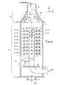
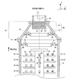
- FIG. 1 is a diagram showing an outline of an exhaust gas treatment apparatus 100 in the first embodiment.
- FIG. 1 is a front view of the exhaust gas treatment apparatus 100.
- FIG. 1 shows a cross section of the exhaust gas treatment apparatus 100.
- the trunk tube 20, the branch tube 22, the injection unit 24, the liquid introduction unit 28, and the baffle 29 show side surfaces instead of cross sections.
- the exhaust gas introduction part 16 provided before the paper surface of the reaction tower 10 is shown with a dotted line.
- the longitudinal direction of the reaction tower 10 is the z direction.
- the z direction is equal to the height direction from the bottom 14 side to the top 12 side of the reaction tower 10.
- the x and y directions are perpendicular to each other.
- the x, y and z directions constitute a right-handed system.
- the z direction is a direction perpendicular to a plane having x and y directions.
- the z direction may be a direction perpendicular to the floor of the ship or a direction perpendicular to the ground.
- the z direction is not limited to the examples of these directions.
- the z direction may be a direction parallel to the ground.
- the + z direction may be referred to as “upper”, “upward”, or “upper”, and the ⁇ z direction may be referred to as “lower”, “lower”, “lower”, or “bottom”.
- the exhaust gas treatment apparatus 100 includes a reaction tower 10, a reducer unit 30, a flue unit 40, and an upper liquid return structure 60.
- the upper liquid return structure 60 includes a flue protrusion 42 or an upper liquid return ring 50 described later.
- the upper liquid return structure 60 of this example is a flue protrusion 42.
- the reaction tower 10 and the flue section 40 of this example have a cylindrical internal space 15 extending in the height direction.
- the reducer part 30 of this example has the internal space 15 of truncated cone shape.
- the internal space 15 in the reaction tower 10, the reducer part 30 and the flue part 40 of this example has a common central axis 11.
- the central axis 11 in this example is parallel to the z direction.
- the central axis 11 in this example is also the central axis of the trunk tube 20.
- the distance from the central axis 11 to the inner wall of the reaction tower 10 is constant.
- the distance from the central axis 11 to the inner walls of the flue 40 and the flue protrusion 42 is constant.
- the distance from the central axis 11 to the inner wall of the reducer unit 30 is constant. Note that the distance from the central axis 11 to the inner wall of the reducer portion 30 gradually decreases as the direction proceeds in the + z direction.
- the reaction tower 10 has an exhaust gas introduction part 16 on the side surface on the bottom part 14 side.
- the exhaust gas introduction part 16 may be a conduit having a rectangular cross section when the reaction tower 10 is viewed from the front.
- the exhaust gas introduction part 16 may have a longitudinal part extending in a direction perpendicular to a rectangular cross section. In this example, the longitudinal part of the exhaust gas introduction part 16 is parallel to the x direction.
- the longitudinal part of the exhaust gas introduction part 16 of this example has an inner side wall 17 and an outer side wall 18.
- the outer side wall 18 of the exhaust gas introduction part 16 extends in the tangential direction of the outer diameter of the reaction tower 10.
- the inner side wall 17 of the exhaust gas introduction part 16 extends in a direction intersecting with the side wall of the reaction tower 10.
- the exhaust gas is introduced into the reaction tower 10 from the exhaust gas introduction part 16 located on the bottom 14 side.
- the exhaust gas may be exhaust gas discharged from a power device such as a ship engine.
- the exhaust gas is introduced into the reaction tower 10 from the exhaust gas introduction unit 16 so as to swirl in a predetermined swirling direction inside the reaction tower 10.
- the exhaust gas of this example rises while spirally turning in the internal space 15 of the reaction tower 10. By exhausting the liquid inside the reaction tower 10, the exhaust gas is washed. Thereafter, the exhaust gas is discharged from the flue portion 40 to the outside of the exhaust gas processing apparatus 100.
- the reducer unit 30 is provided above the reaction tower 10.
- the reducer part 30 may be a joint part that connects two cylinders having different diameters.
- the reducer portion 30 has a small diameter portion 32 at an end portion in the height direction, and has a large diameter portion 34 at an end portion in the direction opposite to the height direction.
- the small diameter part 32 of the reducer part 30 is connected to the flue part 40, and the large diameter part 34 of the reducer part 30 is connected to the reaction tower 10. That is, the reducer section 30 of this example connects the reaction tower 10 and the flue section 40 having an inner diameter smaller than that of the reaction tower 10.
- the inner diameter can be gradually reduced from the upper part 12 of the reaction tower 10 to the flue section 40. Therefore, the pressure loss in the exhaust gas treatment device 100 can be reduced by directly connecting the reaction tower 10 and the flue section 40 as compared with the case where the inner diameter of the cylinder changes discontinuously in the height direction.
- a part of the flue section 40 is provided extending to the reducer section 30. That is, a part of the flue portion 40 extending in the ⁇ z direction from the top of the reducer portion 30 is referred to as a flue protrusion 42.
- the remaining part of the flue section 40 is provided above the reducer section 30.
- the flue protrusion part 42 and the reducer part 30 may be fixed.
- the outer diameter of the flue protrusion 42 and the inner diameter of the small diameter portion 32 of the reducer portion 30 coincide.
- the reaction tower 10 is not provided with a liquid return structure, but the reducer section 30 is provided with a liquid return structure.
- the upper liquid return structure 60 of this example is a flue protrusion 42 provided in the reducer part 30.
- the exhaust gas treatment apparatus 100 of this example is particularly suitable for a ship or the like that has no sufficient installation space.
- the mist-like liquid may be easily discharged from the flue portion 40 to the outside.
- the exhaust gas treatment apparatus 100 of this example since the upper liquid return structure 60 is provided, the mist-like liquid discharged outside from the flue portion 40 can be reduced.
- the reaction tower 10 of this example has a length in the height direction from the bottom 14 to the top 12 of 3 [m] and an inner diameter of 700 [mm].
- the reducer portion 30 of this example has a length in the height direction from the large diameter portion 34 to the small diameter portion 32 of 654 [mm].
- the inner diameter of the small diameter portion 32 of the reducer portion 30 may be about 60% of the large diameter portion 34.
- the inner diameter of the small diameter portion 32 of the reducer portion 30 of this example is 420 [mm].
- the length from the uppermost part (position of the small diameter part 32) of the reducer part 30 to the lower end of the flue protrusion 42 is referred to as the protrusion length of the flue protrusion 42.
- the exhaust gas treatment apparatus 100 includes a drainage outlet 19, a trunk pipe 20, a branch pipe 22, an injection part 24, a liquid introduction part 28, and a baffle 29.
- the bottom part 14 of the reaction tower 10 may function as a drainage storage part that temporarily stores the liquid that has been dropped after being jetted inside the reaction tower 10. The liquid stored in the bottom 14 may finally be discharged out of the reaction tower 10 from the drainage outlet 19.
- the liquid introduction part 28 of this example is introduced into the inside from the side surface of the reaction tower 10 in the vicinity of the bottom 14 of the reaction tower 10.
- the liquid introducing portion 28 in this example is a tube bent into an L shape.
- the liquid introduction part 28 of this example is watertightly connected to the trunk pipe 20 in parallel with the central axis 11. Seawater, lake water, river water, or alkaline liquid is introduced into the liquid introduction unit 28 from the outside of the reaction tower 10 using a pump or the like.
- the liquid introduction unit 28 and the trunk tube 20 are fluidly connected, and the liquid introduced into the liquid introduction unit 28 is supplied to the trunk tube 20.
- the plurality of branch pipes 22 are provided extending from the outer wall of the trunk pipe 20 toward the inner wall of the reaction tower 10. In this example, one end in the longitudinal direction of the branch pipe 22 may be welded to the trunk pipe 20. In this example, four branch pipes 22-A, 22-B, 22-C and 22-D are provided at the same height position. The four branch pipes 22-A to 22-D form a cross when the trunk pipe 20 is viewed from above. Note that the branch pipe 22-D is omitted in FIG.
- the branch pipes 22-1A to 22-nA in this example are provided so as to overlap in the height direction.
- the branch pipes 22-1A to 22-nA of the present example are provided at different height positions spaced apart at a constant interval in the height direction.
- n is a natural number of 2 or more.
- n 8.
- the pitch in the height direction of the branch pipes 22 may be 0.3 [m].
- the branch pipes 22-1B to 22-nB are also provided at different height positions by a predetermined pitch. The same applies to the branch pipe 22-1C to the branch pipe 22-nC and the branch pipe 22-1D to the branch pipe 22-nD.
- a plurality of injection units 24 are provided in each of the plurality of branch pipes 22.
- two jet parts 24 are provided in one branch pipe 22.
- the number of the injection parts 24 provided in one branch pipe 22 is not limited to two, and may be three or more.
- the injection unit 24 may be connected to the branch pipe 22 by screwing means, or may be connected to the branch pipe 22 by welding.
- the injection unit 24 injects the liquid supplied from the trunk tube 20 inside the reaction tower 10.
- the ejected liquid changes into a fine water droplet or a mist.
- sulfur oxides and the like in the exhaust gas are absorbed by the liquid.
- exhaust gas can be washed.
- the ejection unit 24 may be a spray nozzle that ejects liquid in an empty cone shape.
- the injection port of the injection part 24 is provided in the part which attached
- the injection unit 24 may inject the liquid so as to assist the swirling flow of the exhaust gas.
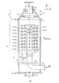
- FIG. 2 is a diagram showing an outline of the exhaust gas treatment device 110 in the second embodiment.
- the exhaust gas treatment device 110 of this example does not have the flue protrusion 42.
- the bottom part of the flue part 40 of this example is fixed on the small diameter part 32 of the reducer part 30.
- the inner diameter of the flue portion 40 and the inner diameter of the small diameter portion 32 of the reducer portion 30 coincide.
- the upper liquid return structure 60 in this example is an upper liquid return ring 50. This is different from the first embodiment. Other points are the same as in the first embodiment.
- the upper liquid return ring 50 has a flange portion 52 and a cylindrical portion 54.
- the upper liquid return ring 50 protrudes from the inner wall of the reducer part 30.
- the upper liquid return ring 50 is provided in a ring shape on the inner wall of the reducer portion 30.
- a circumferential portion of the outer diameter of the flange portion 52 is fixed in contact with the inner wall of the reducer portion 30.
- the flange portion 52 may be passed through the reducer portion 30. That is, the outer diameter of the flange portion 52 may protrude from the outer wall of the reducer portion 30.
- the protruding portion may be fixed to the reducer portion 30 by a fixing member.
- the cylindrical portion 54 is provided in contact with the inner diameter of the flange portion 52.
- the cylindrical portion 54 of this example is provided closer to the central axis 11 than the inner diameter of the flange portion 52.
- the shape of the cylindrical portion 54 may be a cylindrical tube or a truncated cone tube.
- the cylindrical part 54 of this example is a cylindrical cylinder.
- the upper liquid return ring 50 of this example has a function of preventing the mist-like liquid from being discharged from the flue portion 40 to the outside.
- the upper liquid return ring 50 prevents the mist-like liquid from rising near the inner surface of the reducer unit 30.
- the upper liquid return ring 50 of this example has an opening 56 in the flange portion 52.
- the opening 56 is provided through the flange portion 52. By providing the opening 56, the liquid staying in the flange portion 52 can fall downward due to its own weight. The dropped liquid is finally discharged out of the exhaust gas treatment device 110 from the drainage outlet 19.
- the liquid return structure is provided in the reducer section 30 but is not provided in the reaction tower 10.
- the upper liquid return structure 60 of this example is an upper liquid return ring 50 provided in the reducer unit 30.
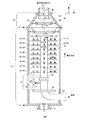
- FIG. 3 is a diagram showing an outline of the exhaust gas treatment device 120 in the third embodiment.
- the upper liquid return structure 60 of this example includes both the flue protrusion 42 of the first embodiment and the upper liquid return ring 50 of the second embodiment. In this respect, this example is different from the first and second embodiments. Since this example has both the flue protrusion 42 and the upper liquid return ring 50, the liquid discharged outside from the flue 40 can be further reduced than in the first and second embodiments. In addition, as in the first and second embodiments, the length in the height direction of the reaction tower 10 can be reduced while providing a liquid return structure.
- FIG. 4 is a diagram showing an outline of the exhaust gas treatment device 130 in the fourth embodiment.
- the exhaust gas treatment device 130 of this example includes a flue protrusion 42 as the upper liquid return structure 60 and a lower liquid return ring 70.
- the exhaust gas treatment device 130 of this example is different from the first embodiment in that it includes a lower liquid return ring 70.
- the lower liquid return ring 70 has the same function as the upper liquid return ring 50.
- the lower liquid return ring 70 may have the same configuration as the upper liquid return ring 50.
- the lower liquid return ring 70 has a flange portion 72 and a cylindrical portion 74.
- the flange portion 72 has an opening 76.
- the opening 76 is provided through the flange portion 72.
- the lower liquid return ring 70 is provided in a ring shape on the inner wall of the reaction tower 10 and protrudes from the inner wall of the reaction tower 10.
- the flange portion 72 is in contact with the inner wall of the reaction tower 10.
- the outer diameter of the flange portion 72 of this example is fixed to the inner wall of the reaction tower 10.
- the cylindrical portion 74 is provided in contact with the position of the inner diameter of the flange portion 72.
- the cylindrical portion 74 of this example is connected to the flange portion 72 and is provided closer to the central axis 11 than the flange portion 72.
- FIG. 5 is a diagram showing an outline of the exhaust gas treatment apparatus 140 in the fifth embodiment.
- the exhaust gas treatment device 130 of this example includes an upper liquid return ring 50 as an upper liquid return structure 60 and a lower liquid return ring 70.
- the exhaust gas treatment device 130 of this example is different from the second embodiment in that it includes a lower liquid return ring 70.
- the upper liquid return ring 50 is the same as that of the second embodiment
- the lower liquid return ring 70 is the same as that of the fourth embodiment.
- the reaction tower 10 is provided with one lower liquid return ring 70. Therefore, the height in the height direction of the reaction column 10 can be reduced as compared with the case where a plurality of lower liquid return rings 70 are provided in the reaction column 10. Furthermore, in this example, since the reaction tower 10 has one lower liquid return ring 70 and the reducer section 30 has one upper liquid return ring 50, the liquid discharged from the flue section 40 can be discharged outside. This can be further reduced than in the second embodiment.
- FIG. 6 is a diagram showing an outline of the exhaust gas treatment apparatus 150 in the sixth embodiment.
- the upper liquid return structure 60 of this example has both the flue protrusion 42 and the upper liquid return ring 50.
- the exhaust gas treatment apparatus 150 of this example includes a lower liquid return ring 70 in the reaction tower 10. This is different from the first to fifth embodiments.
- the length in the height direction of the reaction tower 10 can be reduced as compared with the case where a plurality of lower liquid return rings 70 are provided in the reaction tower 10. Furthermore, the liquid discharged
- the inner diameter of the flue protrusion 42 is R1
- the inner diameter of the upper liquid return ring 50 is R2
- the inner diameter of the lower liquid return ring 70 is R3.
- the inner diameter is made smaller toward the upper part of the exhaust gas treatment device 150. That is, in this example, R1, R2, and R3 are smaller in this order.
- R1, R2 and R3 satisfy the relationship of R1 ⁇ R2 ⁇ R3. Thereby, compared with the case where it is R2 ⁇ R1, R3 ⁇ R2, or R3 ⁇ R1, the pressure loss of the waste gas in the reaction tower 10 can be reduced.
- the relationship of R1 ⁇ R2 ⁇ R3 may be applied in the third to fifth embodiments (FIGS. 3 to 5).
- FIG. 7A is a view showing a cross section of the upper liquid return ring 50.
- FIG. 7B is a view showing the upper surface of the upper liquid return ring 50.
- the configuration of the upper liquid return ring 50 in the yz section (FIG. 7A) has already been described, and thus the description thereof is omitted.
- the flange portion 52 is provided with a plurality of openings 56. Each center of the plurality of openings 56 may be provided on a circumference having a predetermined diameter. The predetermined diameter may be larger than the inner diameter of the flange portion 52 and smaller than the outer diameter of the flange portion 52.
- the centers of the plurality of openings 56 may be closer to the inner diameter than the outer diameter of the flange portion 52.
- the predetermined diameter at which the centers of the plurality of openings 56 are provided is larger than the inner diameter of the flange portion 52 and not more than half of the sum of the inner diameter and the outer diameter of the flange portion 52.
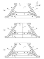
- FIG. 8A to FIG. 8C are cross-sectional views showing modifications of the upper liquid return ring 50.
- FIG. The cylindrical portion 54 in FIGS. 8A and 8B has a truncated cone shape having an inner side surface 55 parallel to the inner wall of the reducer portion 30. Thereby, the pressure loss from the large diameter part 34 of the reducer part 30 to the small diameter part 32 can be reduced.
- the cylindrical portion 54 in FIG. 8C has a cylindrical shape having an inner side surface 55 parallel to the inner wall of the reaction tower 10.
- the flange portion 52 is provided orthogonal to the inner wall of the reducer portion 30. Thereby, the internal diameter of the flange part 52 is located below the outer diameter.
- a groove portion formed by the upper portion of the flange portion 52 and the outer surface 57 of the cylindrical portion 54 is a right angle in FIG. 8A and an acute angle in FIG. 8C.
- the right-angle and acute-angle groove portions can easily store liquid as compared with the example of the obtuse-angle groove portion in FIG. Therefore, the liquid falls easily due to its own weight.
- the upper liquid return ring 50 in FIG. 8B may have a portion that protrudes further outward from the outer diameter of the flange portion 52.
- the protruding portion may be inserted into the reducer portion 30 and pulled out to the outside of the reducer portion 30 and the drawn portion may be screwed. Thereby, installation of the upper liquid return ring 50 is completed. Therefore, the upper liquid return ring 50 of FIG. 8B is easier to install on the reducer unit 30 than the examples of FIGS. 8A and 8C.
- the angle ⁇ formed by the bottom portion of the flange portion 52 and the outer surface 57 of the cylindrical portion 54 is larger than the example of FIGS. 8A and 8B. Therefore, in the example of FIG. 8C, the liquid that rises in the vicinity of the inner wall of the reducer portion 30 and reaches the upper liquid return ring 50 is most easily collected.
- FIG. 9A to FIG. 9C are cross-sectional views showing other modified examples of the upper liquid return ring 50.
- 9A to 9C form an acute angle with the inner wall of the reducer portion 30.
- FIG. Accordingly, the inner diameter of the flange portion 52 is located above the outer diameter of the flange portion 52.
- the groove portion formed by the upper portion of the flange portion 52 and the outer surface 57 of the cylindrical portion 54 has an obtuse angle.
- the cylindrical part 54 may be parallel to the reducer part 30.
- the inner surface 55 and the outer surface 57 of the cylindrical portion 54 are parallel to the inner wall of the reducer portion 30.
- the groove portion formed by the upper portion of the flange portion 52 and the outer surface 57 of the cylindrical portion 54 is a right angle.
- the flange part 52 and the cylindrical part 54 are orthogonally crossed.
- the liquid accumulates in a groove portion formed by the inner wall of the reducer portion 30 and the upper portion of the flange portion 52.
- the accumulated liquid flows out from the opening 56 and sequentially travels along the lower surface of the flange portion 52, the inner wall of the reducer portion 30, and the inner wall of the reaction tower 10.
- the liquid accumulated in the upper liquid return ring 50 can be discharged.
- each opening 46 in the side wall 47 of the flue protrusion 42 is S1.
- the area of each opening 56 of the upper liquid return ring 50 is S2.
- S2 is the area of one opening 56 when the flange portion 52 is viewed from above.
- the area of each opening 76 of the lower liquid return ring 70 is S3.
- S3 is the area of one opening 76 when the flange portion 72 is viewed from above.
- S1 is smaller than S2 and S3.
- the particle size of the liquid tends to decrease as it goes upward in the height direction. Therefore, compared with the case where S1 is made larger than S2 and S3, the liquid collection performance can be improved.
- the size of the opening area may satisfy the relationship of S1 ⁇ S2 ⁇ S3.
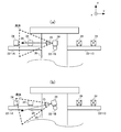
- FIG. 12 (a) and 12 (b) are diagrams for explaining the main direction 26 in the injection section 24 of the branch pipe 22 located on the uppermost side 12 side.
- the main direction 26 of the liquid ejected from the ejection unit 24 is defined by the center of the ejection angle 25 in the ejection unit 24.
- the ejection angle 25 is generally known as an angle at which the liquid spreads in the vicinity of the ejection unit 24 such as a spray nozzle.
- FIG. 12A shows an example in which the main direction 26 of the uppermost injection unit 24 is parallel to the xy plane.
- FIG. 12B is an example in which the main direction 26 of the uppermost injection unit 24 is inclined to the bottom 14 side with respect to the example of FIG. In the example of FIG.
Landscapes
- Engineering & Computer Science (AREA)
- Chemical & Material Sciences (AREA)
- Environmental & Geological Engineering (AREA)
- Analytical Chemistry (AREA)
- General Chemical & Material Sciences (AREA)
- Oil, Petroleum & Natural Gas (AREA)
- Chemical Kinetics & Catalysis (AREA)
- Health & Medical Sciences (AREA)
- Biomedical Technology (AREA)
- Treating Waste Gases (AREA)
- Gas Separation By Absorption (AREA)
Abstract
硫黄酸化物等を吸収した霧状の海水が反応塔から外部へ排出されることを防ぐべく、反応塔の内部においてリング状である複数の液返し構造を設ける場合がある。ただし、複数の液返し構造を設けることにより反応塔の高さ方向長さが増加するので、制限された空間である船舶の室内に反応塔を設けることが困難となる。排ガスを処理する排ガス処理装置であって、排ガスが導入される底部側から排ガスが排出される上部側への高さ方向に延伸する筒形状の内部空間を有し、旋回しながら上昇する排ガスに液体を噴射して洗浄する反応塔と、反応塔よりも上に設けられ、反応塔に接続したレデューサ部と、少なくとも一部がレデューサ部よりも上に設けられた煙道部と、レデューサ部に設けられた上部液返し構造とを備える、排ガス処理装置を提供する。
Description
本発明は、排ガス処理装置に関する。
従来、反応塔内部に導入した排ガスと、反応塔内部に設けられたノズルから噴射される液体とを気液接触させることにより、排ガス中の硫黄酸化物(SOx)等を除去していた。
[先行技術文献]
[特許文献]
[先行技術文献]
[特許文献]
[特許文献1]特開平06-190240号公報
[特許文献2]特開平08-281055号公報
[特許文献2]特開平08-281055号公報
硫黄酸化物等を吸収した霧状の海水が反応塔から外部へ排出されることを防ぐべく、反応塔の内部においてリング状である複数の液返し構造を設ける場合がある。ただし、複数の液返し構造を設けることにより反応塔の高さ方向長さが増加するので、制限された空間である船舶の室内に反応塔を設けることが困難となる。
本発明の第1の態様においては、排ガスを処理する排ガス処理装置を提供する。排ガス処理装置は、反応塔と、レデューサ部と、煙道部と、上部液返し構造とを備えてよい。反応塔は、内部空間を有してよい。内部空間は、高さ方向に延伸する筒形状であってよい。高さ方向は、排ガスが導入される底部側から排ガスが排出される上部側への方向であってよい。反応塔は、旋回しながら上昇する排ガスに液体を噴射して、これにより排ガスを洗浄してよい。レデューサ部は、反応塔に接続してよい。レデューサ部は、反応塔よりも上に設けられてよい。煙道部は、少なくとも一部がレデューサ部よりも上に設けられてよい。上部液返し構造は、レデューサ部に設けられてよい。
上部液返し構造は、煙道突出部と、上部液返しリングとの少なくとも1以上を有してよい。煙道突出部は、煙道部の一部がレデューサ部に延伸して設けられた部分であってよい。上部液返しリングは、レデューサ部の内壁から突出してよい。上部液返しリングは、レデューサ部の内壁にリング状に設けられてよい。
上部液返し構造は、煙道突出部および上部液返しリングの両方を有してよい。排ガス処理装置は、下部液返しリングをさらに備えてよい。下部液返しリングは、反応塔の内壁から突出してよい。下部液返しリングは、反応塔の内壁にリング状に設けられてよい。
上部液返し構造は、煙道突出部および上部液返しリングのいずれか一方を有してよい。排ガス処理装置は、下部液返しリングをさらに備えてよい。下部液返しリングは、反応塔の内壁から突出してよい。下部液返しリングは、反応塔の内壁にリング状に設けられてよい。
煙道突出部、上部液返しリングおよび下部液返しリングの内径は、煙道突出部、上部液返しリングおよび下部液返しリングの順に小さくてよい。
上部液返しリングは、フランジ部と、筒状部とを有してよい。フランジ部は、レデューサ部の内壁に接してよい。筒状部は、フランジ部の内径に接して設けられてよい。
上部液返しリングの筒状部は、円錐台形状であってよい。当該円錐台形状は、レデューサ部の内壁と平行な内側面を有してよい。
上部液返しリングのフランジ部は、レデューサ部の内壁に直交して設けられてよい。
上部液返しリングの筒状部は、円柱形状であってよい。円柱形状は、反応塔の内壁と平行な内側面を有してよい。上部液返しリングのフランジ部は、レデューサ部の内壁に直交して設けられてよい。
煙道突出部は、複数の開口を有する側壁を有してよい。
煙道突出部の複数の開口における各開口の面積は、上部液返しリングに設けられた複数の開口における各開口の面積、および、下部液返しリングに設けられた複数の開口における各開口の面積よりも小さくてよい。
煙道突出部の少なくとも一部は、筒状部を有してよい。当該筒状部は、底部側に向かって内径が増加する円錐台形状であってよい。
煙道突出部は、煙道部液返しリングをさらに有してよい。煙道部液返しリングは、円錐台形状の筒状部よりも内側に突出してよい。
排ガス処理装置は、幹管と、複数の枝管と、複数の噴射部とをさらに備えてよい。幹管は、液体を搬送してよい。幹管は、反応塔の内部空間において高さ方向に延伸してよい。複数の枝管は、各々異なる高さ位置に設けられてよい。複数の枝管は、幹管の外壁から反応塔の内壁に向けて延伸して設けられてよい。複数の噴射部は、幹管から供給される液体を噴射してよい。複数の噴射部は、複数の枝管に各々設けられてよい。複数の枝管のうち最も上部側に位置する枝管において、液体を噴射する複数の噴射部における噴射角度の中心で規定される主方向は、底部側に傾いていてよい。
複数の枝管のうち最上部に位置する枝管は、レデューサ部の内部に位置してよい。
なお、上記の発明の概要は、本発明の必要な特徴の全てを列挙したものではない。また、これらの特徴群のサブコンビネーションもまた、発明となりうる。
以下、発明の実施の形態を通じて本発明を説明するが、以下の実施形態は請求の範囲にかかる発明を限定するものではない。また、実施形態の中で説明されている特徴の組み合わせの全てが発明の解決手段に必須であるとは限らない。
図1は、第1実施形態における排ガス処理装置100の概要を示す図である。図1は、排ガス処理装置100の正面視図である。図1では、排ガス処理装置100の断面を示す。ただし、理解を容易にすることを目的として、幹管20、枝管22、噴射部24、液体導入部28およびバッフル29は、断面ではなく側面を示す。また、反応塔10の紙面手前に設けられる排ガス導入部16を点線により示す。
本例では、反応塔10の長手方向をz方向とする。z方向は、反応塔10の底部14側から上部12側への高さ方向に等しい。xおよびy方向は、互いに垂直である。本例において、x、yおよびz方向は、右手系を構成する。z方向は、xおよびy方向を有する平面に対して垂直な方向である。z方向は、船舶の床面に垂直な方向であってよいし、地面に垂直な方向であってもよい。ただし、z方向はこれらの方向の例に限定されない。z方向は、地面に平行な方向であってもよい。なお、本例において、+z方向を「上」、「上方」または「上部」と称し、-z方向を「下」、「下方」、「下部」または「底部」と称する場合がある。
排ガス処理装置100は、反応塔10と、レデューサ(reducer)部30と、煙道部40と、上部液返し構造60とを備える。上部液返し構造60は、煙道突出部42または後述の上部液返しリング50を含む。本例の上部液返し構造60は、煙道突出部42である。
本例の反応塔10および煙道部40は、高さ方向に延伸する筒形状の内部空間15を有する。また、本例のレデューサ部30は、円錐台形状の内部空間15を有する。本例の反応塔10、レデューサ部30および煙道部40における内部空間15は、共通の中心軸11を有する。本例の中心軸11は、z方向に平行である。なお、本例の中心軸11は、幹管20の中心軸でもある。
排ガス導入部16よりも上に位置するx‐y平面において、中心軸11から反応塔10の内壁までの距離は一定である。同様に、他のx‐y平面において、中心軸11から煙道部40および煙道突出部42の内壁までの距離は一定である。さらに他のx‐y平面において、中心軸11からレデューサ部30の内壁までの距離は一定である。なお、+z方向に進むにつれて、中心軸11からレデューサ部30の内壁までの距離は徐々に減少する。
反応塔10は、底部14側の側面に排ガス導入部16を有する。排ガス導入部16は、反応塔10を正面視した場合に矩形の断面を有する導管であってよい。排ガス導入部16は、矩形の断面に垂直な方向に延伸する長手部を有してよい。本例において、排ガス導入部16の長手部は、x方向に平行である。本例の排ガス導入部16の長手部は、内側側壁17および外側側壁18を有する。本例において、排ガス導入部16の外側側壁18は、反応塔10の外径の接線方向に延伸する。また、排ガス導入部16の内側側壁17が、反応塔10の側壁と交差する方向に延伸する。
排ガスは、底部14側に位置する排ガス導入部16から反応塔10へ導入される。排ガスは、船舶のエンジン等の動力装置から排出された排ガスであってよい。排ガスは、反応塔10の内部で予め定められた旋回方向で旋回するように排ガス導入部16から反応塔10に導入される。本例の排ガスは、反応塔10の内部空間15において螺旋状に旋回しながら上昇する。反応塔10の内部で液体が噴射されることにより、排ガスは洗浄される。その後、排ガスは、煙道部40から排ガス処理装置100の外へ排出される。
レデューサ部30は、反応塔10よりも上に設けられる。レデューサ部30は、異なる径を有する2つの筒を接続する継手部であってよい。レデューサ部30は、高さ方向の端部において小径部32を有し、高さ方向とは反対方向の端部において大径部34を有する。本例において、レデューサ部30の小径部32は煙道部40に接続し、レデューサ部30の大径部34は反応塔10に接続する。つまり、本例のレデューサ部30は、反応塔10と、反応塔10よりも小さい内径を有する煙道部40とを接続する。
これにより、反応塔10の上部12から煙道部40にかけて、徐々に内径を小さくすることができる。したがって、反応塔10と煙道部40とを直接接続することにより高さ方向において筒の内径が不連続に変化する場合と比較して、排ガス処理装置100における圧力損失を低減することができる。
本例において、煙道部40の一部は、レデューサ部30に延伸して設けられる。つまり、レデューサ部30の最上部から-z方向に延伸した煙道部40の一部を煙道突出部42と称する。煙道部40の残りの部分は、レデューサ部30よりも上に設けられる。レデューサ部30の小径部32において、煙道突出部42とレデューサ部30とが固定されてよい。本例では、煙道突出部42の外径と、レデューサ部30の小径部32の内径とが一致する。
本例において、反応塔10には液返し構造が設けられないが、レデューサ部30には液返し構造が設けられる。本例の上部液返し構造60は、レデューサ部30に設けられた煙道突出部42である。これにより、液返し構造を設けつつも、反応塔10の高さ方向長さを低減することができる。よって、反応塔10の高さ方向長さを船舶の室内の大きさに適合させることができる。本例の排ガス処理装置100は、設置空間に余裕が無い船舶等において特に適している。また、レデューサ部30では、反応塔10の上部12から煙道部40にかけて徐々に内径が小さくなっているため、煙道部40に近くなる程、排ガスの旋回流の旋回速度が上がり、かつ、レデューサ部30の内側面と煙道部40との距離が短くなる。そのため、霧状となった液体が煙道部40から外部へ排出され易くなるおそれがある。しかし、本例の排ガス処理装置100では、上部液返し構造60を設けているため、煙道部40から外に排出される霧状となった液体を低減することができる。
本例の反応塔10は、底部14から上部12までの高さ方向の長さが3[m]であり、内径が700[mm]である。また、本例のレデューサ部30は、大径部34から小径部32までの高さ方向の長さが654[mm]である。レデューサ部30の小径部32の内径は、大径部34の約60[%]であってよい。本例のレデューサ部30の小径部32の内径は、420[mm]である。本例において、レデューサ部30の最上部(小径部32の位置)から煙道突出部42の下端までの長さを、煙道突出部42の突出長さと称する。煙道突出部42の突出長さは、レデューサ部30のz方向長さの50[%]以下であってよく、20[%]以下であってもよい。本例の煙道突出部42の突出長さは、100[mm]である。
排ガス処理装置100は、排水導出部19、幹管20、枝管22、噴射部24、液体導入部28およびバッフル29を備える。反応塔10の底部14は、反応塔10の内部で噴射された後に落下した液体を一時的に貯留する排水貯留部として機能してよい。底部14に貯留された液体は、最終的に排水導出部19から反応塔10の外へ排出されてよい。
本例の液体導入部28は、反応塔10の底部14近傍において反応塔10の側面から内部に導入される。本例の液体導入部28は、L字形状に屈曲した管である。本例の液体導入部28は、中心軸11と平行に幹管20に水密接続される。液体導入部28には、反応塔10の外部からポンプ等を用いて、海水、湖水、川水またはアルカリ性の液体が導入される。液体導入部28と幹管20とは流体連結されており、液体導入部28に導入された液体は幹管20へ供給される。
本例のバッフル29は、液体導入部28に設置される。バッフル29は、x‐y平面に平行な平面を有してよい。本例のバッフル29は、幹管20が通ることができる貫通開口を有する円板である。バッフル29は、排ガス導入部16よりも底部14側に設けられる。バッフル29は、排ガスが導入される領域と排水を貯留する領域とに、反応塔10を区切る機能を有してよい。
本例の幹管20は、反応塔10の内部空間15において高さ方向に延伸する。幹管20は、液体導入部28から供給された液体を高さ方向に搬送してよい。幹管20には複数の枝管22が設けられる。幹管20から枝管22へ液体が供給されるよう、幹管20と枝管22とは流体連結されている。
複数の枝管22は、幹管20の外壁から反応塔10の内壁に向けて延伸して設けられる。本例では、枝管22の長手方向の一端は、幹管20に溶接されてよい。本例では、同じ高さ位置に4つの枝管22‐A、22‐B、22‐Cおよび22-Dが設けられる。4つの枝管22‐Aから22-Dは、幹管20を上面視した場合に十字を形成する。なお、紙面の都合上、図1においては枝管22‐Dを省略する。
本例の枝管22‐1Aから22‐nAは、高さ方向において重なるよう設けられる。本例の枝管22‐1Aから22‐nAは、高さ方向において一定間隔で離間して各々異なる高さ位置に設けられる。なお、nは2以上の自然数である。本例においては、n=8である。枝管22の高さ方向におけるピッチは0.3[m]であってよい。枝管22‐1Bから枝管22‐nBも、各々異なる高さ位置に所定のピッチだけ離間して設けられる。枝管22‐1Cから枝管22‐nCおよび枝管22‐1Dから枝管22‐nDも同様である。
複数の枝管22に各々には、複数の噴射部24が設けられる。本例では1つの枝管22に2つの噴射部24が設けられる。なお、1つの枝管22に設けられる噴射部24の数は、2つに限定されず3つ以上としてもよい。噴射部24は、ねじ込み手段により枝管22に接続されてよく、溶接により枝管22に接続されてもよい。
噴射部24は、幹管20から供給される液体を反応塔10の内部において噴射する。噴射された液体は、細かい水滴または液体は霧状に変化する。噴射された液体と排ガスとを気液接触させることにより、排ガス中の硫黄酸化物等は液体に吸収される。これにより、排ガスを洗浄することができる。噴射部24は、空円錐状に液体を噴射するスプレーノズルであってよい。本例では、図1の×印を付した部分に、噴射部24の噴射口が設けられる。噴射部24は、排ガスの旋回流を助けるよう液体を噴射してよい。
図2は、第2実施形態における排ガス処理装置110の概要を示す図である。本例の排ガス処理装置110は、煙道突出部42を有さない。本例の煙道部40の底部は、レデューサ部30の小径部32上に固定される。なお、本例では、煙道部40の内径とレデューサ部30の小径部32の内径とが一致する。本例の上部液返し構造60は、上部液返しリング50である。係る点が、第1実施形態と異なる。他の点は、第1実施形態と同様である。
上部液返しリング50は、フランジ部52および筒状部54を有する。上部液返しリング50は、レデューサ部30の内壁から突出する。上部液返しリング50は、レデューサ部30の内壁にリング状に設けられる。フランジ部52の外径の円周部分は、レデューサ部30の内壁に接して固定される。フランジ部52をレデューサ部30に固定する手法の一例として、フランジ部52をレデューサ部30に貫通させてよい。つまり、フランジ部52の外径はレデューサ部30の外壁から突出してよい。当該突出した部分をレデューサ部30に対して固定部材により固定してよい。
筒状部54は、フランジ部52の内径に接して設けられる。本例の筒状部54は、フランジ部52の内径よりも中心軸11側に設けられる。なお、筒状部54の形状は、円柱形状の筒または円錐台形状の筒であってよい。ただし、本例の筒状部54は、円柱形状の筒である。
本例の上部液返しリング50は、霧状となった液体が煙道部40から外部に排出されることを防ぐ機能を有する。例えば、上部液返しリング50は、レデューサ部30の内側面近傍において霧状の液体の上昇を妨げる。
本例の上部液返しリング50は、フランジ部52に開口56を有する。開口56は、フランジ部52を貫通して設けられる。開口56を設けることにより、フランジ部52に滞留した液体は自重により下方に落下することができる。落下した液体は、最終的に、排水導出部19から排ガス処理装置110の外へ排出される。
本例において、液返し構造はレデューサ部30に設けられるが、反応塔10には設けられない。本例の上部液返し構造60は、レデューサ部30に設けられた上部液返しリング50である。これにより、液返し構造を設けつつも、反応塔10の高さ方向長さを低減することができる。よって、反応塔10の高さ方向長さを船舶の室内の大きさに適合させることができる。
図3は、第3実施形態における排ガス処理装置120の概要を示す図である。本例の上部液返し構造60は、第1実施形態の煙道突出部42と、第2実施形態の上部液返しリング50との両方を有する。係る点において、本例は、第1および第2実施形態と異なる。本例は、煙道突出部42および上部液返しリング50の両方を有するので、煙道部40から外に排出される液体を第1および第2実施形態よりも更に低減することができる。加えて、第1および第2実施形態と同様に、液返し構造を設けつつも反応塔10の高さ方向長さを低減することができる。
図4は、第4実施形態における排ガス処理装置130の概要を示す図である。本例の排ガス処理装置130は、上部液返し構造60としての煙道突出部42と、下部液返しリング70とを有する。本例の排ガス処理装置130は、下部液返しリング70を有する点において、第1実施形態と異なる。
下部液返しリング70は、上部液返しリング50と同じ機能を有する。下部液返しリング70は、上部液返しリング50と同じ構成であってよい。下部液返しリング70は、フランジ部72および筒状部74を有する。フランジ部72は、開口76を有する。開口76は、フランジ部72を貫通して設けられる。下部液返しリング70は、反応塔10の内壁にリング状に設けられ、反応塔10の内壁から突出する。フランジ部72は、反応塔10の内壁に接する。本例のフランジ部72の外径は、反応塔10の内壁に固定される。筒状部74は、フランジ部72の内径の位置に接して設けられる。本例の筒状部74は、フランジ部72に接続して、フランジ部72よりも中心軸11側に設けられる。
本例においては、反応塔10に1つの下部液返しリング70を設け、かつ、レデューサ部30に煙道突出部42を設けるので、煙道部40から外に排出される液体を第1実施形態よりも更に低減することができる。
図5は、第5実施形態における排ガス処理装置140の概要を示す図である。本例の排ガス処理装置130は、上部液返し構造60としての上部液返しリング50と、下部液返しリング70とを有する。本例の排ガス処理装置130は、下部液返しリング70を有する点において、第2実施形態と異なる。ただし、上部液返しリング50は第2実施形態と同じであり、下部液返しリング70は第4実施形態と同じである。
本例においても、反応塔10には1つの下部液返しリング70を設ける。それゆえ、反応塔10に複数の下部液返しリング70を設ける場合と比較して、反応塔10の高さ方向長さを低減することができる。さらに、本例では、反応塔10に1つの下部液返しリング70を有し、かつ、レデューサ部30に1つの上部液返しリング50を有するので、煙道部40から外に排出される液体を第2実施形態よりも更に低減することができる。
図6は、第6実施形態における排ガス処理装置150の概要を示す図である。本例の上部液返し構造60は、煙道突出部42および上部液返しリング50の両方を有する。加えて、本例の排ガス処理装置150は、反応塔10において下部液返しリング70を有する。係る点において、第1から第5実施形態と異なる。
本例においても、反応塔10に複数の下部液返しリング70を設ける場合と比較して、反応塔10の高さ方向長さを低減することができる。さらに、煙道部40から外に排出される液体を第1から第5実施形態のいずれよりも更に低減することができる。
本例において、煙道突出部42の内径はR1であり、上部液返しリング50の内径はR2であり、下部液返しリング70の内径はR3である。本例では、排ガス処理装置150の上部ほど内径を小さくする。つまり、本例において、R1、R2およびR3は、この順に小さい。R1、R2およびR3は、R1<R2<R3の関係を満たす。これにより、R2<R1、R3<R2、または、R3<R1である場合と比較して、反応塔10における排ガスの圧力損失を低減することができる。なお、R1<R2<R3の関係は、第3から第5実施形態(図3から図5)において適用されてもよい。
図7(a)は、上部液返しリング50の断面を示す図である。図7(b)は、上部液返しリング50の上面を示す図である。上部液返しリング50のy‐z断面の構成(図7(a))については、既に述べたので説明を省略する。図7(b)に示すように、フランジ部52には複数の開口56が設けられる。複数の開口56の各中心は、所定の直径の円周上に設けられてよい。当該所定の直径は、フランジ部52の内径より大きく、フランジ部52の外径より小さくてよい。
排ガスの旋回流は、中心軸11よりも反応塔10の内壁側において強い。同様に、排ガスの旋回流は、中心軸11よりもレデューサ部30の内壁側において強い。そこで、複数の開口56の中心をフランジ部52の外径よりも内径に寄せてよい。例えば、複数の開口56の中心が設けられる所定の直径は、フランジ部52の内径より大きく、かつ、フランジ部52の内径および外径の和の半分以下とする。これにより、開口56から落下する液体が排ガスの上昇流によって妨げられることを防ぐことができる。
図8(a)から図8(c)は、上部液返しリング50の変形例を示す断面図である。図8(a)および図8(b)の筒状部54は、レデューサ部30の内壁と平行な内側面55を有する円錐台形状である。これにより、レデューサ部30の大径部34から小径部32にかけての圧力損失を低減することができる。これに対して、図8(c)の筒状部54は、反応塔10の内壁と平行な内側面55を有する円柱形状である。
図8(a)および図8(c)のフランジ部52は、レデューサ部30の内壁に直交して設けられる。これにより、フランジ部52の内径は外径よりも下に位置する。フランジ部52の上部と筒状部54の外側面57とで形成する溝部分は、図8(a)において直角であり、図8(c)において鋭角である。当該直角および鋭角の溝部分は、図8(b)における鈍角の溝部分の例と比較して液体を溜め易い。したがって、自重による液体の落下が生じやすくなる。
なお、図8(b)の上部液返しリング50は、フランジ部52の外径からさらに外側に突出する部分を有してよい。当該突出する部分をレデューサ部30に差し込み、レデューサ部30の外まで引き出して、当該引き出した部分をねじ止めしてよい。これにより、上部液返しリング50の設置が完了する。それゆえ、図8(b)の上部液返しリング50は、図8(a)および(c)の例よりもレデューサ部30への設置が容易である。また、図8(c)の上部液返しリング50は、フランジ部52の底部と筒状部54の外側面57とが成す角度αが図8(a)および(b)の例よりも大きい。それゆえ、図8(c)の例は、レデューサ部30の内壁近傍を上昇して上部液返しリング50に至る液体を最も捕集しやすい。
図9(a)から図9(c)は、上部液返しリング50の他の変形例を示す断面図である。図9(a)から図9(c)のフランジ部52の上部は、レデューサ部30の内壁と鋭角を成す。これにより、フランジ部52の内径は、フランジ部52の外径よりも上に位置する。
図9(a)において、フランジ部52の上部と筒状部54の外側面57とで形成する溝部分は、鈍角である。筒状部54は、レデューサ部30と平行であってよい。図9(a)において、筒状部54の内側面55および外側面57は、レデューサ部30の内壁に対して各々平行である。
図9(b)において、フランジ部52の上部と筒状部54の外側面57とで形成する溝部分は、鈍角である。筒状部54は、反応塔10と平行であってよい。図9(b)において、筒状部54の内側面55および外側面57は、反応塔10の内壁に対して各々平行である。
図9(c)において、フランジ部52の上部と筒状部54の外側面57とで形成する溝部分は、直角である。図9(c)において、フランジ部52と筒状部54とは直交する。図9(a)から図9(c)の例においては、レデューサ部30の内壁とフランジ部52の上部とにより形成する溝部分に液体が溜まる。溜まった液体は、開口56から流れ出て、フランジ部52の下面、レデューサ部30の内壁、および、反応塔10の内壁を順に伝う。このように、上部液返しリング50に溜まった液体を排出することができる。
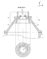
図10は、煙道突出部42の第1変形例を示す図である。本例の煙道突出部42は、複数の開口46を有する側壁47を有する。本例の開口46は、側壁47を貫通する円形の開口である。ただし、開口46は、メッシュ形状であってもよく、スリット形状であってもよい。排ガスは開口46を通過することができる。それゆえ、開口46を設けない場合と比較して、煙道突出部42を設けたことによる圧力損失を更に低減することができる。また、煙道突出部42は、開口46よりも径が大きい液体を、開口46において捕集することができる。
本例において、煙道突出部42の側壁47における各開口46の面積をS1とする。また、上部液返しリング50の各開口56の面積をS2とする。S2は、フランジ部52を上面視した場合の1つの開口56の面積とする。さらに、下部液返しリング70の各開口76の面積をS3とする。S3は、フランジ部72を上面視した場合の1つの開口76の面積とする。本例において、S1は、S2およびS3よりも小さい。液体の粒径は高さ方向において上に行くほど小さくなる傾向にある。それゆえ、S1をS2およびS3よりも大きくする場合と比較して、液体の捕集性能を向上させることができる。好適な例として、開口面積の大きさは、S1<S2<S3の関係を満たしてよい。
霧状となった液体は、排ガスの旋回流による遠心力によってレデューサ部30の内壁に押し付けられ、各開口56を通って自重で落下する。従って、自重で落下した液体の粒径は下に行くほど大きくなる傾向にある。液体は粒径が大きいほど重くなるので、排ガスの旋回流の影響が弱まる。これにより、より下に位置する各開口56ほど自重による液体の落下がさらに生じやすくなる。なお、本例の煙道突出部42を、第1、第3、第4および第6実施形態に適用してよいのは勿論である。
図11は、煙道突出部42の第2変形例を示す図である。煙道突出部42の少なくとも一部は、底部14側に向かって内径が増加する円錐台形状の筒状部を有してよい。本例の煙道突出部42は、その全体が高さ方向に進むにつれて内径が減少する円錐台形状の筒状部である。これにより、筒状部が円柱形状の筒である場合と比較して、煙道突出部42における圧力損失を更に低減することができる。
煙道突出部42は、円錐台形状の筒状部よりも内側に突出する煙道部液返しリング48をさらに有してよい。本例の煙道部液返しリング48は、レデューサ部30の小径部32から下方に突出する。本例の煙道部液返しリング48は、煙道部40における円筒形状の部分と所定の鈍角を形成してよい。本例では、レデューサ部30よりも上への液体の飛散を抑えることができるので、レデューサ部30よりも上の煙道部40の腐食を低減することができる。本例の煙道突出部42を、第1、第3、第4および第6実施形態に適用してよいのは勿論である。
図12(a)および図12(b)は、最も上部12側に位置する枝管22の噴射部24における主方向26を説明する図である。本例において、噴射部24から噴射される液体の主方向26は、噴射部24における噴射角度25の中心で規定する。なお、噴射角度25は、スプレーノズル等の噴射部24の近傍において液体が広がる角度として一般的に知られている。図12(a)は、最上部の噴射部24の主方向26がx‐y平面に対して平行である例である。これに対して、図12(b)は、最上部の噴射部24の主方向26が図12(a)の例よりも底部14側に傾いている例である。図12(b)の例では、図12(a)と比較して高さ方向へ飛散する液体を減少させることができる。これにより、上述の例と比較して、煙道部40から外へ液体が排出されることを抑制することができる。図12(b)の例を上述の実施形態および変形例に適用してよいのは勿論である。
図13は、第7実施形態における排ガス処理装置160の概要を示す図である。複数の枝管22のうち最上部に位置する枝管22は、レデューサ部30の内部に位置してよい。最上部に位置する枝管22は、レデューサ部30の小径部32と大径部34との間に設けられてよい。本例において、最上部に位置する枝管22は4つ存在する。本例において当該4つの枝管22は、高さ方向において上部液返しリング50とレデューサ部30の大径部34との間に設けられる。係る点が第6実施形態と異なる。他の点は、第6実施形態と同じである。本例では、レデューサ部30にまで枝管22を設けることにより、第6実施形態と比較して反応塔10の高さ方向長さを更に低減することができる。なお、最上部に位置する枝管22の噴射部24は、図12(b)のように主方向26が底部14側に傾いてよい。それにより、最上部の枝管22の噴射部24から噴射される液体が、下部液返しリング70に滞留することを抑制できる。
以上、本発明を実施の形態を用いて説明したが、本発明の技術的範囲は上記実施の形態に記載の範囲には限定されない。上記実施の形態に、多様な変更又は改良を加えることが可能であることが当業者に明らかである。その様な変更又は改良を加えた形態も本発明の技術的範囲に含まれ得ることが、請求の範囲の記載から明らかである。
請求の範囲、明細書、および図面中において示した装置、システム、プログラム、および方法における動作、手順、ステップ、および段階等の各処理の実行順序は、特段「より前に」、「先立って」等と明示しておらず、また、前の処理の出力を後の処理で用いるのでない限り、任意の順序で実現しうることに留意すべきである。請求の範囲、明細書、および図面中の動作フローに関して、便宜上「まず、」、「次に、」等を用いて説明したとしても、この順序で実施することが必須であることを意味するものではない。
10・・反応塔、11・・中心軸、12・・上部、14・・底部、15・・内部空間、16・・排ガス導入部、17・・内側側壁、18・・外側側壁、19・・排水導出部、20・・幹管、22・・枝管、24・・噴射部、25・・噴射角度、26・・主方向、28・・液体導入部、29・・バッフル、30・・レデューサ部、32・・小径部、34・・大径部、40・・煙道部、42・・煙道突出部、46・・開口、47・・側壁、48・・液返しリング、50・・上部液返しリング、52・・フランジ部、54・・筒状部、55・・内側面、56・・開口、57・・外側面、60・・上部液返し構造、70・・下部液返しリング、72・・フランジ部、74・・筒状部、76・・開口、100・・排ガス処理装置、110・・排ガス処理装置、120・・排ガス処理装置、130・・排ガス処理装置、140・・排ガス処理装置、150・・排ガス処理装置、160・・排ガス処理装置
Claims (15)
- 排ガスを処理する排ガス処理装置であって、
排ガスが導入される底部側から排ガスが排出される上部側への高さ方向に延伸する筒形状の内部空間を有し、旋回しながら上昇する排ガスに液体を噴射して洗浄する反応塔と、
前記反応塔よりも上に設けられ、前記反応塔に接続したレデューサ部と、
少なくとも一部が前記レデューサ部よりも上に設けられた煙道部と、
前記レデューサ部に設けられた上部液返し構造と
を備える
排ガス処理装置。 - 前記上部液返し構造は、前記煙道部の一部が前記レデューサ部に延伸して設けられた煙道突出部と、前記レデューサ部の内壁にリング状に設けられ、前記レデューサ部の内壁から突出する上部液返しリングとの少なくとも1以上を有する
請求項1に記載の排ガス処理装置。 - 前記上部液返し構造は、前記煙道突出部および前記上部液返しリングの両方を有し、
前記反応塔の内壁にリング状に設けられ、前記反応塔の内壁から突出する下部液返しリングをさらに備える
請求項2に記載の排ガス処理装置。 - 前記上部液返し構造は、前記煙道突出部および前記上部液返しリングのいずれか一方を有し、
前記反応塔の内壁にリング状に設けられ、前記反応塔の内壁から突出する下部液返しリングをさらに備える
請求項2に記載の排ガス処理装置。 - 前記煙道突出部、前記上部液返しリングおよび前記下部液返しリングの内径は、前記煙道突出部、前記上部液返しリングおよび前記下部液返しリングの順に小さい
請求項3または4に記載の排ガス処理装置。 - 前記上部液返しリングは、
前記レデューサ部の内壁に接するフランジ部と、
前記フランジ部の内径に接して設けられた筒状部と、
を有する
請求項2から5のいずれか一項に記載の排ガス処理装置。 - 前記上部液返しリングの前記筒状部は、前記レデューサ部の内壁と平行な内側面を有する円錐台形状である
請求項6に記載の排ガス処理装置。 - 前記上部液返しリングの前記フランジ部は、前記レデューサ部の内壁に直交して設けられる
請求項7に記載の排ガス処理装置。 - 前記上部液返しリングの前記筒状部は、前記反応塔の内壁と平行な内側面を有する円柱形状であり、
前記上部液返しリングの前記フランジ部は、前記レデューサ部の内壁に直交して設けられる
請求項6に記載の排ガス処理装置。 - 前記煙道突出部は、複数の開口を有する側壁を有する
請求項3または4に記載の排ガス処理装置。 - 前記煙道突出部の前記複数の開口における各開口の面積は、前記上部液返しリングに設けられた複数の開口における各開口の面積、および、前記下部液返しリングに設けられた複数の開口における各開口の面積よりも小さい
請求項10に記載の排ガス処理装置。 - 前記煙道突出部の少なくとも一部は、前記底部側に向かって内径が増加する円錐台形状の筒状部を有する
請求項10または11に記載の排ガス処理装置。 - 前記煙道突出部は、円錐台形状の前記筒状部よりも内側に突出する煙道部液返しリングをさらに有する
請求項12に記載の排ガス処理装置。 - 前記反応塔の前記内部空間において前記高さ方向に延伸し、液体を搬送する幹管と、
前記幹管の外壁から前記反応塔の内壁に向けて延伸して設けられ、各々異なる高さ位置に設けられた複数の枝管と、
前記複数の枝管に各々設けられ、前記幹管から供給される液体を噴射する複数の噴射部と
をさらに備え、
前記複数の枝管のうち最も前記上部側に位置する枝管において、前記液体を噴射する前記複数の噴射部における噴射角度の中心で規定される主方向は、前記底部側に傾いている
請求項1から13のいずれか一項に記載の排ガス処理装置。 - 前記複数の枝管のうち最上部に位置する枝管は、前記レデューサ部の内部に位置する
請求項14に記載の排ガス処理装置。
Applications Claiming Priority (2)
| Application Number | Priority Date | Filing Date | Title |
|---|---|---|---|
| JP2016051492A JP2019076798A (ja) | 2016-03-15 | 2016-03-15 | 排ガス処理装置 |
| JP2016-051492 | 2016-03-15 |
Publications (1)
| Publication Number | Publication Date |
|---|---|
| WO2017159099A1 true WO2017159099A1 (ja) | 2017-09-21 |
Family
ID=59850901
Family Applications (1)
| Application Number | Title | Priority Date | Filing Date |
|---|---|---|---|
| PCT/JP2017/003677 Ceased WO2017159099A1 (ja) | 2016-03-15 | 2017-02-01 | 排ガス処理装置 |
Country Status (2)
| Country | Link |
|---|---|
| JP (1) | JP2019076798A (ja) |
| WO (1) | WO2017159099A1 (ja) |
Cited By (5)
| Publication number | Priority date | Publication date | Assignee | Title |
|---|---|---|---|---|
| CN109999643A (zh) * | 2019-05-06 | 2019-07-12 | 新中天环保股份有限公司 | 一种脱酸塔烟气入口防堵降温装置及使用方法 |
| CN110141956A (zh) * | 2019-05-30 | 2019-08-20 | 广船国际有限公司 | 一种洗涤塔 |
| EP3875166A4 (en) * | 2019-06-28 | 2022-01-26 | Fuji Electric Co., Ltd. | EMISSION TREATMENT DEVICE AND SCRUB NOZZLE |
| CN115318047A (zh) * | 2022-08-12 | 2022-11-11 | 铜陵有色金属集团股份有限公司 | 烟气洗涤设备 |
| CN121155327A (zh) * | 2025-09-23 | 2025-12-19 | 湖北弘仪智能装备有限责任公司 | 一种船用废气处理装置 |
Families Citing this family (2)
| Publication number | Priority date | Publication date | Assignee | Title |
|---|---|---|---|---|
| JP7276518B2 (ja) * | 2020-01-21 | 2023-05-18 | 富士電機株式会社 | 排ガス処理装置 |
| JP2021137689A (ja) * | 2020-03-02 | 2021-09-16 | 富士電機株式会社 | 排ガス処理装置 |
Citations (6)
| Publication number | Priority date | Publication date | Assignee | Title |
|---|---|---|---|---|
| JPS6271516A (ja) * | 1985-09-24 | 1987-04-02 | Oji Koei Kk | 紙パルプ工場における排ガス脱硫装置 |
| JPS6320920U (ja) * | 1986-07-21 | 1988-02-12 | ||
| JPH11319480A (ja) * | 1998-05-21 | 1999-11-24 | Ishikawajima Harima Heavy Ind Co Ltd | 煙突一体型排煙脱硫装置 |
| JP2003001055A (ja) * | 1997-11-11 | 2003-01-07 | Mitsubishi Heavy Ind Ltd | 湿式ガス処理装置 |
| JP2011179767A (ja) * | 2010-03-02 | 2011-09-15 | Nippon Electric Glass Co Ltd | 排ガス処理装置および排ガス処理方法 |
| JP2014117685A (ja) * | 2012-12-19 | 2014-06-30 | Fuji Electric Co Ltd | 排ガス処理装置 |
-
2016
- 2016-03-15 JP JP2016051492A patent/JP2019076798A/ja not_active Withdrawn
-
2017
- 2017-02-01 WO PCT/JP2017/003677 patent/WO2017159099A1/ja not_active Ceased
Patent Citations (6)
| Publication number | Priority date | Publication date | Assignee | Title |
|---|---|---|---|---|
| JPS6271516A (ja) * | 1985-09-24 | 1987-04-02 | Oji Koei Kk | 紙パルプ工場における排ガス脱硫装置 |
| JPS6320920U (ja) * | 1986-07-21 | 1988-02-12 | ||
| JP2003001055A (ja) * | 1997-11-11 | 2003-01-07 | Mitsubishi Heavy Ind Ltd | 湿式ガス処理装置 |
| JPH11319480A (ja) * | 1998-05-21 | 1999-11-24 | Ishikawajima Harima Heavy Ind Co Ltd | 煙突一体型排煙脱硫装置 |
| JP2011179767A (ja) * | 2010-03-02 | 2011-09-15 | Nippon Electric Glass Co Ltd | 排ガス処理装置および排ガス処理方法 |
| JP2014117685A (ja) * | 2012-12-19 | 2014-06-30 | Fuji Electric Co Ltd | 排ガス処理装置 |
Cited By (5)
| Publication number | Priority date | Publication date | Assignee | Title |
|---|---|---|---|---|
| CN109999643A (zh) * | 2019-05-06 | 2019-07-12 | 新中天环保股份有限公司 | 一种脱酸塔烟气入口防堵降温装置及使用方法 |
| CN110141956A (zh) * | 2019-05-30 | 2019-08-20 | 广船国际有限公司 | 一种洗涤塔 |
| EP3875166A4 (en) * | 2019-06-28 | 2022-01-26 | Fuji Electric Co., Ltd. | EMISSION TREATMENT DEVICE AND SCRUB NOZZLE |
| CN115318047A (zh) * | 2022-08-12 | 2022-11-11 | 铜陵有色金属集团股份有限公司 | 烟气洗涤设备 |
| CN121155327A (zh) * | 2025-09-23 | 2025-12-19 | 湖北弘仪智能装备有限责任公司 | 一种船用废气处理装置 |
Also Published As
| Publication number | Publication date |
|---|---|
| JP2019076798A (ja) | 2019-05-23 |
Similar Documents
| Publication | Publication Date | Title |
|---|---|---|
| WO2017159099A1 (ja) | 排ガス処理装置 | |
| KR101570466B1 (ko) | 배기 가스 처리 장치 | |
| JP2019521841A (ja) | 排ガス中の硫黄酸化物量を低減させるシステム及び方法 | |
| CN106794417B (zh) | 废气处理装置 | |
| RU2018140015A (ru) | Устройство и способ для бункеровки топлива, устройство и способ для сепарации газа и жидкости в газожидкостном потоке | |
| US20200206678A1 (en) | A scrubber for cleaning of a gas | |
| WO2017159102A1 (ja) | 排ガス処理装置 | |
| WO2017203837A1 (ja) | 排ガス処理装置 | |
| WO2014014002A1 (ja) | ガス吸収塔 | |
| KR101782786B1 (ko) | 습식 탈황 장치 | |
| CN105944547B (zh) | 一种烟气超低排放吸收塔装置及应用 | |
| JP6139911B2 (ja) | 船舶用ミスト除去装置 | |
| CN107648993A (zh) | 一种高效的脱硫塔 | |
| TW202021662A (zh) | 氣液混合裝置及具備氣液混合裝置之排氣脫硫裝置 | |
| JP6588147B1 (ja) | 排ガス脱硫装置 | |
| JP5777651B2 (ja) | 排煙脱硫装置 | |
| CN115163491A (zh) | 真空泵排气装置 | |
| JP7390784B2 (ja) | ドレン排出装置 | |
| CN206631431U (zh) | 一种具有脱硫喷淋辅助装置的脱硫塔 | |
| JP5289668B2 (ja) | 湿式排煙脱硫装置 | |
| JP2016068029A (ja) | 気液接触装置 | |
| KR102252547B1 (ko) | 배기 가스 처리 장치 | |
| JP2016068030A (ja) | 噴霧ノズル及びその噴霧ノズルを備えた気液接触装置 | |
| CN116836735A (zh) | 一种脱硫塔煤气入口装置 | |
| CN106492593A (zh) | 烟气脱硫吸收塔 |
Legal Events
| Date | Code | Title | Description |
|---|---|---|---|
| NENP | Non-entry into the national phase |
Ref country code: DE |
|
| 121 | Ep: the epo has been informed by wipo that ep was designated in this application |
Ref document number: 17766107 Country of ref document: EP Kind code of ref document: A1 |
|
| 122 | Ep: pct application non-entry in european phase |
Ref document number: 17766107 Country of ref document: EP Kind code of ref document: A1 |
|
| NENP | Non-entry into the national phase |
Ref country code: JP |