WO2017159018A1 - 眼科装置 - Google Patents
眼科装置 Download PDFInfo
- Publication number
- WO2017159018A1 WO2017159018A1 PCT/JP2017/001113 JP2017001113W WO2017159018A1 WO 2017159018 A1 WO2017159018 A1 WO 2017159018A1 JP 2017001113 W JP2017001113 W JP 2017001113W WO 2017159018 A1 WO2017159018 A1 WO 2017159018A1
- Authority
- WO
- WIPO (PCT)
- Prior art keywords
- optical system
- unit
- alignment
- eye
- inspection
- Prior art date
- Legal status (The legal status is an assumption and is not a legal conclusion. Google has not performed a legal analysis and makes no representation as to the accuracy of the status listed.)
- Ceased
Links
Images


Classifications
-
- A—HUMAN NECESSITIES
- A61—MEDICAL OR VETERINARY SCIENCE; HYGIENE
- A61B—DIAGNOSIS; SURGERY; IDENTIFICATION
- A61B3/00—Apparatus for testing the eyes; Instruments for examining the eyes
- A61B3/10—Objective types, i.e. instruments for examining the eyes independent of the patients' perceptions or reactions
- A61B3/14—Arrangements specially adapted for eye photography
- A61B3/15—Arrangements specially adapted for eye photography with means for aligning, spacing or blocking spurious reflection ; with means for relaxing
- A61B3/152—Arrangements specially adapted for eye photography with means for aligning, spacing or blocking spurious reflection ; with means for relaxing for aligning
-
- A—HUMAN NECESSITIES
- A61—MEDICAL OR VETERINARY SCIENCE; HYGIENE
- A61B—DIAGNOSIS; SURGERY; IDENTIFICATION
- A61B3/00—Apparatus for testing the eyes; Instruments for examining the eyes
- A61B3/10—Objective types, i.e. instruments for examining the eyes independent of the patients' perceptions or reactions
-
- A—HUMAN NECESSITIES
- A61—MEDICAL OR VETERINARY SCIENCE; HYGIENE
- A61B—DIAGNOSIS; SURGERY; IDENTIFICATION
- A61B3/00—Apparatus for testing the eyes; Instruments for examining the eyes
- A61B3/0075—Apparatus for testing the eyes; Instruments for examining the eyes provided with adjusting devices, e.g. operated by control lever
-
- A—HUMAN NECESSITIES
- A61—MEDICAL OR VETERINARY SCIENCE; HYGIENE
- A61B—DIAGNOSIS; SURGERY; IDENTIFICATION
- A61B3/00—Apparatus for testing the eyes; Instruments for examining the eyes
- A61B3/10—Objective types, i.e. instruments for examining the eyes independent of the patients' perceptions or reactions
- A61B3/102—Objective types, i.e. instruments for examining the eyes independent of the patients' perceptions or reactions for optical coherence tomography [OCT]
-
- A—HUMAN NECESSITIES
- A61—MEDICAL OR VETERINARY SCIENCE; HYGIENE
- A61B—DIAGNOSIS; SURGERY; IDENTIFICATION
- A61B3/00—Apparatus for testing the eyes; Instruments for examining the eyes
- A61B3/10—Objective types, i.e. instruments for examining the eyes independent of the patients' perceptions or reactions
- A61B3/12—Objective types, i.e. instruments for examining the eyes independent of the patients' perceptions or reactions for looking at the eye fundus, e.g. ophthalmoscopes
- A61B3/1225—Objective types, i.e. instruments for examining the eyes independent of the patients' perceptions or reactions for looking at the eye fundus, e.g. ophthalmoscopes using coherent radiation
- A61B3/1233—Objective types, i.e. instruments for examining the eyes independent of the patients' perceptions or reactions for looking at the eye fundus, e.g. ophthalmoscopes using coherent radiation for measuring blood flow, e.g. at the retina
-
- A—HUMAN NECESSITIES
- A61—MEDICAL OR VETERINARY SCIENCE; HYGIENE
- A61B—DIAGNOSIS; SURGERY; IDENTIFICATION
- A61B3/00—Apparatus for testing the eyes; Instruments for examining the eyes
- A61B3/10—Objective types, i.e. instruments for examining the eyes independent of the patients' perceptions or reactions
- A61B3/14—Arrangements specially adapted for eye photography
- A61B3/15—Arrangements specially adapted for eye photography with means for aligning, spacing or blocking spurious reflection ; with means for relaxing
Definitions
- the present invention relates to an ophthalmologic apparatus for optically inspecting an eye to be examined.
- an optical coherence tomography that obtains a tomographic image using optical coherence tomography (OCT) is well known.
- the alignment between the examination optical system (apparatus optical system) and the eye to be examined is extremely important from the viewpoint of the accuracy and accuracy of the examination.
- This alignment is called alignment.
- an operation for aligning the optical axis of the inspection optical system with respect to a reference position (for example, the center of the cornea) of the eye to be examined xy alignment
- an operation for adjusting the distance between the eye to be examined and the optical system for inspection z Alignment
- Patent Document 1 the anterior eye part of the eye to be examined is photographed from two or more photographing parts from different directions, and two or more photographed images obtained by this photographing are analyzed to obtain the three-dimensional position of the eye to be examined.
- An ophthalmologic apparatus is described that adjusts the alignment of an inspection optical system with respect to an eye to be examined based on the results.
- an ophthalmologic apparatus that obtains a tomographic image using OCT is also used for measuring blood flow information of blood flowing through the blood vessels of the fundus of the eye to be examined.
- the velocity of the fundus blood flow is calculated using the Doppler shift OCT technique, the angle formed by the incident direction of the signal light with respect to the eye to be examined and the direction in which the blood vessel of the fundus extends is 90 °.
- the blood flow velocity cannot be calculated (see Patent Document 2). For this reason, when blood flow information is measured, it is necessary to take a tomographic image of the fundus with the optical axis of the optical system for examination shifted from the reference position of the eye to be examined.
- the amount of misalignment in the xy direction of the inspection optical system with respect to the eye to be examined is detected from the captured image of the eye to be examined. It is necessary to calculate the alignment position in the z direction of the inspection optical system based on the detection result of the misalignment amount. For this reason, in the ophthalmologic apparatus described in Patent Document 3, it takes time to determine the alignment position in the z direction that can suppress the occurrence of flare. Note that the time required for this determination can be shortened by using a high-performance arithmetic processing device, but in this case, there arises a problem that the manufacturing cost of the ophthalmic device increases.
- An object of the present invention is to provide an ophthalmologic apparatus capable of suppressing the occurrence of flare.
- An ophthalmologic apparatus for achieving an object of the present invention includes an imaging unit that images an observation site of an eye to be inspected through an inspection optical system, alignment in the optical axis direction of the inspection optical system with respect to the test eye, and perpendicular to the optical axis direction.
- a first alignment unit that performs alignment in the direction
- an optical system moving unit that moves the inspection optical system from the first position aligned by the first alignment unit to a second position shifted at least in the vertical direction, and a first position
- the alignment position in the optical axis direction of the inspection optical system with respect to the eye to be examined at the second position is determined, and the inspection optical system is moved to the alignment position along the optical axis direction.
- a second alignment unit is used to determine the alignment position along the optical axis direction.
- the alignment position in the optical axis direction of the optical system for inspection with respect to the eye to be examined at the second position can be determined based on the position difference between the first position and the second position.
- the alignment position can be determined easily and at high speed.
- the inspection optical system divides the light emitted from the light source into signal light and reference light, irradiates the signal light to the site to be observed, and
- An optical path length changing unit that includes an interference optical system that guides interference light between the reflected signal light and the reference light to the imaging unit, and is provided in the interference optical system and changes an optical path length of at least one of the signal light and the reference light;
- An adjustment control unit that controls the optical path length changing unit to adjust the optical path length according to the distance and direction in which the inspection optical system moves in the optical axis direction by alignment by the second alignment unit.
- An ophthalmologic apparatus comprises a base and a base supported so as to be movable at least in a vertical direction with respect to the base, and the inspection optical system and the imaging unit are disposed on the base
- the optical system moving unit moves the inspection optical system from the first position to the second position by moving the gantry.
- the inspection optical system can be moved from the first position to the second position simply by moving the gantry, and the alignment position can be determined based on the moving direction and the moving amount of the gantry.
- the ophthalmologic apparatus includes a storage unit that stores a correspondence relationship between a position difference and an alignment position, and the second alignment unit refers to the correspondence relationship stored in the storage unit based on the position difference. To determine the alignment position. As a result, the alignment position can be determined more easily and faster than in the past.
- an eye position acquisition unit that acquires a three-dimensional position of an eye to be inspected, and an inspection optical system for the eye to be inspected based on the three-dimensional position acquired by the eye position acquisition unit.
- a positional deviation information acquisition unit that acquires positional deviation information in the optical axis direction and the vertical direction, and the first alignment unit performs inspection by automatic control or manual control based on the positional deviation information acquired by the positional deviation information acquisition unit. Align the optical system. Thereby, the inspection optical system can be aligned with the reference position of the eye to be examined.
- the ophthalmologic apparatus according to the present invention can suppress the occurrence of flare at a lower cost and in a shorter time than conventional when imaging is performed in a state where the optical axis of the inspection optical system is shifted from the reference position of the eye to be examined. .
- FIG. 1 It is the schematic diagram which showed the illumination light beam area and imaging
- (A) is a schematic diagram showing an illumination light beam area and a photographing light beam area of the ophthalmologic apparatus when the inspection optical system is moved from the first position to the second position, and
- (B) is a code in (A). It is an enlarged view of the area
- C) is an enlarged view of the area
- (A) is the schematic diagram which showed the illumination light beam area and imaging
- (B) is an enlarged view of the area
- C) is an enlarged view of a region indicated by reference numeral G2 in (A).
- It is a flowchart which shows the flow of a measurement process of the blood flow information of the fundus by the ophthalmologic apparatus. It is a flowchart which shows the flow of the blood flow information measurement process of the fundus in the comparative example.
- an ophthalmologic apparatus according to the present invention will be described in detail with reference to the drawings.
- the ophthalmologic apparatus according to the present invention is used for optical examination of an eye to be examined.
- an optical coherence tomography will be described as an example of such an ophthalmologic apparatus.
- images (tomographic images) acquired by OCT may be collectively referred to as OCT images.
- a measurement operation for forming an OCT image may be referred to as OCT measurement.
- OCT measurement it is possible to use suitably the description content of the literature described in this specification as the content of the following embodiment.
- an optical coherence tomography using a spectral domain type OCT equipped with a low-coherence light source and a spectroscope will be described.
- other types for example, a swept source type or an infath type are described.
- the present invention can be applied to an optical coherence tomography using the OCT method.
- the swept source OCT scans (wavelength sweeps) the wavelength of the light irradiated to the object to be measured, and detects the interference light obtained by superimposing the reflected light of each wavelength and the reference light.
- a spectrum intensity distribution is acquired, and a Fourier transform is performed on the spectrum intensity distribution, thereby imaging the form of the object to be measured.
- In-face OCT is a technique for irradiating an object to be measured with light having a predetermined beam diameter, and analyzing a component of interference light obtained by superimposing the reflected light and reference light to obtain a light beam.
- This is a method of forming an image of the object to be measured in a cross section orthogonal to the traveling direction of the head, and is also called a full-field type.
- an apparatus combining an OCT apparatus and a fundus camera will be described.
- the application target of the present invention is not limited to such a multi-function apparatus, and the present invention is applied to an ophthalmologic apparatus as a single machine. It is also possible to do.
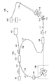
- FIG. 1 is a schematic diagram illustrating an example of the configuration of the ophthalmologic apparatus 1.
- the ophthalmologic apparatus 1 includes a fundus camera unit 2, a display device 3, an OCT unit 100, and an arithmetic control unit 200.
- the retinal camera unit 2 has almost the same optical system as a conventional retinal camera.
- the OCT unit 100 is provided with an interference optical system 100a (see FIG. 2) for acquiring an OCT image of the fundus oculi Ef of the eye E to be examined (corresponding to an observation site of the present invention).
- the imaging optical system 30 of the fundus camera unit 2 and the interference optical system 100a of the OCT unit 100 constitute the inspection optical system 1a of the present invention.
- the arithmetic control unit 200 includes a computer that executes various arithmetic processes and control processes.
- the fundus camera unit 2 is provided with an optical system for acquiring a two-dimensional image (fundus image) representing the surface form of the fundus oculi Ef.
- the fundus image includes an observation image and a captured image.
- the observation image is a monochrome moving image formed at a predetermined frame rate using, for example, near infrared light.
- the fundus camera unit 2 can obtain an observation image of the anterior segment Ea.
- the captured image may be, for example, a color image obtained by flashing visible light, or a monochrome still image using near infrared light or visible light as illumination light.
- the fundus camera unit 2 may be configured to be able to acquire images other than these, such as a fluorescein fluorescent image, an indocyanine green fluorescent image, or a spontaneous fluorescent image.
- the fundus camera unit 2 is provided with an illumination optical system 10 and a photographing optical system 30.
- the illumination optical system 10 irradiates the fundus oculi Ef with illumination light.
- the photographing optical system 30 guides the fundus reflection light of the illumination light to CCD (Charge-Coupled Device) -type or CMOS (complementary-metal-oxide-semiconductor) -type image sensors 35,.
- the imaging optical system 30 guides the signal light from the OCT unit 100 to the fundus oculi Ef and guides the signal light passing through the fundus oculi Ef to the OCT unit 100.
- the observation light source 11 of the illumination optical system 10 is composed of, for example, a halogen lamp.
- the light (observation illumination light) output from the observation light source 11 is reflected by the reflection mirror 12 having a curved reflection surface, and passes through the visible cut filter 14 via the condenser lens 13, whereby near infrared light. It becomes. Further, the observation illumination light is once converged in the vicinity of the photographing light source 15, reflected by the mirror 16, and passes through the relay lenses 17 and 18, the stop 19, and the relay lens 20. Then, the observation illumination light is reflected by the peripheral part of the aperture mirror 21 (region around the aperture part), passes through the dichroic mirror 46, and is refracted by the objective lens 22 to illuminate the fundus oculi Ef.
- An LED Light (Emitting Diode) may be used as the observation light source.
- the fundus reflection light of the observation illumination light is refracted by the objective lens 22, passes through the dichroic mirror 46, the hole formed in the center region of the aperture mirror 21, and the dichroic mirror 55, and passes through the focusing lens 31. Then, it is reflected by the mirror 32. Further, the fundus reflection light passes through the half mirror 39 ⁇ / b> A, is reflected by the dichroic mirror 33, and forms an image on the light receiving surface of the image sensor 35 by the condenser lens 34.
- the image sensor 35 detects fundus reflection light at a predetermined frame rate, for example. On the display device 3, an image (observation image) based on the fundus reflection light detected by the image sensor 35 is displayed. Note that, when the photographing optical system is focused on the anterior segment Ea, an observation image of the anterior segment Ea is displayed on the display device 3.
- the photographing light source 15 is constituted by, for example, a xenon lamp.
- the light (imaging illumination light) output from the imaging light source 15 is applied to the fundus oculi Ef through the same path as the observation illumination light.
- the fundus reflection light of the photographic illumination light is guided to the dichroic mirror 33 through the same path as the observation illumination light, passes through the dichroic mirror 33, is reflected by the mirror 36, and is reflected by the condenser lens 37 of the image sensor 38.
- An image is formed on the light receiving surface.
- an image (captured image) based on fundus reflection light detected by the image sensor 38 is displayed.
- the display device 3 that displays the observation image and the display device 3 that displays the captured image may be the same or different.
- a captured image of infrared light is displayed. It is also possible to use an LED as a photographing light source.
- the LCD 39 displays a fixation target or a visual acuity measurement index.
- the fixation target is an index for fixing the eye E to be examined, and is used at the time of fundus photographing and OCT measurement.
- a part of the light output from the LCD 39 is sequentially reflected by the half mirror 39A and the mirror 32, and then sequentially passes through the focusing lens 31, the dichroic mirror 55, the aperture of the aperture mirror 21, and the dichroic mirror 46.
- the light is refracted by the objective lens 22 and projected onto the fundus oculi Ef.
- the projection direction of the fixation target with respect to the eye E that is, the fixation position of the eye E can be changed.
- the fixation position of the eye E for example, as in a conventional fundus camera, a position for acquiring an image centered on the macular portion of the fundus oculi Ef, a position for acquiring an image centered on the optic disc, And a position for acquiring an image centered on the fundus center between the macula and the optic disc. It is also possible to arbitrarily change the display position of the fixation target.
- the means for projecting the fixation target onto the eye E is not limited to this.
- the fundus camera unit 2 is provided with a focus optical system 60.
- the focus optical system 60 generates an index (split index) for focusing on the fundus oculi Ef.
- the reflecting surface of the reflecting rod 67 is obliquely provided on the optical path of the illumination optical system 10.
- the light (focus light) output from the LED 61 of the focus optical system 60 passes through the relay lens 62, is separated into two light beams by the split indicator plate 63, passes through the two-hole aperture 64, and is reflected by the mirror 65, The light is focused on the reflecting surface of the reflecting bar 67 by the condenser lens 66 and reflected. Further, the focus light passes through the relay lens 20, is reflected by the perforated mirror 21, passes through the dichroic mirror 46, is refracted by the objective lens 22, and is projected onto the fundus oculi Ef.
- the fundus reflection light of the focus light is detected by the image sensor 35 through the same path as the observation illumination light.
- the light reception image (split indicator) by the image sensor 35 is displayed on the display device 3 together with the observation image.
- the arithmetic control unit 200 analyzes the position of the split index and moves the focusing lens 31 and the focus optical system 60 to automatically perform focusing as in the conventional case (autofocus function). Alternatively, focusing may be performed manually while visually checking the split indicator.
- the dichroic mirror 46 branches the optical path for OCT measurement from the optical path for fundus imaging.
- the dichroic mirror 46 reflects light in a wavelength band used for OCT measurement and transmits light for fundus photographing.
- a collimator lens unit 40, an optical path length changing unit 41, a galvano scanner 42, a focusing lens 43, a mirror 44, and a relay lens 45 are provided in this order from the OCT unit 100 side. It has been. These constitute a part of the above-described interference optical system 100a.
- the optical path length changing unit 41 is movable in the direction of the arrow shown in FIG. 1, and changes the optical path length of an optical path for OCT measurement (signal light LS described later, see FIG. 2). This change of the optical path length is used for correcting the optical path length according to the axial length of the eye E and adjusting the interference state.
- the optical path length changing unit 41 includes, for example, a corner cube and a mechanism for moving the corner cube.
- the galvano scanner 42 changes the traveling direction of light (signal light LS, see FIG. 2) passing through the optical path for OCT measurement.
- the galvano scanner 42 includes, for example, a galvanometer mirror that scans the signal light LS in the x direction, a galvanometer mirror that scans in the y direction, and a mechanism that independently drives them. Thereby, the fundus oculi Ef can be scanned with the signal light LS.
- the fundus camera unit 2 is provided with an anterior eye camera 300.
- the anterior segment camera 300 images the anterior segment Ea substantially simultaneously from different directions.
- two cameras are provided on the surface of the fundus camera unit 2 on the subject side (see anterior eye cameras 300A and 300B shown in FIG. 5A).
- the anterior eye cameras 300A and 300B are provided at positions deviating from the optical path of the illumination optical system 10 and the optical path of the photographing optical system 30, respectively.
- the two anterior eye cameras 300 ⁇ / b> A and 300 ⁇ / b> B may be collectively represented by reference numeral 300.
- the two anterior eye cameras 300A and 300B are provided, but the number of the anterior eye cameras 300 may be an arbitrary number of two or more.
- the anterior segment camera 300 is provided separately from the illumination optical system 10 and the imaging optical system 30, but at least the imaging optical system 30 can be used to perform similar anterior segment imaging. . That is, one of the two or more anterior segment cameras may include the photographing optical system 30.
- substantially simultaneously indicates that a photographing timing shift that allows negligible eye movement is allowed in photographing with two or more anterior segment cameras. Thereby, the image when the eye E is substantially at the same position (orientation) can be acquired by the two or more anterior eye cameras 300.
- the shooting by the two or more anterior eye cameras 300 may be either moving image shooting or still image shooting.
- substantially simultaneous anterior ocular shooting is realized by controlling the shooting start timing to match or controlling the frame rate and shooting timing of each frame.
- this can be realized by controlling to match the shooting timing.
- the alignment (alignment) of the inspection optical system 1a with respect to the eye E is performed using the two anterior eye cameras 300A and 300B.
- FIG. 2 is a schematic diagram illustrating an example of the configuration of the OCT unit 100. As shown in FIG. 2, the OCT unit 100 is provided with an interference optical system 100a for acquiring an OCT image of the fundus oculi Ef.
- the interference optical system 100a has the same configuration as a conventional spectral domain type OCT apparatus. That is, the interference optical system 100a divides the low-coherence light into the reference light LR and the signal light (also referred to as measurement light) LS, and then the signal light LS that passes through the fundus oculi Ef and the reference light LR that passes through the reference light path. To generate interference light LC and detect a spectral component of the interference light LC.
- the well-known technique according to the type of OCT can be applied arbitrarily.
- a wavelength swept light source is provided instead of a light source that outputs a low coherence light source, and an optical member that spectrally decomposes interference light is not provided.
- the light source unit 101 outputs a broadband low-coherence light L0.
- the low coherence light L0 includes, for example, a near-infrared wavelength band (about 800 nm to 900 nm) and has a temporal coherence length of about several tens of micrometers. Note that near-infrared light having a wavelength band invisible to the human eye, for example, a center wavelength of about 1040 to 1060 nm, may be used as the low-coherence light L0.
- the light source unit 101 includes a light output device such as a super luminescent diode (Super Luminescent Diode: SLD), an LED, and an SOA (Semiconductor Optical Amplifier).
- a light output device such as a super luminescent diode (Super Luminescent Diode: SLD), an LED, and an SOA (Semiconductor Optical Amplifier).
- the low coherence light L0 output from the light source unit 101 is guided to the fiber coupler 103 by the optical fiber 102, and is divided into the signal light LS and the reference light LR.
- the reference light LR is guided by the optical fiber 104 and reaches an optical attenuator (attenuator) 105.
- the optical attenuator 105 automatically adjusts the amount of the reference light LR guided to the optical fiber 104 under the control of the arithmetic control unit 200.
- the reference light LR whose light amount has been adjusted by the optical attenuator 105 is guided by the optical fiber 104 and reaches the polarization adjuster (polarization controller) 106.
- the polarization adjuster 106 adjusts the polarization state of the reference light LR guided through the optical fiber 104 by, for example, applying external stress to the looped optical fiber 104.
- the configuration of the polarization adjuster 106 is not limited to this, and any known technique can be used.
- the reference light LR whose polarization state is adjusted by the polarization adjuster 106 reaches the fiber coupler 109.
- the signal light LS generated by the fiber coupler 103 is guided by the optical fiber 107 and converted into a parallel light beam by the collimator lens unit 40. Furthermore, the signal light LS reaches the dichroic mirror 46 via the optical path length changing unit 41, the galvano scanner 42, the focusing lens 43, the mirror 44, and the relay lens 45 as shown in FIG.
- the signal light LS is reflected by the dichroic mirror 46, is refracted by the objective lens 22, and is applied to the fundus oculi Ef.
- the signal light LS is scattered (including reflection) at various depth positions of the fundus oculi Ef.
- the backscattered light of the signal light LS from the fundus oculi Ef travels in the same direction as the forward path in the reverse direction, is guided to the fiber coupler 103, and reaches the fiber coupler 109 via the optical fiber 108.
- the fiber coupler 109 generates the interference light LC by causing the backscattered light of the signal light LS and the reference light LR that has passed through the optical fiber 104 to interfere with each other.
- the interference light LC is guided by the optical fiber 110 and is emitted from the emission end 111. Further, the interference light LC is converted into a parallel light beam by the collimator lens 112, dispersed (spectral decomposition) by the diffraction grating 113, condensed by the condenser lens 114, and projected onto the light receiving surface of the CCD type or CMOS type image sensor 115.
- the diffraction grating 113 shown in FIG. 2 is a transmission type, other types of spectroscopic elements such as a reflection type diffraction grating may be used.
- the image sensor 115 corresponds to the photographing unit of the present invention, and for example, a line sensor is used.
- the CCD type image sensor 115 detects each spectral component of the separated interference light LC and converts it into electric charges. Then, the image sensor 115 accumulates this electric charge, generates a detection signal, and sends it to the arithmetic control unit 200. Thereby, an OCT image of the fundus oculi Ef is obtained. Then, by moving the optical path length changing unit 41 described above and changing the optical path length difference between the signal light LS and the reference light LR, OCT images of various depths of the fundus oculi Ef are obtained.
- the optical path length of the signal light LS is changed by the optical path length changing unit 41.
- the optical system itself that contributes to OCT measurement is moved relative to the eye E by moving the optical system itself.
- the optical path length can be changed.
- a reflection mirror reference mirror
- this reference mirror is moved in the traveling direction of the reference light LR, thereby The optical path length may be changed.
- the change of the optical path length of the signal light LS and the change of the optical path length of the reference light LR may be combined.
- the arithmetic control unit 200 analyzes the detection signal input from the image sensor 115 to form an OCT image of the fundus oculi Ef, and displays the OCT image of the fundus oculi Ef on the display device 3.
- the arithmetic processing for forming an OCT image is the same as that of a conventional spectral domain type OCT apparatus.
- the arithmetic control unit 200 controls the operation of each part of the fundus camera unit 2 and the OCT unit 100.
- the arithmetic control unit 200 controls the fundus camera unit 2 by controlling the operation of the observation light source 11, the operation control of the imaging light source 15, the operation control of the LED 61, the operation control of the LCD 39, the movement control of the focusing lenses 31 and 43, and the reflector. 67 movement control, focus optical system 60 movement control, optical path length changing unit 41 movement control, galvano scanner 42 operation control, anterior eye camera 300 operation control, and the like.
- the arithmetic control unit 200 performs operation control of the light source unit 101, operation control of the optical attenuator 105, operation control of the polarization adjuster 106, operation control of the image sensor 115, and the like as control of the OCT unit 100.
- the arithmetic control unit 200 includes, for example, a microprocessor, a RAM (Random Access Memory), a ROM (Read Only Memory), a hard disk drive, a communication interface, and the like, as in a conventional computer.
- a computer program and data for controlling the ophthalmologic apparatus 1 are stored in a storage device such as a hard disk drive.
- the arithmetic control unit 200 may include various circuit boards, for example, a circuit board for forming an OCT image.
- the arithmetic control unit 200 may include an operation device (input device) such as a keyboard and a mouse, and a display device such as an LCD.
- the fundus camera unit 2, the display device 3, the OCT unit 100, and the arithmetic control unit 200 may be configured integrally (that is, in a single casing) or separated into two or more casings. May be.
- the arithmetic control unit 200 (ophthalmologic apparatus 1) of the present embodiment performs blood flow information measurement for generating blood flow information related to the blood vessel of interest in the fundus oculi Ef.
- blood flow information is information relating to blood flow such as information indicating blood flow velocity and blood flow volume.
- first scanning and second scanning are performed on the fundus oculi Ef.
- first scan the first cross section that intersects the target blood vessel of the fundus oculi Ef is repeatedly scanned with the signal light LS.
- second scan the second cross section that intersects the target blood vessel and is located in the vicinity of the first cross section is scanned with the signal light LS.
- the first cross section and the second cross section are preferably orthogonal to the traveling direction of the blood vessel of interest.
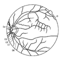
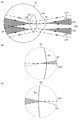
- FIG. 3 is an explanatory diagram for explaining an example of the first scan and the second scan at the time of blood flow information measurement.
- one first cross section C0 and two second cross sections C1 and C2 form a predetermined blood vessel Db in the vicinity of the optic disc Da of the fundus oculi Ef. Set to intersect.
- One of the two second cross sections C1 and C2 is located upstream of the target blood vessel Db with respect to the first cross section C0, and the other is located downstream.
- the first scan is preferably performed over at least one cardiac cycle of the patient's heart, for example. Thereby, blood flow information in all time phases of the heart is obtained.
- the time for executing the first scan may be a predetermined time set in advance, or may be set for each patient or for each examination. In the former case, a time longer than a general cardiac cycle is set (for example, 2 seconds). In the latter case, examination data such as a patient's electrocardiogram is referred to.
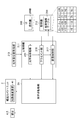
- FIG. 4 is a block diagram illustrating a configuration of the arithmetic control unit 200 that is a control system of the ophthalmologic apparatus 1.
- control unit 210 includes, for example, the above-described microprocessor, RAM, ROM, hard disk drive, communication interface, and the like.
- the control unit 210 includes a main control unit 211, a storage unit 212, and an optical system position acquisition unit 213.
- the main control unit 211 performs the various operation controls described above.
- the movement control of the focusing lens 31 is to move the focusing lens 31 in the optical axis direction by controlling a focusing drive unit (not shown). Thereby, the focus position of the photographic optical system 30 is changed.
- the main control unit 211 controls the optical system driving unit 2A to move the examination optical system 1a (fundus camera unit 2, OCT unit 100) of the ophthalmologic apparatus 1 three-dimensionally, and also the optical path length described above.
- the changing unit 41 is moved in the direction of the arrow shown in FIG.
- the main control unit 211 can move the anterior eye camera 300 by controlling the optical system driving unit 2A.
- An imaging moving unit that can independently move two or more anterior eye cameras 300 can be provided.
- the main control unit 211 performs a process of writing data to the storage unit 212 and a process of reading data from the storage unit 212.
- the storage unit 212 stores various data. Examples of data stored in the storage unit 212 include OCT image image data, fundus image data, eye information, and a position information table 219 (see FIG. 9) described later.
- the eye information includes patient information related to the subject such as patient ID (identification) and name, and information related to the eye such as left / right eye identification information.
- the storage unit 212 stores various programs and data for operating the ophthalmologic apparatus 1. Although described in detail later, the position information table 219 is used for alignment of the inspection optical system 1a at the time of blood flow information measurement.
- aberration information (not shown) is stored in the storage unit 212 in advance.
- information on distortion aberration generated in the captured image due to the influence of the optical system mounted on each anterior segment camera 300 is recorded.
- the optical system mounted on the anterior segment camera 300 includes an optical element that generates distortion, such as a lens.
- the aberration information can be said to be a parameter obtained by quantifying the distortion that these optical elements give to the photographed image.
- a specific example of a method for generating aberration information is described in, for example, Japanese Patent Application Laid-Open No. 2013-248376 by the applicant of the present application, and detailed description thereof is omitted.
- the optical system position acquisition unit 213 acquires the current position of the inspection optical system 1 a mounted on the ophthalmic apparatus 1.
- the inspection optical system 1a is an optical system used for optically inspecting the eye E.
- the imaging optical system 30 of the fundus camera unit 2 and the interference optical system 100a of the OCT unit 100 are used. Including.
- the optical system position acquisition unit 213 receives, for example, information indicating the content of movement control of the optical system driving unit 2A from the main control unit 211, and the current position of the inspection optical system 1a moved by the optical system driving unit 2A. To get. A specific example of this process will be described.
- the main control unit 211 controls the optical system driving unit 2A at a predetermined timing (when the apparatus is activated, when patient information is input, etc.) to move the examination optical system 1a to a predetermined initial position. Thereafter, each time the optical system driving unit 2A is controlled, the main control unit 211 records the control contents. Thereby, a history of control contents is obtained.
- the optical system position acquisition unit 213 acquires the control content up to the present with reference to this history, and obtains the current position of the inspection optical system 1a based on the control content.
- the control content is transmitted to the optical system position acquisition unit 213, and each time the optical system position acquisition unit 213 receives the control content, the inspection optical system is transmitted.
- the current position may be obtained sequentially.
- a position sensor that detects the position of the inspection optical system may be provided in the optical system position acquisition unit 213.
- the main control unit 211 determines the acquired current position and the eye to be examined obtained by the analysis unit 231 described later. Based on the three-dimensional position of E, it is possible to acquire positional deviation information of the inspection optical system 1a with respect to the eye E. Specifically, the main control unit 211 recognizes the current position of the inspection optical system 1 a based on the acquisition result by the optical system position acquisition unit 213, and recognizes the three-dimensional position of the eye E based on the analysis result by the analysis unit 231. .
- the main control unit 211 determines the x direction from the appropriate position of the inspection optical system 1a with respect to the eye E based on the current position of the inspection optical system 1a and the three-dimensional position recognized by the analysis unit 231.
- the positional deviation information including the positional deviation amount and the positional deviation direction in the left-right direction), the y-direction (vertical direction), and the z-direction (working distance direction) is acquired.
- the main control unit 211 functions as a positional deviation information acquisition unit of the present invention.
- the main control unit 211 performs an inspection for the reference position (for example, the center of the cornea) of the eye E by automatic control or manual control according to the acquired position shift information (position shift amount and position shift direction in each direction).
- the optical system 1a is aligned (hereinafter abbreviated as first alignment).
- the main control unit 211 functions as the first alignment unit of the present invention together with the optical system driving unit 2A.
- the first alignment includes alignment in the direction (x, y direction) perpendicular to the optical axis direction (z direction) of the inspection optical system 1a and alignment in the optical axis direction.
- the optical axis direction (z direction) of the inspection optical system 1a is the direction of light (signal light LS, etc.) emitted from the objective lens 22 to the eye E, and the inspection optical axis (imaging optical axis). ) Direction.
- the main control unit 211 controls the optical system driving unit 2A so that the position of the inspection optical system 1a with respect to the three-dimensional position of the eye E to be inspected has a predetermined positional relationship, and the inspection optical The position is changed starting from the current position of the system 1a.
- This predetermined positional relationship is such that the positions in the x direction and the y direction coincide with each other, and the distance in the z direction becomes a predetermined working distance.
- the main control unit 211 when performing the manual control, observes the alignment index image at a predetermined position on the screen of the display unit 240A according to the acquired positional shift information (the positional shift amount and the positional shift direction in each direction). Overlay the image and display it.
- the alignment index image changes in display position, size, and the like according to the amount of displacement and the direction of displacement in each direction of the inspection optical system 1a with respect to the eye E.
- the user operates the operation unit 240B while confirming the alignment index image displayed on the screen of the display unit 240A.
- the main control unit 211 performs the first alignment by driving the optical system driving unit 2A and moving the inspection optical system 1a in a three-dimensional manner.
- the image forming unit 220 Based on the detection signal from the image sensor 115, the image forming unit 220 forms image data of an OCT image (tomographic image) of the fundus oculi Ef and image data of a phase image. These images will be described later.
- the image forming unit 220 includes, for example, the above-described circuit board or microprocessor. In this specification, “image data” and “image” based thereon may be identified.
- the image forming unit 220 includes an OCT image forming unit 221 and a phase image forming unit 222.
- the OCT image forming unit 221 forms an OCT image (first OCT image) representing a time-series change in form in the first cross section C0 based on the detection result of the interference light LC obtained by the first scanning.
- the OCT image forming unit 221 includes an OCT image (second OCT image) representing the form in the second cross section C1 based on the detection result of the interference light LC obtained by the second scanning with respect to the second cross sections C1 and C2, and the first An OCT image (second OCT image) representing the form in the two cross sections C2 is formed.
- Patent Document 2 Japanese Patent Application Laid-Open No. 2013-208158
- the process for forming each OCT image includes processes such as noise removal (noise reduction), filter processing, and FFT (Fast Fourier Transform) as in the case of conventional spectral domain type optical coherence tomography.
- the OCT image forming unit 221 executes a known process corresponding to the type.
- phase image forming unit 222 forms a phase image representing a time-series change of the phase difference in the first cross section based on the detection result of the interference light LC obtained by the first scanning.
- the detection result of the interference light LC used in this forming process is the same as that used for the first OCT image forming process by the OCT image forming unit 221. Therefore, it is possible to perform alignment between the first OCT image and the phase image. That is, it is possible to associate the pixels of the first OCT image with the pixels of the phase image.
- Patent Document 2 Japanese Patent Application Laid-Open No. 2013-208158
- the image processing unit 230 performs various types of image processing or analysis processing on the image (OCT image or the like) formed by the image forming unit 220. For example, the image processing unit 230 executes various correction processes such as image brightness correction and dispersion correction. The image processing unit 230 performs various types of image processing and analysis processing on the image (fundus image, anterior eye image, etc.) obtained by the fundus camera unit 2.
- the image processing unit 230 performs known image processing such as interpolation processing for interpolating pixels between OCT images during OCT measurement, and forms image data of a three-dimensional image of the fundus oculi Ef.
- image data of a three-dimensional image means image data in which pixel positions are defined by a three-dimensional coordinate system.
- image data of a three-dimensional image there is image data composed of voxels arranged three-dimensionally. This image data is called volume data or voxel data.
- the image processing unit 230 When displaying an image based on volume data, the image processing unit 230 performs rendering processing on the volume data to form image data of a pseudo three-dimensional image when viewed from a specific line-of-sight direction. .
- This pseudo three-dimensional image is displayed on a display device such as the display unit 240A.
- stack data of a plurality of OCT images is image data obtained by three-dimensionally arranging a plurality of OCT images obtained along a plurality of scanning lines based on the positional relationship of the scanning lines.
- the image processing unit 230 includes an analyzing unit 231 corresponding to the eye position acquiring unit of the present invention, a blood vessel region specifying unit 232, and a blood flow information generating unit 233.
- the analysis unit 231 obtains the three-dimensional position of the eye E by analyzing two captured images obtained substantially simultaneously by the anterior eye cameras 300A and 300B. For example, the analyzing unit 231 corrects the distortion of each captured image obtained by the anterior eye camera 300 based on the aberration information stored in the storage unit 212, and analyzes each captured image to analyze the anterior eye 3 of the eye E based on the feature point specifying process for specifying a predetermined feature point (for example, the center of the pupil) of the part Ea and the position of the anterior eye camera 300 and the feature point specified by the feature point specifying process. And a three-dimensional position calculation process for calculating a three-dimensional position.
- Patent Document 1 Japanese Patent Application Laid-Open No. 2013-248376
- the blood vessel region specifying unit 232 specifies the blood vessel region corresponding to the target blood vessel Db for each of the first OCT image, the second OCT image, and the phase image when measuring blood flow information. This processing can be performed by analyzing the pixel value of each image (for example, threshold processing).
- the blood flow information generation unit 233 determines the blood flow related to the target blood vessel Db based on the distance between the first cross section and the second cross section, the result of specifying the blood vessel region, and the time-series change of the phase difference in the blood vessel region of the phase image. Generate information.
- the distance between the first cross section and the second cross section is determined in advance.
- the blood vessel region is obtained by the blood vessel region specifying unit 232.
- the time series change of the phase difference in the blood vessel region of the phase image is obtained as the time series change of the phase difference for the pixels in the blood vessel region of the phase image.
- Blood flow information (blood flow velocity, blood flow volume, etc.) is generated using the Doppler OCT method.
- a specific example of the blood flow information generation method is described in, for example, Japanese Patent Application Laid-Open No. 2013-208158 (Patent Document 2) by the present applicant and the like, and thus detailed description thereof is omitted.
- the blood flow velocity is such that the Doppler shift received by the scattered light of the signal light LS is “ ⁇ f”, the refractive index of the blood is “n”, the blood flow velocity is “v”, the irradiation direction of the signal light LS and the blood flow
- n and ⁇ are known
- ⁇ f is obtained from the time-series change of the phase difference
- ⁇ is obtained from the positional relationship between the blood vessel region of the first OCT image and the blood vessel regions of the two second OCT images.
- the blood flow volume is obtained from the following [Equation 2], where the blood vessel diameter is “w”, the maximum blood flow velocity is “Vm”, and the blood flow volume is “Q”.
- the image processing unit 230 that functions as described above includes, for example, the aforementioned microprocessor, RAM, ROM, hard disk drive, circuit board, and the like.
- a storage device such as a hard disk drive, a computer program for causing the microprocessor to execute the above functions is stored in advance.
- the user interface 240 represented by “UI” in the drawing includes a display unit 240A and an operation unit 240B.
- the display unit 240A includes the display device and the display device 3 of the arithmetic control unit 200 described above.
- the operation unit 240B includes the operation device of the arithmetic control unit 200 described above.
- the operation unit 240B may include various buttons and keys provided on the housing of the ophthalmologic apparatus 1 or outside.
- the operation unit 240B may include a joystick and an operation panel provided in the housing.
- the display unit 240 ⁇ / b> A may include various display devices such as a touch panel provided in the housing of the fundus camera unit 2.
- the display unit 240A and the operation unit 240B do not need to be configured as individual devices.
- a device in which a display function and an operation function are integrated such as a touch panel
- the operation unit 240B includes the touch panel and a computer program.
- the operation content for the operation unit 240B is input to the control unit 210 as an electrical signal. Further, operations and information input may be performed using a graphical user interface (GUI) displayed on the display unit 240A and the operation unit 240B.
- GUI graphical user interface
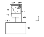
- FIG. 5A is a front view of the ophthalmologic apparatus 1
- FIG. 5B is a side view of the ophthalmologic apparatus 1.
- the ophthalmologic apparatus 1 is provided with a chin rest and a forehead pad for supporting the face of the subject.
- the chin rest and the forehead support correspond to the support portion 440 in FIGS. 5A and 5B.
- Reference numeral 410 denotes a base (also referred to as a base) in which a driving system such as the optical system driving unit 2A and an arithmetic control circuit are stored.
- Reference numeral 415 indicates a pedestal supported so as to be movable with respect to the base 410.
- Reference numeral 420 denotes a housing in which an optical system such as the fundus camera unit 2 and the OCT unit 100 and an imaging unit are stored.
- the housing 420 is provided on the gantry 415.
- Reference numeral 430 denotes a lens housing portion that is provided on the front surface of the housing 420 and accommodates the objective lens 22.
- the optical system driving unit 2A moves the gantry 415 in the left-right direction (x direction), the up-down direction (y direction), and the front-rear direction (z direction), and thereby the fundus camera unit 2 stored in the housing 420 and The OCT unit 100 and the like are moved in these directions. That is, the optical system drive unit 2A moves the inspection optical system 1a together with the housing 420 in each direction of xyz by moving the gantry 415 in each direction of xyz. For this reason, the above-described optical system position acquisition unit 213 may acquire, for example, the current position of the gantry 415 as the current position of the inspection optical system 1a.
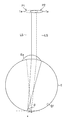
- FIG. 6 is a schematic diagram showing the positional relationship between the eye E to be examined and the examination optical system 1a in a simplified manner when measuring blood flow information.
- a direction perpendicular to the optical axis direction (z direction) of the inspection optical system 1a is from the first position P1 where the inspection optical system 1a is first aligned.
- the gantry 415 is moved by the optical system driving unit 2A so as to be moved to the shifted second position P2.
- the angle ⁇ between the incident direction of the signal light LS and the blood flow vector is smaller than 90 °, and the blood vessel of interest Db blood flow information is obtained.
- the second position P2 is not particularly limited as long as it is shifted from the first position P1 in the direction perpendicular to the z direction.
- the second position P2 is in the x direction, y direction, and xy direction with respect to the first position P1.
- the position may be shifted in either direction.
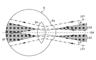
- FIG. 7 is a schematic diagram showing an illumination light beam area and a photographing light beam area of the ophthalmologic apparatus 1 when the inspection optical system 1a is at the first position P1.
- FIG. 8A is a schematic diagram showing an illumination light beam area and a photographing light beam area of the ophthalmologic apparatus 1 when the inspection optical system 1a is moved from the first position P1 to the second position P2.
- FIG. 8B is an enlarged view of a region indicated by reference sign G1 in FIG. 8A
- FIG. 8C is an enlarged view of a region indicated by reference sign G2 in FIG. 8A.
- the illumination light beam area near the pupil of the eye E formed by the illumination optical system 10 and the imaging optical system 30 described above is an illumination light beam LV1 indicated by a one-dot chain line in the drawing.
- the illumination light flux LV2 is formed by a photographing light beam LP indicated by a solid line in the drawing.
- the inspection optical system 1a when the inspection optical system 1a is at the first position P1, that is, when the inspection optical system 1a is first aligned, the optical axis OA of the inspection optical system 1a and the eye E to be examined And the working distance (distance in the z direction) of the inspection optical system 1a with respect to the eye E is an appropriate distance.
- the overlapping area indicated by hatching in the figure
- the illumination light beam area and the imaging light beam area overlap does not cover the cornea of the anterior eye portion Ea and the rear surface of the crystalline lens Ec.
- FIGS. 8A to 8C when the inspection optical system 1a is moved from the first position P1 to the second position P2, the inspection distance is maintained while maintaining the aforementioned working distance.
- the optical axis OA of the optical system 1a is shifted from the cornea center of the eye E to be examined. In this case, since the overlapping area where the illumination light beam area and the photographing light beam area overlap is applied to the cornea of the anterior segment Ea and the rear surface of the crystalline lens Ec, flare is likely to occur.
- the inspection optical system 1a when the inspection optical system 1a is moved from the first position P1 to the second position P2, the alignment of the inspection optical system 1a with respect to the eye E in the z direction (hereinafter referred to as second alignment). ) Automatically.
- FIG. 9 is a functional block diagram illustrating functions of the main control unit 211 after the first alignment. As illustrated in FIG. 9, the main control unit 211 functions as the optical system moving unit 215, the alignment unit 216, and the adjustment control unit 217 when the first alignment of the examination optical system 1 a is completed during blood flow information measurement.
- the optical system moving unit 215 drives the optical system driving unit 2A to move the gantry 415 in a direction perpendicular to the z direction in accordance with the moving operation of the gantry 415 performed by the user at the operation unit 240B after the first alignment is completed. .
- the inspection optical system 1a in the housing 420 is moved from the first position P1 to the second position P2. That is, the optical system moving unit 215 functions as the optical system moving unit of the present invention together with the optical system driving unit 2A.
- the user manually moves the inspection optical system 1a (the gantry 415) from the first position P1 to the second position P2.
- the optical system moving unit 215 is moved. May drive the optical system drive unit 2A to automatically move the inspection optical system 1a to the second position P2.
- the alignment unit 216 functions as the second alignment unit of the present invention together with the optical system driving unit 2A, and controls the second alignment of the inspection optical system 1a.
- the alignment unit 216 first detects a positional difference between the first position P1 and the second position P2 in the x and y directions. (Hereinafter abbreviated as xy position difference).
- the xy position difference includes ⁇ x that is a difference between the x coordinates of the first position P1 and the second position P2, and ⁇ y that is a difference between the respective y coordinates.
- This xy position difference can be acquired, for example, from the position of the inspection optical system 1a acquired by the optical system position acquisition unit 213 described above.
- the xy position difference may be acquired from a position detection sensor capable of detecting the position of the gantry 415 (inspection optical system 1a) such as an encoder provided on the optical system driving unit 2A or the gantry 415.
- the alignment unit 216 refers to the position information table 219 stored in the storage unit 212 based on the acquired position difference, and the z direction of the optical system 1a for inspection with respect to the eye E at the second position P2 ( The alignment position in the optical axis direction is determined.
- the position information table 219 stores the correspondence between the xy position difference ( ⁇ x, ⁇ y) and the alignment position information ⁇ Z indicating the alignment position in the z direction.
- the alignment position information ⁇ Z is a position difference between the z coordinate of the inspection optical system 1a at the first position P1 and the z coordinate of the inspection optical system 1a that is aligned in the z direction at the second position P2.
- the alignment position information ⁇ Z is obtained by performing actual measurement or simulation in advance for each combination pattern of xy position differences ( ⁇ x, ⁇ y).
- the alignment unit 216 refers to the position information table 219 to determine the alignment position in the z direction of the inspection optical system 1a at the second position P2 corresponding to the xy position difference ( ⁇ x, ⁇ y). Can do.
- the alignment unit 216 controls the optical system driving unit 2A based on the determined alignment position to perform the second alignment of the inspection optical system 1a. Thereby, the inspection optical system 1a is moved to the alignment position along the z direction (optical axis direction).
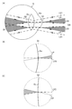
- FIG. 10A is a schematic diagram showing the illumination light beam area and the photographing light beam area of the ophthalmologic apparatus 1 after the completion of the second alignment.
- FIG. 10B is an enlarged view of a region indicated by reference sign G1 in FIG. 10A
- FIG. 10C is an enlarged view of a region indicated by reference sign G2 in FIG.
- an overlapping area (hatched portion in the figure) where the illumination light beam area and the photographing light beam area overlap is an anterior segment.
- Ea's cornea and posterior surface of the lens Ec are not applied.
- the amount of the overlapping area applied to the cornea of the anterior segment Ea and the rear surface of the crystalline lens Ec is reduced as compared with the state before the second alignment shown in FIGS. 8A to 8C.
- movement information ⁇ N indicating a direction and a distance for moving the optical path length changing unit 41 corresponding to the second alignment of the inspection optical system 1 a includes each xy position difference. ( ⁇ x, ⁇ y) [alignment position information ⁇ Z] are stored in association with each other.
- the movement information ⁇ N of the optical path length changing unit 41 that can maintain the optical path length difference constant is represented by the xy position difference ( ⁇ x, ⁇ y).
- Each combination pattern is obtained in advance by measurement or simulation and stored in the position information table 219.
- the movement information ⁇ N of the optical path length changing unit 41 corresponding to the xy position difference ( ⁇ x, ⁇ y) is obtained by referring to the position information table 219.
- the adjustment control unit 217 adjusts the optical path length of the signal light LS by controlling the optical system driving unit 2A and moving the optical path length changing unit 41 according to the second alignment of the inspection optical system 1a.
- the adjustment control unit 217 acquires the xy position difference ( ⁇ x, ⁇ y) or the alignment position information ⁇ Z from the alignment unit 216 when the second alignment of the inspection optical system 1a is performed.
- the adjustment control unit 217 refers to the position information table 219 based on the acquired xy position difference ( ⁇ x, ⁇ y) or the like, and acquires movement information ⁇ N corresponding to the xy position difference ( ⁇ x, ⁇ y) or the like.
- the adjustment control unit 217 controls the optical system driving unit 2A to move the optical path length changing unit 41 based on the acquired movement information ⁇ N.
- the optical path length of the signal light LS is adjusted so that the optical path length difference is maintained constant according to the distance and direction in which the inspection optical system 1a moves in the z direction by the second alignment.
- the optical path length of the reference light LR may be adjusted, or both the optical path lengths of the signal light LS and the reference light LR may be adjusted. Good.
- FIG. 11 is a flowchart showing a flow of measurement processing of blood flow information of the fundus oculi Ef by the ophthalmologic apparatus 1.
- the user After the user turns on the power of the ophthalmologic apparatus 1, the user inputs patient information including the patient ID of the subject and the patient name using the user interface 240 (step S1). This patient information is stored in the storage unit 212.
- the user uses the user interface 240 to select and input the type of examination to be performed on the subject.
- Items of examination type include examination part (fundus center, fundus peripheral part, optic disc, macular etc.), eye to be examined (left eye, right eye, both eyes), image shooting pattern (fundus image only, OCT image only, Both), OCT scan patterns (line scan, cross scan, radial scan, circle scan, three-dimensional scan, etc.) and measurement items (blood flow information, etc.).
- examination part fundus center, fundus peripheral part, optic disc, macular etc.
- eye to be examined left eye, right eye, both eyes
- image shooting pattern fundus image only, OCT image only, Both
- OCT scan patterns line scan, cross scan, radial scan, circle scan, three-dimensional scan, etc.
- measurement items blood flow information, etc.
- the first alignment start instruction may be automatically issued after the inspection type is selected.
- the main control unit 211 starts the imaging (moving image shooting) of the anterior segment Ea by the anterior segment cameras 300A and 300B (step S4).
- captured images (frames) of the anterior segment Ea captured by the anterior segment cameras 300 ⁇ / b> A and 300 ⁇ / b> B are input to the analysis unit 231 via the control unit 210.
- the analysis unit 231 that receives the input of the captured image of the anterior segment Ea from the control unit 210 performs the above-described correction processing, feature point identification processing, and three-dimensional position calculation processing, thereby determining the three-dimensional position of the eye E to be examined.
- the calculation result is output to the main control unit 211 (step S5).
- the optical system position acquisition unit 213 acquires the current position of the inspection optical system 1 a and outputs the acquired current position to the main control unit 211.
- the main control unit 211 receives positional information (appropriate position) of the inspection optical system 1a with respect to the cornea center of the eye E.
- the positional deviation amount and the positional deviation direction in each direction of xyz are obtained.
- the main control unit 211 optically adjusts the position of the inspection optical system 1a with respect to the three-dimensional position of the eye E to be in a predetermined positional relationship based on the positional deviation information.
- the system drive unit 2A is controlled to move the gantry 415 (inspection optical system 1a) (step S6).
- the main control unit 211 composites and displays the alignment index image on the observation image at a predetermined position on the screen of the display unit 240A based on the positional deviation information.
- the user operates the operation unit 240B to move the gantry 415 (inspection optical system 1a) so that the position of the inspection optical system 1a with respect to the three-dimensional position of the eye E to be inspected has a predetermined positional relationship ( Step S6).
- the main control unit 211 functions as an optical system moving unit 215, an alignment unit 216, and an adjustment control unit 217 (see FIG. 9).
- the user performs a moving operation of moving the gantry 415 in the direction perpendicular to the z direction using the operation unit 240B.
- the optical system moving unit 215 controls the optical system driving unit 2A to move the gantry 415 in the vertical direction (step S9).
- the inspection optical system 1a in the housing 420 is moved from the first position P1 to the second position P2.
- the movement of the gantry 415 that is, the movement of the inspection optical system 1a to the second position P2 may be automatically performed by the optical system moving unit 215 after the completion of the first alignment.
- the alignment unit 216 acquires the position of the inspection optical system 1a before and after the movement to the second position P2 from the optical system position acquisition unit 213. To do. Thereby, the alignment unit 216 acquires the xy position difference ( ⁇ x, ⁇ y) between the first position P1 and the second position P2 (step S10).
- the alignment unit 216 refers to the position information table 219 in the storage unit 212 based on the acquired xy position difference ( ⁇ x, ⁇ y), and at the second position P2.
- the alignment position in the z direction of the inspection optical system 1a with respect to the subject eye E is determined.
- the alignment unit 216 controls the optical system driving unit 2A based on the determined alignment position to move the gantry 415 along the z-axis direction (step S11).
- the second alignment in the z direction of the inspection optical system 1a with respect to the eye E is completed by moving the inspection optical system 1a to the alignment position along the z-axis direction (optical axis direction) (step) S12).
- the overlapping area where the illumination light beam area and the photographing light beam area overlap is an anterior eye. Since the cornea of the portion Ea and the rear surface of the crystalline lens Ec are not applied or the amount of the reduction is reduced, the occurrence of flare can be reduced.
- the adjustment control unit 217 refers to the position information table 219 based on the xy position difference ( ⁇ x, ⁇ y) acquired from the alignment unit 216 and the like, and the like.
- the movement information ⁇ N corresponding to is acquired.
- the adjustment control unit 217 controls the optical system driving unit 2A to move the optical path length changing unit 41 based on the acquired movement information ⁇ N.
- the optical path length of the signal light LS is adjusted so that the optical path length difference between the signal light LS and the reference light LR is maintained constant before and after the second alignment (step S13).
- the depth of the fundus oculi Ef from which the OCT image is obtained is prevented from changing before and after the second alignment.
- the user issues a blood flow information measurement start instruction using the operation unit 240B.
- the blood flow information measurement start instruction may be automatically performed after the completion of the second alignment and the optical path length adjustment.
- the ophthalmologic apparatus 1 Upon receiving this blood flow information measurement start instruction, the ophthalmologic apparatus 1 performs the first and second scans described above with respect to the blood vessel Db of interest (see FIG. 3).
- the OCT image forming unit 221 forms the first OCT image and the second OCT image
- the phase image forming unit 222 forms a phase image.
- the blood flow information generation unit 233 generates blood flow information related to the target blood vessel Db.
- step S14 This completes the measurement of blood flow information related to the target blood vessel Db (step S14).
- the measurement result of the blood flow information regarding the target blood vessel Db is stored in the storage unit 212 in association with the above-described patient information.
- the alignment position in the z direction of the inspection optical system 1a at the second position P2 can be determined simply by referring to the position information table 219. As a result, the alignment position can be determined easily and at a higher speed than in the prior art.
- FIG. 12 is a flowchart showing a flow of blood flow information measurement processing of the fundus oculi Ef in a comparative example employing the method described in Patent Document 3.
- the processing from step S1 to step S9 is basically the same as that of the present embodiment, and the description thereof is omitted here.
- step S9 When the inspection optical system 1a is moved from the first position P1 to the second position P2 along with the movement of the gantry 415 in step S9, in the comparative example, in front of the eye E to be examined photographed by the anterior eye cameras 300A and 300B.
- the captured image of the eye part Ea is analyzed to detect the amount of misalignment in the xy direction of the second position with respect to the first position P1 (step S10A).
- the alignment position in the z direction of the inspection optical system 1a is calculated based on the detected misalignment amount (step S10B). Since the subsequent processing is basically the same as that of the present embodiment, a detailed description thereof will be omitted.
- the ophthalmologic apparatus 1 of the present embodiment by directly detecting the movement of the gantry 415 (inspection optical system 1a), without performing image analysis as in the comparative example, The xy position difference ( ⁇ x, ⁇ y) between the first position P1 and the second position P2 can be easily detected. Further, in the ophthalmologic apparatus 1 according to the present embodiment, the alignment position in the z direction can be easily determined simply by referring to the position information table 219, so that the process as in step S10B of the comparative example is not necessary. As a result, in the ophthalmologic apparatus 1 of the present embodiment, the second alignment can be performed at a low cost and in a short time without using a high-performance arithmetic processing device.
- the second position P2 of the inspection optical system 1a at the time of blood flow information measurement has been described by taking as an example a position shifted in the vertical direction from the first position P1 in the z direction (see FIG. 6).
- the second position P2 is not particularly limited as long as it is deviated from the first position P1 in at least a direction perpendicular to the z direction, and is deviated in both the direction perpendicular to the z direction and the z direction. Also good.
- the second position P2 may be a position shifted in any of the xz direction, the yz direction, and the xyz direction with respect to the first position P1.
- the correspondence relationship between the position information ⁇ Z and the movement information ⁇ N is stored.
- the position information table 219 is stored in the storage unit 212 as information indicating the correspondence between the position difference between the first position P1 and the second position P2 and the alignment position in the z direction.
- an arithmetic expression representing the above-described correspondence may be stored in the storage unit 212.
- the inspection optical system 1a is moved with respect to the eye E by moving the gantry 415.
- the method for moving the inspection optical system 1a with respect to the eye E is particularly limited. Instead, other known methods may be used.
- the three-dimensional position of the eye E is acquired by analyzing the captured images taken by the anterior eye cameras 300A and 300B by the analysis unit 231, but the three-dimensional position of the eye E is acquired.
- Various known methods may be adopted as the method of performing.
- the ophthalmologic apparatus 1 that measures blood flow information of the fundus oculi Ef that is an observation site of the eye E by moving the inspection optical system 1a from the first position P1 to the second position P2 has been described.
- the present invention can also be applied to an ophthalmologic apparatus that performs various measurements of the observation site of the eye E at a position where the inspection optical system 1a is moved in the direction perpendicular to at least the z direction from the first position P1.
- this ophthalmologic apparatus uses a scanning laser ophthalmoscope (Scanning Laser Ophthalmoscope, SLO) that obtains an image of the fundus by laser scanning using a confocal optical system, and slit light.
- SLO scanning Laser Ophthalmoscope
- a slit lamp that obtains an image by cutting out a light slice of the cornea
- an eye refraction examination device refractometer, keratometer
- corneal characteristics corneal thickness, cell distribution, etc.
- specular microscope that obtains and a wavefront analyzer that obtains aberration information of the eye to be examined using a Hartmann-Shack sensor.
- SYMBOLS 1 Ophthalmology apparatus, 1a Examination optical system, 2 Fundus camera unit, 2A optical system drive part, 30 imaging optical system, 41 Optical path length change part, 100 OCT unit, 100a interference optical system, 115 Image sensor, 210 Control part, 211 Main control unit, 212 storage unit, 213 optical system position acquisition unit, 215 optical system moving unit, 216 alignment unit, 217 adjustment control unit, 219 position information table, 220 image forming unit, 231 analysis unit, 232 blood vessel region specifying unit, 233 Blood flow information generation unit, 240 user interface, 240B operation unit, 300, 300A, 300B anterior eye camera 300, 415 mount, 420 housing
Landscapes
- Health & Medical Sciences (AREA)
- Life Sciences & Earth Sciences (AREA)
- Medical Informatics (AREA)
- Biophysics (AREA)
- Ophthalmology & Optometry (AREA)
- Engineering & Computer Science (AREA)
- Biomedical Technology (AREA)
- Heart & Thoracic Surgery (AREA)
- Physics & Mathematics (AREA)
- Molecular Biology (AREA)
- Surgery (AREA)
- Animal Behavior & Ethology (AREA)
- General Health & Medical Sciences (AREA)
- Public Health (AREA)
- Veterinary Medicine (AREA)
- Hematology (AREA)
- Nuclear Medicine, Radiotherapy & Molecular Imaging (AREA)
- Radiology & Medical Imaging (AREA)
- Eye Examination Apparatus (AREA)
Priority Applications (2)
| Application Number | Priority Date | Filing Date | Title |
|---|---|---|---|
| US16/085,642 US10918277B2 (en) | 2016-03-18 | 2017-01-13 | Ophthalmic device |
| EP17766026.3A EP3430975B1 (en) | 2016-03-18 | 2017-01-13 | Ophthalmic device |
Applications Claiming Priority (2)
| Application Number | Priority Date | Filing Date | Title |
|---|---|---|---|
| JP2016055560A JP6624641B2 (ja) | 2016-03-18 | 2016-03-18 | 眼科装置 |
| JP2016-055560 | 2016-03-18 |
Publications (1)
| Publication Number | Publication Date |
|---|---|
| WO2017159018A1 true WO2017159018A1 (ja) | 2017-09-21 |
Family
ID=59850451
Family Applications (1)
| Application Number | Title | Priority Date | Filing Date |
|---|---|---|---|
| PCT/JP2017/001113 Ceased WO2017159018A1 (ja) | 2016-03-18 | 2017-01-13 | 眼科装置 |
Country Status (4)
| Country | Link |
|---|---|
| US (1) | US10918277B2 (OSRAM) |
| EP (1) | EP3430975B1 (OSRAM) |
| JP (1) | JP6624641B2 (OSRAM) |
| WO (1) | WO2017159018A1 (OSRAM) |
Cited By (1)
| Publication number | Priority date | Publication date | Assignee | Title |
|---|---|---|---|---|
| CN111787843A (zh) * | 2018-01-31 | 2020-10-16 | 株式会社拓普康 | 血流测量装置 |
Families Citing this family (6)
| Publication number | Priority date | Publication date | Assignee | Title |
|---|---|---|---|---|
| JP6991075B2 (ja) * | 2018-01-31 | 2022-01-12 | 株式会社トプコン | 血流計測装置 |
| JP7096116B2 (ja) * | 2018-09-26 | 2022-07-05 | 株式会社トプコン | 血流計測装置 |
| US20210059520A1 (en) * | 2019-09-03 | 2021-03-04 | Johnson & Johnson Vision Care, Inc. | Ophthalmic systems and methods for direct retinal stimuli with local retinal angle of incidence control |
| US12076083B2 (en) * | 2019-11-06 | 2024-09-03 | Lightx Innovations Inc. | Automated slit lamp system and method of examining an eye using same |
| EP3889889A1 (en) * | 2020-03-30 | 2021-10-06 | Optos PLC | Ocular image data processing |
| WO2025182271A1 (ja) * | 2024-02-26 | 2025-09-04 | 株式会社トプコン | 眼科装置、眼科装置を制御する方法、プログラム、及び記録媒体 |
Citations (6)
| Publication number | Priority date | Publication date | Assignee | Title |
|---|---|---|---|---|
| JP2012196324A (ja) | 2011-03-22 | 2012-10-18 | Nidek Co Ltd | 眼底撮影装置 |
| JP2013208158A (ja) | 2012-03-30 | 2013-10-10 | Topcon Corp | 画像表示装置、画像表示方法、及びプログラム |
| JP2013244363A (ja) * | 2012-05-29 | 2013-12-09 | Nidek Co Ltd | 眼底撮影装置 |
| JP2013248376A (ja) | 2012-05-01 | 2013-12-12 | Topcon Corp | 眼科装置 |
| JP2014113385A (ja) * | 2012-12-11 | 2014-06-26 | Topcon Corp | 眼科装置 |
| JP2015150074A (ja) * | 2014-02-12 | 2015-08-24 | キヤノン株式会社 | 眼科撮影装置、その制御方法、及びプログラム |
Family Cites Families (4)
| Publication number | Priority date | Publication date | Assignee | Title |
|---|---|---|---|---|
| US6945650B2 (en) * | 2001-11-06 | 2005-09-20 | Reichert, Inc. | Alignment system for hand-held ophthalmic device |
| JP4408640B2 (ja) * | 2003-03-17 | 2010-02-03 | 興和株式会社 | 眼科測定装置 |
| JP6009935B2 (ja) * | 2012-12-26 | 2016-10-19 | 株式会社トプコン | 眼科装置 |
| JP6349878B2 (ja) | 2014-03-31 | 2018-07-04 | 株式会社ニデック | 眼科撮影装置、眼科撮影方法、及び眼科撮影プログラム |
-
2016
- 2016-03-18 JP JP2016055560A patent/JP6624641B2/ja active Active
-
2017
- 2017-01-13 WO PCT/JP2017/001113 patent/WO2017159018A1/ja not_active Ceased
- 2017-01-13 US US16/085,642 patent/US10918277B2/en active Active
- 2017-01-13 EP EP17766026.3A patent/EP3430975B1/en active Active
Patent Citations (6)
| Publication number | Priority date | Publication date | Assignee | Title |
|---|---|---|---|---|
| JP2012196324A (ja) | 2011-03-22 | 2012-10-18 | Nidek Co Ltd | 眼底撮影装置 |
| JP2013208158A (ja) | 2012-03-30 | 2013-10-10 | Topcon Corp | 画像表示装置、画像表示方法、及びプログラム |
| JP2013248376A (ja) | 2012-05-01 | 2013-12-12 | Topcon Corp | 眼科装置 |
| JP2013244363A (ja) * | 2012-05-29 | 2013-12-09 | Nidek Co Ltd | 眼底撮影装置 |
| JP2014113385A (ja) * | 2012-12-11 | 2014-06-26 | Topcon Corp | 眼科装置 |
| JP2015150074A (ja) * | 2014-02-12 | 2015-08-24 | キヤノン株式会社 | 眼科撮影装置、その制御方法、及びプログラム |
Non-Patent Citations (1)
| Title |
|---|
| See also references of EP3430975A4 |
Cited By (3)
| Publication number | Priority date | Publication date | Assignee | Title |
|---|---|---|---|---|
| CN111787843A (zh) * | 2018-01-31 | 2020-10-16 | 株式会社拓普康 | 血流测量装置 |
| CN111787843B (zh) * | 2018-01-31 | 2023-07-21 | 株式会社拓普康 | 血流测量装置 |
| US11911108B2 (en) | 2018-01-31 | 2024-02-27 | Topcon Corporation | Blood flow measurement apparatus |
Also Published As
| Publication number | Publication date |
|---|---|
| JP2017169602A (ja) | 2017-09-28 |
| US20200288976A1 (en) | 2020-09-17 |
| US10918277B2 (en) | 2021-02-16 |
| JP6624641B2 (ja) | 2019-12-25 |
| EP3430975B1 (en) | 2021-11-24 |
| EP3430975A1 (en) | 2019-01-23 |
| EP3430975A4 (en) | 2019-04-03 |
Similar Documents
| Publication | Publication Date | Title |
|---|---|---|
| JP6009935B2 (ja) | 眼科装置 | |
| JP6560423B2 (ja) | 眼科装置 | |
| JP6112846B2 (ja) | 眼科装置 | |
| JP6412707B2 (ja) | 眼科装置 | |
| JP6566541B2 (ja) | 眼科装置 | |
| JP6498398B2 (ja) | 眼科装置 | |
| JP6624641B2 (ja) | 眼科装置 | |
| JP4823693B2 (ja) | 光画像計測装置 | |
| JP6388440B2 (ja) | 眼科装置 | |
| JP2013208394A (ja) | 光干渉断層撮影装置及びその方法 | |
| JP6407631B2 (ja) | 眼科装置 | |
| JP6809926B2 (ja) | 眼科装置 | |
| JP2018051340A (ja) | 眼科装置 | |
| JP6310589B2 (ja) | 眼科装置 | |
| JP7231366B2 (ja) | 眼科装置および眼科装置の制御方法 | |
| JP6959158B2 (ja) | 眼科装置 |
Legal Events
| Date | Code | Title | Description |
|---|---|---|---|
| NENP | Non-entry into the national phase |
Ref country code: DE |
|
| WWE | Wipo information: entry into national phase |
Ref document number: 2017766026 Country of ref document: EP |
|
| ENP | Entry into the national phase |
Ref document number: 2017766026 Country of ref document: EP Effective date: 20181018 |
|
| 121 | Ep: the epo has been informed by wipo that ep was designated in this application |
Ref document number: 17766026 Country of ref document: EP Kind code of ref document: A1 |