WO2017158931A1 - 有機エレクトロルミネッセンス素子の発光パターン形成方法 - Google Patents
有機エレクトロルミネッセンス素子の発光パターン形成方法 Download PDFInfo
- Publication number
- WO2017158931A1 WO2017158931A1 PCT/JP2016/084448 JP2016084448W WO2017158931A1 WO 2017158931 A1 WO2017158931 A1 WO 2017158931A1 JP 2016084448 W JP2016084448 W JP 2016084448W WO 2017158931 A1 WO2017158931 A1 WO 2017158931A1
- Authority
- WO
- WIPO (PCT)
- Prior art keywords
- organic
- mask
- light
- sheet
- light irradiation
- Prior art date
- Legal status (The legal status is an assumption and is not a legal conclusion. Google has not performed a legal analysis and makes no representation as to the accuracy of the status listed.)
- Ceased
Links
Images









Classifications
-
- H—ELECTRICITY
- H10—SEMICONDUCTOR DEVICES; ELECTRIC SOLID-STATE DEVICES NOT OTHERWISE PROVIDED FOR
- H10K—ORGANIC ELECTRIC SOLID-STATE DEVICES
- H10K71/00—Manufacture or treatment specially adapted for the organic devices covered by this subclass
- H10K71/10—Deposition of organic active material
- H10K71/16—Deposition of organic active material using physical vapour deposition [PVD], e.g. vacuum deposition or sputtering
- H10K71/166—Deposition of organic active material using physical vapour deposition [PVD], e.g. vacuum deposition or sputtering using selective deposition, e.g. using a mask
-
- H—ELECTRICITY
- H05—ELECTRIC TECHNIQUES NOT OTHERWISE PROVIDED FOR
- H05B—ELECTRIC HEATING; ELECTRIC LIGHT SOURCES NOT OTHERWISE PROVIDED FOR; CIRCUIT ARRANGEMENTS FOR ELECTRIC LIGHT SOURCES, IN GENERAL
- H05B33/00—Electroluminescent light sources
- H05B33/10—Apparatus or processes specially adapted to the manufacture of electroluminescent light sources
Definitions
- the present invention relates to a method for forming a light emission pattern of an organic electroluminescence element using a pattern-forming light irradiation device having a cooling function. More specifically, the present invention suppresses thermal deformation of the mask during pattern formation and thermal damage to the organic electroluminescence element by the cooling function, and the organic electroluminescence capable of forming a light emitting pattern with high productivity and high dimensional accuracy.
- the present invention relates to a light emitting pattern forming method for an element.
- organic light emitting panels are attracting attention as thin light emitting devices.
- an organic light-emitting element (hereinafter also referred to as “organic EL element”) using electroluminescence (EL) of an organic material is a thin film type that can emit light at a low voltage of about several volts to several tens of volts.
- EL electroluminescence
- This is a complete solid panel, can obtain high brightness with low power, has excellent features such as excellent visibility, response speed, lifetime, power consumption, etc., and can be reduced in thickness and weight.
- attention has been focused on various displays using organic EL elements as panels, their backlights, display boards such as signboards and emergency lights, and surface light emitters such as illumination light sources.
- a light-emitting layer made of an organic material or the like is disposed between two electrodes, and emitted light generated in the light-emitting layer passes through the electrode and is extracted outside.
- at least one of the two electrodes is configured as a transparent electrode, and emitted light is extracted from the transparent electrode side.
- the organic functional layer of the manufactured organic EL element is irradiated with an active energy ray such as ultraviolet rays to deactivate the light emission function of the irradiated portion.
- an active energy ray such as ultraviolet rays
- a manufacturing method of a light emitting display element in which a light emitting region is formed and a light emitting pattern having the non-light emitting region is formed is disclosed (for example, refer to Patent Document 1).
- Patent Document 1 a method of forming a light emission pattern by ultraviolet irradiation using a mask is described, but no consideration is given to a method of cooling an organic EL element or a mask. Absent.
- Patent Document 1 is a method of performing patterning in a so-called batch method in which each individual organic EL element is irradiated with light, and in this method, the productivity is low and the light emitting pattern is provided.
- this method meets the demands for high productivity and the like that can form light emission patterns on a plurality of organic EL elements at once.
- an organic EL element is manufactured by a roll-to-roll method or a wet coating method
- a plurality of organic EL elements are formed on the substrate, and then the substrate is cut by a predetermined length.
- a plurality of organic EL elements are patterned at once by irradiating light to a plurality of organic EL elements in a state of a sheet having organic EL elements cut to a predetermined length. It is possible to improve production efficiency.
- the organic EL element itself is more vulnerable to heat because the structure of the organic EL element is more complex than that of a photoresist used in the manufacture of circuits such as semiconductors and liquid crystal display devices.
- the film quality of the organic material changes due to heat, resulting in a change in luminous efficiency, chromaticity, and a reduction in device lifetime.
- the color balance is difficult to maintain, so the allowable width is narrow and it is more susceptible to heat, and as a result, the color balance is likely to be lost.
- problems specific to organic EL elements are problems specific to organic EL elements.
- the glass substrate of the liquid crystal display (LCD), which is the object to be illuminated is irradiated with near-field light, the glass substrate is transported to the light irradiation table, and cooling of the glass substrate is started.
- a method of cooling the glass substrate until it is moved to the irradiation position and irradiated with light, and the light irradiation is completed and discharged and conveyed is disclosed (for example, see Patent Document 2).
- Patent Document 2 it is a method for cooling a crow substrate, a method for cooling a mask used for patterning an organic EL element, preventing thermal deformation at the time of light irradiation, etc., and forming a highly accurate light-emitting pattern.
- no reference is made to a method for improving productivity by collectively irradiating light to a plurality of irradiated bodies (for example, organic EL elements).
- Photomasks for near light irradiation are always placed under the light source unit, and it is assumed that air is always blown.
- the mask cooling air requires a large amount of air of 1000 L / min or more.
- the running cost for air blowing is at a level that cannot be ignored, and it is desirable to stop the blowing except during light irradiation.
- Patent Document 3 does not pose any such issues or considerations.
- no reference is made to a method for improving productivity by collectively irradiating light to a plurality of irradiated bodies (for example, organic EL elements).
- the present invention has been made in view of the above-described problems and situations, and a solution to the problem is to provide an efficient mask cooling function, thermal deformation of the mask during pattern formation, and thermal damage to a plurality of organic EL elements. It is an object to provide a light emitting pattern forming method for an organic EL element capable of forming a light emitting pattern with excellent productivity and high dimensional accuracy.
- the present inventor put an organic EL sheet on which a plurality of organic EL elements are arranged on a light irradiation object mounting table having a cooling function. Then, the mask is placed at a predetermined position on the organic EL sheet by alignment, and then the organic EL sheet is irradiated with light through the mask while cooling the mask by spraying a fluid onto the surface of the mask.
- the present inventors have found that the above problem can be solved by a method of forming a light emission pattern, and stopping the spraying of a cooling fluid to the mask surface after completion of light irradiation, thereby forming the light emission pattern of the organic EL element. .
- a method for forming a light emission pattern of an organic electroluminescence element wherein the organic electroluminescence element is irradiated with light through a mask to form a light emission pattern
- a method for forming a light emitting pattern of an organic electroluminescent element wherein a light emitting pattern is formed on the organic electroluminescent element through the following steps 1 to 5.
- Step 1 Step of placing a sheet-like organic electroluminescence element sheet on which a plurality of organic electroluminescence elements are formed at a predetermined position of a light irradiation object mounting table having a cooling function
- Step 2 The mask Are arranged and adhered to a predetermined position of the organic electroluminescence element sheet by alignment using an alignment mark.
- Step 3 A step of spraying a fluid onto the surface of the mask.
- Step 4 The organic electroluminescence is passed through the mask.
- Step 5 Stopping spraying of the fluid onto the mask surface after completion of the light irradiation.
- the step 1 and the step 2 are performed at a position away from the light irradiation position of the step 4, and the light irradiation position is set in a state where the organic electroluminescence element sheet and the mask are mounted on the light irradiation object mounting table.
- the light irradiation in said step 4 performs light irradiation collectively through the said mask with respect to the total number of the organic electroluminescent elements arrange
- the light irradiation in said step 4 divides
- the present invention has an efficient mask cooling function, suppresses thermal deformation of the mask during pattern formation and thermal damage to the plurality of organic EL elements, and pattern formation on a plurality of organic EL elements at once.
- the light emitting pattern forming method of the organic EL element of the present invention is a method of patterning by irradiating the organic EL element with light, for example, irradiating with ultraviolet rays to form a non-light emitting portion, and this method includes a plurality of organic EL elements. This is an optimal method when patterning is performed by irradiating light of high irradiance on a large organic EL sheet having a planar arrangement.
- the basic step is to place the organic EL sheet and mask on a light irradiation object mounting table equipped with a cooling function, and blow the airflow, for example, air onto the mask surface to sufficiently cool the organic EL sheet and mask in advance. In this state, light is irradiated to form a light emission pattern, and then the air flow is stopped.
- the organic EL sheet and the mask are placed in a predetermined position on a light irradiation object mounting table having a cooling function and cooled in advance, and mask cooling air is blown onto the mask before light irradiation.
- Light irradiation can be started in a state where the organic EL sheet and the mask are sufficiently cooled, and accurate patterning can be performed while suppressing thermal deformation of the mask and thermal damage of the organic EL element.
- the running cost of air can be reduced by performing the air blowing operation on the mask only when necessary.
- FIG. 1 is an overall configuration diagram showing an example of a light emission pattern forming apparatus applicable to the present invention.
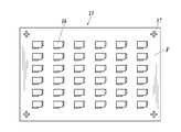
- Schematic sectional view showing an example of the configuration of an organic EL element applicable to the present invention Schematic plan view showing an example of the configuration of an organic EL sheet in which a plurality of organic EL elements are arranged
- Schematic plan view showing an example of the configuration of a mask used for forming a light emitting pattern Schematic which shows an example of a structure of the cooling pipe which a to-be-irradiated body mounting base comprises The perspective view which mounted the organic EL sheet on the to-be-irradiated body mounting stand which has a cooling function
- Schematic which shows the structure of the light source part in the preparatory process of step 1, a mask alignment apparatus, and a to-be-irradiated body mounting base.
- Schematic which shows an example of the method of mounting an organic electroluminescent sheet on a to-be-irradiated body mounting stand
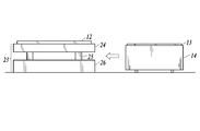
- Schematic which shows an example which moves a to-be-irradiated body mounting stand to the position of a mask alignment apparatus
- Schematic cross-sectional view showing an example of a method for bringing the organic EL sheet on the irradiated object mounting table and the mask on the mask alignment apparatus into close contact at a predetermined position in Step 2
- Schematic cross-sectional view showing another example of the method for bringing the organic EL sheet on the irradiated object mounting table and the mask on the mask alignment apparatus into close contact at a predetermined position in Step 2
- Schematic sectional view showing the method of moving the irradiated object mounting table to the light irradiation position
- Schematic sectional view showing spraying of cooling fluid on the mask surface before light irradiation in Step 3
- Schematic sectional view showing step 4 of forming a light emission pattern by ultraviolet irradiation
- a method for forming a light emission pattern of an organic electroluminescence element according to the present invention is a method for forming a light emission pattern by irradiating an organic electroluminescence element with a light through a mask. A light emission pattern is formed on the electroluminescence element.
- the flow of starting light irradiation in step 4 according to the present invention after the fluid flow rate in step 3 according to the present invention is 1000 L / min or more. It is preferable that the mask and the like can be reliably cooled before light irradiation, and the light emission pattern can be stably formed with high accuracy.
- Step 3 is preferably a flow in which a fluid is sprayed onto the mask surface before light irradiation in that the organic EL sheet and the mask can be sufficiently cooled before the light irradiation is started.
- a method for forming a light emitting pattern a method of irradiating light to all the organic EL elements at once through a mask with respect to the total number of organic EL elements arranged on the organic EL sheet is It is preferable in that the formation time can be shortened and high productivity can be achieved.
- an organic EL sheet is divided into a plurality of regions, and light is irradiated multiple times through a mask for each of the divided regions. Generation of an excessive amount of heat due to irradiation can be suppressed, mask deformation and the like can be prevented, and a highly accurate light emission pattern can be formed.
- a method for forming a light emission pattern of an organic EL element of the present invention is a method for forming a light emission pattern of an organic EL element in which a light emission pattern is formed by irradiating the organic EL element with light through a mask. A light emission pattern is formed on the organic EL element through steps 1 to 5 described below.
- Step 1 Place a sheet-like organic EL sheet on which a plurality of organic EL elements are formed at a predetermined position of a light irradiation object mounting table having a cooling function.
- Step 2 Align the mask with the mask.
- Step 3 Arrangement and adhesion of the organic EL sheet at a predetermined position by alignment using marks
- Step 3 Step of spraying fluid onto the surface of the mask
- Step 4 Light irradiation of the organic EL sheet through the mask
- Step 5 Step of stopping spraying of the fluid onto the mask surface after completion of the light irradiation.
- the light emitting pattern forming apparatus applied to the light emitting pattern forming method of the organic EL element of the present invention mainly includes an irradiation light generating unit for irradiating ultraviolet rays or the like for forming a pattern by reducing the light emitting function of the organic EL element.
- a light source unit configured by a casing that reflects and guides ultraviolet rays emitted from the irradiation light generation unit, a mask irradiated with ultraviolet rays, and an organic EL sheet for forming a light emission pattern are placed below the light source unit. It is comprised from a to-be-irradiated body mounting stand.
- a pair of fluid generators arranged to blow a mask cooling fluid, for example, air in parallel with the mask and toward the center of the mask through the gap between the mask and the housing is provided.
- a mask cooling fluid for example, air in parallel with the mask and toward the center of the mask through the gap between the mask and the housing
- FIG. 1 is an overall configuration diagram showing an example of a light emission pattern forming apparatus applicable to the present invention.
- the light emission pattern forming apparatus (1) shown in FIG. 1 mainly includes a light source unit (2) including an ultraviolet ray generation unit (8), a light irradiated object mounting table (14), a fluid generation unit (10), and the like. It is made up of.
- LEDs (5) having a light emission wavelength of 365 nm or 385 nm are arranged in parallel on the LED substrate (4) as a light source for emitting ultraviolet rays on the LED substrate (4).
- the emitted divergent light is shaped into a light beam having a predetermined divergence angle by the lens array (7), and the light emission pattern is passed through the casing (9) that reflects and guides the light, and through the mask (12) positioned below the casing (9).
- Light is emitted to the organic EL sheet (13) held on the light irradiation object mounting table (14).
- the ultraviolet light emitted from the lens array (7) is confined in the housing (9) whose inner surface is a reflection surface, prevents the light amount from decreasing, and is irradiated to the mask (12) with a uniform light amount.
- the distance (WD) between the lower end of the housing (9) and the mask (12) should be as narrow as possible, preferably about 5 mm. If it is this space
- the LED (5) performs intermittent light irradiation by controlling the irradiation output and irradiation time during lighting, extinguishing and lighting by a controller (not shown).
- the lens array (7) is used as the divergence angle shaping means, but a condensing mirror such as a compound parabolic concentrator may be used.
- a heat radiating plate (3) for releasing heat generated by the light emission of the LED to the outside is provided on the upper part of the ultraviolet ray generating part (8).
- the organic EL sheet (13) is placed on the irradiated object placing base (14), and the mask (12) is adjusted to a predetermined relative position with the organic EL sheet (13) and placed on the organic EL sheet (13). Placed. At this time, it is preferable to apply a method of adsorbing and fixing the organic EL sheet (13) to the irradiated body mounting table (14).
- the organic EL sheet (13) is, for example, a resin film containing polyethylene terephthalate (abbreviation: PET) or polyethylene naphthalate (abbreviation: PEN) as a resin component
- PET polyethylene terephthalate
- PEN polyethylene naphthalate
- the organic EL sheet (13) is preferable in that the entire surface of the organic EL sheet (13) is adhering and fixed to the irradiated body mounting table (14) to fix the light irradiation blur at the time of forming the light emission pattern with good flatness. It is.
- the light irradiated body mounting table (14) has a function of cooling the organic EL sheet (13) by a water cooling method.
- a means for cooling the heat pipe generated in the mask (12) or the organic EL sheet (13) by ultraviolet irradiation with cooling water or the like is provided inside the irradiated object mounting table (14). It is preferable.
- a mask cooling fluid (11), for example, air is parallel to the mask (12), and It is characterized by comprising a pair of fluid generators (10) arranged so as to be sprayed in the central direction of the mask (12).
- the mask cooling fluid (11) sprayed in the central direction in parallel with the mask (12) uniformly cools the mask (12) surface and joins at the central portion.
- the air flow rises to the upper part of the housing (9), reaches the ultraviolet light emitting part (8), and further descends along the side surface of the housing (9) to convect.
- air circulation (convection) inside the housing (9) is promoted to cool the air whose temperature has risen inside the housing (9), and the housing (9) can also be efficiently cooled. it can.
- the blown air absorbs heat, circulates inside the housing (9), and is exhausted from the side surface adjacent to the surface provided with the air flow generation unit (10).
- a light source that emits ultraviolet light is attached to the ultraviolet light emitting unit.
- the light source is not particularly limited as long as it is a light source that emits desired ultraviolet light.
- the ultraviolet ray referred to in the present invention refers to an electromagnetic wave having a wavelength longer than that of X-rays and shorter than the shortest wavelength of visible light.
- the wavelength region is in the range of 1 to 400 nm, preferably As the wavelength of irradiation light to be applied, it is preferable to use irradiation light having a maximum wavelength at 355 nm, 365 nm, 380 nm, 405 nm, or the like.
- Examples of light sources that emit ultraviolet light that can be applied to the present invention include LEDs, ultra-high pressure mercury lamps, high-pressure mercury lamps, low-pressure mercury lamps, carbon arcs, metal halide lamps, xenon arc lamps, carbon arc lamps, excimer lamps, and UV light lasers. Can be used.
- UV-LED an LED that emits ultraviolet rays as illustrated in FIG. 1
- UV-LED an LED that emits ultraviolet rays as illustrated in FIG. 1
- the UV-LED is an LED having a wavelength of 250 to 400 nm, and the UV-LED is further a UVA-LED having an emission wavelength in the range of 350 to 400 nm, and an UVB ⁇ having an emission wavelength in the range of 280 to 350 nm.
- UVC-LEDs having an emission wavelength in the range of 250 to 280 nm, which are appropriately selected and used depending on the respective applications.
- nitride semiconductors such as GaN, InGaN, AlGaN and the like can be mentioned.
- a plurality of LEDs (5) are arranged in a planar shape on the LED substrate (4) to form a light emitting part.
- a lens array (7) is provided via a lens array support (6), and diverging light emitted from the LED (5) is converted into a light flux having a predetermined spread angle. Shape it.
- the irradiation amount of ultraviolet rays depends on the size of the organic EL sheet, but can be irradiated with an integrated light amount of 200 to 5000 J / cm 2 . Further, it is preferable that the irradiation time of one pulse of ultraviolet light in the intermittent irradiation is in the range of 1 to 300 seconds.
- the casing (9) that reflects and guides light has a function of preventing a decrease in the amount of ultraviolet (L) light emitted from the ultraviolet light emitting section (8) and irradiating the mask with a uniform amount of light. Therefore, it is preferable that the inner surface is coated with a reflective material.
- a reflective material a metal material can be used because it has heat resistance and durability.
- aluminum can be preferably used because it is lightweight.
- the ultraviolet light emitting part (8) is attached to the upper part of the housing (9) and has a gap (WD) with the mask (12) at the lower end, its height and bottom area are particularly limited. It can set according to the magnitude
- the bottom surface is preferably larger than the pattern to be produced.
- the organic EL sheet (13) is large and particularly effective for cooling during ultraviolet irradiation when the amount of irradiation light is large, for example, an organic EL sheet having a size of 0.1 to 7 m 2 is used. It is effective for manufacturing.
- productivity can be increased by manufacturing a plurality of organic EL elements by a single ultraviolet irradiation process.
- the height of the housing can be adjusted as appropriate based on variations in the amount of ultraviolet light and the amount of irradiation light.
- the gap between the housing and the mask 5.0mm [Fluid generator]
- the fluid generator (10) passes the gap (WD) between the mask (12) and the housing (9) at a position facing the upper surface of the mask (12).
- a cooling fluid 11, also simply referred to as “fluid” hereinafter, for example, air is arranged to be blown in parallel to the mask (12) and toward the center of the mask (12).
- a pair of fluid generators (10) arranged at both ends are positioned on the upper surface of the mask (12), and the fluid (11) sprayed is sprayed by spraying fluid parallel to the mask (12). Instead, it proceeds on the mask (12) and joins at the center of the mask (12).
- Spraying in parallel means spraying at an angle within ⁇ 2 degrees with respect to the plane of the mask (12).
- the cooling of the mask (12) becomes insufficient.
- the air blown to the mask (12) is turbulent, causing uneven cooling of the mask (12) and joining at the center.
- the generated air generates turbulent flow inside the housing (9), and the above-described convection does not occur and cooling is not efficient.
- the fluid (11) sprayed on the mask (12) joins at the center of the mask (12).
- the mask (12) and the housing (9) can be cooled uniformly.
- the two fluid generating parts (10) are arranged in parallel to the opposing positions on the upper surface of the mask (12).
- the side surface of the casing (9) on the side to be sprayed is also parallel.
- the distance (d) between the housing (9) and the fluid generator (10) is not particularly limited as long as air is efficiently blown onto the mask (12), but is preferably within a range of 10 to 200 mm. More preferably, it is in the range of 50 to 100 mm.
- the length of the fluid generating part (10) is preferably the same as or larger than the width of the casing (9) on the blowing side.
- the fluid (11) sprayed from the fluid generator (10) is sprayed to the mask (12) through the gap (WD) between the mask (12) and the housing (9).
- This gap (WD) functions as an air inlet / outlet for the inside of the housing, but the sprayed fluid (11), for example, air efficiently circulates in the housing (9). Also affects.
- the gap (WD) is preferably in the range of 2 to 20 mm, and more preferably in the range of 3 to 10 mm. If the gap is within 20 mm, the fluid is efficiently circulated in the housing (9), and if it is 2 mm or more, a sufficient air volume for cooling can be obtained.
- the pair of fluid generating parts (10) is arranged at symmetrical positions with respect to the central part of the housing (9) and the mask (12).
- a lower part of the mask (12) is provided with a light irradiation object mounting table (14) having a water cooling tube, and cools the mask through the organic EL sheet. It is desirable.
- the fluid generator (10) is provided with a slit-like or nozzle-like spraying portion. It is preferable that It is more preferable to have a slit-shaped spraying part.
- the fluid generating part provided with the slit-like spraying part can spray the layered fluid.
- air blown at a high speed from a thin slit with a gap of about 50 to 100 ⁇ m can engulf a large amount of surrounding air and spray layered air onto the mask (12) surface and the housing (9) surface. .
- the mask (12) and the housing (9) can be efficiently cooled.
- nozzle-shaped spraying part In place of the slit-shaped spraying part, one having a nozzle-shaped spraying part can also be used. In that case, the number of nozzles is preferably large, and the number of nozzles is arranged at an interval of 5 to 20 mm. A structure is preferred. The size of the nozzle diameter can be adjusted as appropriate.
- a commercially available product can be used as the slit-shaped spraying section applied to the fluid generating section (10).
- “Layered air flow generator 750” manufactured by Sanwa Enterprise Co., Ltd., “Blower knife air nozzle” manufactured by Spraying System Japan Co., Ltd., or the like can be used.
- the air volume blown from the pair of blowing parts is the same.
- the air volume is preferably 1000 to 4000 L / min.
- the fluid generator is preferably connected to an air compressor. According to the irradiation light quantity of an ultraviolet-ray, it can adjust to a desired air volume and a wind speed suitably.
- a known air compressor can be used.
- the air to be blown is temperature-adjusted. If necessary, the cooling efficiency can be increased by using air whose temperature is adjusted to about 5 to 15 degrees, for example.
- the organic EL device according to the present invention includes one or a plurality of organic functional layers between at least a pair of electrodes (anode and cathode).
- the organic functional layer in the present invention refers to a layer containing an organic compound. Examples thereof include a hole injection layer, a hole transport layer, a light emitting layer (including a blue light emitting layer, a green light emitting layer, and a red light emitting layer), an electron transport layer, and an electron injection layer.
- the organic EL element according to the present invention can take various configurations, and an example is shown in FIG. In FIG. 2, the aspect ratio is not accurate for explanation.
- the organic EL element (16) As shown in FIG. 2, the organic EL element (16) according to the present invention is provided on a substrate (113), and in order from the substrate (113) side, a first electrode (transparent electrode, 51), an organic material, and the like.
- the organic functional layer group (53) configured by using and the second electrode (counter electrode, 55a) are stacked in this order.
- An extraction electrode (116) is provided at the end of the first electrode (51, composed of the base layer 51a and the electrode layer 51b).
- the first electrode (51) and an external power source (not shown) are electrically connected via the extraction electrode (116).
- the organic EL element (16) shows a configuration example in which generated light (emitted light h) is extracted at least from the substrate (113) side. That is, the case where the first electrode is a transparent electrode and the second electrode is a non-transparent electrode is shown.
- the layer structure constituting the applied organic EL element (16) is not limited and may be a general layer structure.
- the first electrode (51) functions as an anode (anode)
- the second electrode (55a) functions as a cathode (cathode).
- the structure of the organic functional layer group (53) includes a hole injection layer (53a) / a hole transport layer (53b) / a light emitting layer (in order from the first electrode (51) side which is an anode).
- 53c) / electron transport layer (53d) / electron injection layer (53e) are illustrated as examples.
- a light emitting layer (53c) containing at least a light emitting compound is essential to have a light emitting layer (53c) containing at least a light emitting compound.
- the hole injection layer (53a) and the hole transport layer (53b) may be provided as a hole transport injection layer.
- the electron transport layer (53d) and the electron injection layer (53e) may be provided as an electron transport injection layer.
- the organic functional layer group (53) may be laminated with a hole blocking layer, an electron blocking layer, and the like in addition to these constituent layers, if necessary.
- the light emitting layer (53c) may have a structure in which each color light emitting layer for generating light emitted in each wavelength region is laminated, and each of these color light emitting layers is laminated via a non-light emitting intermediate layer.
- the intermediate layer may function as a hole blocking layer and an electron blocking layer.
- the second electrode (55a) as the cathode may also have a laminated structure as necessary. In such a configuration, only a portion where the organic functional layer group 13 is sandwiched between the first electrode (51) and the second electrode (55a) becomes a light emitting region in the organic EL element (16).
- the auxiliary electrode (115) is provided in contact with the electrode layer (51b) of the first electrode (51) for the purpose of reducing the resistance of the first electrode (51). It may be done.
- the organic EL element (16) configured as described above is formed on the substrate (113) for the purpose of preventing deterioration of the organic functional layer group (53) configured using an organic material or the like due to harmful gas or the like. It is sealed with a sealing material (117).
- This sealing material (117) is being fixed to the board
- the extraction electrode (116) of the first electrode (51) and the terminal portion of the second electrode (55a) are kept insulated from each other by the organic functional layer group (53) on the substrate (113). It is provided in a state exposed from the sealing material (117).
- Organic EL sheet is a sheet in which a plurality of organic EL elements are arranged on a substrate sheet.
- substrate which comprises the organic EL element demonstrated above is used as a base material sheet.
- FIG. 3 is a schematic plan view showing an example of the configuration of an organic EL sheet in which a plurality of organic EL elements are arranged.
- the organic EL sheet (13) has a plurality of organic EL elements (16) formed on a base sheet (F), and alignment marks (17) for organic EL sheets are provided at the four corners. Is formed.
- This organic EL sheet alignment mark (17) is also used as an alignment of a film-forming mask when forming each electrode or each organic functional layer in the production of an organic EL element, and the pattern according to the present invention.
- the light irradiation apparatus for formation it can be used when the organic EL sheet (13) and the mask (12) are brought into close contact with each other at an accurate position and fixed.
- the mask (12) has a role of changing the amount of light applied to each organic EL element (16) to form a desired light emission pattern.
- a glass mask having a negative pattern on a glass substrate can be used by using a known mask material that can change the amount of transmitted ultraviolet light that is irradiation light for pattern formation.
- An organic EL sheet having an organic EL element group having a desired light-emitting pattern can be produced by irradiating the organic EL element with ultraviolet rays through the glass mask (12).
- the “pattern” here means a design (design or pattern of a figure), characters, images, etc. displayed by the organic EL element. “Patterning” refers to providing these pattern display functions.
- the “light emission pattern” refers to a light emission intensity (brightness) that varies depending on the position of the light emitting surface based on a predetermined design (pattern or pattern), characters, images, etc. when the organic EL panel emits light.
- FIG. 4 is a schematic plan view showing an example of the configuration of a mask used for forming a light emitting pattern.
- a predetermined pattern in the example of FIG. 4, the letter “A” is placed on the mask (12) at a position corresponding to each organic EL element (16) formed on the organic EL sheet (13).
- the mask alignment mark (20) is formed at a position corresponding to the organic EL sheet alignment mark (17) of the organic EL sheet (13).
- the blackened portion shields ultraviolet light by a light shielding film (FM). Accordingly, the organic EL element (16) is irradiated with ultraviolet light in the light emitting area other than the letter A, the organic functional layer in the area irradiated with the ultraviolet light is deactivated, and a non-light emitting area is formed. , Only the letter A emits light.
- a dotted line portion of the mask (12) is a light irradiation area (18), which is an area where all the organic EL elements (16) arranged on the organic EL sheet (13) can be irradiated.
- Hard masks and emulsion masks are made of chrome thin films, and emulsion masks are made of blackened metal silver.
- the hard mask is made of glass, the emulsion mask is made of glass, or a polymer film.
- the hard mask forms a thin film layer of chromium on a glass substrate by vapor deposition, etc., applies a resist, performs etching by light irradiation such as laser drawing, etc. A thin film pattern is formed.
- a silver halide emulsion layer containing high-resolution silver halide grains is formed on a glass substrate, and light irradiation and monochrome development are performed in a desired pattern, for example, silver in a gelatin film.
- a black and white negative image mask pattern in which fine particles are dispersed is formed corresponding to each of the plurality of organic EL elements.
- the mask pattern may be the same pattern for a plurality of organic EL elements or may be an individual pattern for each organic EL element.
- the glass substrate is not particularly limited as a material, and for example, a known glass material used for optics or a substrate can be used. Specifically, glass ceramics such as aluminosilicate glass, soda lime glass, soda aluminosilicate glass, aluminoborosilicate glass, borosilicate glass, quartz glass, chain silicate glass, crystallized glass, phosphate glass or lanthanum glass Etc.
- glass ceramics such as aluminosilicate glass, soda lime glass, soda aluminosilicate glass, aluminoborosilicate glass, borosilicate glass, quartz glass, chain silicate glass, crystallized glass, phosphate glass or lanthanum glass Etc.
- a glass substrate having a linear expansion coefficient of 3 ⁇ 10 ⁇ 6 / ° C. or less is preferable.
- examples of such a glass substrate include heat-resistant glass such as quartz glass, glass ceramic, and borosilicate glass (for example, Tempax Float (registered trademark) manufactured by Schott).
- Tempax Float registered trademark
- the thickness of the glass mask is not particularly limited, but a glass mask having a thickness of 3 to 10 mm can be used.
- the light irradiation object mounting table has a function of mounting and fixing the organic EL sheet (13) at the time of forming the light emission pattern, and in addition to cooling by the air flow blown from the fluid generating unit, the organic EL sheet is cooled by a water cooling method. It is a preferable aspect that a function of cooling the sheet from the back surface is provided.
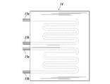
- FIG. 5 shows a schematic diagram of a configuration of a cooling pipe included in the irradiated object mounting table.
- FIG. 5 shows an example of two series of cooling pipe lines.
- the water that has absorbed heat by the irradiated object mounting table (14) is sent from the cooling pipe (exit side) (15b) to a chiller unit installed outside (not shown), and heat is exchanged inside the chiller unit.
- the cooling water whose temperature has been lowered is supplied again from the cooling pipe (incoming side) (15a) to the irradiated object mounting table (14).
- Cooling water circulates through the cooling pipe inside the chiller unit and the irradiated object mounting table (14).
- the water temperature of the cooling water introduced into the irradiated object mounting table (14) is preferably 30 ° C. or less, within the range where the mask (12) and the organic EL sheet (13) are not condensed, and is within the range of 10 to 20 ° C. It is more preferable.
- the material of the irradiated object mounting table is preferably a metal having high thermal conductivity, such as aluminum.
- reference lines (22) are formed at predetermined positions on the surface, for example, at the four corners of the irradiated object mounting table surface. ) Is provided.
- the reference line (22) may be a marking line or may be drawn with paint or the like.
- a plurality of suction portions (E) are provided on the surface of the light irradiation object mounting table (14) on the organic EL sheet (13), and the organic EL sheet is securely sucked into a predetermined position by suction. It is preferable to place it.
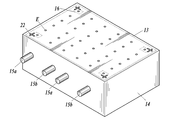
- FIG. 6 is a perspective view showing an example of a typical irradiated object mounting table having the above-described functions.
- Two pairs of cooling pipes (incoming side) (15a) and cooling pipes (outgoing side) (15b) are provided on the side surface portion of the irradiated object mounting table (14) shown in FIG. Then, a cooling pipe as shown in FIG. 5 is inserted to cool the irradiated body mounting table (14).
- Crossed reference lines (22) are provided at the four corners on the surface of the light irradiation object mounting table (14), and the organic EL elements (13) are formed at the four corners. It can be arranged at a predetermined position so as to coincide with the frame.
- the organic EL sheet (13) is sucked from the suction unit (E), and the organic EL sheet is placed on the irradiated body mounting table (14). The sheet (13) is brought into close contact.
- an organic EL sheet and a mask are placed on a light irradiation object mounting table having a cooling function, a cooling fluid is sprayed on the mask surface, and the organic EL sheet and the mask are attached.
- Light irradiation is performed in a sufficiently cooled state in advance to form a predetermined light emission pattern on the organic EL element, and then the supply of the cooling fluid is stopped after the light irradiation is completed. Is formed through the following steps.
- Step 1 Place a sheet-like organic EL sheet on which a plurality of organic EL elements are formed at a predetermined position of a light irradiation object mounting table having a cooling function.
- Step 2 The mask is arranged and adhered to a predetermined position of the organic EL sheet by alignment using an alignment mark.
- Step 3 spraying fluid on the surface of the mask
- Step 4 Irradiate the organic EL sheet through the mask
- Step 5 After the light irradiation is completed, the spraying of the fluid onto the mask surface is stopped.
- Step 1 is a process of placing a sheet-like organic EL sheet on which a plurality of organic EL elements are formed at a predetermined position of a light irradiation object mounting table having a cooling function.
- the light emitting pattern forming apparatus (1) has a configuration as shown in FIG. 1 in the final form at the time of light irradiation. However, in the preparation stage, the light source unit, the ask alignment apparatus, and the irradiated object mounting table are provided. These are arranged at separate positions by a predetermined configuration.
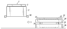
- FIG. 7 is a schematic layout diagram showing the configuration of the light source unit, the mask alignment apparatus, and the irradiated object mounting table in the preparation step of Step 1, and the light source unit (2) is positioned as the position A at the light irradiation position. Is the retreat position of the separated position C, the operation of placing the organic EL sheet (13) on the irradiated object placing table (14), and the position of the mask (12) in the mask alignment position on the mask alignment device (23). ) Is placed.
- the light irradiated object mounting table (14) is movable, and the organic EL sheet is installed at a retracted position away from the light source unit, and the organic EL sheet is collected after the light emission pattern is formed.
- FIG. 8 is a schematic diagram for explaining a specific method of placing the organic EL sheet on the irradiated object placing table.
- the organic EL sheet (13) is placed on a predetermined position of the irradiated object mounting table (14) in a state where the irradiated object mounting table (14) is in the retracted position.
- a predetermined position of the irradiated object mounting table (14) in a state where the irradiated object mounting table (14) is in the retracted position.
- the reference line (22) may be a marking line or a line drawn with paint or the like.
- the positioning of the organic EL sheet (13) to the irradiated object mounting table (14) is not the outer shape of the organic EL element (16) as described above, but the electrode portion (21) and a plurality of organic EL elements (16 ) May be used, an alignment mark that is given when manufacturing the device, a cut position indicating mark for cutting the organic EL element into individual pieces, a discard pattern, or the like.
- the organic EL sheet (13) After placing the organic EL sheet (13) at a predetermined position on the irradiated body placing table (14), the organic EL sheet (13) is sucked and fixed from the sucking part (E). Further, if necessary, a roller or the like is pressed against the entire organic EL sheet (13) in order to fit the entire organic EL sheet (13) to the surface of the irradiated object mounting table (14) having flatness. A means for close contact is also preferred.
- the irradiated object mounting table (14) has a cooling function using a chiller.
- a chiller having a water-cooled tube having a diameter of 10 mm ⁇ in aluminum having a thickness of 60 mm is used, and the temperature is 20 ° C. Of water can be circulated at a rate of 5 m 3 / min for cooling.
- the mask (12) is placed on the mask holder (24).
- an elevating part (25) for moving the mask holding table (24) up and down and a support base (26) for holding them are configured.
- This mask holder (24) can adjust X, Y, Z, and ⁇ in the XY plane.
- the mask (12) for example, a photosensitive material applied to a glass substrate (quartz glass), a line and space with a half pitch of 0.3 mm (a length of 2 mm in which white (transparent) and black alternate every 0.3 mm).
- a glass mask in which a large number of patterns in which a linear pattern is arranged at 45 degrees in the vertical, horizontal, and diagonal directions can be used.
- the light irradiation device section has a narrow WD in order to secure high irradiance, and it is difficult to replace the mask (12) at the light irradiation position. is there. Therefore, a mask alignment apparatus is arranged next to the light source unit so that mask exchange and mask alignment are possible.
- Step 2 moves the irradiated object mounting table including the organic EL sheet to the alignment position of the mask alignment apparatus including the mask, and then associates the mask and the organic EL sheet at a predetermined position. It is the process of making it adhere.
- the irradiated object mounting table is moved to the position of the mask alignment apparatus.
- FIG. 9 is a schematic view showing an example of moving the irradiated object mounting table (14) to the position of the mask alignment apparatus (23).
- the mask (12) is placed on the mask holder (24) by its own weight, and the mask holder (24) is raised by the elevating part (25).
- the irradiated object mounting table (14) on which the organic EL sheet (13) is mounted is moved to just below the mask (12) of the mask alignment apparatus (23).
- the mask holding table (24) is lowered to the point where the organic EL sheet (13) and the mask (12) are in close contact with each other.
- FIG. 10A and FIG. 10B are schematic cross-sectional views observed from different positions in an example of a method in which the organic EL sheet on the irradiated object mounting table and the mask on the mask alignment apparatus are brought into close contact with each other at a predetermined position.
- the plurality of cameras (28) are moved to the alignment unit (27) position on the mask (12), and the organic EL
- the organic EL sheet alignment mark (17) provided in the sheet (13) and the mask alignment mark (20) provided in the mask (12) are recognized.
- each alignment mark may be performed using only two diagonal positions.
- FIG. 10B is a schematic cross-sectional view of the mask alignment apparatus shown in FIG. 10A described above as viewed from a position moved 90 degrees.
- the mask holding base (24) is further lowered, and the mask (12) is separated from the mask holding base (24), and due to the weight of the mask (12).
- the organic EL sheet adheres at a predetermined position.
- Arranging the light shielding film of the mask (12) on the surface side of the organic EL sheet (13) allows the heat of the light shielding film, which generates heat by absorbing ultraviolet rays, to pass through the organic EL sheet (13). It is desirable in that it can escape to the light irradiation body mounting table (14). Further, it is preferable in that curling of the organic EL sheet (13) is suppressed, the floating portion is eliminated, and accurate patterning is possible.
- the organic EL sheet (13) and the mask (12) are cooled by the cooling function of the irradiated object mounting table (14).
- Step 3 is a step of spraying a fluid onto the surface of the mask of the irradiated object mounting table moved to the light irradiation position.
- FIG. 12 is a schematic cross-sectional view showing spraying of a cooling fluid onto the mask surface before light irradiation for forming a light emitting pattern.
- the layered mask cooling fluid (11) is applied from the fluid generator (10) to the surface of the mask (12) on which the irradiated object mounting table (14) moved to the light irradiation position is mounted.
- Spray A flow meter is installed between the fluid generator (10) and a fluid supply source (not shown), and constantly monitors the flow rate of the fluid, for example, air.
- An anemometer may be installed in front of the blowout port of the part that is outside the light irradiation area in the longitudinal direction of the fluid generating part (10), and the wind speed may be monitored.
- the mask and the like are sufficiently cooled before light irradiation.
- Slit position of spraying part 3mm above glass
- Angle of sprayed part of air flow generating part parallel to mask (0 degree)
- a distance (d) between the air flow generator and the housing was 72 mm, and a pair of fluid generators were attached at positions facing the side surface of the housing.
- Step 4 Light irradiation through a mask
- the fluid generating part (10) forms a layer.
- ultraviolet light (8) is irradiated to form a light emission pattern.
- the irradiation of the ultraviolet ray at the light source unit (2) is started after the flow rate of the mask cooling fluid (11) reaches 1000 L / min or more.
- the ultraviolet irradiation condition in the present invention there is a method in which 40 W of a cycle of irradiation time of 15 seconds and turn-off of 15 seconds is performed 40 times with intermittent irradiation of 4 W / cm 2 as irradiance, and light irradiation is performed for 10 minutes as an integration time.
- a cycle of irradiation time of 15 seconds and turn-off of 15 seconds is performed 40 times with intermittent irradiation of 4 W / cm 2 as irradiance, and light irradiation is performed for 10 minutes as an integration time.
- the light emission pattern formation method of this invention is the method of performing light irradiation collectively through a mask with respect to all the organic EL elements arrange
- the organic EL sheet may be divided into a plurality of regions, and a divided light irradiation method in which light is irradiated through a mask for each divided region may be used.
- FIGS. 14A and 14B are schematic plan views showing an example of a light irradiation pattern (collective light irradiation method, split light irradiation method) for the organic EL sheet.
- FIG. 14A shows an example of a method of performing collective light irradiation in the light irradiation area (A) for the total number of organic EL elements (16) arranged on the organic EL sheet (13).
- the method shown in FIG. 14B shows a method in which the organic EL sheet (13) is divided into four areas (divided area I, divided area II, divided area III, divided area IV), and light is irradiated for each divided area. is there.
- Step 5 is a step of stopping spraying the fluid onto the mask surface after the light irradiation is completed.
- the mask holder (24) is raised at the mask alignment position, and the mask (12) and the organic EL sheet (13) on which the light emission pattern is formed are separated.
- the irradiated object mounting table (14) on which the organic EL sheet (13) on which the light emission pattern is formed is placed is moved to the evacuation position which is the position C shown in FIG. 7, and suction by the suction unit (E) is stopped. Then, the organic EL sheet (13) is collected.
- the mask alignment device (23) and the irradiated object mounting base (14) may be integrated and moved as a whole.
- the entire position of the apparatus can be saved by setting the alignment position and the retracted position at the same position.
- organic EL sheet placement / recovery, mask alignment, and mask replacement are performed at the same position of the alignment position and the retracted position.
- a light emission pattern is formed on an organic EL element mainly through S101 to S113 shown in FIG.
- S101 Preliminarily set conditions for irradiating the organic EL sheet with light (setting conditions: irradiance, one pulse irradiation time and extinguishing time and number of cycles, and in the case of divided irradiation method, irradiation order of each irradiation area)
- S102 Place the organic EL sheet on the light irradiation object mounting table and perform suction fixation (see FIGS. 6 and 8).
- S103 Refer to placing a mask on the mask alignment apparatus (position B in FIG. 7). (Normally, the mask is placed on the mask alignment apparatus while it is installed.
- S104 The irradiated object mounting table and the mask alignment apparatus are associated with each other at the mask alignment position (see FIG. 9).
- S105 The alignment mark of the organic EL sheet and the alignment mark of the mask are used to align the positions of the organic EL sheet and the mask, the mask holder of the mask alignment apparatus is lowered, and the organic EL sheet and the mask are brought into contact with each other (see FIG. 10)
- S106 Move the irradiated object mounting table on which the mask and the organic EL sheet are mounted to the light irradiation position (see FIG. 11).
- S107 The cooling fluid is started to be sprayed from the fluid generating portion to the mask surface (see FIG.
- S108 Confirm that the flow rate of the cooling airflow reaches 1000 L / min.
- S109 Irradiate the organic EL sheet according to a predetermined light irradiation pattern (see FIGS. 1, 13, and 14).
- S110 The formation of the light emission pattern is completed and the light irradiation to the organic EL sheet is stopped.
- S111 The blowing of the cooling airflow to the mask is stopped.
- S112 The irradiated object mounting table is moved to the mask alignment position (see FIG. 15).
- S113 Raise the mask holding table of the mask alignment apparatus to separate the mask and the organic EL sheet.
- S114 Move the irradiated object mounting table to the retracted position, stop the suction, and form the light emission pattern. Collect the sheet.
- the method for forming a light emitting pattern of an organic EL element according to the present invention suppresses thermal deformation of a mask during pattern formation and thermal damage to a plurality of organic EL elements, and can form a pattern on a plurality of organic EL elements at a time.
- a light-emitting pattern can be formed with excellent and high dimensional accuracy, and the organic electroluminescence element can be patterned and applied to various displays used as a panel.
Landscapes
- Engineering & Computer Science (AREA)
- Manufacturing & Machinery (AREA)
- Electroluminescent Light Sources (AREA)
Abstract
本発明の課題は、パターン形成用マスクの熱変形と複数の有機EL素子に対する熱ダメージを抑制し、一度に複数の有機EL素子にパターン形成ができ、生産性に優れ、かつ寸法精度の高い発光パターン形成が可能な有機EL素子の発光パターン形成方法を提供することである。 本発明の有機EL素子の発光パターン形成方法は、1)複数の有機EL素子が形成されている枚葉状の有機EL素子シートを、冷却機能を備えている被光照射体載置台の所定の位置に載置し、2)マスクを、アライメントマークを用いたアライメントにより、前記有機EL素子シートの所定の位置に配置及び密着させ、3)前記マスクの表面に流体を吹き付け、4)前記マスクを介して、前記有機EL素子シートに光照射を行い、5)前記光照射完了後に、前記流体のマスク表面への吹付を停止するステップを経て形成されることを特徴とする。
Description
本発明は、冷却機能を備えたパターン形成用光照射装置を用いた有機エレクトロルミネッセンス素子の発光パターン形成方法に関する。より詳しくは、本発明は、冷却機能により、パターン形成時のマスクの熱変形と有機エレクトロルミネッセンス素子に対する熱ダメージを抑制し、生産性が高く、寸法精度の高い発光パターン形成が可能な有機エレクトロルミネッセンス素子の発光パターン形成方法に関する。
現在、薄型の発光デバイスとして有機発光パネルが注目されている。例えば、有機材料のエレクトロルミネッセンス(Electro Luminescence:EL)を利用した有機発光素子(以下、「有機EL素子」ともいう。)は、数V~数十V程度の低電圧で発光が可能な薄膜型の完全固体パネルであり、低電力で高い輝度を得ることができ、視認性、応答速度、寿命、消費電力等に優れ、薄型化、軽量化できるといった多くの優れた特徴を有している。このため、有機EL素子をパネルとして用いた各種ディスプレイや、そのバックライト、看板や非常灯等の表示板、照明光源等の面発光体として適用する方法が近年注目されている。
このような有機ELパネルは、2枚の電極間に有機材料等により構成される発光層が配置され、発光層で生じた発光光は、電極を透過して外部に取り出される。このため、2枚の電極のうちの少なくとも一方は透明電極として構成され、透明電極側から発光光が取り出される。
有機ELパネルをディスプレイ用途に用いる場合、有機EL素子に発光パターンを付与する方法が用いられている。
有機EL素子に発光パターンを形成する方法としては、例えば、製造した有機EL素子の有機機能層に対して紫外線等の活性エネルギー線を照射し、当該照射部分の発光機能を失活させることで非発光領域を形成し、この非発光領域を有する発光パターンを形成する発光表示素子の製造方法が開示されている(例えば、特許文献1参照。)。当該特許文献1に記載されている方法では、マスクを使用して紫外線照射により発光パターンを形成する方法は記載されているが、有機EL素子やマスクを冷却する方法に関しては一切の配慮がなされていない。また、特許文献1に記載されている方法では、それぞれ個々の有機EL素子単体ごとに光照射行う、いわゆるバッチ方式でパターニングを行う方法であり、この方法では、生産性が低く、発光パターンを有する有機EL素子の需要が高まるにつれ、一度に複数の有機EL素子に発光パターンを形成することのできる高い生産性等の要望に対応している方法であるとは言い難い。また、上記方法で生産性を高めるためには、光照射装置を多数配置させる必要があり、経済的な負荷も大きい。
一方、生産性を高める方法として、ロールtoロール法や湿式塗布法で有機EL素子を製造する場合、複数の有機EL素子を基板上に形成したのち、所定長さで基板を切断する。次いで、所定の長さに切断した有機EL素子を有するシートの状態で、複数の有機EL素子に対し、一括して光照射することにより、一度で多数の有機EL素子に対してパターニングを行うことが可能となり、生産効率を向上させることできる。
さらに、国際公開第2014-175135号に記載されているように、光照射時の放射照度を高めるとパターニングの反応速度が加速するため、高い放射エネルギー照度下で有機ELシートに光照射することにより、タクト時間の短縮とスループット向上が可能となるとされている。この場合、高い放射エネルギー照度で広いエリアに光照射することになり、光照射、例えば、紫外線を照射する有機EL素子上に載置されているマスクの遮光膜が紫外線を吸収して温度が上昇し、その結果、熱変形を生じて、マスクの遮光膜パターン寸法がずれること、マスクがたわみ、マスクと有機EL素子の間に間隙が生じて、光照射された画像のボケが発生すること等の問題が発生し、正確な発光パターンを有機EL素子に形成することが困難であった。極端な場合には、マスクがガラス製である場合には、熱膨張により破損することもあった。
さらに、半導体や液晶表示装置などの回路製造で用いられるフォトレジストに比べ、有機EL素子はその構造が複雑であるため、有機EL素子自体が熱に対し、より脆弱である。具体的には、熱により有機材料の膜質変化が起こり、発光効率、色度の変動や素子寿命の低下が生じてしまうという問題があった。特に、青色光、緑色光、赤色光を混色して白色発光させる場合に、色バランスが保ちにくいため、許容幅が狭く、熱に対してより影響されやすく、その結果、色バランスを崩しやすいという有機EL素子特有の問題がある。
上記のような問題に対し、被光照射体である液晶ディスプレイ(LCD)のガラス基板に近接光照射する方法で、ガラス基板を光照射台に搬送してからガラス基板の冷却を開始し、光照射位置に移動させて光照射し、光照射が終了し、排出搬送するまで、ガラス基板を冷却する方法が開示されている(例えば、特許文献2参照。)。しかしながら、特許文献2においては、カラス基材を冷却する方法であり、有機EL素子のパターニングに用いるマスクを冷却し、光照射時の熱変形等を防止し、高精度の発光パターンを形成する方法や、複数の被光照射体(例えば、有機EL素子)に対し、まとめて光照射することにより生産性を高める方法に関しては全く言及がなされていない。
また、液晶ディスプレイの製造工程において、ガラス基板上にフォトマスクのパターンを形成するプロキシミティ光照射装置において、光照射時のフォトマスクの温度を調整する方法として、フォトマスクの上方より、冷却用のエアーを吹き付ける方法が開示されている(例えば、特許文献3参照。)。しかしながら、特許文献3に記載の方法には、フォトマスクに対する冷却用のエアーの吹き付けのタイミング等に関する記載はなされていない。
近接光照射のためのフォトマスクは、光源部の下部に常時配置されており、エアーを常時吹き付けることも想定されるが、有機ELシートに高放射照度で、広エリアに対し光照射する場合には、マスク冷却エアーは1000L/分以上と大量のエアー量が必要となる。この場合、エアー吹き付けにかかるランニングコストは無視できないレベルであり、光照射時以外は吹き付けを停止させることが望ましいが、特許文献3にはそのような課題提起や配慮はなされていない。加えて、複数の被光照射体(例えば、有機EL素子)に対し、まとめて光照射することにより生産性を高める方法に関しては全く言及がなされていない。
本発明は、上記問題・状況に鑑みてなされたものであり、その解決課題は、効率的なマスクの冷却機能を具備し、パターン形成時のマスクの熱変形と複数の有機EL素子に対する熱ダメージを抑制し、一度に複数の有機EL素子にパターン形成ができ、生産性に優れ、かつ寸法精度の高い発光パターン形成が可能な有機EL素子の発光パターン形成方法を提供することである。
本発明者は、上記課題を解決すべく、上記問題の原因等について検討した結果、複数の有機EL素子が配置されている有機ELシートを、冷却機能を備えている被光照射体載置台に載置し、次いでマスクをアライメントにより有機ELシートの所定の位置に配置及び密着させ、次いでマスクの表面に流体を吹き付けてマスクを冷却しながら、マスクを介して有機ELシートに光照射を行って発光パターンを形成し、光照射完了後に冷却用の流体のマスク表面への吹付を停止するステップを経て有機EL素子の発光パターンを形成する方法により、上記課題を解決できることを見いだし本発明に至った。
すなわち、本発明に係る上記課題は、以下の手段により解決される。
1.有機エレクトロルミネッセンス素子にマスクを介して光照射を施し、発光パターンを形成する有機エレクトロルミネッセンス素子の発光パターン形成方法であって、
下記のステップ1からステップ5を経て、前記有機エレクトロルミネッセンス素子に発光パターンを形成することを特徴とする有機エレクトロルミネッセンス素子の発光パターン形成方法。
下記のステップ1からステップ5を経て、前記有機エレクトロルミネッセンス素子に発光パターンを形成することを特徴とする有機エレクトロルミネッセンス素子の発光パターン形成方法。
ステップ1:複数の有機エレクトロルミネッセンス素子が形成されている枚葉状の有機エレクトロルミネッセンス素子シートを、冷却機能を備えている被光照射体載置台の所定の位置に載置するステップ
ステップ2:前記マスクを、アライメントマークを用いたアライメントにより、前記有機エレクトロルミネッセンス素子シートの所定の位置に配置及び密着させるステップ
ステップ3:前記マスクの表面に流体を吹き付けるステップ
ステップ4:前記マスクを介して、前記有機エレクトロルミネッセンス素子シートに光照射を行うステップ
ステップ5:前記光照射完了後に、前記流体のマスク表面への吹付を停止するステップ。
ステップ2:前記マスクを、アライメントマークを用いたアライメントにより、前記有機エレクトロルミネッセンス素子シートの所定の位置に配置及び密着させるステップ
ステップ3:前記マスクの表面に流体を吹き付けるステップ
ステップ4:前記マスクを介して、前記有機エレクトロルミネッセンス素子シートに光照射を行うステップ
ステップ5:前記光照射完了後に、前記流体のマスク表面への吹付を停止するステップ。
2.前記ステップ3における流体の流量が1000L/min以上となってから、前記ステップ4における光照射を開始することを特徴とする第1項に記載の有機エレクトロルミネッセンス素子の発光パターン形成方法。
3.前記ステップ1及びステップ2を、前記ステップ4の光照射位置から離れた位置で行い、前記被光照射体載置台に前記有機エレクトロルミネッセンス素子シートと前記マスクを載置した状態で、前記光照射位置に移動し、光照射前に前記ステップ3で前記マスクの表面に流体を吹き付けることを特徴とする第1項又は第2項に記載の有機エレクトロルミネッセンス素子の発光パターン形成方法。
4.前記ステップ4における光照射が、有機エレクトロルミネッセンス素子シートに配置されている有機エレクトロルミネッセンス素子の全数に対し、前記マスクを介して、一括して光照射を行うことを特徴とする第1項から第3項までのいずれか一項に記載の有機エレクトロルミネッセンス素子の発光パターン形成方法。
5.前記ステップ4における光照射が、有機エレクトロルミネッセンス素子シートを複数の領域に分割し、分割した領域ごとに、マスクを介して光照射することを特徴とする第1項から第3項までのいずれか一項に記載の有機エレクトロルミネッセンス素子の発光パターン形成方法。
本発明の上記手段により、効率的なマスクの冷却機能を具備し、パターン形成時のマスクの熱変形と複数の有機EL素子に対する熱ダメージを抑制し、一度に複数の有機EL素子にパターン形成ができ、生産性に優れ、かつ寸法精度の高い発光パターン形成が可能な有機EL素子の発光パターン形成方法を提供することができる。
本発明の効果の発現機構ないし作用機構については、以下のとおりである。
本発明の有機EL素子の発光パターン形成方法は、有機EL素子に光照射、例えば、紫外線を照射して非発光部を形成し、パターニングを行う方法であり、この方法は、複数の有機EL素子が平面配置されている大版の有機ELシートへ高放射照度の光照射でパターニングを行う場合に最適な方法である。
基本的なステップは、有機ELシートとマスクを、冷却機能を具備した被光照射体載置台に載置し、マスク表面に気流、例えば、エアーを吹き付け、有機ELシートとマスクを予め十分に冷却した状態で光照射を行って発光パターンを形成した後、気流を停止する方法である。
通常、複数の有機EL素子が配置されている有機ELシートに対する光照射は、光照射エリアが広くなり、照射全光量として高い放射照度量が必要となる。その結果、光照射による発熱量が増加し、マスク等の変形を引き起こすと共に、有機EL素子に熱ダメージを与えてしまうが、本発明で規定するステップに従って、冷却及び光照射を行うことにより、光照射エリアが広くなっても、マスクの熱変形(膨張、反り)を十分抑制でき、正確なパターニングが可能となり、熱に弱い有機EL素子の有機機能層に対しても、熱ダメージを与えることなくパターニングができ、高い発光性能を確保することができる。
すなわち、本発明では、冷却機能を有する被光照射体載置台に有機ELシートとマスクを所定位置に載置して予め冷却させておき、マスク冷却エアーを光照射前にマスクに吹き付けることにより、有機ELシートとマスクを十分冷却した状態で光照射を開始することができ、マスク熱変形や有機EL素子の熱ダメージを抑制して正確なパターニングができるようにしたものである。
更に、マスクへのエアーの吹き付け操作は、必要な時のみ行うことにより、エアーに関するランニングコストを低減できる。
本発明の有機エレクトロルミネッセンス素子の発光パターン形成方法は、有機エレクトロルミネッセンス素子にマスクを介して光照射を施し、発光パターンを形成する方法であって、前記ステップ1から前記ステップ5を経て、前記有機エレクトロルミネッセンス素子に発光パターンを形成することを特徴とする。この特徴は、各請求項に共通する又は対応する技術的特徴である。
本発明の実施態様としては、本発明の効果発現の観点から、本発明に係るステップ3における流体の流量が1000L/min以上となってから、本発明に係るステップ4における光照射を開始するフローとすることが、光照射前に確実にマスク等の冷却を行うことができ、高い精度で、かつ安定して発光パターンを形成することができる点で好ましい。
また、本発明に係るステップ1の有機ELシートの被光照射体載置台への載置と、本発明に係るステップ2のマスクを、被光照射体載置台上の有機ELシートの所定の位置に密着させる操作を、本発明に係るステップ4の光照射位置から離れたポジションで行い、かつ被光照射体載置台に有機ELシートとマスクを載置した状態で、光照射位置に移動し、ステップ3として光照射前にマスク表面に流体を吹き付けるフローとすることが、光照射を開始するまでの間に、有機ELシートとマスクを十分に冷却することができる点で好ましい。
また、発光パターンの形成方法として、有機ELシートに配置されている有機EL素子の全数に対し、マスクを介して、一括して全数の有機EL素子に対し光照射を行う方法が、発光パターンの形成時間を短縮させることができ、高い生産性を達成することができる点で好ましい。
また、発光パターンの形成方法として、有機ELシートを複数の領域に分割し、分割した領域ごとに、マスクを介して、複数回で光照射することが、光照射面積を狭くすることにより、光照射による過大の熱量の発生を抑制することができ、マスクの変形等を防止し、高精度の発光パターンを形成することができる点で好ましい。
上記2つの発光パターンの形成方法については、要求される発光パターンの精度及び生産性等を考慮し、最適な条件を適宜設定することが好ましい。
以下、本発明とその構成要素、及び本発明を実施するための形態・態様について詳細な説明をする。なお、本願において、「~」は、その前後に記載される数値を下限値及び上限値として含む意味で使用する。なお、各図の説明において、構成要素の末尾の括弧内に記載した数字は、各図に記載されている符号を表す。
《発光パターンの形成方法及び形成装置の全体概要》
本発明の有機EL素子の発光パターン形成方法は、有機EL素子にマスクを介して光照射を施し、発光パターンを形成する有機EL素子の発光パターン形成方法であって、
下記に示すステップ1からステップ5を経て、前記有機EL素子に発光パターンを形成することを特徴とする。
本発明の有機EL素子の発光パターン形成方法は、有機EL素子にマスクを介して光照射を施し、発光パターンを形成する有機EL素子の発光パターン形成方法であって、
下記に示すステップ1からステップ5を経て、前記有機EL素子に発光パターンを形成することを特徴とする。
ステップ1:複数の有機EL素子が形成されている枚葉状の有機ELシートを、冷却機能を備えている被光照射体載置台の所定の位置に載置するステップ
ステップ2:前記マスクを、アライメントマークを用いたアライメントにより、前記有機ELシートの所定の位置に配置及び密着させるステップ
ステップ3:前記マスクの表面に流体を吹き付けるステップ
ステップ4:前記マスクを介して、前記有機ELシートに光照射を行うステップ
ステップ5:前記光照射完了後に、前記流体のマスク表面への吹付を停止するステップ。
ステップ2:前記マスクを、アライメントマークを用いたアライメントにより、前記有機ELシートの所定の位置に配置及び密着させるステップ
ステップ3:前記マスクの表面に流体を吹き付けるステップ
ステップ4:前記マスクを介して、前記有機ELシートに光照射を行うステップ
ステップ5:前記光照射完了後に、前記流体のマスク表面への吹付を停止するステップ。
本発明の有機EL素子の発光パターン形成方法に適用する発光パターン形成装置は、主には、有機EL素子の発光機能を低下させてパターンを形成するための紫外線等を照射する照射光発生部と、照射光発生部から発せられた紫外線等を反射導光する筐体により構成されている光源部と、その下部に紫外線が照射されるマスクと、発光パターンを形成する有機ELシートを載置した被光照射体載置台から構成されている。さらに、マスクと筐体との間隙を通して、マスク冷却用流体、例えば、空気をマスクと平行に、かつマスクの中央方向に吹き付けられるよう配置された一対の流体発生部が備えられている。以下、本発明の有機EL素子の発光パターン形成方法として、照射光の代表例として「紫外線」を用いる方法について説明する。
以下、図面を用いて、発光パターン形成装置の具体的な構成について説明する。
図1は、本発明に適用可能な発光パターン形成装置の一例を示す全体構成図である。
図1に示す発光パターン形成装置(1)は、主には、紫外線発生部(8)を含む光源部(2)と、被光照射体載置台(14)と、流体発生部(10)等より構成されている。
紫外線発生部(8)には、LED基板(4)上に、紫外線を出射する光源として、例えば、発光波長が365nmや385nmのLED(5)を平面状に並列配置し、LED(5)から出射した発散光を、レンズアレイ(7)で所定の広がり角の光束に整形し、反射導光する筐体(9)を通じて、その下部に位置するマスク(12)を介して、発光パターンを、被光照射体載置台(14)に保持されている有機ELシート(13)に光照射する。
レンズアレイ(7)から出射した紫外光は、内面が反射面となっている筐体(9)の内部に閉じ込められ、光量の低下を防ぎ、かつ均一な光量でマスク(12)に光照射される。
また、光照射エリア周辺部の光量を確保するためには、筐体(9)の下端とマスク(12)の間隔(WD)はできるだけ狭い方が良く、5mm程度が望ましい。この間隔であれば、マスクに層状の流体を一様に吹き付けることができる。
LED(5)は、コントローラ(不図示)により点灯、消灯や点灯時の照射出力、照射時間が制御され間欠光照射を行う。図1の説明においては、広がり角の整形手段としてレンズアレイ(7)を用いたが、複合放物面集光器のような集光ミラーを用いてもよい。
また、紫外線発生部(8)の上部には、LEDの発光により生じた熱を、外部に放出するための放熱板(3)を具備していることが好ましい。このような放熱板(3)を設置することにより、光源部(2)の温度上昇を抑制することができる。
有機ELシート(13)は被光照射体載置台(14)に載置され、マスク(12)は有機ELシート(13)と所定の相対位置に調整され、有機ELシート(13)上に載置される。この時、有機ELシート(13)は、被光照射体載置台(14)に吸着固定する方法を適用することが好ましい。
有機ELシート(13)が基板として、例えば、ポリエチレンテレフタレート(略称:PET)やポリエチレンナフタレート(略称:PEN)を樹脂成分とする樹脂フィルムを用いた場合、有機ELシート(13)が変形し易いが、有機ELシート(13)の全面を、被光照射体載置台(14)に吸着密着させて固定することにより、平面性よく、発光パターン形成時の光照射ボケを防止できる点で好ましい態様である。
被光照射体載置台(14)には、水冷方式により有機ELシート(13)を冷却する機能を具備していることが好ましい態様である。例えば、被光照射体載置台(14)の内部に、冷却管をはりめぐらし、紫外線照射によりマスク(12)や有機ELシート(13)で発生した熱を、冷却水等により冷却する手段を備えていることが好ましい。
本発明に係る発光パターン形成装置(1)においては、マスク(12)と筐体(9)との間に、マスク冷却用流体(11)、例えば、空気をマスク(12)と平行に、かつマスク(12)の中央方向に吹き付けられるよう配置された一対の流体発生部(10)を備えていることを特徴とする。
このような構成とすることにより、中央方向に、マスク(12)と平行に吹き付けられたマスク冷却用流体(11)は、マスク(12)面の冷却をむらなく行うとともに、中央部で合流した空気流が筐体(9)上部に上昇して、紫外線発光部(8)に到達し、さらには筐体(9)側面に沿って下降し対流する。このように、筐体(9)内部の空気循環(対流)を促進して、筐体(9)内部で温度上昇した空気を冷却するとともに、筐体(9)も効率的に冷却することができる。吹き付けられた空気は、熱を吸収して筐体(9)内部を循環して、空気流発生部(10)が備えられている面の隣り合った側面から排気される。
《発光パターン形成装置の構成部材》
〔紫外線発光部》
紫外線発光部には、紫外線を発光する光源が取り付けられている。光源としては、所望の紫外線を発光する光源であれば、特に制限はない。本発明でいう紫外線とは、その波長がX線よりも長く、可視光の最短波長よりも短い電磁波をいい、具体的には波長領域が、1~400nmの範囲内であるが、好ましくは、適用する照射光の波長としては、355nm、365nm、380nm、405nm等に極大波長を有する照射光を用いることが好ましい。
〔紫外線発光部》
紫外線発光部には、紫外線を発光する光源が取り付けられている。光源としては、所望の紫外線を発光する光源であれば、特に制限はない。本発明でいう紫外線とは、その波長がX線よりも長く、可視光の最短波長よりも短い電磁波をいい、具体的には波長領域が、1~400nmの範囲内であるが、好ましくは、適用する照射光の波長としては、355nm、365nm、380nm、405nm等に極大波長を有する照射光を用いることが好ましい。
本発明に適用可能な紫外線を発光する光源としては、例えば、LED、超高圧水銀灯、高圧水銀灯、低圧水銀灯、カーボンアーク、メタルハライドランプ、キセノンアークランプ、カーボンアークランプ、エキシマランプ、UV光レーザー等を用いることができる。
この中でも、電気的にパルス照射制御が容易で、光源の高出力化が可能である、図1で例示したような紫外線を出射するLED(5、以下、「UV-LED」ともいう。)を用いることが好ましい。
UV-LEDとは、250~400nmの波長をもつLEDであり、UV-LEDは更には、350~400nmの範囲に発光波長を有するUVA-LED、280~350nmの範囲に発光波長を有するUVB-LED、250~280nmの範囲に発光波長を有するUVC-LEDがあり、それぞれの用途に応じて、適宜選択して用いる。
UV-LEDの発光材料としては、窒化物半導体、例えば、GaN、InGaN、AlGaNなどが挙げられる。
本発明に係る紫外線発光部(8)では、LED基板(4)上に、複数個のLED(5)を平面状に配置し、発光部を形成している。LED(5)の光照射側には、レンズアレイ支持体(6)を介してレンズアレイ(7)が設けられており、LED(5)から出射した発散光を、所定の広がり角の光束に整形する。
紫外線の照射量は、有機ELシートのサイズにもよるが、200~5000J/cm2の積算光量で照射することができる。また、間欠照射における1パルスの紫外線照射時間は、1~300秒の範囲内であることが好ましい。
〔筐体〕
反射導光する筐体(9)は、紫外線発光部(8)から照射された紫外光(L)光量の低下を防ぎ、かつ均一な光量でマスクに照射させる機能を有している。そのために、内面が反射材料により被覆されている構成であることが好ましい。反射材料としては、熱に対する耐性や耐久性があることから、金属材料を用いることができる。例えば、軽量でもあることから、アルミニウムを好ましく使用することができる。
反射導光する筐体(9)は、紫外線発光部(8)から照射された紫外光(L)光量の低下を防ぎ、かつ均一な光量でマスクに照射させる機能を有している。そのために、内面が反射材料により被覆されている構成であることが好ましい。反射材料としては、熱に対する耐性や耐久性があることから、金属材料を用いることができる。例えば、軽量でもあることから、アルミニウムを好ましく使用することができる。
筐体(9)は、その上部に紫外線発光部(8)が取り付けられ、その下端にマスク(12)との間隙(WD)を有していれば、その高さや、底面積は、特に制限がなく、紫外線を照射する有機ELシート(13)の大きさに応じて設定することができる。底面は、作製するパターンより大きいことが好ましい。
本発明においては、有機ELシート(13)が大きく、照射光量の大きい場合の紫外線照射時の冷却に特に効果的であることから、例えば、0.1~7m2の大きさの有機ELシートの製造に効果的である。また、本発明によれば、寸法精度の高いパターニングが可能であることから、複数の有機EL素子を一回の紫外線照射プロセスで作製することで、生産性を高めることもできる。
筐体の高さは、紫外線の光量、照射光量のばらつきなどから、適宜調整できる。
筐体の具体的な構成の一例を以下に示す。
寸法:W1155mm×D784.5mm×H2500mm
材質:アルミ製内壁の反射板(厚さ1.5mm)/空気層(厚さ5mm)/アルミ製外壁(厚さ7.5mm)のアルミニウムサンドウイッチ構造を有する筐体を一例として挙げることができる。
材質:アルミ製内壁の反射板(厚さ1.5mm)/空気層(厚さ5mm)/アルミ製外壁(厚さ7.5mm)のアルミニウムサンドウイッチ構造を有する筐体を一例として挙げることができる。
筐体とマスクの間隙:5.0mm
〔流体発生部〕
図1で示したように、本発明に係る流体発生部(10)は、マスク(12)上面の対向する位置に、マスク(12)と筐体(9)との間隙(WD)を通して、マスク冷却用流体(11、以下単に「流体」ともいう。)、例えば、空気をマスク(12)と平行に、かつマスク(12)の中央方向に吹き付けられるよう配置されている。
〔流体発生部〕
図1で示したように、本発明に係る流体発生部(10)は、マスク(12)上面の対向する位置に、マスク(12)と筐体(9)との間隙(WD)を通して、マスク冷却用流体(11、以下単に「流体」ともいう。)、例えば、空気をマスク(12)と平行に、かつマスク(12)の中央方向に吹き付けられるよう配置されている。
両端部に配置されている一対の流体発生部(10)は、マスク(12)の上面部に位置し、マスク(12)と平行に流体を吹き付けることにより、吹き付けられる流体(11)は、むらなくマスク(12)上を進み、マスク(12)の中央部で合流する。平行に吹き付けるとは、マスク(12)の平面に対し±2度以内の角度で吹き付けることをいう。マスク(12)平面に対し2度を超えて上向きに吹き付けた場合は、マスク(12)の冷却が不十分となる。また、マスク(12)平面に対し2度を超えて下向きに吹き付けた場合は、マスク(12)に吹き付けられた空気に乱れが生じ、マスク(12)の冷却にむらが生じ、中央部で合流した空気が、筐体(9)内部で乱流を発生させてしまい、前述した対流が起こらず、冷却が効率的にならないため好ましくない。
マスク(12)に吹き付けられた流体(11)は、マスク(12)の中央部で合流する。中央で合流することで、マスク(12)及び筐体(9)をむらなく冷却することができる。このため2基の流体発生部(10)は、マスク(12)上面の対向する位置に平行に配置される。また、筐体(9)の吹き付けられる側の側面とも平行であることが好ましい。
筐体(9)と流体発生部(10)との距離(d)は、空気が効率よくマスク(12)に吹き付けられれば特に制約はないが、10~200mmの範囲内であることが好ましい。より好ましくは50~100mmの範囲内である。また、流体発生部(10)の長さは、吹き付ける側の筐体(9)の幅と同じか、それより大きいほうが好ましい。
流体発生部(10)から吹き付けられた流体(11)は、マスク(12)と筐体(9)との間隙(WD)を通してマスク(12)に吹き付けられる。この間隙(WD)は、筐体内部への空気の出し入れ口の機能を有するが、吹き付けられた流体(11)、例えば、空気が、効率よく筐体(9)内を循環することに対しても影響する。間隙(WD)としては、2~20mmの範囲内であることが好ましく、より好ましくは3~10mmの範囲内である。間隙が20mm以内であれば、筐体(9)内での流体の循環が効率的に行われ、2mm以上あれば、冷却するための風量を十分に得ることができる。
また、一対の流体発生部(10)は、筐体(9)、及びマスク(12)の中央部に対して対称の位置に配置されることが好ましい。流体発生部から吹き付けられた気流による冷却に加えて、マスク(12)の下部には、水冷管を有する被光照射体載置台(14)を備えられ、有機ELシートを介してマスクを冷却することが望ましい。
〈流体の吹き付け部〉
筐体(9)内部の空気循環を行い、効率よくマスク(12)や筐体(9)を冷却するため、流体発生部(10)としては、スリット状又はノズル状の吹き付け部を備えたものであることが好ましい。スリット状の吹き付け部を備えたものであることが、より好ましい。
筐体(9)内部の空気循環を行い、効率よくマスク(12)や筐体(9)を冷却するため、流体発生部(10)としては、スリット状又はノズル状の吹き付け部を備えたものであることが好ましい。スリット状の吹き付け部を備えたものであることが、より好ましい。
スリット状の吹き付け部を備えた流体発生部は、層状の流体を吹き付けることができる。例えば、間隙が50~100μm程度の薄いスリットから、高速で噴出された空気は、周辺の空気を大量に巻き込み層状の空気を、マスク(12)表面及び筐体(9)表面に吹き付けることができる。このような層状の空気を吹き付けることで、マスク(12)と筐体(9)とを効率的に冷却することができる。
スリット状の吹き付け部の代わりに、ノズル状の吹き付け部を備えたものも使用できるが、その場合、ノズルの数は多いほうが良く、ノズルの数は5~20mmの間隔で1個配置されている構造が好ましい。ノズル径の大きさは、適宜調整することができる。
本発明において、流体発生部(10)に適用するスリット状の吹き付け部は、市販品のものを使用することができる。例えば、サンワエンタープライズ社製の「層状空気流発生装置750型」やスプレーイングシステムジャパン社製の「ブロアナイフエアーノズル」などを用いることができる。
一対の吹き付け部から吹き付けられる風量は同じであることが好ましい。風量としては1000~4000L/minであることが好ましい。流体発生部は、エアコンプレッサーに接続されていることが好ましい。紫外線の照射光量に応じて、適宜所望の風量、風速に調節することができる。エアコンプレッサーは公知のものを使用できる。
また、吹き付けられる空気が、温度調整されたものであることが好ましい。必要に応じて、例えば、5~15度程度に温度調節した空気を用いることで冷却効率を上げることができる。
〔有機EL素子及び有機ELシート〕
(有機EL素子)
本発明に係る有機EL素子は、少なくとも一対の電極(陽極及び陰極)間に一つ又は複数の有機機能層を備えている。本発明における有機機能層とは、有機化合物を含有する層をいう。例えば、正孔注入層、正孔輸送層、発光層(青色発光層、緑色発光層、赤色発光層を含む)電子輸送層、電子注入層を挙げることができる。
(有機EL素子)
本発明に係る有機EL素子は、少なくとも一対の電極(陽極及び陰極)間に一つ又は複数の有機機能層を備えている。本発明における有機機能層とは、有機化合物を含有する層をいう。例えば、正孔注入層、正孔輸送層、発光層(青色発光層、緑色発光層、赤色発光層を含む)電子輸送層、電子注入層を挙げることができる。
以下に、有機EL素子の構成の代表例を示す。
(i)陽極/正孔注入輸送層/発光層/電子注入輸送層/陰極
(ii)陽極/正孔注入輸送層/発光層/正孔阻止層/電子注入輸送層/陰極
(iii)陽極/正孔注入輸送層/電子阻止層/発光層/正孔阻止層/電子注入輸送層/陰極
(iv)陽極/正孔注入層/正孔輸送層/発光層/電子輸送層/電子注入層/陰極
(v)陽極/正孔注入層/正孔輸送層/発光層/正孔阻止層/電子輸送層/電子注入層/陰極
(vi)陽極/正孔注入層/正孔輸送層/電子阻止層/発光層/正孔阻止層/電子輸送層/電子注入層/陰極
本発明に適用可能な有機EL素子の概要については、例えば、特開2013-157634号公報、特開2013-168552号公報、特開2013-177361号公報、特開2013-187211号公報、特開2013-191644号公報、特開2013-191804号公報、特開2013-225678号公報、特開2013-235994号公報、特開2013-243234号公報、特開2013-243236号公報、特開2013-242366号公報、特開2013-243371号公報、特開2013-245179号公報、特開2014-003249号公報、特開2014-003299号公報、特開2014-013910号公報、特開2014-017493号公報、特開2014-017494号公報等に記載されている構成を挙げることができる。
(ii)陽極/正孔注入輸送層/発光層/正孔阻止層/電子注入輸送層/陰極
(iii)陽極/正孔注入輸送層/電子阻止層/発光層/正孔阻止層/電子注入輸送層/陰極
(iv)陽極/正孔注入層/正孔輸送層/発光層/電子輸送層/電子注入層/陰極
(v)陽極/正孔注入層/正孔輸送層/発光層/正孔阻止層/電子輸送層/電子注入層/陰極
(vi)陽極/正孔注入層/正孔輸送層/電子阻止層/発光層/正孔阻止層/電子輸送層/電子注入層/陰極
本発明に適用可能な有機EL素子の概要については、例えば、特開2013-157634号公報、特開2013-168552号公報、特開2013-177361号公報、特開2013-187211号公報、特開2013-191644号公報、特開2013-191804号公報、特開2013-225678号公報、特開2013-235994号公報、特開2013-243234号公報、特開2013-243236号公報、特開2013-242366号公報、特開2013-243371号公報、特開2013-245179号公報、特開2014-003249号公報、特開2014-003299号公報、特開2014-013910号公報、特開2014-017493号公報、特開2014-017494号公報等に記載されている構成を挙げることができる。
本発明に係る有機EL素子は、種々の構成を採り得るが、一例を図2に示す。なお図2は説明のため縦横比は正確ではない。
図2に示すとおり、本発明に係る有機EL素子(16)は、基板(113)上に設けられており、基板(113)側から順に、第1電極(透明電極、51)、有機材料等を用いて構成された有機機能層群(53)、及び第2電極(対向電極、55a)をこの順に積層して構成されている。第1電極(51、下地層51aと電極層51bからなる。)の端部には、取り出し電極(116)が設けられている。第1電極(51)と外部電源(不図示)とは、取り出し電極(116)を介して、電気的に接続される。有機EL素子(16)は、発生させた光(発光光h)を、少なくとも基板(113)側から取り出す構成例を示している。すなわち、第1電極が透明電極で、第2電極が非透明電極のケースを示してある。
また、適用する有機EL素子(16)を構成する層構造は限定されることはなく、一般的な層構造であって良い。ここでは、第1電極(51)がアノード(陽極)として機能し、第2電極(55a)がカソード(陰極)として機能する例を示してある。図2では、一例として、有機機能層群(53)の構成としては、アノードである第1電極(51)側から順に正孔注入層(53a)/正孔輸送層(53b)/発光層(53c)/電子輸送層(53d)/電子注入層(53e)を積層した構成を例示してあるが、このうち、少なくとも発光性化合物を含有する発光層(53c)を有することが必須である。正孔注入層(53a)及び正孔輸送層(53b)は、正孔輸送注入層として設けても良い。同様に、電子輸送層(53d)及び電子注入層(53e)は、電子輸送注入層として設けても良い。
また、有機機能層群(53)は、これらの各構成層の他にも、正孔阻止層や電子阻止層等を、必要に応じて必要な箇所に積層されていても良い。さらに、発光層(53c)は、各波長領域の発光光を発生させる各色発光層を有し、これらの各色発光層を、非発光性の中間層を介して積層させた構造としても良い。中間層は、正孔阻止層、電子阻止層として機能しても良い。さらに、カソードである第2電極(55a)も、必要に応じ積層構造であっても良い。このような構成において、第1電極(51)と第2電極(55a)とで有機機能層群13が挟持された部分のみが、有機EL素子(16)における発光領域となる。
また、以上のような層構成においては、第1電極(51)の低抵抗化を図ることを目的として、第1電極(51)の電極層(51b)に接して補助電極(115)が設けられていても良い。
以上のような構成の有機EL素子(16)は、有機材料等を用いて構成された有機機能層群(53)の有害ガス等による劣化を防止することを目的として、基板(113)上に封止材(117)で封止されている。この封止材(117)は、接着剤(119)を介して、基板(113)側に固定されている。ただし、第1電極(51)の取り出し電極(116)及び第2電極(55a)の端子部分は、基板(113)上において、有機機能層群(53)によって互いに絶縁性を保った状態で、封止材(117)から露出させた状態で設けられている。
なお、有機EL素子を構成する各層に用いられている材料は、公知のものを用いることができる。
(有機ELシート)
有機ELシートは、基板シート上に複数の有機EL素子を配置したシートである。基材シートとしては、上記説明した有機EL素子を構成する基板を用いる。
有機ELシートは、基板シート上に複数の有機EL素子を配置したシートである。基材シートとしては、上記説明した有機EL素子を構成する基板を用いる。
図3は、複数の有機EL素子を配置した有機ELシートの構成の一例を示す概略平面図である。
図3に示すように、有機ELシート(13)は、基材シート(F)上に複数の有機EL素子(16)が形成されており、四隅には、有機ELシート用アライメントマーク(17)が形成されている。
この有機ELシート用アライメントマーク(17)は、有機EL素子の製造において各電極や各有機機能層を成膜する際に、成膜マスクのアライメントとして使用されるものでもあり、本発明に係るパターン形成用光照射装置においては、有機ELシート(13)とマスク(12)とを正確な位置で密着して固定させる際に使用することができる。
〔マスク〕
マスク(12)は、個々の有機EL素子(16)に照射する光量を変え、所望の発光パターンを形成する役割を有する。パターン形成用の照射光である紫外線の透過光量を変えることができる公知のマスク材料を用いて、ガラス基材上にネガ状のパターンを有するガラスマスクを用いることができる。このガラス製のマスク(12)を介して、有機EL素子に紫外線照射することにより、所望の発光パターンを有する有機EL素子群を有する有機ELシートを作製することができる。
マスク(12)は、個々の有機EL素子(16)に照射する光量を変え、所望の発光パターンを形成する役割を有する。パターン形成用の照射光である紫外線の透過光量を変えることができる公知のマスク材料を用いて、ガラス基材上にネガ状のパターンを有するガラスマスクを用いることができる。このガラス製のマスク(12)を介して、有機EL素子に紫外線照射することにより、所望の発光パターンを有する有機EL素子群を有する有機ELシートを作製することができる。
なお、ここでいう「パターン」とは、有機EL素子により表示される図案(図の柄や模様)、文字、画像等をいう。「パターニング」とは、これらのパターン表示機能を持たせることをいう。
また、「発光パターン」とは、有機ELパネルが発光する際、所定の図案(図の柄や模様)、文字、画像等に基づいて、発光面の位置により発光強度(輝度)を変えて光を発光させるためにあらかじめ当該有機EL素子に形成(付与)される所定の図案(図の柄や模様)、文字、画像等を表示させる機能を有する発生源をいう。
図4は、発光パターンの形成に用いるマスクの構成の一例を示す概略平面図である。
図4において、マスク(12)には、有機ELシート(13)に形成されている各有機EL素子(16)に対応した位置に、所定のパターン(図4の例では、文字「A」を示してある。)が形成され、有機ELシート(13)の有機ELシート用アライメントマーク(17)に対応した位置に、マスク用アライメントマーク(20)が形成されている。
図4において、黒塗りした部分が遮光膜(FM)で紫外光を遮光する。従って、有機EL素子(16)には、文字A以外の発光エリアに紫外光が照射され、紫外光が照射された領域の有機機能層が失活し非発光領域が形成され、有機EL素子としては文字Aのみが発光する。マスク(12)の点線部が光照射エリア(18)で、有機ELシート(13)上に配列されている全ての有機EL素子(16)を照射できるエリアとなっている。
形成するマスク材料としては、ハードマスクとエマルジョンマスクがあり、ハードマスクではクロムの薄膜で、エマルジョンマスクは黒化金属銀でそれぞれ遮光膜部分を作製し、両者の支持体(基板、サブストレート)はハードマスクではガラス製、エマルジョンマスクではガラス製、または高分子フィルム製である。ハードマスクは、ガラス基板上に、蒸着法等により、クロムの薄膜層を形成し、レジストを塗布してレーザー描画等の光照射によりエッチングを行い、不要なレジストを洗浄除去して、所望のクロム薄膜パターンを形成する。また、エマルジョンマスクでは、高解像度のハロゲン化銀粒子を含有するハロゲン化銀乳剤層をガラス基板上に形成し、所望のパターンで、光照射及びモノクロ現像を行って、例えば、ゼラチン膜中に銀微粒子が分散した白黒のネガ画像によるマスクパターンを、複数の有機EL素子のそれぞれに対応して形成する。マスクパターンは、複数の有機EL素子に対し、同一のパターンであっても、それぞれの有機EL素子に対し、個別のパターンであってもよい。
ガラス基板としては、素材として、特に限定されることがなく、例えば、光学用や基板用に用いられる公知のガラス素材を用いることができる。具体的には、アルミノシリケートガラス、ソーダライムガラス、ソーダアルミノケイ酸ガラス、アルミノボロシリケートガラス、ボロシリケートガラス、石英ガラス、チェーンシリケートガラス、結晶化ガラス等のガラスセラミック、リン酸系ガラス又はランタン系ガラス等を挙げることができる。
これらの中では、熱膨張率の低いいものが好ましい。具体的には、線膨張係数が3×10⁻⁶/℃以下のガラス基材であることが好ましい。このようなガラス基材としては、石英ガラス、ガラスセラミック、ボロシリケートガラス(例えば、ショット社製 テンパックスフロート(登録商標))等の耐熱ガラスを挙げることができる。このようなガラス基材を用いることで、熱変形量をさらに抑制することができる。ガラスマスクの厚さは、特に制限はないが、3~10mmの範囲内のものを用いることができる。
〔被光照射体載置台〕
被光照射体載置台は、発光パターン形成時に、有機ELシート(13)を載置して、固定化する機能と共に、流体発生部から吹き付けられた気流による冷却に加えて、水冷方式により有機ELシートを背面から冷却する機能を備えていることが好ましい態様である。
被光照射体載置台は、発光パターン形成時に、有機ELシート(13)を載置して、固定化する機能と共に、流体発生部から吹き付けられた気流による冷却に加えて、水冷方式により有機ELシートを背面から冷却する機能を備えていることが好ましい態様である。
図5に、被光照射体載置台が具備する冷却管の構成の概略図を示す。
図5で示すように、被光照射体載置台(14)の内部には、冷却管をはりめぐらし、紫外線照射によりマスク(12)や有機ELシート(13)で発生した熱を、冷却水等により冷却する機能を備えていることが好ましい。図5では、2系列の冷却管ラインの例を示してある。
被光照射体載置台(14)で熱を吸収した水は、冷却管(出側)(15b)より、図示しない外部に設置されたチラーユニットに送られ、チラーユニット内部にて熱交換され、水温を下げた冷却水が、再び、冷却管(入側)(15a)より被光照射体載置台(14)に供給される。
冷却水は、チラーユニットと被光照射体載置台(14)内部の冷却管を循環する。
発光パターン形成装置(1)を作動している間は、常時冷却機能を動作させておくことが好ましい。被光照射体載置台(14)に導入される冷却水の水温は、マスク(12)や有機ELシート(13)が結露しない範囲で30℃以下が好ましく、10~20℃の範囲内であることがより好ましい。被光照射体載置台の材質は熱伝導率の高い金属が好ましく、例えば、アルミニウム等を挙げることができる。
また、被光照射体載置台(14)には、有機ELシートを正確な位置に載置させるため、表面の所定の位置、例えば、被光照射体載置台表面の4隅に基準線(22)が設けられている。基準線(22)はケガキ線でもよいし、塗料等で描いてもよい。基準線(22)を設けることにより、マスク(12)のアライメント時に、カメラの撮影範囲に有機ELシート(13)のアライメントマーク(17)を確実に入れることができ、有機ELシート(13)を正確な位置に固定することができる。具体的な方法は後述する。
更に、被光照射体載置台(14)の有機ELシート(13)の載置面側には、複数の吸引部(E)を設け、有機ELシートを吸引密着して所定の位置に確実に載置することが好ましい。
図6は、上記説明した各機能を備えた代表的な被光照射体載置台の一例を示す斜視図である。
図6に示す被光照射体載置台(14)の側面部には、冷却管(入側)(15a)と冷却管(出側)(15b)が、2対設けられており、その内部に、図5で示すような冷却管がはりめぐらされ、被光照射体載置台(14)の冷却を行う。
被光照射体載置台(14)の表面には、クロスした基準線(22)が、それぞれの4隅に設けられ、有機ELシート(13)の4隅に形成されている有機EL素子の外枠と一致させて、所定の位置に配置することができる。また、被光照射体載置台(14)の所定の位置に有機ELシート(13)を載置した後、吸引部(E)より吸引して、被光照射体載置台(14)に有機ELシート(13)を密着させる。
《実施態様》
次いで、上記説明した発光パターン形成装置(1)を用いた有機EL素子の発光パターン形成方法の具体例について、図を用いて説明する。
次いで、上記説明した発光パターン形成装置(1)を用いた有機EL素子の発光パターン形成方法の具体例について、図を用いて説明する。
本発明の有機EL素子の発光パターン形成方法は、有機ELシートとマスクを、冷却機能を持つ被光照射体載置台に載置し、マスク表面に冷却用流体を吹き付け、有機ELシートとマスクを予め十分冷却した状態で光照射を行って、有機EL素子に所定の発光パターンを形成したのち、光照射完了後、冷却用流体の供給を停止することを特徴とするものであり、具体的には下記の各ステップを経て形成することを特徴とする。
ステップ1:複数の有機EL素子が形成されている枚葉状の有機ELシートを、冷却機能を備えている被光照射体載置台の所定の位置に載置する、
ステップ2:前記マスクを、アライメントマークを用いたアライメントにより、前記有機ELシートの所定の位置に配置及び密着させる、
ステップ3:前記マスクの表面に流体を吹き付ける、
ステップ4:前記マスクを介して、前記有機ELシートに光照射を行う、
ステップ5:前記光照射完了後に、前記流体のマスク表面への吹付を停止する。
ステップ2:前記マスクを、アライメントマークを用いたアライメントにより、前記有機ELシートの所定の位置に配置及び密着させる、
ステップ3:前記マスクの表面に流体を吹き付ける、
ステップ4:前記マスクを介して、前記有機ELシートに光照射を行う、
ステップ5:前記光照射完了後に、前記流体のマスク表面への吹付を停止する。
以下、順を追って、有機EL素子の発光パターン形成方法について説明する。
〔ステップ1:準備工程〕
ステップ1は、複数の有機EL素子が形成されている枚葉状の有機ELシートを、冷却機能を備えている被光照射体載置台の所定の位置に載置する工程である。
ステップ1は、複数の有機EL素子が形成されている枚葉状の有機ELシートを、冷却機能を備えている被光照射体載置台の所定の位置に載置する工程である。
本発明に係る発光パターン形成装置(1)は、光照射時の最終形態は、図1に示すような構成を取るが、準備段階では、光源部、アスクアライメント装置及び被光照射体載置台が、それぞれ所定の構成により、分離した位置に配置されている。
図7は、ステップ1の準備工程における光源部、マスクアライメント装置及び被光照射体載置台の構成を示す概略配置図であり、ポジションAとして光源部(2)を光照射位置に配置し、それとは離間したポジションCの退避位置で、有機ELシート(13)を被光照射体載置台(14)に載置する操作と、ポジションBでマスクアライメント装置(23)にマスクアライメント位置でマスク(12)を載置する操作を行う。
被光照射体載置台(14)は移動可能となっており、光源部から離れた退避位置にて、有機ELシートの設置と、発光パターン形成後の有機ELシートの回収を行う。
図8は、被光照射体載置台に有機ELシートを載置する具体的な方法を説明するための概略図である。
被光照射体載置台(14)が退避位置にある状態で、有機ELシート(13)を被光照射体載置台(14)の所定の位置に載せる。具体的には、図8で示すように、有機ELシート(13)の隅に配置された有機EL素子(16)の外形の角部と、被光照射体載置台(14)に設けられた基準線(22)を合わせる。当該基準線(22)はケガキ線でもよいし、塗料等で描いた線であってもよい。この有機ELシート(13)の所定の位置へ正確に装着することにより、マスクアライメント時のカメラの撮影位置に、有機ELシート用アライメントマーク(17)を確実に配置することができ、有機ELシート(13)の位置決めのやり直しを防止することができる。
図8に示すような有機ELシートの設置、位置決めは手動で行っても良いが、自動で行うことが工数低減の点から望ましい。有機ELシート(13)の被光照射体載置台(14)への位置決めは、上記説明したような有機EL素子(16)の外形でなく、電極部(21)や複数の有機EL素子(16)を製造する際に付与されるアライメントマークや、有機EL素子を個片にカットするためのカット位置指示マークや捨てパターンなどを利用してもよい。このように、有機EL素子(16)の製造時に有機ELシート(13)に付与されているパターンや各マークを転用することが、パターニング工程専用のマークを形成する必要がなく、製造工数の増加を抑制できる観点から好ましい。
有機ELシート(13)を被光照射体載置台(14)の所定の位置に載置した後は、吸引部(E)より吸引して固定する。また、必要に応じて、有機ELシート(13)全体を平面度の出ている被光照射体載置台(14)表面になじませるために、ローラ等を有機ELシート(13)全体に押し付けて密着させる手段も好ましい。
また、被光照射体載置台(14)は、チラーを用いた冷却機能を有しており、例えば、厚さ60mmのアルミニウム中に10mmφの直径の水冷管を有すチラーを用い、温度20℃の水を、5m3/minの速度で循環させて、冷却することができる。
次いで、マスクアライメント装置(23)についで説明する。
図7で示すように、アスクアライメント装置(23)には、マスク(12)がマスク保持台(24)上に載置される。このマスク保持台(24)の下には、マスク保持台(24)を上下に移動するための昇降部(25)と、それらを保持するための支持基盤(26)により構成されている。このマスク保持台(24)は、X、Y、ZとXY面内のθの調整が可能となっている。
マスク(12)としては、例えば、ガラス基板(石英ガラス)に塗布された感光材料に、ハーフピッチ0.3mmのラインアンドスペース(0.3mm毎に白(透明)と黒が交互する長さ2mmの線状のパターン)を縦、横、斜め45度に配したパターンを、写真法により多数焼き込んだガラスマスクを用いることができる。
本発明に係る発光パターン形成装置(1)においては、光照射装置部は高放射照度を確保するためにWDが狭くなっており、光照射位置でマスク(12)の交換を行うことが困難である。そのため、マスク交換とマスクアライメントが可能なように光源部の隣にマスクアライメント装置を配置する。
〔ステップ2:有機ELシートとマスクとの会合〕
ステップ2は、マスクを具備しているマスクアライメント装置のアライメント位置に、有機ELシートを具備している被光照射体載置台を移動させたのち、マスクと有機ELシートを所定の位置で会合及び密着させる工程である。
ステップ2は、マスクを具備しているマスクアライメント装置のアライメント位置に、有機ELシートを具備している被光照射体載置台を移動させたのち、マスクと有機ELシートを所定の位置で会合及び密着させる工程である。
初めに、マスクアライメント装置の位置に、被光照射体載置台を移動させる。
図9は、マスクアライメント装置(23)の位置に、被光照射体載置台(14)を移動させる一例を示す概略図である。
図9で示すように、マスクアライメント装置(23)では、マスク保持台(24)にマスク(12)を自重で載置し、昇降部(25)によりマスク保持台(24)を上昇させ、その間隙内部に、有機ELシート(13)が搭載された被光照射体載置台(14)を、マスクアライメント装置(23)のマスク(12)の真下まで移動する。被光照射体載置台(14)がマスク(12)の真下の所定位置に移動した後、有機ELシート(13)とマスク(12)が密着する寸前までマスク保持台(24)を下降させる。
次いで、有機ELシートとマスクとを所定の位置で会合させる方法について説明する。
図10A及び図10Bは、被光照射体載置台上の有機ELシートと、マスクアライメント装置上のマスクを、所定の位置で密着させる方法の一例で、異なる位置から観察した概略断面図である。
図10Aでは、組み合わせたマスクアライメント装置(23)と被光照射体載置台(14)において、複数のカメラ(28)を、マスク(12)上のアライメント部(27)位置に移動させ、有機ELシート(13)が備えている有機ELシート用アライメントマーク(17)と、マスク(12)が備えているマスク用アライメントマーク(20)を認識させる。
次いで、図10Aで示すように、マスク(12)のマスク用アライメントマーク(20)の中心が、相対する十字の有機ELシート(13)の有機ELシート用アライメントマーク(17)の中心に来るように、マスク保持台(24)のX、Y、θが調整される。この時、各アライメントマークは対角の2か所だけ使って行っても良い。
図10Bは、上記説明した図10Aで示したマスクアライメント装置を90度移動した位置から見た概略断面図である。
アライメントにより両者が正確な位置関係で配置されたことを確認した後、マスク保持台(24)を更に降下させ、マスク(12)はマスク保持台(24)から離れ、マスク(12)の自重により、有機ELシートの所定の位置で密着する。
マスク(12)の遮光膜が有機ELシート(13)面側に配置することが、紫外線を吸収して発熱する遮光膜の熱を、有機ELシート(13)を介して冷却機能を備えた被光照射体載置台(14)に逃がすことができる点で望ましい。また、有機ELシート(13)のカールを抑え、浮き部をなくし正確なパターニングが可能となる点で好ましい。
続いて、図11で示すように、有機ELシート(13)とマスク(12)を搭載した被光照射体載置台(14)のみを、光源部(2)の真下の光照射位置に移動する。この移動により、マスクアライメント装置(23)と被光照射体載置台(14)が分離され、マスクアライメント装置(23)はそのままの位置で待機する。
この間、被光照射体載置台(14)の冷却機能により、有機ELシート(13)とマスク(12)が冷却される。
〔ステップ3:マスク表面の冷却〕
ステップ3では、光照射位置に移動した被光照射体載置台のマスクの表面に流体を吹き付ける工程である。
ステップ3では、光照射位置に移動した被光照射体載置台のマスクの表面に流体を吹き付ける工程である。
図12は、発光パターン形成用の光照射前に、マスク表面に冷却用流体の吹き付けを示す概略断面図である。
図12においては、光照射位置に移動した被光照射体載置台(14)が載置しているマスク(12)表面に、流体発生部(10)から層状のマスク冷却用流体(11)を吹き付ける。流体発生部(10)と流体供給源(不図示)の間には流量計が設置されており、流体、例えば、空気の流量を常時監視している。流体発生部(10)の長手方向で光照射エリアの外側に出ている部分の吹き出し口の前に風速計を設置し、風速を監視してもよい。
このようにして、光照射前に、マスク等の冷却を十分に行う。
〈流体発生部の条件〉
吹き付け部がスリット状の層状の流体発生部を用いて、筐体両端側からマスクの中央方向に吹き付ける条件の一例として、下記の条件を挙げることができる。
吹き付け部がスリット状の層状の流体発生部を用いて、筐体両端側からマスクの中央方向に吹き付ける条件の一例として、下記の条件を挙げることができる。
吹き付け部のスリット位置:ガラス上面3mm
空気流発生部の吹き付け部の角度:マスクに対して平行(0度)
空気流発生部と筐体の間隔(d):72mmとして、筐体の側面に対向する位置に、一対の流体発生部をとりつけた。
空気流発生部の吹き付け部の角度:マスクに対して平行(0度)
空気流発生部と筐体の間隔(d):72mmとして、筐体の側面に対向する位置に、一対の流体発生部をとりつけた。
吹き付ける空気の温度:25℃
圧縮空気圧力:0.3MPa
空気消費量:1500L/min
〔ステップ4:マスクを介しての光照射〕
ステップ4では、図13で示すように、光源部(2)より、マスク(12)を介して、有機ELシート(13)の各有機EL素子(16)に、流体発生部(10)から層状のマスク冷却用流体(11)を吹き付けながら、紫外光(8)を照射して発光パターンを形成する。この時、光源部(2)での紫外線照射開始する時期は、マスク冷却用流体(11)の流量が1000L/min以上に達してから光照射を開始することが好ましい態様である。
圧縮空気圧力:0.3MPa
空気消費量:1500L/min
〔ステップ4:マスクを介しての光照射〕
ステップ4では、図13で示すように、光源部(2)より、マスク(12)を介して、有機ELシート(13)の各有機EL素子(16)に、流体発生部(10)から層状のマスク冷却用流体(11)を吹き付けながら、紫外光(8)を照射して発光パターンを形成する。この時、光源部(2)での紫外線照射開始する時期は、マスク冷却用流体(11)の流量が1000L/min以上に達してから光照射を開始することが好ましい態様である。
本発明における紫外線照射条件としては、放射照度として4W/cm2の間欠照射で、照射時間が15秒、消灯が15秒のサイクルを40回実施し、積算時間として10分間で光照射する方法が、一例として挙げられる。
また、本発明の発光パターン形成方法においては、1枚の有機ELシート(13)に配置されている有機EL素子の全数に対し、マスクを介して、一括して光照射を行う方法であっても、あるいは有機ELシートを複数の領域に分割し、分割した領域ごとに、マスクを介して光照射する分割光照射方式であってもよい。
図14A及び図14Bは、有機ELシートに対する光照射パターン(一括光照射方式、分割光照射方式)の一例を示す概略平面図である。
図14Aには、有機ELシート(13)に配置されている有機EL素子(16)の全数に対し、光照射エリア(A)で一括光照射を行う方法の一例を示してある。
図14Bに示す方法は、有機ELシート(13)を4つのエリア(分割エリアI、分割エリアII、分割エリアIII、分割エリアIV)に分割し、分割したエリアごとに光照射する方法を示してある。
〔ステップ5:光照射完了〕
ステップ5は、光照射完了後に、前記流体のマスク表面への吹付を停止するステップである。
ステップ5は、光照射完了後に、前記流体のマスク表面への吹付を停止するステップである。
図15で示すように、所定の条件で発光パターンの形成が完了し、紫外光による光照射が完了した後、流体発生部(10)から層状のマスク冷却用流体(11)の吹き付けを停止し、被光照射体載置台(14)を光照射位置から、図7で示すポジションBのマスクアライメント位置まで移動する。
次いで、マスクアライメント位置で、マスク保持台(24)を上昇させ、マスク(12)と、発光パターンを形成した有機ELシート(13)を分離する。
次いで、発光パターンを形成した有機ELシート(13)を乗せた被光照射体載置台(14)を、図7で示すポジションCである避難位置に移動させ、吸引部(E)による吸引を停止して、有機ELシート(13)を回収する。
なお、上記説明した発光パターンの形成方法において、マスクアライメント装置(23)と被光照射体載置台(14)を一体構成とし、全体を移動させてもよい。この場合には、アライメント位置と退避位置を同一位置することにより、装置全体の省スペース化が可能となる。この場合、アライメント位置と退避位置の同一位置にて、有機ELシートの載置・回収、マスクアライメント、マスク交換を行う。
《有機EL素子の発光パターン形成方法の全体工程フロー》
以上、図を交えて説明した本発明の有機EL素子の発光パターン形成方法について、その全体工程フローを、図16にまとめて示す。
以上、図を交えて説明した本発明の有機EL素子の発光パターン形成方法について、その全体工程フローを、図16にまとめて示す。
本発明の発光パターン形成方法では、主には、図16に示すS101~S113を経て有機EL素子に発光パターンを形成する。
S101:有機ELシートに光照射する条件をあらかじめ設定する(設定条件:放射照度、1パルスの照射時間と消灯時間及びサイクル数、分割照射方式の場合は、各照射エリアの照射順序等)
S102:有機ELシートを被光照射体載置台に載置して、吸引固定を行う(図6及び図8参照)
S103:マスクアライメント装置にマスクを載置する(図7のポジションB)参照。(通常は、マスクアライメント装置上にマスクは設置したままの状態で行う。発光パターンの変更に伴いマスクを交換する場合に、再載置を行う。)
S104:マスクアライメント位置で、被光照射体載置台とマスクアライメント装置を会合させる(図9参照)
S105:有機ELシートのアライメントマークと、マスクのアライメントマークにより、有機ELシートとマスクの位置を合せ、マスクアライメント装置のマスク保持台を降下させて、有機ELシートとマスクを会合・密着させる(図10参照)
S106:マスクと有機ELシートを載置した被光照射体載置台を、光照射位置に移動(図11参照)
S107:マスク表面に流体発生部より冷却用流体の吹き付けを開始する(図12参照)
S108:冷却用気流の吹き付け流量が1000L/minに達したことを確認する
S109:有機ELシートへ所定の光照射パターンに従って光照射を行う(図1、図13及び図14参照)
S110:発光パターンの形成が終了し、有機ELシートへの光照射を停止
S111:マスクへの冷却用気流の吹き付けを停止
S112:被光照射体載置台をマスクアライメント位置に移動(図15参照)
S113:マスクアライメント装置のマスク保持台を上昇して、マスクと有機ELシートを分離する
S114:被光照射体載置台を退避位置に移動し、吸引を停止して、発光パターンを形成した有機ELシートを回収する。
S102:有機ELシートを被光照射体載置台に載置して、吸引固定を行う(図6及び図8参照)
S103:マスクアライメント装置にマスクを載置する(図7のポジションB)参照。(通常は、マスクアライメント装置上にマスクは設置したままの状態で行う。発光パターンの変更に伴いマスクを交換する場合に、再載置を行う。)
S104:マスクアライメント位置で、被光照射体載置台とマスクアライメント装置を会合させる(図9参照)
S105:有機ELシートのアライメントマークと、マスクのアライメントマークにより、有機ELシートとマスクの位置を合せ、マスクアライメント装置のマスク保持台を降下させて、有機ELシートとマスクを会合・密着させる(図10参照)
S106:マスクと有機ELシートを載置した被光照射体載置台を、光照射位置に移動(図11参照)
S107:マスク表面に流体発生部より冷却用流体の吹き付けを開始する(図12参照)
S108:冷却用気流の吹き付け流量が1000L/minに達したことを確認する
S109:有機ELシートへ所定の光照射パターンに従って光照射を行う(図1、図13及び図14参照)
S110:発光パターンの形成が終了し、有機ELシートへの光照射を停止
S111:マスクへの冷却用気流の吹き付けを停止
S112:被光照射体載置台をマスクアライメント位置に移動(図15参照)
S113:マスクアライメント装置のマスク保持台を上昇して、マスクと有機ELシートを分離する
S114:被光照射体載置台を退避位置に移動し、吸引を停止して、発光パターンを形成した有機ELシートを回収する。
本発明の有機EL素子の発光パターン形成方法は、パターン形成時のマスクの熱変形と複数の有機EL素子に対する熱ダメージを抑制し、一度に複数の有機EL素子にパターン形成ができ、生産性に優れ、かつ寸法精度の高い発光パターン形成が可能であり、有機エレクトロルミネッセンス素子をパターニングして、パネルとして用いた各種ディスプレイ等に適用することができる。
1 発光パターン形成装置
2 光照射部
3 放熱板
4 LED基板
5 LED
6 レンズアレイ支持体
7 レンズアレイ
8 紫外線発生部
9 筐体(リフレクター)
10 流体発生部
11 マスク冷却用流体
12 マスク
13 有機ELシート
14 被光照射体載置台
15a、15b 冷却管
16 有機EL素子
17 有機EL用アライメントマーク
18 光照射エリア
19 光照射パターン
20 マスク用アライメントマーク
21 電極部(有機EL素子)
22 基準線
23 マスクアライメント装置
24 マスク保持台
25 昇降部
26 支持基盤
27 アライメント部
28 カメラ
51 第1電極
51a 下地層
51b 電極層
53 有機機能層群
53a 正孔注入層
53b 正孔輸送層
53c 発光層
53d 電子輸送層
53e 電子注入層
55a 第2電極
113 基板
113a 光取り出し面
115 補助電極
116 取り出し電極
117 封止材
119 接着剤
A(I)、A(II)、A(III)、A(IV) 分割エリア
E 吸引部
F 基材シート
h 発光光
L 紫外光
WD 筐体とマスク間の間隙
2 光照射部
3 放熱板
4 LED基板
5 LED
6 レンズアレイ支持体
7 レンズアレイ
8 紫外線発生部
9 筐体(リフレクター)
10 流体発生部
11 マスク冷却用流体
12 マスク
13 有機ELシート
14 被光照射体載置台
15a、15b 冷却管
16 有機EL素子
17 有機EL用アライメントマーク
18 光照射エリア
19 光照射パターン
20 マスク用アライメントマーク
21 電極部(有機EL素子)
22 基準線
23 マスクアライメント装置
24 マスク保持台
25 昇降部
26 支持基盤
27 アライメント部
28 カメラ
51 第1電極
51a 下地層
51b 電極層
53 有機機能層群
53a 正孔注入層
53b 正孔輸送層
53c 発光層
53d 電子輸送層
53e 電子注入層
55a 第2電極
113 基板
113a 光取り出し面
115 補助電極
116 取り出し電極
117 封止材
119 接着剤
A(I)、A(II)、A(III)、A(IV) 分割エリア
E 吸引部
F 基材シート
h 発光光
L 紫外光
WD 筐体とマスク間の間隙
Claims (5)
- 有機エレクトロルミネッセンス素子にマスクを介して光照射を施し、発光パターンを形成する有機エレクトロルミネッセンス素子の発光パターン形成方法であって、
下記のステップ1からステップ5を経て、前記有機エレクトロルミネッセンス素子に発光パターンを形成することを特徴とする有機エレクトロルミネッセンス素子の発光パターン形成方法。
ステップ1:複数の有機エレクトロルミネッセンス素子が形成されている枚葉状の有機エレクトロルミネッセンス素子シートを、冷却機能を備えている被光照射体載置台の所定の位置に載置するステップ
ステップ2:前記マスクを、アライメントマークを用いたアライメントにより、前記有機エレクトロルミネッセンス素子シートの所定の位置に配置及び密着させるステップ
ステップ3:前記マスクの表面に流体を吹き付けるステップ
ステップ4:前記マスクを介して、前記有機エレクトロルミネッセンス素子シートに光照射を行うステップ
ステップ5:前記光照射完了後に、前記流体のマスク表面への吹付を停止するステップ - 前記ステップ3における流体の流量が1000L/min以上となってから、前記ステップ4における光照射を開始することを特徴とする請求項1に記載の有機エレクトロルミネッセンス素子の発光パターン形成方法。
- 前記ステップ1及びステップ2を、前記ステップ4の光照射位置から離れた位置で行い、前記被光照射体載置台に前記有機エレクトロルミネッセンス素子シートと前記マスクを載置した状態で、前記光照射位置に移動し、光照射前に前記ステップ3で前記マスクの表面に流体を吹き付けることを特徴とする請求項1又は請求項2に記載の有機エレクトロルミネッセンス素子の発光パターン形成方法。
- 前記ステップ4における光照射が、有機エレクトロルミネッセンス素子シートに配置されている有機エレクトロルミネッセンス素子の全数に対し、前記マスクを介して、一括して光照射を行うことを特徴とする請求項1から請求項3までのいずれか一項に記載の有機エレクトロルミネッセンス素子の発光パターン形成方法。
- 前記ステップ4における光照射が、有機エレクトロルミネッセンス素子シートを複数の領域に分割し、分割した領域ごとに、マスクを介して光照射することを特徴とする請求項1から請求項3までのいずれか一項に記載の有機エレクトロルミネッセンス素子の発光パターン形成方法。
Applications Claiming Priority (2)
| Application Number | Priority Date | Filing Date | Title |
|---|---|---|---|
| JP2016054620A JP2019079594A (ja) | 2016-03-18 | 2016-03-18 | 有機エレクトロルミネッセンス素子の発光パターン形成方法 |
| JP2016-054620 | 2016-03-18 |
Publications (1)
| Publication Number | Publication Date |
|---|---|
| WO2017158931A1 true WO2017158931A1 (ja) | 2017-09-21 |
Family
ID=59850674
Family Applications (1)
| Application Number | Title | Priority Date | Filing Date |
|---|---|---|---|
| PCT/JP2016/084448 Ceased WO2017158931A1 (ja) | 2016-03-18 | 2016-11-21 | 有機エレクトロルミネッセンス素子の発光パターン形成方法 |
Country Status (2)
| Country | Link |
|---|---|
| JP (1) | JP2019079594A (ja) |
| WO (1) | WO2017158931A1 (ja) |
Cited By (2)
| Publication number | Priority date | Publication date | Assignee | Title |
|---|---|---|---|---|
| CN115116988A (zh) * | 2021-03-08 | 2022-09-27 | 株式会社电装 | 半导体模块 |
| WO2024247457A1 (ja) * | 2023-05-29 | 2024-12-05 | ウシオ電機株式会社 | 紫外線照射装置 |
Citations (4)
| Publication number | Priority date | Publication date | Assignee | Title |
|---|---|---|---|---|
| JP2004039905A (ja) * | 2002-07-04 | 2004-02-05 | Nikon Corp | 露光装置、ミラーの冷却方法、反射マスクの冷却方法及び露光方法 |
| JP2008103409A (ja) * | 2006-10-17 | 2008-05-01 | Fujitsu Hitachi Plasma Display Ltd | 露光装置 |
| JP2014130188A (ja) * | 2012-12-28 | 2014-07-10 | Kyushu Univ | 露光装置および露光方法 |
| JP2016029484A (ja) * | 2011-11-04 | 2016-03-03 | 株式会社ニコン | パターン形成方法、及びパターン形成装置 |
-
2016
- 2016-03-18 JP JP2016054620A patent/JP2019079594A/ja active Pending
- 2016-11-21 WO PCT/JP2016/084448 patent/WO2017158931A1/ja not_active Ceased
Patent Citations (4)
| Publication number | Priority date | Publication date | Assignee | Title |
|---|---|---|---|---|
| JP2004039905A (ja) * | 2002-07-04 | 2004-02-05 | Nikon Corp | 露光装置、ミラーの冷却方法、反射マスクの冷却方法及び露光方法 |
| JP2008103409A (ja) * | 2006-10-17 | 2008-05-01 | Fujitsu Hitachi Plasma Display Ltd | 露光装置 |
| JP2016029484A (ja) * | 2011-11-04 | 2016-03-03 | 株式会社ニコン | パターン形成方法、及びパターン形成装置 |
| JP2014130188A (ja) * | 2012-12-28 | 2014-07-10 | Kyushu Univ | 露光装置および露光方法 |
Cited By (2)
| Publication number | Priority date | Publication date | Assignee | Title |
|---|---|---|---|---|
| CN115116988A (zh) * | 2021-03-08 | 2022-09-27 | 株式会社电装 | 半导体模块 |
| WO2024247457A1 (ja) * | 2023-05-29 | 2024-12-05 | ウシオ電機株式会社 | 紫外線照射装置 |
Also Published As
| Publication number | Publication date |
|---|---|
| JP2019079594A (ja) | 2019-05-23 |
Similar Documents
| Publication | Publication Date | Title |
|---|---|---|
| US8741535B2 (en) | Laser irradiation device and method of fabricating organic light emitting display device using the same | |
| CN101825237A (zh) | 光照射装置 | |
| CN100459819C (zh) | 激光照射装置和利用该装置制造有机发光显示器的方法 | |
| TW486725B (en) | Mercury arc lamp | |
| JPWO2017158943A1 (ja) | パターニング装置及び有機エレクトロルミネッセンス素子の製造方法 | |
| WO2017158931A1 (ja) | 有機エレクトロルミネッセンス素子の発光パターン形成方法 | |
| JP2013094737A (ja) | 紫外線照射装置 | |
| TWI414903B (zh) | 鄰近曝光裝置、其曝光光束形成方法以及顯示用面板基板的製造方法 | |
| CN102483587B (zh) | 曝光装置用光照射装置、光照射装置的控制方法、曝光装置以及曝光方法 | |
| US20180108875A1 (en) | Patterning apparatus and organic electroluminescent element patterning method using same | |
| JP6692003B2 (ja) | フレキシブル発光デバイスの製造方法および製造装置 | |
| KR20130095213A (ko) | 프록시미티 노광장치, 프록시미티 노광장치의 노광광 형성방법 및 표시용 패널기판의 제조방법 | |
| TWI579658B (zh) | 曝光用光源模組單元及具備該光源模組單元的曝光裝置 | |
| WO2019215829A1 (ja) | フレキシブル発光デバイスの製造方法および製造装置 | |
| JP4946190B2 (ja) | Led紫外線照射装置 | |
| WO2017158934A1 (ja) | 発光パターン形成用マスク及び有機エレクトロルミネッセンス素子の製造方法 | |
| US20100045953A1 (en) | Laser irradiation device and method of manufacturing organic light emitting diode display device using the same | |
| WO2017158929A1 (ja) | 有機エレクトロルミネッセンス素子のパターニング方法及びパターニング装置 | |
| JP2012220619A (ja) | 露光装置、露光方法、及び表示用パネル基板の製造方法 | |
| WO2017158946A1 (ja) | 有機エレクトロルミネッセンス素子のパターニング方法及びパターニング装置 | |
| JP2019079593A (ja) | 有機エレクトロルミネッセンス素子のパターニング方法及び有機エレクトロルミネッセンス素子のパターニング装置 | |
| KR20090069557A (ko) | 실런트 경화용 자외선 조사 장치 | |
| WO2017158937A1 (ja) | 被パターン形成体の製造方法 | |
| KR100884131B1 (ko) | 광방출 소자, 그 제조방법 및 광방출 소자를 이용한 노광장치 | |
| JP2008192877A (ja) | パターニング装置及びパターニング方法 |
Legal Events
| Date | Code | Title | Description |
|---|---|---|---|
| NENP | Non-entry into the national phase |
Ref country code: DE |
|
| 121 | Ep: the epo has been informed by wipo that ep was designated in this application |
Ref document number: 16894548 Country of ref document: EP Kind code of ref document: A1 |
|
| 122 | Ep: pct application non-entry in european phase |
Ref document number: 16894548 Country of ref document: EP Kind code of ref document: A1 |
|
| NENP | Non-entry into the national phase |
Ref country code: JP |