WO2017158712A1 - 実装ヘッドユニット及び実装装置 - Google Patents
実装ヘッドユニット及び実装装置 Download PDFInfo
- Publication number
- WO2017158712A1 WO2017158712A1 PCT/JP2016/058087 JP2016058087W WO2017158712A1 WO 2017158712 A1 WO2017158712 A1 WO 2017158712A1 JP 2016058087 W JP2016058087 W JP 2016058087W WO 2017158712 A1 WO2017158712 A1 WO 2017158712A1
- Authority
- WO
- WIPO (PCT)
- Prior art keywords
- unit
- mounting
- decompression
- positive pressure
- mounting head
- Prior art date
- Legal status (The legal status is an assumption and is not a legal conclusion. Google has not performed a legal analysis and makes no representation as to the accuracy of the status listed.)
- Ceased
Links
Images



Classifications
-
- B—PERFORMING OPERATIONS; TRANSPORTING
- B25—HAND TOOLS; PORTABLE POWER-DRIVEN TOOLS; MANIPULATORS
- B25J—MANIPULATORS; CHAMBERS PROVIDED WITH MANIPULATION DEVICES
- B25J15/00—Gripping heads and other end effectors
- B25J15/06—Gripping heads and other end effectors with vacuum or magnetic holding means
-
- H—ELECTRICITY
- H05—ELECTRIC TECHNIQUES NOT OTHERWISE PROVIDED FOR
- H05K—PRINTED CIRCUITS; CASINGS OR CONSTRUCTIONAL DETAILS OF ELECTRIC APPARATUS; MANUFACTURE OF ASSEMBLAGES OF ELECTRICAL COMPONENTS
- H05K13/00—Apparatus or processes specially adapted for manufacturing or adjusting assemblages of electric components
- H05K13/04—Mounting of components, e.g. of leadless components
Definitions
- the present invention relates to a mounting head unit and a mounting apparatus.
- an exhaust air of a vacuum generator that supplies a negative pressure to the suction nozzle is discharged toward a drive unit that drives the suction nozzle, and the drive unit is cooled. It has been proposed (see, for example, Patent Document 1).
- This mounting apparatus does not require special cooling drive means, and can be reduced in size as a whole.
- an apparatus in which air supplied to an ejector (pneumatic device) cools the first and second motors (actuators) has been proposed (for example, see Patent Document 2). According to this mounting apparatus, electronic components can be mounted with high accuracy, and a low-cost and compact mounting apparatus can be provided.
- the mounting apparatus described in Patent Document 1 uses the exhaust of a vacuum generating apparatus that generates a negative pressure. For example, when the degree of vacuum in the apparatus is maintained at a high level, the exhaust is performed. In some cases, the amount is reduced and the drive unit cannot be sufficiently cooled. Further, in the mounting apparatus described in Patent Document 2, the drive unit can be cooled when the ejector is used. However, when the ejector is not used, the drive unit may not be sufficiently cooled. It was.
- the present invention has been made in view of such a problem, and a main object of the present invention is to provide a mounting head unit and a mounting apparatus that can cool the drive unit more stably using a simple configuration.
- the present invention adopts the following means in order to achieve the main object described above.
- the mounting head unit of the present invention is A mounting head unit that performs mounting processing for mounting components by mounting suction nozzles that collect and place components by pressure, A drive unit for supplying a driving force used in the mounting process; A pressure reducing portion having an opening facing the driving portion, leaking and depressurizing the supplied positive pressure fluid, and cooling the driving portion with the leaked positive pressure fluid; A positive pressure path in which the pressure reducing section is disposed and supplies a positive pressure fluid decompressed by the pressure reducing section to the suction nozzle; It is equipped with.
- the drive unit when the positive pressure fluid supplied to the suction nozzle is depressurized, the drive unit is cooled by discharging the leaked positive pressure fluid from the opening toward the drive unit. In this unit, the discarded fluid can be effectively used, and the drive unit can be cooled with a simple configuration without providing a new blower.
- the positive pressure fluid supplied to the suction nozzle is relatively stably supplied to the suction nozzle during the mounting process, and the supply amount is unlikely to vary depending on the processing content. It can be performed.
- the “positive pressure fluid” may be a gas having a pressure equal to or higher than normal pressure, and examples thereof include pressurized air.
- the mounting head unit of the present invention includes a rotary part that is a cylindrical member that is rotationally driven by mounting a plurality of the suction nozzles, and the positive pressure path has its ends connected to the suction nozzles,
- the decompression section is provided in each of the positive pressure paths connected to each of the suction nozzles, and the opening is disposed on the outer peripheral surface of the rotary section corresponding to the position of the suction nozzle. It is good as it is. In this unit, it is possible to cool the drive unit arranged to face the outer peripheral surface of the rotary unit.
- the rotary part supplies the positive pressure fluid to the pressure reducing part corresponding to the position of the suction nozzle to be moved up and down, and the drive part moves the suction up and down. It is good also as what is arrange
- the unit may include a communication control member that supplies the positive pressure fluid to the pressure reducing unit corresponding to the position where the suction nozzle is moved up and down.
- a mounting head unit including a rotary unit includes a supply unit that supplies components, and the driving unit includes a first vertical movement motor that moves the suction nozzle up and down in a mounting process, and the supply unit in the mounting head unit.
- a mounting head unit having a supply unit in the unit there is almost no long-distance movement such as taking parts to an external supply unit, so that it is difficult to obtain an air cooling effect by movement. Therefore, in this unit, stable cooling of the drive unit can be performed by using the leaked fluid of the positive pressure fluid supplied to the suction nozzle. Further, in this unit, a vertical movement motor, a switching motor, and the like can be cooled.
- the pressure reducing part includes a first pressure reducing part for primary pressure reduction from a supply pressure and a second pressure reducing part for secondary pressure reduction of the positive pressure fluid after the primary pressure reduction.
- the opening of the decompression unit may be disposed on the outer peripheral surface of the rotary unit. In this unit, sufficiently stable cooling of the drive unit can be performed by using the fluid leaked by the primary decompression and the fluid leaked by the secondary decompression.
- the drive unit includes at least a first drive motor and a second drive motor
- the decompression unit includes a first decompression unit that performs primary decompression from a supply pressure, and a positive pressure after the primary decompression.
- a second decompression unit that secondarily decompresses the fluid, wherein the first drive motor is cooled by the first decompression unit, and the second drive motor is cooled by the second decompression unit.
- sufficiently stable cooling of the drive unit can be performed by using the fluid leaked by the primary decompression and the fluid leaked by the secondary decompression.
- the drive unit includes, for example, a vertical movement motor that moves the suction nozzle up and down, a switching motor that switches supply of positive pressure and negative pressure to the suction nozzle, a nozzle rotation motor that rotates the suction nozzle, and a plurality of motors It may include any one or more of rotary unit rotating motors that rotate a rotary unit that is a cylindrical member equipped with a suction nozzle, and the pressure reducing unit may cool any one or more of the motors.
- the mounting apparatus of the present invention includes any of the mounting head units described above.
- the drive unit can be cooled more stably using a simple configuration.
- adopted any one mentioned above can be acquired.
- FIG. 1 is a schematic explanatory diagram illustrating an example of a mounting system 10.
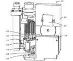
- FIG. FIG. 3 is an explanatory diagram illustrating an outline of the mounting head unit 20.
- FIG. 3 is an explanatory diagram of a positive pressure path 31 and a negative pressure path 41 of the mounting head unit 20.
- FIG. Explanatory drawing of the primary pressure-reduction part 33 and the 2nd vertical motion motor 52.
- FIG. Explanatory drawing of the arrangement position of the decompression part 30 and the drive part 50.
- FIG. 1 is a schematic explanatory diagram illustrating an example of the mounting system 10.
- FIG. 2 is an explanatory diagram showing an outline of the mounting head unit 20.
- FIG. 3 is an explanatory diagram of the positive pressure path 31 and the negative pressure path 41 of the mounting head unit 20.
- FIG. 4 is an explanatory diagram of the rotary unit 22 and the first switching motor 53.
- FIG. 5 is an explanatory diagram of the primary pressure reducing unit 33 and the second vertical movement motor 52.
- FIG. 6 is an explanatory diagram of the arrangement positions of the decompression unit 30 and the drive unit 50.
- FIG. 6 is a conceptual diagram of the rotary unit 22 as viewed from above.
- the mounting system 10 is a system that executes a mounting process for mounting components on the board S.
- the mounting system 10 includes a mounting device 11 and a management computer 70.
- FIG. 1 only one mounting apparatus 11 is shown for convenience of explanation.
- the left-right direction (X-axis), the front-rear direction (Y-axis), and the up-down direction (Z-axis) are as shown in FIG.
- the mounting apparatus 11 includes a board transport unit 12, a component supply unit 14, a positive pressure supply unit 15, a negative pressure supply unit 16, a control unit 17, a mounting head unit 20, and the like. It has.
- the substrate transport unit 12 is a unit that carries in, transports, fixes and unloads the substrate S at the mounting position.
- the substrate transport unit 12 has a pair of conveyor belts provided at intervals in the front-rear direction of FIG. 1 and spanned in the left-right direction. The board
- substrate S is conveyed by this conveyor belt.
- the component supply unit 14 includes a plurality of reels and is detachably attached to the front side of the mounting apparatus 11. A tape is wound around each reel, and a plurality of parts are held on the surface of the tape along the longitudinal direction of the tape. The tape is unwound from the reel toward the rear, and is sent out to a collection position where the tape is collected by the suction nozzle 24 with the components exposed.
- the positive pressure supply unit 15 supplies pressurized air (for example, 500 kPa) to each unit of the mounting apparatus 11, and includes, for example, a pressure pump.
- the positive pressure supply unit 15 supplies pressurized air to the suction nozzle 24 of the mounting head unit 20 via the positive pressure path 31.
- the negative pressure supply unit 16 supplies a negative pressure (for example, 50 Pa or the like) to each unit of the mounting apparatus 11, and is configured by, for example, a decompression pump.
- the negative pressure supply unit 16 supplies a negative pressure to the suction nozzle 24 of the mounting head unit 20 via the negative pressure path 41.
- the positive pressure supply unit 15 and the negative pressure supply unit 16 supply positive pressure and negative pressure to units other than the mounting head unit 20 such as driving of an actuator (air cylinder or the like). Therefore, in the mounting apparatus 11, the positive pressure supply unit 15 supplies high-pressure positive pressure air, and the mounting head unit 20 uses the positive pressure air decompressed by the decompression unit 30.
- the control unit 17 controls the entire mounting apparatus 11 and is configured as a microprocessor centered on the CPU 18 as shown in FIG.
- the control unit 17 outputs control signals to the substrate transport unit 12, the component supply unit 14, the positive pressure supply unit 15, the negative pressure supply unit 16, and the mounting head unit 20. Input the signal.
- the mounting head unit 20 is mounted with a suction nozzle 24 that collects and arranges components by pressure, collects components from the component supply unit 14, and performs a mounting process of arranging the components on the substrate S fixed to the substrate transport unit 12. is there.
- the mounting head unit 20 is moved in the XY directions by driving the head moving unit.
- the mounting head unit 20 includes a bulkhead 21 having an in-head supply unit 25 that supplies components inside the unit.
- the bulkhead 21 is configured as a rotary type mounting head held by the head in a rotatable state.
- the bulkhead 21 includes a rotary unit 22, an in-head supply unit 25, a decompression unit 30, a positive pressure path 31, a negative pressure path 41, and a drive unit 50. Since details of the configuration of the bulkhead and its driving method are detailed in the pamphlet of International Publication No. 2014/136231, detailed description thereof is omitted here.
- the rotary unit 22 is a cylindrical member that is mounted with a plurality of suction nozzles 24 and is driven to rotate.
- the rotary unit 22 is supported by the bulkhead 21 so as to be rotatable about the shaft, and a plurality of nozzle holders 23 (for example, 12 pieces) are arranged on the outer peripheral side thereof.
- the nozzle holder 23 is a long cylindrical member to which the suction nozzle 24 can be attached and detached at the lower end, and is supported by the rotary unit 22 so as to be movable up and down and rotatable.
- the suction nozzle 24 uses pressure to suck a component at the nozzle tip or release a component sucked at the nozzle tip.
- the suction nozzles 24A to 24L are mounted on the rotary unit 22 (see FIG. 6).
- the suction nozzles 24A to 24L are collectively referred to as the suction nozzle 24.
- the position of the suction nozzle 24 ⁇ / b> A in FIG. 6 is a mounting raising / lowering position for picking up the components from the component supply unit 14 and mounting the components on the board S
- the position of the suction nozzle 24 ⁇ / b> E is the head This is the part receiving position where the parts are collected from the inner supply unit 25.
- the rotary unit 22 has switching valves 42A to 42L for switching the pressure of the suction nozzle 24 to any one of negative pressure, atmospheric pressure, and positive pressure, corresponding to the suction nozzles 24A to 24L.
- the switching valves 42A to 42L hook-shaped engaged portions 43A to 43L that are engaged with the engaging portions 55 and 56 (see FIGS. 2 to 4) are disposed.
- holes 38 A to 38 L for discharging positive pressure air to the outside are provided at positions corresponding to the suction nozzles 24.
- the switching valves 42A to 42L, the engaged portions 43A to 43L, and the tearing holes 38A to 38L are also collectively referred to as the switching valve 42, the engaged portion 43, and the tearing hole 38, respectively.
- the tearing hole 38 is a hole for releasing a part of positive pressure air generated when the positive pressure supplied for vacuum breakage of the suction nozzle 24 is reduced.
- the tearing hole 38 is an opening provided to face the drive unit 50 (the first switching motor 53 and the second switching motor 54).
- the drive unit 50 is cooled by positive pressure air discharged from the tear hole 38.
- the in-head supply unit 25 includes a bulk feeder 26, a supply motor 27, and a component supply port 28.
- the in-head supply unit 25 includes a reel on which a tape having components arranged at equal intervals is wound.
- the bulk feeder 26 feeds the tape to the component supply port 28 by driving the supply motor 27.
- a component supply port 28 is disposed below the position of the suction nozzle 24E (component receiving position) in FIG. For this reason, in the mounting head unit 20, the suction nozzle 24 can extract components from the in-head supply unit 25 without moving in the XY directions.
- the mounting head unit 20 includes a positive pressure path 31 and a negative pressure path 41 used for driving the suction nozzle 24.
- the negative pressure path 41 is a pipe that applies the negative pressure supplied from the negative pressure supply unit 16 to the switching valve 42 disposed in the rotary unit 22.
- the positive pressure path 31 is a pipe that is provided with a decompression unit 30 and that supplies positive pressure air that has been supplied from the positive pressure supply unit 15 and then decompressed by the decompression unit 30 to the suction nozzle 24.
- a solenoid valve 32 and a solenoid valve 36 are disposed in the positive pressure path 31.
- the solenoid valve 32 is a valve that is provided in a path for supplying positive pressure air of the supply pressure directly from the positive pressure supply unit 15 to the switching valve 42 and performs supply and stop of supply of the positive pressure air. For example, the solenoid valve 32 is opened when the suction nozzle 24 is cleaned.
- the solenoid valve 36 is disposed in a path for supplying positive pressure air (for example, 200 kPa) primarily reduced from a supply pressure (for example, 500 kPa) to the switching valve 42 via the pressure reducing unit 30 (primary pressure reducing unit 33). ing.
- the solenoid valve 36 is a valve that performs supply and stop of supply of positive-pressure air that has undergone primary pressure reduction. The solenoid valve 36 is always opened during the mounting process of the mounting apparatus 11 and supplies positive pressure air to the switching valve 42 side.
- the decompression unit 30 leaks the supplied positive pressure air to reduce the pressure.
- the first decompression unit 33 performs primary decompression from the supply pressure, and the second decompression performs secondary decompression of the positive pressure air after the primary decompression. Part 37.
- the decompression unit 30 has an opening facing the drive unit 50 and cools the drive unit 50 with leaked positive pressure air.
- the first decompression unit 33 includes a decompression valve 34 that decompresses the supplied positive pressure air and an exhaust port 35 that is an opening that leaks the positive pressure air.
- the first pressure reducing unit 33 always discharges leaking positive pressure air from the exhaust port 35 during operation of the positive pressure supply unit 15. As shown in FIG.
- the first pressure reducing unit 33 is disposed on the main body side of the bulkhead 21, but the exhaust port 35 is opened facing the second vertical movement motor 52.
- the second decompression unit 37 is constituted by a tear hole 38 disposed in the rotary unit 22.
- the end path of the positive pressure path 31 is connected to each of the suction nozzles 24A to 24L via the switching valves 42A to 42L.
- the tear hole 38 of the second pressure reducing unit 37 is provided at the tip of the end path of the positive pressure path 31 connected to each of the suction nozzles 24A to 24L.
- the tear holes 38 are respectively arranged on the outer peripheral surface of the rotary unit 22 at equal intervals at positions corresponding to the positions where the suction nozzles 24A to 24L are arranged.
- the suction nozzle 24 needs a weak positive pressure that cancels the negative pressure and does not fly the parts. For this reason, the opening area of the tear hole 38 is adjusted so that positive pressure air of an appropriate pressure is supplied to the switching valve 42.
- the rotary part 22 has a positive pressure path 31 formed at the axial center thereof, and the end path of the positive pressure path 31 is formed radially from the axial center.
- a communication control member 39 is disposed at the axial center of the rotary unit 22.
- the communication control member 39 is a member that supplies positive pressure air only to the switching valve 42 corresponding to the position where the suction nozzle 24A is moved up and down.
- the communication control member 39 has a cylindrical shape with a notch, and is fixed from below so that the shaft cannot rotate.
- the outer peripheral surface abuts on the inner peripheral surface of the positive pressure path 31 in a portion not having a notch and closes the end path formed at the end thereof, whereas the communication control member 39 communicates with the end path in a portion having a notch. Then, positive pressure air is circulated through this.
- the communication control member 39 supplies positive pressure air to the suction nozzles 24A to 24D. 6 shows the end path of the positive pressure path 31, the end path of the negative pressure path 41 (not shown) is formed below the end path.
- the driving unit 50 includes various motors that supply driving force used for the mounting process.
- the drive unit 50 includes a first vertical movement motor 51, a second vertical movement motor 52, a first switching motor 53, a second switching motor 54, a nozzle rotation motor 57, a rotary unit rotation motor 58, and the like.
- the first vertical movement motor 51 is a motor that engages with the upper end portion of the nozzle holder 23 and moves the suction nozzle 24 ⁇ / b> A up and down at the mounting elevation position.
- the second vertical movement motor 52 is a motor that engages with the upper end portion of the nozzle holder 23 and moves the suction nozzle 24 ⁇ / b> E that collects a component from the in-head supply unit 25 in the mounting head unit 20 at the component receiving position.
- the first switching motor 53 is a motor that moves the engaged portion 43A up and down by engaging the engaging portion 55 with the engaged portion 43A at the mounting elevation position.
- the switching valve 42 ⁇ / b> A switches between negative pressure and positive pressure by driving the first switching motor 53.
- the first switching motor 53 is disposed at a position facing the tear hole 38A (see FIGS. 4 and 6).
- the second switching motor 54 is a motor that moves the engaged portion 43E up and down by engaging the engaging portion 56 with the engaged portion 43E at the component receiving position.
- the switching valve 42E switches from positive pressure (or atmospheric pressure) to negative pressure by driving the second switching motor 54.
- the second switching motor 54 is disposed at a position facing the tear hole 38D (see FIG. 6).
- the nozzle rotation motor 57 is a motor that rotates the suction nozzle 24 by rotating the nozzle holder 23 through a gear.
- the rotary unit rotation motor 58 is a motor that rotates the rotary unit 22 through a gear.
- the first vertical movement motor 51, the second vertical movement motor 52, the nozzle rotation motor 57, the rotary unit rotation motor 58, and the like are disposed above the rotary unit 22.
- the CPU 18 of the control unit 17 drives the positive pressure supply unit 15 and the negative pressure supply unit 16 and opens the solenoid valve 36. Then, a part of the positive pressure air supplied to the positive pressure path 31 is decompressed by the first decompression unit 33 and discharged toward the second vertical movement motor 52 through the exhaust port 35. Further, the positive pressure air supplied to the positive pressure path 31 is partially discharged to the first switching motor 53 and the second switching motor 54 through the tear hole 38 after being decompressed by the second decompression unit 37. .
- the mounting head unit 20 effectively uses a positive pressure air that is always used for vacuum breakage required by the suction nozzle 24 and is discharged by regulating the pressure, and a second vertical movement motor 52, a second switching motor 54, The first switching motor 53 is air-cooled.
- the drive unit 50 of this embodiment corresponds to a drive unit
- the decompression unit 30 corresponds to a decompression unit
- the exhaust port 35 and the tear hole 38 correspond to an opening
- the positive pressure path 31 corresponds to a positive pressure path.
- the positive pressure air corresponds to the positive pressure fluid.
- the mounting head unit 20 of the present embodiment described above drives the leaked positive pressure air from the exhaust port 35 or the tear hole 38 (opening portion) when reducing the positive pressure air supplied to the suction nozzle 24.
- the drive unit 50 is cooled by discharging toward the unit 50 (the second vertical movement motor 52, the first switching motor 53, and the second switching motor 54). In this unit, the positive pressure air to be discarded can be effectively used, and the drive unit 50 can be cooled with a simple configuration without providing a new blower. Further, since the positive pressure air supplied to the suction nozzle 24 is relatively stably supplied to the suction nozzle 24 during the mounting process, and the supply amount is less likely to vary depending on the processing content, this unit has a more stable driving unit. 50 coolings can be performed.
- the mounting head unit 20 has the positive pressure passages 31 connected to the respective suction nozzles 24 at the ends thereof, and the decompression units 30 are respectively provided in the positive pressure passages 31 connected to the respective suction nozzles 24.
- the tear holes 38 are respectively disposed on the outer peripheral surface of the rotary unit 22 corresponding to the positions of the suction nozzles 24. In this unit, it is possible to cool the drive unit 50 arranged to face the outer peripheral surface of the rotary unit 22.
- the rotary unit 22 supplies positive pressure air to the tear hole 38 corresponding to the position of the suction nozzle 24 to be moved up and down, and the drive unit 50 is disposed at a position facing the suction nozzle 24 to be moved up and down.
- a drive unit 50 that drives the suction nozzle 24 is disposed.
- produces heat by using by adsorption
- the mounting head unit 20 includes an in-head supply unit 25 for causing the second vertical movement motor 52 and the second switching motor 54 used when driving the in-head supply unit 25 to release positive pressure air at the time of pressure reduction.
- the driving unit 50 is driven without moving, and the driving unit 50 in which it is difficult to obtain an air cooling effect due to the movement of the mounting head unit 20 can be efficiently cooled.
- the plurality of driving units 50 are efficiently and sufficiently stably cooled by using the positive pressure air leaked by the first pressure reduction unit 33 and the positive pressure air leaked by the second pressure reduction unit 37. It can be performed. Further, in the mounting head unit 20, since the tear hole 38 of the second decompression unit 37 is disposed on the outer peripheral surface of the rotary unit 22, the mounting head unit 20 is used in the suction operation and is disposed near the rotary unit 22. The first switching motor 53 and the second switching motor 54 can be efficiently cooled. Furthermore, sufficiently stable cooling of the drive unit can be performed by using the fluid leaked by the primary decompression and the fluid leaked by the secondary decompression.
- the tear hole 38 is provided at the end of the positive pressure path 31 in the rotary unit 22, positive pressure air is supplied to the first switching motor 53 and the second switching motor 54 through a relatively short path. Can be released.
- the arrangement position of the driving unit 50 is devised, and for example, the second vertical movement motor 52 is disposed in the vicinity of the pressure reducing valve 34. Positive pressure air can be discharged to 52.
- the first pressure reducing unit 33 cools the second vertical movement motor 52 and the second pressure reducing unit 37 cools the first switching motor 53 and the second switching motor 54.
- the first decompression unit 33 and the second decompression unit 37 may cool any one or more motors included in the drive unit 50.
- the drive unit 50 is cooled by the first decompression unit 33 and the second decompression unit 37.
- either one of the cooling units may be omitted or another decompression unit such as a third decompression unit may be omitted.
- the drive unit 50 may be cooled using positive pressure air discharged from the unit.
- the drive unit 50 that drives the suction nozzle 24 is described as being air-cooled by the decompression unit 30, but the drive unit used for the mounting process is not particularly limited as long as the drive unit is air-cooled.
- the supply motor 27 of the in-head supply unit 25 may be air-cooled by the decompression unit 30.
- this mounting head unit it is possible to cool the drive unit used for mounting processing more stably by using a simple configuration.
- the mounting head unit 20 including the in-head supply unit 25 has been described.
- the in-head supply unit 25 may not be provided. Even in a mounting head unit that does not include the in-head supply unit 25, it is highly meaningful to use the present invention because it is necessary to take measures against heat dissipation by speeding up the mounting process.
- the mounting head unit 20 includes the rotary unit 22, but is not particularly limited thereto, and may not be a rotary type. Even in a mounting head unit that is not a rotary type, a drive unit such as a vertical movement motor that moves the suction nozzle 24 up and down is provided. Therefore, by using positive pressure air discharged from the pressure reduction unit 30, a simple configuration can be used. The drive unit can be cooled stably.
- the mounting head unit 20 is mounted with 12 suction nozzles 24, but is not particularly limited as long as one or more suction nozzles 24 are mounted.
- the mounting apparatus 11 including the mounting head unit 20 has been described.
- the present invention is not particularly limited thereto, and the mounting head unit 20 may be used.
- the present invention can be used in the field of mounting electronic components.
Landscapes
- Engineering & Computer Science (AREA)
- Manufacturing & Machinery (AREA)
- Microelectronics & Electronic Packaging (AREA)
- Robotics (AREA)
- Mechanical Engineering (AREA)
- Supply And Installment Of Electrical Components (AREA)
- Manipulator (AREA)
Abstract
本発明の実装ヘッドユニット20は、圧力により部品を採取、配置する吸着ノズル24を装着し部品を実装する実装処理を行うものである。この実装ヘッドユニット20は、実装処理に用いられる駆動力を供給する駆動部50と、駆動部50に対向する開口部を有し、供給された正圧流体をリークさせて減圧し、リークさせた正圧流体により駆動部50を冷却する減圧部30と、減圧部30が配設され減圧部30により減圧された正圧流体を吸着ノズル24に供給する正圧経路31とを備えている。
Description
本発明は、実装ヘッドユニット及び実装装置に関する。
従来、部品を基板に実装処理する実装装置としては、吸着ノズルへ負圧を供給する真空発生装置の排気空気を、吸着ノズルを駆動する駆動部へ向けて吐出させ、駆動部を冷却するものが提案されている(例えば、特許文献1参照)。この実装装置では、格別な冷却駆動手段を必要とせず、全体の小型化を図ることができるとしている。また、実装装置としては、エジェクタ(空気圧機器)への給気が第1及び第2のモータ(アクチュエータ)を空冷するようにしたものが提案されている(例えば、特許文献2参照)。この実装装置では、電子部品を高精度で搭載でき、低コストでコンパクトな実装装置を提供することができるとしている。
しかしながら、この特許文献1に記載された実装装置では、負圧を生じる真空発生装置の排気を用いるものであるが、例えば、装置内の真空度が高い状態で維持された場合などには、排気量が少なくなり駆動部の冷却を十分行うことができない場合があった。また、特許文献2に記載された実装装置では、エジェクタを使用するときに駆動部を冷却することができるが、エジェクタを使用しない場合には駆動部の冷却を十分に行うことができない場合があった。
本発明は、このような課題に鑑みなされたものであり、簡素な構成を用いてより安定して駆動部を冷却することができる実装ヘッドユニット及び実装装置を提供することを主目的とする。
本発明は、上述の主目的を達成するために以下の手段を採った。
本発明の実装ヘッドユニットは、
圧力により部品を採取、配置する吸着ノズルを装着し部品を実装する実装処理を行う実装ヘッドユニットであって、
実装処理に用いられる駆動力を供給する駆動部と、
前記駆動部に対向する開口部を有し、供給された正圧流体をリークさせて減圧し、前記リークさせた正圧流体により該駆動部を冷却する減圧部と、
前記減圧部が配設され前記減圧部により減圧された正圧流体を前記吸着ノズルに供給する正圧経路と、
を備えたものである。
圧力により部品を採取、配置する吸着ノズルを装着し部品を実装する実装処理を行う実装ヘッドユニットであって、
実装処理に用いられる駆動力を供給する駆動部と、
前記駆動部に対向する開口部を有し、供給された正圧流体をリークさせて減圧し、前記リークさせた正圧流体により該駆動部を冷却する減圧部と、
前記減圧部が配設され前記減圧部により減圧された正圧流体を前記吸着ノズルに供給する正圧経路と、
を備えたものである。
このユニットでは、吸着ノズルに供給する正圧流体を減圧する際に、リークさせた正圧流体を開口部から駆動部に向かって放出させることによって駆動部の冷却を行う。このユニットでは、廃棄されるリーク流体を有効利用し、新たな送風装置などを設けることなく、簡素な構成で駆動部の冷却を行うことができる。また、吸着ノズルへ供給する正圧流体は、実装処理中に比較的安定して吸着ノズルへ供給され、処理内容などにより供給量が変動しにくいため、このユニットでは、より安定した駆動部の冷却を行うことができる。ここで、「正圧流体」は、常圧以上の圧力のガスであるものとしてもよく、加圧空気などが挙げられる。
本発明の実装ヘッドユニットは、複数の前記吸着ノズルを装着し回転駆動される円筒部材であるロータリー部、を備え、前記正圧経路は、その末端が各々の前記吸着ノズルに接続されており、前記減圧部は、各々の前記吸着ノズルに接続された前記正圧経路に各々設けられており、前記開口部が前記吸着ノズルの配置位置に対応して前記ロータリー部の外周面に各々配設されているものとしてもよい。このユニットでは、ロータリー部の外周面に対向して配置された駆動部の冷却を行うことができる。
ロータリー部を備えた実装ヘッドユニットにおいて、前記ロータリー部は、上下動させる前記吸着ノズルの配置位置に対応した前記減圧部へ前記正圧流体を供給し、前記駆動部は、前記上下動させる前記吸着ノズルに対向する位置に配設されているものとしてもよい。上下動させる吸着ノズルの近傍には、その吸着ノズルを駆動する駆動部が配置されるため、このユニットでは、吸着動作で用いられることにより発熱する駆動部を効率よく冷却することができる。このユニットにおいて、上下動させる前記吸着ノズルの配置位置に対応した前記減圧部へ前記正圧流体を供給する連通制御部材を有するものとしてもよい。
ロータリー部を備えた実装ヘッドユニットは、部品を供給する供給部、を備え、前記駆動部は、実装処理で前記吸着ノズルを上下動させる第1上下動モータと、実装ヘッドユニット内で前記供給部から部品を採取する吸着ノズルを上下動させる第2上下動モータと、前記吸着ノズルへ供給する圧力を切り替える切替モータと、を含み、前記減圧部は、前記第1上下動モータ、前記第2上下動モータ及び前記切替モータのうち少なくとも1つに対向する前記開口部を有するものとしてもよい。ユニット内に供給部を備える実装ヘッドユニットでは、外部の供給部へ部品を取りに行くなどの長距離の移動がほとんどないことから、移動による空冷効果が得られにくい。したがって、このユニットでは、吸着ノズルへ供給する正圧流体のうち、リークした流体を利用することによって安定した駆動部の冷却を行うことができる。また、このユニットでは、上下動モータや切替モータなどを冷却することができる。
ロータリー部を備えた実装ヘッドユニットにおいて、前記減圧部は、供給圧から一次減圧をする第1減圧部と一次減圧後の正圧流体を二次減圧する第2減圧部とを含み、前記第2減圧部の前記開口部が前記ロータリー部の外周面に配設されているものとしてもよい。このユニットでは、一次減圧でリークした流体と、二次減圧でリークした流体とを利用することによって、十分安定した駆動部の冷却を行うことができる。
本発明の実装ヘッドユニットにおいて、前記駆動部は、少なくとも第1駆動モータと第2駆動モータとを含み、前記減圧部は、供給圧から一次減圧をする第1減圧部と一次減圧後の正圧流体を二次減圧する第2減圧部とを含み、前記第1減圧部により前記第1駆動モータを冷却し、前記第2減圧部により前記第2駆動モータを冷却するものとしてもよい。このユニットでは、一次減圧でリークした流体と、二次減圧でリークした流体とを利用することによって、十分安定した駆動部の冷却を行うことができる。ここで、前記駆動部は、例えば、前記吸着ノズルを上下動させる上下動モータ、前記吸着ノズルへの正圧及び負圧の供給を切り替える切替モータ、前記吸着ノズルを回転させるノズル回転モータ、複数の吸着ノズルを装着した円筒部材であるロータリー部を回転させるロータリー部回転モータのうちいずれか1以上を含み、前記減圧部は、上記モータのうちいずれか1以上を空冷するものとしてもよい。
本発明の実装装置は、上述したいずれかに記載の実装ヘッドユニットを備えている。この実装装置では、簡素な構成を用いてより安定して駆動部を冷却することができる。また、この実装装置では上述したいずれかを採用した態様に応じた効果を得ることができる。
本発明の好適な実施形態を図面を参照しながら以下に説明する。図1は、実装システム10の一例を表す概略説明図である。図2は、実装ヘッドユニット20の概略を表す説明図である。図3は、実装ヘッドユニット20の正圧経路31及び負圧経路41の説明図である。図4は、ロータリー部22及び第1切替モータ53の説明図である。図5は、一次減圧部33及び第2上下動モータ52の説明図である。図6は、減圧部30と駆動部50との配置位置の説明図である。図6は、ロータリー部22を上方から見た概念図である。実装システム10は、部品を基板Sに実装する実装処理を実行するシステムである。この実装システム10は、実装装置11と、管理コンピュータ70とを備えている。図1では、説明の便宜のため実装装置11を1台のみ示している。なお、本実施形態において、左右方向(X軸)、前後方向(Y軸)及び上下方向(Z軸)は図1に示した通りとする。
実装装置11は、図1~6に示すように、基板搬送ユニット12と、部品供給ユニット14と、正圧供給部15と、負圧供給部16と、制御ユニット17と、実装ヘッドユニット20とを備えている。基板搬送ユニット12は、基板Sの搬入、搬送、実装位置での固定、搬出を行うユニットである。基板搬送ユニット12は、図1の前後に間隔を開けて設けられ左右方向に架け渡された1対のコンベアベルトを有している。基板Sはこのコンベアベルトにより搬送される。
部品供給ユニット14は、複数のリールを備え、実装装置11の前側に着脱可能に取り付けられている。各リールには、テープが巻き付けられ、テープの表面には、複数の部品がテープの長手方向に沿って保持されている。このテープは、リールから後方に向かって巻きほどかれ、部品が露出した状態で、吸着ノズル24で採取される採取位置に送り出される。
正圧供給部15は、実装装置11の各ユニットへ加圧した空気(例えば500kPaなど)を供給するものであり、例えば加圧ポンプなどにより構成されている。この正圧供給部15は、例えば、実装ヘッドユニット20の吸着ノズル24へ正圧経路31を介して加圧した空気を供給する。負圧供給部16は、実装装置11の各ユニットへ負圧(例えば50Paなど)を供給するものであり、例えば減圧ポンプなどにより構成されている。この負圧供給部16は、例えば、実装ヘッドユニット20の吸着ノズル24へ負圧経路41を介して負圧を供給する。なお、正圧供給部15や負圧供給部16は、例えばアクチュエータ(エアシリンダなど)の駆動など、実装ヘッドユニット20以外のユニットへも正圧や負圧を供給する。このため、実装装置11において、正圧供給部15では高い圧力の正圧空気を供給し、実装ヘッドユニット20では減圧部30により減圧した正圧空気を利用する。
制御ユニット17は、実装装置11全体の制御を司るものであり、図1に示すように、CPU18を中心とするマイクロプロセッサとして構成されている。この制御ユニット17は、基板搬送ユニット12、部品供給ユニット14、正圧供給部15、負圧供給部16及び実装ヘッドユニット20へ制御信号を出力し、部品供給ユニット14や実装ヘッドユニット20からの信号を入力する。
実装ヘッドユニット20は、圧力により部品を採取、配置する吸着ノズル24を装着し、部品供給ユニット14から部品を採取し、基板搬送ユニット12に固定された基板Sへ配置する実装処理を行うものである。実装ヘッドユニット20は、ヘッド移動ユニットの駆動により、XY方向に移動される。実装ヘッドユニット20は、ユニット内部に部品を供給するヘッド内供給部25を有するバルクヘッド21を備えている。このバルクヘッド21は、回転可能な状態でヘッドに保持されるロータリー型の実装ヘッドとして構成されている。このバルクヘッド21は、ロータリー部22と、ヘッド内供給部25と、減圧部30と、正圧経路31と、負圧経路41と、駆動部50とを備えている。なお、バルクヘッドの構成やその駆動方式などの詳細は、国際公開第2014/136231号パンフレットに詳しいため、ここではその詳細な説明は省略する。
ロータリー部22は、複数の吸着ノズル24を装着し回転駆動される円筒部材である。このロータリー部22は、軸回転可能にバルクヘッド21に支持され、複数のノズルホルダ23(例えば12個)をその外周側に配設している。ノズルホルダ23は、その下端に吸着ノズル24を装着、取外し可能な長尺円筒状の部材であり、ロータリー部22に上下動可能且つ回転可能に支持されている。吸着ノズル24は、圧力を利用して、ノズル先端に部品を吸着したり、ノズル先端に吸着している部品を放したりするものである。ここでは、吸着ノズル24A~24Lの12個がロータリー部22に装着されている(図6参照)。なお、ここでは、吸着ノズル24A~24Lを吸着ノズル24と総称する。この実装ヘッドユニット20では、図6の吸着ノズル24Aの位置が、部品供給ユニット14からの部品採取、及び基板Sへの部品の実装を行う実装昇降位置であり、吸着ノズル24Eの位置が、ヘッド内供給部25からの部品の採取を行う部品受取位置である。
ロータリー部22には、図3に示すように、吸着ノズル24の圧力を、負圧、大気圧及び正圧のいずれかに切り替える切替弁42A~42Lが吸着ノズル24A~24Lに対応して配設されている。この切替弁42A~42Lの上部には、係合部55,56(図2~4参照)に係合される鍔状の被係合部43A~43Lが配設されている。また、図4に示すように、ロータリー部22の外周面には、正圧空気を外部へ放出するにがし孔38A~38Lが吸着ノズル24に対応した位置に設けられている。なお、切替弁42A~42L、被係合部43A~43L及びにがし孔38A~38Lについても、それぞれ切替弁42、被係合部43及びにがし孔38と総称する。にがし孔38は、吸着ノズル24の真空破壊用に供給される正圧を減圧する際に生じた一部の正圧空気を外部へ放出する孔である。にがし孔38は、駆動部50(第1切替モータ53や第2切替モータ54)に対向して設けられる開口部である。駆動部50は、にがし孔38から放出される正圧空気により冷却される。
ヘッド内供給部25は、図2に示すように、バルクフィーダ26と、供給モータ27と、部品供給口28とを備える。ヘッド内供給部25は、部品を等間隔に配置したテープが巻き付けられたリールを内包している。バルクフィーダ26は、供給モータ27の駆動により、テープを部品供給口28へ送り出す。実装ヘッドユニット20では、図6の吸着ノズル24Eの位置(部品受取位置)の下方に部品供給口28が配設されている。このため、実装ヘッドユニット20では、XY方向に移動することなく、吸着ノズル24がヘッド内供給部25から部品を採取することができる。
実装ヘッドユニット20は、吸着ノズル24の駆動に用いる正圧経路31及び負圧経路41を備えている。負圧経路41は、図3に示すように、負圧供給部16から供給される負圧を、ロータリー部22に配設された切替弁42へ付与する配管である。正圧経路31は、減圧部30が配設されており、正圧供給部15から供給されたのち減圧部30により減圧された正圧空気を吸着ノズル24へ供給する配管である。正圧経路31には、ソレノイドバルブ32とソレノイドバルブ36とが配設されている。ソレノイドバルブ32は、正圧供給部15から切替弁42へ直接、供給圧の正圧空気を供給する経路に配設され、正圧空気の供給及び供給停止を行う弁である。ソレノイドバルブ32は、例えば、吸着ノズル24のクリーニングを行う際に開放される。ソレノイドバルブ36は、減圧部30(一次減圧部33)を介することにより、供給圧(例えば500kPaなど)から一次減圧した正圧空気(例えば200kPaなど)を切替弁42へ供給する経路に配設されている。ソレノイドバルブ36は、一次減圧された正圧空気の供給及び供給停止を行う弁である。このソレノイドバルブ36は、実装装置11の実装処理中は常に開放されて正圧空気を切替弁42側へ供給する。
減圧部30は、供給された正圧空気をリークさせて減圧するものであり、供給圧から一次減圧をする第1減圧部33と、一次減圧後の正圧空気を二次減圧する第2減圧部37とを含む。この減圧部30は、駆動部50に対向する開口部を有し、リークさせた正圧空気により駆動部50を冷却する。第1減圧部33は、供給された正圧空気を減圧する減圧弁34と、正圧空気をリークする開口部である排気口35とにより構成されている。第1減圧部33は、正圧供給部15の稼働中において、リークする正圧空気を常に排気口35から放出する。第1減圧部33は、図5に示すように、バルクヘッド21の本体側に配設されているが、排気口35が第2上下動モータ52に対向して開口している。第2減圧部37は、ロータリー部22に配設されたにがし孔38により構成される。正圧経路31は、図3に示すように、その末端経路が切替弁42A~42Lを介して各々の吸着ノズル24A~24Lに接続されている。第2減圧部37のにがし孔38は、図6に示すように、各々の吸着ノズル24A~24Lに接続された正圧経路31の末端経路の先端に各々設けられている。にがし孔38は、吸着ノズル24A~24Lの配置位置に対応した位置に等間隔でロータリー部22の外周面に各々配設されている。吸着ノズル24は、部品を離す際には、負圧を打ち消し、且つ部品が飛ばない程度の微弱な正圧を要する。このため、にがし孔38は、切替弁42へ適切な圧の正圧空気が供給されるようその開口面積が調整されている。ロータリー部22は、その軸中心に正圧経路31が形成されており、正圧経路31の末端経路がこの軸中心から放射状に形成されている。ロータリー部22の軸中心には、連通制御部材39が配設されている。この連通制御部材39は、上下動させる吸着ノズル24Aの配置位置に対応した切替弁42へのみ正圧空気を供給する部材である。この連通制御部材39は、切欠きのある円柱形状を有し、軸回転不能に下方から固定されている。連通制御部材39は、切欠きのない部分では外周面が正圧経路31の内周面に当接し、その先に形成された末端経路を塞ぐ一方、切欠きのある部分では末端経路と連通し、これに正圧空気を流通させる。ここでは、この連通制御部材39は、吸着ノズル24A~24Dへ正圧空気を供給する。なお、図6では、正圧経路31の末端経路を示したが、この下方に図示しない負圧経路41の末端経路が形成されている。
駆動部50は、実装処理に用いられる駆動力を供給する各種モータを含む。この駆動部50には、第1上下動モータ51、第2上下動モータ52、第1切替モータ53、第2切替モータ54、ノズル回転モータ57及びロータリー部回転モータ58などが含まれる。第1上下動モータ51は、ノズルホルダ23の上端部に係合し、実装昇降位置で吸着ノズル24Aを上下動させるモータである。第2上下動モータ52は、ノズルホルダ23の上端部に係合し、実装ヘッドユニット20内でヘッド内供給部25から部品を採取する吸着ノズル24Eを部品受取位置で上下動させるモータである。第1切替モータ53は、実装昇降位置で係合部55が被係合部43Aに係合し、被係合部43Aを上下動させるモータである。切替弁42Aは、第1切替モータ53の駆動により負圧と正圧とを切り替える。この第1切替モータ53は、にがし孔38Aに対向する位置に配設されている(図4,6参照)。第2切替モータ54は、部品受取位置で係合部56が被係合部43Eに係合し、被係合部43Eを上下動させるモータである。切替弁42Eは、第2切替モータ54の駆動により正圧(又は大気圧)から負圧へ切り替える。この第2切替モータ54は、にがし孔38Dに対向する位置に配設されている(図6参照)。ノズル回転モータ57は、ギアを介してノズルホルダ23を軸回転させることにより吸着ノズル24を軸回転させるモータである。ロータリー部回転モータ58は、ギアを介してロータリー部22を軸回転させるモータである。第1上下動モータ51や第2上下動モータ52、ノズル回転モータ57、ロータリー部回転モータ58などは、ロータリー部22の上方に配設されている。
次に、こうして構成された本実施形態の実装装置11の動作、特に減圧部30による駆動部50の冷却について説明する。実装装置11の実装処理が開始されると、制御ユニット17のCPU18は、正圧供給部15及び負圧供給部16を駆動すると共に、ソレノイドバルブ36を開放する。すると、正圧経路31に供給された正圧空気は、第1減圧部33で減圧された一部が排気口35を介して第2上下動モータ52に向かって放出される。また、正圧経路31に供給された正圧空気は、第2減圧部37で減圧された一部がにがし孔38を介して第1切替モータ53や第2切替モータ54へ放出される。近年は、実装処理の高速化が進み、駆動部50の駆動頻度が高くなっており、駆動部50の放熱が問題となっている。特に、実装ヘッドユニット20にヘッド内供給部25を備えるバルクヘッド21では、部品供給ユニット14まで移動しなくても部品を採取できるため、実装ヘッドユニット20の移動に伴う空冷効果を得られにくい。この実装ヘッドユニット20では、吸着ノズル24で要する真空破壊用の、常時利用される正圧空気のうち調圧で排出させるものを有効利用し、第2上下動モータ52や第2切替モータ54、第1切替モータ53を空冷するのである。
ここで、本実施形態の構成要素と本発明の構成要素との対応関係を明らかにする。本実施形態の駆動部50が駆動部に相当し、減圧部30が減圧部に相当し、排気口35及びにがし孔38が開口部に相当し、正圧経路31が正圧経路に相当し、正圧空気が正圧流体に相当する。
以上説明した本実施形態の実装ヘッドユニット20は、吸着ノズル24に供給する正圧空気を減圧する際に、リークさせた正圧空気を排気口35やにがし孔38(開口部)から駆動部50(第2上下動モータ52、第1切替モータ53、第2切替モータ54)に向かって放出させることによって駆動部50の冷却を行う。このユニットでは、廃棄される正圧空気を有効利用し、新たな送風装置などを設けることなく、簡素な構成で駆動部50の冷却を行うことができる。また、吸着ノズル24へ供給する正圧空気は、実装処理中に比較的安定して吸着ノズル24へ供給され、処理内容などにより供給量が変動しにくいため、このユニットでは、より安定した駆動部50の冷却を行うことができる。また、実装ヘッドユニット20は、正圧経路31の末端が各々の吸着ノズル24に接続されており、減圧部30は、各々の吸着ノズル24に接続された正圧経路31に各々設けられており、にがし孔38が吸着ノズル24の配置位置に対応してロータリー部22の外周面に各々配設されている。このユニットでは、ロータリー部22の外周面に対向して配置された駆動部50の冷却を行うことができる。
また、ロータリー部22は、上下動させる吸着ノズル24の配置位置に対応したにがし孔38へ正圧空気を供給し、駆動部50は、上下動させる吸着ノズル24に対向する位置に配設されている。上下動させる吸着ノズル24の近傍には、その吸着ノズル24を駆動する駆動部50が配置される。このため、このユニットでは、吸着動作で用いられることにより発熱する駆動部50を効率よく冷却することができる。更に、実装ヘッドユニット20は、ヘッド内供給部25を備え、ヘッド内供給部25の駆動時に用いられる第2上下動モータ52や第2切替モータ54などに減圧時の正圧空気を放出させるため、実装ヘッドユニット20が移動せずに駆動され、実装ヘッドユニット20の移動による空冷効果を得られにくい駆動部50を効率よく冷却することができる。
また、実装ヘッドユニット20では、第1減圧部33でリークした正圧空気と、第2減圧部37でリークした正圧空気を用いて複数の駆動部50に対して効率よく、十分安定した冷却を行うことができる。また、実装ヘッドユニット20では、第2減圧部37のにがし孔38がロータリー部22の外周面に配設されているため、吸着動作で利用されロータリー部22の近傍に配設された第1切替モータ53や第2切替モータ54を効率よく冷却することができる。更に、一次減圧でリークした流体と、二次減圧でリークした流体とを利用することによって、十分安定した駆動部の冷却を行うことができる。
更に、実装ヘッドユニット20では、ロータリー部22において、正圧経路31の末端に、にがし孔38を設けるため、比較的短い経路で第1切替モータ53や第2切替モータ54へ正圧空気を放出することができる。また、実装ヘッドユニット20では、駆動部50の配置位置をそれぞれ工夫しており、例えば、減圧弁34の近傍に第2上下動モータ52を配置するため、比較的短い経路で第2上下動モータ52へ正圧空気を放出することができる。
なお、本発明は上述した実施形態に何ら限定されることはなく、本発明の技術的範囲に属する限り種々の態様で実施し得ることはいうまでもない。
例えば、上述した実施形態では、第1減圧部33が第2上下動モータ52を冷却し、第2減圧部37が第1切替モータ53や第2切替モータ54を冷却するものとしたが特にこれに限定されず、第1減圧部33や第2減圧部37が、駆動部50に含まれるいずれか1以上のモータを冷却するものとすればよい。また、第1減圧部33と第2減圧部37の2つにより駆動部50を冷却するものとしたが、いずれか一方の冷却を省略してもよいし、第3減圧部など、他の減圧部で放出される正圧空気を用いて駆動部50を冷却するものとしてもよい。
上述した実施形態では、吸着ノズル24を駆動する駆動部50を減圧部30により空冷するものとして説明したが、実装処理に利用される駆動部を空冷するものとすれば、特にこれに限定されず、例えば、減圧部30によりヘッド内供給部25の供給モータ27を空冷するものとしてもよい。この実装ヘッドユニットにおいても、簡素な構成を用いてより安定して実装処理に利用される駆動部を冷却することができる。
上述した実施形態では、ヘッド内供給部25を備えた実装ヘッドユニット20として説明したが。ヘッド内供給部25を備えないものとしてもよい。ヘッド内供給部25を備えない実装ヘッドユニットにおいても、実装処理の高速化により放熱対策が必要であるため、本発明を利用する意義が高い。
上述した実施形態では、実装ヘッドユニット20は、ロータリー部22を備えるものとしたが、特にこれに限定されず、ロータリー式ではないものとしてもよい。ロータリー式ではない実装ヘッドユニットにおいても、吸着ノズル24を上下動する上下動モータなどの駆動部を備えるため、減圧部30から放出される正圧空気を利用して、簡素な構成を用いてより安定して駆動部を冷却することができる。
上述した実施形態では、実装ヘッドユニット20は、12個の吸着ノズル24を装着するものとしたが、1以上の吸着ノズル24を装着するものとすれば、特にこれに限定されない。
上述した実施形態では、実装ヘッドユニット20を備えた実装装置11として説明したが、特にこれに限定されず、実装ヘッドユニット20としてもよい。
本発明は、電子部品の実装分野に利用可能である。
10 実装システム、11 実装装置、12 基板搬送ユニット、14 部品供給ユニット、15 正圧供給部 16 負圧供給部、17 制御ユニット、18 CPU、20 実装ヘッドユニット、21 バルクヘッド、 22 ロータリー部、23 ノズルホルダ、24,24A~24L 吸着ノズル、25 ヘッド内供給部、26 バルクフィーダ、27 供給モータ、28 部品供給口、30 減圧部、31 正圧経路、32 ソレノイドバルブ、33 第1減圧部、34 減圧弁、35 排気口(開口部)、36 ソレノイドバルブ、37 第2減圧部、38,38A~38L にがし孔(開口部)、39 連通制御部材、41 負圧経路、42,42A~42L 切替弁、43 43A~43L 被係合部、50 駆動部、51 第1上下動モータ、52 第2上下動モータ、53 第1切替モータ、54 第2切替モータ、55 係合部、56 係合部、57 ノズル回転モータ、58 ロータリー部回転モータ、70 管理コンピュータ、S 基板。
Claims (7)
- 圧力により部品を採取、配置する吸着ノズルを装着し部品を実装する実装処理を行う実装ヘッドユニットであって、
実装処理に用いられる駆動力を供給する駆動部と、
前記駆動部に対向する開口部を有し、供給された正圧流体をリークさせて減圧し、前記リークさせた正圧流体により該駆動部を冷却する減圧部と、
前記減圧部が配設され前記減圧部により減圧された正圧流体を前記吸着ノズルに供給する正圧経路と、
を備えた実装ヘッドユニット。 - 請求項1に記載の実装ヘッドユニットであって、
複数の前記吸着ノズルを装着し回転駆動される円筒部材であるロータリー部、を備え、
前記正圧経路は、その末端が各々の前記吸着ノズルに接続されており、
前記減圧部は、各々の前記吸着ノズルに接続された前記正圧経路に各々設けられており、前記開口部が前記吸着ノズルの配置位置に対応して前記ロータリー部の外周面に各々配設されている、実装ヘッドユニット。 - 前記ロータリー部は、上下動させる前記吸着ノズルの配置位置に対応した前記減圧部へ前記正圧流体を供給し、
前記駆動部は、前記上下動させる前記吸着ノズルに対向する位置に配設されている、請求項2に記載の実装ヘッドユニット。 - 請求項2又は3に記載の実装ヘッドユニットであって、
部品を供給する供給部、を備え、
前記駆動部は、実装処理で前記吸着ノズルを上下動させる第1上下動モータと、実装ヘッドユニット内で前記供給部から部品を採取する吸着ノズルを上下動させる第2上下動モータと、前記吸着ノズルへ供給する圧力を切り替える切替モータと、を含み、
前記減圧部は、前記第1上下動モータ、前記第2上下動モータ及び前記切替モータのうち少なくとも1つに対向する前記開口部を有する、実装ヘッドユニット。 - 前記減圧部は、供給圧から一次減圧をする第1減圧部と一次減圧後の正圧流体を二次減圧する第2減圧部とを含み、前記第2減圧部の前記開口部が前記ロータリー部の外周面に配設されている、請求項2~4のいずれか1項に記載の実装ヘッドユニット。
- 前記駆動部は、少なくとも第1駆動モータと第2駆動モータとを含み、
前記減圧部は、供給圧から一次減圧をする第1減圧部と一次減圧後の正圧流体を二次減圧する第2減圧部とを含み、前記第1減圧部により前記第1駆動モータを冷却し、前記第2減圧部により前記第2駆動モータを冷却する、請求項1~5のいずれか1項に記載の実装ヘッドユニット。 - 請求項1~6のいずれか1項に記載の実装ヘッドユニットを備えた、実装装置。
Priority Applications (2)
| Application Number | Priority Date | Filing Date | Title |
|---|---|---|---|
| JP2018505098A JP6689361B2 (ja) | 2016-03-15 | 2016-03-15 | 実装ヘッドユニット及び実装装置 |
| PCT/JP2016/058087 WO2017158712A1 (ja) | 2016-03-15 | 2016-03-15 | 実装ヘッドユニット及び実装装置 |
Applications Claiming Priority (1)
| Application Number | Priority Date | Filing Date | Title |
|---|---|---|---|
| PCT/JP2016/058087 WO2017158712A1 (ja) | 2016-03-15 | 2016-03-15 | 実装ヘッドユニット及び実装装置 |
Publications (1)
| Publication Number | Publication Date |
|---|---|
| WO2017158712A1 true WO2017158712A1 (ja) | 2017-09-21 |
Family
ID=59851142
Family Applications (1)
| Application Number | Title | Priority Date | Filing Date |
|---|---|---|---|
| PCT/JP2016/058087 Ceased WO2017158712A1 (ja) | 2016-03-15 | 2016-03-15 | 実装ヘッドユニット及び実装装置 |
Country Status (2)
| Country | Link |
|---|---|
| JP (1) | JP6689361B2 (ja) |
| WO (1) | WO2017158712A1 (ja) |
Citations (6)
| Publication number | Priority date | Publication date | Assignee | Title |
|---|---|---|---|---|
| JPH07246587A (ja) * | 1994-03-11 | 1995-09-26 | Yaskawa Electric Corp | 多関節形産業用ロボットの冷却構造 |
| JP2002137185A (ja) * | 2000-10-27 | 2002-05-14 | Juki Corp | 電子部品実装機の装着ヘッド |
| JP2003031992A (ja) * | 2001-07-17 | 2003-01-31 | Fuji Mach Mfg Co Ltd | 電気部品載置方法および電気部品載置装置 |
| WO2003049523A1 (de) * | 2001-11-29 | 2003-06-12 | Siemens Aktiengesellschaft | Montagevorrichtung für bauteile mit einem sauggreifer |
| JP2003174289A (ja) * | 2001-12-07 | 2003-06-20 | Juki Corp | 電子部品搭載機 |
| WO2014136231A1 (ja) * | 2013-03-06 | 2014-09-12 | 富士機械製造株式会社 | 電子回路部品装着機 |
-
2016
- 2016-03-15 WO PCT/JP2016/058087 patent/WO2017158712A1/ja not_active Ceased
- 2016-03-15 JP JP2018505098A patent/JP6689361B2/ja active Active
Patent Citations (6)
| Publication number | Priority date | Publication date | Assignee | Title |
|---|---|---|---|---|
| JPH07246587A (ja) * | 1994-03-11 | 1995-09-26 | Yaskawa Electric Corp | 多関節形産業用ロボットの冷却構造 |
| JP2002137185A (ja) * | 2000-10-27 | 2002-05-14 | Juki Corp | 電子部品実装機の装着ヘッド |
| JP2003031992A (ja) * | 2001-07-17 | 2003-01-31 | Fuji Mach Mfg Co Ltd | 電気部品載置方法および電気部品載置装置 |
| WO2003049523A1 (de) * | 2001-11-29 | 2003-06-12 | Siemens Aktiengesellschaft | Montagevorrichtung für bauteile mit einem sauggreifer |
| JP2003174289A (ja) * | 2001-12-07 | 2003-06-20 | Juki Corp | 電子部品搭載機 |
| WO2014136231A1 (ja) * | 2013-03-06 | 2014-09-12 | 富士機械製造株式会社 | 電子回路部品装着機 |
Also Published As
| Publication number | Publication date |
|---|---|
| JP6689361B2 (ja) | 2020-04-28 |
| JPWO2017158712A1 (ja) | 2019-01-17 |
Similar Documents
| Publication | Publication Date | Title |
|---|---|---|
| JP5952129B2 (ja) | 部品搬送用ヘッド、部品吸着用ノズル及び部品実装装置 | |
| WO2017086339A1 (ja) | ワイヤソー装置並びに被加工物の加工方法及び加工装置 | |
| JP6096047B2 (ja) | 切削装置およびパッケージ基板の加工方法 | |
| WO2010001527A1 (ja) | 部品実装関連作業機 | |
| KR20130043041A (ko) | 숏블라스트 장치 | |
| TW201607082A (zh) | 封裝基板之加工方法 | |
| JP5152147B2 (ja) | 部品実装機、部品実装システム及び部品実装方法 | |
| JP6959916B2 (ja) | 電子部品装着機および電子部品切離し方法 | |
| JP2009064929A (ja) | テープフィーダ交換用台車 | |
| CN107263193B (zh) | Pcb上下吸尘分板机 | |
| JP2014042945A (ja) | ワーク保持装置および加工機械 | |
| JP2017024150A (ja) | 基板の加工方法及び加工装置 | |
| JPWO2017158712A1 (ja) | 実装ヘッドユニット及び実装装置 | |
| JP2015002336A (ja) | 切削装置 | |
| JP4901557B2 (ja) | 表面実装機 | |
| CN210389418U (zh) | 一种视觉在线分板机 | |
| KR101447128B1 (ko) | 기판이송장치 | |
| JP4888287B2 (ja) | テープ切断装置及びテープフィーダ交換用台車 | |
| US20230422458A1 (en) | Waste-tape transport device and mounting device | |
| CN107211569B (zh) | 吸嘴、安装装置及元件脱离方法 | |
| JP6356142B2 (ja) | 対基板作業装置及び吐出ヘッド | |
| WO2017090201A1 (ja) | 作業装置 | |
| KR101110321B1 (ko) | 기판분할장치 및 기판분할방법 | |
| TWI610755B (zh) | 磨削裝置及其所適用的半導體條帶硏磨機 | |
| JP2019018263A (ja) | 切断加工装置及び切断加工方法 |
Legal Events
| Date | Code | Title | Description |
|---|---|---|---|
| ENP | Entry into the national phase |
Ref document number: 2018505098 Country of ref document: JP Kind code of ref document: A |
|
| NENP | Non-entry into the national phase |
Ref country code: DE |
|
| 121 | Ep: the epo has been informed by wipo that ep was designated in this application |
Ref document number: 16894336 Country of ref document: EP Kind code of ref document: A1 |
|
| 122 | Ep: pct application non-entry in european phase |
Ref document number: 16894336 Country of ref document: EP Kind code of ref document: A1 |