WO2017154810A1 - 照明装置 - Google Patents
照明装置 Download PDFInfo
- Publication number
- WO2017154810A1 WO2017154810A1 PCT/JP2017/008677 JP2017008677W WO2017154810A1 WO 2017154810 A1 WO2017154810 A1 WO 2017154810A1 JP 2017008677 W JP2017008677 W JP 2017008677W WO 2017154810 A1 WO2017154810 A1 WO 2017154810A1
- Authority
- WO
- WIPO (PCT)
- Prior art keywords
- frame member
- frame
- thermal expansion
- base
- cover member
- Prior art date
- Legal status (The legal status is an assumption and is not a legal conclusion. Google has not performed a legal analysis and makes no representation as to the accuracy of the status listed.)
- Ceased
Links
Images


Classifications
-
- F—MECHANICAL ENGINEERING; LIGHTING; HEATING; WEAPONS; BLASTING
- F21—LIGHTING
- F21S—NON-PORTABLE LIGHTING DEVICES; SYSTEMS THEREOF; VEHICLE LIGHTING DEVICES SPECIALLY ADAPTED FOR VEHICLE EXTERIORS
- F21S2/00—Systems of lighting devices, not provided for in main groups F21S4/00 - F21S10/00 or F21S19/00, e.g. of modular construction
-
- F—MECHANICAL ENGINEERING; LIGHTING; HEATING; WEAPONS; BLASTING
- F21—LIGHTING
- F21V—FUNCTIONAL FEATURES OR DETAILS OF LIGHTING DEVICES OR SYSTEMS THEREOF; STRUCTURAL COMBINATIONS OF LIGHTING DEVICES WITH OTHER ARTICLES, NOT OTHERWISE PROVIDED FOR
- F21V15/00—Protecting lighting devices from damage
- F21V15/01—Housings, e.g. material or assembling of housing parts
Definitions
- the present invention relates to a lighting device installed on a ceiling surface.
- LEDs light emitting diodes
- a long light source mounting substrate in which light emitting elements such as LEDs are linearly mounted is attached to a frame member, and AC (alternating current) is used to drive the LEDs with a DC (direct current) voltage.
- a switching power supply for converting the voltage into a DC voltage and supplying the power is housed in the frame member, and the cover member is also attached to cover the light source mounting substrate and also function as a diffusion part for diffusing the irradiation light.
- An illumination device generally called a base light is known.
- a member made of aluminum or an aluminum alloy is used for the frame member because of its processing advantage and light weight, and a resin excellent in light diffusibility is used for the cover member.
- a thermal expansion phenomenon occurs in which the frame member and the cover member expand due to heat generated from the light source unit (LED substrate).
- LED substrate the light source unit
- This invention is made in view of such a point, and it aims at providing the illuminating device which is not received by the influence by thermal expansion also when arrange
- the present invention is attached to the frame member so as to cover the first metal long frame member provided with a long light source unit and the light source unit.
- a long base member, wherein the frame member is longer than the cover member, and at least one end portion of the frame member has a first space that allows deformation due to thermal expansion of the cover member.
- a second space that is longer than the frame member and allows deformation of the frame member due to thermal expansion at at least one end of the base member.
- An illuminating device provided (invention 1).
- the frame member is longer than the cover member, and at least one end of the frame member is provided with a first space that allows deformation due to thermal expansion of the cover member. Even if the cover member expands in the length direction due to heat generated from the light source unit during use of the lighting device, the first space absorbs the expansion, and the base member is longer than the frame member, and at least the base member Since a second space that allows deformation due to thermal expansion of the frame member is separately provided at one of the end portions, even if the frame member expands in the length direction as well as the cover member, the second space does not By absorbing the expansion, even when a plurality of lighting devices are arranged in close proximity to each other, they are not affected by thermal expansion.
- the cover member is made of resin and the frame member is made of metal, the degree of expansion due to thermal expansion differs between the two, and the cover member has a larger expansion than the frame member. Even if the member is thermally expanded to fill the first space, and the cover member is further thermally expanded to extend the frame member, the second space separately absorbs the expansion of the frame member. Therefore, it is not necessary to provide a particularly wide expansion absorption space only in the cover member.
- the base member is made of the second metal having a smaller coefficient of thermal expansion than the frame member, the base member is hardly thermally expanded by the heat generated from the light source unit, and the entire length of the lighting device is used. It is almost maintained even at times.
- the thermal expansion coefficient of the first metal is 20 to 28 ( ⁇ 10 ⁇ 6 / ° C.), and the thermal expansion coefficient of the second metal is 10 to 12 ( ⁇ 10 ⁇ 6 / ° C.) (Invention 2).
- the 1st end part is provided in the at least any one edge part of the said frame member, and the edge part of the said cover member covers a part of said 1st end part.
- the cover member is attached to the frame member (Invention 3).
- the edge part of a cover member will overlap with a part of 1st end part provided in the edge part of the same side of a frame member, and a frame member is made longer than a cover member.
- the first space provided by doing so is provided on the first end portion. Therefore, even if the frame member is longer than the cover member, there is no gap between the cover member and the frame member in appearance, and the appearance of the lighting device does not deteriorate and the lighting performance does not deteriorate.
- the first end portion is made of resin (Invention 4).
- the appearance of the whole lighting device is not impaired in appearance.
- a second end portion is provided at at least one end portion of the base member, and the end portion of the frame member forms a part of the second end portion. It is preferable that the frame member is attached to the base member so as to cover (Invention 5).
- the edge part of a frame member will overlap with a part of 2nd end part provided in the edge part of the same side of a base member, and a base member is made longer than a frame member.
- the second space provided by doing so is provided on the second end portion. Therefore, even if the base member is made longer than the frame member, there is no gap between the frame member and the base member in appearance, and the appearance of the lighting device is not deteriorated and the lighting performance is not deteriorated.
- the second end portion is made of resin (Invention 6).
- the appearance of the whole lighting device is not impaired in appearance. Further, if the second end portion is made of resin, the side wall surface of the second end portion that contacts the adjacent lighting device can be opened, and wiring can be passed between adjacent lighting devices using the opening. become able to.
- the lighting devices of the present invention are not affected by thermal expansion even when a plurality of lighting devices are arranged closely in a row.
- the lighting device 1 is fixed to an anchor bolt (not shown) extending vertically downward from a building housing (not shown) via a fixing member (not shown) or the like, thereby causing an indoor ceiling surface (not shown). ).
- an anchor bolt not shown
- the lighting device 1 is attached to the ceiling surface on the bottom side, that is, the state in which the lighting device 1 is actually attached to the ceiling surface is upside down. It is drawn in.
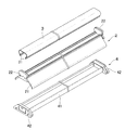
- the illuminating device 1 is accommodated in the elongate frame member 2, the elongate cover member 3 attached to the frame member 2 so as to cover the upper surface side of the frame member 2, and the frame member 2. And a base member 4 attached to the frame member 2 so as to be opposed to the cover member 3 with the frame member 2 interposed therebetween, and an LED mounting board which is a long light source unit mounted on the outer bottom surface of the frame member 2 5 and a switching power supply (not shown) that is housed inside the frame member 2 and supplies driving power to the LEDs.
- the frame member 2 has a trapezoidal shape that is rectangular in plan view and has a trapezoidal shape in a longitudinal cross-sectional view in which the side attached to the ceiling surface (the lower side in FIGS. 2 and 3) is open and the upper surface side is substantially flat.
- Two frame end members 22 are attached to both ends of a frame-shaped frame body 21 by fixing means such as screws.
- a heat sink 211 is formed on the inner surface of the frame main body 21 by standing up a plurality of flat fins.
- a board mounting slot 212 is formed outside the upper surface of the frame body 21 so that the LED mounting board 5 can be inserted by sliding. Further, attachment groove portions 213 for attaching the cover member 3 to the frame member 2 are formed at both ends of the upper surface of the frame body 21.
- the heat sink 211, the board mounting slot 212, and the mounting groove 213 are all formed integrally with the frame body 21.
- the frame main body 21 of the frame member 2 of the present embodiment is manufactured by extrusion molding of an aluminum alloy, and is formed by integrally molding a heat sink 211, a board mounting slot 212, and a mounting groove 213.
- the metal used as the raw material of the frame body 21 is not necessarily limited to an aluminum alloy, and is preferably a metal having a thermal expansion coefficient in the range of 20 to 28 ( ⁇ 10 ⁇ 6 / ° C.), such as a magnesium alloy. Can be used.
- the manufacturing method of the frame main body 21 can also be suitably selected according to the characteristic of the metal used as a raw material.
- the frame end member 22 is located on the outer side when attached to the end of the frame main body 21 and functions as a side wall of the frame member 2. When attached, it is located inside and fits into the end of the frame main body 21, and includes a fitting portion 222 that enters and overlaps the inside of the end of the cover member 3 to be described later.
- the side wall part 221 has a shape in which an elliptical side wall elliptical part 221b is coupled to the upper part of the trapezoidal side wall trapezoidal part 221a.
- the inclined surfaces on both sides of the side wall trapezoidal portion 221a have an inclination angle corresponding to the inclined surfaces extending from the attachment groove portions 213 at both ends of the upper surface of the frame body 21.
- the elliptical shape of the side wall elliptical portion 221 b is a shape corresponding to the elliptical shape of the cover member 3.
- the fitting part 222 has a shape in which an elliptical fitting elliptical part 222b slightly smaller than the side wall elliptical part 221b is coupled to the upper part of the trapezoidal fitting trapezoidal part 222a slightly smaller than the side wall trapezoidal part 221a.
- the inclined surfaces on both sides of the fitting trapezoidal portion 222a have an inclination angle corresponding to the inclined surfaces extending from the mounting grooves 213 at both ends of the upper surface of the frame main body 21. A part of the inclined surface extending from the groove portion 213 is in contact with the inclined surface of the fitting trapezoidal portion 222a.
- the elliptical shape of the fitting elliptical portion 222b is a shape corresponding to the elliptical shape of the cover member 3, and the cover member 3 is such that the end portion of the covering member 3 covers a part of the fitting elliptical portion 222b. Can be attached to the frame member 2.
- the frame end member 22 is manufactured, for example, by injection molding of a resin such as ABS or polycarbonate.
- a resin such as ABS or polycarbonate.
- the cover member 3 is a long resin member that covers the LED mounting substrate 5 and also functions as a diffusion member that diffuses the irradiation light of the LED.
- the cover member 3 is configured such that the attachment claw portions 31 formed on the lower both ends of the cover member 3 are fitted into the attachment groove portions 213 formed on both ends of the upper surface of the frame body 21 of the frame member 2, thereby Attached to.
- the cover member 3 has a C-shaped cross-sectional view in which a lower part (side attached to the frame member 2) of a tube having an elliptical cross section is opened, and can be made of, for example, milky white polycarbonate.
- the base member 4 has a rectangular shape in plan view and a longitudinal sectional view C in which the side attached to the ceiling surface (upper side in FIGS. 2 and 3) is open and the bottom surface side is formed substantially flat.
- Two base end members 42 are attached to both ends of a bowl-shaped long base body 41 having a letter shape by fixing means such as screws.
- a plurality of torsion springs (not shown) for fixing the frame member 2 to the base member 4 are attached to the inside of the base main body 41 at intervals.
- the base body 41 of the base member 4 of the present embodiment is made of iron, and is manufactured by bendering a steel plate or roll forming a rolled steel plate.
- the metal used as the raw material of the base body 41 is not necessarily limited to iron, but may be any metal that has a coefficient of thermal expansion smaller than that of the metal used for the frame body 21 of the frame member 2 and has a coefficient of thermal expansion of 10 to Any metal in the range of 12 ( ⁇ 10 ⁇ 6 / ° C.), for example, stainless steel (SUS400 series) can be suitably used. Further, the manufacturing method of the base body 41 can also be appropriately selected according to the characteristics of the metal used as the raw material.
- the base end member 42 is attached to the end portion of the base body 41 and the side wall portion 421 that functions as the side wall of the base member 4 and is located outside when attached to the end portion of the base body 41. When fitted, it is located inside and fits into the end of the base body 41, and enters into the inside of the end of the frame body 21 of the frame member 2 so as to overlap.
- the side wall portion 421 has a height lower than that of the plate portion 421a, the inclined surfaces on both sides are continuous from the inclined surfaces on both sides of the plate portion 421a, and has the same inclination angle. It has a shape in which Mt. Fuji-shaped block portion 421b is bonded. Further, the fitting portion 422 has the same height as the block portion 421b of the side wall portion 421, but has a Mt. Fuji shape in a side view in which the inclined surfaces on both sides are formed starting from a little closer to the center than the block portion 421b.
- the inclined surfaces on both sides of the plate portion 421a and the block portion 421b of the side wall portion 421 and the fitting portion 422 all have inclination angles corresponding to the inclined surfaces extending from the attachment groove portions 213 on both ends of the upper surface of the frame body 21.
- a part of the inclined surface extending from the attachment groove portions 213 at both ends of the upper surface of the frame body 21 contacts the inclined surface of the fitting portion 422. Touch.
- the base end member 42 is manufactured by, for example, injection molding of a resin such as ABS or polycarbonate.
- a resin such as ABS or polycarbonate.
- the side wall 421 of the base end member 42 is provided with a slit 421c in a substantially rectangular shape, and an opening can be provided in the side wall 421 by pushing a portion surrounded by the slit 421c.
- the base end member 42 is made of resin, the side wall surface of the base end member 42 that comes into contact with another adjacent lighting device can be easily opened when the plurality of lighting devices 1 are arranged in tandem.
- the wiring can be passed between adjacent lighting devices using the opening.
- the LED mounting board 5 is formed by arranging a plurality of LEDs on a long LED board at a predetermined interval, and is slid into a board mounting slot 212 formed on the outer surface of the frame body 21 of the frame member 2. To be installed.
- the LED mounting substrate 5 is merely detachably inserted into the substrate mounting slot 212, and can be easily replaced as necessary.
- a switching power supply (not shown) converts an AC (alternating current) voltage supplied via a power cable (not shown) extending from the ceiling surface into a DC voltage to drive the LED with a DC (direct current) voltage. It is for transmitting power to the mounting substrate 5, accommodated inside the frame member 2, and placed and fixed on the heat sink 211.
- the switching power supply (not shown) may be housed inside the base member 4 and fixed so as to contact the heat sink 211 in a state where the base member 4 is attached to the frame member 2.
- the frame member 2 is formed longer than the cover member 3, and the end of the cover member 3 covers a part of the fitting ellipse 222 b of the frame end member 22 of the frame member 2.
- the cover member 3 is attached to the frame member 2, as shown in FIG. 1, when the cover member 3 is attached to the frame member 2, the cover member 3 is interposed between the end portion of the cover member 3 and the side wall portion 221 of the frame end member 22. still have room, which serves as a first space S 1 that allows the deformation due to thermal expansion of the cover member 3.
- the end of the cover member 3 overlaps with a part of the frame end member 22 provided at the end of the same side of the frame member 2, and the frame member 2 is made longer than the cover member 3.
- the provided first space S 1 is provided on the frame end member 22. Therefore, even if the frame member 2 is made longer than the cover member 3, there is no gap between the cover member 3 and the frame member 2 so that the inside of the lighting device 1 is exposed. Will not deteriorate or the lighting performance will not deteriorate.
- the base member 4 is formed longer than the frame member 2, and the end of the frame member 2 covers a part of the fitting portion 422 of the base end member 42 of the base member 4.
- the frame member 2 is attached to the base member 4. As shown in FIG. 1, when the frame member 2 is attached to the base member 4, the frame member 2 is positioned between the end portion of the frame member 2 and the side wall portion 421 of the base end member 42. still have room, which serves as a second space S 2 to permit deformation due to thermal expansion of the frame member 2 and the cover member 3 in.
- the end of the frame member 2 overlaps with a part of the base end member 42 provided at the end on the same side of the base member 4, and the base member 4 is made longer than the frame member 2.
- the second space S 2 which is provided will be provided on the base end member 42. Therefore, even if the base member 4 is made longer than the frame member 2, there is no gap between the frame member 2 and the base member 4 so that the inside of the lighting device 1 is exposed. Will not deteriorate or the lighting performance will not deteriorate.
- FIG. 6A shows a state before the thermal expansion of the cover member 3 and the frame member 2 due to the heat generated from the light source unit.
- the end of the cover member 3 and the frame end member 22 A first space S 1 allowing deformation due to thermal expansion of the cover member 3 is formed between the side wall 221 and the frame member 2 and the side wall 421 of the base end member 42 between the end of the frame member 2 and the side wall 421.
- the second space S 2 to permit deformation due to thermal expansion of the cover member 3 is in the state respectively provided.
- the LED is used when the lighting device 1 is used. be expanded in the longitudinal direction the cover member 3 by heat generated from the mounting substrate 5, the first space S 1 is to absorb the expansion amount. Specifically, as shown in FIG. 6B, even if the cover member 3 is expanded in the length direction due to heat generated from the LED mounting substrate 5, the end of the cover member 3 is the frame end member 22. the side wall portion 221 to abut the first space S 1 and is filled thermal expansion is allowed.
- the base member 4 is longer than the frame member 2 and the end portion of the base member 4 is separately provided with a second space S 2 that allows deformation of the cover member 3 and the frame member 2 due to thermal expansion.
- the second space S 2 to absorb the expansion amount.
- the frame member 2 is expanded in the length direction due to heat generated from the LED mounting substrate 5, the end of the frame member 3 is the base end member 42. the side wall portion 421 to contact with the second space S 2 is filled thermal expansion is allowed.
- an illumination device 1 of this embodiment the permit deformation due to thermal expansion of the first space S 1 and the cover member 3 and the frame member 2 that allows the deformation due to thermal expansion of the cover member 3 at both ends for 2 space S 2 is provided, there is no influence due to thermal expansion even when arranged in tandem by a plurality closely.
- the cover member 3 is made of resin and the frame member 2 is made of metal, the degree of expansion due to thermal expansion of both is different, and the cover member 3 is larger in expansion than the frame member 2, previously would meet the cover member 3 is a first space S 1 and the thermal expansion, even if the cover member 3 is gone further extended press frame member 2 by thermal expansion, the second space expansion portion of the frame member 2 Since S 2 is separately absorbed, it is not necessary to provide a particularly wide expansion absorption space only in the cover member 3.
- the base member 4 is made of iron having a smaller thermal expansion coefficient than the frame member 2, the base member 4 hardly thermally expands due to the heat generated from the LED mounting substrate 5. Is almost maintained during use.
- the frame end member 22 is attached to both ends of the frame main body 21, and a first space S 1 that allows deformation due to thermal expansion of the cover member 3 is provided at both ends of the frame member 2.
- the frame end member 22 may be provided only at one end of the frame member 2.
- the base end member 42 is attached to both ends of the base main body 41, and the second space S 2 that allows deformation of the cover member 3 and the frame member 2 due to thermal expansion at both ends of the base member 4.
- the present invention is not limited to this.
- the base end member 42 may be provided only at one end of the base member 4.
- the frame end member 22 and the base end member 42 are preferably provided on the same end side.
- space S 2 is ensured thermal expansion absorbing space as go may be a method of providing what kind either, for example, the end frame members 22 provided at the end of the frame member 2 cover member 3 slipped Alternatively, the thermal expansion absorption space may be secured by allowing the frame member 2 to sink into the base end member 42 provided at the end of the base member 4.
- the configuration of the lighting device 1, the shape of the frame member 2, the cover member 3, the base member 4, etc., the LED arrangement on the LED mounting substrate 5, etc. can be freely changed.
Landscapes
- Engineering & Computer Science (AREA)
- General Engineering & Computer Science (AREA)
- Non-Portable Lighting Devices Or Systems Thereof (AREA)
- Arrangement Of Elements, Cooling, Sealing, Or The Like Of Lighting Devices (AREA)
Abstract
照明装置1は、長尺状の光源部5が設けられた、第1の金属製の長尺状のフレーム部材2と、光源部5を覆うようにフレーム部材2に取り付けられる、樹脂製の長尺状のカバー部材3と、フレーム部材2を挟んでカバー部材3に相対するようにフレーム部材2に取り付けられる、第1の金属よりも熱膨張係数が小さい第2の金属製の長尺状のベース部材4と、を備える。フレーム部材2がカバー部材3よりも長く、フレーム部材2の少なくとも何れか一方の端部にカバー部材3の熱膨張による変形を許容する第1スペースS1が設けられており、ベース部材4がフレーム部材2よりも長く、ベース部材4の少なくとも何れか一方の端部にフレーム部材2の熱膨張による変形を許容する第2スペースS2が設けられている。
Description
本発明は天井面に設置される照明装置に関する。
近年、発光ダイオード(LED;Light Emitting Diode)等の発光素子を光源として用いる照明装置が普及している。そのような照明装置として、例えば、複数のLED等の発光素子を線状に実装した長尺状の光源実装基板をフレーム部材に取り付け、LEDをDC(直流)電圧で駆動するためにAC(交流)電圧をDC電圧に変換して電源送給するためのスイッチング電源をフレーム部材内部に収納し、光源実装基板をカバーするとともに照射光を拡散させる拡散部としても機能するカバー部材を取り付けて構成された、一般にベースライトと呼ばれる照明装置が知られている。
従来のベースライトは、フレーム部材には加工優位性や軽量であることを理由にアルミ又はアルミ合金製の部材が用いられ、カバー部材には光拡散性に優れた樹脂が使用されている。このような照明装置を使用する場合、例えば特許文献1に記載されているように、光源部(LED基板)から発生する熱によってフレーム部材及びカバー部材が膨張する熱膨張現象が起きている。例えば2400mmの本体長を有する照明装置の場合、長手方向で3mm程度の膨張幅が認められるが、照明装置を単体で使用するのであればその程度の膨張幅は許容範囲内であり、照明装置の使用上で熱膨張現象が問題になることはなかった。
ところが、最近はドラッグストア等の店内を特に明るく照らす需要がある場所において、照明装置を複数密接させて縦列に配置、すなわち長手方向に並べて配置することが増えている。単独での使用であれば特に熱膨張現象が問題になることはなかったが、複数台の照明装置を密接させて縦列に配置すると、熱膨張による影響が並べた台数分足し合わされることになる。例えば、上述の2400mmの長さの照明装置を10台縦列に並べて配置した場合、熱膨張による長さの増分は全体で30mm(3mm×10台)にもなり、フレーム部材やカバー部材の変形・破損に繋がるおそれがある。
本発明は、このような点に鑑みてなされたものであり、複数密接させて縦列に配置する場合にも、熱膨張による影響を受けることがない照明装置を提供することを目的とする。
上記目的を達成するために、本発明は、長尺状の光源部が設けられた、第1の金属製の長尺状のフレーム部材と、前記光源部を覆うように前記フレーム部材に取り付けられる、樹脂製の長尺状のカバー部材と、前記フレーム部材を挟んで前記カバー部材に相対するように前記フレーム部材に取り付けられる、前記第1の金属よりも熱膨張係数が小さい第2の金属製の長尺状のベース部材と、を備え、前記フレーム部材が前記カバー部材よりも長く、前記フレーム部材の少なくとも何れか一方の端部に前記カバー部材の熱膨張による変形を許容する第1スペースが設けられており、前記ベース部材が前記フレーム部材よりも長く、前記ベース部材の少なくとも何れか一方の端部に前記フレーム部材の熱膨張による変形を許容する第2スペースが設けられている照明装置を提供する(発明1)。
上記発明(発明1)によれば、フレーム部材がカバー部材よりも長く、フレーム部材の少なくとも何れか一方の端部にカバー部材の熱膨張による変形を許容する第1スペースが設けられているため、照明装置の使用時に光源部から発生する熱によってカバー部材が長さ方向に膨張しても、当該第1スペースがその膨張分を吸収し、更にベース部材がフレーム部材よりも長く、ベース部材の少なくとも何れか一方の端部にフレーム部材の熱膨張による変形を許容する第2スペースも別途設けられているため、カバー部材のみならずフレーム部材が長さ方向に膨張しても、当該第2スペースがその膨張分を吸収することにより、照明装置を複数密接させて縦列に配置する場合にも、熱膨張による影響を受けることがない。加えて、カバー部材が樹脂製であり、フレーム部材が金属製であることにより両者の熱膨張による膨張の度合いが異なり、カバー部材の方がフレーム部材よりも膨張分が大きくなるが、先にカバー部材が熱膨張して第1スペースを満たしてしまい、カバー部材が更に熱膨張してフレーム部材を押し延ばしてしまっても、フレーム部材の膨張分を第2スペースが別途吸収する構造となっているため、カバー部材にだけ特別に広い膨張吸収スペースを設ける必要がない。このとき、ベース部材はフレーム部材よりも熱膨張係数が小さい第2の金属製となっているため、光源部から発生する熱によってベース部材が熱膨張することはほとんどなく、照明装置の全長は使用時においてもほぼ維持される。
上記発明(発明1)においては、前記第1の金属の熱膨張係数が20~28(×10-6/℃)であり、前記第2の金属の熱膨張係数が10~12(×10-6/℃)であることが好ましい(発明2)。
上記発明(発明1,2)においては、前記フレーム部材の少なくとも何れか一方の端部に第1エンド部が設けられており、前記カバー部材の端部が前記第1エンド部の一部を覆うように、前記カバー部材が前記フレーム部材に取り付けられていることが好ましい(発明3)。
上記発明(発明3)によれば、カバー部材の端部がフレーム部材の同じ側の端部に設けられている第1エンド部の一部と重なり合うことになり、カバー部材よりもフレーム部材を長くすることにより設けられる第1スペースは第1エンド部上に設けられることになる。したがって、カバー部材よりもフレーム部材を長くしても、外観上カバー部材とフレーム部材との間に隙間ができることはなく、照明装置の見栄えが悪くなることや照明性能が低下することもない。
上記発明(発明3)においては、前記第1エンド部が樹脂製であることが好ましい(発明4)。
上記発明(発明4)によれば、外観上照明装置全体の一体感が損なわれることがない。
上記発明(発明1~4)においては、前記ベース部材の少なくとも何れか一方の端部には第2エンド部が設けられており、前記フレーム部材の端部が前記第2エンド部の一部を覆うように、前記フレーム部材が前記ベース部材に取り付けられていることが好ましい(発明5)。
上記発明(発明5)によれば、フレーム部材の端部がベース部材の同じ側の端部に設けられている第2エンド部の一部と重なり合うことになり、フレーム部材よりもベース部材を長くすることにより設けられる第2スペースは第2エンド部上に設けられることになる。したがって、フレーム部材よりもベース部材を長くしても、外観上フレーム部材とベース部材との間に隙間ができることはなく、照明装置の見栄えが悪くなることや照明性能が低下することもない。
上記発明(発明5)においては、前記第2エンド部が樹脂製であることが好ましい(発明6)。
上記発明(発明6)によれば、外観上照明装置全体の一体感が損なわれることがない。また、第2エンド部が樹脂製であれば、隣接する照明装置に当接する第2エンド部の側壁面を開口させることができ、その開口を用いて隣接する照明装置間に配線を通すことができるようになる。
本発明の照明装置は、複数密接させて縦列に配置する場合にも、熱膨張による影響を受けることがない。
以下、本発明の実施形態を図面に基づいて詳細に説明する。まず最初に、本実施形態に係る照明装置1の構造を、図1~5を参照しながら説明する。照明装置1は、建造物躯体(不図示)から鉛直下方向に延設されたアンカーボルト(不図示)に固定部材(不図示)等を介して固定されることにより室内の天井面(不図示)に取り付けられるものである。なお、図1~5の各図においては、説明の都合上、照明装置1は天井面に取り付けられる側が下になっており、すなわち実際に天井面に照明装置1を取り付けた状態とは天地逆に描かれている。
照明装置1は、長尺状のフレーム部材2と、フレーム部材2の上面側を覆うようにフレーム部材2に取り付けられた長尺状のカバー部材3と、フレーム部材2の内部に収容されるように、かつフレーム部材2を挟んでカバー部材3に相対するようにフレーム部材2に取り付けられたベース部材4と、フレーム部材2の底面外側に装着された長尺状の光源部であるLED実装基板5と、フレーム部材2の内部に収容されてLEDへ駆動電力を供給するスイッチング電源(不図示)から構成されている。
フレーム部材2は、天井面に取り付けられる側(図2及び3における下側)が開放され、上面側が略平坦に形成された、平面視矩形かつ長手方向断面視富士山形の台形状を有する長尺状のフレーム本体21の両端に、ビス止め等の固定手段で二つのフレームエンド部材22を取り付けてなるものである。フレーム本体21の上面内側には、複数枚の平板状フィンを立設してなるヒートシンク211が形成されている。またフレーム本体21の上面外側には、LED実装基板5をスライド挿入して装着可能な基板装着スロット212が形成されている。さらにフレーム本体21の上面両端部には、カバー部材3をフレーム部材2に取り付けるための取付溝部213が形成されている。これらのヒートシンク211、基板装着スロット212及び取付溝部213は、全てがフレーム本体21と一体的に形成されている。
本実施形態のフレーム部材2のフレーム本体21は、アルミニウム合金の押し出し成形加工によって製造されており、ヒートシンク211、基板装着スロット212、取付溝部213を一体成型したものである。フレーム本体21の原材料として用いられる金属は必ずしもアルミニウム合金に限られるものではなく、少なくとも熱膨張係数が20~28(×10-6/℃)の範囲にある金属、例えばマグネシウム合金等であれば好適に用いることができる。またフレーム本体21の製造方法も原材料として用いられる金属の特性に応じて適宜選択することができる。
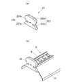
フレームエンド部材22は、図4に示すように、フレーム本体21の端部に取り付けられたときに外側に位置してフレーム部材2の側壁として機能する側壁部221と、フレーム本体21の端部に取り付けられたときに内側に位置してフレーム本体21の端部に嵌合し、後述するカバー部材3の端部の内側に入り込んで重なり合う嵌合部222とからなる。
側壁部221は、台形状の側壁台形部221aの上部に楕円形状の側壁楕円部221bが結合した形状を有する。側壁台形部221aの両側の傾斜面は、フレーム本体21の上面両端部の取付溝部213から延設された傾斜面に対応する傾斜角を有している。また、側壁楕円部221bの楕円形状は、カバー部材3の楕円形状に対応する形状となっている。
嵌合部222は、側壁台形部221aよりもやや小さな台形状の嵌合台形部222aの上部に、側壁楕円部221bよりもやや小さな楕円形状の嵌合楕円部222bが結合した形状を有する。嵌合台形部222aの両側の傾斜面は、フレーム本体21の上面両端部の取付溝部213から延設された傾斜面に対応する傾斜角を有しており、フレーム本体21の上面両端部の取付溝部213から延設された傾斜面の一部が嵌合台形部222aの傾斜面に当接している。また、嵌合楕円部222bの楕円形状は、カバー部材3の楕円形状に対応する形状となっており、カバー部材3の端部が嵌合楕円部222bの一部を覆うように、カバー部材3をフレーム部材2に取り付けることができる。
フレームエンド部材22は、例えばABSやポリカーボネート等の樹脂の射出成形により製造される。フレームエンド部材22を樹脂製とすることにより、各部材を組み合わせて照明装置1を構成した際にも外観上の一体感が損なわれることがない。
カバー部材3は、図2及び3に示すように、LED実装基板5をカバーするとともに、LEDの照射光を拡散させる拡散部材としても機能する樹脂製の長尺状部材である。カバー部材3は、フレーム部材2のフレーム本体21の上面両端に形成された取付溝部213に、カバー部材3の下側両端辺に形成された取付爪部31を嵌合させることによって、フレーム部材2に取り付けられる。カバー部材3は、断面楕円形の管の下部(フレーム部材2に取り付けられる側)が開放された断面視C字形状を有し、例えば乳白色のポリカーボネート製とすることができる。
ベース部材4は、図2及び3に示すように、天井面に取り付けられる側(図2及び3における上側)が開放され、底面側が略平坦に形成された、平面視矩形かつ長手方向断面視C字形状を有する樋形の長尺状のベース本体41の両端に、ビス止め等の固定手段で二つのベースエンド部材42を取り付けてなるものである。ベース本体41内側には、ベース部材4にフレーム部材2を固定するための複数個のトーションばね(不図示)が間隔を空けて取り付けられている。
本実施形態のベース部材4のベース本体41は鉄製であり、鋼板のベンダー加工やロール鋼板のロールフォーミングによって製造される。ベース本体41の原材料として用いられる金属は必ずしも鉄に限られるものではなく、少なくともフレーム部材2のフレーム本体21に用いられる金属よりも熱膨張係数が小さい金属であればよく、熱膨張係数が10~12(×10-6/℃)の範囲にある金属、例えばステンレス鋼(SUS400番台)等であれば好適に用いることができる。またベース本体41の製造方法も原材料として用いられる金属の特性に応じて適宜選択することができる。
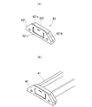
ベースエンド部材42は、図5に示すように、ベース本体41の端部に取り付けられた時に外側に位置してベース部材4の側壁として機能する側壁部421と、ベース本体41の端部に取り付けられた時に内側に位置してベース本体41の端部に嵌合し、フレーム部材2のフレーム本体21の端部の内側に入り込んで重なり合う嵌合部422とからなる。
側壁部421は、側面視富士山形状のプレート部421aに、高さがプレート部421aよりも低く、両側の傾斜面がプレート部421aの両側の傾斜面から連続するとともに同じ傾斜角を有する、側面視富士山形状のブロック部421bが貼り合わされた形状を有する。また、嵌合部422は、高さは側壁部421のブロック部421bと同じだが、両側の傾斜面がブロック部421bよりも少し中心寄りを起点に形成されている、側面視富士山形状を有する。側壁部421のプレート部421a及びブロック部421b、並びに嵌合部422の両側の傾斜面は、いずれもフレーム本体21の上面両端部の取付溝部213から延設された傾斜面に対応する傾斜角を有しており、フレーム部材2にベース部材4を取り付けた状態においては、フレーム本体21の上面両端部の取付溝部213から延設された傾斜面の一部が嵌合部422の傾斜面に当接する。
ベースエンド部材42は、例えばABSやポリカーボネート等の樹脂の射出成形により製造される。ベースエンド部材42を樹脂製とすることにより、各部材を組み合わせて照明装置1を構成した際にも外観上の一体感が損なわれることがない。また、ベースエンド部材42の側壁部421には略矩形状にスリット421cが入れられており、このスリット421cに囲まれた部分を押し込むことにより側壁部421に開口を設けることができる。このようにベースエンド部材42が樹脂製であれば、複数の照明装置1を縦列に並べて配置する際に、隣接する他の照明装置に当接するベースエンド部材42の側壁面を容易に開口させることができ、その開口を用いて隣接する照明装置間に配線を通すことが可能となる。
LED実装基板5は、長尺状のLED基板に複数のLEDを所定の間隔で配列してなるものであり、フレーム部材2のフレーム本体21の上面外側に形成された基板装着スロット212にスライド挿入して装着される。LED実装基板5は基板装着スロット212に着脱自在に挿入されているだけであり、必要に応じて容易に交換可能な構造となっている。
スイッチング電源(不図示)は、LEDをDC(直流)電圧で駆動するために、天井面内部から延びる電源ケーブル(不図示)を経て供給されるAC(交流)電圧をDC電圧に変換し、LED実装基板5へ送電するためのものであり、フレーム部材2の内部に収容され、ヒートシンク211上に載置・固定される。あるいはスイッチング電源(不図示)はベース部材4の内部に収容され、フレーム部材2にベース部材4を取り付けた状態において、ヒートシンク211に当接するように固定されていても良い。
本実施形態においては、フレーム部材2がカバー部材3よりも長く形成されており、カバー部材3の端部がフレーム部材2のフレームエンド部材22の嵌合楕円部222bの一部を覆うように、カバー部材3がフレーム部材2に取り付けられるが、図1に示すように、カバー部材3をフレーム部材2に取り付けたときにカバー部材3の端部とフレームエンド部材22の側壁部221との間にはまだ余裕があり、これがカバー部材3の熱膨張による変形を許容する第1スペースS1として機能する。
ここで、カバー部材3の端部がフレーム部材2の同じ側の端部に設けられているフレームエンド部材22の一部と重なり合うことになり、カバー部材3よりもフレーム部材2を長くすることにより設けられる第1スペースS1はフレームエンド部材22上に設けられることになる。したがって、カバー部材3よりもフレーム部材2を長くしても、外観上カバー部材3とフレーム部材2との間に照明装置1の内部が露出するような隙間ができることはなく、照明装置1の見栄えが悪くなることや照明性能が低下することもない。
また、本実施形態においては、ベース部材4がフレーム部材2よりも長く形成されており、フレーム部材2の端部がベース部材4のベースエンド部材42の嵌合部422の一部を覆うように、フレーム部材2がベース部材4に取り付けられるが、図1に示すように、フレーム部材2をベース部材4に取り付けたときにフレーム部材2の端部とベースエンド部材42の側壁部421との間にはまだ余裕があり、これがフレーム部材2及びカバー部材3の熱膨張による変形を許容する第2スペースS2として機能する。
ここで、フレーム部材2の端部がベース部材4の同じ側の端部に設けられているベースエンド部材42の一部と重なり合うことになり、フレーム部材2よりもベース部材4を長くすることにより設けられる第2スペースS2はベースエンド部材42上に設けられることになる。したがって、フレーム部材2よりもベース部材4を長くしても、外観上フレーム部材2とベース部材4との間に照明装置1の内部が露出するような隙間ができることはなく、照明装置1の見栄えが悪くなることや照明性能が低下することもない。
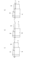
本実施形態に係る照明装置1が、照明装置1を複数密接させて縦列に配置する場合においても熱膨張による影響を受けることがないことを、図6を参照しながら具体的に説明する。図6(a)は光源部から発生する熱によってカバー部材3やフレーム部材2の熱膨張が起こる前の状態を示しており、上述のように、カバー部材3の端部とフレームエンド部材22の側壁部221との間にはカバー部材3の熱膨張による変形を許容する第1スペースS1が、フレーム部材2の端部とベースエンド部材42の側壁部421との間にはフレーム部材2及びカバー部材3の熱膨張による変形を許容する第2スペースS2が、それぞれ設けられた状態になっている。
そして、フレーム部材2がカバー部材3よりも長く、フレーム部材2の端部にカバー部材3の熱膨張による変形を許容する第1スペースS1が設けられているため、照明装置1の使用時にLED実装基板5から発生する熱によってカバー部材3が長さ方向に膨張しても、当該第1スペースS1がその膨張分を吸収する。具体的には、図6(b)に示すように、カバー部材3がLED実装基板5から発生する熱によって長さ方向に膨張していっても、カバー部材3の端部がフレームエンド部材22の側壁部221に当接して第1スペースS1が埋められるまでは熱膨張が許容される。
更にベース部材4がフレーム部材2よりも長く、ベース部材4の端部にカバー部材3及びフレーム部材2の熱膨張による変形を許容する第2スペースS2が別途設けられているため、照明装置1の使用時にLED実装基板5から発生する熱によってカバー部材3のみならずフレーム部材2までもが長さ方向に膨張しても、当該第2スペースS2がその膨張分を吸収する。具体的には、図6(c)に示すように、フレーム部材2がLED実装基板5から発生する熱によって長さ方向に膨張していっても、フレーム部材3の端部がベースエンド部材42の側壁部421に当接して第2スペースS2が埋められるまでは熱膨張が許容される。このように本実施形態の照明装置1であれば、両端部にカバー部材3の熱膨張による変形を許容する第1スペースS1及びカバー部材3及びフレーム部材2の熱膨張による変形を許容する第2スペースS2が設けられているため、複数密接させて縦列に配置する場合にも熱膨張による影響を受けることがない。
特に、カバー部材3が樹脂製であり、フレーム部材2が金属製であることにより両者の熱膨張による膨張の度合いが異なり、カバー部材3の方がフレーム部材2よりも膨張分が大きくなるが、先にカバー部材3が熱膨張して第1スペースS1を満たしてしまい、カバー部材3が更に熱膨張してフレーム部材2を押し延ばしてしまっても、フレーム部材2の膨張分を第2スペースS2が別途吸収する構造となっているため、カバー部材3にだけ特別に広い膨張吸収スペースを設ける必要がない。このとき、ベース部材4はフレーム部材2よりも熱膨張係数が小さい鉄製となっているため、LED実装基板5から発生する熱によってベース部材4が熱膨張することはほとんどなく、照明装置1の全長は使用時においてもほぼ維持される。
以上、本発明に係る照明装置について図面に基づいて説明してきたが、本発明は上記実施形態に限定されることはなく、種々の変更実施が可能である。
本実施形態においてはフレームエンド部材22がフレーム本体21の両端に取り付けられており、フレーム部材2の両端部においてカバー部材3の熱膨張による変形を許容する第1スペースS1が設けられるが、これに限られるものではなく、例えばフレーム部材2の片側端部にだけフレームエンド部材22が設けられていてもよい。また、本実施形態においてはベースエンド部材42がベース本体41の両端に取り付けられており、ベース部材4の両端部においてカバー部材3及びフレーム部材2の熱膨張による変形を許容する第2スペースS2が設けられるが、これに限られるものではなく、例えばベース部材4の片側端部にだけベースエンド部材42が設けられていてもよい。なお、フレームエンド部材22及びベースエンド部材42が片側にだけ設けられるときには、フレームエンド部材22及びベースエンド部材42が同じ端部側に設けられることが好ましい。
また、フレーム部材2の端部におけるカバー部材3の熱膨張による変形を許容する第1スペースS1、ベース部材4の端部におけるカバー部材3及びフレーム部材2の熱膨張による変形を許容する第2スペースS2はいずれもどのような設け方をしてもよく、例えばフレーム部材2の端部に設けられたフレームエンド部材22にカバー部材3が潜り込んでいくようにして熱膨張吸収スペースを確保してもよいし、ベース部材4の端部に設けられたベースエンド部材42にフレーム部材2が潜り込んでいくようにして熱膨張吸収スペースを確保してもよい。
さらに、照明装置1の構成や、フレーム部材2やカバー部材3、ベース部材4等の形状、LED実装基板5におけるLEDの配列等も自由に変更が可能である。
1 照明装置
2 フレーム部材
21 フレーム本体
211 ヒートシンク
212 基板装着スロット
213 取付溝部
22 フレームエンド部材(第1エンド部)
221 側壁部
221a 側壁台形部
221b 側壁楕円部
222 嵌合部
222a 嵌合台形部
222b 嵌合楕円部
3 カバー部材
31 取付爪部
4 ベース部材
41 ベース本体
42 ベースエンド部材(第2エンド部)
421 側壁部
421a プレート部
421b ブロック部
421c スリット
422 嵌合部
5 LED実装基板
2 フレーム部材
21 フレーム本体
211 ヒートシンク
212 基板装着スロット
213 取付溝部
22 フレームエンド部材(第1エンド部)
221 側壁部
221a 側壁台形部
221b 側壁楕円部
222 嵌合部
222a 嵌合台形部
222b 嵌合楕円部
3 カバー部材
31 取付爪部
4 ベース部材
41 ベース本体
42 ベースエンド部材(第2エンド部)
421 側壁部
421a プレート部
421b ブロック部
421c スリット
422 嵌合部
5 LED実装基板
Claims (6)
- 長尺状の光源部が設けられた、第1の金属製の長尺状のフレーム部材と、
前記光源部を覆うように前記フレーム部材に取り付けられる、樹脂製の長尺状のカバー部材と、
前記フレーム部材を挟んで前記カバー部材に相対するように前記フレーム部材に取り付けられる、前記第1の金属よりも熱膨張係数が小さい第2の金属製の長尺状のベース部材と、を備え、
前記フレーム部材が前記カバー部材よりも長く、前記フレーム部材の少なくとも何れか一方の端部に前記カバー部材の熱膨張による変形を許容する第1スペースが設けられており、
前記ベース部材が前記フレーム部材よりも長く、前記ベース部材の少なくとも何れか一方の端部に前記フレーム部材の熱膨張による変形を許容する第2スペースが設けられている照明装置。 - 前記第1の金属の熱膨張係数が20~28(×10-6/℃)であり、前記第2の金属の熱膨張係数が10~12(×10-6/℃)である、請求項1に記載の照明装置。
- 前記フレーム部材の少なくとも何れか一方の端部には第1エンド部が設けられており、
前記カバー部材の端部が前記第1エンド部の一部を覆うように、前記カバー部材が前記フレーム部材に取り付けられている、請求項1又は2に記載の照明装置。 - 前記第1エンド部が樹脂製である、請求項3に記載の照明装置。
- 前記ベース部材の少なくとも何れか一方の端部には第2エンド部が設けられており、
前記フレーム部材の端部が前記第2エンド部の一部を覆うように、前記フレーム部材が前記ベース部材に取り付けられている、請求項1~4の何れか1項に記載の照明装置。 - 前記第2エンド部が樹脂製である、請求項5に記載の照明装置。
Priority Applications (1)
| Application Number | Priority Date | Filing Date | Title |
|---|---|---|---|
| JP2018504466A JP6417494B2 (ja) | 2016-03-07 | 2017-03-06 | 照明装置 |
Applications Claiming Priority (2)
| Application Number | Priority Date | Filing Date | Title |
|---|---|---|---|
| JP2016043704 | 2016-03-07 | ||
| JP2016-043704 | 2016-03-07 |
Publications (1)
| Publication Number | Publication Date |
|---|---|
| WO2017154810A1 true WO2017154810A1 (ja) | 2017-09-14 |
Family
ID=59789363
Family Applications (1)
| Application Number | Title | Priority Date | Filing Date |
|---|---|---|---|
| PCT/JP2017/008677 Ceased WO2017154810A1 (ja) | 2016-03-07 | 2017-03-06 | 照明装置 |
Country Status (2)
| Country | Link |
|---|---|
| JP (1) | JP6417494B2 (ja) |
| WO (1) | WO2017154810A1 (ja) |
Cited By (3)
| Publication number | Priority date | Publication date | Assignee | Title |
|---|---|---|---|---|
| JP2018032643A (ja) * | 2017-11-30 | 2018-03-01 | 興和株式会社 | 照明装置 |
| JP2020024805A (ja) * | 2018-08-06 | 2020-02-13 | 三菱電機株式会社 | 光源ユニット、及び、照明装置 |
| JP2022162646A (ja) * | 2021-04-13 | 2022-10-25 | Dnライティング株式会社 | 長尺照明器具 |
Citations (7)
| Publication number | Priority date | Publication date | Assignee | Title |
|---|---|---|---|---|
| JP2013037915A (ja) * | 2011-08-08 | 2013-02-21 | Sharp Corp | 照明装置 |
| JP2013041669A (ja) * | 2011-08-11 | 2013-02-28 | Riki Shigeyoshi | Led照明管保持具及び該led照明管保持具を用いた直管蛍光灯形led照明の取り付け構造及びその取り付け方法 |
| JP2014056789A (ja) * | 2012-09-14 | 2014-03-27 | Mitsubishi Electric Corp | 照明ランプ |
| JP2014179207A (ja) * | 2013-03-14 | 2014-09-25 | Panasonic Corp | 光源ユニット及びそれを用いた照明器具 |
| JP2015146263A (ja) * | 2014-02-03 | 2015-08-13 | パナソニックIpマネジメント株式会社 | 光源ユニット及び照明器具 |
| JP2015201461A (ja) * | 2015-07-08 | 2015-11-12 | ローム株式会社 | Led照明装置 |
| JP2016100197A (ja) * | 2014-11-21 | 2016-05-30 | 株式会社東芝 | 映像表示装置 |
Family Cites Families (6)
| Publication number | Priority date | Publication date | Assignee | Title |
|---|---|---|---|---|
| US7207696B1 (en) * | 2006-01-18 | 2007-04-24 | Chu-Hsien Lin | LED lighting with adjustable light projecting direction |
| JP4798062B2 (ja) * | 2007-05-18 | 2011-10-19 | 東芝ライテック株式会社 | 照明器具 |
| JP5879523B2 (ja) * | 2012-02-29 | 2016-03-08 | パナソニックIpマネジメント株式会社 | 発光装置及び照明器具 |
| JP6096607B2 (ja) * | 2013-06-18 | 2017-03-15 | 三菱電機株式会社 | 照明装置 |
| JP2015109216A (ja) * | 2013-12-05 | 2015-06-11 | パナソニックIpマネジメント株式会社 | 光源ユニット及びそれを用いた照明器具 |
| JP5814447B1 (ja) * | 2014-10-17 | 2015-11-17 | アイリスオーヤマ株式会社 | 照明装置及び照明装置用発光ユニット |
-
2017
- 2017-03-06 JP JP2018504466A patent/JP6417494B2/ja not_active Expired - Fee Related
- 2017-03-06 WO PCT/JP2017/008677 patent/WO2017154810A1/ja not_active Ceased
Patent Citations (7)
| Publication number | Priority date | Publication date | Assignee | Title |
|---|---|---|---|---|
| JP2013037915A (ja) * | 2011-08-08 | 2013-02-21 | Sharp Corp | 照明装置 |
| JP2013041669A (ja) * | 2011-08-11 | 2013-02-28 | Riki Shigeyoshi | Led照明管保持具及び該led照明管保持具を用いた直管蛍光灯形led照明の取り付け構造及びその取り付け方法 |
| JP2014056789A (ja) * | 2012-09-14 | 2014-03-27 | Mitsubishi Electric Corp | 照明ランプ |
| JP2014179207A (ja) * | 2013-03-14 | 2014-09-25 | Panasonic Corp | 光源ユニット及びそれを用いた照明器具 |
| JP2015146263A (ja) * | 2014-02-03 | 2015-08-13 | パナソニックIpマネジメント株式会社 | 光源ユニット及び照明器具 |
| JP2016100197A (ja) * | 2014-11-21 | 2016-05-30 | 株式会社東芝 | 映像表示装置 |
| JP2015201461A (ja) * | 2015-07-08 | 2015-11-12 | ローム株式会社 | Led照明装置 |
Cited By (5)
| Publication number | Priority date | Publication date | Assignee | Title |
|---|---|---|---|---|
| JP2018032643A (ja) * | 2017-11-30 | 2018-03-01 | 興和株式会社 | 照明装置 |
| JP2020024805A (ja) * | 2018-08-06 | 2020-02-13 | 三菱電機株式会社 | 光源ユニット、及び、照明装置 |
| JP7353025B2 (ja) | 2018-08-06 | 2023-09-29 | 三菱電機株式会社 | 光源ユニット、及び、照明装置 |
| JP2022162646A (ja) * | 2021-04-13 | 2022-10-25 | Dnライティング株式会社 | 長尺照明器具 |
| JP7621865B2 (ja) | 2021-04-13 | 2025-01-27 | Dnライティング株式会社 | 長尺照明器具 |
Also Published As
| Publication number | Publication date |
|---|---|
| JPWO2017154810A1 (ja) | 2018-04-19 |
| JP6417494B2 (ja) | 2018-11-07 |
Similar Documents
| Publication | Publication Date | Title |
|---|---|---|
| JP6049248B2 (ja) | 照明装置 | |
| JP6276495B2 (ja) | 照明装置 | |
| US20130336008A1 (en) | Lighting Device | |
| JP2007165051A (ja) | Led照明灯 | |
| JP6308457B2 (ja) | 光源ユニット及び照明器具 | |
| KR101604290B1 (ko) | 엣지형 조명기구 | |
| JP6417494B2 (ja) | 照明装置 | |
| JP2010118277A (ja) | Led照明器具 | |
| JP2017059416A (ja) | Led照明装置 | |
| KR101224107B1 (ko) | 이중 확산형 라인바 타입 led 조명장치 | |
| CN105987299B (zh) | 一种照明装置 | |
| KR101150830B1 (ko) | 방열구조를 갖는 다용도 엘이디등기구용 조명프레임 및 이를 이용한 엘이디조명 | |
| JP5789565B2 (ja) | 照明装置 | |
| JP2014203720A (ja) | Led照明装置 | |
| US8789976B2 (en) | Integrated multi-layered illuminating unit and integrated multi-layered illuminating assembling unit | |
| KR200456372Y1 (ko) | 조명기구의 커버 프레임장치 | |
| JP2007217873A (ja) | 照明付き建具 | |
| US8770786B2 (en) | Illuminating device with light guiding frame | |
| JP2011023310A (ja) | Led照明灯 | |
| KR101475435B1 (ko) | 건축 몰딩 마감재용 조명 장치 | |
| KR101733465B1 (ko) | Led 조명등의 방열구조 | |
| TW201326684A (zh) | 背光模組 | |
| JP6200699B2 (ja) | 照明器具 | |
| KR20150080872A (ko) | Led 조명장치 | |
| JP7114299B2 (ja) | 屋外用照明装置 |
Legal Events
| Date | Code | Title | Description |
|---|---|---|---|
| ENP | Entry into the national phase |
Ref document number: 2018504466 Country of ref document: JP Kind code of ref document: A |
|
| NENP | Non-entry into the national phase |
Ref country code: DE |
|
| 121 | Ep: the epo has been informed by wipo that ep was designated in this application |
Ref document number: 17763150 Country of ref document: EP Kind code of ref document: A1 |
|
| 122 | Ep: pct application non-entry in european phase |
Ref document number: 17763150 Country of ref document: EP Kind code of ref document: A1 |