WO2017154785A1 - 流路形成板、これを備える翼、これを備えているガスタービン、及び流路形成板の製造方法 - Google Patents
流路形成板、これを備える翼、これを備えているガスタービン、及び流路形成板の製造方法 Download PDFInfo
- Publication number
- WO2017154785A1 WO2017154785A1 PCT/JP2017/008548 JP2017008548W WO2017154785A1 WO 2017154785 A1 WO2017154785 A1 WO 2017154785A1 JP 2017008548 W JP2017008548 W JP 2017008548W WO 2017154785 A1 WO2017154785 A1 WO 2017154785A1
- Authority
- WO
- WIPO (PCT)
- Prior art keywords
- passage
- face
- gas path
- flow path
- forming plate
- Prior art date
- Legal status (The legal status is an assumption and is not a legal conclusion. Google has not performed a legal analysis and makes no representation as to the accuracy of the status listed.)
- Ceased
Links
Images


Classifications
-
- F—MECHANICAL ENGINEERING; LIGHTING; HEATING; WEAPONS; BLASTING
- F01—MACHINES OR ENGINES IN GENERAL; ENGINE PLANTS IN GENERAL; STEAM ENGINES
- F01D—NON-POSITIVE DISPLACEMENT MACHINES OR ENGINES, e.g. STEAM TURBINES
- F01D9/00—Stators
- F01D9/02—Nozzles; Nozzle boxes; Stator blades; Guide conduits, e.g. individual nozzles
- F01D9/023—Transition ducts between combustor cans and first stage of the turbine in gas-turbine engines; their cooling or sealings
-
- F—MECHANICAL ENGINEERING; LIGHTING; HEATING; WEAPONS; BLASTING
- F01—MACHINES OR ENGINES IN GENERAL; ENGINE PLANTS IN GENERAL; STEAM ENGINES
- F01D—NON-POSITIVE DISPLACEMENT MACHINES OR ENGINES, e.g. STEAM TURBINES
- F01D5/00—Blades; Blade-carrying members; Heating, heat-insulating, cooling or antivibration means on the blades or the members
- F01D5/12—Blades
- F01D5/14—Form or construction
- F01D5/18—Hollow blades, i.e. blades with cooling or heating channels or cavities; Heating, heat-insulating or cooling means on blades
- F01D5/187—Convection cooling
-
- F—MECHANICAL ENGINEERING; LIGHTING; HEATING; WEAPONS; BLASTING
- F01—MACHINES OR ENGINES IN GENERAL; ENGINE PLANTS IN GENERAL; STEAM ENGINES
- F01D—NON-POSITIVE DISPLACEMENT MACHINES OR ENGINES, e.g. STEAM TURBINES
- F01D25/00—Component parts, details, or accessories, not provided for in, or of interest apart from, other groups
- F01D25/08—Cooling; Heating; Heat-insulation
- F01D25/12—Cooling
-
- F—MECHANICAL ENGINEERING; LIGHTING; HEATING; WEAPONS; BLASTING
- F01—MACHINES OR ENGINES IN GENERAL; ENGINE PLANTS IN GENERAL; STEAM ENGINES
- F01D—NON-POSITIVE DISPLACEMENT MACHINES OR ENGINES, e.g. STEAM TURBINES
- F01D5/00—Blades; Blade-carrying members; Heating, heat-insulating, cooling or antivibration means on the blades or the members
- F01D5/02—Blade-carrying members, e.g. rotors
- F01D5/08—Heating, heat-insulating or cooling means
- F01D5/081—Cooling fluid being directed on the side of the rotor disc or at the roots of the blades
-
- F—MECHANICAL ENGINEERING; LIGHTING; HEATING; WEAPONS; BLASTING
- F01—MACHINES OR ENGINES IN GENERAL; ENGINE PLANTS IN GENERAL; STEAM ENGINES
- F01D—NON-POSITIVE DISPLACEMENT MACHINES OR ENGINES, e.g. STEAM TURBINES
- F01D5/00—Blades; Blade-carrying members; Heating, heat-insulating, cooling or antivibration means on the blades or the members
- F01D5/12—Blades
- F01D5/14—Form or construction
- F01D5/147—Construction, i.e. structural features, e.g. of weight-saving hollow blades
-
- F—MECHANICAL ENGINEERING; LIGHTING; HEATING; WEAPONS; BLASTING
- F01—MACHINES OR ENGINES IN GENERAL; ENGINE PLANTS IN GENERAL; STEAM ENGINES
- F01D—NON-POSITIVE DISPLACEMENT MACHINES OR ENGINES, e.g. STEAM TURBINES
- F01D9/00—Stators
- F01D9/02—Nozzles; Nozzle boxes; Stator blades; Guide conduits, e.g. individual nozzles
-
- F—MECHANICAL ENGINEERING; LIGHTING; HEATING; WEAPONS; BLASTING
- F02—COMBUSTION ENGINES; HOT-GAS OR COMBUSTION-PRODUCT ENGINE PLANTS
- F02C—GAS-TURBINE PLANTS; AIR INTAKES FOR JET-PROPULSION PLANTS; CONTROLLING FUEL SUPPLY IN AIR-BREATHING JET-PROPULSION PLANTS
- F02C7/00—Features, components parts, details or accessories, not provided for in, or of interest apart form groups F02C1/00 - F02C6/00; Air intakes for jet-propulsion plants
- F02C7/12—Cooling of plants
- F02C7/16—Cooling of plants characterised by cooling medium
- F02C7/18—Cooling of plants characterised by cooling medium the medium being gaseous, e.g. air
-
- F—MECHANICAL ENGINEERING; LIGHTING; HEATING; WEAPONS; BLASTING
- F05—INDEXING SCHEMES RELATING TO ENGINES OR PUMPS IN VARIOUS SUBCLASSES OF CLASSES F01-F04
- F05D—INDEXING SCHEME FOR ASPECTS RELATING TO NON-POSITIVE-DISPLACEMENT MACHINES OR ENGINES, GAS-TURBINES OR JET-PROPULSION PLANTS
- F05D2230/00—Manufacture
- F05D2230/20—Manufacture essentially without removing material
- F05D2230/21—Manufacture essentially without removing material by casting
-
- F—MECHANICAL ENGINEERING; LIGHTING; HEATING; WEAPONS; BLASTING
- F05—INDEXING SCHEMES RELATING TO ENGINES OR PUMPS IN VARIOUS SUBCLASSES OF CLASSES F01-F04
- F05D—INDEXING SCHEME FOR ASPECTS RELATING TO NON-POSITIVE-DISPLACEMENT MACHINES OR ENGINES, GAS-TURBINES OR JET-PROPULSION PLANTS
- F05D2240/00—Components
- F05D2240/10—Stators
- F05D2240/11—Shroud seal segments
-
- F—MECHANICAL ENGINEERING; LIGHTING; HEATING; WEAPONS; BLASTING
- F05—INDEXING SCHEMES RELATING TO ENGINES OR PUMPS IN VARIOUS SUBCLASSES OF CLASSES F01-F04
- F05D—INDEXING SCHEME FOR ASPECTS RELATING TO NON-POSITIVE-DISPLACEMENT MACHINES OR ENGINES, GAS-TURBINES OR JET-PROPULSION PLANTS
- F05D2240/00—Components
- F05D2240/20—Rotors
- F05D2240/30—Characteristics of rotor blades, i.e. of any element transforming dynamic fluid energy to or from rotational energy and being attached to a rotor
- F05D2240/304—Characteristics of rotor blades, i.e. of any element transforming dynamic fluid energy to or from rotational energy and being attached to a rotor related to the trailing edge of a rotor blade
-
- F—MECHANICAL ENGINEERING; LIGHTING; HEATING; WEAPONS; BLASTING
- F05—INDEXING SCHEMES RELATING TO ENGINES OR PUMPS IN VARIOUS SUBCLASSES OF CLASSES F01-F04
- F05D—INDEXING SCHEME FOR ASPECTS RELATING TO NON-POSITIVE-DISPLACEMENT MACHINES OR ENGINES, GAS-TURBINES OR JET-PROPULSION PLANTS
- F05D2240/00—Components
- F05D2240/80—Platforms for stationary or moving blades
- F05D2240/81—Cooled platforms
Definitions
- the present invention relates to a flow path forming plate that defines a combustion gas flow path through which combustion gas flows, a blade including the same, a gas turbine including the same, and a method of manufacturing the flow path forming plate.
- the gas turbine includes a rotor that rotates about an axis and a casing that covers the rotor.
- the rotor has a rotor shaft and a plurality of moving blades attached to the rotor shaft.
- a plurality of stationary blades are provided inside the cabin.
- the blade has a radially extending wing body with respect to the axis, a platform provided radially inward of the wing body, and a wing root provided radially inward of the platform.
- the blade of the moving blade is disposed in the combustion gas flow path through which the combustion gas passes.
- the platform defines a radially inner edge of the combustion gas flow path.
- the blade root is fixed to the rotor shaft.
- the vane has a radially extending wing body with respect to the axis, an inner shroud provided radially inward of the wing body, and an outer shroud provided radially outward of the wing body.
- the vanes of the stator vanes are disposed in the combustion gas flow path through which the combustion gas passes.
- the inner shroud defines a radially inner edge of the combustion gas flow path.
- the outer shroud defines a radially outer edge of the combustion gas flow path.
- the casing has a split ring facing the moving blades in the radial direction with respect to the axis.
- the split annulus defines the radially outer edge of the combustion gas flow path.
- the rotor blade platform, the outer shroud and the inner shroud of the stator blade, and the split ring all form a flow path forming plate that defines the combustion gas flow path.
- the flow path forming plate is exposed to the high temperature combustion gas. For this reason, the flow path forming plate is generally cooled by air or the like.
- Patent Document 1 discloses an inner shroud of a vane, which is a type of flow path forming plate.
- the inner shroud is formed with a rear side passage along the rear end surface and a plurality of rear end surface jet passages.
- the plurality of rear end face ejection passages are in communication with the rear end face passage and open at the rear end face. That is, in this inner shroud, cooling air flows into the rear passage.
- the cooling air flows from the rear passage into the plurality of rear end face ejection passages.
- the cooling air flowing into the rear end face ejection passage flows out from the opening of the rear end face ejection passage at the rear end face.
- Patent No. 3978143 gazette
- the flow path forming plate is desired to efficiently cool the gas path surface in contact with the combustion gas.
- the present invention has an object of providing a flow path forming plate capable of efficiently cooling a gas path surface, a blade provided with the same, a gas turbine provided with the same, and a method of manufacturing the flow path forming plate. Do.
- the flow path forming plate as one aspect according to the invention for achieving the above object is: A flow path forming plate for demarcating a combustion gas flow path through which combustion gas flows, which is formed on a gas path surface in contact with the combustion gas, an opposite gas path surface facing the opposite side to the gas path surface, and a periphery of the gas path surface A first side passage extending in a direction along a first end face which is a part of the end face between the end face and the gas path face and the opposite gas path face, and the first side And a plurality of end face ejection passages communicating and opening at the first end face.
- the passage cross-sectional area of the end face ejection passage is smaller than the passage cross-sectional area of the first side passage.
- the first side passage is defined by a plurality of passage forming surfaces.
- the first formation surface faces the opposite flow passage side opposite to the flow passage side which is the gas path surface side on the basis of the opposite gas path surface, and approaches the first end surface
- the gas path surface is gradually moved away from the gas path surface toward the end face side.
- the plurality of end surface ejection passages open at the first formation surface.
- the end face side portion of the flow path forming plate is cooled in the process of the cooling air flowing through the first side passage.
- the cooling air flows from the first side passage into the plurality of end face ejection passages.
- the cooling air convectively cools the end face side portion of the flow path forming plate in the process of flowing through the end face ejection passage.
- the passage cross-sectional area of the end face ejection passage is smaller than the passage cross-sectional area of the first side passage. In other words, the passage cross-sectional area of the first side passage is larger than the passage cross-sectional area of the end face ejection passage. Therefore, the flow velocity of the cooling air flowing through the first side passage can be suppressed.
- the pressure loss in the process of the cooling air flowing through the first side passage can be suppressed.
- the effect of cooling by the cooling air flowing through the end face ejection passage is higher than the effect of cooling by the cooling air flowing through the first side passage per unit passage cross sectional area.
- the end face ejection passage faces the opposite flow path side among the passage forming faces forming the first side passage, and opens at the first forming face which is gradually separated from the gas path face as it goes to the end face side. For this reason, the end on the opposite end face side of the end face ejection passage opens at a position opposite to the end face side than the portion closest to the end face side on the passage forming surface forming the first side passage.
- the passage length of the end face ejection passage having a high cooling effect becomes long.
- the end face side portion of the gas path surface can be effectively cooled without increasing the flow rate of the cooling air.
- the above-mentioned "direction from the gas path surface to the opposite gas path surface" is a radial direction which is a direction intersecting the axis.
- At least one side of the plurality of sides forming the passage cross section of the first side passage may be a straight line.
- the inner angles of the respective corners formed by the adjacent sides are all 180 ° or less It may be.
- the flow path forming plate it is possible to suppress the decrease in the cross-sectional area of the first side passage, and to suppress the pressure loss in the process of the cooling air flowing through the first side passage.
- the second forming face faces the opposite flow path side, and the opposite end face on the first forming face opposite to the end face side
- the second formation surface may extend substantially parallel to the gas path surface, extending from the side edge to the opposite end surface side.
- a third formation surface of the plurality of passage formation surfaces may face the flow path side and may extend along the opposite gas path surface.
- the fact that the third formation surface extends along the antigas path surface means that the third formation surface is substantially parallel to the antigas path surface. Therefore, regarding the distance between the third formation surface and the opposite gas path surface, the allowable distance is determined from the strength as the flow path formation plate, the ease of manufacture in the process of manufacturing the flow path formation plate, and the like. .
- the flow path forming plate by making the third formation surface along the opposite gas path surface, the passage cross sectional area of the first side passage is obtained while the distance between the third formation surface and the opposite gas path surface is separated by the allowable distance or more. Can be increased.
- the flow path forming plate according to any one of the above may be provided with a plurality of first gas path surface jet passages communicating with the first side passage and opening at the gas path surface.
- the gas path surface can be further cooled by the cooling air flowing through the first gas path surface ejection passage.
- the flow path forming plate having the second formation surface includes: a plurality of first gas path surface ejection passages communicating with the first side passage and opening at the gas path surface; and the plurality of first gas path surface ejection passages
- the second formation surface may be open.
- the gas path surface can be further cooled by the cooling air flowing through the first gas path surface ejection passage. Further, in the flow path forming plate, the first gas path surface jet passage can be easily formed without interfering with the end face jet passage.
- the plurality of first gas path surface ejection paths may gradually approach the flow path side toward the end face side.
- the gas path surface can be film-cooled by the cooling air from the first gas path surface ejection passage.
- the flow path forming plate according to any one of the above, further comprising a peripheral wall provided along the end face and protruding from the opposite gas path surface to the opposite flow path side, wherein the opposite gas path surface and the peripheral wall are on the flow path side
- the recess may be formed with a recess into which the cooling air flows.
- the flow path forming plate in which the concave portion is formed may include a plurality of second gas path surface jet passages communicating with a space in the concave portion and opening at the gas path surface.
- the gas path surface can be further cooled by the cooling air flowing through the second gas path surface ejection passage.
- the plurality of second gas path surface ejection passages may gradually approach the flow channel side toward the end face side.
- the gas path surface can be film-cooled by the cooling air from the second gas path surface ejection passage.
- a communication passage may be provided which communicates with a space in the recess and the first side passage.
- the peripheral wall has a first wall provided along the first end face, and the communication passage defines the space by the surface of the first wall. It may be open at the bottom surface of the concave surface or the concave surface.
- the end face is a second end face extending in a direction intersecting with the first end face from the first end of the first end face in the direction in which the first side passage extends; And a third end surface extending in a direction intersecting with the first end surface from a second end opposite to the first end of the first end surface in a direction in which the first side passage extends.
- a second side passage extending in a direction along the second end face between the gas path surface and the opposite gas path surface, through which cooling air flows, and the third side between the gas path surface and the opposite gas path surface
- a third side passage extending in a direction along the end face and through which the cooling air flows.
- the first side passage may be in communication with the second side passage and the third side passage.
- a wing according to an aspect of the invention for achieving the above object is: The flow path forming plate according to any one of the above, and a wing body having an airfoil shape and extending from the gas path surface of the flow path forming plate to the flow path side.
- the first end face may be an aft end face facing in the axial direction downstream side where the combustion gas flows.
- a wing comprising: The flow path forming plate according to any one of the above, provided with the first gas path surface jet passage, and a wing body forming an airfoil and extending from the gas path surface of the flow path forming plate to the flow path side
- the first end surface is a rear end surface facing the axial direction downstream side through which the combustion gas flows, and openings on the gas path surface in the plurality of first gas path surface jet passages are on the axial direction downstream side than the wing body is there.
- the end face of the flow path forming plate is a ventral side extending in a direction intersecting the rear end face from the first end of the rear end face in the first direction in which the first side passage extends.
- An end surface, and a back end surface extending in a direction intersecting the rear end surface from a second end opposite to the first end of the rear end surface in the first direction.
- a middle region not including the edge with the back end surface and the edge with the ventral end surface in the rear end surface, and the edge with the back end surface in the rear end surface, the middle region and the first direction Openings of a plurality of the end surface ejection passages are provided in each of the middle region and the ventral side region adjacent in the first direction including the edge of the adjacent back side region and the ventral side end surface in the rear end surface. They are formed side by side in the first direction.
- the opening density of the plurality of end face ejection passages in the middle region may be higher.
- the middle region In the gas path plane, in the portion axially downstream of the wing body, the middle region is more easily heated by the combustion gas than the ventral region and the back region, and is cooled by the cooling air flowing through the first side passage hard.
- the openings of the plurality of end surface ejection passages in the middle region in the rear end surface are more than the opening densities of the plurality of end surface ejection passages in at least one side region of the back region and the ventral region in the rear end surface Density is higher. For this reason, in the said wing
- the opening density of the plurality of end surface ejection passages in the middle region is higher, and at least three or more of the end surface ejections aligned in the first direction in the dorsal region and the ventral region.
- An opening of the passage may be formed.
- a gas turbine according to one aspect of the invention for achieving the above object is: The flow path forming plate according to any one of the above, and a combustor that generates the combustion gas.
- a gas turbine according to another aspect of the invention for achieving the above object is: And a combustor configured to generate the combustion gas.
- a method of manufacturing a flow path forming plate In a method of manufacturing a flow path forming plate that defines a combustion gas flow path through which combustion gas flows, a gas path surface in contact with the combustion gas, an opposite gas path surface facing the gas path surface, and a periphery of the gas path surface Between the gas path surface and the counter gas path surface, extending in a direction along a first end surface which is a part of the end surface, and through which cooling air flows Performing a side passage forming step of forming a jet passage and a jet passage forming step of forming a plurality of end surface jet passages communicating with the first side passage and opening at the first end surface.
- a plurality of passage forming surfaces which define the first side passage are formed.
- the first formation surface faces the side opposite to the gas path surface with reference to the gas path surface, and gradually moves away from the gas path surface as it approaches the first end surface.
- a plurality of the end face jet passages are formed such that a passage sectional area of the plurality of end face jet passages is smaller than a passage sectional area of the first side passage, and a plurality of the end face jet passages are formed.
- the first formation surface is opened.
- the portion on the first end face side in the gas path surface of the flow path forming plate can be effectively cooled.
- FIG. 5 is a cross-sectional view taken along the line V-V in FIG. 4;
- FIG. 6 is a cross-sectional view taken along line VI-VI in FIG. 4;
- FIG. 7 is a cross-sectional view taken along line VII-VII in FIG. 5; Fig.
- FIG. 6 shows a first variant of the rear passage of the inner shroud according to the invention; The figure is a cross-sectional view of this rear side passage. The 2nd modification of the back side passage of the inner side shroud concerning the present invention is shown. The figure is a cross-sectional view of this rear side passage. Fig. 6 shows a third variant of the rear passage of the inner shroud according to the invention; The figure is a cross-sectional view of this rear side passage. The 4th modification of the back side passage of the inner side shroud concerning the present invention is shown. The figure is a cross-sectional view of this rear side passage. The 5th modification of the back side channel of the inner side shroud which concerns on this invention is shown.
- FIG. 7 is a cross-sectional view taken along line XV-XV in FIG. Fig.
- FIG. 5 shows a first variant of the rear passage of the outer shroud according to the invention;
- the figure is a cross-sectional view of this rear side passage.
- the 2nd modification of the back side passage of the outer side shroud concerning the present invention is shown.
- the figure is a cross-sectional view of this rear side passage.
- 1 shows a first variant of the inner shroud according to the invention.
- the figure is a plan view of the inner shroud from the radial outside.
- FIG. 19 is a cross-sectional view taken along line XIX-XIX in FIG.
- Fig. 6 shows a second variant of the inner shroud according to the invention;
- the figure is a cross-sectional view corresponding to a cross-sectional view taken along the line V-V in FIG. Fig.
- FIG. 6 shows a third variant of the inner shroud according to the invention.
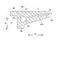
- the figure is a cross-sectional view corresponding to the cross-sectional view taken along the line VV in FIG. It is a perspective view of the bucket in one embodiment concerning the present invention. It is sectional drawing in the cross section which followed the wing-blade centerline of the moving blade in one Embodiment which concerns on this invention.
- FIG. 24 is a cross-sectional view taken along the line XXIV-XXIV in FIG. It is a perspective view of the ring segment in one embodiment concerning the present invention. It is an XXVI arrow line view in FIG.
- FIG. 27 is a cross-sectional view taken along line XXVII-XXVII in FIG.
- the gas turbine 1 of the present embodiment includes a compressor 10 that compresses external air A to generate compressed air Acom, and burns fuel F from a fuel supply source in the compressed air Acom for combustion.
- a combustor 20 generating gas G and a turbine 30 driven by the combustion gas G are provided.
- the compressor 10 has a compressor rotor 11 that rotates around an axis Ar and a cylindrical compressor casing 15 that covers the compressor rotor 11.
- the direction in which the axis Ar extends is referred to as an axial direction Da.
- one side of the axial direction Da is referred to as an axially upstream side Dau, and the other side of the axial direction Da is referred to as an axially downstream side Dad.
- the radial direction with respect to the axis Ar is simply referred to as the radial direction Dr.
- the side away from the axis Ar in the radial direction Dr is referred to as the radially outer side Dro
- the side approaching the axis Ar in the radial direction Dr is referred to as the radially inner side Dri.
- An opening is formed on the upstream side of the compressor casing 15. This opening forms an air intake port 15i through which the compressor 10 takes in the outside air A from the outside.
- a plurality of vane arrays 16 are fixed to the radially inner side Dri of the compressor casing 15. The plurality of vane arrays 16 are spaced apart in the axial direction Da. Each of the plurality of vane arrays 16 is constituted by a plurality of vanes 17 arranged in the circumferential direction Dc with respect to the axis Ar.
- the compressor rotor 11 has a rotor shaft 12 extending in the axial direction Da around an axis Ar and a plurality of moving blade arrays 13 fixed to the outer periphery of the rotor shaft 12. Each moving blade row 13 is disposed on the axially upstream side Dau of any one of the blade rows 16.
- Each of the plurality of moving blade arrays 13 includes a plurality of moving blades 14 arranged in the circumferential direction Dc.
- the turbine 30 is disposed on the axially downstream side Dad of the compressor 10.
- the turbine 30 has a turbine rotor 31 that rotates about an axis Ar and a cylindrical turbine casing 41 that covers the turbine rotor 31.
- a plurality of vane arrays 46 are fixed to the radially inner side Dri of the turbine casing 41.
- the plurality of stator blade arrays 46 are spaced apart in the axial direction Da.
- Each of the plurality of vane arrays 46 includes a plurality of vanes 47 arranged in the circumferential direction Dc.
- the turbine rotor 31 has a rotor shaft 32 extending in the axial direction Da around an axis Ar, and a plurality of moving blade arrays 33 fixed to the outer periphery of the rotor shaft 32.
- Each moving blade row 33 is disposed on the axially downstream side Dad of one of the stationary blade rows 46.
- Each of the plurality of moving blade rows 33 is configured of a plurality of moving blades 34 aligned
- the gas turbine 1 of the present embodiment further includes an intermediate casing 5 and an exhaust chamber 6.
- the intermediate casing 5 is disposed between the compressor casing 15 and the turbine casing 41 in the axial direction Da.
- the exhaust chamber 6 is disposed on the axially downstream side Dad of the turbine casing 41.
- the compressor casing 15, the intermediate casing 5, the turbine casing 41, and the exhaust chamber 6 are connected to one another to form a gas turbine casing 3.
- the compressor rotor 11 and the turbine rotor 31 integrally rotate around the same axis Ar.
- the compressor rotor 11 and the turbine rotor 31 constitute a gas turbine rotor 2.
- the gas turbine rotor 2 is supported by bearings at both ends in the axial direction Da.
- the rotor of the generator 9 is connected to the gas turbine rotor 2.
- the combustor 20 is fixed to the intermediate vehicle chamber 5.
- a fuel line 25 for supplying fuel F to the combustor 20 is connected to the combustor 20.
- the fuel line 25 is provided with a fuel control valve 26 for adjusting the fuel flow rate.
- the turbine casing 41 has a plurality of split rings 42, a plurality of heat shield rings 43, a blade ring 44 as a first part, and a casing main body 45.
- the split ring 42 is located on the radially outer side Dro of the moving blade row 33, and faces the moving blade row 33 in the radial direction Dr.
- the blade ring 44 has an annular shape about the axis Ar, and is located radially outward Dro of the plurality of split rings 42.
- the heat shield ring 43 is located between the split ring 42 and the vane 47 and the heat shield ring 43 in the radial direction Dr, and connects the split ring 42 and the vane 47 with the heat shield ring 43.
- the casing body 45 has an annular shape about the axis Ar, and is located on the radially outer side Dro of the blade ring 44.
- the casing body 45 supports the wing ring 44 from the radially outer side Dro.
- An intermediate vehicle compartment 5 is connected to the axially upstream side Dau of the casing main body 45. Further, an exhaust chamber 6 is connected to the axially downstream side Dad of the casing main body 45.
- An annular space between the radially outer side Dro of the rotor shaft 32 and the radially inner side Dri of the turbine casing 41 forms a combustion gas flow path 49 through which the combustion gas G from the combustor 20 flows.
- the rotor shaft 32 is formed with a cooling air passage through which the cooling air passes.
- the cooling air having passed through the cooling air passage is introduced into the moving blade 34 and is used to cool the moving blade 34.
- the turbine casing 41 is formed with a cooling air passage through which the cooling air passes.
- the cooling air that has passed through the cooling air passage is introduced into the vane 47 and into the split ring 42 and used to cool the vane 47 and the split ring 42.
- the air in the intermediate vehicle chamber 5 may be supplied as cooling air to the stationary blades 47 constituting the stationary blade row 46 without passing through the cooling air passage of the vehicle compartment. .
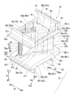
- the vane 50 includes a wing 51 extending in the radial direction Dr, an inner shroud 60 i formed on the radially inner side Dri of the wing 51, and a radial direction of the wing 51. And an outer shroud 60o formed on the outer side Dro.
- the wing body 51 is disposed in a combustion gas passage 49 (see FIG. 2) through which the combustion gas G passes.
- the inner shroud 60i defines the edge of the radially inner Dri of the annular combustion gas passage 49.
- the outer shroud 60 o defines the edge of the radially outer side Dro of the annular combustion gas flow path 49.
- the inner shroud 60i and the outer shroud 60o are both flow path forming plates that define a portion of the combustion gas flow path 49.
- the wing body 51 has an airfoil shape as shown in FIGS.
- an end portion of the axially upstream side Dau forms a front edge portion 52
- an end portion of the axially downstream side Dad forms a rear edge portion 53.
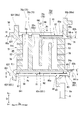
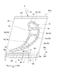
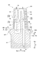
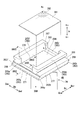
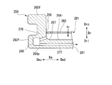
- the inner shroud 60i which is a flow path forming plate has an inner shroud main body 61i and a peripheral wall 65i.
- the inner shroud main body 61i has a front end face 62f which is an end face of the axially upstream side Dau, a rear end face 62b which is an end face of the axially downstream side Dad, and a pair of circumferential directions facing mutually opposite sides in the circumferential direction Dc.
- An end face 63, a gas path surface 64p facing the radially outer side Dro, and an opposite gas path surface 64i facing the radially inner side Dri are formed.
- the end face of the circumferential abdominal side Dcp constitutes an abdominal end face 63p
- the end face of the circumferential back side Dcn constitutes a back end face 63n.
- the front end face 62f and the rear end face 62b are substantially parallel.
- the ventral end face 63p and the back end face 63n are substantially parallel. Therefore, the inner shroud main body 61i has a parallelogram as shown in FIG. 5 when viewed in the radial direction Dc.
- the circumferential wall 65i protrudes from the opposite gas path surface 64i of the inner shroud main body 61i radially inward Dri (the opposite flow path side).
- the peripheral wall 65i is provided along the end face of the inner shroud main body 61i.
- the peripheral wall 65i has a front wall 65f and a rear wall 65b facing each other in the axial direction Da, and a pair of side walls 65p and 65n facing each other in the circumferential direction Dc.
- the side wall of the circumferential ventral side Dcp constitutes an abdominal side wall 65p
- the sidewall of the circumferential back side Dcn constitutes a back side wall 65n.
- the front wall 65f and the rear wall 65b both project with respect to the inner shroud main body 61i at a radially inner side Dri than the pair of side walls 65p, 65n.
- a recess 66 (see FIGS. 4 and 5) recessed toward the radially outer side Dro is formed by the inner shroud main body 61i and the peripheral wall 65i.
- the surface on the circumferential side Dcp of the abdominal wall 65p is flush with the surface on the circumferential side Dcp of the inner shroud main body 61i.
- the surface of the circumferential back side Dcn of the back side wall 65n and the surface of the circumferential back side Dcn of the inner shroud main body 61i are flush with each other.
- the rear wall 65b is formed along the rear end surface 62b of the inner shroud main body 61i, the rear wall 65b is formed on the axially upstream side Dau side with respect to the rear end surface 62b.
- the surface of the axially upstream side Dau of the opposite gas path surface 64i of the inner shroud main body 61i with respect to the rear wall 65b forms the bottom surface of the recess 66 described above.
- the surface on the axially downstream side Dad with respect to the rear wall 65b does not form the bottom surface of the recess 66 described above, and forms an outer opposite gas path surface 64io.
- the outer opposite gas path surface 64io of the inner shroud 60i is formed so as to gradually approach the gas path surface 64p toward the axially downstream side Dad.
- the opposite flow path side means a direction away from the combustion gas flow path 49 or the gas path surface 64p in the radial direction Dr
- the flow path side means a direction approaching the combustion gas flow path 49 or the gas path surface 64p in the radial direction Dr say.
- the flow path side coincides with the radially outer side Dro, and the opposite flow side coincides with the radially inner side Dri.
- the flow path side coincides with the radially inner side Dri, and the opposite flow side coincides with the radially outer side Dro.
- the vanes 50 constituting one of the vane arrays 46 are provided with retainers 85 projecting radially inward Dri from the pair of side walls 65p, 65n of the inner shroud 60i. .
- the retainer 85 is located between the front wall 65f and the rear wall 65b in the axial direction Da, and is formed from the ventral end face 63p to the back end face 63n.
- the ventral end surface of the retainer 85 is flush with the ventral end surface 63p of the inner shroud main body 61i.
- the back end surface of the retainer 85 is flush with the back end surface 63n of the inner shroud main body 61i.
- the retainer 85 is in contact with the downstream radially outer end 8 a (see FIG. 4) of the inner cover 8 fixed to the gas turbine casing 3, and the radially inner Dri portion of the vane 50 is the inner cover 8. It serves to support the radially outer end 8a.
- the retainer 85 is formed with an opening 86 (hereinafter referred to as a retainer opening 86) penetrating in the axial direction Da.
- the space formed by the retainer opening 86 communicates with the space formed by the recess 66 of the inner shroud 60i.
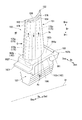
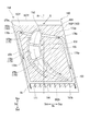
- the vane 50 further includes an impingement plate 81, as shown in FIG.
- the stationary blade 50 provided with the retainer 85 includes an impingement plate 81 and a sealing plate 83.
- the impingement plate 81 divides the space in the recess 66 of the inner shroud 60i into an outer cavity 66a which is an area of the radially inner Dri and an inner cavity 67 which is an area of the radially outer Dro.
- the impingement plate 81 is formed with a plurality of through holes 82 penetrating in the radial direction Dr. A portion of the cooling air Ac present in the radially inner side Dri of the vane 50 flows into the inner cavity 67 through the through hole 82 of the impingement plate 81.
- the sealing plate 83 closes a portion of the opening of the recess 66 axially downstream side Dad than the retainer 85.
- the sealing plate 83 is located on the downstream side Dad of the retainer 85 and is located radially inward Dri of the impingement plate 81.
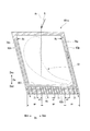
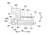
- the outer shroud 60o which is a flow path forming plate, has an outer shroud main body 61o and a peripheral wall 65o, as shown in FIGS. Similarly to the inner shroud main body 61i, the outer shroud main body 61o is formed with a front end face 62f, a rear end face 62b, a pair of circumferential end faces 63, a gas path surface 64p, and an anti-gas path surface 64i. Of the pair of circumferential end faces 63, the end face of the circumferential abdominal side Dcp constitutes an abdominal end face 63p, and the end face of the circumferential back side Dcn constitutes a back end face 63n.
- the outer shroud main body 61o Similar to the inner shroud main body 61i, the outer shroud main body 61o also has a parallelogram when viewed from the radial direction Dc.
- the gas path surface 64p of the inner shroud main body 61i faces the radially outer side Dro, but the gas path surface 64p of the outer shroud main body 61o faces the radial inner side Dri.
- the peripheral wall 65o has a front wall 65f and a rear wall 65b facing each other in the axial direction Da, and a pair of side walls 65p and 65n facing each other in the circumferential direction Dc.
- the side wall of the circumferential ventral side Dcp constitutes an abdominal side wall 65p
- the sidewall of the circumferential back side Dcn constitutes a back side wall 65n.
- the front wall 65f and the rear wall 65b both project to the radially outer side Dro more than the pair of side walls 65p, 65n with respect to the outer shroud main body 61o, and form a hook portion.
- the front wall 65 f and the rear wall 65 b forming the hooks serve to attach the vane 50 to the inner circumferential side of the turbine casing 41.
- the front wall 65 f and the rear wall 65 b forming the hook portion are attached to the heat shield ring 43 (see FIG. 2) that constitutes a part of the turbine casing 41.
- the outer shroud 60o is formed with a recess 66 which is recessed toward the radially inner side Dri by the outer shroud main body 61o and the peripheral wall 65o.
- the surface on the circumferential side Dcp of the abdominal side wall 65p is flush with the surface of the circumferential side Dcp on the outer shroud main body 61o.
- the surface of the circumferential back side Dcn of the back side wall 65n and the surface of the circumferential back side Dcn of the outer shroud main body 61o are flush with each other.
- the rear wall 65b is formed along the rear end face 62b of the outer shroud main body 61o, the rear wall 65b is formed on the axially upstream side Dau side with respect to the rear end face 62b.
- the surface of the axially upstream side Dau of the opposite gas path surface 64i of the outer shroud main body 61o with respect to the rear wall 65b forms the bottom surface of the recess 66 described above.
- the surface on the axially downstream side Dad with respect to the rear wall 65b does not form the bottom surface of the recess 66 described above, and forms an outer opposite gas path surface 64io.
- the outer opposite gas path surface 64io of the outer shroud 60o is formed so as to gradually approach the gas path surface 64p toward the axially downstream side Dad.
- the vane 50 further includes an impingement plate 81 that divides the space in the recess 66 of the outer shroud 60 o into a region of the radially outer Dro and an inner cavity 67 that is the region of the radially inner Dri. ing.
- the impingement plate 81 is formed with a plurality of through holes 82 penetrating in the radial direction Dr. A portion of the cooling air Ac present on the radially outer side Dro of the vane 50 flows into the inner cavity 67 via the through hole 82 of the impingement plate 81.
- the wing body 51, the outer shroud 60o and the inner shroud 60i are formed with a plurality of wing air passages 75 extending in the radial direction Dr.
- Each wing air passage 75 is formed continuously from the outer shroud 60 o to the inner shroud 60 i through the wing body 51.
- the plurality of wing air passages 75 are aligned along the wing centerline of the wing 51. Portions of the two adjacent wing air passages 75 communicate with each other at the radially outer portion Dro or at the radially inner portion Dri. Further, any one of the plurality of wing air passages 75 is open at the radially outer side Dro.
- the blade air passage 75 of the most axially upstream side Dau is a first blade air passage 75a.
- the second wing air passage 75b, the third wing air passage 75c, and the fourth wing air passage 75d are arranged in this order in the axial downstream side Dad with reference to the first wing air passage 75a.
- the second wing air passage 75b communicates with the radially inner Dri portion of the third wing air passage 75c at the radially inner Dri portion.
- the third wing air passage 75c communicates with the radially outer side Dro of the fourth wing air passage 75d at the radially outer side Dro.
- the first wing air passage 75a and the second wing air passage 75b are in communication with the space in the recess 66 of the outer shroud 60o. Cooling air Ac flows into the first wing air passage 75a and the second wing air passage 75b from this opening.
- the ends of the radially outer side Dro of the third wing air passage 75c and the fourth wing air passage 75d are closed.
- the ends of the radially outer side Dro of the first wing air passage 75a, the second wing air passage 75b, the third wing air passage 75c, and the fourth wing air passage 75d are closed.
- the front edge 52 and the rear edge 53 of the wing body 51 are formed with a plurality of wing surface jet passages 76 penetrating from the wing air passage 75 to the combustion gas passage 49.
- the wing body 51 is cooled in the process of the cooling air Ac flowing in the wing air passage 75. Further, the cooling air Ac flowing into the wing air passage 75 flows out from the wing surface ejection passage 76 into the combustion gas passage 49. Therefore, the front edge 52 and the rear edge 53 of the wing body 51 are cooled in the process of the cooling air Ac flowing out of the wing surface ejection passage 76. Furthermore, part of the cooling air Ac that has flowed out of the wing surface ejection passage 76 into the combustion gas flow path 49 partially covers the surface of the wing 51 and also serves as film cooling air.
- a ventral-side passage 78p extending in a direction having an axial direction Da component along the ventral-side end face 63p is formed on the ventral-side wall 65p of the inner shroud 60i.
- a back side passage 78n extending in a direction having an axial direction Da component along the back side end face 63n is also formed on the back side wall 65n.
- Both the ventral passage 78p and the dorsal passage 78n communicate with the inner cavity 67 at the end of the axially upstream side Dau.
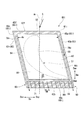
- the inner shroud main body 61i is formed with a rear side passage 90i extending in the circumferential direction Dc along the rear end face 62b.
- the end of the circumferential ventral side Dcp in the rear side passage (first side passage) 90i is in communication with the end of the axially downstream side Dad of the ventral side passage (second side passage) 78p.
- the end of the circumferential back side Dcn in the rear side passage (first side passage) 90i is in communication with the end of the axially downstream side Dad of the back side passage (third side passage) 78n.
- the position of the rear passage 90i in the axial direction Da is axially downstream Dad from the rear edge portion 53 of the wing 51, and overlaps the region where the rear wall 65b is formed (see FIG. 4).
- a plurality of rear end face ejection passages 71 communicate with the rear side passage 90i.
- the plurality of rear end face ejection passages 71 extend from the rear side passage 90i to the axially downstream side Dad and open at the rear end face 62b of the inner shroud main body 61i. Thus, the air having passed through the plurality of rear end face ejection passages 71 flows out into the combustion gas flow path 49 through this opening.
- the plurality of rear end face ejection passages 71 are arranged in the circumferential direction Dc.
- the ventral side wall 78 of the outer shroud 60o is also formed with a ventral passage 78p extending in a direction having an axial component Da along the ventral end face 63p, similarly to the ventral side wall 65p of the inner shroud 60i. ing. Further, on the back side wall 65n of the outer shroud 60o, similarly to the back side wall 65n of the inner shroud 60i, a back side passage 78n extending in a direction having an axial direction Da component is formed along the back side end face 63n. Both the ventral passage 78p and the dorsal passage 78n communicate with the inner cavity 67 at the end of the axially upstream side Dau.
- the outer shroud main body 61o is formed with a rear side passage 90o extending in the circumferential direction Dc along the rear end face 62b.
- the end of the circumferential ventral side Dcp in the rear side passage (first side passage) 90o is in communication with the end of the axially downstream side Dad of the ventral side passage (second side passage) 78p.
- the end of the circumferential back side Dcn in the rear side passage (first side passage) 90o communicates with the end of the axially downstream side Dad of the back side passage (third side passage) 78n.
- the position of the rear passage 90o in the axial direction Da overlaps the area where the rear wall 65b is formed (see FIG. 4).
- a plurality of rear end face ejection passages 71 communicate with the rear side passage 90o.
- Each of the plurality of rear end face ejection passages 71 extends from the rear side passage 90 o to the axially downstream side Dad and opens at the rear end face 62 b of the outer shroud main body 61 o.
- the plurality of rear end face ejection passages 71 are arranged in the circumferential direction Dc.
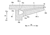
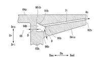
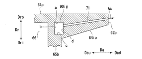
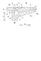
- the cross-sectional shape of the rear side passage 90i in the inner shroud 60i has an unequal square shape. Therefore, the rear side passage 90i is defined by a plurality of passage forming surfaces including the first forming surface 91, the second forming surface 92, the third forming surface 93, and the fourth forming surface 94. Among the plurality of sides forming the passage cross section of the rear side passage 90i, the side included in the first formation surface 91, the side included in the second formation surface 92, the side included in the third formation surface 93, the fourth formation All sides included in the surface 94 are substantially straight.
- the first formation surface 91, the second formation surface 92, the third formation surface 93, and the fourth formation surface 94 are all curved surfaces that extend in the circumferential direction Dc and gradually bend in the circumferential direction Dc.
- the first formation surface 91 faces the radially inner side Dri (the opposite flow path side), and gradually extends in a direction away from the gas path surface 64p toward the axially downstream side Dad (end face side).
- the first formation surface 91 is directed to the opposite flow path side and gradually extends away from the gas path surface 64p toward the end face side which is the side approaching the rear end face 62b which is the first end face.
- the second formation surface 92 faces the radially inner side Dri (the opposite flow path side), and extends from the end of the first formation surface 91 axially upstream Dau (the opposite end surface side) to the axially upstream Dau (the opposite end surface side) ing.
- the second formation surface 92 is directed to the radially inner side Dri (the opposite flow path side), and is a side away from the rear end surface 62b which is the first end surface from the end of the first formation surface 91 closest to the gas path surface 64p. It extends to the opposite end side.
- the second formation surface 92 is substantially parallel to the gas path surface 64p.
- the fourth formation surface 94 extends from the end of the axially upstream side Dau of the second formation surface 92 radially inward Dri.
- the fourth formation surface 94 is substantially parallel to the inner surface of the rear wall 65 b facing the recess 66.
- the third formation surface 93 faces the radially outer side Dro, and extends in a direction gradually approaching the gas path surface 64p toward the axially downstream side Dad.
- the end of the axially upstream side Dau of the third forming surface 93 is connected to the end of the radially inner side Dri of the fourth forming surface 94.
- an end of the third formation surface 93 on the axial downstream side Dad is connected to an end of the first formation surface 91 on the axial downstream side Dad.
- the third formation surface 93 is substantially parallel to the outer opposite gas path surface 64io.
- the plurality of rear end face ejection passages 71 are all open at the first formation surface 91.
- the cooling air Ac flows into the back side passage 90i from the ventral side passage 78p and the back side passage 78n.
- the cooling air Ac convectively cools the portion of the axially downstream side Dad of the inner shroud main body 61i in the process of flowing through the rear side passage 90i.
- the cooling air Ac that has flowed into the rear side passage 90i flows into the rear end face ejection path 71. In the process of flowing through the rear end face ejection passage 71, the cooling air Ac convectively cools a portion of the axially downstream side Dad of the inner shroud main body 61i.
- the cooling air Ac flows out of the opening of the rear end face 62b.
- the passage cross-sectional area of the rear side passage 90i is larger than the passage cross-sectional area of the rear end face ejection passage 71. The reason for this is to suppress the pressure loss in the process of the cooling air Ac flowing through the rear passage 90i by suppressing the flow velocity of the cooling air Ac flowing through the rear passage 90i. Therefore, the effect of convective cooling by the cooling air Ac flowing in the rear end face ejection passage 71 is higher than that of the convective cooling by the cooling air Ac flowing in the rear side passage 90i per unit passage sectional area.
- the passage cross-sectional area is the passage area in a cross section perpendicular to the longitudinal direction of the passage.
- the end of the upstream end Dau in the axial direction of the rear end face ejection passage 71 is opened at a first formation surface 91 which is gradually moved away from the gas path surface 64p as it goes to the axial downstream side Dad. Therefore, the end of the rear end face ejection passage 71 in the axial direction Dau is open at a position upstream of the axial direction Dau with respect to the portion located at the most axial downstream side Dad in the passage cross section of the rear passage 90i. become. As a result, in the present embodiment, the passage length of the rear end face ejection passage 71 having a high cooling effect becomes long.
- the gas path surface 64p can be double-cooled without increasing the flow rate of the cooling air Ac at the overlapping portion of the rear passage 90i and the rear end face ejection passage 71. Furthermore, in the present embodiment, the gas path surface 64p can be cooled over the entire passage length of the rear end face ejection passage 71 with high cooling efficiency.
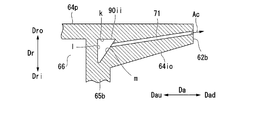
- a part of the axially upstream side Dau in the rear end face ejection passage 71 overlaps the rear side passage 90ii.
- the rear end face ejection passage 71 is opened at the formation surface m of the upstream side Dau in the axial direction with respect to the portion positioned on the most axial downstream side Dad of the passage cross section of the rear side passage 90ii.
- the formation surface m faces the gas path surface 64 p side, that is, the flow path side. Therefore, a part of the rear passage 90ii is present on the flow passage side of the rear end face ejection passage 71.
- the gas path surface 64p is effectively cooled over the entire passage length of the rear end face ejection passage 71.
- the gas path surface 64p is effectively cooled over the entire passage length of the rear end face ejection passage 71 with high cooling efficiency. That is, in the present embodiment, the rear end face ejection passage 71 having high cooling efficiency sufficiently contributes to the cooling of the gas path surface 64p over the entire passage length. Therefore, in the present embodiment, the axial downstream side Dad of the gas path surface 64p can be effectively cooled without increasing the flow rate of the cooling air Ac.
- the passage forming the rear side passage 90i as described above
- the cross-sectional shape of the rear side passage 90i may not have an unequal quadrilateral shape as long as the above-mentioned necessary conditions are satisfied.
- various cross-sectional shapes of the rear side passage will be described with reference to FIGS. 8 to 13.
- the cross-sectional shape of the rear side passage 90ia of the present modified example has a substantially isosceles trapezoidal shape. Therefore, the rear side passage 90ia is defined by a plurality of passage forming surfaces including the first forming surface 91a, the third forming surface 93a, the fourth forming surface 94a, and the fifth forming surface 95a.
- the plurality of sides forming the cross section of the rear side passage 90i the side included in the first formation surface 91a, the side included in the third formation surface 93a, the side included in the fourth formation surface 94a, and the fifth formation All sides included in the surface 95a are substantially straight.
- the first formation surface 91a, the third formation surface 93a, the fourth formation surface 94a, and the fifth formation surface 95a are all curved surfaces that extend in the circumferential direction Dc and gradually bend in the circumferential direction Dc. Similar to the first formation surface 91 of the above-described embodiment, the first formation surface 91a of this modification faces the radially inner side Dri, and gradually moves away from the gas path surface 64p toward the axially downstream side Dad.
- the fourth formation surface 94 a faces the axially downstream side Dad, and extends from the end of the axially upstream side Dau of the first formation surface 91 a to the radially inner side Dri.
- the fourth formation surface 94 a is substantially parallel to the inner surface of the rear wall 65 b facing the recess 66.
- the third formation surface 93a faces the radially outer side Dro, and gradually approaches the gas path surface 64p as it goes to the axially downstream side Dad, similarly to the third formation surface 93 of the above embodiment.
- the third formation surface 93a is substantially parallel to the outer opposite gas path surface 64io.
- the end of the axially upstream side Dau of the third forming surface 93a is connected to the end of the radially inner side Dri of the fourth forming surface 94a.
- the fifth formation surface 95 a faces the axially upstream side Dau, and extends from the end of the axially downstream side Dad of the third formation surface 93 a to the radially outer side Dro.
- the fifth formation surface 95a is substantially parallel to the fourth formation surface 94a.
- the end of the radially outer side Dro of the fifth forming surface 95a is connected to the end of the axially downstream side Dad of the first forming surface 91a. That is, in the present modification, the first formation surface 91 a and the fourth formation surface 94 a are directly connected, and the second formation surface 92 is formed between the first formation surface 91 and the fourth formation surface 94 as in the above embodiment. Does not exist.
- a fifth formation surface 95a exists between the third formation surface 93a and the first formation surface 91a.
- the rear end face ejection passage 71 is directed at the radially inner side Dri (the opposite flow path side), and is opened at the first formation surface 91a which gradually moves away from the gas path surface 64p toward the axial downstream side Dad. . Therefore, also in the present modification, the portion on the axially downstream side Dad of the gas path surface 64p can be effectively cooled without increasing the flow rate of the cooling air Ac.
- the cross-sectional shape of the rear side passage 90ib of this modification is substantially trapezoidal. Therefore, the rear passage 90ib is defined by a plurality of passage forming surfaces including the first forming surface 91b, the fourth forming surface 94b, the fifth forming surface 95b, and the sixth forming surface 96b.
- the plurality of sides forming the cross section of the rear side passage 90ib the side included in the first formation surface 91b, the side included in the fourth formation surface 94b, the side included in the fifth formation surface 95b, and the sixth formation All the sides included in the surface 96 b are substantially straight.
- the first formation surface 91b, the fourth formation surface 94b, the fifth formation surface 95b, and the sixth formation surface 96b are all curved surfaces that extend in the circumferential direction Dc and gradually bend in the circumferential direction Dc. Similar to the first formation surface 91 of the above-described embodiment, the first formation surface 91b of this modification faces the radially inner side Dri, and gradually moves away from the gas path surface 64p toward the axially downstream side Dad.
- the fourth formation surface 94 b faces the axially downstream side Dad, and extends from the end of the axially upstream side Dau of the first formation surface 91 b to the radially inner side Dri.
- the fourth formation surface 94 b is substantially parallel to the inner surface of the rear wall 65 b facing the recess 66.
- the sixth formation surface 96 b faces the radially outer side Dro and is substantially parallel to the gas path surface 64 p.
- the end of the sixth upstream forming face 96 b in the axial direction Dau is connected to the end of the fourth inner forming face 94 b on the radially inner side Dri.
- the fifth formation surface 95 b faces the axially upstream side Dau, and extends from the end of the axially downstream side Dad of the sixth formation surface 96 b to the radially outer side Dro.
- the fifth formation surface 95b is substantially parallel to the fourth formation surface 94b.
- the end of the radially outer side Dro of the fifth forming surface 95b is connected to the end of the axially downstream side Dad of the first forming surface 91b.
- the rear end face ejection passage 71 is directed at the radially inner side Dri (the opposite flow path side), and is opened at the first formation surface 91b which gradually moves away from the gas path surface 64p toward the axial downstream side Dad. . Therefore, also in the present modification, the portion on the axially downstream side Dad of the gas path surface 64p can be effectively cooled without increasing the flow rate of the cooling air Ac.
- the passage forming surface of the rear passage 90ib is required to be separated from the surface existing on the outside of the rear passage 90ib by the allowable distance D or more.
- the passage sectional area of the rear passage 90ib is required to be large in order to suppress the pressure loss in the process of the cooling air Ac flowing through the rear passage 90ib.
- the fourth formation surface 94 and 94a are substantially parallel to the inner surface facing the recess 66, which is the surface of the rear wall 65b.
- the third formation surfaces 93 and 93a are substantially parallel to the outer opposite gas path surface 64io.
- the fourth formation surface 94 b is substantially parallel to the inner surface facing the recess 66, which is the surface of the rear wall 65 b.
- the sixth formation surface 96b closest to the outer opposite gas path surface 64io is not parallel to the outer opposite gas path surface 64io.
- the other part of the sixth forming surface 96b is more than necessary from the outer opposite gas path surface 64io.
- the cross-sectional area of the rear passage 90ib decreases. Therefore, the above-mentioned embodiment and the first modification are superior to this modification in terms of increasing the cross-sectional area of the rear passage.
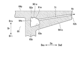
- the cross-sectional shape of the rear side passage 90ic of this modification is substantially in the shape of an equilateral triangle.
- the rear side passage 90ic is defined by a plurality of passage forming surfaces including the first forming surface 91c, the third forming surface 93c, and the fourth forming surface 94c.
- the side included in the first formation surface 91c, the side included in the third formation surface 93c, and the side included in the fourth formation surface 94c are all It is substantially straight.
- the first formation surface 91c, the third formation surface 93c, and the fourth formation surface 94c are all curved surfaces extending in the circumferential direction Dc and gradually bending in the circumferential direction Dc. Similar to the first formation surface 91 of the above-described embodiment, the first formation surface 91 c of the present modification faces the radially inner side Dri, and gradually moves away from the gas path surface 64 p toward the axial downstream side Dad. The fourth formation surface 94 c faces the axially downstream side Dad, and extends from the end of the axially upstream side Dau of the first formation surface 91 c to the radially inner side Dri. The fourth formation surface 94 c is substantially parallel to the inner surface of the rear wall 65 b facing the recess 66.
- the third formation surface 93 c faces the radially outer side Dro, and gradually approaches the gas path surface 64 p toward the axially downstream side Dad.
- the third formation surface 93 c is substantially parallel to the outer opposite gas path surface 64 io.
- the end of the axially upstream side Dau of the third formation surface 93 c is connected to the end of the radially inner side Dri of the fourth formation surface 94 c.
- the end of the axially downstream side Dad of the third formation surface 93c is connected to the end of the axially downstream side Dad of the first formation surface 91c. That is, in the present modification, the first formation surface 91 c and the fourth formation surface 94 c are directly connected, and the second formation surface 92 is formed between the first formation surface 91 and the fourth formation surface 94 as in the above embodiment. Does not exist.
- the rear end face ejection passage 71 is directed at the radially inner side Dri (the opposite flow path side), and opens at the first formation surface 91c gradually moving away from the gas path surface 64p toward the axial downstream side Dad. . Therefore, also in the present modification, the portion on the axially downstream side Dad of the gas path surface 64p can be effectively cooled without increasing the flow rate of the cooling air Ac. Therefore, the cross-sectional shape of the rear side passage does not have to be rectangular as described above, and even if it is triangular, the same effect as that of the above embodiment can be obtained.
- the corners formed by the one forming surface 91c are all acute angles. As described above, when the angle formed by the adjacent formation surfaces is an acute angle, the uneven flow of the cooling air Ac occurs near this angle, and the velocity of the flow of the cooling air Ac in the passage cross section of the rear passage 90ic Distribution occurs.
- the flow velocity of the cooling air Ac is large in the vicinity of the opening of the rear end face ejection passage 71 in the passage cross section of the rear passage 90ic, and the cooling air Ac along the first formation surface 91 in the passage cross section of the rear passage 90ic. Because the velocity distribution occurs in the flow of the air, the flow rate of the cooling air Ac flowing from the rear side passage 90ic to the rear end face ejection path 71 is suppressed more than in the above embodiment. For this reason, even when there are a plurality of corners formed by adjacent formation surfaces, it is preferable to reduce the number of acute angles as much as possible.
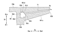
- the cross-sectional shape of the rear side passage 90 id of the present modified example has an unequal hexagon shape.
- the rear side passage 90 id is a plurality of passage forming surfaces including a first forming surface 91 d, a second forming surface 92 d, a third forming surface 93 d, a fourth forming surface 94 d, a fifth forming surface 95 d, and a sixth forming surface 96 d. It is defined.
- the side included in the surface 94c, the side included in the fifth forming surface 95d, and the side included in the sixth forming surface 96d are substantially straight.
- the first formation surface 91d, the second formation surface 92d, the third formation surface 93d, the fourth formation surface 94d, the fifth formation surface 95d, and the sixth formation surface 96d all extend in the circumferential direction Dc, and the circumferential direction Dc It is a curved surface that gradually bends toward it.
- the first formation surface 91 d of this modification faces the radially inner side Dri, and gradually moves away from the gas path surface 64 p toward the axial downstream side Dad.
- the second formation surface 92 d faces the radially inner side Dri, and extends from the end of the axially upstream side Dau of the first formation surface 91 d to the axially upstream side Dau.
- the second formation surface 92 d is substantially parallel to the gas path surface 64 p.
- the fourth formation surface 94 d faces the axially downstream side Dad, and extends from the end of the axially upstream side Dau of the second formation surface 92 d to the radially inner side Dri.
- the fourth formation surface 94 d is substantially parallel to the inner surface of the rear wall 65 b facing the recess 66.
- the sixth formation surface 96 d faces the radially outer side Dro, and is substantially parallel to the gas path surface 64 p and the second formation surface 92 d.
- the end of the sixth upstream forming face 96 d in the axial direction Dau is connected to the end of the fourth inner forming face 94 d on the radially inner side Dri.
- the third formation surface 93 d faces the radially outer side Dro, and gradually approaches the gas path surface 64 p toward the axially downstream side Dad.
- the end of the axially upstream side Dau of the third formation surface 93 d is connected to the end of the axially downstream side Dad of the sixth formation surface 96 d.
- the fifth formation surface 95 d faces the axially upstream side Dau, and extends from the end of the axially downstream side Dad of the third formation surface 93 d to the radially outer side Dro.
- the fifth forming surface 95 d is substantially parallel to the fourth forming surface 94 d.
- the end of the radially outer side Dro of the fifth forming surface 95d is connected to the end of the axially downstream side Dad of the first forming surface 91d.
- the rear end face ejection passage 71 is directed at the radially inner side Dri (the opposite flow path side), and opens at the first formation surface 91d which gradually moves away from the gas path surface 64p toward the axially downstream side Dad. . Therefore, also in the present modification, the portion on the axially downstream side Dad of the gas path surface 64p can be effectively cooled without increasing the flow rate of the cooling air Ac. Therefore, the cross-sectional shape of the rear side passage does not have to be rectangular as described above, and the same effect as that of the above embodiment can be obtained even if it is a polygonal shape having a larger number of sides than a square.
- the fourth formation surface 94 d is substantially parallel to the inner surface facing the recess 66 which is the surface of the rear wall 65 b and the outer opposite gas path
- the third formation surface 93 d is substantially parallel to the surface 64 io. Therefore, also in this modification, the passage cross-sectional area of the rear passage 90 id can be increased while separating the passage forming surface of the rear passage 90 id from the surface existing outside the rear passage 90 id by the allowable distance D or more. .
- any of the corners formed by the adjacent formation surfaces become obtuse.
- the rear side passage 90ie of this modification is defined by a plurality of passage forming surfaces including the first forming surface 91e, the second forming surface 92e, the third forming surface 93e, and the fourth forming surface 94e as in the above embodiment. .
- the side included in the second formation surface 92e, the side included in the third formation surface 93e, and the side included in the fourth formation surface 94e are all It is substantially straight.
- the second formation surface 92e, the third formation surface 93e, and the fourth formation surface 94e are all curved surfaces that extend in the circumferential direction Dc and gradually bend in the circumferential direction Dc.
- the first formation surface 91 e of this modification faces the radially inner side Dri, and gradually moves away from the gas path surface 64 p toward the axial downstream side Dad.
- the side included in the first formation surface 91e is a smooth curve convex outward from the inside to the rear side passage 90ie.
- the first formation surface 91e is also a curved surface that extends in the circumferential direction Dc and gradually bends in the circumferential direction Dc, similarly to the other formation surfaces 92e, 93e, and 94e. Also in this modification, the second formation surface 92e is substantially parallel to the gas path surface 64p.
- the rear end face ejection passage 71 is directed at the radially inner side Dri (the opposite flow path side), and is opened at the first formation surface 91 e gradually moving away from the gas path surface 64 p toward the axial downstream side Dad. . Therefore, also in the present modification, the portion on the axially downstream side Dad of the gas path surface 64p can be effectively cooled without increasing the flow rate of the cooling air Ac. Therefore, among the passage forming surfaces forming the rear side passage 90ie, even if the first forming surface 91e on which the rear end face ejection passage 71 is open is a curved surface, the same effect as the above embodiment can be obtained.
- the rear side passage 90if of this modification is defined by a plurality of passage forming surfaces including a first forming surface 91f, a fourth forming surface 94f, and a third forming surface 93f.
- the first formation surface 91f of this modification also faces the radially inner side Dri and gradually moves away from the gas path surface 64p toward the axially downstream side Dad, It is a smooth curved surface that is convex from the inside to the outside of the rear passage 90if.
- the fourth formation surface 94 f faces the axially downstream side Dad, and extends from the end of the axially downstream side Dad of the first formation surface 91 f to the radially inner side Dri.
- the fourth formation surface 94 f is a surface substantially parallel to the inner surface facing the recess 66, which is the surface of the rear wall 65 b. Similar to the third formation surface 93 of the above embodiment, the third formation surface 93f is directed radially outward Dro, and gradually approaches the gas path surface 64p toward the axially downstream side Dad, but from the inside of the rear passage 90if It is a smooth curved surface convex outward.
- the first formation surface 91 f and the third formation surface 93 f are smoothly continuous.
- the first formation surface 91 f and the third formation surface 93 f constitute one formation surface. Therefore, in the present modification, among the plurality of sides forming the passage cross section of the rear side passage 90if, all the sides included in the remaining forming surfaces 94f and 93f excluding the fourth forming surface 94f are curves.
- the rear end face ejection passage 71 is directed at the radially inner side Dri (the opposite flow path side), and is opened at the first formation surface 91f which gradually moves away from the gas path surface 64p toward the axial downstream side Dad. . Therefore, also in the present modification, the portion on the axially downstream side Dad of the gas path surface 64p can be effectively cooled without increasing the flow rate of the cooling air Ac. Therefore, among the plurality of sides forming the passage cross section of the rear side passage 90if, even if the side included in one formation surface is a straight line and all the sides included in the remaining formation surfaces are curves, the above embodiment. The same effect can be obtained.
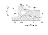
- the cross-sectional shape of the rear side passage 90ig of the first comparative example is substantially square or rectangular.
- the rear side passage 90ig is defined by four passage forming surfaces including the forming surface a, the forming surface b, the forming surface c, and the forming surface d.
- the side included in the formation surface a, the side included in the formation surface b, the side included in the formation surface c, and the side included in the formation surface d are Both are substantially straight.
- the formation surface a, the formation surface b, the formation surface c, and the formation surface d are all curved surfaces that extend in the circumferential direction Dc and gradually bend in the circumferential direction Dc.
- the forming surface a faces the radially inner side Dri and is substantially parallel to the gas path surface 64p.
- the forming surface b extends from the end of the axially upstream side Dau of the forming surface a to the radially inner side Dri.
- Forming surface b is substantially perpendicular to forming surface a, and substantially parallel to the inner surface of rear wall 65 b facing recess 66.
- the forming surface c faces the radially outer side Dro, and extends from the end of the radially inner side Dri of the forming surface b to the axially downstream side Dad.
- the formation surface c is substantially perpendicular to the formation surface b and substantially parallel to the gas path surface 64p and the formation surface a.
- the forming surface d extends from the end of the axially downstream side Dad of the forming surface c to the radially outer side Dro.
- the end of the radially outer side Dro of the forming surface d is connected to the end of the axially downstream side Dad of the forming surface a.
- the formation surface d is substantially perpendicular to the formation surface a and the formation surface c and substantially parallel to the formation surface b.
- the plurality of passage forming surfaces that define the rear side passage 90ig of the first comparative example do not include forming surfaces that face the radially inner side Dri and gradually move away from the gas path surface 64p toward the axially downstream side Dad. .
- the rear end face ejection passage 71 is opened at the forming surface d. Therefore, in the first comparative example, the end of the upstream end Dau in the axial direction of the rear end face ejection passage 71 is opened at the most axial downstream side Dad on the passage forming surface that forms the rear passage 90ig. It will be.
- the passage length of the rear end face ejection passage 71 having a high cooling effect is shorter than in the above-described embodiment and the above-described modifications.
- the cross-sectional shape of the rear side passage 90ih of the second comparative example is a shape in which two rectangles intersect.
- the rear side passage 90ih is defined by six passage forming surfaces including the forming surface e, the forming surface f, the forming surface g, the forming surface h, the forming surface i, and the forming surface j.
- the side included in the surface i and the side included in the forming surface j are substantially straight.
- the formation surface e, the formation surface f, the formation surface g, the formation surface h, the formation surface i, and the formation surface j are all curved surfaces that extend in the circumferential direction Dc and gradually bend in the circumferential direction Dc.
- the forming surface e faces the radially inner side Dri and is substantially parallel to the gas path surface 64p.
- the formation surface f extends from the end of the axially upstream side Dau of the formation surface e to the radially inner side Dri.
- the formation surface f is substantially perpendicular to the formation surface e and substantially parallel to the inner surface of the back wall 65 b facing the recess 66.
- the formation surface g faces the radially outer side Dro, and gradually approaches the gas path surface 64p as it proceeds to the axially downstream side Dad.
- the end of the axially upstream side Dau of the forming surface g is connected to the end of the radially inner side Dri of the forming surface f.
- the formation surface h extends radially outward Dro from the end of the formation surface g on the axially downstream side Dad.
- the formation surface h is substantially perpendicular to the formation surface g.
- the forming surface i faces the radially inner side Dri, and gradually approaches the gas path surface 64p as it proceeds to the axially downstream side Dad.
- the formation surface i is substantially parallel to the formation surface g.
- the end of the axially downstream side Dad of the forming surface i is connected to the end of the radially outer side Dro of the forming surface h.
- the forming surface j extends from the end of the axially upstream side Dau of the forming surface i to the radially outer side Dro and is substantially parallel to the forming surface f.
- the end of the radially outer side Dro of the forming surface j is connected to the end of the axially downstream side Dad of the forming surface e.
- the rear end face ejection passage 71 is opened at the formation surface j located on the upstream side Dau in the axial direction with respect to the portion on the most axial downstream side Dad of the rear side passage 90ih. Therefore, in the second comparative example, the passage length of the rear end face ejection passage 71 having a high cooling effect can be made longer as in the above embodiment and the above respective modifications. Moreover, in the second comparative example, there is a portion where the rear passage 90ih and the rear end face ejection passage 71 overlap when viewed from the radial direction Dr.
- the inner angles of the respective corners formed by the formation surfaces adjacent to each other are not 180 ° or less at all, and are formed by the formation surface i and the formation surface j
- the internal angle of the angle being made is greater than 180 °.
- the inside angle is the inside corner of the passage among the corners formed by the formation surfaces adjacent to each other.
- the cross-sectional shape of the rear side passage 90ii of the third comparative example has a triangular shape.
- the rear side passage 90ii is defined by three passage forming surfaces consisting of the forming surface k, the forming surface l, and the forming surface m.
- the side included in the forming surface k, the side included in the forming surface l, and the side included in the forming surface m are substantially straight lines. .
- the formation surface k, the formation surface l, and the formation surface m are all curved surfaces extending in the circumferential direction Dc and gradually bending in the circumferential direction Dc.
- the formation surface k faces the radially inner side Dri and is substantially parallel to the gas path surface 64p.
- the forming surface l extends from the end of the axially upstream side Dau of the forming surface k radially inward Dri.
- the forming surface l is substantially perpendicular to the forming surface k and substantially parallel to the inner surface of the rear wall 65 b facing the recess 66.
- the formation surface m faces the radially outer side Dro, and gradually approaches the gas path surface 64p toward the axially downstream side Dad.
- the end of the axially upstream side Dau of the forming surface m is connected to the end of the radially inner side Dri of the forming surface l.
- the end of the axially downstream side Dad of the forming surface m is connected to the end of the axially downstream side Dad of the forming surface k.
- the rear end face ejection passage 71 faces the radially outer side Dro, and opens at the forming surface m that gradually approaches the gas path surface 64p toward the axially downstream side Dad. Therefore, in the third comparative example, the rear end face ejection passage 71 is opened at a portion positioned on the upstream side Dau in the axial direction with respect to the portion on the downstream side Dad of the rear side passage 90ii. For this reason, in the third comparative example, the passage length of the rear end face ejection passage 71 having a high cooling effect can be made longer as in the above embodiment and the above respective modifications.
- the rear passage 90ii and the rear end face ejection passage 71 overlap with each other when viewed from the radial direction Dr.
- the rear end face ejection passage 71 opens at the forming surface m facing the radially outer side Dro. Therefore, in the third comparative example, the portion overlapping with the rear passage 90ii in the rear end face ejection passage 71 is located on the opposite side to the gas path surface 64p with reference to the rear passage 90ii. Therefore, in the third comparative example, as described above, the gas path surface 64p can not be effectively cooled over the entire passage length of the rear end face ejection passage 71 with high cooling efficiency.
- the cross-sectional shape of the rear side passage 90o in the outer shroud 60o of the present embodiment is an uneven square shape.
- the cross-sectional shape of the rear passage 90o is substantially the same as the shape obtained by inverting the cross-sectional shape of the rear passage 90i in the inner shroud 60i in the radial direction Dr.
- the rear side passage 90o is defined by a plurality of passage forming surfaces including a first forming surface 91g, a second forming surface 92g, a third forming surface 93g, and a fourth forming surface 94g.
- the side included in the first formation surface 91g, the side included in the second formation surface 92g, the side included in the third formation surface 93g, and the fourth formation All the sides included in the face 94g are substantially straight.
- the first formation surface 91g, the second formation surface 92g, the third formation surface 93g, and the fourth formation surface 94g are all curved surfaces that extend in the circumferential direction Dc and gradually bend in the circumferential direction Dc.
- the first formation surface 91 g faces the radially outer side Dro (the opposite flow path side), and gradually moves away from the gas path surface 64 p toward the axially downstream side Dad.
- the second formation surface 92g faces the radially outer side Dro (the opposite flow path side), and extends from the end of the axially upstream side Dau of the first formation surface 91g to the axially upstream side Dau.
- the second formation surface 92g is substantially parallel to the gas path surface 64p.
- the fourth formation surface 94g extends from the end of the axially upstream side Dau of the second formation surface 92g to the radially outer side Dro.
- the fourth formation surface 94 g is substantially parallel to the inner surface of the rear wall 65 b facing the recess 66.
- the third forming surface 93g faces the radially inner side Dri and is substantially parallel to the outer opposite gas path surface 64io.
- the end of the axially upstream side Dau of the third forming surface 93g is connected to the end of the radially outer side Dro of the fourth forming surface 94g. Further, the end of the axially downstream side Dad of the third forming surface 93g is connected to the end of the axially downstream side Dad of the first forming surface 91g.
- Each of the plurality of rear end face ejection passages 71 opens at the first formation surface 91g. Therefore, as for the outer shroud 60o, like the inner shroud 60i, it is possible to effectively cool the portion of the axially downstream side Dad of the gas path surface 64p without increasing the flow rate of the cooling air Ac.
- the cross-sectional shape of the rear side passage 90o in the outer shroud 60o does not need to have an unequal square shape as described above.
- various cross-sectional shapes of the rear side passage in the outer shroud 60o will be described with reference to FIGS.
- the rear passage 90oh in the present modification is triangular. Therefore, the rear passage 90oh is defined by a plurality of passage forming surfaces including the first forming surface 91h, the third forming surface 93h, and the fourth forming surface 94h. Among the plurality of sides forming the cross section of the rear side passage 90oh, the side included in the first formation surface 91h, the side included in the third formation surface 93h, and the side included in the fourth formation surface 94h are all , Substantially straight.
- the first formation surface 91 h, the third formation surface 93 h, and the fourth formation surface 94 h are all curved surfaces that extend in the circumferential direction Dc and gradually bend in the circumferential direction Dc.
- the first formation surface 91 h of this modification faces the radially outer side Dro (the opposite flow path side), and gradually moves away from the gas path surface 64 p as it goes to the axially downstream side Dad.
- the fourth formation surface 94 h extends from the end of the axially upstream side Dau of the first formation surface 91 h to the radially outer side Dro.
- the fourth formation surface 94 h is substantially parallel to the inner surface of the rear wall 65 b facing the recess 66.
- the third formation surface 93h faces the radially inner side Dri and is substantially parallel to the anti-gas path surface 64i.
- the end of the axially upstream side Dau of the third forming surface 93 h is connected to the end of the radially outer side Dro of the fourth forming surface 94 h.
- the end of the axially downstream side Dad of the third forming surface 93 h is connected to the end of the axially downstream side Dad of the first forming surface 91 h.
- the rear end face ejection passage 71 is directed at the radially outer side Dro (the opposite flow path side), and opens at the first formation surface 91 h which gradually moves away from the gas path surface 64 p toward the axially downstream side Dad. . Therefore, also in the present modification, the portion on the axially downstream side Dad of the gas path surface 64p can be effectively cooled without increasing the flow rate of the cooling air Ac. Therefore, the cross-sectional shape of the rear side passage 90oh does not have to be rectangular as described above, and even if it is triangular, the same effect as that of the above embodiment can be obtained.
- the cross-sectional shape of the rear passage is a polygonal shape having a larger number of sides than a quadrangle like the rear passage 90 id in the inner shroud 60i shown in FIG. 11, the same effect as the above embodiment can be obtained. be able to.
- the rear passage 90oi of the present modification is also defined by a plurality of passage formation surfaces including the first formation surface 91i, the third formation surface 93i, and the fourth formation surface 94i. .
- the side included in the third formation surface 93i and the side included in the fourth formation surface 94i are substantially straight lines.
- the third formation surface 93i and the fourth formation surface 94i are both curved surfaces that extend in the circumferential direction Dc and gradually bend in the circumferential direction Dc.
- the first formation surface 91i of this modification faces the radially outer side Dro (the opposite flow path side) and gradually moves away from the gas path surface 64p toward the axially downstream side Dad.
- the side included in the first formation surface 91i is a smooth curve convex outward from the inside of the rear passage 90oi.
- the rear end face ejection passage 71 is directed at the radially outer side Dro (the opposite flow path side), and is opened at the first formation surface 91i which is gradually moved away from the gas path surface 64p toward the axially downstream side Dad. . Therefore, also in the present modification, the portion on the axially downstream side Dad of the gas path surface 64p can be effectively cooled without increasing the flow rate of the cooling air Ac. Therefore, even if the side included in the first formation surface 91i among the sides forming the passage cross section of the rear side passage 90oi is a curve, the same effect as the above embodiment can be obtained. Further, as in the rear side passage 90if of the inner shroud 60i shown in FIG. 13, among the plurality of sides forming the passage cross section of the rear side passage, the side included in one forming surface is a straight line and the remaining forming surface is Even if all the included sides are curves, the same effect as the above embodiment can be obtained.
- FIG. 18 is a plan view of the inner shroud 60ia of the present modification as viewed from the radially outer side Dro
- FIG. 19 is a cross-sectional view taken along line XIX-XIX in FIG.
- a rear passage 90i and a plurality of rear end face ejection passages 71 are formed in the inner shroud 60ia of this modification as well.
- a plurality of first gas path surface ejection passages 72 are formed which communicate with the rear side passage 90i and open at the gas path surface 64p.
- Each of the plurality of first gas path surface ejection passages 72 is opened at a second formation surface 92 facing the radially inner side Dri (the opposite flow path side) among the passage formation surfaces that form the rear passage 90i.
- the openings at the gas path surface 64p in the plurality of first gas path surface ejection passages 72 are circumferentially Dc along the rear end face 62b of the inner shroud main body 61i in the region of the axial downstream side Dad from the rear edge 53 of the wing 51 Lined up.
- the inner shroud 60ia of this modification is further formed with a plurality of second gas path surface ejection passages 73 communicating with the inner cavity 67 and opening at the gas path surface 64p.
- the plurality of second gas path surface jet passages 73 are opened in the vicinity of the corner between the inner surface facing the recess 66 which is the surface of the rear wall 65 b and the bottom surface of the recess 66.
- the plurality of second gas path surface ejection passages 73 may be opened at the bottom surface side of the inner surface facing the inner cavity 67 (see FIG. 4) in the recess 66, which is the surface of the rear wall 65b. It may be opened in the bottom of the recess 66 at a portion on the rear wall 65 b side.
- the openings of the gas path surface 64p in the plurality of second gas path surface ejection passages 73 are axially downstream Dad from the rear edge portion 53 of the wing body 51 and from the openings in the gas path surface 64p in the first gas path surface ejection passages 72. Also in the region of the axially upstream side Dau, it is arranged in the circumferential direction Dc along the rear end surface 62b of the inner shroud main body 61i.
- the openings in the gas path surface 64p in the plurality of first gas path surface ejection passages 72 and the openings in the gas path surface 64p in the plurality of second gas path surface ejection passages 73 are all middle regions in the circumferential direction Dc in the gas path surface 64p. It is not formed in the ventral region of the circumferential ventral side Dcp in the gas path surface 64p and in the dorsal region of the circumferential back side Dcn in the gas path surface 64p. Further, all of the plurality of first gas path surface ejection passages 72 and the plurality of second gas path surface ejection passages 73 are directed to the gas path surface 64 p so as to gradually face the axially downstream side Dad as they approach the gas path surface 64 p. It is inclined. The significance of the middle region, the ventral region and the dorsal region will be described later.
- the cooling air Ac from the ventral passage 78p flows from the end of the circumferential ventral side Dcp of the back passage 90i into the back passage 90i.
- the cooling air Ac flows into the plurality of rear end face ejection passages 71 sequentially in the process of flowing to the circumferential back side Dcn in the rear side passage 90i.
- the cooling air Ac from the back side passage 78n flows into the back side passage 90i from the end of the circumferential back side Dcn of the back side passage 90i.
- the cooling air Ac flows into the plurality of rear end face ejection passages 71 sequentially in the process of flowing to the circumferential direction ventral side Dcp in the rear side passage 90i.
- the flow rate of the cooling air Ac flowing in the middle region of the circumferential direction Dc in the rear side passage 90i is smaller than the flow rate of the cooling air Ac flowing on both ends in the circumferential direction Dc in the rear side passage 90i.
- the flow velocity of the cooling air Ac flowing in the middle region in the circumferential direction in the rear passage 90i is equal to that in the rear passage 90i. It becomes smaller than the flow velocity of the cooling air Ac which flows in the both ends of circumferential direction Dc.
- the middle region of the circumferential direction Dc in the rear passage 90i is higher than the two ends in the circumferential direction Dc in the rear passage 90i. It becomes smaller.
- the cooling air Ac flowing through the rear side passage 90i is gradually heated in the process of flowing from the both end sides in the circumferential direction Dc to the middle region in the circumferential direction Dc. For this reason, the effect of convective cooling by the cooling air Ac flowing through the rear side passage 90i is lower in the middle region of the circumferential direction Dc than at both end sides of the circumferential direction Dc.
- the flow path length of the combustion gas G flowing along the back side surface 54 of the wing body 51 is longer than the flow path length of the combustion gas G flowing along the ventral side surface 55 of the wing body 51. For this reason, the flow velocity of the combustion gas G flowing along the back surface 54 of the wing body 51 is faster than the flow velocity of the combustion gas G flowing along the ventral surface 55 of the blade body 51. Further, the combustion gas G having flowed along the back surface 54 of the wing body 51 thereafter flows at a high flow velocity even in a portion near the rear end surface 62b in the gas path surface 64p and in the middle region of the circumferential direction Dc.
- the heat transfer coefficient between the combustion gas G and the gas path surface 64p is higher in a portion near the rear end face 62b in the gas path surface 64p and in the middle region in the circumferential direction Dc, and the combustion gas G is higher than other portions. It is easy to be heated.
- the plurality of first gas path surface ejection passages 72 and the plurality of second gas path surface ejection passages 73 are provided, but only one of the gas path surface ejection passages may be provided.
- the openings on the gas path surface 64p in the plurality of first gas path surface ejection passages 72 are arranged in a line in the circumferential direction Dc.
- the openings at the gas path surface 64p in the plurality of second gas path surface ejection passages 73 are also aligned in the circumferential direction Dc.
- the plurality of first gas path surface jet passages 72 are opened by the second formation surface 92 of the rear side passage 90i.
- the rear end face ejection passage 71 be opened at a position upstream in the axial direction Dau of the position of communication with the rear side passage.
- this modification is a modification of the inner shroud 60i
- the plurality of first gas path surface ejection passages 72 and / or the plurality of second ones are also applied to the outer shroud 60o as in the present modification.
- a gas path surface jet passage 73 may be provided.
- FIG. 20 is a cross-sectional view corresponding to the cross-sectional view along the line V-V in FIG. 4 showing the embodiment.
- a rear passage 90i and a plurality of rear end face ejection passages 71 are formed in the inner shroud 60ib of this modification as well.
- the rear side passage 90i of this modification is in communication with the inner cavity 67 through the ventral communication passage 74p and the back communication passage 74n.
- the ventral communication passage 74p opens to the outer cavity 66a or the inner cavity 67 in the vicinity of the corner between the surface facing the recess 66 of the rear wall 65b and the surface facing the recess 66 of the abdominal wall 65p.
- the vent-side communication passage 74p is connected to the end of the circumferential vent side Dcp in the rear passage 90i.
- the back communication passage 74n opens to the outer cavity 66a or the inner cavity 67 near the corner between the surface of the back wall 65b facing the recess 66 and the surface of the back wall 65n facing the recess 66.
- the back communication passage 74n is connected to the end of the circumferential back Dcn in the rear passage 90i.
- the gas path surface 64p can be obtained without increasing the flow rate of the cooling air Ac as in the above embodiment. It is possible to effectively cool the portion of the downstream side Dad of the
- a plurality of first gas path surface ejection passages 72 and / or a plurality of second gas path surface ejection passages 73 are provided. It is also good. Further, in the present modification, since the pressure of the cooling air Ac flowing from the outer cavity 66a through the impingement plate 81 and flowing into the inner cavity 67 is low, the communication passage 74n from the inner cavity 67, the vent communication passage 74p and the rear The differential pressure of the cooling air Ac flowing into the rear end face ejection passage 71 via the side passage 90i can not be sufficiently ensured, and the cooling capacity may be insufficient.
- the back communication passage 74n or the vent communication passage 74p is connected to the inner surface of the outer cavity 66a where the pressure of the cooling air Ac is higher than that of the inner cavity 67. Since a sufficient differential pressure can be secured, the lack of cooling capacity can be eliminated.
- this modification is a modification of the inner shroud 60i
- the outer shroud 60o is cooled from the vent communication passage 74p and the back communication passage 74n to the rear passage 90o as in the present embodiment. You may supply air Ac.
- FIG. 21 is a cross-sectional view corresponding to the cross-sectional view taken along the line V-V in FIG. 4 showing the embodiment.
- a rear passage 90i first side passage
- a plurality of rear end face ejection passages 71 are formed in the inner shroud 60ic of this modification as well.
- a region not including the edge with the back end surface 63n and the edge of the ventral end surface 63p is referred to as a middle region MP.
- a region including the edge with the back end surface 63n in the rear end surface 62b and adjacent to the middle region MP in the circumferential direction Dc (first direction) is referred to as a back region NP.
- a region including the edge with the ventral end surface 63p in the rear end surface 62b and being adjacent to the middle region MP in the circumferential direction Dc is referred to as a ventral region PP.
- openings of three or more rear end face ejection passages 71 aligned in the circumferential direction Dc may be formed. Further, it is assumed that the cross-sectional shapes of the plurality of rear end face ejection passages 71 are all circular and the inner diameters are the same. Therefore, the wetted edge lengths s of the plurality of end face ejection passages are the same.
- the wetted edge length s is the length of the wall surface in contact with the fluid in the passage cross section. For example, if the passage cross section is circular, the wetted edge length is the circumferential length of this circle.
- the distance between the openings of the rear end face ejection passages 71 in the middle region MP is p1.
- the spacing between the openings of the rear end face ejection passages 71 in the back side area NP and the spacing between the openings of the rear end face injection paths 71 in the ventral side area PP are p2.
- An interval p1 between the openings of the rear end face ejection passages 71 in the middle area MP is smaller than an interval p2 between the openings of the rear end face ejection paths 71 in the back side area NP and the ventral area PP.
- the ratio of the wetted edge length s of the plurality of rear end face ejection passages 71 to the interval p of the openings of the plurality of rear end face ejection passages 71 is defined as the opening density (s / p).
- the opening density of the plurality of rear end face ejection passages 71 in the middle region MP is (s / p1).
- the opening density of the plurality of rear end face ejection passages 71 in the ventral region PP and the dorsal region NP is (s / p 2).
- the opening density (s / p1) of the plurality of back end face ejection passages 71 in the middle region MP is the opening density (s s) of the plurality of back end surface ejection paths 71 in the abdominal region PP and the back side region NP. Higher than / p2).
- the opening density of the plurality of rear end surface ejection passages 71 in the middle region MP is set higher than the opening density of the plurality of rear end surface ejection passages 71 in the ventral region PP and the dorsal region NP.
- the cooling effect by the plurality of rear end face ejection passages 71 in the region MP is higher than the cooling effect by the plurality of rear end face ejection passages 71 in the ventral region PP and the back side region NP.
- the opening density of the plurality of rear end surface ejection passages 71 in the middle region MP is the opening density of the plurality of rear end surface ejection passages 71 in the abdominal region PP and the opening density of the plurality of rear end surface ejection passages 71 in the dorsal region NP. And may be higher than the aperture density of one region and the same as the aperture density of the other region.
- the opening density of the plurality of rear end face ejection passages 71 in the middle region MP may be changed in the middle region MP.
- the opening density of the plurality of back end face ejection passages 71 in the ventral region PP may also vary within the abdomen side region PP, and the opening density of the plurality of rear end face ejection passages 71 in the dorsal region NP It may change in the region NP.
- the spacing p of the openings of the plurality of rear end face ejection passages 71 in this area is It is smaller than the interval p.
- the wetted edge length s of the plural rear end face ejection passages 71 in this area is made longer than the wetted edge length s of the plural rear end face ejection passages 71 in the other area. May be
- a plurality of first gas path surface ejection passages 72 and / or a plurality of second gas path surface ejection passages 73 are provided. It is also good. Further, in the inner shroud 60ic of this modification as well as the inner shroud 60ib of the second modification, the cooling air Ac may be supplied from the vent-side communication passage 74p and the back-side communication passage 74n to the rear passage 90i. .
- this modification is a modification of the inner shroud 60i
- the opening density at the rear end face 62b of the plurality of rear end face ejection passages 71 is set to the outer shroud 60o as in the present modification. You may
- the above description is an example in the case where the rear side passage 90i is provided and the plurality of rear end face ejection passages 71 communicate with the rear side passage 90i.
- the same may be applied to the above. That is, among the passage-forming surfaces forming the ventral-side passage 78p and the back-side passage 78n, a plurality of sides are formed on the first formation surface which gradually moves away from the opposite gas path surface 64i.
- the end face ejection passage may be opened.
- the moving blade 150 of this embodiment includes a wing 151 extending in the radial direction Dr, a platform 160 formed on the radially inner side Dri of the wing 151, and a radially inner side Dri of the platform 160.
- the wing root 157 formed in The wing body 151 is disposed in the combustion gas flow path 49 (see FIG. 2).
- the platform 160 defines the position of the radially inner side Dri of the annular combustion gas passage 49.
- the platform 160 is a flow path forming plate that defines a portion of the combustion gas flow path 49.
- the wing 151 forms an airfoil.
- an end portion of the axially upstream side Dau forms a front edge portion 152
- an end portion of the axially downstream side Dad forms a rear edge portion 153.
- the circumferential back side Dcn of the moving blade 150 is the front side in the rotational direction of the rotor shaft 32.
- the circumferential back side Dcn of the stationary blade 50 is the rear side in the rotational direction of the rotor shaft 32.
- the circumferential back side Dcn of the moving blade 150 is opposite to the circumferential back side Dcn of the stationary blade 50 in the circumferential direction Dc.
- the platform 160 includes a plate-like platform main body 161 extending in the axial direction Da and the circumferential direction Dc, a rear projection 167 b projecting from the end of the axial downstream side Dad of the platform main body 161 to the axial downstream side Dad, And a front protrusion 167 f protruding from the end of the axially upstream side Dau to the axially upstream side Dau.
- the platform body 161 has a front end face 162f which is an end face of the axially upstream side Dau, a rear end face 162b which is an end face of the downstream side Dad, and a pair of circumferential end faces 163 facing mutually opposite sides in the circumferential direction Dc.
- a gas path surface 164p facing the radially outer side Dro and an opposite gas path surface 164i facing the radially inner side Dri are formed.
- the end face of the circumferential ventral side Dcp constitutes an abdominal end face 163p
- the end face of the circumferential back side Dcn constitutes a back end face 163n.
- the front end face 162 f and the rear end face 162 b are substantially parallel.
- the ventral end face 163p and the back end face 163n are substantially parallel. Therefore, the platform main body 161 has a parallelogram as shown in FIG. 24 when viewed from the radial direction Dr.
- the rotor blade 150 is formed with a plurality of wing air passages 175 extending in the radial direction Dc.
- Each of the wing air passages 175 is formed continuously from at least the wing 151 to the platform 160 among the wing 151, the platform 160 and the wing root 157.
- the plurality of wing air passages 175 are aligned along the wing centerline of the wing 151. Portions of adjacent wing air passages 175 communicate with each other in the radially outer part Dro within the wing 151 or in the radially inner part Dri of the platform 160.
- any one of the plurality of wing air passages 175 is formed continuously from the wing body 151, the platform 160, and the wing root 157, and is open at the end of the radially inner side Dri of the wing root 157. Cooling air Ac from the cooling air passage of the rotor shaft 32 (see FIG. 2) flows into this blade air passage 175 from this opening.
- the blade air passage 175 on the most axially upstream side Dau is taken as a first blade air passage 175a.
- the second wing air passage 175b and the third wing air passage 175c are arranged in this order in the axial downstream side Dad with reference to the first wing air passage 175a.
- the third wing air passage 175 c is formed continuously to the wing body 151, the platform 160, and the wing root 157, and opens at the end of the radially inner side Dri of the wing root 157.
- Each of the first wing air passage 175 a and the second wing air passage 175 b is formed continuously to the wing body 151 and the platform 160.
- the second wing air passage 175b is in communication with the radially outer side Dro of the third wing air passage 175c at the radially outer side Dro.
- the second wing air passage 175b is in communication with the radially inner side Dri of the first wing air passage 175a at the radially inner side Dri.
- the front edge 152 and the rear edge 153 of the wing body 151 are formed with a plurality of wing surface ejection passages 176 penetrating from the wing air passage 175 to the combustion gas passage 49.
- the wing body 151 is cooled in the process of the cooling air Ac flowing in the wing air passage 175. Further, the cooling air Ac that has flowed into the wing air passage 175 flows out from the wing surface ejection passage 176 into the combustion gas passage 49. Therefore, the leading edge 152 and the trailing edge 153 of the wing 151 are cooled in the process of the cooling air Ac flowing through the wing jet passage 176. Furthermore, a portion of the cooling air Ac that has flowed out of the wing surface ejection passage 176 into the combustion gas flow path 49 partially covers the surface of the wing 151 and also serves as film air.
- the platform main body 161 is formed with a ventral side passage 178p, a back side passage 178n, a rear side passage 190, and a plurality of rear end face ejection passages 171.
- the ventral passage 178p and the dorsal passage 178n are both in communication with the first wing air passage 175a of the plurality of wing air passages 175 most axially upstream Dau.
- the ventral passage 178p extends from the first wing air passage 175a toward the ventral side Dcp toward the ventral end surface 163p, and the end of the ventral side Dcp of the circumferential passage portion 173p.
- the back side passage 178n is a circumferential passage portion 173n extending from the first wing air passage 175a toward the back side Dcn toward the back side end surface 163n and an end of the back direction Dcn of the circumferential passage portion 173n in the circumferential direction.
- an axial passage portion 174 n extending in a direction having an axial direction Da component along the back end face 163 n.
- the rear passage 190 extends in the circumferential direction Dc along the rear end surface 162 b of the platform main body 161 on the downstream side Dad in the axial direction of the rear edge portion 153 of the wing 151.
- the end of the circumferential ventral side Dcp of the rear side passage 190 is in communication with the end of the axially downstream side Dad of the ventral side passage 178p.
- an end of the circumferential back side Dcn of the rear side passage 190 is in communication with an end of the axially downstream side Dad of the back side passage 178n.
- Each of the plurality of rear end face ejection passages 171 is in communication with the rear side passage 190.
- Each of the plurality of rear end face ejection passages 171 extends from the rear side passage 190 to the axially downstream side Dad and opens at the rear end surface 162 b of the platform main body 161.
- the plurality of rear end face ejection passages 171 are arranged in the circumferential direction Dc.
- the passage cross-sectional area of the rear side passage 190 is larger than the passage cross-sectional area of the rear end face ejection passage 171.
- the cross-sectional shape of the rear side passage 190 is basically the same as the cross-sectional shape of the rear side passage 90i of the inner shroud 60i in the vane 50 described with reference to FIG. That is, the cross-sectional shape of the rear side passage 190 has an unequal square shape.
- one passage forming surface faces the radially inner side Dri (the opposite flow path side) and gradually proceeds toward the axially downstream side Dad (end face side) It is a first formation surface 191 (see FIG. 23) which is separated from the gas path surface 164p.
- the plurality of rear end face ejection passages 171 open at the first formation surface 191.
- the passage length of the rear end face ejection passage 171 having a high cooling effect becomes long. Further, in the present embodiment, there is a portion where the rear passage 190 and the rear end face ejection passage 171 overlap when viewed from the radial direction Dr. Therefore, also in the moving blade 150 of the present embodiment, it is possible to effectively cool the portion on the axially downstream side Dad of the gas path surface 164p without increasing the flow rate of the cooling air Ac.
- the ventral passage 178p and the dorsal passage 178n are communicated with the first wing air passage 175a of the most axially upstream side Dau of the plurality of wing air passages 175, and the ventral passage 178p and the dorsal side are communicated.
- the rear passage 190 is in communication with the passage 178n.
- the vent passage and the back passage are communicated with the second blade air passage 175b or the third blade air passage 175c, and the vent passage and the back passage are
- the side passage 190 may be in communication.
- the cross-sectional shape of the rear side passage 190 in the rotor blade 150 of the present embodiment is the same as the cross-sectional shape of the rear side passage 90i of the inner shroud 60i in the vane 50 described with reference to FIG.
- the cross-sectional shape of the rear side passage 190 in the rotor blade 150 may be various shapes as in the cross-sectional shape of the rear side passage in the stator blade 50 using FIGS. 8 to 13.
- first gas path surface jet passage may be communicated with the rear side passage 190 of the rotor blade 150 in the same manner as the inner shroud 60ia shown in FIGS. 18 and 19. That is, a first gas path surface jet passage may be provided which communicates with the rear side passage 190 and opens at the gas path surface 164 p of the platform 160. Furthermore, the opening density of the plurality of rear end face ejection passages 171 of the moving blade 150 is the same as the inner shroud 60ic shown in FIG. 21 in the middle region MP, the back region NP and the ventral region in the rear end surface 162b of the platform body 161. You may change by PP.
- the above description is an example in which the rear side passage 190 is provided, and the plurality of rear end face ejection passages 171 are communicated with the rear side passage 190.
- the plurality of side end surface ejection passages opened at the circumferential end surface are communicated with the ventral side passage 178p and the dorsal side passage 178n. That is, among the passage forming surfaces forming the ventral side passage 178p and the back side passage 178n, a plurality of side end surfaces are first forming surfaces which gradually move away from the opposite gas path surface 164i as the flow path side is turned to approach the circumferential end face.
- the jet passage may be opened.
- the split ring 250 is located on the radially outer side Dro of the moving blade 34 and faces the moving blade 34 in the radial direction Dr.
- the plurality of split rings 250 are arranged in the circumferential direction Dc, and configured annularly around the axis Ar.
- the split ring 250 defines the edge of the radially outer side Dro of the annular combustion gas passage 49. Therefore, this division
- segmentation ring 250 comprises a flow-path formation board.
- the split ring 250 has a plate-like split ring main body 261 and a peripheral wall 265. Similarly to the inner shroud main body 61i of the stationary blade 50, the split ring main body 261 is also formed of a front end face 262f, a rear end face 262b, a pair of circumferential end faces 263, a gas path surface 264p, and an anti gas path surface 264i. There is.
- the split ring main body 261 has a rectangular or square shape when viewed from the radial direction Dr.
- the front side in the rotational direction of the turbine rotor 31 is referred to as a rotational direction front side Dca
- the rear side in the rotational direction of the turbine rotor 31 is referred to as a rotational direction rear side Dcr
- the circumferential end face of the rotation direction front side Dca is referred to as a rotation front end face 263a
- the circumferential end face of the rotation direction rear side Dcr is referred to as a rotation rear end face 263r.
- the circumferential wall 265 protrudes from the opposite gas path surface 264i of the split ring main body 261 to the radially outer side Dro.
- the circumferential wall 265 is provided along the end face of the split ring main body 261.
- the circumferential wall 265 has a front wall 265 f and a rear wall 265 b facing each other in the axial direction Da, and a pair of side walls 265 a and 265 r facing each other in the circumferential direction Dc.
- the front wall 265 f is provided along the front end face 262 f of the split ring main body 261.
- the rear wall 265 b is provided along the rear end surface 262 b of the split ring main body 261.
- one side wall forms a rotation front side wall 265a provided along the rotation front end face 263a, and the other side wall is provided along the rotation rear side end face 263r It constitutes a rotating rear side wall 265r.
- the front wall 265 f and the rear wall 265 b both protrude to the radially outer side Dro more than the pair of side walls 265 a and 265 r with respect to the split ring main body 261, and form a hook portion.
- the hook portion is attached to the heat shield ring 43 described with reference to FIG. As shown in FIG.
- a seal groove 268 which is recessed in the rotational direction rear side Dcr and extends in the axial direction Da is formed in the rotational front side wall 265a. Further, a seal groove 268 which is recessed in the rotational direction front side Dca and extends in the axial direction Da is formed in the rotational rear side wall 265r. A seal plate 269 is fitted in the seal groove 268.
- a recessed portion 266 recessed toward the radially inner side Dri is formed by the split ring main body 261 and the peripheral wall 265.
- the split ring 250 further includes an impingement plate 281.
- the impingement plate 281 divides the space in the recess 266 into the area of the radially outer side Dro and the inner cavity 267 which is the area of the radially inner side Dri.
- the impingement plate 281 is formed with a plurality of through holes 282 penetrating in the radial direction Dr. A portion of the cooling air Ac present on the radially outer side Dro of the split ring 250 flows into the inner cavity 267 through the through hole 282 of the impingement plate 281.
- the front passage 240 extends in the circumferential direction Dc along the front end face 262f of the split ring main body 261, as shown in FIGS.
- the plurality of front communication passages 276 communicate the inner cavity 267 with the front passage 240.
- the plurality of front communication passages 276 extend in the axial direction Da.
- An end of the plurality of front communication passages 276 in the axial direction Dau is connected to the front passage 240.
- the end of the axially downstream side Dad of the plurality of front communication paths 276 is in communication with the inner cavity 267.
- an end of the plurality of front communication paths 276 in the axial direction on the downstream side Dad is open in the vicinity of the corner between the inner surface facing the recess 266 and the bottom surface of the recess 266.
- the plurality of rear end face ejection passages 277 extend in the axial direction Da.
- the ends of the plurality of rear end face ejection passages 277 in the axial direction Dau communicate with the front side passage 240.
- the ends of the plurality of rear end face ejection passages 277 in the axial direction downstream side Dad are open at the rear end face 262 b of the split ring main body 261.
- the passage cross-sectional area of the front side passage 240 is larger than the passage cross-sectional area of the rear end face ejection passage 277.
- the cooling air Ac from the front communication passage 276 collides with a part of the passage forming surface that forms the front passage 240, and performs impingement cooling on a part of the passage forming surface.
- the cooling air Ac flows from the front passage 240 into the plurality of rear end face ejection passages 277.
- the cooling air Ac convectively cools the portion along the gas path surface 264 p of the split ring main body 261 in the process of flowing through the rear end face ejection passage 277.
- the cooling air Ac flows out of the opening of the rear end surface 262b.
- the rotation front passage 290 extends in the axial direction Da along the rotation front end face 263a of the split ring main body 261, as shown in FIGS.
- the plurality of rotational front communication passages 278 communicate the inner cavity 267 with the rotational front passage 290.
- the plurality of rotating front communication paths 278 extend in the circumferential direction Dc.
- the end of the rotation direction front Dca of the plurality of rotation front communication passages 278 is connected to the rotation front passage 290. Further, the end in the rotational direction rear side Dcr of the plurality of rotational front communication paths 278 communicate with the inner cavity 267.
- the end of the rotation direction rear side Dcr of the plurality of rotation front communication paths 278 is the surface of the rotation front side wall 265 a and is open near the corner between the inner surface facing the recess 266 and the bottom of the recess 266 doing.
- the plurality of side end ejection passages 271 extend in the circumferential direction Dc.
- the end of the rotational direction rear side Dcr of the plurality of side end face ejection passages 271 is in communication with the rotational front side passage 290.
- the ends of the plurality of side end face ejection passages 271 in the rotational direction front side Dca are open at the rotation front end face 263 a of the split ring main body 261.
- the passage cross-sectional area of the rotation front passage 290 is larger than the passage cross-sectional area of the rotation front communication passage 278 and the passage cross-sectional area of the side end jet passage 271.
- the cross-sectional shape of the rotation front passage 290 has an irregular pentagonal shape. Therefore, the rotation front passage 290 is defined by a plurality of passage forming surfaces including a first forming surface 291, a second forming surface 292, a fourth forming surface 294, a fifth forming surface 295, and a sixth forming surface 296. .
- the side included in the first formation surface 291, the side included in the second formation surface 292, the side included in the fourth formation surface 294, the fifth formation Any of the sides included in the surface 295 and the sides included in the sixth forming surface 296 are substantially straight.
- the first formation surface 291, the second formation surface 292, the fourth formation surface 294, the fifth formation surface 295, and the sixth formation surface 296 are all planes extending in the axial direction Da.
- the first formation surface 291 faces the radially outer side Dro (the opposite flow path side) and gradually moves away from the gas path surface 264p as it approaches the end face side which is the side closer to the rotation front end face 263a which is the first end face.
- the second formation surface 292 extends from the end of the rotation direction rear side Dcr of the first formation surface 291 to the rotation direction rear side Dcr.
- the second formation surface 292 is substantially parallel to the gas path surface 264p.
- the fourth formation surface 294 extends from the end of the rotation direction rear side Dcr of the second formation surface 292 to the radially outer side Dro.
- the fourth formation surface 294 is parallel to the surface of the rotation front side wall 265 a and the inner surface facing the recess 266.
- the sixth formation surface 296 extends from the end of the radially outer side Dro of the fourth formation surface 294 to the front side Dca in the rotational direction.
- the sixth formation surface 296 is substantially parallel to the gas path surface 264 p and the second formation surface 292.
- the fifth forming surface 295 extends from the end of the rotational direction front side Dca of the sixth forming surface 296 radially inward Dri.
- the fifth forming surface 295 is substantially parallel to the fourth forming surface 294.
- An end of the fifth formation surface 295 radially inward Dri is connected to an end of the first formation surface 291 in the rotation direction front Dca.
- the rotation front communication passage 278 is opened at the fourth formation surface 294 among the passage formation surfaces that form the rotation front passage 290.
- the side end face ejection passage 271 is opened at the first formation surface 291 of the passage formation surfaces that form the rotation front passage 290.
- the cooling air Ac cools a portion along the rotation front passage 290 of the split ring main body 261 in the process of flowing through the rotation front passage 290.
- the cooling air Ac flows from the rotation front passage 290 into the plurality of side end face ejection passages 271.
- the cooling air Ac convectively cools a portion in the rotational direction front side Dca in the gas path surface 264 p of the split ring main body 261 in the process of flowing through the side end face ejection passage 271.
- the cooling air Ac flows out from the opening of the rotation front end face 263 a of the split ring main body 261.
- the effect of cooling by the cooling air Ac flowing through the side end face ejection passage 271 is higher than the effect of cooling by the cooling air Ac flowing through the rotating front passage 290.
- the side end face ejection passage 271 faces the radially outer side Dro (the opposite flow path side), and opens at a first formation surface 291 which gradually moves away from the gas path surface 264p as it goes to the rotation direction front side Dca (end surface side). For this reason, in the present embodiment, the passage length of the side end face ejection passage 271 having a high cooling effect becomes long. Therefore, in the split ring 250 of the present embodiment, similarly to the inner shroud 60i described above, it is possible to effectively cool the portion of the gas path surface 264p in the rotational direction front Dca without increasing the flow rate of the cooling air Ac. it can.
- the cross-sectional shape of the rotation front passage 290 in the split ring 250 of the present embodiment may be various shapes as in the cross-sectional shape of the rear passage 90i in the stationary blade 50 shown in FIGS. 7 to 13.
- the split ring 250 of the present embodiment communicates with the rotation front passage 290 in the same manner as the inner shroud 60ia shown in FIGS. 18 and 19 with respect to the rotation front passage 290 in the split ring 250.
- the first gas path surface jet passage may be opened to the gas path surface 264p.
- the split ring 250 a of the present variation is formed with a front passage 240 a and a plurality of front communication passages 276.
- a plurality of front end face ejection passages 249 are further formed in the split ring 250 a of this modification.
- the plurality of front end ejection passages 249 extend in the axial direction Da.
- the ends of the plurality of front end face ejection passages 249 in the axial direction downstream side Dad are in communication with the front side passage 240 a.
- the end of the plurality of front end face ejection passages 249 in the axial direction Dau is open at the front end face 262 f of the split ring main body 261.
- the passage cross-sectional area of the front passage 240 a is larger than the cross-sectional area of the front end face ejection passage 249.
- the cross-sectional shape of the front side passage 240a of the present modification is trapezoidal. Therefore, the front side passage 240 a is defined by a plurality of passage forming surfaces including the first forming surface 241, the second forming surface 242, the fourth forming surface 244, and the sixth forming surface 246. Among the plurality of sides forming the cross section of the front passage 240a, the side included in the first formation surface 241, the side included in the second formation surface 242, the side included in the fourth formation surface 244, the sixth formation surface All sides included in 246 are substantially straight. The first formation surface 241, the second formation surface 242, the fourth formation surface 244, and the sixth formation surface 246 are all curved surfaces that extend in the circumferential direction Dc and gradually bend in the circumferential direction Dc.
- the first formation surface 241 faces the radially outer side Dro (the opposite flow path side) and gradually moves away from the gas path surface 264p as it approaches the end face side which is the side approaching the front end face 262f which is the first end face.
- the second formation surface 242 extends from the end of the axially downstream side Dad of the first formation surface 241 to the axially downstream side Dad.
- the second formation surface 242 is substantially parallel to the gas path surface 264p.
- the fourth formation surface 244 extends from the end of the axially downstream side Dad of the second formation surface 242 to the radially outer side Dro.
- the fourth formation surface 244 is parallel to the inner surface of the front wall 265 f facing the recess 266.
- the sixth forming surface 246 extends from the end of the radially outer side Dro of the fourth forming surface 244 to the axially upstream side Dau.
- the sixth formation surface 246 is substantially parallel to the gas path surface 264 p and the second formation surface 242.
- the end of the sixth upstream forming face 246 in the axial direction Dau is connected to the end of the first upstream forming face 241 in the axial direction Dau.
- the front communication passage 276 opens at the fourth formation surface 244 of the passage formation surfaces that form the front passage 240 a.
- the rear end face ejection passage 277 is also open at the fourth formation surface 244 among the passage formation surfaces that form the front passage 240 a.
- the front end face ejection passage 249 is opened at the first formation surface 241 among the passage formation surfaces that form the front passage 240 a.
- a part of the cooling air Ac that has flowed into the front passage 240 a flows into the plurality of rear end face ejection passages 277 as in the above embodiment.
- the other part of the cooling air Ac flowing into the front passage 240 a flows into the front end face ejection passage 249.
- the cooling air Ac convectively cools a portion of the axially upstream side Dau in the gas path surface 264p of the split ring main body 261.
- the cooling air Ac flows out of the opening of the front end face 262 f of the split ring main body 261.
- the front end face ejection passage 249 is directed at the radially outer side Dro (the opposite flow path side), and is opened at a first formation surface 241 which gradually moves away from the gas path surface 264p as it goes to the axially upstream side Dau (end surface side). For this reason, in the present modification, the passage length of the front end face ejection passage 249 having a high cooling effect becomes long. Therefore, in the split ring 250a of this modification, the portion on the upstream side Dau in the axial direction of the gas path surface 264p can be effectively cooled without increasing the flow rate of the cooling air Ac.
- the cross-sectional shape of the front passage 240a in the split ring 250a of this modification may be various shapes as in the cross-sectional shape of the rear passage 90i in the stator blade 50 shown in FIGS.
- split ring 250a of the present embodiment has one end rotated forward with respect to the front passage 240a of the split ring 250a of this modification, as in the first modification of the inner shroud 60ia shown in FIGS.
- a first gas path surface jet passage may be provided which is in communication with the passage 290 and whose other end is open to the gas path surface 264p.
- the flow path forming plate described above is the inner shroud 60 i and the outer shroud 60 o of the stator blade 50, the platform 160 of the rotor blade 150, and the split ring 250.
- an intermediate product matching the outer shape of the flow path forming plate is formed (S1: outer shape forming step).
- a mold is formed in which an internal space conforming to the outer shape of the flow path forming plate is formed.
- the mold is formed, for example, by the lost wax method.
- molten metal is poured into the mold.
- a core matching the shape of the space is set in the mold and then the molten metal is poured.
- the molten metal hardens, an intermediate product is produced.
- the core is set in the mold, after the molten metal hardens, the core is dissolved with a chemical.
- a gas path surface, an anti-gas path surface, various end surfaces, and the like that form the outer surface of the flow path forming plate are formed.
- a first side passage is formed between the gas path surface of the intermediate product and the opposite gas path surface, extending in the direction along the first end surface which is a part of the end surface, and through which the cooling air Ac flows (S2: side passage Formation process).
- the first end surface is, for example, the rear end surface 62b of the inner shroud 60i in the above embodiment.
- the first side passage is, for example, the rear side passage 90i of the inner shroud 60i in the above embodiment.
- this side passage forming step (S2) as a part of the passage forming surface forming the first side passage, the side facing the opposite flow path side which is the side opposite to the gas path surface with reference to the gas path surface
- the first formation surface is formed to gradually move away from the gas path surface as the
- the first side passage can be formed, for example, by subjecting the intermediate product to electrical discharge machining, electrolytic processing, machining, or the like. Moreover, when casting an intermediate product, it is also possible to set a core matching the shape of the first side passage in the mold and to form the first side passage in the process of casting the intermediate product. In this case, the side passage forming step (S2) is performed in the outer shape forming step (S1) described above. In the side passage forming step (S2), other passages may be formed at the same time.
- a plurality of end surface ejection passages communicating with the first side passage and opened at the first end surface are formed (S3: ejection passage forming step).
- the end surface ejection passage is the rear end surface ejection passage 71 of the inner shroud 60i in the above embodiment.
- the ejection passage forming step (S3) the plurality of end surface ejection passages are formed such that the passage sectional area of the plurality of end surface ejection passages is smaller than the passage sectional area of the first side passage.
- a plurality of end face ejection passages are opened at the first formation surface of the first side passage.
- the end face ejection passage can be formed, for example, by subjecting the intermediate product to electric discharge machining, electrolytic machining, machining, or the like.
- other passages may be formed together.
- the intermediate product having undergone the side passage forming step (S2) and the jet passage forming step (S3) is subjected to a finishing process to complete a flow path forming plate (S4: finishing step).
- finishing step (S4) for example, the outer surface of the intermediate product is polished by machining or the like. Also, if necessary, a heat resistant coating is applied to the outer surface of the intermediate product.
- the portion on the first end face side in the gas path surface of the flow path forming plate can be effectively cooled.
Landscapes
- Engineering & Computer Science (AREA)
- Mechanical Engineering (AREA)
- General Engineering & Computer Science (AREA)
- Chemical & Material Sciences (AREA)
- Combustion & Propulsion (AREA)
- Architecture (AREA)
- Turbine Rotor Nozzle Sealing (AREA)
Priority Applications (5)
| Application Number | Priority Date | Filing Date | Title |
|---|---|---|---|
| KR1020187022598A KR102192874B1 (ko) | 2016-03-11 | 2017-03-03 | 유로 형성판, 이것을 구비하는 날개, 이것을 구비하고 있는 가스 터빈, 및 유로 형성판의 제조 방법 |
| US16/074,943 US10605102B2 (en) | 2016-03-11 | 2017-03-03 | Flow path forming plate, vane including this flow path forming plate, gas turbine including this vane, and manufacturing method of flow path forming plate |
| KR1020207019598A KR102235821B1 (ko) | 2016-03-11 | 2017-03-03 | 유로 형성판, 이것을 구비하는 날개, 이것을 구비하고 있는 가스 터빈, 및 유로 형성판의 제조 방법 |
| CN201780010337.2A CN108603411B (zh) | 2016-03-11 | 2017-03-03 | 流路形成板、具备该流路形成板的叶片、具备该叶片的燃气轮机及流路形成板的制造方法 |
| EP17763125.6A EP3388628B1 (en) | 2016-03-11 | 2017-03-03 | Flow path forming plate, blade provided with same, gas turbine provided with same, and method for manufacturing flow path forming plate |
Applications Claiming Priority (2)
| Application Number | Priority Date | Filing Date | Title |
|---|---|---|---|
| JP2016-048765 | 2016-03-11 | ||
| JP2016048765A JP6725273B2 (ja) | 2016-03-11 | 2016-03-11 | 翼、これを備えているガスタービン |
Publications (1)
| Publication Number | Publication Date |
|---|---|
| WO2017154785A1 true WO2017154785A1 (ja) | 2017-09-14 |
Family
ID=59790387
Family Applications (1)
| Application Number | Title | Priority Date | Filing Date |
|---|---|---|---|
| PCT/JP2017/008548 Ceased WO2017154785A1 (ja) | 2016-03-11 | 2017-03-03 | 流路形成板、これを備える翼、これを備えているガスタービン、及び流路形成板の製造方法 |
Country Status (7)
| Country | Link |
|---|---|
| US (1) | US10605102B2 (enExample) |
| EP (1) | EP3388628B1 (enExample) |
| JP (1) | JP6725273B2 (enExample) |
| KR (2) | KR102235821B1 (enExample) |
| CN (1) | CN108603411B (enExample) |
| TW (1) | TWI653387B (enExample) |
| WO (1) | WO2017154785A1 (enExample) |
Cited By (1)
| Publication number | Priority date | Publication date | Assignee | Title |
|---|---|---|---|---|
| US11834962B2 (en) | 2019-05-17 | 2023-12-05 | Mitsubishi Power, Ltd. | Turbine stator vane, gas turbine, and method of producing turbine stator vane |
Families Citing this family (15)
| Publication number | Priority date | Publication date | Assignee | Title |
|---|---|---|---|---|
| WO2016152573A1 (ja) * | 2015-03-26 | 2016-09-29 | 三菱日立パワーシステムズ株式会社 | 翼、及びこれを備えているガスタービン |
| JP6308710B1 (ja) * | 2017-10-23 | 2018-04-11 | 三菱日立パワーシステムズ株式会社 | ガスタービン静翼、及びこれを備えているガスタービン |
| US11187092B2 (en) * | 2019-05-17 | 2021-11-30 | Raytheon Technologies Corporation | Vane forward rail for gas turbine engine assembly |
| JP7289745B2 (ja) * | 2019-07-11 | 2023-06-12 | 三菱重工業株式会社 | 動翼、及びこれを備えている軸流回転機械 |
| US20210246829A1 (en) * | 2020-02-10 | 2021-08-12 | General Electric Company | Hot gas path components including aft end exhaust conduits and aft end flanges |
| JP6799702B1 (ja) | 2020-03-19 | 2020-12-16 | 三菱パワー株式会社 | 静翼及びガスタービン |
| JP7461213B2 (ja) * | 2020-05-19 | 2024-04-03 | 三菱重工業株式会社 | 静翼、静翼セグメント、軸流流体機械、静翼セグメントの製造補助装置、静翼セグメントの製造方法 |
| JP2022061204A (ja) * | 2020-10-06 | 2022-04-18 | 三菱重工業株式会社 | ガスタービン静翼 |
| JP7530307B2 (ja) * | 2021-01-22 | 2024-08-07 | 三菱重工業株式会社 | 流路形成板、これを備える翼及びガスタービン、並びに、流路形成板の製造方法 |
| US12385403B2 (en) | 2021-11-29 | 2025-08-12 | Mitsubishi Heavy Industries, Ltd. | Turbine stator vane |
| WO2023147117A1 (en) | 2022-01-28 | 2023-08-03 | Raytheon Technologies Corporation | Cooled vane with forward rail for gas turbine engine |
| WO2023147119A1 (en) | 2022-01-28 | 2023-08-03 | Raytheon Technologies Corporation | Cooled vane with forward rail for gas turbine engine |
| US12331662B2 (en) * | 2022-11-16 | 2025-06-17 | Mitsubishi Heavy Industries, Ltd. | Structure of cooling turbine vane shroud and manufacturing method thereof |
| US12305532B2 (en) | 2022-11-16 | 2025-05-20 | Mitsubishi Heavy Industries, Ltd. | Cooling method and structure of vane of gas turbine |
| WO2025110061A1 (ja) * | 2023-11-21 | 2025-05-30 | 三菱パワー株式会社 | 流路形成板、静翼、及びガスタービン |
Citations (8)
| Publication number | Priority date | Publication date | Assignee | Title |
|---|---|---|---|---|
| JPH04231605A (ja) * | 1990-05-31 | 1992-08-20 | General Electric Co <Ge> | ガスタ―ビンエンジン用ノズルアセンブリ |
| JP2003027902A (ja) * | 2001-07-11 | 2003-01-29 | Mitsubishi Heavy Ind Ltd | ガスタービン静翼 |
| JP2005163791A (ja) * | 2003-12-04 | 2005-06-23 | General Electric Co <Ge> | タービンノズルセグメントの側壁を対流冷却するための方法及び装置 |
| JP2009162227A (ja) * | 2007-12-29 | 2009-07-23 | General Electric Co <Ge> | タービンノズル区画体の修繕方法 |
| JP2009299601A (ja) * | 2008-06-13 | 2009-12-24 | Mitsubishi Heavy Ind Ltd | タービン静翼構造 |
| JP2012107620A (ja) * | 2010-11-17 | 2012-06-07 | General Electric Co <Ge> | ターボ機械静翼、及びターボ機械静翼を冷却する方法 |
| JP2015017607A (ja) * | 2013-07-08 | 2015-01-29 | ゼネラル・エレクトリック・カンパニイ | ガスタービンのためのシュラウドブロックセグメント |
| US20150192020A1 (en) * | 2014-01-08 | 2015-07-09 | General Electric Company | Turbomachine including a component having a trench |
Family Cites Families (20)
| Publication number | Priority date | Publication date | Assignee | Title |
|---|---|---|---|---|
| US4571935A (en) * | 1978-10-26 | 1986-02-25 | Rice Ivan G | Process for steam cooling a power turbine |
| JP2851577B2 (ja) | 1996-02-26 | 1999-01-27 | 三菱重工業株式会社 | ガスタービン静翼シュラウドにおける冷却空気流路の加工方法 |
| US6382906B1 (en) * | 2000-06-16 | 2002-05-07 | General Electric Company | Floating spoolie cup impingement baffle |
| US6761529B2 (en) | 2002-07-25 | 2004-07-13 | Mitshubishi Heavy Industries, Ltd. | Cooling structure of stationary blade, and gas turbine |
| US9121609B2 (en) * | 2008-10-14 | 2015-09-01 | General Electric Company | Method and apparatus for introducing diluent flow into a combustor |
| US8567199B2 (en) * | 2008-10-14 | 2013-10-29 | General Electric Company | Method and apparatus of introducing diluent flow into a combustor |
| KR101366908B1 (ko) * | 2009-08-24 | 2014-02-24 | 미츠비시 쥬고교 가부시키가이샤 | 분할환 냉각 구조 및 가스 터빈 |
| JP4634528B1 (ja) | 2010-01-26 | 2011-02-16 | 三菱重工業株式会社 | 分割環冷却構造およびガスタービン |
| US8550778B2 (en) * | 2010-04-20 | 2013-10-08 | Mitsubishi Heavy Industries, Ltd. | Cooling system of ring segment and gas turbine |
| US8388304B2 (en) * | 2011-05-03 | 2013-03-05 | Siemens Energy, Inc. | Turbine airfoil cooling system with high density section of endwall cooling channels |
| GB201205663D0 (en) * | 2012-03-30 | 2012-05-16 | Rolls Royce Plc | Effusion cooled shroud segment with an abradable system |
| US9243509B2 (en) * | 2012-09-04 | 2016-01-26 | General Electric Company | Stator vane assembly |
| WO2014189873A2 (en) * | 2013-05-21 | 2014-11-27 | Siemens Energy, Inc. | Gas turbine ring segment cooling apparatus |
| JP6466647B2 (ja) * | 2014-03-27 | 2019-02-06 | 三菱日立パワーシステムズ株式会社 | ガスタービンの分割環の冷却構造及びこれを有するガスタービン |
| JP5606648B1 (ja) * | 2014-06-27 | 2014-10-15 | 三菱日立パワーシステムズ株式会社 | 動翼、及びこれを備えているガスタービン |
| WO2016152573A1 (ja) * | 2015-03-26 | 2016-09-29 | 三菱日立パワーシステムズ株式会社 | 翼、及びこれを備えているガスタービン |
| JP6025941B1 (ja) * | 2015-08-25 | 2016-11-16 | 三菱日立パワーシステムズ株式会社 | タービン動翼、及び、ガスタービン |
| JP6554736B2 (ja) * | 2015-10-23 | 2019-08-07 | 三菱日立パワーシステムズ株式会社 | ガスタービンロータ、ガスタービン、及びガスタービン設備 |
| JP6651378B2 (ja) * | 2016-02-22 | 2020-02-19 | 三菱日立パワーシステムズ株式会社 | インサート組品、翼、ガスタービン、および、翼の製造方法 |
| GB201705552D0 (en) * | 2017-04-06 | 2017-05-24 | Rolls Royce Plc | Vane cooling system |
-
2016
- 2016-03-11 JP JP2016048765A patent/JP6725273B2/ja active Active
-
2017
- 2017-03-03 CN CN201780010337.2A patent/CN108603411B/zh active Active
- 2017-03-03 WO PCT/JP2017/008548 patent/WO2017154785A1/ja not_active Ceased
- 2017-03-03 US US16/074,943 patent/US10605102B2/en active Active
- 2017-03-03 KR KR1020207019598A patent/KR102235821B1/ko active Active
- 2017-03-03 KR KR1020187022598A patent/KR102192874B1/ko active Active
- 2017-03-03 EP EP17763125.6A patent/EP3388628B1/en active Active
- 2017-03-08 TW TW106107616A patent/TWI653387B/zh active
Patent Citations (8)
| Publication number | Priority date | Publication date | Assignee | Title |
|---|---|---|---|---|
| JPH04231605A (ja) * | 1990-05-31 | 1992-08-20 | General Electric Co <Ge> | ガスタ―ビンエンジン用ノズルアセンブリ |
| JP2003027902A (ja) * | 2001-07-11 | 2003-01-29 | Mitsubishi Heavy Ind Ltd | ガスタービン静翼 |
| JP2005163791A (ja) * | 2003-12-04 | 2005-06-23 | General Electric Co <Ge> | タービンノズルセグメントの側壁を対流冷却するための方法及び装置 |
| JP2009162227A (ja) * | 2007-12-29 | 2009-07-23 | General Electric Co <Ge> | タービンノズル区画体の修繕方法 |
| JP2009299601A (ja) * | 2008-06-13 | 2009-12-24 | Mitsubishi Heavy Ind Ltd | タービン静翼構造 |
| JP2012107620A (ja) * | 2010-11-17 | 2012-06-07 | General Electric Co <Ge> | ターボ機械静翼、及びターボ機械静翼を冷却する方法 |
| JP2015017607A (ja) * | 2013-07-08 | 2015-01-29 | ゼネラル・エレクトリック・カンパニイ | ガスタービンのためのシュラウドブロックセグメント |
| US20150192020A1 (en) * | 2014-01-08 | 2015-07-09 | General Electric Company | Turbomachine including a component having a trench |
Cited By (1)
| Publication number | Priority date | Publication date | Assignee | Title |
|---|---|---|---|---|
| US11834962B2 (en) | 2019-05-17 | 2023-12-05 | Mitsubishi Power, Ltd. | Turbine stator vane, gas turbine, and method of producing turbine stator vane |
Also Published As
| Publication number | Publication date |
|---|---|
| EP3388628B1 (en) | 2020-09-23 |
| EP3388628A4 (en) | 2019-01-16 |
| KR102235821B1 (ko) | 2021-04-02 |
| KR20180100409A (ko) | 2018-09-10 |
| TW201809448A (zh) | 2018-03-16 |
| CN108603411A (zh) | 2018-09-28 |
| EP3388628A1 (en) | 2018-10-17 |
| JP6725273B2 (ja) | 2020-07-15 |
| CN108603411B (zh) | 2020-09-29 |
| US10605102B2 (en) | 2020-03-31 |
| JP2017160892A (ja) | 2017-09-14 |
| US20190032499A1 (en) | 2019-01-31 |
| KR20200085382A (ko) | 2020-07-14 |
| KR102192874B1 (ko) | 2020-12-18 |
| TWI653387B (zh) | 2019-03-11 |
Similar Documents
| Publication | Publication Date | Title |
|---|---|---|
| JP6725273B2 (ja) | 翼、これを備えているガスタービン | |
| JP6418667B2 (ja) | 翼、及びこれを備えているガスタービン | |
| JP6936295B2 (ja) | 翼、ガスタービン、及び翼の製造方法 | |
| JP2017160892A5 (enExample) | ||
| JP6540357B2 (ja) | 静翼、及びこれを備えているガスタービン | |
| KR102066390B1 (ko) | 유로 형성판, 이것을 구비하는 유로 형성조 부재 및 정익, 가스 터빈, 유로 형성판의 제조 방법, 및 유로 형성판의 개조 방법 | |
| JP5965633B2 (ja) | タービンロータブレードのプラットフォーム領域を冷却するための装置及び方法 | |
| JP6308710B1 (ja) | ガスタービン静翼、及びこれを備えているガスタービン | |
| CN105765169A (zh) | 燃气涡轮发动机中包括位于平台的后部面向侧中的凹槽的密封组件 | |
| US8727726B2 (en) | Turbine endwall cooling arrangement | |
| JP7130664B2 (ja) | 改良された冷却回路を備えるブレード | |
| KR20190029839A (ko) | 가스 터빈용 블레이드 | |
| BR112019021212B1 (pt) | Pá para uma turbina, e, turbomáquina |
Legal Events
| Date | Code | Title | Description |
|---|---|---|---|
| WWE | Wipo information: entry into national phase |
Ref document number: 2017763125 Country of ref document: EP |
|
| ENP | Entry into the national phase |
Ref document number: 2017763125 Country of ref document: EP Effective date: 20180713 |
|
| ENP | Entry into the national phase |
Ref document number: 20187022598 Country of ref document: KR Kind code of ref document: A |
|
| WWE | Wipo information: entry into national phase |
Ref document number: 1020187022598 Country of ref document: KR |
|
| NENP | Non-entry into the national phase |
Ref country code: DE |