WO2017154292A1 - 内視鏡システム、プロセッサ装置、及び、内視鏡システムの作動方法 - Google Patents
内視鏡システム、プロセッサ装置、及び、内視鏡システムの作動方法 Download PDFInfo
- Publication number
- WO2017154292A1 WO2017154292A1 PCT/JP2016/086016 JP2016086016W WO2017154292A1 WO 2017154292 A1 WO2017154292 A1 WO 2017154292A1 JP 2016086016 W JP2016086016 W JP 2016086016W WO 2017154292 A1 WO2017154292 A1 WO 2017154292A1
- Authority
- WO
- WIPO (PCT)
- Prior art keywords
- image
- correction value
- unit
- correction
- endoscope
- Prior art date
Links
Images


Classifications
-
- A—HUMAN NECESSITIES
- A61—MEDICAL OR VETERINARY SCIENCE; HYGIENE
- A61B—DIAGNOSIS; SURGERY; IDENTIFICATION
- A61B1/00—Instruments for performing medical examinations of the interior of cavities or tubes of the body by visual or photographical inspection, e.g. endoscopes; Illuminating arrangements therefor
- A61B1/00112—Connection or coupling means
- A61B1/00117—Optical cables in or with an endoscope
-
- A—HUMAN NECESSITIES
- A61—MEDICAL OR VETERINARY SCIENCE; HYGIENE
- A61B—DIAGNOSIS; SURGERY; IDENTIFICATION
- A61B1/00—Instruments for performing medical examinations of the interior of cavities or tubes of the body by visual or photographical inspection, e.g. endoscopes; Illuminating arrangements therefor
- A61B1/00002—Operational features of endoscopes
- A61B1/00004—Operational features of endoscopes characterised by electronic signal processing
- A61B1/00009—Operational features of endoscopes characterised by electronic signal processing of image signals during a use of endoscope
- A61B1/000094—Operational features of endoscopes characterised by electronic signal processing of image signals during a use of endoscope extracting biological structures
-
- A—HUMAN NECESSITIES
- A61—MEDICAL OR VETERINARY SCIENCE; HYGIENE
- A61B—DIAGNOSIS; SURGERY; IDENTIFICATION
- A61B1/00—Instruments for performing medical examinations of the interior of cavities or tubes of the body by visual or photographical inspection, e.g. endoscopes; Illuminating arrangements therefor
- A61B1/00002—Operational features of endoscopes
- A61B1/00004—Operational features of endoscopes characterised by electronic signal processing
- A61B1/00009—Operational features of endoscopes characterised by electronic signal processing of image signals during a use of endoscope
- A61B1/000095—Operational features of endoscopes characterised by electronic signal processing of image signals during a use of endoscope for image enhancement
-
- A—HUMAN NECESSITIES
- A61—MEDICAL OR VETERINARY SCIENCE; HYGIENE
- A61B—DIAGNOSIS; SURGERY; IDENTIFICATION
- A61B1/00—Instruments for performing medical examinations of the interior of cavities or tubes of the body by visual or photographical inspection, e.g. endoscopes; Illuminating arrangements therefor
- A61B1/00163—Optical arrangements
-
- G—PHYSICS
- G02—OPTICS
- G02B—OPTICAL ELEMENTS, SYSTEMS OR APPARATUS
- G02B23/00—Telescopes, e.g. binoculars; Periscopes; Instruments for viewing the inside of hollow bodies; Viewfinders; Optical aiming or sighting devices
- G02B23/24—Instruments or systems for viewing the inside of hollow bodies, e.g. fibrescopes
- G02B23/2407—Optical details
-
- G—PHYSICS
- G02—OPTICS
- G02B—OPTICAL ELEMENTS, SYSTEMS OR APPARATUS
- G02B23/00—Telescopes, e.g. binoculars; Periscopes; Instruments for viewing the inside of hollow bodies; Viewfinders; Optical aiming or sighting devices
- G02B23/24—Instruments or systems for viewing the inside of hollow bodies, e.g. fibrescopes
- G02B23/2476—Non-optical details, e.g. housings, mountings, supports
- G02B23/2484—Arrangements in relation to a camera or imaging device
-
- A—HUMAN NECESSITIES
- A61—MEDICAL OR VETERINARY SCIENCE; HYGIENE
- A61B—DIAGNOSIS; SURGERY; IDENTIFICATION
- A61B1/00—Instruments for performing medical examinations of the interior of cavities or tubes of the body by visual or photographical inspection, e.g. endoscopes; Illuminating arrangements therefor
- A61B1/04—Instruments for performing medical examinations of the interior of cavities or tubes of the body by visual or photographical inspection, e.g. endoscopes; Illuminating arrangements therefor combined with photographic or television appliances
-
- A—HUMAN NECESSITIES
- A61—MEDICAL OR VETERINARY SCIENCE; HYGIENE
- A61B—DIAGNOSIS; SURGERY; IDENTIFICATION
- A61B1/00—Instruments for performing medical examinations of the interior of cavities or tubes of the body by visual or photographical inspection, e.g. endoscopes; Illuminating arrangements therefor
- A61B1/06—Instruments for performing medical examinations of the interior of cavities or tubes of the body by visual or photographical inspection, e.g. endoscopes; Illuminating arrangements therefor with illuminating arrangements
- A61B1/0661—Endoscope light sources
-
- G—PHYSICS
- G02—OPTICS
- G02B—OPTICAL ELEMENTS, SYSTEMS OR APPARATUS
- G02B23/00—Telescopes, e.g. binoculars; Periscopes; Instruments for viewing the inside of hollow bodies; Viewfinders; Optical aiming or sighting devices
- G02B23/24—Instruments or systems for viewing the inside of hollow bodies, e.g. fibrescopes
- G02B23/2407—Optical details
- G02B23/2461—Illumination
- G02B23/2469—Illumination using optical fibres
Definitions
- the present invention relates to an endoscope system, a processor device, and an operation method of an endoscope system that perform calculation using an endoscope image obtained by photographing an observation object using an endoscope.
- diagnosis is generally performed using an endoscope system including a light source device, an endoscope, and a processor device.
- an endoscope system including a light source device, an endoscope, and a processor device.
- an image for display that emphasizes a structure such as a blood vessel or a structure of a gland duct using an endoscopic image
- endoscope systems that generate and display observation images
- an endoscope system that obtains biological information using an endoscopic image. For example, a lesion is being diagnosed using oxygen saturation (biological information) of blood hemoglobin.
- a plurality of endoscopic images are obtained by irradiating the observation object with light in a wavelength band in which the absorption coefficients of oxyhemoglobin and deoxyhemoglobin are different, and a predetermined calculation is performed using the plurality of endoscopic images.
- There are methods for calculating oxygen saturation Patent Document 1 and Patent Document 2).
- Biometric information such as oxygen saturation may differ due to differences in parts such as the esophagus, stomach, or large intestine, or patient differences such as patient sex or age. For this reason, in the endoscope system of Patent Document 1, data used for calculating oxygen saturation is corrected (calibrated) using an endoscopic image obtained by actually imaging a patient and a part to be observed. Thus, it is possible to calculate an accurate oxygen saturation without depending on the difference in the observed region, the individual difference among patients, or the like. In the endoscope system disclosed in Patent Document 2, the current and past oxygen saturations are compared, the calculated oxygen saturation is corrected, and an accurate oxygen saturation is obtained.
- Patent Document 1 As in an endoscope system, a correction value must usually be obtained using an endoscopic image obtained by imaging a patient in real time.
- a correction value calculation image an endoscopic image used for calculating a correction value (hereinafter referred to as a correction value calculation image) must be an image obtained by photographing an observation object under an appropriate condition in which a correction value calculation error falls within an allowable range. .
- the correction value calculation image it is not easy to determine in real time whether or not the shooting conditions are appropriate. For example, if an endoscopic image obtained by photographing the observation target in a situation where the observation target is moving is used as the correction value calculation image, the correction value calculation error becomes large. An endoscopic image obtained by photographing the object is preferably used as the correction value calculation image.
- the movement of the observation target which is a living body, cannot be stopped, it is determined in real time how much movement is allowed as the imaging condition for obtaining the correction value calculation image when calculating the correction value. There is a need. This is a judgment that can be made only by being familiar with the correction value calculation method and the like, and is usually a difficult judgment for doctors who are users of the endoscope system. The same applies to other shooting conditions such as the amount of illumination light.
- the present invention provides an endoscope system, a processor device, and an operation method of the endoscope system that assist in determining whether or not a photographing condition is appropriate when obtaining a correction value calculation image. With the goal.
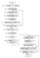
- An endoscope system includes an image acquisition unit that acquires an endoscope image obtained by photographing an observation object using an endoscope, and an endoscope image and an endoscope image using the endoscope image.
- Correction value calculation unit for calculating the correction value of the biological information calculated using or the correction value of the data used for calculation of the biological information and the use of the correction value
- An index value calculation unit that calculates one or more types of index values serving as a determination criterion for determining whether or not an index value is acceptable, a display unit that displays index values, an instruction for calculating a correction value, or a correction value
- An input unit that inputs an instruction to correct an endoscopic image, biological information, or data, and an instruction to calculate a correction value and the correction value calculation unit calculates the correction value, or performs correction When an instruction is obtained, the correction value is used to obtain an endoscopic image, biological information, Other includes a correcting unit for correcting the data.
- a determination unit that determines whether or not the correction value is calculated or the correction value can be used is provided using the index value, and the display unit displays the determination result of the determination unit in addition to the index value.
- the determination unit determines whether or not the correction value is calculated or the correction value can be used for each index value, and the display unit determines the determination result of the index value and the determination unit. Are preferably displayed.
- the display unit includes an improvement instruction unit that displays an improvement instruction regarding the imaging condition of the endoscope image when the determination unit determines that the calculation of the correction value or the use of the correction value is impossible.
- the improvement instruction unit makes an improvement determination for determining whether or not the shooting conditions have been improved, and displays the result of the improvement determination on the display unit.
- the image acquisition unit acquires a plurality of endoscope images obtained by photographing the observation target at different timings using the endoscope, and the correction value calculation unit calculates a correction value using the plurality of endoscope images.
- the index value calculation unit preferably calculates the index value using one or a plurality of endoscopic images.
- the image acquisition unit acquires a plurality of endoscope images obtained by changing the illumination light or the irradiation condition of the illumination light and photographing the observation target at different timings.
- the image acquisition unit acquires, as an endoscopic image, a correction value calculation image used for calculating a correction value and a biological information calculation image used for calculation of biological information.
- the correction value is calculated using the correction value calculation image in the endoscopic image
- the index value calculation unit may calculate the index value using the correction value calculation image in the endoscopic image. preferable.
- the image acquisition unit acquires a biometric information calculation image used for calculation of biometric information as an endoscopic image
- the correction value calculation unit calculates a correction value using the biometric information calculation image
- an index The value calculation unit preferably calculates the index value using the biological information calculation image used by the correction value calculation unit to calculate the correction value.
- the input unit is preferably an input screen displayed on the display unit or an operation unit.
- the index value calculation unit calculates the amount of movement of the observation target compared between the endoscopic images, the amount of movement of the observation target in one endoscopic image, the brightness, the pixel value, the presence / absence of the attached matter, or the attached amount.
- the index value is preferably calculated.
- the processor device of the present invention uses an endoscopic image and an endoscopic image by using an endoscopic image and an image acquisition unit that acquires an endoscopic image obtained by photographing an observation target using an endoscope. Whether to calculate a correction value or whether to use a correction value by using a correction value calculation unit that calculates a correction value of biometric information to be calculated or data used for calculation of biological information and an endoscopic image
- An index value calculation unit that calculates one or more types of index values that serve as a determination criterion for determining the display value, a display control unit that displays the index value on the display unit, an instruction to calculate a correction value, and a correction value calculation unit
- a correction unit that corrects an endoscopic image, biological information, or data using the correction value when a correction value is calculated or when an instruction to execute correction is obtained.
- the image acquisition unit acquires an endoscope image obtained by photographing an observation object using the endoscope
- the correction value calculation unit uses the endoscope image.
- the step of calculating the endoscope image, the biological information calculated using the endoscope image, or the correction value of the data used for calculating the biological information, and the index value calculation unit uses the endoscope image.
- a correction value calculation unit calculates a correction value by obtaining an instruction to calculate a value, or when an instruction to perform correction is obtained, the correction unit uses the correction value to obtain an endoscopic image or biological information. Or correcting the data.
- the endoscope system, the processor device, and the operation method of the endoscope system according to the present invention calculate an index value that is a determination criterion for determining whether or not a correction value can be calculated or whether or not a correction value can be used. Since it is displayed on the display unit, it is possible to assist in determining whether or not the photographing conditions are appropriate when obtaining the correction value calculation image.
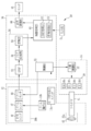
- the endoscope system 10 includes an endoscope 12 that captures an observation target, a light source device 14, a processor device 16, a monitor 18 that is a display unit, and a console 19.
- the endoscope 12 is optically connected to the light source device 14 and electrically connected to the processor device 16.
- the endoscope 12 includes an insertion portion 12a to be inserted into the subject, an operation portion 12b provided at the proximal end portion of the insertion portion 12a, a bending portion 12c provided at the distal end side of the insertion portion 12a, and a distal end portion. 12d.
- the bending portion 12c is bent by operating the angle knob 12e of the operation portion 12b.
- the distal end portion 12d is directed in a desired direction.
- the distal end portion 12d is provided with an ejection port (not shown) that ejects air, water, or the like toward the observation target.
- the operation unit 12b is provided with a mode switch 13a and a zoom operation unit 13b.
- the mode change switch 13a is used for an observation mode change operation.
- the endoscope system 10 has a normal observation mode and a special observation mode.
- the normal observation mode is an observation mode in which an observation image (hereinafter referred to as a normal observation image) having a natural color obtained by photographing an observation target using white light as illumination light is displayed on the monitor 18.
- the biological information of the observation target is calculated and displayed using an endoscope image obtained by photographing the observation target using the endoscope 12, or a specific tissue or structure of the observation target is emphasized. Generate and display an observation image.
- the special observation mode when calculating and displaying the biological information of the observation target is referred to as the biological information observation mode, and is special when generating and displaying an observation image highlighting a specific tissue or structure of the observation target.
- the observation mode is referred to as an enhanced observation mode. Note that these are examples, and the special observation mode can calculate and display biological information of an observation target, and can generate and display an observation image that emphasizes a specific tissue or structure of the observation target.
- the biological information is information relating to a living body that is not easily obtained at first glance from a normal observation image, and is, for example, numerical information relating to an observation target such as oxygen saturation or blood vessel density.
- “emphasis on a specific tissue or structure, etc.” includes not only emphasizing one or more types of specific tissue or structure among observable tissues or structures, but also one type. Emphasizing, etc., tissues or structures having some common characteristics from among the specific tissues or structures. That is, in the enhanced observation mode, a specific tissue such as a blood vessel is emphasized among observable tissues or structures. However, depending on the setting, not all blood vessels are emphasized. Only blood vessels at a specific depth from the reference point can be selectively emphasized. Further, for example, in the enhanced observation mode, only blood vessels whose thickness is within a specific range can be selectively enhanced.
- the special observation mode is an operation for calculating and displaying biological information using an endoscopic image, or displaying a specific tissue or structure with emphasis or the like (hereinafter referred to as a main operation).
- a correction operation is included.
- the correction operation is an operation for correcting “an endoscope image used in the main operation”, “biological information calculated in the main operation”, or “data used for calculating the biological information in the main operation”.
- Endoscope used for correcting the “endoscope image used in the main operation”, “biological information calculated in the main operation”, or “data used to calculate the biological information in the main operation” during the correction operation The image is a correction value calculation image.
- a plurality of endoscopic images obtained by photographing the observation target at different timings using the endoscope 12 are correction value calculation images.
- the “endoscopic image used in this operation” means an endoscope image (hereinafter referred to as a biological information calculation image) used for calculating biological information in this operation. Or it is an endoscopic image used for the production
- the “endoscopic image used in this operation” refers to an endoscopic image used for specifying a tissue or structure to be emphasized in this operation, or a specific tissue in this operation. Alternatively, it is an endoscopic image used for generating an observation image in which the structure is emphasized.
- Bio information calculated in this operation is biological information such as oxygen saturation calculated when the special observation mode is the biological information observation mode.
- data used for calculation of biological information in this operation is data used for calculation of biological information in addition to the endoscopic image. For example, when oxygen saturation is calculated as biological information, it is a data table or a conversion function for associating calculation values calculated using a plurality of endoscopic images with oxygen saturation.
- the correction of “endoscopic image used in the main operation”, “biological information calculated in the main operation”, or “data used for calculating the biological information in the main operation” calculates accurate biological information. This is a calibration of a special observation mode that is performed for the purpose of, for example, accurately emphasizing a specific tissue or structure.
- the endoscope system 10 performs an operation using an endoscopic image, and uses the prepared data associating the calculation result with the biological information for the purpose.
- Biometric information is calculated.
- This is the main operation in the biological information observation mode.
- a correction value is calculated using an endoscopic image.
- the “endoscopic image used in the main operation”, “biological information calculated in the main operation”, or “data used for calculating the biological information in the main operation” is corrected. .
- the biological information observation mode the biological information can be accurately calculated in this operation, and in the enhanced observation mode, an observation image that accurately emphasizes a specific tissue or structure is generated. And can be displayed.
- the special observation mode is a biological information observation mode for calculating and displaying the oxygen saturation. That is, the special observation mode of the present embodiment is an oxygen saturation observation mode.
- the oxygen saturation observation mode a calculation value having a correlation with the oxygen saturation is calculated using a plurality of endoscope images in this operation. Then, the oxygen saturation is calculated using the calculated calculated value and data that associates the calculated value with the oxygen saturation. Thereafter, an observation image (hereinafter, referred to as an oxygen saturation image 110 (see FIG. 9)) showing a value of oxygen saturation using a pseudo color using a plurality of endoscopic images and the calculated oxygen saturation. Generate and display.
- the oxygen saturation observation mode of the present embodiment uses a plurality of endoscope images (correction value calculation images) obtained by photographing an observation object at different timings using the endoscope 12 in the correction operation. To calculate a correction value. Then, using the calculated correction value, the data used for calculating the oxygen saturation at the time of the main operation (that is, the “data that associates the calculated value with the oxygen saturation”) is corrected.
- the processor device 16 is electrically connected to the monitor 18 and the console 19.
- the monitor 18 outputs and displays an observation image in each observation mode, image information attached to the observation image, and the like.
- the console 19 is one of input units 74 (see FIG. 2 or 3) that functions as a user interface that receives input operations such as function settings.
- the processor device 16 may be connected to an external recording unit (not shown) for recording images, image information, and the like.
- the light source device 14 includes a light source unit 20 that emits illumination light and a light source control unit 22 that controls driving of the light source unit 20.
- the light source unit 20 includes four light sources: a BS light source 20a, a BL light source 20b, a G light source 20c, and an R light source 20d.
- the BS light source 20a, the BL light source 20b, the G light source 20c, and the R light source 20d are all LEDs (Light-Emitting-Diode).
- the light source unit 20 can use a combination of a laser diode (LD), a phosphor, and a band limiting filter, or a combination of a lamp such as a xenon lamp and a band limiting filter.
- LD laser diode
- a phosphor a phosphor
- a band limiting filter or a combination of a lamp such as a xenon lamp and a band limiting filter.
- the BS light source 20a is a blue light source that emits the first blue light BS having a center wavelength of about 450 ⁇ 10 nm and a wavelength band of about 420 nm to 500 nm.
- the BL light source 20b is a blue light source that emits blue so-called narrow band light (hereinafter referred to as second blue light BL) having a center wavelength and a wavelength band of about 470 nm ⁇ 10 nm.
- the G light source 20c is a green light source that emits green light G having a center wavelength of about 540 ⁇ 20 nm and a wavelength band of about 480 nm to 600 nm.
- the R light source 20d is a red light source that emits red light R having a center wavelength of about 640 ⁇ 20 nm and a wavelength band of about 600 nm to 650 nm.
- the light source control unit 22 independently controls the lighting and extinguishing timings of each of the light sources 20a to 20d constituting the light source unit 20, the light emission amount at the time of lighting, and the like. Under the control of the light source control unit 22, the light source unit 20 emits normal observation illumination light used in the normal observation mode and special observation illumination light used in the special observation mode.
- the light source controller 22 turns on the BS light source 20a, the G light source 20c, and the R light source 20d at the same time.
- the normal observation illumination light is white light including the first blue light BS, the green light G, and the red light R.
- white light includes pseudo white light that can be regarded as white light.
- the light source unit 20 in the normal observation mode, the light source unit 20 always lights up the white light. However, the light source 20 may emit white light in accordance with the photographing frame.
- the special observation illumination light includes main operation illumination light used in the main operation and correction operation illumination light used in the correction operation.
- the illumination light for the main operation and the illumination light for the correction operation are respectively light of one or a plurality of colors (a plurality of types of light having different wavelengths, wavelength bands, or spectral spectra) depending on the practical mode of the special observation mode. Including. Further, the illumination light for the main operation and the illumination light for the correction operation may be different from each other or may be equal to each other depending on a practical aspect of the special observation mode.
- the light source control unit 22 alternately turns on and off the light sources 20a to 20d in the first pattern and the second pattern in this operation.
- the first pattern is a light emission pattern for lighting the BL light source 20b alone.
- the second blue light BL becomes the special observation illumination light.
- the second pattern is a pattern in which the BS light source 20a, the G light source 20c, and the R light source 20d are turned on simultaneously.
- white light including the first blue light BS, the green light G, and the red light R becomes the special observation illumination light. Accordingly, in the oxygen saturation observation mode, the second blue light BL and the white light are alternately emitted in accordance with the photographing frame in this operation.
- the light source control unit 22 alternately turns on and off the first pattern and the second pattern in accordance with the photographing frame even in the correction operation. Therefore, in the oxygen saturation observation mode that is the special observation mode of the present embodiment, the illumination light for main operation and the illumination light for correction operation are the same, and the light emission pattern is also the same. Thus, even in the correction operation, the correction illumination light equal to the main operation illumination light is emitted, the oxygen saturation is calculated in the correction operation, and the oxygen saturation calculated in the correction operation is used as a correction value. This is because the data used for calculating the oxygen saturation is corrected in this operation.
- the illumination light emitted from the light source unit 20 enters the light guide 41.
- the light guide 41 is built in the endoscope 12 and the universal cord, and propagates the illumination light to the distal end portion 12d of the endoscope 12.
- the universal cord is a cord that connects the endoscope 12 to the light source device 14 and the processor device 16.
- a multimode fiber can be used as the light guide 41.
- a thin fiber cable having a core diameter of 105 ⁇ m, a cladding diameter of 125 ⁇ m, and a diameter of 0.3 to 0.5 mm including a protective layer serving as an outer skin can be used.
- the distal end portion 12d of the endoscope 12 is provided with an illumination optical system 30a and a photographing optical system 30b.
- the illumination optical system 30 a has an illumination lens 45, and illumination light is irradiated to the observation target through the illumination lens 45.
- the photographing optical system 30b includes an objective lens 46, a zoom lens 47, and an image sensor 48.
- the image sensor 48 reflects reflected light or the like of illumination light returning from the observation target via the objective lens 46 and the zoom lens 47 (in addition to the reflected light, scattered light, fluorescence emitted from the observation target, or medicine administered to the observation target)
- the observation object is photographed using the image including the fluorescence caused by
- the zoom lens 47 moves by operating the zoom operation unit 13b, and enlarges or reduces the observation target to be photographed using the image sensor 48.
- the image sensor 48 is a primary color sensor, a B pixel (blue pixel) having a blue color filter, a G pixel (green pixel) having a green color filter, and an R pixel (red pixel) having a red color filter. These three types of pixels are provided.
- the blue color filter mainly transmits light in the blue band, specifically, light in the wavelength band of 380 to 560 nm.
- the transmittance of the blue color filter has a peak near the wavelength of 460 to 470 nm.
- the green color filter mainly transmits light in the green band, specifically, light in the wavelength band of 460 to 470 nm.
- the red color filter mainly transmits light in the red band, specifically, light in the wavelength band of 580 to 760 nm.
- the illumination light for normal observation to be used is white light and includes blue, green, and red components, so that a B image, a G image, and an R image can be obtained for each photographing frame. .
- the special observation illumination light in the special observation mode of the present embodiment is switched between the second blue light BL and the white light composed of the first blue light BS, the green light G, and the red light R for each photographing frame. .
- the B image is substantially obtained in the photographing frame in which the special observation illumination light is the second blue light BL.
- a B image, a G image, and an R image are obtained in an imaging frame in which the special observation illumination light is white light.
- the B image acquired in the imaging frame in which the special observation illumination light is the second blue light BL is referred to as a B1 image
- the R images are referred to as a B2 image, a G2 image, and an R2 image, respectively.
- B1 image, B2 image, G2 image, and R2 image are endoscopic images obtained by photographing the observation target at different timings using the endoscope 12, and are referred to as multi-frame images in relation to the mutual photographing timing.
- each of the B1 image, the B2 image, the G2 image, and the R2 image is a multiframe image.
- it is two or more endoscopic images obtained by combining a B1 image and one or more images of a B2 image, a G2 image, or an R2 image.
- a CCD (Charge-Coupled Device) sensor or a CMOS (Complementary Metal-Oxide Semiconductor) sensor can be used as the image sensor 48 .
- the image sensor 48 of the present embodiment is a primary color sensor, but a complementary color sensor can also be used.
- Complementary color sensors include, for example, a cyan pixel with a cyan color filter, a magenta pixel with a magenta color filter, a yellow pixel with a yellow color filter, and a green pixel with a green color filter.
- a complementary color sensor is used, an image obtained from each color pixel can be converted into a B image, a G image, and an R image by performing complementary color-primary color conversion.
- a monochrome sensor not provided with a color filter can be used as the image sensor 48 instead of the color sensor. In this case, the image of each color can be obtained by sequentially photographing the observation target using illumination light of each color such as BGR.
- the processor device 16 includes a control unit 52, an image acquisition unit 54, an image processing unit 61, and a display control unit 66.
- the processor device 16 has a central processing unit (CPU), and this CPU functions as the control unit 52, the image acquisition unit 54, the image processing unit 61, and the display control unit 66.
- CPU central processing unit
- the control unit 52 receives the mode switching signal from the mode switching switch 13a and inputs the control signal to the light source control unit 22 and the image sensor 48 to switch the observation mode. In addition, the control unit 52 also performs overall control of the endoscope system 10 such as synchronous control of illumination light irradiation timing and imaging timing.
- the image acquisition unit 54 acquires an image to be observed from the image sensor 48.
- the image acquisition unit 54 acquires a set of a B image, a G image, and an R image for each shooting frame.
- the image acquisition unit 54 acquires an image corresponding to the special observation illumination light in each shooting frame for each shooting frame.
- the image acquisition unit 54 acquires a plurality of endoscope images obtained by photographing the observation target at different timings while changing the illumination light or the irradiation condition of the illumination light.
- the image acquisition unit 54 alternately acquires at least a B1 image and a set of a B2 image, a G2 image, and an R2 image for each photographing frame. .
- the image acquisition unit 54 includes a DSP (Digital Signal Processor) 56, a noise reduction unit 58, and a conversion unit 59, and performs various processes on the acquired image using these.
- DSP Digital Signal Processor
- the DSP 56 performs various processing such as defect correction processing, offset processing, gain correction processing, linear matrix processing, gamma conversion processing, demosaic processing, and YC conversion processing on the acquired image as necessary.
- the defect correction process is a process for correcting the pixel value of the pixel corresponding to the defective pixel of the image sensor 48.
- the offset process is a process for reducing the dark current component from the image subjected to the defect correction process and setting an accurate zero level.
- the gain correction process is a process for adjusting the signal level of each image by multiplying the image subjected to the offset process by a gain.
- the linear matrix process is a process for improving the color reproducibility of the image subjected to the offset process, and the gamma conversion process is a process for adjusting the brightness and saturation of the image after the linear matrix process.
- the demosaic process (also referred to as an isotropic process or a synchronization process) is a process of interpolating the pixel values of the missing pixels, and is applied to the image after the gamma conversion process.
- the missing pixel is a pixel having no pixel value because pixels of other colors are arranged in the image sensor 48 due to the arrangement of the color filters.
- the B image is an image obtained by photographing the observation target in the B pixel, the pixel at the position corresponding to the G pixel or the R pixel of the image sensor 48 has no pixel value.
- the B image is interpolated to generate pixel values of the pixels at the positions of the G pixel and the R pixel of the image sensor 48.
- the YC conversion process is a process for converting the demosaiced image into a luminance channel Y, a color difference channel Cb, and a color difference channel Cr.
- the noise reduction unit 58 performs noise reduction processing on the luminance channel Y, the color difference channel Cb, and the color difference channel Cr using, for example, a moving average method or a median filter method.
- the conversion unit 59 reconverts the luminance channel Y, the color difference channel Cb, and the color difference channel Cr after the noise reduction processing into an image of each color of BGR again.
- the image processing unit 61 includes a normal processing unit 62 and a special processing unit 63.
- the normal processing unit 62 operates in the normal observation mode, and performs color conversion processing, color enhancement processing, and structure enhancement processing on the B image, G image, and R image for one shooting frame subjected to the above-described various processing.
- the normal observation image is generated.
- a 3 ⁇ 3 matrix process, a gradation conversion process, a three-dimensional LUT (look-up table) process, and the like are performed on an image of each color of BGR.
- the color enhancement process is a process for enhancing the color of an image
- the structure enhancement process is a process for enhancing a tissue or structure to be observed such as a blood vessel or a pit pattern.
- the display control unit 66 sequentially acquires the normal observation images from the normal processing unit 62, converts the acquired normal observation images into a format suitable for display, and sequentially outputs and displays them on the monitor 18. Thereby, in the normal observation mode, a doctor or the like can observe the observation target using the moving image of the normal observation image.
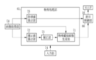
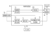
- the special processing unit 63 includes a special observation image generation unit 71, a correction value calculation unit 72, a correction unit 73, and an index value calculation unit 75 as shown in FIG.
- the special observation image generation unit 71 uses the endoscopic image acquired from the image acquisition unit 54 to generate an observation image (hereinafter referred to as a special observation image) according to the actual mode of the special observation mode.
- the special observation image generation unit 71 calculates biological information using an endoscopic image and also displays a special observation image representing biological information (hereinafter referred to as a biological information image). Is generated.
- the special observation mode is the enhanced observation mode
- the special observation image generation unit 71 uses the endoscopic image to extract a specific tissue or structure from other tissues or structures that are not selected or otherwise enhanced (selected or otherwise enhanced). And a special observation image (hereinafter referred to as an enhanced observation image) in which a specific tissue or structure extracted is emphasized.
- the special observation image generation unit 71 generates a natural observation image instead of the special observation image by using the endoscopic image in the correction operation.
- the natural observation image referred to here is an observation image in which a specific tissue or structure is not emphasized and is not colored for displaying biological information. That is, the special observation image generation unit 71 generates an observation image 101 (hereinafter referred to as “normal observation image”, see FIG. 8) similar to the normal observation image in the normal observation mode in the correction operation.
- the special observation image generation unit 71 displays the generated special observation image or normal observation image 101 on the monitor 18 via the display control unit 66. That is, the monitor 18 displays a special observation image in this operation, and displays the normal observation image 101 in the correction operation.
- the display control unit 66 also displays information related to the special observation image or the normal observation image 101, information for assisting the judgment of a doctor, buttons for operation input, and the like on the monitor 18 as necessary. For example, when the oxygen saturation image 110 is displayed on the monitor 18, the display control unit 66 displays an indicator (information related to the oxygen saturation image 110) indicating the correspondence between the pseudo color and the oxygen saturation. It is displayed on the monitor 18.
- the information that supports the judgment of a doctor or the like is, for example, the index value 102 (see FIG. 8) calculated by the index value calculation unit 75.
- the correction value calculation unit 72 uses the endoscopic image acquired from the image acquisition unit 54 as a correction value calculation image, so that “an endoscopic image used in the main operation”, “biological information calculated in the main operation”, Alternatively, a correction value used for correcting “data used for calculating biological information in this operation” is calculated.
- the correction value calculation unit 72 selects which of the “endoscope image used in the main operation”, “biological information calculated in the main operation”, or “data used to calculate the biometric information in the main operation”. Whether to calculate a correction value to be used for correction depends on the actual mode of the special observation mode.
- the correction unit 73 uses the correction value calculated by the correction value calculation unit 72 to use the “endoscopic image used in the main operation”, “biological information calculated in the main operation”, or “biological information in the main operation”. "Data used for calculation” is corrected. Naturally, when the correction value calculation unit 72 calculates a correction value for “an endoscopic image used in this operation”, the correction unit 73 uses the correction value calculated by the correction value calculation unit 72. The “endoscopic image used in this operation” is corrected. The same applies to “biological information calculated in this operation” or “data used to calculate biometric information in this operation”.
- At least one of the calculation of the correction value by the correction value calculation unit 72 and the use of the correction value by the correction unit 73 is performed after an instruction from the input unit 74 is input.
- the input unit 74 uses an instruction to calculate a correction value (hereinafter referred to as a correction value calculation instruction) or a correction value according to the setting, or “an endoscope image used in the main operation” or “calculation in the main operation”.
- An instruction to execute correction of “biological information to be performed” or “data used for calculation of biological information in this operation” (hereinafter referred to as a correction execution instruction) is input to the special processing unit 63. Therefore, the correction unit 73 performs correction using the correction value when the correction value calculation instruction is obtained and the correction value calculation unit 72 calculates the correction value, or when the correction unit 73 receives the correction execution instruction. is there.
- the correction value calculation unit 72 When the input unit 74 is set to input a correction value calculation instruction, the correction value calculation unit 72 does not calculate a correction value until a correction value calculation instruction is input from the input unit 74. For this reason, the correction unit 73 does not execute correction until the correction value calculation unit 72 calculates the correction value. On the other hand, when a correction value calculation instruction is input from the input unit 74 to the special processing unit 63, the correction value calculation unit 72 calculates a correction value. Then, the correction unit 73 automatically performs correction using the correction value calculated by the correction value calculation unit 72.
- the correction unit 73 When the input unit 74 is set to input a correction execution instruction, the correction unit 73 does not perform correction until a correction execution instruction is input from the input unit 74. When a correction execution instruction is input from the input unit 74, the correction unit 73 performs correction.
- the correction value calculation unit 72 can appropriately calculate a correction value even before the correction execution instruction is input from the input unit 74. In this case, the correction execution instruction is also an instruction for permitting use of the already calculated correction value.
- the correction value calculation unit 72 may calculate a correction value when a correction execution instruction is input from the input unit 74.
- the input unit 74 is an input screen (graphical user interface (GUI)) displayed on the monitor 18 or an operation unit included in the endoscope system 10.
- the “operation unit” included in the endoscope system 10 includes an operation unit 12 b that forms part of the endoscope 12, and a separate foot switch (not shown) or the endoscope 12 such as the console 19. Including operating devices.
- the “operation unit” included in the endoscope system 10 includes not only an operation device connected to the endoscope 12 but also an operation device connected to the processor device 16 or the light source device 14. That is, the “operation unit” included in the endoscope system 10 includes all operation devices that can directly or indirectly input a correction value calculation instruction or a correction execution instruction to the special processing unit 63.
- the input unit 74 is a GUI, and inputs a correction value calculation instruction to the correction value calculation unit 72.
- the index value calculation unit 75 calculates one or more types of index values 102 using the endoscopic image acquired from the image acquisition unit 54.
- the index value 102 is a numerical value that serves as a determination criterion for determining whether correction values can be calculated or whether correction values can be used. However, the index value 102 is substantially the same whether the correction value is calculated or not, and whether or not the correction value is used.
- the index value 102 is a determination criterion for determining whether or not the correction value can be calculated.
- the index value 102 is set. Is a criterion for determining whether or not the correction value can be used.
- the index value calculation unit 75 compares the amount of motion of the observation target compared between endoscopic images (hereinafter referred to as inter-image motion amount) and the amount of motion of the observation target in one endoscopic image (
- the index value 102 is calculated for any one or more of the amount of motion in the image), the brightness of the observation target or the endoscopic image, the pixel value of the endoscopic image, the presence or absence of the adhering matter, and the adhering amount. .
- the amount of motion between images is, for example, the direction of movement, rotation, or deformation of an observation target when comparing endoscope images acquired at different timings using the endoscope 12, such as B1 images and B2 images.
- the direction and size of movement and the like are calculated for corresponding points between a plurality of endoscopic images.
- a statistic such as an average value, a median value, or a maximum value can be used as the amount of movement.
- the amount of movement between images relates to the magnitude of the movement of the observation target (relative movement of the observation target due to the movement of the endoscope 12) due to the change in the shooting position and the change in the shooting angle. Information is also automatically included.
- the amount of motion in the image is a numerical value that represents the degree of blurring of the endoscopic image caused by movement, rotation, or deformation of the observation target when the endoscopic image is taken.
- the endoscopic image is subjected to frequency analysis. It is a numerical value obtained by
- the movement amount in the image includes the change in the shooting position when the endoscope image is shot, and the movement of the observation target due to the change in the shooting angle (the relative observation target caused by the movement of the endoscope 12). Information on the magnitude of movement) is automatically included.
- the brightness of the observation target or the endoscopic image is, for example, the luminance or brightness of the entire observation target or the endoscopic image or a specific portion (for example, the central portion).
- the index value calculation unit 75 calculates, for example, a statistic such as an average value or a median value of brightness or brightness of pixels in the entire endoscopic image or a specific portion as the index value 102 related to brightness.
- the pixel value of the endoscopic image is, for example, a statistical value such as a pixel value of a specific pixel or an average value, median value, maximum value, or minimum value of pixel values in a specific part or the whole of the endoscopic image. Amount.
- the index value calculation unit 75 calculates the appearance frequency of pixel values, the distribution of pixel values, or a statistic (standard deviation or the like) relating to the distribution of pixel values, etc. in a specific part or the whole of the endoscopic image. It can be calculated as an index value 102 related to the pixel value.
- the adhering substance is, for example, a residue, mucus, or a sprayed drug (including spraying, application, injection, or administration without using the endoscope 12).
- the amount of deposits refers to the number, area, color, or density (coloring density caused by deposits) of the places where deposits are present.
- the index value calculation unit 75 calculates the index value 102 at least in the correction operation.
- the display control unit 66 acquires the index value 102 from the index value calculation unit 75
- the display control unit 66 displays the index value 102 on the monitor 18 side by side or superimposed on the observation image (the normal observation image 101 or the special observation image). Therefore, the doctor or the like can know the index value 102 calculated by the index value calculation unit 75 in real time along with the observation image. If the index value 102 is viewed, it is possible to appropriately correct whether or not the situation is suitable for calculating the correction value (that is, whether or not the correction value can be calculated), or using the correction value calculated by the correction value calculation unit 72. Whether or not the correction value can be used can be easily determined.
- the input unit 74 is used. Then, the correction value calculation instruction or the correction execution instruction is input to the special processing unit 63 to calculate the correction value or execute the correction.
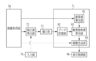
- the special observation image generation unit 71 includes a calculation value calculation unit 81, a data storage unit 82, an oxygen saturation calculation unit 83, and An image generation unit 84 is provided.
- the calculation value calculation unit 81 acquires a plurality of endoscope images from the image acquisition unit 54, and uses the plurality of endoscope images to calculate calculation values used by the oxygen saturation calculation unit 83 to calculate the oxygen saturation. calculate. Specifically, the calculation value calculation unit 81 acquires a B1 image, a B2 image, a G2 image, and an R2 image. Then, the ratio B1 / G2 of the B1 image to the G2 image and the ratio R2 / G2 of the R2 image to the G2 image are calculated for each pixel. The ratio B1 / G2 and the ratio R2 / G2 are calculation values used for calculating the oxygen saturation.
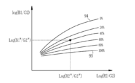
- the data storage unit 82 stores data used when the oxygen saturation calculation unit 83 calculates the oxygen saturation using the calculation value calculated by the calculation value calculation unit 81. That is, the data storage unit 82 stores the correlation between the calculated value and the oxygen saturation in a format such as LUT. As shown in FIG. 5, when this correlation is expressed in a feature space formed by using the vertical axis Log (B1 / G2) and the horizontal axis Log (R2 / G2), points having the same oxygen saturation are connected. Isolines are formed generally along the lateral direction. Further, the isoline is positioned downward in the vertical axis direction as the oxygen saturation is increased. For example, the isoline 93 with an oxygen saturation of 100% is located below the isoline 94 with an oxygen saturation of 0%.
- the above correlation is closely related to the light absorption characteristics of oxygenated hemoglobin (graph 96) and reduced hemoglobin (graph 97) shown in FIG.
- the wavelength of the second blue light BL (about 470 ⁇ 10 nm) has a large difference in extinction coefficient between oxyhemoglobin and deoxyhemoglobin, so that the amount of light absorption changes due to the oxygen saturation of hemoglobin.
- the second blue light BL is easy to handle oxygen saturation information. Therefore, the oxygen saturation can be calculated by using the ratio B1 / G2 obtained by standardizing the B1 image by using the G2 image for correction of illuminance unevenness and the like.
- the ratio B1 / G2 depends not only on the oxygen saturation but also on the blood volume.
- the ratio R2 / G2 which changes mainly depending on the blood volume, is used, so that the oxygen saturation can be calculated without being influenced by the blood volume.
- the wavelength of the green light G (about 540 ⁇ 20 nm) included in the G2 image is a wavelength at which the extinction coefficient is likely to change due to the blood volume because the extinction coefficient of hemoglobin is relatively high.
- the data storage unit 82 stores the correlation between the ratio B1 / G2 and the ratio R2 / G2 and the oxygen saturation, but the data storage unit 82 may store other correlations. it can.
- the oxygen saturation using a calculated value (hereinafter referred to as another calculated value) obtained as a result of performing another calculation (for example, difference processing) different from the above based on the B1 image, the B2 image, the G2 image, and the R2 image.
- the data storage unit 82 can store a correlation that associates the other calculated values with the oxygen saturation.
- the oxygen saturation calculation unit 83 calculates the oxygen saturation using the correlation, which is the data stored in the data storage unit 82, and the calculated value calculated by the calculated value calculation unit 81. Specifically, the oxygen saturation calculation unit 83 refers to the correlation stored in the data storage unit 82 and calculates the oxygen saturation corresponding to the ratio B1 / G2 and the ratio R2 / G2 for each pixel. For example, the oxygen saturation corresponding to the ratio B1 / G2 and the ratio R2 / G2 of a certain pixel is “40%” with reference to the correlation stored in the data storage unit 82. Therefore, the oxygen saturation calculation unit 83 calculates the oxygen saturation in this pixel as “40%” (see FIG. 5). When the correlation stored in the data storage unit 82 is corrected by the correction unit 73, the oxygen saturation calculation unit 83 calculates the oxygen saturation with reference to the corrected correlation.
- the ratio B1 / G2 and the ratio R2 / G2 are hardly increased or extremely decreased. That is, the combinations of the values of the ratio B1 / G2 and the ratio R2 / G2 are distributed below the upper limit isoline 93 (see FIG. 5) of the oxygen saturation 100%, or conversely, the oxygen saturation 0 It is rarely distributed more in the information than the isoline 94 (see FIG. 5) at the lower limit of%. If the combination of the values of the ratio B1 / G2 and the ratio R2 / G2 is distributed below the upper limit isoline 93, the oxygen saturation calculation unit 83 sets the oxygen saturation of the pixel to the upper limit. Calculated as “100%”.
- the oxygen saturation calculation unit 83 calculates the oxygen saturation of the pixel. Calculate as “0%”. Further, when the points corresponding to the ratio B1 / G2 and the ratio R2 / G2 are not distributed between the upper limit isoline 93 and the lower limit isoline 94, the reliability of oxygen saturation in the pixel is low. May be displayed, or oxygen saturation may not be calculated.
- the image generation unit 84 generates the oxygen saturation image 110 using the plurality of endoscope images acquired from the image acquisition unit 54 and the oxygen saturation calculated by the oxygen saturation calculation unit 83. To do. More specifically, the image generation unit 84 acquires the B2 image, the G2 image, and the R2 image, and applies a gain corresponding to the oxygen saturation to these endoscopic images for each pixel. For example, the image generation unit 84 multiplies pixels having an oxygen saturation of 60% or more by the same gain “1” for all of the B2 image, the G2 image, and the R2 image.
- a pixel having an oxygen saturation of less than 60% is multiplied by a gain less than “1” for the B2 image, and a gain of “1” or more is multiplied for the G2 image and the R2 image.
- the image generation unit 84 generates a color observation image using the B2, G2, and R2 images that have been gained as described above.
- the observation image generated using the B2, G2, and R2 images gained for each pixel according to the oxygen saturation is the oxygen saturation image 110.
- the image generation unit 84 sequentially displays the generated oxygen saturation image 110 on the monitor 18 via the display control unit 66.
- a region of high oxygen in this embodiment, a region where the oxygen saturation is 60% or more and 100% or less
- the low oxygen region where the oxygen saturation is lower than the specific value in this embodiment, the region where the oxygen saturation is 0% or more and less than 60%
- the image generation unit 84 multiplies the gain for pseudo-coloring only the low oxygen region, but the oxygen saturation is also increased in the high oxygen region. A corresponding gain may be applied, and the entire oxygen saturation image 110 may be pseudo-colored.
- the low oxygen region and the high oxygen region are separated with an oxygen saturation of 60% as a boundary, but the value of the oxygen saturation at this boundary is also arbitrary.
- the oxygen saturation image 110 is generated as described above, whereas in the correction operation, the image generation unit 84 generates the normal observation image 101.
- the image generation unit 84 acquires the B2 image, the G2 image, and the R2 image from the image acquisition unit 54, and generates a color observation image using these endoscopic images.
- the observation image generated using the B2 image, the G2 image, and the R2 image acquired from the image acquisition unit 54 as they are is the normal observation image 101 in the oxygen saturation observation mode. That is, the normal observation image 101 generated by the image generation unit 84 represents the observation target with a natural color in substantially the same manner as the normal observation image generated by the normal processing unit 62 in the normal observation mode.
- the image generation unit 84 sequentially displays the normal observation image 101 generated in the correction operation on the monitor 18 via the display control unit 66.
- the input unit 74 is a GUI and inputs a correction value calculation instruction to the correction value calculation unit 72.
- the correcting unit 73 corrects the correlation (data used for calculating the oxygen saturation) stored in the data storage unit 82. For this reason, the correction value calculation unit 72 calculates a correction value for correcting the correlation between the calculated value and the oxygen saturation.
- the correction value calculation unit 72 acquires the B1 image, the B2 image, the G2 image, and the R2 image from the image acquisition unit 54. Then, using the plurality of endoscope images, a ratio B1 / G2 of the B1 image to the G2 image and a ratio R2 / G2 of the R2 image to the G2 image are calculated for each pixel. That is, the correction value calculation unit 72 calculates the same calculation value as the calculation value calculation unit 81. Thereafter, using the calculated value and the correlation before correction (hereinafter referred to as default correlation) stored in advance in the data storage unit 82, the oxygen saturation is calculated for each pixel in the same manner as the oxygen saturation calculation unit 83. Calculate to obtain the representative value.
- the representative value is an average value in the present embodiment, but other statistics such as a median value and a mode value can be used as the representative value.
- the representative value is substantially constant. For example, if an appropriate part having no apparent lesion is photographed for the correction operation and the photographing condition is appropriate, the representative value of the oxygen saturation is a specific value (for example, approximately depending on the observation site, for example, 70%). In addition, the shape and mutual relationship of the isolines in the feature space are substantially constant regardless of individual differences of observation objects. Therefore, if the representative value of the oxygen saturation calculated by the correction value calculation unit 72 is compared with this specific value, how much the default correlation is shifted within the feature space, the oxygen saturation of the observation target can be accurately determined. It can be calculated whether it will be able to calculate to.
- the default correlation shift amount and shift direction are correction amounts calculated by the correction value calculation unit 72.
- the correction unit 73 corrects the default correlation according to the shift amount and the shift direction calculated by the correction value calculation unit 72.
- the oxygen saturation calculation unit 83 calculates the oxygen saturation using the corrected correlation.
- the special processing unit 63 starts a correction operation (S11).
- the image acquisition unit 54 sequentially acquires a plurality of endoscopic images (S12).
- the special observation image generation unit 71 generates the normal observation image 101 in the image generation unit 84 (S13).
- the index value calculation unit 75 calculates the index value 102 using a plurality of endoscopic images acquired from the image acquisition unit 54 (S14).
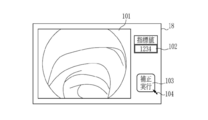
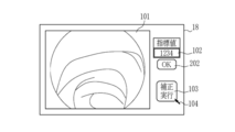
- the display control unit 66 acquires the normal observation image 101 from the image generation unit 84, acquires the index value 102 from the index value calculation unit 75, and displays these on the monitor 18 (S15). For example, as illustrated in FIG. 8, the display control unit 66 displays the index value 102 on the monitor 18 in the normal observation image 101.
- the display control unit 66 also displays on the monitor 18 a correction execution button 103 that is a GUI for inputting a correction execution instruction.
- the correction execution button 103 is the input unit 74.
- the doctor or the like looks at the normal observation image 101 and the index value 102 to determine whether or not the situation is appropriate for the correction. Then, it is determined whether or not an appropriate location without an obvious lesion is imaged and the imaging conditions are appropriate (S16). A doctor or the like can determine whether or not an appropriate location without an apparent lesion is captured by looking at the normal observation image 101. Further, a doctor or the like can determine whether or not the imaging condition is appropriate for correction by looking at the normal observation image 101, but the monitor 18 displays an index value 102 that supports this determination. Or the like can be more reliably determined based on the index value 102 as to whether or not the photographing condition is appropriate.
- the doctor or the like When viewing the normal observation image 101 and the index value 102 and determining that the situation is not appropriate for correction, the doctor or the like does not press the correction execution button 103. For this reason, the endoscope system 10 repeatedly performs step S12 to step S15 (S16: NO), and sequentially updates the normal observation image 101 and the index value 102. In this case, the doctor or the like adjusts the imaging position or the like so that the situation suitable for correction is obtained while observing the normal observation image 101 and the index value 102 being updated.
- the doctor or the like operates the pointer 104 (see FIG. 8) using the console 19.
- the correction execution button 103 functioning as the input unit 74 is pressed to input a correction value calculation instruction to the correction value calculation unit 72 (S17).
- the correction value calculation unit 72 calculates a correction value using a plurality of endoscopic images acquired from the image acquisition unit 54 (S18).
- the correction unit 73 performs correction of the correlation stored in the data storage unit 82 using the correction value calculated by the correction value calculation unit 72 (S19).
- the control unit 52 ends the correction operation in the oxygen saturation observation mode and proceeds to the main operation (S20).
- the special observation image generation unit 71 acquires a plurality of endoscope images again from the image acquisition unit 54 (S21), and the calculation value calculation unit 81 uses these plurality of endoscope images.
- An operation value is calculated (S22).
- the oxygen saturation calculation unit 83 calculates the oxygen saturation for each pixel using the calculated value and the corrected correlation corrected by the correction unit 73 from the data storage unit 82 (S23).
- the image generation unit 84 uses the oxygen saturation calculated by the oxygen saturation calculation unit 83 and a plurality of endoscopic images to generate an oxygen saturation image 110. (See FIG. 9) is generated, and as shown in FIG.
- the oxygen saturation image 110 is displayed on the monitor 18 via the display control unit 66 (S24).
- the display control unit 66 displays the indicator 111 indicating the relationship between the color of the oxygen saturation image 110 and the oxygen saturation side by side on the oxygen saturation image 110.
- the imaging condition calculates the correction value in the correction operation. It is possible to easily determine whether it is appropriate for the acquisition of the image for use and the execution of correction. In particular, even if it is difficult for a doctor or the like to determine from the normal observation image 101 alone whether or not the imaging condition is appropriate for acquisition and correction execution of the correction value calculation image, it can be easily determined by looking at the index value 102. . Therefore, according to the endoscope system 10, it is less likely to cause a problem that correction value calculation and correction of correlation and the like have failed as a result, as compared with the conventional endoscope system.
- the oxygen saturation image 110 displayed on the monitor 18 in this operation is based on the fact that the oxygen saturation calculation unit 83 calculates the oxygen saturation using the corrected correlation, and thus the individual difference of the observation target, etc. Regardless of the exact value.
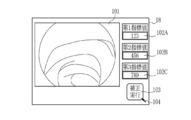
- the index value calculation unit 75 calculates one index value 102 and displays it on the monitor 18 (see FIG. 8), but the first index value 102A and the second index value shown in FIG. Like the index value 102 ⁇ / b> B and the third index value 102 ⁇ / b> C, the index value calculation unit 75 preferably calculates a plurality of types of index values 102 and displays them on the monitor 18. This is because it can be determined from a plurality of viewpoints whether the imaging conditions are appropriate for obtaining the correction value calculation image and executing correction, and as a result, the oxygen saturation can be calculated more reliably.
- the first index value 102A, the second index value 102B, and the third index value 102C are the inter-image motion amount, the intra-image motion amount, the brightness of the observation target or the endoscopic image, and the pixel value of the endoscopic image. Or the presence or absence or amount of deposits.
- three values of the first index value 102A, the second index value 102B, and the third index value 102C are calculated and displayed, but the index value 102 is related to all of these or any two of them. May be calculated and displayed.
- the correction unit 73 corrects the correlation, which is “data used for calculation of oxygen saturation in the main operation”, but the correction unit 73 determines that “the endoscopic image used in the main operation”. "Or” biological information calculated in this operation "can be corrected.
- the correction unit 73 corrects the “endoscopic image used in the main operation”, as shown in FIG. 11, the correction unit 73 uses the endoscope image used by the calculation value calculation unit 81 in the main operation as an image acquisition unit. 54. Then, the corrected endoscopic image is input to the calculation value calculation unit 81. By doing this, it becomes possible to calculate an accurate oxygen saturation as in the first embodiment.
- the correction value calculation unit 72 in this case, for example, the B1 image, the G2 image, and the like so that the representative value of the oxygen saturation becomes a specific value (for example, 70%) when referring to the default correlation.
- the gain to be applied to one or more of the R2 images is calculated, and this gain is input to the correction unit 73 as a correction value.
- the correction unit 73 corrects “biological information calculated in this operation”
- the correction unit 73 acquires the oxygen saturation calculated by the oxygen saturation calculation unit 83 as shown in FIG.
- the corrected oxygen saturation is input to the image generation unit 84.
- the oxygen saturation image 110 showing the correct oxygen saturation can be generated and displayed as in the first embodiment.
- the correction value calculation unit 72 in this case calculates, for example, the difference between the representative value of the oxygen saturation and a specific value (for example, 70%) as the correction value, as in the first embodiment.
- the correction unit 73 can correct the oxygen saturation calculated by the oxygen saturation calculation unit 83 to an accurate value of oxygen saturation by adding, subtracting, multiplying, and dividing the correction value.
- the index value 102 is displayed on the monitor 18, but the index value 102 is “OK (possible)” or “NG (impossible) for calculating the correction value or using the correction value. It is preferable to clearly indicate which is indicated. In this way, the meaning can be easily grasped without considering the meaning represented by the numerical value of the index value 102. Therefore, it is possible to more efficiently support the determination as to whether or not the shooting conditions are appropriate for correction.
- the special processing unit 63 is provided with a determination unit 201.
- the determination unit 201 acquires the index value 102 from the index value calculation unit 75 and determines whether or not the correction value can be calculated or the correction value can be used (whether or not correction can be performed). Specifically, the determination unit 201 compares the index value 102 with a threshold value that is predetermined according to the type of the index value 102. For example, when the index value 102 is within the range determined by the threshold value, the determination unit 201 determines that the index value 102 is “OK” for calculating the correction value or using the correction value. On the other hand, when the index value 102 is outside the range determined by the threshold, the determination unit 201 determines “NG” for the calculation of the correction value or the use of the correction value.
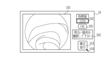
- the determination unit 201 inputs the determination result 202 (see FIG. 14) of “OK” or “NG” to the display control unit 66. Therefore, as shown in FIG. 14, the display control unit 66 displays the determination result 202 (“OK” in FIG. 14) in addition to the index value 102. A doctor or the like can determine whether or not the situation is appropriate for the correction by looking at the index value 102, but the determination result 202 makes it possible to determine more reliably and easily.
- the determination result 202 of the determination unit 201 Since the determination result 202 of the determination unit 201 has the same significance as the index value 102 in terms of a determination criterion as to whether or not the situation is appropriate for correction, the determination result 202 is a kind of index value 102 having a different display form. . For this reason, in FIG. 14, both the index value 102 and the determination result 202 are displayed on the monitor 18, but only the determination result 202 may be displayed as the index value 102 in the first embodiment. In this specification, as shown in FIG. 14, when the index value 102 is displayed except when the index value 102 and the determination result 202 are displayed in parallel, such as when the distinction is necessary, only the index value 102 is displayed. , The case where only the determination result 202 is displayed, and the case where both the index value 102 and the determination result 202 are displayed are included.
- the determination unit 201 determines whether or not correction values can be calculated or the correction values can be used for each index value 102. Then, the determination result 202 for each index value 102 is displayed on the monitor 18. For example, as shown in FIG. 15, when the three index values 102 of the first index value 102A, the second index value 102B, and the third index value 102C are calculated and displayed, the first index value 102A The determination result 202A, the determination result 202B for the second index value 102B, and the determination result 202C for the third index value 102C are displayed on the monitor 18, respectively.
- the threshold value used for determination may be different for each index value 102.
- the determination result 202 is displayed as an “OK” or “NG” message.
- an indicator, a character, a figure, an icon, a display lamp, or the like on the monitor 18 simulating a display lamp
- the determination result 202 may be displayed by turning on or off.
- the determination result 202 can be indicated by an indicator light that lights in red and when the determination result 202 is “OK”.
- the determination result 202 is displayed by an indicator, it is preferable to provide a threshold value used for determination by the determination unit 201 in a stepwise manner and to display which step it belongs to.
- the determination result 202 when the determination result 202 is displayed with an indicator, the determination result 202 in a plurality of stages, such as impossible, acceptable, good, and special, is displayed in a particularly easy-to-understand manner using colors, gauge lengths, and the like. can do.
- the index value 102 and the determination result 202 are displayed on the monitor 18, but when the determination result 202 is “NG”, the type of the index value 102 with the determination result 202 being “NG” is displayed. Accordingly, it is preferable to further display an improvement instruction 302 (see FIG. 17) regarding the imaging conditions of the endoscopic image. This is because, if there is the improvement instruction 302, the shooting conditions can be adjusted more appropriately and efficiently, and a situation suitable for correction can be promptly achieved.
- the special processing unit 63 is provided with an improvement instruction unit 301 in addition to the determination unit 201.
- the improvement instruction unit 301 acquires the index value 102 and the determination result 202 from the determination unit 201. Then, when the determination result 202 is “NG”, the improvement instruction unit 301 is based on the relationship between the type of the index value 102 for which the determination result 202 is “NG” and the threshold value used by the determination unit 201.
- An improvement instruction 302 is displayed on the monitor 18.
- the improvement instruction 302 is an instruction regarding the imaging condition of the endoscopic image, and is, for example, a message indicating a guideline for setting the determination result 202 that was “NG” to “OK”.
- the threshold value used by the index value 102 and the determination unit 201 is “NG”
- the improvement instruction unit 301 displays an improvement instruction 302 “Please photograph a bright part” on the monitor 18.
- the improvement instruction unit 301 displays an improvement instruction 302 “Please shoot a dark part” on the monitor 18.
- the threshold value used by the index value 102 and the determination unit 201 is “NG”
- the improvement instruction unit 301 displays an improvement instruction 302 “Please shoot at a place with less movement” on the monitor 18. indicate.
- the improvement instruction unit 301 reads “Wash the observation target. ”Is displayed on the monitor 18 for prompting the removal of the adhering matter.
- the improvement instructing unit 301 sets the “shooting distance apart”. Please display an improvement instruction 302 for prompting adjustment of the shooting distance on the monitor 18.
- an improvement instruction 302 is displayed for each index value 102 and determination result 202.
- the improvement instruction unit 301 After displaying the improvement instruction 302 on the monitor 18, the improvement instruction unit 301 further performs an improvement determination to determine whether or not the imaging condition related to the index value 102 whose determination result 202 is “NG” has been improved, and this improvement
- the determination result is preferably displayed on the monitor 18.
- the improvement determination result 303 is displayed as a message or the like as shown in FIG.
- the improvement determination is performed by acquiring, for example, an endoscopic image or the index value 102 and the determination result 202.
- the endoscope system 10 has a plurality of different in the main operation and the correction operation.
- the endoscope image can be acquired, and the main operation and the correction operation can be respectively performed.
- the endoscope images acquired by the image acquisition unit 54 in the correction operation and the main operation are the same, the correction value calculation image, and the living body. It is an image for information calculation. Therefore, in the correction operation, the correction value calculation unit 72 calculates a correction value using the biometric information calculation image, and the index value calculation unit 75 is used by the correction value calculation unit 72 to calculate the correction value. It can be said that the index value 102 is calculated using the biological information calculation image.
- the endoscope system 10 uses the correction operation illumination light and the main operation illumination light to change the color (wavelength, wavelength band, or spectral spectrum) of light used for each photographing frame.
- the number of endoscopic images to be acquired and the like can be arbitrarily changed.
- the image acquisition unit 54 acquires a correction value calculation image and a biological information calculation image as an endoscopic image.
- the correction value calculation unit 72 calculates a correction value using the correction value calculation image among these endoscopic images
- the index value calculation unit 75 includes, among these endoscopic images, The index value can be calculated using the correction value calculation image.
- the light source unit 20 includes a plurality of light sources 20a to 20d, and the light emitted from these light sources is superimposed to form illumination light.
- an endoscope system 670 shown in FIG. 19 includes a broadband light source 676, a rotary filter 677, and a filter control unit instead of the light sources 20a to 20d and the light source control unit 22 of the first embodiment. 678.
- the image sensor 48 is a monochrome sensor not provided with a color filter. The rest is the same as the endoscope system 10 of the first to third embodiments.
- the broadband light source 676 is a xenon lamp, a white LED or the like, and emits white light whose wavelength band ranges from blue to red.
- the rotary filter 677 is rotatably arranged in the optical path of the broadband light source 676, limits the band of white light emitted by the broadband light source 676, and makes some components enter the light guide 41 as illumination light. For this reason, the rotary filter 677 is appropriately divided, and for example, an optical filter that transmits the first blue light BS, a filter that transmits the second blue light BL, a filter that transmits the green light G, and the red light R are divided into each section. A transparent filter is provided.
- the filter control unit 678 controls the position and rotation of the rotary filter 677 in accordance with the observation mode and the shooting frame.
- the B1, B2, G, and R images are displayed in the special observation mode
- the B, G, and R images are displayed in the normal observation mode.
- the present invention is implemented in an endoscope system that performs observation by inserting the endoscope 12 provided with the image sensor 48 into a subject.
- the present invention is also suitable for a mirror system.
- a capsule endoscope system includes at least a capsule endoscope 700 and a processor device (not shown).
- the capsule endoscope 700 includes a light source unit 702, a control unit 703, an image sensor 704, an image processing unit 706, and a transmission / reception antenna 708.
- the light source unit 702 corresponds to the light source unit 20.
- the control unit 703 functions in the same manner as the light source control unit 22 and the control unit 52.
- the control unit 703 can communicate with the processor device of the capsule endoscope system using the transmission / reception antenna 708 wirelessly.
- the processor device of the capsule endoscope system is substantially the same as the processor device 16 of the first to third embodiments, but the image processing unit 706 corresponding to the image acquisition unit 54 and the image processing unit 61 is a capsule endoscope.
- An observation image such as an oxygen saturation image that is provided in 700 is transmitted to the processor device via the transmission / reception antenna 708.
- the image sensor 704 is configured similarly to the image sensor 48.
- the correction operation is performed when the observation mode is switched from the normal observation mode to the special observation mode.
- the correction operation is optional in addition to the timing at which the observation mode is switched to the special observation mode. It can be implemented at the timing.
- the correction operation can be forcibly performed by an operation input from the console 19 or the like. This function is useful when it is desired to redo correction at an arbitrary timing.
- the image acquisition unit 54 acquires a plurality of endoscope images obtained by photographing the observation target at different timings, and the correction value calculation unit 72 uses the plurality of endoscope images.
- the index value calculation unit 75 calculates the index value 102 using a plurality of endoscopic images.
- the special observation modes of the first to third embodiments are oxygenated. This is because the saturation observation mode.
- the image acquisition unit 54 corrects according to the actual mode of the special observation mode. In operation, one endoscopic image can be acquired, and the correction value calculation unit 72 can calculate a correction value using the one endoscopic image.
- the image acquisition unit 54 acquires a plurality of endoscope images obtained by photographing the observation target at different timings
- the correction value calculation unit 72 includes a plurality of endoscopes. Even when the correction value is calculated using the image, the index value calculation unit 75 calculates the index value 102 using one of the plurality of endoscopic images acquired by the image acquisition unit 54. Can be calculated.
Abstract
補正値算出用画像を得る際に、撮影の条件が適切であるか否かの判断を支援する内視鏡システム、プロセッサ装置、及び、内視鏡システムの作動方法を提供する。内視鏡システムは、生体情報の算出に使用するデータ等の補正値を算出する補正値算出部と、補正値の算出の可否、または、補正値の使用の可否を判断する判断基準となる指標値を1種類または複数種類算出する指標値算出部と、指標値を表示する表示部と、補正値を算出する指示、または、補正値を用いて補正を実行する指示を入力する入力部と、補正値を算出する指示を得て補正値算出部が補正値を算出した場合、または、補正を実行する指示を得た場合に、補正値を用いて補正する補正部と、を備える。
Description
本発明は、内視鏡を用いて観察対象を撮影して得る内視鏡画像を用いて演算する内視鏡システム、プロセッサ装置、及び、内視鏡システムの作動方法に関する。
医療分野においては、光源装置、内視鏡、及びプロセッサ装置を備える内視鏡システムを用いて診断することが一般的になっている。特に、内視鏡を用いて観察対象を撮影して内視鏡画像を得るだけでなく、内視鏡画像を用いて血管等の組織や腺管構造等の構造を強調した表示用の画像(以下、観察画像という)を生成及び表示する内視鏡システムが普及している。また、近年においては、内視鏡画像を用いて生体情報を得る内視鏡システムもある。例えば、血中ヘモグロビンの酸素飽和度(生体情報)を用いた病変部の診断が行われつつある。例えば、酸化ヘモグロビンと還元ヘモグロビンの吸光係数が異なる波長帯域の光等を観察対象に照射して複数の内視鏡画像を取得し、これら複数の内視鏡画像を用いて所定の演算をして酸素飽和度を算出する方法がある(特許文献1及び特許文献2)。
酸素飽和度等の生体情報は、食道、胃、もしくは大腸等の部位の違い、または、患者の性別若しくは年齢といった患者の個体差に起因して異なる場合がある。このため、特許文献1の内視鏡システムにおいては、実際に観察する患者及び部位を撮影した内視鏡画像を用いて、酸素飽和度の算出に使用するデータを補正(キャリブレーション)しておくことによって、観察する部位の違いや患者の個体差等に依らずに、正確な酸素飽和度を算出できるようにしている。また、特許文献2の内視鏡システムにおいては、現在と過去の酸素飽和度を比較して、算出した酸素飽和度を補正し、正確な酸素飽和度を求めるようにしている。
酸素飽和度等の生体情報の算出に使用するデータ等を補正するためには、当然ながら、どの程度補正すればよいかを表す補正値を求める必要がある。例えば生体情報として酸素飽和度を算出する場合、特許文献2の内視鏡システムのように、患者及び部位に関して過去の酸素飽和度等のデータを蓄積している場合を除けば、特許文献1の内視鏡システムのように、通常はリアルタイムに患者を撮影して得た内視鏡画像を用いて補正値を求めなければならない。
また、補正値が不正確な場合、この不正確な補正値を用いて補正したデータ等を使用して生体情報を算出すれば、当然に、算出した生体情報も不正確になる。このため、補正値の算出に使用する内視鏡画像(以下、補正値算出用画像という)は、補正値の算出誤差が許容範囲に収まる適切な条件において観察対象を撮影した画像でなければならない。
しかしながら、補正値算出用画像を得る際に、撮影の条件が適切であるか否かをリアルタイムに判断するのは容易ではない。例えば、観察対象に動きがある状況で観察対象を撮影して得た内視鏡画像を補正値算出用画像として用いると、補正値の算出誤差が大きくなってしまうので、動きがない状況で観察対象を撮影して得た内視鏡画像を補正値算出用画像として用いることが好ましい。しかし、生体である観察対象の動きを停止することはできないので、補正値算出用画像を得る際の撮影条件としてどの程度の動きまでが補正値の算出の際に許容できるのかをリアルタイムに判断する必要がある。これは補正値の算出方法等に精通していなければできない判断であるから、内視鏡システムの使用者である医師等にとっては通常は困難な判断である。照明光の光量等の他の撮影の条件についても同様である。
本発明は、補正値算出用画像を得る際に、撮影の条件が適切であるか否かの判断を支援する内視鏡システム、プロセッサ装置、及び、内視鏡システムの作動方法を提供することを目的とする。
本発明の内視鏡システムは、内視鏡を用いて観察対象を撮影した内視鏡画像を取得する画像取得部と、内視鏡画像を用いて、内視鏡画像、内視鏡画像を用いて算出する生体情報、または、生体情報の算出に使用するデータの補正値を算出する補正値算出部と、内視鏡画像を用いて、補正値の算出の可否、または、補正値の使用の可否を判断する判断基準となる指標値を1種類または複数種類算出する指標値算出部と、指標値を表示する表示部と、補正値を算出する指示、または、補正値を用いて、内視鏡画像、生体情報、もしくは、データの補正を実行する指示を入力する入力部と、補正値を算出する指示を得て補正値算出部が補正値を算出した場合、または、補正を実行する指示を得た場合に、補正値を用いて、内視鏡画像、生体情報、または、データを補正する補正部と、を備える。
指標値を用いて、補正値の算出または補正値の使用の可否を判定する判定部を備え、表示部は、指標値に加え、判定部の判定結果を表示することが好ましい。
指標値算出部が複数種類の指標値を算出する場合、判定部は、指標値ごとに補正値の算出または補正値の使用の可否を判定し、表示部は、指標値と判定部の判定結果とをそれぞれ表示することが好ましい。
判定部が補正値の算出または補正値の使用を不可と判定した場合に、表示部に内視鏡画像の撮影条件に関する改善指示を表示する改善指示部を備える好ましい。
改善指示部は、改善指示の表示後に、撮影条件が改善したか否かを判定する改善判定をし、かつ、改善判定の結果を表示部に表示することが好ましい。
画像取得部は、内視鏡を用いて各々異なるタイミングにおいて観察対象を撮影した複数の内視鏡画像を取得し、補正値算出部は、複数の内視鏡画像を用いて補正値を算出し、指標値算出部は、1または複数の内視鏡画像を用いて指標値を算出することが好ましい。
画像取得部は、照明光または照明光の照射条件を変え、かつ、異なるタイミングにおいて観察対象を撮影した複数の内視鏡画像を取得することが好ましい。
画像取得部は、内視鏡画像として、補正値の算出に使用する補正値算出用画像と、生体情報の算出に使用する生体情報算出用画像と、を取得し、補正値算出部は、内視鏡画像のうち、補正値算出用画像を用いて補正値を算出し、かつ、指標値算出部は、内視鏡画像のうち、補正値算出用画像を用いて指標値を算出することが好ましい。
画像取得部は、内視鏡画像として、生体情報の算出に使用する生体情報算出用画像を取得し、補正値算出部は、生体情報算出用画像を用いて補正値を算出し、かつ、指標値算出部は、補正値算出部が補正値の算出に使用する生体情報算出用画像を用いて指標値を算出することが好ましい。
入力部は、表示部に表示する入力画面、または、操作部であることが好ましい。
指標値算出部は、内視鏡画像間で比較した観察対象の動き量、1つの内視鏡画像内における観察対象の動き量、明るさ、画素値、または、付着物の有無もしくは付着量について、指標値を算出することが好ましい。
本発明のプロセッサ装置は、内視鏡を用いて観察対象を撮影した内視鏡画像を取得する画像取得部と、内視鏡画像を用いて、内視鏡画像、内視鏡画像を用いて算出する生体情報、または、生体情報の算出に使用するデータの補正値を算出する補正値算出部と、内視鏡画像を用いて、補正値の算出の可否、または、補正値の使用の可否を判断する判断基準となる指標値を1種類または複数種類算出する指標値算出部と、表示部に指標値を表示する表示制御部と、補正値を算出する指示を得て補正値算出部が補正値を算出した場合、または、補正を実行する指示を得た場合に、補正値を用いて、内視鏡画像、生体情報、または、データを補正する補正部と、を備える。
本発明の内視鏡システムの作動方法は、画像取得部が、内視鏡を用いて観察対象を撮影した内視鏡画像を取得するステップと、補正値算出部が、内視鏡画像を用いて、内視鏡画像、内視鏡画像を用いて算出する生体情報、または、生体情報の算出に使用するデータの補正値を算出するステップと、指標値算出部が、内視鏡画像を用いて、補正値の算出の可否、または、補正値の使用の可否を判断する判断基準となる指標値を1種類または複数種類算出するステップと、表示部が、指標値を表示するステップと、補正値を算出する指示を得て補正値算出部が補正値を算出した場合、または、補正を実行する指示を得た場合に、補正部が、補正値を用いて、内視鏡画像、生体情報、または、データを補正するステップと、を備える。
本発明の内視鏡システム、プロセッサ装置、及び、内視鏡システムの作動方法は、補正値の算出の可否、または、補正値の使用の可否を判断する判断基準となる指標値を算出して表示部に表示するので、補正値算出用画像を得る際に、撮影の条件が適切であるか否かの判断を支援することができる。
[第1実施形態]
図1に示すように、内視鏡システム10は、観察対象を撮影する内視鏡12と、光源装置14と、プロセッサ装置16と、表示部であるモニタ18と、コンソール19とを有する。内視鏡12は、光源装置14と光学的に接続するとともに、プロセッサ装置16に電気的に接続する。内視鏡12は、被検体内に挿入する挿入部12aと、挿入部12aの基端部分に設けられた操作部12bと、挿入部12aの先端側に設けられた湾曲部12cと、先端部12dとを有している。操作部12bのアングルノブ12eを操作することにより、湾曲部12cが湾曲する。この湾曲部12cが湾曲した結果、先端部12dが所望の方向に向く。なお、先端部12dには、観察対象に向けて空気や水等を噴射する噴射口(図示しない)が設けられている。
図1に示すように、内視鏡システム10は、観察対象を撮影する内視鏡12と、光源装置14と、プロセッサ装置16と、表示部であるモニタ18と、コンソール19とを有する。内視鏡12は、光源装置14と光学的に接続するとともに、プロセッサ装置16に電気的に接続する。内視鏡12は、被検体内に挿入する挿入部12aと、挿入部12aの基端部分に設けられた操作部12bと、挿入部12aの先端側に設けられた湾曲部12cと、先端部12dとを有している。操作部12bのアングルノブ12eを操作することにより、湾曲部12cが湾曲する。この湾曲部12cが湾曲した結果、先端部12dが所望の方向に向く。なお、先端部12dには、観察対象に向けて空気や水等を噴射する噴射口(図示しない)が設けられている。
また、操作部12bには、アングルノブ12eの他、モード切り替えスイッチ13a、ズーム操作部13bが設けられている。モード切り替えスイッチ13aは、観察モードの切り替え操作に用いる。内視鏡システム10は、通常観察モードと特殊観察モードを有する。通常観察モードは、照明光に白色光を用いて観察対象を撮影して得る自然な色合いの観察画像(以下、通常観察画像という)をモニタ18に表示する観察モードである。
特殊観察モードは、内視鏡12を用いて観察対象を撮影した内視鏡画像を用いて、観察対象の生体情報を算出及び表示し、または、観察対象の特定の組織もしくは構造を強調等した観察画像を生成及び表示する。以下においては、観察対象の生体情報を算出及び表示する場合の特殊観察モードを、生体情報観察モードといい、観察対象の特定の組織もしくは構造を強調等した観察画像を生成及び表示する場合の特殊観察モードを、強調観察モードという。なお、これらは例であり、特殊観察モードは、観察対象の生体情報を算出及び表示し、かつ、観察対象の特定の組織もしくは構造を強調等した観察画像を生成及び表示することができる。
生体情報とは、通常観察画像からは一見して知得することが容易でない生体に関する情報であり、例えば、酸素飽和度または血管の密度等の観察対象に関する数値的な情報である。また、強調観察モードにおける「特定の組織もしくは構造の強調等」には、観察可能な組織または構造の中から、1または複数種類の特定の組織または構造を強調等することのみならず、1種類の特定の組織または構造の中から、一部の共通の特性を有する組織または構造を強調等することを含む。すなわち、強調観察モードにおいては、観察可能な組織または構造のうち、例えば血管という特定の組織を強調等するが、設定によっては、全ての血管を強調等するのではなく、例えば粘膜表面等の所定の基準点からの特定の深さにある血管のみを選択的に強調等することができる。また、例えば、強調観察モードにおいては、太さが特定の範囲内にある血管のみを選択的に強調等することができる。
また、特殊観察モードは、上記のように、内視鏡画像を用いて、生体情報を算出及び表示し、または、特定の組織もしくは構造を強調等して表示する動作(以下、本動作という)の他に、補正動作を含む。補正動作は、「本動作において使用する内視鏡画像」、「本動作において算出する生体情報」、または、「本動作において生体情報の算出に使用するデータ」の補正をする動作である。
補正動作時に、上記「本動作において使用する内視鏡画像」、「本動作において算出する生体情報」、または、「本動作において生体情報の算出に使用するデータ」の補正に使用する内視鏡画像が補正値算出用画像である。本実施形態においては、補正動作時に、内視鏡12を用いて各々異なるタイミングにおいて観察対象を撮影して得る複数の内視鏡画像が補正値算出用画像である。
具体的には、生体情報観察モードの場合、「本動作において使用する内視鏡画像」とは、本動作において生体情報の算出に用いる内視鏡画像(以下、生体情報算出用画像という)、または、本動作において算出した生体情報を表示する観察画像の生成に用いる内視鏡画像である。また、強調観察モードの場合には、「本動作において使用する内視鏡画像」とは、本動作において強調等する組織もしくは構造の特定に用いる内視鏡画像、または、本動作において特定の組織もしくは構造を強調等した観察画像の生成に用いる内視鏡画像である。
「本動作において算出する生体情報」とは、特殊観察モードが生体情報観察モードの場合に算出する酸素飽和度等の生体情報である。また、「本動作において生体情報の算出に使用するデータ」とは、内視鏡画像の他に、生体情報の算出に使用するデータである。例えば、生体情報として酸素飽和度を算出する場合、複数の内視鏡画像を用いて算出する演算値を、酸素飽和度に対応付けるためのデータテーブルまたは変換関数等である。
なお、「本動作において使用する内視鏡画像」、「本動作において算出する生体情報」、または、「本動作において生体情報の算出に使用するデータ」の補正は、正確な生体情報を算出するための、または、正確に特定の組織や構造を強調等するために行う特殊観察モードの校正(キャリブレーション)である。
特殊観察モードの一例である生体情報観察モードにおいては、内視鏡システム10は、内視鏡画像を用いて演算し、その演算結果を生体情報に対応付ける予め用意したデータを用いて、目的とする生体情報を算出する。これが、生体情報観察モードの本動作である。一方、補正動作においては、内視鏡画像を用いて補正値を算出する。そして、算出した補正値を用いて、「本動作において使用する内視鏡画像」、「本動作において算出する生体情報」、または、「本動作において生体情報の算出に使用するデータ」を補正する。これにより、生体情報観察モードの場合には、本動作において、生体情報を正確に算出することができ、強調観察モードの場合には、特定の組織もしくは構造を正確に強調等した観察画像を生成及び表示することができる。
以下、本実施形態においては、特殊観察モードは酸素飽和度を算出及び表示する生体情報観察モードである。すなわち、本実施形態の特殊観察モードは、酸素飽和度観察モードである。酸素飽和度観察モードは、本動作において、複数の内視鏡画像を用いて、酸素飽和度と相関がある演算値を算出する。そして、算出した演算値と、演算値を酸素飽和度に対応付けるデータとを用いて酸素飽和度を算出する。その後、複数の内視鏡画像と、算出した酸素飽和度とを用いて、酸素飽和度の値を疑似カラーを用いて示す観察画像(以下、酸素飽和度画像110(図9参照)という)を生成及び表示する。また、本実施形態の酸素飽和度観察モードは、補正動作において、内視鏡12を用いて各々異なるタイミングにおいて観察対象を撮影して得る複数の内視鏡画像(補正値算出用画像)を用いて補正値を算出する。そして、算出した補正値を用いて、本動作時に酸素飽和度の算出に使用するデータ(すなわち、上記「演算値を酸素飽和度に対応付けるデータ」)を補正する。
プロセッサ装置16は、モニタ18及びコンソール19と電気的に接続する。モニタ18は、各観察モードの観察画像や観察画像に付帯する画像情報等を出力表示する。コンソール19は、機能設定等の入力操作を受け付けるユーザインタフェースとして機能する入力部74(図2または図3参照)の1つである。なお、プロセッサ装置16には、画像や画像情報等を記録する外付けの記録部(図示省略)を接続してもよい。
図2に示すように、光源装置14は、照明光を発光する光源部20と、光源部20の駆動を制御する光源制御部22と、を備えている。
光源部20は、BS光源20a、BL光源20b、G光源20c、及び、R光源20dの4個の光源を備える。本実施形態においては、BS光源20a、BL光源20b、G光源20c、及び、R光源20dはいずれもLED(Light Emitting Diode)である。光源部20には、これらのLEDの代わりに、LD(Laser Diode)と蛍光体と帯域制限フィルタとの組み合わせや、キセノンランプ等のランプと帯域制限フィルタの組み合わせ等を用いることができる。
BS光源20aは、中心波長が約450±10nm、波長帯域が約420nm~500nmの第1青色光BSを発光する青色光源である。BL光源20bは、中心波長及び波長帯域が約470nm±10nmであり、青色のいわゆる狭帯域光(以下、第2青色光BLという)を発光する青色光源である。G光源20cは、中心波長が約540±20nm、波長帯域が約480nm~600nmに及ぶ緑色光Gを発光する緑色光源である。R光源20dは、中心波長が約640±20nm、波長帯域が約600nm~650nmに及ぶ赤色光Rを発光する赤色光源である。
光源制御部22は、光源部20を構成する各光源20a~20dの点灯や消灯のタイミング、及び点灯時の発光量等をそれぞれ独立に制御する。この光源制御部22の制御により、光源部20は、通常観察モードにおいて使用する通常観察用照明光と、特殊観察モードにおいて使用する特殊観察用照明光と、を発光する。
通常観察モードの場合、光源制御部22は、BS光源20a、G光源20c、及びR光源20dを同時に点灯する。このため、通常観察用照明光は、第1青色光BSと、緑色光Gと、赤色光Rとを含む白色光である。本明細書においては、白色光には、白色光とみなすことができる擬似白色光を含む。また、本実施形態においては、通常観察モードの場合、光源部20は上記白色光を常時点灯するが、撮影フレームに合わせて、白色光を発光しても良い。
特殊観察用照明光は、本動作において用いる本動作用照明光と、補正動作において用いる補正動作用照明光と、を含む。本動作用照明光及び補正動作用照明光は、特殊観察モードの実際的態様に応じて、それぞれ、1または複数の色の光(波長、波長帯域、または分光スペクトルが異なる複数種類の光)を含む。また、本動作用照明光と補正動作用照明光とは、特殊観察モードの実際的態様によっては、互いに異なる場合があり、また、互いに等しい場合がある。
本実施形態の特殊観察モードである酸素飽和度観察モードにおいては、光源制御部22は本動作において第1パターンと第2パターンで各光源20a~20dの点灯及び消灯を交互に繰り返す。第1パターンは、BL光源20bを単独で点灯する発光パターンである。このため、第1パターンの際には、第2青色光BLが特殊観察用照明光になる。一方、第2パターンは、BS光源20aと、G光源20cと、R光源20dを同時に点灯するパターンである。このため、第2パターンの際には、第1青色光BSと、緑色光Gと、赤色光Rとを含む白色光が特殊観察用照明光になる。したがって、酸素飽和度観察モードは、本動作において、第2青色光BLと白色光を撮影フレームに合わせて交互に発光する。
また、光源制御部22は、補正動作においても上記第1パターンと第2パターンの点灯及び消灯を撮影フレームに合わせて交互に繰り返す。したがって、本実施形態の特殊観察モードである酸素飽和度観察モードにおいては、本動作用照明光と補正動作用照明光は等しく、発光のパターンも同じである。このように、補正動作においても、本動作用照明光と等しい補正用照明光を発光するのは、補正動作においても酸素飽和度を算出し、補正動作において算出した酸素飽和度を補正値として、本動作において酸素飽和度の算出に用いるデータの補正をするからである。
光源部20が発光した照明光は、ライトガイド41に入射する。ライトガイド41は、内視鏡12及びユニバーサルコード内に内蔵されており、照明光を内視鏡12の先端部12dまで伝搬する。ユニバーサルコードは、内視鏡12と光源装置14及びプロセッサ装置16とを接続するコードである。なお、ライトガイド41としては、マルチモードファイバを使用できる。一例として、コア径105μm、クラッド径125μm、外皮となる保護層を含めた径がφ0.3~0.5mmの細径なファイバケーブルを使用できる。
内視鏡12の先端部12dには、照明光学系30aと撮影光学系30bが設けられている。照明光学系30aは、照明レンズ45を有しており、この照明レンズ45を介して照明光が観察対象に照射される。撮影光学系30bは、対物レンズ46、ズームレンズ47、及びイメージセンサ48を有している。イメージセンサ48は、対物レンズ46及びズームレンズ47を介して、観察対象から戻る照明光の反射光等(反射光の他、散乱光、観察対象が発する蛍光、または、観察対象に投与等した薬剤に起因した蛍光等を含む)を用いて観察対象を撮影する。なお、ズームレンズ47は、ズーム操作部13bの操作をすることで移動し、イメージセンサ48を用いて撮影する観察対象を拡大または縮小する。
イメージセンサ48は、原色系のカラーセンサであり、青色カラーフィルタを有するB画素(青色画素)、緑色カラーフィルタを有するG画素(緑色画素)、及び、赤色カラーフィルタを有するR画素(赤色画素)の3種類の画素を備える。青色カラーフィルタは、主として青色帯域の光、具体的には波長帯域が380~560nmの波長帯域の光を透過する。青色カラーフィルタの透過率は、波長460~470nm付近においてピークになる。緑色カラーフィルタは、主として緑色帯域の光、具体的には、460~470nmの波長帯域の光を透過する。赤色カラーフィルタは、主として赤色帯域の光、具体的には、580~760nmの波長帯域の光を透過する。
イメージセンサ48を用いて観察対象を撮影すると、最大で、B画素において撮影して得るB画像(青色画像)、G画素において撮像して得るG画像(緑色画像)、及び、R画素において撮影して得るR画像(赤色画像)の3種類の内視鏡画像を同時に得ることができる。通常観察モードの場合、使用する通常観察用照明光は白色光であり、青色、緑色、及び赤色の成分を含むので、撮影フレーム毎に、B画像、G画像、及びR画像を得ることができる。
一方、本実施形態の特殊観察モードにおける特殊観察用照明光は、撮影フレーム毎に、第2青色光BLと、第1青色光BS、緑色光G、及び赤色光Rからなる白色光とで切り替わる。このため、特殊観察用照明光が第2青色光BLである撮影フレームにおいては実質的にB画像のみが得られる。また、特殊観察用照明光が白色光である撮影フレームにおいてはB画像、G画像、及びR画像が得られる。以下、特殊観察用照明光が第2青色光BLである撮影フレームで取得するB画像をB1画像といい、特殊観察用照明光が白色光である撮影フレームにおいて取得するB画像、G画像、及びR画像を、それぞれB2画像、G2画像、及びR2画像という。
B1画像と、B2画像、G2画像、及びR2画像は、内視鏡12を用いて各々異なるタイミングにおいて観察対象を撮影した内視鏡画像であり、相互の撮影タイミングの関係においてマルチフレーム画像という場合がある。例えば、本実施形態の酸素飽和度観察モードにおいては、B1画像、B2画像、G2画像、及びR2画像はそれぞれがマルチフレーム画像である。また、複数のマルチフレーム画像という場合には、例えば、B1画像と、B2画像、G2画像、またはR2画像のうちのいずれか1以上の画像とを組み合わせた2以上の内視鏡画像である。
なお、イメージセンサ48としては、CCD(Charge Coupled Device)センサや、CMOS(Complementary Metal Oxide Semiconductor)センサを利用可能である。また、本実施形態のイメージセンサ48は、原色系のカラーセンサであるが、補色系のカラーセンサを用いることもできる。補色系のカラーセンサは、例えば、シアンカラーフィルタが設けられたシアン画素、マゼンタカラーフィルタが設けられたマゼンタ画素、イエローカラーフィルタが設けられたイエロー画素、及び、グリーンカラーフィルタが設けられたグリーン画素を有する。補色系カラーセンサを用いる場合に上記各色の画素から得る画像は、補色-原色色変換をすれば、B画像、G画像、及びR画像に変換できる。また、カラーセンサの代わりに、カラーフィルタを設けていないモノクロセンサをイメージセンサ48として使用できる。この場合、BGR等各色の照明光を用いて観察対象を順次撮影することにより、上記各色の画像を得ることができる。
プロセッサ装置16は、制御部52と、画像取得部54と、画像処理部61と、表示制御部66と、を有する。例えば、プロセッサ装置16はCPU(Central processing unit)を有し、このCPUが制御部52、画像取得部54、画像処理部61、及び表示制御部66として機能する。
制御部52は、モード切り替えスイッチ13aからモード切り替え信号の入力を受けて、光源制御部22及びイメージセンサ48に制御信号を入力することにより、観察モードを切り替える。この他、制御部52は、照明光の照射タイミングと撮影のタイミングの同期制御等の内視鏡システム10の統括的制御も行う。
画像取得部54は、イメージセンサ48から観察対象の画像を取得する。通常観察モードの場合、画像取得部54は、撮影フレーム毎に、B画像、G画像、及びR画像の組を取得する。また、特殊観察モードの場合、画像取得部54は、撮影フレーム毎に、各撮影フレームにおける特殊観察用照明光に応じた画像を取得する。例えば、特殊観察モードの場合、画像取得部54は、照明光または照明光の照射条件を変え、かつ、異なるタイミングにおいて観察対象を撮影した複数の内視鏡画像を取得する。本実施形態の特殊観察モードである酸素飽和度観察モードの場合、画像取得部54は、少なくとも、B1画像と、B2画像、G2画像、及びR2画像の組とを撮影フレーム毎に交互に取得する。
画像取得部54は、DSP(Digital Signal Processor)56と、ノイズ低減部58と、変換部59と、を有し、これらを用いて、取得した画像に各種処理を施す。
DSP56は、取得した画像に対し、必要に応じて欠陥補正処理、オフセット処理、ゲイン補正処理、リニアマトリクス処理、ガンマ変換処理、デモザイク処理、及びYC変換処理等の各種処理を施す。
欠陥補正処理は、イメージセンサ48の欠陥画素に対応する画素の画素値を補正する処理である。オフセット処理は、欠陥補正処理を施した画像から暗電流成分を低減し、正確な零レベルを設定する処理である。ゲイン補正処理は、オフセット処理をした画像にゲインを乗じることにより各画像の信号レベルを整える処理である。リニアマトリクス処理は、オフセット処理をした画像の色再現性を高める処理であり、ガンマ変換処理は、リニアマトリクス処理後の画像の明るさや彩度を整える処理である。デモザイク処理(等方化処理や同時化処理とも言う)は、欠落した画素の画素値を補間する処理であり、ガンマ変換処理後の画像に対して施す。欠落した画素とは、カラーフィルタの配列のため、イメージセンサ48において他の色の画素を配置しているために、画素値がない画素である。例えば、B画像はB画素において観察対象を撮影して得る画像なので、イメージセンサ48のG画素やR画素に対応する位置の画素には画素値がない。デモザイク処理は、B画像を補間して、イメージセンサ48のG画素及びR画素の位置にある画素の画素値を生成する。YC変換処理は、デモザイク処理後の画像を、輝度チャンネルYと色差チャンネルCb及び色差チャンネルCrに変換する処理である。
ノイズ低減部58は、輝度チャンネルY、色差チャンネルCb及び色差チャンネルCrに対して、例えば、移動平均法またはメディアンフィルタ法等を用いてノイズ低減処理を施す。変換部59は、ノイズ低減処理後の輝度チャンネルY、色差チャンネルCb及び色差チャンネルCrを再びBGRの各色の画像に再変換する。
画像処理部61は、通常処理部62と、特殊処理部63とを有する。通常処理部62は、通常観察モード時に作動し、上記各種処理を施した1撮影フレーム分のB画像、G画像、及びR画像に対して、色変換処理、色彩強調処理、及び構造強調処理を施し、通常観察画像を生成する。色変換処理は、BGR各色の画像に対して3×3のマトリクス処理、階調変換処理、3次元LUT(ルックアップテーブル)処理等を行う。色彩強調処理は、画像の色彩を強調する処理であり、構造強調処理は、例えば、血管やピットパターン等の観察対象の組織や構造を強調する処理である。表示制御部66は、通常処理部62から通常観察画像を順次取得し、取得した通常観察画像を表示に適した形式に変換してモニタ18に順次出力表示する。これにより、通常観察モードの場合、医師等は、通常観察画像の動画を用いて観察対象を観察できる。
特殊処理部63は、図3に示すように、特殊観察画像生成部71、補正値算出部72、補正部73、及び、指標値算出部75を備える。
特殊観察画像生成部71は、本動作において、画像取得部54から取得する内視鏡画像を用いて、特殊観察モードの実際的態様に応じた観察画像(以下、特殊観察画像という)を生成する。特殊観察モードが生体情報観察モードである場合、特殊観察画像生成部71は、内視鏡画像を用いて生体情報を算出し、かつ、生体情報を表す特殊観察画像(以下、生体情報画像という)を生成する。特殊観察モードが強調観察モードである場合、特殊観察画像生成部71は、内視鏡画像を用いて、特定の組織または構造を抽出等(選択その他、強調等しない他の組織または構造と区別する処理を含む)し、かつ、抽出等した特定の組織または構造を強調等した特殊観察画像(以下、強調観察画像という)を生成する。
また、特殊観察画像生成部71は、補正動作において、内視鏡画像を用いて、上記特殊観察画像の代わりに自然な観察画像を生成する。ここでいう自然な観察画像とは、特定の組織または構造が強調等しておらず、かつ、生体情報の表示のために着色等をしていない観察画像である。すなわち、特殊観察画像生成部71は、補正動作において、通常観察モードの通常観察画像と同様の観察画像101(以下、「通常観察画像」という。図8参照)を生成する。
特殊観察画像生成部71は、生成した特殊観察画像または通常観察画像101を、表示制御部66を介して、モニタ18に表示する。すなわち、モニタ18は、本動作においては特殊観察画像を表示し、補正動作においては通常観察画像101を表示する。なお、表示制御部66は、必要に応じて、特殊観察画像または通常観察画像101に関連する情報、医師等の判断を支援する情報、及び、操作入力のボタン等もモニタ18に表示する。例えば、酸素飽和度画像110をモニタ18に表示する際には、表示制御部66は、疑似カラーの色と酸素飽和度との対応関係を示すインジケータ(酸素飽和度画像110に関連する情報)をモニタ18に表示する。医師等の判断を支援する情報とは、例えば、指標値算出部75が算出する指標値102(図8参照)である。
補正値算出部72は、画像取得部54から取得する内視鏡画像を補正値算出用画像として用いて、「本動作において使用する内視鏡画像」、「本動作において算出する生体情報」、または、「本動作において生体情報の算出に使用するデータ」の補正に使用する補正値を算出する。補正値算出部72が、「本動作において使用する内視鏡画像」、「本動作において算出する生体情報」、または、「本動作において生体情報の算出に使用するデータ」のうち、どの対象の補正に使用する補正値を算出するかは、特殊観察モードの実際的態様に依存する。
補正部73は、補正値算出部72が算出した補正値を用いて、「本動作において使用する内視鏡画像」、「本動作において算出する生体情報」、または、「本動作において生体情報の算出に使用するデータ」を補正する。当然ながら、補正値算出部72が、「本動作において使用する内視鏡画像」を対象とする補正値を算出した場合、補正部73は、補正値算出部72が算出した補正値を用いて「本動作において使用する内視鏡画像」を補正する。「本動作において算出する生体情報」、または、「本動作において生体情報の算出に使用するデータ」の場合も同様である。
補正値算出部72による補正値の算出、または、補正部73による補正値の使用(すなわち補正の実行)のうち少なくともいずれか一方の処理は、入力部74からの指示の入力を待って行う。入力部74は、設定に応じて、補正値を算出する指示(以下、補正値算出指示という)、または、補正値を用いて「本動作において使用する内視鏡画像」、「本動作において算出する生体情報」、もしくは「本動作において生体情報の算出に使用するデータ」の補正を実行する指示(以下、補正実行指示という)を特殊処理部63に入力する。したがって、補正部73が補正値を用いて補正するタイミングは、補正値算出指示を得て補正値算出部72が補正値を算出した場合、または、補正部73が補正実行指示を得た場合である。
入力部74が補正値算出指示を入力する設定の場合、入力部74から補正値算出指示の入力があるまでは、補正値算出部72は補正値を算出しない。このため、補正部73は、補正値算出部72が補正値を算出するまでは、補正を実行しない。一方、特殊処理部63に入力部74から補正値算出指示の入力があった場合には、補正値算出部72は補正値を算出する。そして、補正部73は、補正値算出部72が算出した補正値を用いて自動的に補正を実行する。
入力部74が補正実行指示を入力する設定の場合、入力部74から補正実行指示の入力があるまでは、補正部73は補正を実行しない。そして、入力部74から補正実行指示の入力があった場合に、補正部73は補正を実行する。入力部74が補正実行指示を入力する設定の場合、補正値算出部72は、入力部74から補正実行指示の入力前においても、補正値を適宜算出することができる。この場合、補正実行指示は、既に算出した補正値の使用を許可する指示でもある。また、補正値算出部72は、入力部74から補正実行指示の入力があったときに、補正値を算出してもよい。
入力部74は、モニタ18に表示する入力画面(グラフィカルユーザーインターフェース(GUI))、または、内視鏡システム10に含む操作部である。内視鏡システム10に含む「操作部」には、内視鏡12の一部を構成する操作部12bの他、フットスイッチ(図示しない)またはコンソール19等の内視鏡12とは別体になっている操作デバイスを含む。また、内視鏡システム10に含む「操作部」には、内視鏡12に接続する操作デバイスのみならず、プロセッサ装置16または光源装置14に接続する操作デバイスも含む。すなわち、内視鏡システム10に含む「操作部」には、直接的または間接的に、特殊処理部63に補正値算出指示または補正実行指示を入力可能な全ての操作デバイスを含む。本実施形態においては、入力部74はGUIであり、かつ、補正値算出部72に補正値算出指示を入力する。
指標値算出部75は、画像取得部54から取得する内視鏡画像を用いて、1種類または複数種類の指標値102を算出する。指標値102とは、補正値の算出の可否、または、補正値の使用の可否を判断する判断基準となる数値である。但し、補正値の算出の可否の判断基準とする場合も、補正値の使用の可否の判断基準とする場合も、指標値102は実質的に同じである。入力部74が補正算出指示を入力する設定の場合は、指標値102は補正値の算出の可否を判断する判断基準となり、入力部74が補正実行指示を入力する設定の場合は、指標値102は、補正値の使用の可否を判断する判断基準となる。
より具体的には、指標値算出部75は、内視鏡画像間で比較した観察対象の動き量(以下、画像間動き量という)、1つの内視鏡画像内における観察対象の動き量(以下、画像内動き量という)、観察対象もしくは内視鏡画像の明るさ、内視鏡画像の画素値、または、付着物の有無もしくは付着量のうちいずれか1以上について指標値102を算出する。
画像間動き量とは、例えば、B1画像とB2画像等、内視鏡12を用いて各々異なるタイミングで取得した内視鏡画像を比較した際の観察対象の移動、回転、もしくは変形の向きや大きさ、または、これらを用いて演算して得る複合的数値である。移動等の向きや大きさは、複数の内視鏡画像間の対応する点について算出する。複数点について、移動等の向きや大きさを算出する場合には、それらの平均値、中央値、または最大値等の統計量を動き量にすることができる。なお、画像間動き量には、撮影位置の変化、及び、撮影角度の変化に起因した観察対象の動き(内視鏡12の動きに起因した相対的な観察対象の動き)の大きさ等に関する情報も自動的に含んでいる。
画像内動き量とは、内視鏡画像を撮影した際の観察対象の移動、回転、もしくは変形に起因した内視鏡画像の不鮮明度を表す数値であり、例えば内視鏡画像を周波数解析して得られる数値である。画像内動き量には、内視鏡画像を撮影した際の撮影位置の変化、及び、撮影角度の変化に起因した観察対象の動き(内視鏡12の動きに起因した相対的な観察対象の動き)の大きさ等に関する情報も自動的に含んでいる。
観察対象もしくは内視鏡画像の明るさとは、例えば、観察対象もしくは内視鏡画像の全体もしくは特定の部分(例えば中央部分)の輝度もしくは明度等である。指標値算出部75は、例えば、内視鏡画像の全体または特定の部分にある画素の輝度または明度等の平均値または中央値等の統計量を、明るさに関する指標値102として算出する。
内視鏡画像の画素値とは、例えば、特定の画素の画素値、または、内視鏡画像の特定の部分もしくは全体における画素値の平均値、中央値、最大値、もしくは最小値等の統計量である。指標値算出部75は、内視鏡画像の特定の部分もしくは全体における画素値の出現頻度、画素値の分布、または、画素値の分布に関する統計量(標準偏差等)等を、内視鏡画像の画素値に関する指標値102として算出することができる。
付着物とは、例えば、残渣、粘液、または散布等(散布の他、塗布、注入または内視鏡12を用いない投与等を含む)した薬剤である。付着物の付着量とは、付着物がある箇所の個数、面積、色、または濃度(付着物に起因した着色濃度)等である。
指標値算出部75は、少なくとも補正動作において上記指標値102を算出する。表示制御部66は、指標値算出部75から指標値102を取得すると、観察画像(通常観察画像101もしくは特殊観察画像)に並べて、または、重畳して、モニタ18に表示する。このため、医師等は、観察画像とともに、リアルタイムに指標値算出部75が算出した指標値102を知ることができる。そして、指標値102を見れば、補正値の算出に適した状況か否か(すなわち補正値の算出の可否)、または、補正値算出部72が算出した補正値を使用して適切に補正できるか否か(すなわち補正値の使用の可否)を容易に判断することができる。指標値102を見て、補正値の算出に適した状況である、あるいは、補正値算出部72が算出した補正値を使用して適切に補正できると判断した場合には、入力部74を用いて補正値算出指示または補正実行指示を特殊処理部63に入力することにより、補正値を算出し、あるいは、補正を実行する。
本実施形態の特殊観察モードは酸素飽和度観察モードなので、図4に示すように、特殊観察画像生成部71は、演算値算出部81、データ記憶部82、酸素飽和度算出部83、及び、画像生成部84を備える。
演算値算出部81は、画像取得部54から複数の内視鏡画像を取得し、これら複数の内視鏡画像を用いて、酸素飽和度算出部83が酸素飽和度の算出に用いる演算値を算出する。具体的には、演算値算出部81は、B1画像、B2画像、G2画像、及びR2画像を取得する。そして、G2画像に対するB1画像の比B1/G2と、G2画像に対するR2画像の比R2/G2と、をそれぞれ画素ごとに算出する。これらの比B1/G2及び比R2/G2が酸素飽和度の算出に用いる演算値である。
データ記憶部82は、演算値算出部81が算出した上記演算値を用いて、酸素飽和度算出部83が酸素飽和度を算出する際に使用するデータを記憶する。すなわち、データ記憶部82は、演算値と酸素飽和度との相関関係をLUT等の形式で記憶している。図5に示すように、この相関関係を、縦軸Log(B1/G2)及び横軸Log(R2/G2)を用いて形成する特徴空間において表すと、酸素飽和度が同じ値の点を結ぶ等値線が、概ね横方向に沿って形成される。また、等値線は、酸素飽和度が大きくなるほど縦軸方向の下方に位置する。例えば、酸素飽和度が100%の等値線93は、酸素飽和度が0%の等値線94よりも下方に位置する。
上記相関関係は、図6に示す酸化ヘモグロビン(グラフ96)及び還元ヘモグロビン(グラフ97)の吸光特性と密接に関連している。具体的には、第2青色光BLの波長(約470±10nm)は、酸化ヘモグロビンと還元ヘモグロビンの吸光係数の差が大きいので、ヘモグロビンの酸素飽和度に起因して吸光量が変化する。このため、第2青色光BLは、酸素飽和度の情報を取り扱いやすい。したがって、照度ムラ等の補正のためにG2画像を用いてB1画像を規格化した比B1/G2を用いれば、酸素飽和度を算出できる。しかし、比B1/G2は酸素飽和度だけでなく、血液量にも依存する。そこで、比B1/G2に加えて、主として血液量に依存して変化する比R2/G2を用いることで、血液量に影響されることなく、酸素飽和度を算出できるようにしている。なお、G2画像に含まれる緑色光Gの波長(約540±20nm)は、ヘモグロビンの吸光係数が比較的高いので、血液量に起因して吸光係数が変化しやすい波長である。
なお、上記特徴空間における等値線の位置及び形状は、光散乱の物理的なシミュレーションをした結果として予め得られる。また、データ記憶部82は、比B1/G2及び比R2/G2と、酸素飽和度との相関関係を記憶しているが、データ記憶部82はこの他の相関関係を記憶しておくことができる。例えば、B1画像、B2画像、G2画像、及びR2画像に基づく上記とは異なる他の演算(例えば差分処理)をした結果として得る演算値(以下、他の演算値という)を用いて酸素飽和度を算出する場合、データ記憶部82は、この他の演算値を酸素飽和度に対応付ける相関関係を記憶しておくことができる。
酸素飽和度算出部83は、データ記憶部82が記憶するデータである上記相関関係と、演算値算出部81が算出した演算値と、を用いて酸素飽和度を算出する。具体的には、酸素飽和度算出部83は、データ記憶部82が記憶する相関関係を参照し、比B1/G2及び比R2/G2に対応する酸素飽和度を画素ごとに算出する。例えば、ある画素の比B1/G2及び比R2/G2に対応する酸素飽和度は、データ記憶部82が記憶する相関関係を参照すると「40%」である。したがって、酸素飽和度算出部83は、この画素における酸素飽和度を「40%」と算出する(図5参照)。データ記憶部82が記憶する相関関係が補正部73によって補正された場合には、酸素飽和度算出部83は、補正後の相関関係を参照して酸素飽和度を算出する。
なお、比B1/G2及び比R2/G2が極めて大きくなったり、極めて小さくなったりすることはほとんどない。すなわち、比B1/G2及び比R2/G2の各値の組み合わせが、酸素飽和度100%の上限の等値線93(図5参照)よりも下方に分布したり、反対に、酸素飽和度0%の下限の等値線94(図5参照)よりも情報に分布したりすることはほとんどない。万が一、比B1/G2及び比R2/G2の各値の組み合わせが、上限の等値線93よりも下方に分布する場合には、酸素飽和度算出部83はその画素の酸素飽和度を上限の「100%」と算出する。同様に、比B1/G2及び比R2/G2の各値の組み合わせが、下限の等値線93よりも上方に分布する場合には、酸素飽和度算出部83は、その画素の酸素飽和度を「0%」と算出する。また、比B1/G2及び比R2/G2に対応する点が上限の等値線93と下限の等値線94との間に分布しない場合には、その画素における酸素飽和度の信頼度が低いことを表示しても良いし、酸素飽和度を算出しないようにしても良い。
画像生成部84は、本動作においては、画像取得部54から取得する複数の内視鏡画像と、酸素飽和度算出部83が算出した酸素飽和度と、を用いて酸素飽和度画像110を生成する。より具体的には、画像生成部84は、B2画像、G2画像、及びR2画像を取得し、これらの内視鏡画像に対して酸素飽和度に応じたゲインを画素ごとに施す。例えば、画像生成部84は、酸素飽和度が60%以上の画素にはB2画像、G2画像、及びR2画像のいずれにも同じゲイン「1」を乗じる。これに対して、酸素飽和度が60%未満の画素には、B2画像に対して「1」未満のゲインを乗じ、G2画像及びR2画像に対しては「1」以上のゲインを乗じる。その後、画像生成部84は、上記のようにゲインを施したB2画像、G2画像、及びR2画像を用いてカラーの観察画像を生成する。このように、酸素飽和度に応じて画素ごとにゲインを施したB2画像、G2画像、及びR2画像を用いて生成した観察画像が酸素飽和度画像110である。画像生成部84は、生成した酸素飽和度画像110を、表示制御部66を介してモニタ18に順次表示する。
画像生成部84が生成した酸素飽和度画像110においては、高酸素の領域(本実施形態においては酸素飽和度が60%以上100%以下の領域)は、通常観察画像101と同様、自然な色になる。一方、酸素飽和度が特定値を下回る低酸素の領域(本実施形態においては酸素飽和度が0%以上60%未満の領域)は、算出した酸素飽和度の値に応じて、通常観察画像101とは異なる色に着色した疑似カラーになる。なお、本実施形態においては、酸素飽和度観察モードの場合に、画像生成部84は、低酸素の領域だけを疑似カラー化するゲインを乗じているが、高酸素の領域においても酸素飽和度に応じたゲインを施し、酸素飽和度画像110の全体を疑似カラー化しても良い。また、低酸素の領域と高酸素の領域を、酸素飽和度60%を境界にして分けているが、この境界の酸素飽和度の値も任意である。
本動作においては上記のように酸素飽和度画像110を生成するのに対し、補正動作においては、画像生成部84は通常観察画像101を生成する。具体的には、補正動作においては、画像生成部84は、画像取得部54から、B2画像、G2画像、及びR2画像を取得し、これらの内視鏡画像を用いてカラーの観察画像を生成する。このように、画像取得部54から取得したB2画像、G2画像、及びR2画像をそのまま使用して生成した観察画像は、酸素飽和度観察モード時の通常観察画像101である。すなわち、画像生成部84が生成する通常観察画像101は、通常観察モード時に通常処理部62で生成する通常観察画像とほぼ同様に、観察対象を自然な色で表す。画像生成部84は、補正動作において生成した通常観察画像101を表示制御部66を介してモニタ18に順次表示する。
本実施形態の補正動作においては、入力部74はGUIであり、かつ、補正値算出部72に対して補正値算出指示を入力する。また、補正部73は、データ記憶部82に記憶した相関関係(酸素飽和度の算出に用いるデータ)を補正する。このため、補正値算出部72は、演算値と酸素飽和度の相関関係を補正するための補正値を算出する。
具体的には、補正値算出部72は、画像取得部54から、B1画像、B2画像、G2画像、及びR2画像を取得する。そして、これらの複数の内視鏡画像を用いて、G2画像に対するB1画像の比B1/G2と、G2画像に対するR2画像の比R2/G2と、をそれぞれ画素ごとに算出する。すなわち、補正値算出部72は、演算値算出部81と同様の演算値を算出する。その後、算出した演算値と、データ記憶部82に予め記憶した補正前の相関関係(以下、デフォルトの相関関係という)を用いて、酸素飽和度算出部83と同様に画素ごとに酸素飽和度を算出して、その代表値を求める。代表値とは、本実施形態においては平均値であるが、中央値や最頻値等、その他の統計量を代表値とすることができる。
補正値算出部72が取得した複数の内視鏡画像が補正値の算出に適した状況において観察対象を撮影して得たものであれば、上記代表値は、概ね一定の値になる。例えば、補正動作のために明らかな病変がない適切な箇所を撮影しており、かつ、撮影条件が適切であれば、酸素飽和度の代表値は特定の値(観察部位にもよるが例えば概ね70%程度)になる。また、特徴空間内での各等値線の形状及び相互関係は、観察対象の個体差等に依らず概ね一定である。したがって、補正値算出部72が算出した酸素飽和度の代表値と、この特定の値を比較すれば、デフォルトの相関関係を特徴空間内でどの程度シフトすれば、観察対象の酸素飽和度を正確に算出することができるようになるかを求めることができる。このデフォルトの相関関係のシフト量及びシフト方向が補正値算出部72が算出する補正量である。
補正部73は、補正値算出部72が算出したシフト量及びシフト方向にしたがってデフォルトの相関関係を補正する。そして、本動作において、酸素飽和度算出部83は、この補正後の相関関係を用いて酸素飽和度を算出する。
次に、本実施形態の特殊観察モードである酸素飽和度観察モードの一連の動作の流れを、図7に示すフローチャートに沿って説明する。まず、モード切り替えスイッチ13aを操作して、酸素飽和度観察モードに切り替えると(S10)、特殊処理部63は補正動作を開始する(S11)。補正動作が開始すると、画像取得部54は、複数の内視鏡画像を順次取得する(S12)。そして、特殊観察画像生成部71は、画像生成部84において通常観察画像101を生成する(S13)。一方、指標値算出部75は、画像取得部54から取得する複数の内視鏡画像を用いて、指標値102を算出する(S14)。このため、表示制御部66は、画像生成部84から通常観察画像101を取得し、かつ、指標値算出部75から指標値102を取得して、これらをモニタ18に表示する(S15)。例えば、図8に示すように、表示制御部66は、通常観察画像101に並べて、指標値102をモニタ18に表示する。また、表示制御部66は、補正実行指示を入力するためのGUIである補正実行ボタン103もモニタ18に表示する。本実施形態においては、補正実行ボタン103が入力部74である。
上記のように、補正動作において、モニタ18が通常観察画像101及び指標値102を表示すると、医師等は、通常観察画像101及び指標値102を見て、補正に適切な状況か否か、すなわち、明らかな病変がない適切な箇所を撮影しており、かつ、撮影条件が適切か否かを判断する(S16)。医師等は、明らかな病変がない適切な箇所を撮影しているか否かは、通常観察画像101を見れば判断することができる。また、医師等は、通常観察画像101を見れば、撮影条件が補正に適切か否かも判断することができるが、モニタ18にはこの判断を支援する指標値102を表示しているので、医師等は、指標値102に基いて、撮影条件が適切か否かをより確実に判断することができる。
通常観察画像101及び指標値102を見て、補正に適切な状況でないと判断した場合、医師等は、補正実行ボタン103を押さない。このため、内視鏡システム10は、ステップS12からステップS15を繰り返し行って(S16:NO)、通常観察画像101及び指標値102を順次更新する。この場合、医師等は、通常観察画像101及び指標値102が更新される様子を観察しながら、補正に適切な状況になるように、撮影位置等を調整する。
一方、通常観察画像101及び指標値102を見て、補正に適切な状況であると判断した場合(S16:YES)、医師等は、コンソール19を用いてポインタ104(図8参照)を操作し、入力部74として機能する補正実行ボタン103を押して補正値算出部72に補正値算出指示を入力する(S17)。補正値算出指示の入力に応じて、補正値算出部72は、画像取得部54から取得した複数の内視鏡画像を用いて補正値を算出する(S18)。そして、補正部73は、補正値算出部72が算出した補正値を用いて、データ記憶部82が記憶する相関関係の補正を実行する(S19)。その後、制御部52は、酸素飽和度観察モードの補正動作を終了して本動作に移行する(S20)。
本動作に移行すると、特殊観察画像生成部71は、画像取得部54から複数の内視鏡画像を改めて取得し(S21)、これらの複数の内視鏡画像を用いて演算値算出部81において演算値を算出する(S22)。そして、酸素飽和度算出部83は、演算値と、データ記憶部82から補正部73が補正した補正後の相関関係を用いて、画素ごとに酸素飽和度を算出する(S23)。酸素飽和度算出部83が酸素飽和度を算出すると、画像生成部84は、酸素飽和度算出部83が算出した酸素飽和度と、複数の内視鏡画像と、を用いて酸素飽和度画像110(図9参照)を生成し、図9に示すように、表示制御部66を介してモニタ18に酸素飽和度画像110を表示する(S24)。このとき、表示制御部66は、酸素飽和度画像110の色と、酸素飽和度の関係を示すインジケータ111を酸素飽和度画像110に並べて表示する。これら本動作の動作(S21~S24)は、特殊観察モードの終了まで繰り返し行う(S25)。
上記のように、内視鏡システム10は、特殊観察モードの補正動作において、指標値102を算出してこれをモニタ18に表示して判断を支援するので、補正動作において撮影条件が補正値算出用画像の取得及び補正実行に適切であるかを容易に判断することができる。特に、医師等は通常観察画像101だけからは撮影条件が補正値算出用画像の取得及び補正実行に適切であるかを判断するのが難しい場合でも、指標値102を見れば、容易に判断できる。したがって、内視鏡システム10によれば、従来の内視鏡システムよりも、補正値の算出及び相関関係等の補正が結果的に失敗していたというような不具合が起きにくい。そして、本動作においてモニタ18に表示する酸素飽和度画像110は、酸素飽和度算出部83は補正後の相関関係を用いて酸素飽和度を算出したことに起因して、観察対象の個体差等によらず正確な値を示す。
上記第1実施形態において、指標値算出部75は1つの指標値102を算出してモニタ18に表示しているが(図8参照)、図10に示す第1指標値102A、第2指標値102B、及び第3指標値102Cのように、指標値算出部75は、複数種類の指標値102を算出して、モニタ18に表示することが好ましい。複数の観点から、撮影条件が補正値算出用画像の取得及び補正実行に適切であるかを判断でき、その結果、より確実に正確な酸素飽和度を算出できるようになるからである。なお、第1指標値102A、第2指標値102B、及び第3指標値102Cは、画像間動き量、画像内動き量、観察対象もしくは内視鏡画像の明るさ、内視鏡画像の画素値、または、付着物の有無もしくは付着量のうちいずれかである。図10において、第1指標値102A、第2指標値102B、及び第3指標値102Cの3個の算出及び表示しているが、これら全てに関して、あるいはこれらのうち任意の2個に関して指標値102を算出及び表示してもよい。
上記第1実施形態において、補正部73は「本動作において酸素飽和度の算出に用いるデータ」である相関関係を補正しているが、補正部73は、「本動作において使用する内視鏡画像」または「本動作において算出する生体情報」を補正することができる。
補正部73が「本動作において使用する内視鏡画像」を補正する場合、図11に示すように、補正部73は、本動作において演算値算出部81が用いる内視鏡画像を画像取得部54から取得する。そして、補正後の内視鏡画像を演算値算出部81に入力する。こうすれば、上記第1実施形態と同様に、正確な酸素飽和度を算出できるようになる。なお、この場合の補正値算出部72は、例えば、酸素飽和度の代表値が、デフォルトの相関関係を参照した際に特定の値(例えば70%)になるように、B1画像、G2画像、及びR2画像の1以上に施すゲインを算出し、このゲインを補正値として補正部73に入力する。
また、補正部73が「本動作において算出する生体情報」を補正する場合、図12に示すように、補正部73は、酸素飽和度算出部83が算出した酸素飽和度を取得する。そして、補正後の酸素飽和度を、画像生成部84に入力する。こうすれば、上記第1実施形態と同様に、正確な酸素飽和度を示す酸素飽和度画像110を生成及び表示できる。なお、この場合の補正値算出部72は、例えば、上記第1実施形態と同様に、酸素飽和度の代表値と、特定の値(例えば70%)の差分等を補正値として算出する。補正部73は、酸素飽和度算出部83が算出した酸素飽和度に、補正値を加減乗除等することで、正確な酸素飽和度の値に補正することができる。
[第2実施形態]
第1実施形態においては、モニタ18に指標値102を表示しているが、さらに、指標値102の値が補正値の算出または補正値の使用について、「OK(可)」または「NG(不可)」どちらを示しているのかを明示することが好ましい。こうすれば、指標値102の数値が表す意味を考えなくても、その意味を容易に捉えることができる。したがって、撮影条件が補正に適切か否かの判断をより効率的に支援することができる。
第1実施形態においては、モニタ18に指標値102を表示しているが、さらに、指標値102の値が補正値の算出または補正値の使用について、「OK(可)」または「NG(不可)」どちらを示しているのかを明示することが好ましい。こうすれば、指標値102の数値が表す意味を考えなくても、その意味を容易に捉えることができる。したがって、撮影条件が補正に適切か否かの判断をより効率的に支援することができる。
この場合、図13に示すように、特殊処理部63には、判定部201を設ける。判定部201は、指標値算出部75から指標値102を取得して、補正値の算出または補正値の使用の可否(補正実行の可否)を判定する。具体的には、判定部201は、指標値102と、指標値102の種類に応じて予め定めた閾値と、を比較する。例えば、判定部201は、指標値102が閾値で定める範囲内の場合には、指標値102は補正値の算出または補正値の使用を「OK」と判定する。一方、指標値102が閾値で定める範囲外の場合には、指標値102は補正値の算出または補正値の使用について、判定部201は「NG」と判定する。
そして、判定部201は、上記「OK」または「NG」の判定結果202(図14参照)を、表示制御部66に入力する。このため、図14に示すように、表示制御部66は、指標値102に加えて、判定結果202(図14において「OK」)を表示する。医師等は、指標値102を見れば、補正に適切な状況か否かを判断できるが、判定結果202があることにより、さらに確実かつ容易に判断できる。
なお、判定部201の判定結果202は、補正に適切な状況か否か判断基準という点において、指標値102と同じ意義を有するから、判定結果202は表示形態が異なる指標値102の一種である。このため、図14において、指標値102と判定結果202の両方をモニタ18に表示しているが、判定結果202のみを第1実施形態における指標値102として表示しても良い。本明細書においては、図14のように、指標値102と判定結果202を並列表示する等、これらの区別が必要な場合を除き、指標値102を表示するという場合には、指標値102のみを表示する場合、判定結果202のみを表示する場合、及び、指標値102と判定結果202を両方表示する場合を含む。
第2実施形態において、複数種類の指標値102を算出及び表示する場合には、判定部201は、指標値102ごとに補正値の算出または補正値の使用の可否を判定する。そして、指標値102ごとの判定結果202をモニタ18に表示する。例えば、図15に示すように、第1指標値102A、第2指標値102B、及び第3指標値102Cの3個の指標値102を算出及び表示する際には、第1指標値102Aについての判定結果202A、第2指標値102Bについての判定結果202B、及び、第3指標値102Cについての判定結果202Cをそれぞれモニタ18に表示する。こうすれば、判定結果202A、202B、202Cのうちいずれかが、補正に適切な状況でないことを示す「NG」である場合に、NG判定となっている指標値102を把握できるので、どのような撮影条件を改善すれば良いかを直ちに理解することができる。したがって、補正に適切な状況でない場合でも、医師等はむやみに撮影位置等の条件を変更することなく、一定の指針にしたがって、撮影条件を適切かつ効率的に調整して、速やかに補正に適切な状況にすることができる。
なお、判定に使用する閾値は、指標値102ごとに異なっていても良い。また、第2実施形態においては、判定結果202を「OK」または「NG」のメッセージで表示しているが、インジケータ、文字、図形、アイコンまたは表示灯等(表示灯等を模したモニタ18上の表示を含む)の点灯または消灯を用いて判定結果202を表示してもよい。例えば、判定結果202が「NG」の場合に赤色に点灯し、判定結果202が「OK」の場合に緑色に点灯する表示灯によって判定結果202を示すことができる。インジケータによって判定結果202を表示する場合には、判定部201が判定に使用する閾値を段階的に設け、どの段階に属するかを表示すると良い。例えば、インジケータで判定結果202を表示する際には、不可、可、良、及び特良等の複数段階の判定結果202を、色やゲージの長さ等を用いて特に視覚的に捉えやすく表示することができる。
[第3実施形態]
第2実施形態においては、指標値102及び判定結果202をモニタ18に表示するが、判定結果202が「NG」の場合には、判定結果202が「NG」となった指標値102の種類に応じて、内視鏡画像の撮影条件に関する改善指示302(図17参照)をさらに表示することが好ましい。改善指示302があれば、撮影条件をより適切かつ効率的に調整して、速やかに補正に適切な状況にすることができるからである。
第2実施形態においては、指標値102及び判定結果202をモニタ18に表示するが、判定結果202が「NG」の場合には、判定結果202が「NG」となった指標値102の種類に応じて、内視鏡画像の撮影条件に関する改善指示302(図17参照)をさらに表示することが好ましい。改善指示302があれば、撮影条件をより適切かつ効率的に調整して、速やかに補正に適切な状況にすることができるからである。
この場合、図16に示すように、特殊処理部63には、判定部201に加えて、改善指示部301を設ける。改善指示部301は、判定部201から、指標値102と判定結果202を取得する。そして、改善指示部301は、判定結果202が「NG」の場合に、判定結果202が「NG」となった指標値102の種類と、判定部201が使用する閾値との関係に基いて、モニタ18に改善指示302を表示する。改善指示302は、内視鏡画像の撮影条件に関する指示であり、例えば、「NG」であった判定結果202を「OK」とするための指針を示すメッセージである。
例えば、図17に示すように、指標値102が明るさに関するものであり、かつ、判定部201の判定結果202が「NG」である場合に、指標値102と判定部201が使用する閾値の関係において、このNG判定が内視鏡画像が暗すぎることが原因であるときには、改善指示部301は、「明るい箇所を撮影して下さい」という改善指示302をモニタ18に表示する。逆に、NG判定が、内視鏡画像が明るすぎることが原因であれば、改善指示部301は、「暗い箇所を撮影して下さい」という改善指示302をモニタ18に表示する。
この他、指標値102が画像間動き量または画像内動き量に関するものであり、かつ、判定部201の判定結果202が「NG」である場合、指標値102と判定部201が使用する閾値の関係において、このNG判定が観察対象または内視鏡12の動きが大きすぎることが原因であるときには、改善指示部301は、「動きの少ないところで撮影して下さい」という改善指示302をモニタ18に表示する。同様に、指標値102が付着物の有無もしくは付着量に関するものであり、かつ、判定部201の判定結果202が「NG」である場合、改善指示部301は、「観察対象を洗浄して下さい」と、付着物の除去を促す改善指示302をモニタ18に表示する。また、撮影距離が近すぎると、内視鏡画像の中央部分は暗くなる。このため指標値102が内視鏡画像の中央部分の明るさに関するものであり、かつ、判定部201の判定結果202が「NG」である場合、改善指示部301は、「撮影距離をあけて下さい」等、撮影距離の調整を促す改善指示302をモニタ18に表示する。なお、複数種類の指標値102を算出し、各々について判定をする場合も同様に、指標値102及び判定結果202ごとに改善指示302を表示する。
改善指示部301は、改善指示302をモニタ18に表示した後、さらに、判定結果202が「NG」であった指標値102に関する撮影条件が改善したか否かを判定する改善判定し、この改善判定の結果をモニタ18に表示することが好ましい。例えば、改善判定の結果303は、図18に示すようにメッセージ等で表示する。改善判定は、例えば、内視鏡画像、または、指標値102及び判定結果202を取得して行う。
なお、上記第1~第3実施形態においては、本動作と補正動作とで取得する複数の内視鏡画像に違いがないが、内視鏡システム10は、本動作と補正動作とで異なる複数の内視鏡画像を取得し、本動作と補正動作をそれぞれ行うことができる。
具体的には、上記第1~第3実施形態においては、画像取得部54が、補正動作及び本動作において取得する内視鏡画像は同じであり、補正値算出用画像であり、かつ、生体情報算出用画像である。このため、補正動作においては、補正値算出部72は、生体情報算出用画像を用いて補正値を算出し、かつ、指標値算出部75は、補正値算出部72が補正値の算出に使用する生体情報算出用画像を用いて指標値102を算出しているといえる。
一方、内視鏡システム10は、特殊観察モードの内容によっては、補正動作用照明光と本動作用照明光とで、撮影フレーム毎に使用する光の色(波長、波長帯域、または分光スペクトルが異なる場合を含む)及び取得する内視鏡画像の数等を任意に変えることができる。この場合、画像取得部54は、内視鏡画像として、補正値算出用画像と、生体情報算出用画像と、を取得することになる。そして、補正値算出部72は、これらの内視鏡画像のうち、補正値算出用画像を用いて補正値を算出し、かつ、指標値算出部75は、これらの内視鏡画像のうち、補正値算出用画像を用いて指標値を算出することができる。
上記第1~第3実施形態においては、光源部20が複数の光源20a~20dを有し、これらが発光する光を重ね合わせて照明光を形成しているが、この他に、光源部20は、広帯域光源が発する光から一部の成分を抽出して使用することにより照明光を形成することができる。例えば、図19に示す内視鏡システム670は、第1実施形態の各光源20a~20d及び光源制御部22の代わりに、光源部20に、広帯域光源676と、回転フィルタ677と、フィルタ制御部678と、を備える。また、内視鏡システム670においては、イメージセンサ48は、カラーフィルタが設けられていないモノクロのセンサである。これ以外は、第1~第3実施形態の内視鏡システム10と同様である。
広帯域光源676はキセノンランプや白色LED等であり、波長帯域が青色から赤色に及ぶ白色光を発光する。回転フィルタ677は、広帯域光源676の光路中に回転自在に配置されており、広帯域光源676が発光した白色光の帯域を制限し、一部の成分を照明光としてライトガイド41に入射する。このため、回転フィルタ677を適宜区切り、各区画に、例えば、第1青色光BSを透過する光学フィルタ、第2青色光BLを透過するフィルタ、緑色光Gを透過するフィルタ、及び赤色光Rを透過するフィルタを設ける。そして、フィルタ制御部678は、観察モード及び撮影フレームに合わせて、回転フィルタ677を位置や回転を制御する。これにより、第1実施形態等と同様に、特殊観察モードの場合にはB1画像、B2画像、G画像、及びR画像を、通常観察モードの場合にはB画像、G画像、及びR画像を得ることができる。
上記第1~第3実施形態においては、イメージセンサ48が設けられた内視鏡12を被検体内に挿入して観察を行う内視鏡システムにおいて本発明を実施しているが、カプセル内視鏡システムにおいても本発明は好適である。図20に示すように、例えば、カプセル内視鏡システムにおいては、カプセル内視鏡700と、プロセッサ装置(図示しない)とを少なくとも有する。
カプセル内視鏡700は、光源部702と、制御部703と、イメージセンサ704と、画像処理部706と、送受信アンテナ708と、を備えている。光源部702は、光源部20に対応する。制御部703は、光源制御部22及び制御部52と同様に機能する。また、制御部703は、送受信アンテナ708を用いて、カプセル内視鏡システムのプロセッサ装置と無線を使用して通信可能である。カプセル内視鏡システムのプロセッサ装置は、上記第1~第3実施形態のプロセッサ装置16とほぼ同様であるが、画像取得部54及び画像処理部61に対応する画像処理部706はカプセル内視鏡700に設けられ、生成した酸素飽和度画像等の観察画像は、送受信アンテナ708を介してプロセッサ装置に送信される。イメージセンサ704はイメージセンサ48と同様に構成される。
上記第1~第3実施形態においては、通常観察モードから特殊観察モードに観察モードを切り替えた際に補正動作をするが、補正動作は、観察モードを特殊観察モードに切り替えたタイミング以外にも任意のタイミングで実施することができる。例えば、コンソール19等からの操作入力により、強制的に補正動作を行わせることができる。この機能は、任意のタイミングで補正をやり直したいときに有益である。
上記第1~第3実施形態においては、画像取得部54は、異なるタイミングにおいて観察対象を撮影した複数の内視鏡画像を取得し、補正値算出部72は、複数の内視鏡画像を用いて補正値を算出し、かつ、指標値算出部75は、複数の内視鏡画像を用いて指標値102を算出しているが、これは第1~第3実施形態の特殊観察モードが酸素飽和度観察モードだからである。例えば、酸素飽和度観察モードを他の態様で実施する場合、または、特殊観察モードが酸素飽和度観察モード以外の場合には、特殊観察モードの実際的態様に応じて、画像取得部54は補正動作の際に1の内視鏡画像を取得し、かつ、補正値算出部72はこの1の内視鏡画像を用いて補正値を算出することができる。また、上記第1~第3実施形態のように、画像取得部54が異なるタイミングにおいて観察対象を撮影した複数の内視鏡画像を取得し、かつ、補正値算出部72が複数の内視鏡画像を用いて補正値を算出する場合であっても、指標値算出部75は、画像取得部54が取得する複数の内視鏡画像のうち1の内視鏡画像を用いて指標値102を算出することができる。
10、670 内視鏡システム
12 内視鏡
12a 挿入部
12b 操作部
12c 湾曲部
12d 先端部
12e アングルノブ
13a スイッチ
13b ズーム操作部
14 光源装置
16 プロセッサ装置
18 モニタ
19 コンソール
20 光源部
20a BS光源
20b BL光源
20c G光源
20d R光源
22 光源制御部
30a 照明光学系
30b 撮影光学系
41 ライトガイド
45 照明レンズ
46 対物レンズ
47 ズームレンズ
48、704 イメージセンサ
52、703 制御部
54 画像取得部
56 DSP
58 ノイズ低減部
59 変換部
61、706 画像処理部
62 通常処理部
63 特殊処理部
66 表示制御部
71 特殊観察画像生成部
72 補正値算出部
73 補正部
74 入力部
75 指標値算出部
81 演算値算出部
82 データ記憶部
83 酸素飽和度算出部
84 画像生成部
93、94 等値線
96、97 グラフ
101 通常観察画像
102 指標値
102A 第1指標値
102B 第2指標値
102C 第3指標値
103 補正実行ボタン
104 ポインタ
110 酸素飽和度画像
111 インジケータ
201 判定部
202、202A、202B、202C 判定結果
301 改善指示部
302 改善指示
303 改善判定の結果
676 広帯域光源
677 回転フィルタ
678 フィルタ制御部
700 カプセル内視鏡
702 光源部
708 送受信アンテナ
Claims (13)
- 内視鏡を用いて観察対象を撮影した内視鏡画像を取得する画像取得部と、
前記内視鏡画像を用いて、前記内視鏡画像、前記内視鏡画像を用いて算出する生体情報、または、前記生体情報の算出に使用するデータ、の補正値を算出する補正値算出部と、
前記内視鏡画像を用いて、前記補正値の算出の可否、または、前記補正値の使用の可否、を判断する判断基準となる指標値を1種類または複数種類算出する指標値算出部と、
前記指標値を表示する表示部と、
前記補正値を算出する指示、または、前記補正値を用いて、前記内視鏡画像、前記生体情報、もしくは、前記データの補正を実行する指示を入力する入力部と、
前記補正値を算出する指示を得て前記補正値算出部が前記補正値を算出した場合、または、前記補正を実行する指示を得た場合に、前記補正値を用いて、前記内視鏡画像、前記生体情報、または、前記データを補正する補正部と、
を備える内視鏡システム。 - 前記指標値を用いて、前記補正値の算出の可否または前記補正値の使用の可否を判定する判定部、
を備え、
前記表示部は、前記指標値に加え、前記判定部の判定結果を表示する請求項1に記載の内視鏡システム。 - 前記指標値算出部が複数種類の前記指標値を算出する場合、
前記判定部は、前記指標値ごとに前記補正値の算出の可否または前記補正値の使用の可否を判定し、
前記表示部は、前記指標値と前記判定部の判定結果とをそれぞれ表示する請求項2に記載の内視鏡システム。 - 前記判定部が前記補正値の算出または前記補正値の使用を不可と判定した場合に、前記表示部に前記内視鏡画像の撮影条件に関する改善指示を表示する改善指示部、
を備える請求項2または3に記載の内視鏡システム。 - 前記改善指示部は、前記改善指示の表示後に、前記撮影条件が改善したか否かを判定する改善判定をし、かつ、前記改善判定の結果を前記表示部に表示する請求項4に記載の内視鏡システム。
- 前記画像取得部は、前記内視鏡を用いて各々異なるタイミングにおいて前記観察対象を撮影した複数の前記内視鏡画像を取得し、
前記補正値算出部は、複数の前記内視鏡画像を用いて前記補正値を算出し、
前記指標値算出部は、1または複数の前記内視鏡画像を用いて前記指標値を算出する請求項1~5のいずれか1項に記載の内視鏡システム。 - 前記画像取得部は、照明光または照明光の照射条件を変え、かつ、異なるタイミングにおいて前記観察対象を撮影した複数の前記内視鏡画像を取得する請求項6に記載の内視鏡システム。
- 前記画像取得部は、前記内視鏡画像として、前記補正値の算出に使用する補正値算出用画像と、前記生体情報の算出に使用する生体情報算出用画像と、を取得し、
前記補正値算出部は、前記内視鏡画像のうち、前記補正値算出用画像を用いて前記補正値を算出し、かつ、
前記指標値算出部は、前記内視鏡画像のうち、前記補正値算出用画像を用いて前記指標値を算出する請求項7に記載の内視鏡システム。 - 前記画像取得部は、前記内視鏡画像として、前記生体情報の算出に使用する生体情報算出用画像を取得し、
前記補正値算出部は、前記生体情報算出用画像を用いて前記補正値を算出し、かつ、
前記指標値算出部は、前記補正値算出部が前記補正値の算出に使用する前記生体情報算出用画像を用いて前記指標値を算出する請求項7に記載の内視鏡システム。 - 前記入力部は、前記表示部に表示する入力画面、または、操作部である請求項1~9のいずれか1項に記載の内視鏡システム。
- 前記指標値算出部は、前記内視鏡画像間で比較した前記観察対象の動き量、1つの前記内視鏡画像内における前記観察対象の動き量、明るさ、画素値、付着物の有無、または付着物の付着量について、前記指標値を算出する請求項1~10のいずれか1項に記載の内視鏡システム。
- 内視鏡を用いて観察対象を撮影した内視鏡画像を取得する画像取得部と、
前記内視鏡画像を用いて、前記内視鏡画像、前記内視鏡画像を用いて算出する生体情報、または、前記生体情報の算出に使用するデータ、の補正値を算出する補正値算出部と、
前記内視鏡画像を用いて、前記補正値の算出の可否、または、前記補正値の使用の可否、を判断する判断基準となる指標値を1種類または複数種類算出する指標値算出部と、
表示部に前記指標値を表示する表示制御部と、
前記補正値を算出する指示を得て前記補正値算出部が前記補正値を算出した場合、または、前記補正を実行する指示を得た場合に、前記補正値を用いて、前記内視鏡画像、前記生体情報、または、前記データを補正する補正部と、
を備えるプロセッサ装置。 - 画像取得部が、内視鏡を用いて観察対象を撮影した内視鏡画像を取得するステップと、
補正値算出部が、前記内視鏡画像を用いて、前記内視鏡画像、前記内視鏡画像を用いて算出する生体情報、または、前記生体情報の算出に使用するデータ、の補正値を算出するステップと、
指標値算出部が、前記内視鏡画像を用いて、前記補正値の算出の可否、または、前記補正値の使用の可否、を判断する判断基準となる指標値を1種類または複数種類算出するステップと、
表示部が、前記指標値を表示するステップと、
前記補正値を算出する指示を得て前記補正値算出部が前記補正値を算出した場合、または、前記補正を実行する指示を得た場合に、補正部が、前記補正値を用いて、前記内視鏡画像、前記生体情報、または、前記データを補正するステップと、
を備える内視鏡システムの作動方法。
Priority Applications (2)
| Application Number | Priority Date | Filing Date | Title |
|---|---|---|---|
| EP16893616.9A EP3427636A4 (en) | 2016-03-07 | 2016-12-05 | ENDOSCOPE SYSTEM, PROCESSOR DEVICE, AND METHOD OF OPERATING ENDOSCOPE SYSTEM |
| US16/056,560 US11179024B2 (en) | 2016-03-07 | 2018-08-07 | Endoscope system capable of correcting image, processor device, and method for operating endoscope system |
Applications Claiming Priority (2)
| Application Number | Priority Date | Filing Date | Title |
|---|---|---|---|
| JP2016043420A JP6437943B2 (ja) | 2016-03-07 | 2016-03-07 | 内視鏡システム、プロセッサ装置、及び、内視鏡システムの作動方法 |
| JP2016-043420 | 2016-03-07 |
Related Child Applications (1)
| Application Number | Title | Priority Date | Filing Date |
|---|---|---|---|
| US16/056,560 Continuation US11179024B2 (en) | 2016-03-07 | 2018-08-07 | Endoscope system capable of correcting image, processor device, and method for operating endoscope system |
Publications (1)
| Publication Number | Publication Date |
|---|---|
| WO2017154292A1 true WO2017154292A1 (ja) | 2017-09-14 |
Family
ID=59789103
Family Applications (1)
| Application Number | Title | Priority Date | Filing Date |
|---|---|---|---|
| PCT/JP2016/086016 WO2017154292A1 (ja) | 2016-03-07 | 2016-12-05 | 内視鏡システム、プロセッサ装置、及び、内視鏡システムの作動方法 |
Country Status (4)
| Country | Link |
|---|---|
| US (1) | US11179024B2 (ja) |
| EP (1) | EP3427636A4 (ja) |
| JP (1) | JP6437943B2 (ja) |
| WO (1) | WO2017154292A1 (ja) |
Cited By (3)
| Publication number | Priority date | Publication date | Assignee | Title |
|---|---|---|---|---|
| WO2019155816A1 (ja) * | 2018-02-09 | 2019-08-15 | 富士フイルム株式会社 | 内視鏡システム |
| WO2020117982A1 (en) * | 2018-12-05 | 2020-06-11 | Intuitive Surgical Operations, Inc. | Determining chromophore concentrations in tissues |
| WO2024034253A1 (ja) * | 2022-08-12 | 2024-02-15 | 富士フイルム株式会社 | 内視鏡システム及びその作動方法 |
Families Citing this family (4)
| Publication number | Priority date | Publication date | Assignee | Title |
|---|---|---|---|---|
| US10835102B2 (en) * | 2016-07-28 | 2020-11-17 | Verily Life Sciences Llc | Tunable color-temperature white light source |
| CN110325098A (zh) | 2016-11-28 | 2019-10-11 | 适内有限责任公司 | 具有可分离一次性轴的内窥镜 |
| USD1018844S1 (en) | 2020-01-09 | 2024-03-19 | Adaptivendo Llc | Endoscope handle |
| CN115209783A (zh) * | 2020-02-27 | 2022-10-18 | 奥林巴斯株式会社 | 处理装置、内窥镜系统以及摄像图像的处理方法 |
Citations (1)
| Publication number | Priority date | Publication date | Assignee | Title |
|---|---|---|---|---|
| JP5562808B2 (ja) * | 2010-11-11 | 2014-07-30 | オリンパス株式会社 | 内視鏡装置及びプログラム |
Family Cites Families (30)
| Publication number | Priority date | Publication date | Assignee | Title |
|---|---|---|---|---|
| US6587701B1 (en) * | 1997-04-03 | 2003-07-01 | Miroslaw F. Stranc | Method of assessing tissue viability using near-infrared spectroscopy |
| US7459696B2 (en) * | 2003-04-18 | 2008-12-02 | Schomacker Kevin T | Methods and apparatus for calibrating spectral data |
| US8644911B1 (en) * | 2006-06-30 | 2014-02-04 | Hypermed Imaging, Inc. | OxyVu-1 hyperspectral tissue oxygenation (HTO) measurement system |
| JP5030639B2 (ja) * | 2007-03-29 | 2012-09-19 | オリンパスメディカルシステムズ株式会社 | 内視鏡装置の処置具位置制御装置 |
| JP2009142552A (ja) * | 2007-12-17 | 2009-07-02 | Olympus Corp | 画像処理装置、画像処理方法および画像処理プログラム |
| US8300093B2 (en) * | 2009-01-12 | 2012-10-30 | Fujifilm Corporation | Endoscope image processing method and apparatus, and endoscope system using the same |
| US8382666B1 (en) * | 2009-06-03 | 2013-02-26 | Vioptix, Inc. | Medical device probe connector |
| EP2544583B1 (en) * | 2010-03-08 | 2016-03-02 | Bruce Adams | System, method and article for normalization and enhancement of tissue images |
| JP5452300B2 (ja) * | 2010-03-19 | 2014-03-26 | 富士フイルム株式会社 | 電子内視鏡システム、電子内視鏡用のプロセッサ装置、電子内視鏡システムの作動方法、病理観察装置および病理顕微鏡装置 |
| EP2727533A1 (en) * | 2010-09-08 | 2014-05-07 | Fujifilm Corporation | Body motion detection device, as well as radiographic imaging apparatus |
| JP5331904B2 (ja) * | 2011-04-15 | 2013-10-30 | 富士フイルム株式会社 | 内視鏡システム及び内視鏡システムの作動方法 |
| JP2012247356A (ja) * | 2011-05-30 | 2012-12-13 | Canon Inc | 撮像モジュール、撮像装置、画像処理装置及び画像処理方法。 |
| JP5426620B2 (ja) | 2011-07-25 | 2014-02-26 | 富士フイルム株式会社 | 内視鏡システムおよび内視鏡システムの作動方法 |
| CN103796566B (zh) * | 2011-09-05 | 2017-06-06 | 富士胶片株式会社 | 内窥镜系统和图像显示方法 |
| JP5926909B2 (ja) * | 2011-09-07 | 2016-05-25 | オリンパス株式会社 | 蛍光観察装置 |
| JP5923099B2 (ja) * | 2011-09-29 | 2016-05-24 | Hoya株式会社 | 診断システム |
| US10722155B2 (en) * | 2013-05-30 | 2020-07-28 | Hoya Corporation | Method and device for generating image showing concentration distribution of biological substances in biological tissue |
| CN104902800A (zh) * | 2013-09-09 | 2015-09-09 | 奥林巴斯株式会社 | 图像显示装置、图像显示方法以及图像显示程序 |
| JP6109695B2 (ja) * | 2013-09-27 | 2017-04-05 | 富士フイルム株式会社 | 内視鏡システム及びプロセッサ装置並びに作動方法並びに距離測定装置 |
| EP3064122A4 (en) * | 2013-12-05 | 2017-09-06 | Olympus Corporation | Stereoscopic endoscope system |
| JP6092792B2 (ja) * | 2014-01-20 | 2017-03-08 | 富士フイルム株式会社 | 内視鏡システム用プロセッサ装置、内視鏡システム、内視鏡システム用プロセッサ装置の作動方法、内視鏡システムの作動方法 |
| JP5887367B2 (ja) | 2014-01-30 | 2016-03-16 | 富士フイルム株式会社 | プロセッサ装置、内視鏡システム、及び内視鏡システムの作動方法 |
| JP5977772B2 (ja) * | 2014-02-06 | 2016-08-24 | 富士フイルム株式会社 | 内視鏡システム、内視鏡システムのプロセッサ装置、内視鏡システムの作動方法、プロセッサ装置の作動方法 |
| JP5992936B2 (ja) * | 2014-02-27 | 2016-09-14 | 富士フイルム株式会社 | 内視鏡システム、内視鏡システム用プロセッサ装置、内視鏡システムの作動方法、内視鏡システム用プロセッサ装置の作動方法 |
| EP3117757B1 (en) * | 2014-03-12 | 2020-02-19 | FUJIFILM Corporation | Endoscope system |
| JP6039606B2 (ja) * | 2014-06-24 | 2016-12-07 | 富士フイルム株式会社 | 内視鏡システム、光源装置、内視鏡システムの作動方法、及び光源装置の作動方法 |
| JP6204314B2 (ja) * | 2014-09-03 | 2017-09-27 | Hoya株式会社 | 電子内視鏡システム |
| JP6356051B2 (ja) * | 2014-11-21 | 2018-07-11 | Hoya株式会社 | 分析装置及び分析装置の作動方法 |
| JP2016192985A (ja) * | 2015-03-31 | 2016-11-17 | 富士フイルム株式会社 | 内視鏡システム、プロセッサ装置、及び、内視鏡システムの作動方法 |
| JP6362274B2 (ja) * | 2015-07-14 | 2018-07-25 | 富士フイルム株式会社 | 内視鏡システム及び内視鏡システムの作動方法 |
-
2016
- 2016-03-07 JP JP2016043420A patent/JP6437943B2/ja active Active
- 2016-12-05 EP EP16893616.9A patent/EP3427636A4/en not_active Withdrawn
- 2016-12-05 WO PCT/JP2016/086016 patent/WO2017154292A1/ja active Application Filing
-
2018
- 2018-08-07 US US16/056,560 patent/US11179024B2/en active Active
Patent Citations (1)
| Publication number | Priority date | Publication date | Assignee | Title |
|---|---|---|---|---|
| JP5562808B2 (ja) * | 2010-11-11 | 2014-07-30 | オリンパス株式会社 | 内視鏡装置及びプログラム |
Cited By (5)
| Publication number | Priority date | Publication date | Assignee | Title |
|---|---|---|---|---|
| WO2019155816A1 (ja) * | 2018-02-09 | 2019-08-15 | 富士フイルム株式会社 | 内視鏡システム |
| JPWO2019155816A1 (ja) * | 2018-02-09 | 2021-01-07 | 富士フイルム株式会社 | 内視鏡システム |
| US11375928B2 (en) | 2018-02-09 | 2022-07-05 | Fujifilm Corporation | Endoscope system |
| WO2020117982A1 (en) * | 2018-12-05 | 2020-06-11 | Intuitive Surgical Operations, Inc. | Determining chromophore concentrations in tissues |
| WO2024034253A1 (ja) * | 2022-08-12 | 2024-02-15 | 富士フイルム株式会社 | 内視鏡システム及びその作動方法 |
Also Published As
| Publication number | Publication date |
|---|---|
| US11179024B2 (en) | 2021-11-23 |
| JP2017158627A (ja) | 2017-09-14 |
| US20180368658A1 (en) | 2018-12-27 |
| EP3427636A1 (en) | 2019-01-16 |
| EP3427636A4 (en) | 2019-03-20 |
| JP6437943B2 (ja) | 2018-12-12 |
Similar Documents
| Publication | Publication Date | Title |
|---|---|---|
| JP6437943B2 (ja) | 内視鏡システム、プロセッサ装置、及び、内視鏡システムの作動方法 | |
| JP5303012B2 (ja) | 内視鏡システム、内視鏡システムのプロセッサ装置及び内視鏡システムの作動方法 | |
| JP5887367B2 (ja) | プロセッサ装置、内視鏡システム、及び内視鏡システムの作動方法 | |
| JP6629639B2 (ja) | 内視鏡システム、プロセッサ装置、及び、内視鏡システムの作動方法 | |
| JP5977772B2 (ja) | 内視鏡システム、内視鏡システムのプロセッサ装置、内視鏡システムの作動方法、プロセッサ装置の作動方法 | |
| JP6408457B2 (ja) | 内視鏡システム及び内視鏡システムの作動方法 | |
| WO2018159083A1 (ja) | 内視鏡システム、プロセッサ装置、及び、内視鏡システムの作動方法 | |
| JP6744712B2 (ja) | 内視鏡システム、プロセッサ装置、及び内視鏡システムの作動方法 | |
| JP5774531B2 (ja) | 内視鏡システム、内視鏡システムのプロセッサ装置、内視鏡システムの作動方法、及び画像処理プログラム | |
| US10702136B2 (en) | Endoscope system, processor device, and method for operating endoscope system | |
| JP6840737B2 (ja) | 内視鏡システム、プロセッサ装置、及び、内視鏡システムの作動方法 | |
| WO2017183324A1 (ja) | 内視鏡システム、プロセッサ装置、及び、内視鏡システムの作動方法 | |
| WO2018066347A1 (ja) | 内視鏡システム及びその作動方法 | |
| JP6085649B2 (ja) | 内視鏡用光源装置及び内視鏡システム | |
| JP6218709B2 (ja) | 内視鏡システム、プロセッサ装置、内視鏡システムの作動方法、及びプロセッサ装置の作動方法 | |
| JP2017086303A (ja) | プロセッサ装置、内視鏡システム、及び画像処理方法 | |
| JP2019030406A (ja) | 内視鏡システム | |
| JP6744713B2 (ja) | 内視鏡システム、プロセッサ装置、及び内視鏡システムの作動方法 | |
| JPWO2018079217A1 (ja) | 内視鏡システム及びその作動方法 | |
| JP2012100733A (ja) | 内視鏡診断装置 |
Legal Events
| Date | Code | Title | Description |
|---|---|---|---|
| NENP | Non-entry into the national phase |
Ref country code: DE |
|
| WWE | Wipo information: entry into national phase |
Ref document number: 2016893616 Country of ref document: EP |
|
| ENP | Entry into the national phase |
Ref document number: 2016893616 Country of ref document: EP Effective date: 20181008 |
|
| 121 | Ep: the epo has been informed by wipo that ep was designated in this application |
Ref document number: 16893616 Country of ref document: EP Kind code of ref document: A1 |