WO2017150528A1 - 飛行時間測定式質量分析装置および方法 - Google Patents
飛行時間測定式質量分析装置および方法 Download PDFInfo
- Publication number
- WO2017150528A1 WO2017150528A1 PCT/JP2017/007769 JP2017007769W WO2017150528A1 WO 2017150528 A1 WO2017150528 A1 WO 2017150528A1 JP 2017007769 W JP2017007769 W JP 2017007769W WO 2017150528 A1 WO2017150528 A1 WO 2017150528A1
- Authority
- WO
- WIPO (PCT)
- Prior art keywords
- time
- ion
- flight
- ions
- measurement
- Prior art date
- Legal status (The legal status is an assumption and is not a legal conclusion. Google has not performed a legal analysis and makes no representation as to the accuracy of the status listed.)
- Ceased
Links
Images




Classifications
-
- G—PHYSICS
- G01—MEASURING; TESTING
- G01N—INVESTIGATING OR ANALYSING MATERIALS BY DETERMINING THEIR CHEMICAL OR PHYSICAL PROPERTIES
- G01N27/00—Investigating or analysing materials by the use of electric, electrochemical, or magnetic means
- G01N27/62—Investigating or analysing materials by the use of electric, electrochemical, or magnetic means by investigating the ionisation of gases, e.g. aerosols; by investigating electric discharges, e.g. emission of cathode
- G01N27/622—Ion mobility spectrometry
- G01N27/623—Ion mobility spectrometry combined with mass spectrometry
-
- H—ELECTRICITY
- H01—ELECTRIC ELEMENTS
- H01J—ELECTRIC DISCHARGE TUBES OR DISCHARGE LAMPS
- H01J49/00—Particle spectrometers or separator tubes
- H01J49/02—Details
- H01J49/06—Electron- or ion-optical arrangements
-
- H—ELECTRICITY
- H01—ELECTRIC ELEMENTS
- H01J—ELECTRIC DISCHARGE TUBES OR DISCHARGE LAMPS
- H01J49/00—Particle spectrometers or separator tubes
- H01J49/26—Mass spectrometers or separator tubes
- H01J49/34—Dynamic spectrometers
- H01J49/40—Time-of-flight spectrometers
Definitions
- the present invention relates to time-of-flight mass spectrometry (Time-of-Flight Mass Spectrometry), and in particular, has high accuracy without impairing efficiency even for long-time measurement using time-of-flight mass spectrometry. It relates to the method of making the measurement.
- Multi-Reflection Time-of-Flight Mass Spectrometry is known as one of the time-of-flight mass spectrometry (Non-patent Document 1, Patent Document 1).
- sample ions are launched into the flight tube, the sample ions are reciprocated multiple times between the ion mirrors at both ends of the flight tube, the flight tube outlet is opened after an appropriate time, and Measure the flight time until detection. Since the time of flight is proportional to the 1 ⁇ 2 power of the mass of the sample ion, the mass of the sample ion can be measured by comparing with the time of flight of a reference ion having a known mass.
- time-of-flight mass spectrometry it is necessary to measure the time of flight of a reference ion whose mass is known and can be measured constantly as described above.
- time-of-flight measurement method it is necessary to measure two types of reference ions due to the indefiniteness of the ion launch time.
- Non-Patent Document 2 in the multiple reflection type time-of-flight mass spectrometry, The mass of the sample ion can be determined using only one type of reference ion.
- Non-Patent Document 2 In multi-time type time-of-flight mass spectrometry, as in Non-Patent Document 2, it is common to perform measurement of sample ions and measurement of reference ions alternately. By alternately performing the measurement in this way, the drift of the measurement device can be compensated from the flight time of the reference ions. In rare cases, when sample ions and reference ions happen to be mixed and can be measured simultaneously, it is possible to compensate for the drift of the measuring apparatus using the flight time of the reference ions, but this is not general.
- the conventional alternating measurement method has the following problems. First, when measuring reference ions, sample ions (measurement target ions) cannot be measured, and the measurement efficiency decreases accordingly. For example, when a cycle of measuring sample ions for 20 minutes and measuring reference ions for 5 minutes is repeated, sample ions cannot be measured at least in 20% of the measurement period.
- the present invention has an object to provide a method that enables measurement with higher measurement efficiency and higher accuracy and higher accuracy than before in time-of-flight mass spectrometry. To do.
- a first aspect of the present invention is a time-of-flight mass that measures the mass of the ions by accelerating the ions accumulated in the first ion trap in a pulsed manner and introducing them into the flight tube to measure the time of flight.
- An analyzer is characterized by having the following configuration.
- the time-of-flight mass measurement apparatus stores the measurement target ions supplied from the supply source of the measurement target ions, and can introduce the measurement target ions into the first ion trap.
- the first ion trap is configured so that the measurement target ions can be introduced from the second ion trap and the reference ions can be introduced from the third ion trap.
- the time-of-flight measurement mass measurement device of this aspect can be controlled by (1) Introducing the measurement target ions from the second ion trap to the first ion trap and measuring the time of flight of the measurement target ions; (2) from the third ion trap to the first ion trap;
- the introduction of the reference ions and the time-of-flight measurement of the reference ions can be alternately performed in a predetermined pattern.
- the predetermined pattern may be an arbitrary pattern, but is preferably a pattern in which the operations (1) and (2) are alternately performed once.
- measurement is alternately performed in a macro time structure of several minutes to several hours, but in this embodiment, measurement is performed alternately in a time structure of the order of 10 milliseconds, that is, one launch and flight time measurement.
- the second ion trap and the third ion trap are prepared for accumulation of the measurement target ion and the reference ion, the other ion during the time-of-flight measurement of one of the sample ion and the reference ion is prepared.
- the measurement target ions can be supplied from the supply source to the second ion trap and accumulation can be continued.
- the reference ions can be supplied from the supply source to the third ion trap and accumulation can be continued. Therefore, measurement target ions and reference ions can be measured simultaneously without degrading measurement efficiency.
- the time-of-flight mass measurement apparatus includes a correcting unit that corrects the time of flight of the measurement target ion based on the measurement result of the time of flight of the reference ions within a predetermined period including the time of measurement of the time of flight. It is also suitable to provide further. Since the generation frequency of the reference ions can be adjusted, the measurement of the reference ions can be performed every time. Therefore, even if the flight time of the reference ions is short, sufficiently statistically meaningful measurement (acquisition of flight time distribution) can be performed. By using this, it is possible to track the drift of the device using the flight time of the reference ion in a short time width, and it is possible to maintain the accuracy and accuracy of the measurement even for a measurement that takes a very long time. is there.
- the present invention can also be understood as a time-of-flight mass measurement method including the above-described steps. That is, the second aspect of the present invention is a time-of-flight measurement that measures the mass of the ions by accelerating the ions accumulated in the first ion trap in a pulsed manner and introducing them into the flight tube to measure the time of flight.
- a time-of-flight mass measurement method using a mass measurement device Accumulating measurement target ions supplied from a source of measurement target ions in a second ion trap; Accumulating reference ions supplied from a reference ion source in a third ion trap; (1) introduction of the measurement target ion from the second ion trap into the first ion trap and measurement of time of flight of the measurement target ion; and (2) the first ion from the third ion trap.
- introducing the reference ions into the trap and measuring the time of flight of the reference ions in a predetermined pattern It is characterized by including.
- time-of-flight mass spectrometry it is possible to perform measurement with higher measurement efficiency and higher accuracy than before.
- MRTOF mass measurement apparatus a multiple reflection type time-of-flight measurement type mass measurement apparatus (hereinafter also referred to as an MRTOF mass measurement apparatus) according to an embodiment of the present invention will be described. Since the MRTOF mass measurement apparatus according to the present embodiment performs measurement using a single reference ion as in Non-Patent Document 2, it can perform mass measurement of sample ions (measurement target ions) using only a single reference ion. Briefly explain that.
- the flight time of ions is proportional to the 1 ⁇ 2 power of the mass of ions as shown in the following equation.
- ToF is the flight time
- m is the mass
- L is the flight length
- K is the kinetic energy.
- the mass m x sample ion can be determined using its flight time t x, mass mass m r and time of flight t r of known reference ion.
- t 0 is the difference between the time origin of the flight time and the actual ion ejection time.
- the ion ejection time cannot be determined accurately, it is necessary to measure the time of flight of two types of sample ions in order to determine the mass of the sample ions.
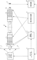
- FIG. 1 is a diagram showing a configuration of an MRTOF mass measuring apparatus 10 according to this embodiment.
- the MRTOF mass measuring apparatus 10 includes a flight tube 11, a detector 12, an ion trap 13 for injection into the flight tube 11, an ion trap 14 for storing sample ions, an ion trap 15 for storing reference ions, a logic sequencer 16, and an analog multiplexer. 17, a high-voltage switch 18, a high-voltage stabilized power source 19, and an analysis device 20.
- the flight tube 11 includes an ion mirror 11a on the incident side and an ion mirror 11b on the emission side.
- the ion mirror 11a is provided with an entrance 11c for introducing ions from the ejection ion trap 13 to the flight tube 11, and the ion mirror 11b is provided with an exit 11d for exiting from the flight tube 11 to the detector 12.
- the potential distribution in the ion mirrors 11a and 11b is controlled by the high voltage switch 18 controlling the voltage from the high voltage stabilizing power source 19 in accordance with an instruction from the logic sequencer 16.
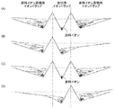
- 2A to 2C are diagrams schematically showing the potential distribution in the flight tube 11.
- the ion mirror 11a When ions are extracted from the ion trap 13 for injection and introduced into the flight tube 11, the ion mirror 11a is lowered by lowering the potential of the ion mirror 11a on the incident side, as shown in FIG. In FIG. 2A, the potential of the ion mirror 11a at the time of incidence is indicated by reference numeral 111. This potential 111 is lower than the potential 112 when the ion mirror 11a is closed, and is large enough to allow the introduced ions to pass through. The ion mirror 11b is closed and has a potential 113.
- the potential of the ion mirror 11a is raised and the ion mirror is closed as shown in FIG.
- the potential 112 of the ion mirror 11a is so large that ions cannot be overcome. Thereby, the ions in the flight tube 11 reciprocate between the ion mirror 11a and the ion mirror 11b.
- the potential of the ion mirror 11b is lowered to open the ion mirror.
- the potential of the ion mirror 11b at the time of emission is indicated by reference numeral 114.
- This potential 114 is lower than the potential 113 when the ion mirror 11b is closed, and is large enough to allow ions to pass through. Thereby, ions jump out of the flight tube 11 and are detected by the detector 12.
- the kinetic energy of ions introduced into the flight tube 11 is not always constant. Therefore, it is preferable to set the potential such that ions fly at different distances according to kinetic energy, and to make the flight time required for the round trip between the ion mirrors depend only on the mass of the ions.
- the detector 12 detects ions that jump out of the flight tube 11.
- existing parts such as a microchannel plate, a continuous dynode secondary electron multiplier, and a discontinuous dynode secondary electron multiplier can be used.
- the time when the ions are detected by the detector 12 is sent to the analysis device 20.
- FIG. 3 (A) and 3 (B) are diagrams showing configurations of the ejection ion trap 13, the sample ion storage ion trap 14, and the reference ion storage ion trap 15.
- FIG. 1 As the sample ion storage ion trap 14 and the reference ion storage ion trap 15, a linear high-frequency quadrupole ion trap can be generally used. A continuously incident ion beam is decelerated and cooled by an ion trap filled with a small amount of gas, and accumulated at the bottom of the DC potential generated in the axial direction. The axial DC potential is supplied by an analog multiplexer 17 and its timing is controlled by a logic sequencer 16. The accumulated ions can be transported to the adjacent ejection ion trap 13 at a predetermined timing.
- the ejection ion trap 13 is a device that cools the ions transported from the storage ion traps 14 and 15 and then pulsates them in the orthogonal direction at a predetermined timing.
- a parallel plate type electrode as shown in FIG. 3B includes a stripe 21 for applying a high-frequency potential and a central stripe 22 for applying a DC potential divided in the axial direction.
- a linear high-frequency ion trap having the following structure was used.
- An exit port 23 is provided at the center of the central electrode of the central stripe 22, and ions can be ejected from the ejection ion trap 13 in a direction perpendicular to the parallel plate.
- An ion beam generated in a sample ion supply source is introduced into the ion trap 14 (second ion trap) for storing sample ions after being decelerated and cooled. Sample ions are accumulated in the ion trap 14 and cooled.
- the analog multiplexer 17 controls the potential between the ion trap 13 and the ion trap 14 according to an instruction from the logic sequencer 16, so that the sample ions accumulated in the ion trap 14 are moved to the ion trap 13.
- the configuration of the reference ion storage ion trap 15 (third ion trap) is the same as that of the ion trap 14 for sample ions.
- Reference ions are stored in the storage ion trap 15.
- the reference ion has a mass that is almost the same as the sample ion, and selects an ion that can be used constantly.
- the frequency of supply from the reference ion supply source to the storage ion trap 15 is preferably adjusted so that one ion is supplied for each ion ejection cycle to be described later.
- the injection ion trap 13 (first ion trap) can supply sample ions from the storage ion trap 14 and can supply reference ions from the storage ion trap 15.
- the ejection ion trap 13 can cool accumulated ions and accelerate the accumulated ions at a timing instructed by the logic sequencer 16 to be ejected to the flight tube 11.
- the ejection ion trap 13 has a flat plate shape, and is configured to receive sample ions and reference ions from two opposite directions in the in-plane direction and eject ions in the vertical direction. Ions are ejected from the ejection ion trap 13 to the flight tube 11 by being controlled by the high voltage switch 18 in accordance with an instruction from the logic sequencer 16.
- the high voltage switch 18 performs ion injection from the ion trap 13 for injection to the flight tube 11, potential control of the ion mirror 11a, and potential control of the ion mirror 11b.
- the high voltage switch 18 can be configured using an existing high voltage FET (field effect transistor).
- FET field effect transistor
- the high voltage switch for controlling the ion mirrors 11a and 11b is configured using a photodiode switch.
- FIG. 4 is a circuit diagram of the high voltage switch 181 that controls the ion mirrors 11a and 11b.
- One ion mirror can be controlled by the circuit shown, and one high voltage switch 181 is used for each of the ion mirrors 11a and 11b.
- the high-voltage switch 181 turns on the positive-side high-voltage photodiode switch element 136 according to an input signal from the logic sequencer 16 and outputs a high-potential-side high voltage, or the negative-side high-voltage photodiode switch element. 146 is turned on to switch whether to output a positive voltage on the low potential side.
- a control signal for controlling the potential of the ion mirror 11 is input from the logic sequencer 16 to the input terminal 121.
- the control is performed so that the potential of the ion mirror takes a high potential (potential 112 or 113 in FIG. 2) when the control signal is on and a low potential (potential 111 or 114 in FIG. 2) when the control signal is off.
- the buffer 122 separates the input control signal into a non-inverted signal and an inverted signal.
- the non-inverted signal is input to the one-shot multivibrator 131.
- the one-shot multivibrator 131 is a circuit that outputs a short pulse signal when the input signal rises. This pulse signal is amplified and then input to a drive circuit 132 for driving the light emitting diode 133.
- the non-inverted signal output from the buffer 122 is input to a drive circuit 134 for driving the light emitting diode 135.
- the drive circuits 132 and 134 supply power to the light emitting diodes 133 and 135 to control the light emission of the light emitting diodes 133 and 135.
- the photodiode switch element 136 is arranged so as to be able to receive light emitted from the light emitting diodes 133 and 135, and when receiving light from the light emitting diode 133 or 135, outputs a high voltage on the high potential side to the output terminal 148.
- the light-emitting diode 133 is used for enhancing the brightness at the beginning of the light-emitting diode in a short period when the control signal rises.
- the light emission luminance of the light emitting diode 133 and the light emitting diode 135 may be the same or different.
- the supply current may be increased or the number of light emitting diodes may be increased.
- the photodiode switch element 136 when a control signal for controlling the potential of the ion mirror 11 to a high potential is input, the photodiode switch element 136 is irradiated with high-intensity light combining the light-emitting diode 133 and the light-emitting diode 135 at the time of rising of the control signal.
- the photodiode switch element 136 is driven by light from the light emitting diode 135 in a steady state.
- the potential of the ion mirror 11 rises sufficiently steeply when the control signal rises, and a stable high voltage potential is maintained during steady state.
- the configuration on the low potential side that is, the one-shot multivibrator 141, the drive circuit 142, the light emitting diode 143, the drive circuit 144, the light emitting diode 145, and the photodiode switch element 146 are the same as the configuration on the high potential side. The difference is that an inverted signal is supplied from the buffer 122 and the photodiode switch element 146 outputs a high voltage on the low potential side.
- a photodiode switch element is generated by high brightness light combining the light emitting diode 143 and the light emitting diode 145 when the control signal falls. 146 is driven, and the photodiode switch element 146 is driven by light from the light emitting diode 145 in a steady state. As a result, the potential of the ion mirror 11 falls sufficiently steeply when the control signal falls, and a stable high potential on the low potential side is maintained during steady state.
- the control signal input to the high voltage switch 181 from the logic sequencer 16 will be briefly described.
- the potential of the ion mirror 11 is high when the control signal is on, and the potential of the ion mirror 11 is low when the control signal is off. Therefore, an ON signal is supplied to the high voltage switch 181 at normal times.
- an off signal is supplied to the high voltage switch 181 that controls the ion mirror 11a.
- an off signal is supplied to the high voltage switch 181 that controls the ion mirror 11b during a period in which the potential of the ion mirror 11b is lowered.
- the analysis device 20 includes a computer (information processing device) including an arithmetic device such as a CPU, a main storage device, an auxiliary storage device, an input device, and an output device, and a TDC (time digital converter) that measures time of flight.
- a computer information processing device
- an arithmetic device such as a CPU
- main storage device such as a main storage device
- auxiliary storage device such as a main storage device
- an input device such as a keyboard
- an output device a TDC (time digital converter) that measures time of flight.
- the ions ejected to the flight tube 11 are detected by the detector 12 after reciprocating about 100 times.
- the time required for the above-described reciprocation is about 2 to 8 milliseconds, but taking the time required before and after that into consideration, it takes about 10 milliseconds for one injection.
- time-of-flight measurement is repeatedly performed on the sample ions, for example, for 20 minutes, the flight time of the reference ions is repeated for 5 minutes, and a measurement cycle consisting of these 25 minutes is repeatedly performed.
- sample ions and reference ions are alternately measured in a micro measurement cycle on the order of 10 milliseconds.
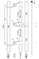
- FIG. 5 is a diagram showing a sequence relating to control such as accumulation of sample ions and reference ions in the ion trap, injection into the flight tube 11 and measurement of time of flight by the logic sequencer 16.
- the uppermost stage in the drawing represents the timing of ion accumulation in the ion trap 14 for storing sample ions and the supply of sample ions to the ion trap 13 for ejection.
- the second stage represents the accumulation of ions in the ejection ion trap 13 and the timing of ejection of the flight tube 11.
- the third level represents the timing of time-of-flight measurement in which ions are caused to fly into the flight tube 11 and detected by the detector 12.
- the lowermost stage represents the timing of ion storage in the reference ion storage ion trap 15 and supply of reference ions to the ejection ion trap 13.
- FIG. 5 shows a sequence of one measurement cycle including time-of-flight measurement of sample ions and time-of-flight measurement of reference ions.
- the analog multiplexer 17 controls the potential between the ion traps 13 and 14 based on a control command from the logic sequencer 16, and introduces sample ions accumulated in the ion trap 14 into the ejection ion trap 13.
- the movement of ions between ion traps is performed in a short time ( ⁇ 1 millisecond). Note that immediately after the movement of the accumulated sample ions is completed, accumulation of the sample ions supplied from the supply source to the ion trap 14 starts (period 206).
- FIG. 6A is a diagram showing potential distributions in the ion traps 13 to 15 and ions accumulated in each ion trap when sample ions are cooled in the ion trap 13 for injection.
- a potential barrier is provided between the ion traps 13 and 14 and between the ion traps 13 and 15, and no ion movement occurs between the ion traps.
- the ions accumulated in the ejection ion trap 13 are sample ions
- the sample ions are introduced into the ion trap 14 from the supply source
- the reference ions are introduced into the ion trap 15 from the supply source. Has been.
- the sample ions are accelerated in a pulse direction toward the flight tube 11 by applying a voltage in the vertical direction of the ion trap 13 based on a control command from the logic sequencer 16.
- the logic sequencer 16 lowers the potential of the ion mirror 11a on the incident side so that sample ions can be incident from the incident port 11c.
- the period 203 is a time-of-flight measurement period in which the sample ions are detected by the detector 12 after flying the sample ions in the flight tube 11.
- the potential of the ion mirror 11a on the incident side is raised, and the ion mirror is closed.
- the sample ions in the flight tube 11 reciprocate between the ion mirror 11a and the ion mirror 11b.
- the exit side ion mirror 11b is opened at a timing when the ions reciprocate a predetermined number of times, and the sample ions are ejected from the flight tube 11 and detected by the detector 12.
- reference ions accumulated in the ion trap 15 are introduced into the ejection ion trap 13 in the period 203.
- a specific operation is similar to that in the period 201. Further, after the movement of the reference ions from the ion trap 15 to the ejection ion trap 13 is completed, accumulation of reference ions from the supply source is started in the ion trap 15.
- FIG. 6B shows the potential distribution in the ion traps 13 to 15 and the ions accumulated in each ion trap when the reference ions are moved from the reference ion accumulation ion trap 15 to the ejection ion trap 13. It is. As shown in the figure, the potential barrier between the ion traps 13 and 15 is removed, and the reference ions accumulated in the ion trap 15 move to the ion trap 13 for ejection having a lower potential.
- FIG. 6C shows the potential distribution in the ion traps 13 to 15 and the ions accumulated in each ion trap when the reference ions are cooled in the ion trap 13 for ejection.
- the potential distribution is the same as in FIG. 6A, except that the ions accumulated and cooled in the ejection ion trap 13 are reference ions.
- a potential barrier is provided between the ion traps 13 and 14 and between the ion traps 13 and 15, and no ion movement occurs between the ion traps.
- the ions accumulated in the ejection ion trap 13 are reference ions
- sample ions are introduced from the supply source into the ion trap 14
- reference ions are introduced into the ion trap 15 from the supply source.
- the sample ion measurement period 203 is ended, and measurement of the next flight time can be started.
- the reference ions are ejected from the ejection ion trap 13 to the flight tube 11 based on the control command from the logic sequencer 16 to start the flight time measurement.
- the specific operation is the same as the measurement of sample ions (period 203).
- an ion trap for accumulation is prepared for each of the sample ions and the reference ions, and accumulation and cooling can be performed independently for the sample ions and the reference ions.
- the sample ions can be accumulated in the ion trap 14 for accumulation, and during the time of flight measurement of the sample ions (period 203, etc.) Accumulation in the ion trap 15 is possible. In this way, the accumulation of the other ion can be continued during the flight time of the other ion, so that two measurements can proceed simultaneously without loss.
- Mass determination process The mass determination process in the analysis device 20 will be described.
- the time of flight and the statistical error are obtained based on the time-of-flight distribution (time-of-flight spectrum) of the sample ions and the reference ions, and the mass of the sample ions is determined.
- the measurement device drifts during the measurement period (such as fluctuations in the high-voltage power supply or mechanical expansion / contraction of the device)
- the distribution expands or moves, so both statistical errors and systematic errors increase. Accuracy deteriorates.
- the time of flight measurement of the sample ion and the reference ion is performed almost at the same time, so the influence of the drift of the measurement device affects the time of flight distribution of the sample ion and the time of flight distribution of the reference ion. Equally affected, systematic errors are equally affected. Therefore, even if a large drift occurs during the measurement period, the measurement accuracy only deteriorates, and the measurement accuracy can be kept high.
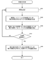
- FIG. 7 is a flowchart illustrating the mass determination process in the present embodiment.
- the analysis device 20 selects a measurement time t. A time between the measurement start time and the measurement end time may be selected for each appropriate time step.
- step S402 the analysis apparatus 20 evaluates the influence of drift from the time-of-flight distribution of the reference ions from time t- ⁇ / 2 to time t + ⁇ / 2.
- the influence of the drift on the flight time can be determined from the difference between the flight time of the reference ions obtained in advance by obtaining the flight time of the reference ions based on the flight time distribution within the period.
- step S403 the analysis apparatus 20 corrects the influence of the drift obtained in step S402 on the flight time of the sample ions and the flight time of the reference ions at time t. If the time step in step S401 is ⁇ t, the flight time measured between time t ⁇ t / 2 and t + ⁇ t / 2 may be corrected similarly.
- step S404 it is determined whether the above processing has been performed for all the measurement periods. If the processing has not been completed, the process returns to step S401 and the same processing is repeated for the next time step. When the process for the entire period is completed, the process proceeds to step S405.
- step S405 the analysis apparatus 20 determines the mass of the sample ions based on the time-of-flight distribution including the time of flight of the sample ions and the reference ions corrected as described above.
- FIG. 8A-1 shows the time-of-flight measurement result of the reference ion 133 Cs + at each measurement time.
- the horizontal axis represents the measurement time
- the vertical axis represents the flight time.
- the vertical axis is in units of nanoseconds with 7,924,706.5 nanoseconds as the origin.
- 57 ppm time-of-flight drift occurs in the measurement for 1080 seconds.
- FIG. 8A-2 also shows the time change of the flight time of the sample ion 138 Ba + , and it can be seen that it has the same time dependency.
- FIG. 8 (B-1, B-2) shows the number of detected reference ions 133 Cs + and sample ions 138 Ba + for each measurement time.
- the change in the number of detections is caused by the change in the ion beam intensity, and it can be seen from the figure that the ion beam intensity changes during the measurement period.
- FIG. 8 (C-1, C-2, D-1, D-2) shows the time-of-flight distribution of each ion.
- 8 (C-1, D-1) shows the time-of-flight distribution of reference ions 133 Cs + (with and without correction processing)
- FIG. 8 (C-2, D-2) shows the time of flight of sample ions 138 Ba + .
- Distribution (no correction processing and with correction)
- the horizontal axis shows the flight time in nanosecond units with reference time (7,925,260 nanoseconds and 8,072,953 nanoseconds, respectively), and the vertical axis shows ion unit time (3.2 nanoseconds here) ).
- FIGS. 9A to 9E show the results of the same measurement as described above with the high-voltage power supply stabilization mechanism and its temperature stabilization mechanism turned off under different conditions.
- FIG. 9A shows the time-of-flight measurement result of the reference ion 133 Cs + at each measurement time. Since the stabilization mechanism was turned off immediately after the start of measurement, a jump occurred in the measurement result of the flight time, and a large fluctuation occurred thereafter. Specifically, 25 ppm of flight time drift occurs in one hour measurement.
- FIGS. 9B and 9C show the time-of-flight distributions of the sample ions 138 Ba + and the reference ions 133 Cs + before the correction process, respectively. As can be seen from the figure, the distribution is very wide and two peaks are seen.
- FIGS. 9D and 9E show the time-of-flight distribution of the sample ion 138 Ba + and the reference ion 133 Cs + after the correction process, respectively.
- the influence of drift is corrected to obtain a flight time distribution having a relatively steep peak.
- the time-of-flight mass spectrometer according to the present embodiment can introduce ions from two ion traps for sample ions and reference ions with respect to the ion trap for ejection. As a result, it is possible to alternately fly the sample ions and the reference ions once. Furthermore, during the time of flight measurement of one, the other ion can be accumulated. Therefore, the measurement efficiency is improved.
- the influence of drift is evaluated using the time-of-flight distribution of reference ions obtained in a relatively short period, and the influence of drift is corrected. This also improves the accuracy of measurement.
- the high voltage switch 181 is configured using a photodiode switch, noise generated during switching can be suppressed, and the voltage waveform of the ion mirror after switching can be kept stable. it can. Highly accurate mass measurement is possible due to the stability of the voltage waveform.
- a high voltage switch is configured using a high voltage FET, a high-speed switch (about 0.1 microsecond) is possible, but the voltage waveform after the switch is not stabilized due to ringing.
- the switching speed is about several microseconds, but the time required for one round trip of ions in the flight tube 11 is about 20 to 80 microseconds under typical conditions. Therefore, the high voltage switch 181 of this embodiment is sufficiently fast and has excellent stability.
- the high voltage switch 181 of the present embodiment can arrange the high voltage photodiode switch electrostatically completely independently by arranging the logic circuit to the light emitting diode at the ground potential. Therefore, even if an event such as a short-time discharge occurs, the circuit is not destroyed, and the high-voltage switch can be used stably for a long time.
- the high voltage switch of this embodiment can arrange the high voltage photodiode switch electrostatically completely independently by arranging the logic circuit to the light emitting diode at the ground potential. Therefore, even if an event such as a short-time discharge occurs, the circuit is not destroyed, and the high-voltage switch can be used stably for a long time.
- the high voltage switch of this embodiment When a high voltage FET is used, the element frequently fails and needs to be replaced when a surge occurs, but such a failure can be avoided by using the high voltage switch of this embodiment.
- the sample ion and the reference ion are alternately ejected once and the flight time is measured. While the flight time of one ion is measured, the other ion is accumulated and If cooling is possible, there are cases where results of improved measurement accuracy and measurement efficiency can be obtained without necessarily injecting alternately. For example, consider a case where sample ions are very rare but have a sufficiently long lifetime. This corresponds to the measurement of long-lived unstable nuclei and environmental trace materials. In this case, it is preferable to fly the reference ions about 50 times while collecting the sample ions in the storage ion trap for a long period of about several seconds and flying them once.
- the reference ions can be measured in a short time so that the statistical error is sufficiently reduced without reducing the efficiency of the sample ion measurement. This allows for correction of the drift with a shorter time frequency, thus allowing for high accuracy measurements under wider conditions.
- a rare unstable nucleus with an extremely short lifetime (several milliseconds). In this case, there is no effect even if it is accumulated in the ion trap for sample accumulation for a long time, so that it is more efficient to repeat the flight of sample ions as frequently as possible.
- the measurement of the reference ions is also necessary, for example, a method of maintaining efficiency, accuracy, and accuracy by taking a special time structure in which the next flight after detecting the target rare nucleus is assigned to the flight of the reference ions is effective.
- the method of using a single reference ion in the multiple reflection (closed) time-of-flight mass measurement method is described as an example, but multiple reflection and single reference ion are essential. It is not a simple configuration.
- the present invention can also be applied when using a plurality of reference ions. In this case, a sample ion and two types (or more) of reference ions can be supplied to the ion trap for ejection, and the flight time is measured by ejecting these ions alternately.
- the present invention is not limited to a closed multiple reflection type as long as it is a time-of-flight measurement method, and may be any one of an open multiple reflection type, a linear type, a reflector (single reflection) type, an open circuit and a closed track type Applicable.
- the embodiment described above is a preferred embodiment in terms of mass measurement of rare particles. Since rare particles are rarely generated, there is a demand for measurement without reducing efficiency as much as possible. In the above embodiment, the flight time can be measured without wasting generation of rare particles. In addition, since rare particles are rarely ejected in most injections, the rare particles need to be measured for a long time, and it is difficult to avoid the measurement being affected by drift. Therefore, the above-described embodiment that enables measurement with high accuracy and enables high-precision measurement by the drift correction processing is useful for mass measurement of rare particles.
- the above embodiment can measure the flight time in about several milliseconds, it is possible to measure short-lived nuclei having a lifetime of 0.1 seconds or less or very heavy nuclei, and such rare particles can be measured. Since it can measure with high efficiency, it is particularly useful for mass measurement of such particles.
- the present invention is not limited to the measurement of short-lived particles, and can be applied to the measurement of arbitrary charged particles.
- the present invention can be preferably applied to molecular composition analysis and trace substance analysis. Even in the severe measurement environment assumed for such applications, it is possible to maintain high accuracy and high accuracy even when it is difficult to maintain the stability of the apparatus and the high-voltage power supply.
- Flight tube 12 Detector 13: Ion trap for injection 14: Ion trap for sample ion accumulation 15: Ion trap for reference ion accumulation
Landscapes
- Chemical & Material Sciences (AREA)
- Physics & Mathematics (AREA)
- Analytical Chemistry (AREA)
- Health & Medical Sciences (AREA)
- Spectroscopy & Molecular Physics (AREA)
- Life Sciences & Earth Sciences (AREA)
- Biochemistry (AREA)
- Electrochemistry (AREA)
- Chemical Kinetics & Catalysis (AREA)
- Molecular Biology (AREA)
- General Health & Medical Sciences (AREA)
- General Physics & Mathematics (AREA)
- Immunology (AREA)
- Pathology (AREA)
- Other Investigation Or Analysis Of Materials By Electrical Means (AREA)
- Electron Tubes For Measurement (AREA)
Abstract
第1のイオントラップに蓄積されたイオンを加速して飛行管に導入し飛行時間を測定することによって前記イオンの質量を測定する飛行時間測定式質量測定装置であって、測定対象イオンを蓄積し前記第1のイオントラップに導入可能な第2のイオントラップと、参照用イオンを蓄積し前記第1のイオントラップに導入可能な第3のイオントラップと、を備える。(1)前記第2のイオントラップから前記第1のイオントラップへの前記測定対象イオンの導入および前記測定対象イオンの飛行時間測定と、(2)前記第3のイオントラップから前記第1のイオントラップへの前記参照用イオンの導入および前記参照用イオンの飛行時間測定と、を所定のパターン(例えば1回ずつ)で交互に行う制御手段をさらに備えることが好ましい。
Description
本発明は、飛行時間測定式質量分析法(Time-of-Flight Mass Spectrometry)に関し、特に、飛行時間測定式質量分析法を用いた長時間の測定であっても効率を損なうことなく高確度な測定を行う手法に関連する。
飛行時間型質量分析の一つとして多重反射型飛行時間測定式質量分析(Multi-Reflection Time-of-Flight Mass Spectrometry: MRTOFMS)が知られている(非特許文献1、特許文献1)。多重反射型飛行時間測定式質量分析では、試料イオンを飛行管に打ち出して試料イオンを飛行管両端のイオンミラー間で複数回往復させ、適当な時間の経過後に飛行管出口を開けて、打ち出しから検出までの飛行時間を測定する。飛行時間は試料イオンの質量の1/2乗に比例するので、質量が既知の参照イオンの飛行時間と比較することで、試料イオンの質量を測定できる。
飛行時間測定式質量分析においては、上記のように質量が既知でかつ定常的に測定できる参照イオンの飛行時間の測定が必要である。なお、飛行時間測定方式では、イオンの打ち出し時刻の不定性により2種類の参照イオンの測定が必要であるが、非特許文献2に示されるように、多重反射型飛行時間測定式質量分析では、1種類の参照イオンのみを用いて試料イオンの質量を決定可能である。
多重時間型飛行時間測定式質量分析では、非特許文献2のように、試料イオンの測定と参照イオンの測定を、別々に交互に行うことが一般的であった。このように交互に測定を行うことで、参照イオンの飛行時間から測定装置のドリフトを補償できる。なお、稀に、たまたま試料イオンと参照イオンが混在し同時に測定できる場合には、その参照イオンの飛行時間を用いて測定装置のドリフトを補償することが可能であるが、一般的ではない。
H. Wollnik et al, Int. J. Mass Spectrometry and Ion Processes, 96 (1990) 267.
Y. Ito et al, Phys, Rev. C 88 (2013) 011306(R).
Y. Ito et al., Nuclear Instruments and Methods in Physics Research B 317 (2013) 544.
従来の交互測定方式には次のような問題がある。第一に、参照イオンの測定時には試料イオン(測定対象イオン)の測定が行えず、その分だけ測定の効率が低下する。例えば、試料イオンの測定を20分間行い、参照イオンの測定を5分間行うというサイクルを繰り返した場合、少なくとも測定期間の20%において試料イオンの測定が行えない。
第二に、測定装置のドリフトは様々な原因および異なる時定数を持っていることが一般的である。したがって、試料イオンの測定時と参照イオンの測定時の測定条件の同一性を担保することができず、ドリフトの影響を完全に補償することは困難であった。
このような問題を考慮して、本発明は、飛行時間測定式質量分析において、従来よりも測定効率が高く、かつ、高精度・高確度な測定を可能とする手法を提供することを目的とする。
本発明の第一の態様は、第1のイオントラップに蓄積されたイオンをパルス的に加速して飛行管に導入し飛行時間を測定することによって前記イオンの質量を測定する飛行時間測定式質量分析装置であって、以下の構成を有することを特徴とする。
すなわち、本態様に係る飛行時間測定式質量測定装置は、測定対象イオンの供給源から供給された測定対象イオンを蓄積し、前記第1のイオントラップに前記測定対象イオンを導入可能な第2のイオントラップと、参照用イオンの供給源から供給された参照用イオンを蓄積し、前記第1のイオントラップに前記参照用イオンを導入可能な第3のイオントラップと、備える。本態様において、第1のイオントラップは、第2のイオントラップからの測定対象イオンの導入と、第3のイオントラップからの参照イオンの導入が行えるように構成される。
このように、第1のイオントラップに対して、第2および第3のイオントラップからイオンを導入可能としたことで、本態様の飛行時間測定式質量測定装置は、制御手段によって、(1)前記第2のイオントラップから前記第1のイオントラップへの前記測定対象イオンの導入および前記測定対象イオンの飛行時間測定と、(2)前記第3のイオントラップから前記第1のイオントラップへの前記参照用イオンの導入および前記参照用イオンの飛行時間測定と、を所定のパターンで交互に行うように構成できる。ここで、所定のパターンは、任意のパターンであって構わないが、上記(1)と(2)の動作を1回ずつ交互に行うパターンであることが好適である。
従来技術では数分から数時間単位のマクロな時間構造において交互に測定を行っているが、本態様では1回の打ち出しおよび飛行時間の測定という10ミリ秒オーダーの時間構造において交互に測定を行う。測定対象イオンと参照イオンの蓄積用に第2のイオントラップと第3のイオントラップがそれぞれ用意されているので、試料イオンと参照イオンのうち、一方のイオンの飛行時間測定中に、他方のイオンのイオントラップへの蓄積が可能である。具体的には、参照イオンの打ち出しから飛行時間の測定を行っている期間のあいだ、測定対象イオンをその供給源から第2のイオントラップに供給して蓄積を継続できる。同様に、測定対象イオンの打ち出しから飛行時間の測定を行っている期間のあいだ、参照イオンをその供給源から第3のイオントラップに供給して蓄積を継続できる。したがって、測定効率を損なうことなく、測定対象イオンと参照イオンの測定を同時に行うことができる。
本態様の飛行時間測定式質量測定装置は、前記測定対象イオンの飛行時間を、当該飛行時間の測定時を含む所定期間内の参照用イオンの飛行時間の測定結果に基づいて補正する補正手段をさらに備える、ことも好適である。参照イオンの発生頻度は調整可能であるため、参照イオンの測定は毎回行うようにできる。したがって、参照イオンの飛行時間は短い時間でも十分に統計的に意味のある測定(飛行時間分布の取得)が行える。これを利用すると、短い時間幅において参照イオンの飛行時間を用いて装置のドリフトを追尾することが可能となり、非常に長い時間かかる測定であっても、測定の確度と精度を保つことが可能である。
本発明は、上記の工程を含む飛行時間測定式質量測定方法として捉えることもできる。すなわち、本発明の第二の態様は、第1のイオントラップに蓄積されたイオンをパルス的に加速して飛行管に導入し飛行時間を測定することによって前記イオンの質量を測定する飛行時間測定式質量測定装置を用いた、飛行時間測定式質量測定方法であって、
測定対象イオンの供給源から供給された測定対象イオンを第2のイオントラップに蓄積するステップと、
参照用イオンの供給源から供給された参照用イオンを第3のイオントラップに蓄積するステップと、
(1)前記第2のイオントラップから前記第1のイオントラップへの前記測定対象イオンの導入および前記測定対象イオンの飛行時間測定と、(2)前記第3のイオントラップから前記第1のイオントラップへの前記参照用イオンの導入および前記参照用イオンの飛行時間測定と、を所定のパターンで交互に行うステップと、
を含む、ことを特徴とする。
測定対象イオンの供給源から供給された測定対象イオンを第2のイオントラップに蓄積するステップと、
参照用イオンの供給源から供給された参照用イオンを第3のイオントラップに蓄積するステップと、
(1)前記第2のイオントラップから前記第1のイオントラップへの前記測定対象イオンの導入および前記測定対象イオンの飛行時間測定と、(2)前記第3のイオントラップから前記第1のイオントラップへの前記参照用イオンの導入および前記参照用イオンの飛行時間測定と、を所定のパターンで交互に行うステップと、
を含む、ことを特徴とする。
本発明によれば、飛行時間測定式質量分析において、従来よりも測定効率が高く、かつ、高確度な測定が可能となる。
[測定原理]
以下、本発明の実施形態に係る多重反射型飛行時間測定式質量測定装置(以下、MRTOF質量測定装置とも称する)について説明する。本実施形態に係るMRTOF質量測定装置は、非特許文献2のように単一の参照イオンを用いて測定を行うので、単一の参照イオンのみによって試料イオン(測定対象イオン)の質量測定が行えることを簡単に説明する。
以下、本発明の実施形態に係る多重反射型飛行時間測定式質量測定装置(以下、MRTOF質量測定装置とも称する)について説明する。本実施形態に係るMRTOF質量測定装置は、非特許文献2のように単一の参照イオンを用いて測定を行うので、単一の参照イオンのみによって試料イオン(測定対象イオン)の質量測定が行えることを簡単に説明する。
イオンの飛行時間は、次式のようにイオンの質量の1/2乗に比例する。

ここで、ToFが飛行時間、mが質量、Lが飛行長、Kが運動エネルギーである。
ここで、ToFが飛行時間、mが質量、Lが飛行長、Kが運動エネルギーである。
したがって、試料イオンの質量mxは、その飛行時間txと、質量が既知の参照イオンの質量mrおよびその飛行時間trを用いて求めることができる。

ここで、t0は飛行時間の時間原点と実際のイオンの射出時刻との差である。一般に、イオン射出時刻を厳密に決定することはできないので、試料イオンの質量決定のためには2種類の試料イオンの飛行時間を測定する必要がある。
ここで、t0は飛行時間の時間原点と実際のイオンの射出時刻との差である。一般に、イオン射出時刻を厳密に決定することはできないので、試料イオンの質量決定のためには2種類の試料イオンの飛行時間を測定する必要がある。
しかしながら、MRTOF質量測定装置では飛行長Lが長く、また、試料イオンと参照イオンの質量がほぼ等しいことから、tx~tr>>t0が成立する。したがって、下記の近似が十分高い精度で成立し、単一の参照イオンのみを用いて試料イオンの質量を決定できる。
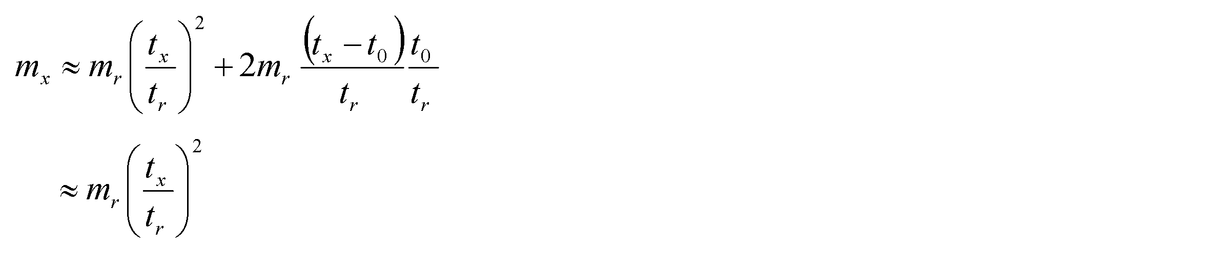
[装置構成]
図1は、本実施形態に係るMRTOF質量測定装置10の構成を示す図である。MRTOF質量測定装置10は、飛行管11、検出器12、飛行管11への射出用イオントラップ13、試料イオンの蓄積用イオントラップ14、参照イオンの蓄積用イオントラップ15、ロジックシーケンサー16、アナログマルチプレクサ17、高電圧スイッチ18、高圧安定化電源19、解析装置20を備える。
図1は、本実施形態に係るMRTOF質量測定装置10の構成を示す図である。MRTOF質量測定装置10は、飛行管11、検出器12、飛行管11への射出用イオントラップ13、試料イオンの蓄積用イオントラップ14、参照イオンの蓄積用イオントラップ15、ロジックシーケンサー16、アナログマルチプレクサ17、高電圧スイッチ18、高圧安定化電源19、解析装置20を備える。
飛行管11は、入射側のイオンミラー11a、射出側のイオンミラー11bを含む。イオンミラー11aには射出用イオントラップ13から飛行管11にイオンを導入するための入射口11c、イオンミラー11bには飛行管11から検出器12に射出するための射出口11dが設けられる。イオンミラー11a、11b内のポテンシャル分布の制御は、高電圧スイッチ18がロジックシーケンサー16からの指示に従って高圧安定化電源19からの電圧を制御することによって行われる。
イオンミラー11a、11b内のポテンシャル分布の制御について図2(A)~図2(C)を参照して説明する。図2(A)~図2(C)は、飛行管11内のポテンシャル分布を模式的に示す図である。
射出用イオントラップ13からイオンを引き出して飛行管11に導入する際には、図2(A)に示すように、入射側のイオンミラー11aのポテンシャルを下げてイオンミラーを空けておく。図2(A)においては、入射時のイオンミラー11aのポテンシャルは符号111によって示される。このポテンシャル111は、イオンミラー11aの閉鎖時のポテンシャル112によりも低く、導入されたイオンが通過できる程度の大きさである。なお、イオンミラー11bは閉じており、ポテンシャル113を有する。
そして、入射されたイオンが入射側のイオンミラー11aに戻る前までに、図2(B)に示すように、イオンミラー11aのポテンシャルを上げてイオンミラーを閉じる。イオンミラー11aのポテンシャル112はイオンが乗り越えられない程度の大きさである。これにより、飛行管11内のイオンは、イオンミラー11aとイオンミラー11bのあいだを往復する。
イオンが所定回数(例えば百回程度)往復するタイミングで、図2(C)に示すように、イオンミラー11bのポテンシャルを下げてイオンミラーを開放する。図2(C)においては、出射時のイオンミラー11bのポテンシャルは符号114によって示される。このポテンシャル114は、イオンミラー11bの閉鎖時のポテンシャル113によりも低く、イオンが通過できる程度の大きさである。これにより、イオンは飛行管11から飛び出し、検出器12によって検出される。
なお、飛行管11に導入されるイオンの運動エネルギーは一定とは限らない。そこで、運動エネルギーに応じて異なる距離をイオンが飛行するようなポテンシャルとし、イオンミラー間の往復に要する飛行時間がイオンの質量のみに依存するようにすることが好ましい。
検出器12は、飛行管11から飛び出すイオンを検出する。検出器12として、マイクロチャンネルプレート、連続ダイノード二次電子増倍管、非連続ダイノード二次電子増倍管など既存の部品を採用できる。検出器12によってイオンが検出された時刻は、解析装置20に送られる。
図3(A)、3(B)は、射出用イオントラップ13、試料イオン蓄積用イオントラップ14、および参照イオン蓄積用イオントラップ15の構成を示す図である。試料イオン蓄積用イオントラップ14および参照イオン蓄積用イオントラップ15は、一般的に線型高周波四重極イオントラップを用いることができる。連続的に入射されるイオンビームを少量のガスに満ちたイオントラップで減速冷却して、軸方向に生成した直流ポテンシャルの底に蓄積する。軸方向の直流ポテンシャルはアナログマルチプレクサ17によって供給され、そのタイミングはロジックシーケンサー16で制御される。蓄積されたイオンは所定のタイミングで隣の射出用イオントラップ13に輸送することができる。
射出用イオントラップ13は、蓄積用イオントラップ14,15から輸送されたイオンを冷却した後、所定のタイミングで直交方向にパルス的に打ち出す装置である。様々な構造を取りうるが、実施形態では、図3(B)に示すような、平行平板型の電極に、高周波電位を与えるストライプ21と軸方向に分割した直流電位を与える中心のストライプ22からなる構造の線型高周波イオントラップを用いた。中心のストライプ22の中央電極の中心に射出口23が設けられており、射出用イオントラップ13から、平行平板と直交する方向にイオンを射出できる。中心のストライプ状の電極に与える電位を制御することによって、上方からの入射、下方からの入射、中心から直角方向へのパルス的射出を所定のタイミングで行うことができる(非特許文献3参照)。
試料イオンの蓄積用イオントラップ14(第2のイオントラップ)には、試料イオンの供給源において発生させたイオンビームが減速・冷却された後に導入される。イオントラップ14には、試料イオンが蓄積され冷却される。アナログマルチプレクサ17が、ロジックシーケンサー16からの指示に従ってイオントラップ13とイオントラップ14のあいだのポテンシャルを制御することで、イオントラップ14に蓄積された試料イオンが、イオントラップ13に移動させられる。
参照イオンの蓄積用イオントラップ15(第3のイオントラップ)の構成は、試料イオン用のイオントラップ14と同様である。蓄積用イオントラップ15には、参照イオンが蓄積される。参照イオンは、試料イオンとほぼ同一の質量を有し、定常的に利用可能なイオンを選択する。参照イオンの供給源から蓄積用イオントラップ15への供給頻度は、後述するイオンの射出サイクルごとに1つのイオンが供給されるように調整しておくことが好ましい。
射出用イオントラップ13(第1のイオントラップ)は、蓄積用イオントラップ14から試料イオンの供給が可能であり、蓄積用イオントラップ15から参照イオンの供給が可能である。また、射出用イオントラップ13は、蓄積されたイオンを冷却し、ロジックシーケンサー16から指示されたタイミングで蓄積されたイオンをパルス的に加速して飛行管11に射出可能である。本実施形態においては、射出用イオントラップ13は平板形状であり、面内方向の互いに対向する2方向から試料イオンと参照イオンの供給を受け、垂直方向に対してイオンを射出する構成である。射出用イオントラップ13から飛行管11へのイオンの射出は、ロジックシーケンサー16からの指示に従って高電圧スイッチ18が制御することによって行われる。
高電圧スイッチ18は、射出用イオントラップ13から飛行管11へのイオン射出、イオンミラー11aのポテンシャル制御、イオンミラー11bのポテンシャル制御を行う。高電圧スイッチ18は、既存の高電圧FET(電界効果トランジスタ)を用いて構成することができる。しかしながら、イオンミラー11a、11bのポテンシャルが揺らぐとイオンの飛行時間にばらつきが生じるため、イオンミラー11a、11bのポテンシャル制御には高い安定度が求められる。そこで、本実施形態では、イオンミラー11a、11bを制御するための高電圧スイッチを、フォトダイオードスイッチを用いて構成する。
図4は、イオンミラー11a、11bを制御する高電圧スイッチ181の回路図である。図示した回路によって1つのイオンミラーを制御でき、イオンミラー11a、11bにそれぞれに1つの高電圧スイッチ181が用いられる。高電圧スイッチ181は、ロジックシーケンサー16からの入力信号にしたがって、正極側の高電圧フォトダイオードスイッチ素子136をオンにして高電位側の高電圧を出力するか、負極側の高電圧フォトダイオードスイッチ素子146をオンにして低電位側の正電圧を出力するかを切り替える。
入力端子121には、イオンミラー11のポテンシャルを制御するための制御信号が、ロジックシーケンサー16から入力される。ここでは、制御信号がオンのときにイオンミラーのポテンシャルが高電位(図2のポテンシャル112または113)をとり、オフの時に低電位(図2のポテンシャル111または114)をとるように制御されるものとする。
緩衝器122は、入力された制御信号を、非反転の信号と反転の信号に分離する。非反転信号は、ワンショットマルチバイブレータ131に入力される。ワンショットマルチバイブレータ131は、入力信号の立ち上がり時に短いパルス信号を出力する回路である。このパルス信号は増幅された後に、発光ダイオード133を駆動するためのドライブ回路132に入力される。また、緩衝器122から出力された非反転信号は、発光ダイオード135を駆動するためのドライブ回路134に入力される。
ドライブ回路132、134は、信号入力があると発光ダイオード133、135に電力を供給して、発光ダイオード133、135の発光を制御する。フォトダイオードスイッチ素子136は、発光ダイオード133および135が発する光を受光可能に配置されており、発光ダイオード133または135からの光を受光しているときに、高電位側の高電圧を出力端子148からイオンミラー11に出力する。
発光ダイオード133は、制御信号の立ち上がり時の短期間、すなわち発光ダイオードの光り始めの輝度を増強するために用いられる。発光ダイオード133と発光ダイオード135の発光輝度は同じであってもよいし異なっていてもよい。いずれか一方の発光ダイオードの発光輝度を大きくするためには、供給電流を強くしてもよいし、発光ダイオードの数を多くしてもよい。
このような構成により、イオンミラー11のポテンシャルを高電位に制御する制御信号が入力されると、制御信号の立ち上がり時には発光ダイオード133と発光ダイオード135を合わせた高輝度な光によってフォトダイオードスイッチ素子136が駆動され、定常時は発光ダイオード135からの光によってフォトダイオードスイッチ素子136が駆動される。これにより、制御信号の立ち上がり時には十分急峻にイオンミラー11のポテンシャルが立ち上がり、定常時には安定な高圧電位が保たれる。
また、低電位側の構成、すなわち、ワンショットマルチバイブレータ141、ドライブ回路142、発光ダイオード143、ドライブ回路144、発光ダイオード145、フォトダイオードスイッチ素子146は、高電位側の構成と同様である。異なる点は、緩衝器122から反転信号が供給される点と、フォトダイオードスイッチ素子146が低電位側の高電圧を出力する点である。
このような構成により、イオンミラー11のポテンシャルを低電位に制御する制御信号が入力されると、制御信号の立ち下がり時には発光ダイオード143と発光ダイオード145を合わせた高輝度な光によってフォトダイオードスイッチ素子146が駆動され、定常時は発光ダイオード145からの光によってフォトダイオードスイッチ素子146が駆動される。これにより、制御信号の立ち下がり時には十分急峻にイオンミラー11のポテンシャルが立ち下がり、定常時には安定な低電位側の高圧電位が保たれる。
ロジックシーケンサー16から高電圧スイッチ181に入力される制御信号について簡単に説明する。本実施形態では、制御信号がオンの場合にイオンミラー11のポテンシャルが高電位になり、制御信号がオフの場合にイオンミラー11のポテンシャルが低電位となる。したがって、通常時には高電圧スイッチ181にはオン信号が供給される。図2(A)に示すようにイオンミラー11aのポテンシャルを下げるには、イオンミラー11aを制御する高電圧スイッチ181へオフ信号が供給される。同様に、図2(C)に示すようにイオンミラー11bのポテンシャルを下げる期間には、イオンミラー11bを制御する高電圧スイッチ181へオフ信号が供給される。
解析装置20は、CPUなどの演算装置、主記憶装置、補助記憶装置、入力装置、出力装置などを備えるコンピュータ(情報処理装置)と、飛行時間を測定するTDC(時間ディジタルコンバータ)からなり、CPUがプログラムを実行することにより、検出器12によって測定された試料イオンおよび参照イオンの飛行時間データを記憶装置に蓄積し、その値から、試料イオンの質量の決定を行う。
[測定シーケンス]
次に、本実施形態におけるイオンの蓄積や射出に関する制御について説明する。本実施形態では、飛行管11に射出されたイオンを約100回往復させた後に、検出器12により検出する。上記の往復に必要な時間は2乃至8ミリ秒程度であるが、その前後に必要な時間を考慮に入れると1回の射出について10ミリ秒程度の時間がかかる。従来技術では、試料イオンに飛行時間測定を例えば20分間繰り返して行い、参照イオンの飛行時間を5分間繰り返して行い、これらの25分間からなる測定サイクルを繰り返し実行している。これに対して、本実施形態では、10ミリ秒オーダーのミクロな測定サイクルにおいて試料イオンと参照イオンの測定を交互に行う。
次に、本実施形態におけるイオンの蓄積や射出に関する制御について説明する。本実施形態では、飛行管11に射出されたイオンを約100回往復させた後に、検出器12により検出する。上記の往復に必要な時間は2乃至8ミリ秒程度であるが、その前後に必要な時間を考慮に入れると1回の射出について10ミリ秒程度の時間がかかる。従来技術では、試料イオンに飛行時間測定を例えば20分間繰り返して行い、参照イオンの飛行時間を5分間繰り返して行い、これらの25分間からなる測定サイクルを繰り返し実行している。これに対して、本実施形態では、10ミリ秒オーダーのミクロな測定サイクルにおいて試料イオンと参照イオンの測定を交互に行う。
図5は、ロジックシーケンサー16による試料イオンおよび参照イオンのイオントラップへの蓄積や飛行管11への射出、飛行時間の測定等の制御に関するシーケンスを表す図である。図中の最上段は試料イオンの蓄積用イオントラップ14でのイオン蓄積および射出用イオントラップ13への試料イオンの供給のタイミングを表す。2段目は、射出用イオントラップ13におけるイオンの蓄積および飛行管11の射出へのタイミングを表す。3段目は、飛行管11内にイオンを飛行させ検出器12によってイオンを検出する飛行時間測定のタイミングを表す。最下段は、参照イオンの蓄積用イオントラップ15でのイオン蓄積および射出用イオントラップ13への参照イオンの供給のタイミングを表す。
図5には、試料イオンの飛行時間測定と参照イオンの飛行時間測定からなる1測定サイクルのシーケンスが示されている。期間201において、ロジックシーケンサー16からの制御指令に基づいてアナログマルチプレクサ17がイオントラップ13,14間のポテンシャルを制御して、イオントラップ14に蓄積された試料イオンを射出用イオントラップ13に導入する。イオントラップ間のイオンの移動は短時間(<1ミリ秒)で行われる。なお、蓄積された試料イオンの移動が完了した直後から、イオントラップ14には供給源から供給される試料イオンの蓄積が開始する(期間206)。
期間202において、試料イオンは射出用イオントラップ13に蓄積され、冷却される。図6(A)は、試料イオンを射出用イオントラップ13において冷却している際の、イオントラップ13~15におけるポテンシャル分布および各イオントラップに蓄積されているイオンを示す図である。図6(A)に示すように、イオントラップ13と14のあいだ、およびイオントラップ13および15のあいだにポテンシャル障壁が設けられ、イオントラップ間でのイオンの移動は生じない。また、この時点では射出用イオントラップ13に蓄積されているイオンは試料イオンであり、イオントラップ14には供給源から試料イオンが導入されており、イオントラップ15には供給源から参照イオンが導入されている。
射出用イオントラップ13における冷却期間202が終了すると、ロジックシーケンサー16からの制御指令に基づいて、イオントラップ13の垂直方向に電圧を掛けて試料イオンを飛行管11に向けてパルス的に加速させる。また、ロジックシーケンサー16は同時に、入射側のイオンミラー11aのポテンシャルを下げて、入射口11cからの試料イオンの入射を可能とする。
期間203は、飛行管11内で試料イオンを飛行させた後に検出器12によって試料イオンを検出する飛行時間測定期間である。飛行管11に試料イオンを導入した後、入射側のイオンミラー11aのポテンシャルを上げ、イオンミラーを閉じる。これにより、飛行管11内の試料イオンは、イオンミラー11aとイオンミラー11bのあいだを往復する。イオンが所定回数往復するタイミングで射出側イオンミラー11bを開放して、試料イオンは飛行管11から飛び出し検出器12によって検出される。
試料イオンの飛行時間測定期間203が完了する前に、期間203において、イオントラップ15に蓄積された参照イオンが射出用イオントラップ13に導入される。具体的な動作は、期間201の場合と同様である。また、イオントラップ15から射出用イオントラップ13への参照イオンの移動が完了した後、イオントラップ15には供給源からの参照イオンの蓄積が開始する。
図6(B)は、参照イオンを参照イオン蓄積用イオントラップ15から射出用イオントラップ13に移動させる際の、イオントラップ13~15におけるポテンシャル分布および各イオントラップに蓄積されているイオンを示す図である。図に示すように、イオントラップ13および15のあいだのポテンシャル障壁が取り除かれ、イオントラップ15に蓄積された参照イオンが、より低ポテンシャルの射出用イオントラップ13に移動する。
期間204において、参照イオンは射出用イオントラップ13に蓄積され、冷却される。図6(C)は、参照イオンを射出用イオントラップ13において冷却している際の、イオントラップ13~15におけるポテンシャル分布および各イオントラップに蓄積されているイオンを示す図である。ポテンシャル分布は図6(A)の場合と同様であるが、射出用イオントラップ13に蓄積・冷却されているイオンが、参照イオンである点が異なる。図6(A)に示すように、イオントラップ13と14のあいだ、およびイオントラップ13および15のあいだにポテンシャル障壁が設けられ、イオントラップ間でのイオンの移動は生じない。また、この時点では射出用イオントラップ13に蓄積されているイオンは参照イオンであり、イオントラップ14には供給源から試料イオンが導入されており、イオントラップ15には供給源から参照イオンが導入されている。この冷却期間204のあいだに、試料イオンの測定期間203を終了させ、次の飛行時間の測定開始を可能とする。
射出用イオントラップ13における参照イオンの冷却期間204が終了すると、ロジックシーケンサー16からの制御指令に基づいて、射出用イオントラップ13から参照イオンを飛行管11に射出して飛行時間測定を開始する。具体的な動作は、試料イオンの測定(期間203)と同様である。
以上で1サイクルが完了し、期間207以降は上記の処理が繰り返される。
本手法によれば、一飛行ごとに試料イオンと参照イオンの測定を切り替えて行っているので、測定条件の同一性を担保できる。また、蓄積用イオントラップを試料イオンと参照イオンそれぞれに対して用意し、蓄積・冷却を試料イオンと参照イオンで独立して行えるようにしている。これにより、参照イオンの飛行時間測定中(期間205等)において、試料イオンの蓄積用イオントラップ14への蓄積が可能となり、試料イオンの飛行時間測定中(期間203等)において、参照イオンの蓄積用イオントラップ15への蓄積が可能となる。このように他方のイオンの飛行時間中に、もう一方のイオンの蓄積を継続できるため、損失なしに2つの測定を同時に進行させることができる。
[質量決定処理]
解析装置20における、質量決定処理について説明する。MRTOF質量測定装置では、試料イオンおよび参照イオンの飛行時間の分布(飛行時間スペクトル)に基づいて飛行時間と統計誤差を得て、試料イオンの質量を決定する。ここで、測定期間中に測定装置のドリフト(高圧電源の変動や、装置の機械的伸縮など)が発生すると分布が拡がったり移動したりするため、統計誤差、系統誤差がともに大きくなり測定精度・確度が悪化する。
解析装置20における、質量決定処理について説明する。MRTOF質量測定装置では、試料イオンおよび参照イオンの飛行時間の分布(飛行時間スペクトル)に基づいて飛行時間と統計誤差を得て、試料イオンの質量を決定する。ここで、測定期間中に測定装置のドリフト(高圧電源の変動や、装置の機械的伸縮など)が発生すると分布が拡がったり移動したりするため、統計誤差、系統誤差がともに大きくなり測定精度・確度が悪化する。
しかしながら、本実施形態の測定手法では、試料イオンと参照イオンの飛行時間測定をほぼ同時期に行っているため、測定装置のドリフトの影響は試料イオンの飛行時間分布と参照イオンの飛行時間分布に等しく影響し、系統誤差も等しい影響を受ける。したがって、測定期間中に大きなドリフトが生じたとしても、測定の精度が悪化するだけであり、測定の確度を高く保つことができる。
以上のように、ドリフトの影響を考慮した補正処理を施さなくても高確度な測定が可能である。本実施形態では、ドリフトの影響を補正することによって確度とともに精度も維持した測定を可能とする。具体的には、参照イオンはほぼ毎飛行ごとにイオンが入るように調整可能であるため、短い時間でも十分に統計的に有意な飛行時間分布を得ることができる。これを利用して、短い時間ごとに参照イオンの飛行時間を用いて、ドリフトの影響を評価および補正することが可能となる。以下、図7を参照しながら詳細な手順を説明する。
図7は、本実施形態における質量決定処理を説明するフローチャートである。ステップS401において、解析装置20が、測定時刻tを選択する。測定開始時刻から測定終了時刻までのあいだの時刻を、適当なタイムステップごとに選択すれば良い。
ステップS402において、解析装置20が、時刻t-α/2から時刻t+α/2までの参照イオンの飛行時間分布からドリフトの影響を評価する。ここで、時間αは、その期間内の参照イオンの飛行時間の測定結果から、統計的に有意な飛行時間が得られるようなイベント数が得られる時間である。例えば、α=10秒とすることができる。ドリフトの飛行時間への影響は、当該期間内の飛行時間分布に基づいて参照イオンの飛行時間を求め、これと予め設定した参照イオンの飛行時間の差から決定することができる。
ステップS403において、解析装置20は、時刻tにおける試料イオンの飛行時間と参照イオンの飛行時間について、ステップS402で求めたドリフトの影響を補正する。なお、ステップS401におけるタイムステップをΔtとした場合、時刻t-Δt/2からt+Δt/2のあいだに測定された飛行時間を同様に補正すればよい。
ステップS404において、全ての測定期間について上記の処理を行ったか判断し、完了していない場合にはステップS401に戻って次のタイムステップについて同様の処理を繰り返す。全期間の処理が終了したら、処理はステップS405に進む。
ステップS405において、解析装置20は、上記のように補正した試料イオンおよび参照イオンの飛行時間からなる飛行時間分布に基づいて、試料イオンの質量を決定する。
このようにして試料イオンの質量を決定すれば、各時刻におけるドリフトの影響を補正することができるので、非常に長い時間(例えば、数日程度)がかかる測定であっても、精度と確度の両方を高く維持した測定が可能となる。
[実験例]
以下、本実施形態に係るMRTOF質量測定装置を用いて行った測定について説明する。ここでは、便宜上138Ba+を試料イオンとし133Cs+を参照イオンとして、138Ba+の質量測定試験を行った。ドリフト現象を象徴的に観測するために、MRTOFMS装置の真空槽をヒータで加熱し、ゆっくり10℃ほど変化させて測定した。
以下、本実施形態に係るMRTOF質量測定装置を用いて行った測定について説明する。ここでは、便宜上138Ba+を試料イオンとし133Cs+を参照イオンとして、138Ba+の質量測定試験を行った。ドリフト現象を象徴的に観測するために、MRTOFMS装置の真空槽をヒータで加熱し、ゆっくり10℃ほど変化させて測定した。
図8(A-1)は、測定時刻ごとの参照イオン133Cs+の飛行時間測定結果を示す。横軸が測定時刻を表し、縦軸が飛行時間を表す。縦軸は7,924,706.5ナノ秒を原点としてナノ秒単位である。図から読み取れるように、1080秒間の測定において57ppmの飛行時間ドリフトが発生していることが分かる。図8(A-2)は、同じく試料イオン138Ba+の飛行時間の時間変化を示しており、同様の時間依存性をもっていることがわかる。
図8(B-1,B-2)は、測定時間ごとの参照イオン133Cs+と試料イオン138Ba+の検出数を示す。横軸が測定時刻を表し、縦軸が20,000サイクル(=400秒)あたりの検出数を表す。検出数の変化はイオンビーム強度の変化によって生じるものであり、図から測定期間中にイオンビーム強度が変化していることが読み取れる。
図8(C-1,C-2,D-1,D-2)はそれぞれのイオンの飛行時間分布を示す。図8(C-1,D-1)は参照イオン133Cs+の飛行時間分布(補正処理無し、および有り)、図8(C-2,D-2)は試料イオン138Ba+の飛行時間分布(補正処理無し、および有り)横軸は飛行時間を基準時間(それぞれ7,925,260ナノ秒および8,072,953ナノ秒)を基準とするナノ秒単位で示し、縦軸はイオンの単位時間(ここでは3.2ナノ秒)あたりの検出数を示す。
測定期間中に図8(A-1,A-2)で示されるようなドリフトが発生しているため、図8(C-1,C-2)の補正処理無しのデータでは、大きく広がり、非対称な飛行時間分布となっている。しかし、参照イオンと試料イオンともに同様にドリフトしているため、求めた飛行時間比1.0186368(±3ppm)は、真の値1.018635944(±0.001 ppm)(138Baも133Csも安定同位体なので精密に質量がわかっている)と統計誤差の範囲でよく一致している。このような大きなドリフトが生じても高確度な測定ができていることを示している。
また、図8(D-1,D-2)には図7に示す方法でドリフト補正した後の飛行時間分布も示されている。この結果、飛行時間の広がりはほぼ半分に狭くなり、飛行時間測定精度が向上している。その結果、飛行時間比は1.0186357(±0.5ppm)となり、飛行時間測定の精度(即ち質量測定精度)が向上していることが分かる。
図9(A)~図9(E)は、異なる条件ではあるが、上記と同様の測定を、高圧電源の安定化機構とその温度の安定化機構をオフにして行った結果である。図9(A)は、測定時刻ごとの参照イオン133Cs+の飛行時間測定結果を示す。測定開始直後に安定化機構をオフにしたことから、飛行時間の測定結果にジャンプが発生し、その後も大きく変動が生じている。具体的には1時間の測定において25ppmの飛行時間ドリフトが発生している。
図9(B),9(C)は、補正処理を施す前の試料イオン138Ba+と参照イオン133Cs+の飛行時間分布をそれぞれ示す。図から分かるように、分布が非常に広がるとともに、2つのピークが見られる。
図9(D)、9(E)は、補正処理を施した後の試料イオン138Ba+と参照イオン133Cs+の飛行時間分布をそれぞれ示す。補正処理により、ドリフトの影響を補正して比較的急峻なピークを持つ飛行時間分布が得られる。このように、本実施形態に係る測定手法によれば、補正処理を加えることで、大きなドリフトが生じた場合であっても高精度な測定が可能となる。
[本実施形態の有利な効果]
本実施形態に係る飛行時間測定式質量分析装置は、射出用イオントラップに対して、試料イオン用と参照イオン用の2つのイオントラップからイオンの導入を可能とした。これにより、試料イオンと参照イオンの飛行を1回ずつ交互に行うことが可能となる。さらに、一方の飛行時間測定中に、もう一方のイオンの蓄積が可能となる。したがって、測定の効率が向上する。
本実施形態に係る飛行時間測定式質量分析装置は、射出用イオントラップに対して、試料イオン用と参照イオン用の2つのイオントラップからイオンの導入を可能とした。これにより、試料イオンと参照イオンの飛行を1回ずつ交互に行うことが可能となる。さらに、一方の飛行時間測定中に、もう一方のイオンの蓄積が可能となる。したがって、測定の効率が向上する。
なお、従来の飛行時間測定式質量分析装置では、射出用イオントラップに対して1つの蓄積用イオントラップのみがイオンを導入可能な構成なので、試料イオンと参照イオンの測定を切り替えるためには、蓄積用イオントラップに接続するビームラインを切り替える必要があった。したがって、本実施形態のように、試料と参照イオンの飛行時間測定とイオン蓄積とをオーバーラップさせた態様で効率よく測定を行うことはできなかった。
また、本実施形態においては、比較的短い期間において得られる参照イオンの飛行時間分布を用いてドリフトの影響を評価し、ドリフトの影響を補正している。これにより測定の精度も向上する。
また、本実施形態においては、高電圧スイッチ181はフォトダイオードスイッチを用いて構成されているため、スイッチングの際に発生するノイズを抑制でき、スイッチ後のイオンミラーの電圧波形を安定に保つことができる。電圧波形の安定によって、高精度な質量測定が可能となる。なお、高電圧FETを用いて高電圧スイッチを構成した場合、高速なスイッチ(0.1マイクロ秒程度)が可能であるが、リンギングによってスイッチ後の電圧波形が安定しない。フォトダイオードスイッチを用いるとスイッチ速度は数マイクロ秒程度となるが、飛行管11内をイオンが一往復するのにかかる時間は典型的な条件で20~80マイクロ秒程度である。したがって、本実施形態の高電圧スイッチ181は十分に高速であり、かつ安定性にも優れている。
さらに、本実施形態の高電圧スイッチ181は、論理回路から発光ダイオードまでを接地電位に配置し、静電的に完全に独立して高電圧フォトダイオードスイッチを配置できる。したがって、短時間放電のような事象が発生しても回路が破壊されることはなく、長期間安定して高電圧スイッチを使用できる。高電圧FETを用いた場合には、サージ発生時に素子が頻繁に故障し交換が必要となるが、本実施形態の高電圧スイッチを用いることでそのような故障発生を避けられる。
[変形例]
上記の実施形態は、本発明を実現するための一例に過ぎず、本発明をその開示内容のみに限定するものではない。本発明はその技術的思想の範囲内で、当業者が取り得る変形を適宜加えて実施することができる。
上記の実施形態は、本発明を実現するための一例に過ぎず、本発明をその開示内容のみに限定するものではない。本発明はその技術的思想の範囲内で、当業者が取り得る変形を適宜加えて実施することができる。
例えば、上記の説明では、試料イオンと参照イオンを1回ずつ交互に射出して飛行時間を測定しているが、一方のイオンの飛行時間を測定しているあいだに、他方のイオンを蓄積・冷却可能とすれば、かならずしも交互に射出しなくても測定精度や測定能率の向上という結果が得られるケースもある。例えば、試料イオンが非常に希少だが寿命は十分に長いケースを考える。これは、長寿命の不安定原子核や環境トレース物質の測定の場合が相当する。この場合は、試料イオンを蓄積用イオントラップに数秒程度の長い期間溜め込み1回飛行させる間に、参照イオンを50回程度飛行させると良い。こうする事によって、試料イオン測定の効率を落とすことなく、参照イオンを短い時間で十分統計誤差が少なくなるように測定できる。これはより短い時間頻度でドリフトの補正を可能にするのでより広い条件下で高確度の測定を可能にする。逆の例として、極短寿命(数ミリ秒)の希少不安定原子核の測定を考える。この場合、試料蓄積用イオントラップに長時間蓄積しても効果がないため、できるだけ高い頻度で試料イオンの飛行を繰り返すほうが効率が上がる。一方、参照イオンの測定も必要なので、例えば目的の希少原子核を検出した次の飛行を参照イオンの飛行に割り当てるという特別の時間構造をとって効率と精度・確度を保つ方法が有力である。
また、上記の説明では、多重反射(閉路)型の飛行時間測定法式の質量測定法において、単一の参照イオンを用いる手法を例に説明しているが、多重反射も単一参照イオンも必須な構成ではない。複数の参照イオンを用いる場合にも、本発明を適用することができる。この場合には、射出用イオントラップに対して、試料イオンと2種類(以上)の参照イオンを供給可能に構成し、これらのイオンを交互に射出して飛行時間を測定するとよい。また、本発明は、飛行時間測定方式であれば、閉路の多重反射型に限られず、開路の多重反射型、リニア型、リフレクタ(単一反射)型、開路および閉路のトラック型などいずれにも適用可能である。
ただし、上記で説明した実施形態は、希少粒子の質量測定という点で好適な実施形態である。希少粒子は発生頻度が少ないため、できるだけ効率を落とさずに測定したいという要望がある。上記の実施形態では、希少粒子の発生を無駄にすることなくその飛行時間を測定できる。また、希少粒子はほとんどの回の射出において目的とする希少粒子が射出されないため長時間の測定が必要となり、測定がドリフトの影響を受けるのを避けがたい。したがって、高確度に測定ができ、さらにドリフト補正処理によって高精度な測定が可能となる上記の実施形態は、希少粒子の質量測定に有用である。また、上記の実施形態は、数ミリ秒程度で飛行時間を測定できるので、寿命が0.1秒以下の短寿命原子核や非常に重い原子核の測定が可能であり、かつこのような希少粒子を高い効率で測定できるため、特にこのような粒子の質量測定に有用である。
もちろん、本発明は、短寿命な粒子の測定のみに限定されず、任意の荷電粒子の測定に適用できる。例えば、分子の組成分析やトレース物質の分析などにも好ましく適用できる。そのような応用で想定される過酷な測定環境において、装置や高圧電源の安定度を保つことが困難な場合においても、高精度・高確度を保つことができる。
11:飛行管 12:検出器 13:射出用イオントラップ 14:試料イオン蓄積用イオントラップ 15:参照イオン蓄積用イオントラップ
Claims (9)
- 第1のイオントラップに蓄積されたイオンを加速して飛行管に導入し飛行時間を測定することによって前記イオンの質量を測定する飛行時間測定式質量測定装置であって、
測定対象イオンの供給源から供給された測定対象イオンを蓄積し、前記第1のイオントラップに前記測定対象イオンを導入可能な第2のイオントラップと、
参照用イオンの供給源から供給された参照用イオンを蓄積し、前記第1のイオントラップに前記参照用イオンを導入可能な第3のイオントラップと、
を備える、飛行時間測定式質量測定装置。 - (1)前記第2のイオントラップから前記第1のイオントラップへの前記測定対象イオンの導入および前記測定対象イオンの飛行時間測定と、(2)前記第3のイオントラップから前記第1のイオントラップへの前記参照用イオンの導入および前記参照用イオンの飛行時間測定と、を所定のパターンで交互に行う制御手段をさらに備える、
請求項1に記載の飛行時間測定式質量測定装置。 - 前記制御手段は、(1)前記第2のイオントラップから前記第1のイオントラップへの前記測定対象イオンの導入および前記測定対象イオンの飛行時間測定と、(2)前記第3のイオントラップから前記第1のイオントラップへの前記参照用イオンの導入および前記参照用イオンの飛行時間測定と、を1回ずつ交互に行う、
請求項2に記載の飛行時間測定式質量測定装置。 - 前記第2のイオントラップは、前記参照用イオンの飛行時間測定中も前記測定対象イオンの供給源から前記測定対象イオンの供給を受ける、
請求項1~3のいずれか1項記載の飛行時間測定式質量測定装置。 - 前記第2のイオントラップから前記第1のイオントラップへのイオンの導入方向と前記第3のイオントラップから前記第1のイオントラップへのイオンの導入方向は、前記第1のイオントラップから前記飛行管へのイオンの導入方向と垂直である、
請求項1から4のいずれか1項に記載の飛行時間測定式質量測定装置。 - 前記測定対象イオンの飛行時間を、当該飛行時間の測定時を含む所定期間内の参照用イオンの飛行時間の測定結果に基づいて補正する補正手段をさらに備える、
請求項1から5のいずれか1項に記載の飛行時間測定式質量測定装置。 - 前記飛行管に設けられたイオンミラーの電位を、第1の電位と第2の電位の間で切り替えるための高電圧スイッチをさらに備え、
前記高電圧スイッチは、
前記イオンミラーの電位を指示する制御信号を入力する入力部と、
前記制御信号の立ち上がり時に発光する第1の発光素子と、
前記制御信号がオンの間に発光する第2の発光素子と、
前記第1または第2の発光素子からの発光を検出しているときに前記第1の電圧を前記イオンミラーに印加するように制御する第1のフォトダイオードスイッチ素子と、
前記制御信号の立ち下がり時に発光する第3の発光素子と、
前記制御信号がオフの間に発光する第4の発光素子と、
前記第3または第4の発光素子からの発光を検出しているときに前記第2の電圧を前記イオンミラーに印加するように制御する第2のフォトダイオードスイッチ素子と、
を有する、
請求項1から6のいずれか1項に記載の飛行時間測定式質量測定装置。 - 前記第1の発光素子は、ワンショットマルチバイブレータを介した前記制御信号によって発光が制御され、
前記第2の発光素子は、前記制御信号によって発光が制御され、
前記第3の発光素子は、ワンショットマルチバイブレータを介した前記制御信号の反転信号によって発光が制御され、前記第4の発光素子は、前記制御信号の反転信号によって発光が制御される、
請求項7に記載の飛行時間測定式質量測定装置。 - 第1のイオントラップに蓄積されたイオンを加速して飛行管に導入し飛行時間を測定することによって前記イオンの質量を測定する飛行時間測定式質量測定装置を用いた、飛行時間測定式質量測定方法であって、
測定対象イオンの供給源から供給された測定対象イオンを第2のイオントラップに蓄積するステップと、
参照用イオンの供給源から供給された参照用イオンを第3のイオントラップに蓄積するステップと、
(1)前記第2のイオントラップから前記第1のイオントラップへの前記測定対象イオンの導入および前記測定対象イオンの飛行時間測定と、(2)前記第3のイオントラップから前記第1のイオントラップへの前記参照用イオンの導入および前記参照用イオンの飛行時間測定と、を所定のパターンで交互に行うステップと、
を含む、飛行時間測定式質量測定方法。
Priority Applications (1)
| Application Number | Priority Date | Filing Date | Title |
|---|---|---|---|
| JP2018503328A JP6835360B2 (ja) | 2016-02-29 | 2017-02-28 | 飛行時間測定式質量分析装置および方法 |
Applications Claiming Priority (2)
| Application Number | Priority Date | Filing Date | Title |
|---|---|---|---|
| JP2016037679 | 2016-02-29 | ||
| JP2016-037679 | 2016-02-29 |
Publications (1)
| Publication Number | Publication Date |
|---|---|
| WO2017150528A1 true WO2017150528A1 (ja) | 2017-09-08 |
Family
ID=59744056
Family Applications (1)
| Application Number | Title | Priority Date | Filing Date |
|---|---|---|---|
| PCT/JP2017/007769 Ceased WO2017150528A1 (ja) | 2016-02-29 | 2017-02-28 | 飛行時間測定式質量分析装置および方法 |
Country Status (2)
| Country | Link |
|---|---|
| JP (1) | JP6835360B2 (ja) |
| WO (1) | WO2017150528A1 (ja) |
Cited By (3)
| Publication number | Priority date | Publication date | Assignee | Title |
|---|---|---|---|---|
| WO2019087347A1 (ja) * | 2017-11-02 | 2019-05-09 | 株式会社島津製作所 | 飛行時間型質量分析装置 |
| JP2022512413A (ja) * | 2018-12-13 | 2022-02-03 | ディーエイチ テクノロジーズ デベロップメント プライベート リミテッド | 開始静電線形イオントラップ |
| WO2025263060A1 (ja) * | 2024-06-20 | 2025-12-26 | 大学共同利用機関法人 高エネルギー加速器研究機構 | イオントラップの高周波瞬時遮断装置 |
Citations (2)
| Publication number | Priority date | Publication date | Assignee | Title |
|---|---|---|---|---|
| JPS619952U (ja) * | 1984-06-21 | 1986-01-21 | 日本電子株式会社 | パルス数変調方式信号伝送装置 |
| WO2014195734A1 (en) * | 2013-06-07 | 2014-12-11 | Micromass Uk Limited | Method of calibrating ion signals |
-
2017
- 2017-02-28 JP JP2018503328A patent/JP6835360B2/ja active Active
- 2017-02-28 WO PCT/JP2017/007769 patent/WO2017150528A1/ja not_active Ceased
Patent Citations (2)
| Publication number | Priority date | Publication date | Assignee | Title |
|---|---|---|---|---|
| JPS619952U (ja) * | 1984-06-21 | 1986-01-21 | 日本電子株式会社 | パルス数変調方式信号伝送装置 |
| WO2014195734A1 (en) * | 2013-06-07 | 2014-12-11 | Micromass Uk Limited | Method of calibrating ion signals |
Non-Patent Citations (1)
| Title |
|---|
| SCHURY, P ET AL.: "A high-resolution multi-reflection time-of-flight mass spectrograph for precision mass measurements at RIKEN/SLOWRI", NUCLEAR INSTRUMENTS AND METHODS IN PHYSICS RESEARCH B, vol. 335, 19 June 2014 (2014-06-19), pages 39 - 53, XP029014415, DOI: doi:10.1016/j.nimb.2014.05.016 * |
Cited By (5)
| Publication number | Priority date | Publication date | Assignee | Title |
|---|---|---|---|---|
| WO2019087347A1 (ja) * | 2017-11-02 | 2019-05-09 | 株式会社島津製作所 | 飛行時間型質量分析装置 |
| JPWO2019087347A1 (ja) * | 2017-11-02 | 2020-08-20 | 株式会社島津製作所 | 飛行時間型質量分析装置 |
| JP2022512413A (ja) * | 2018-12-13 | 2022-02-03 | ディーエイチ テクノロジーズ デベロップメント プライベート リミテッド | 開始静電線形イオントラップ |
| JP7402880B2 (ja) | 2018-12-13 | 2023-12-21 | ディーエイチ テクノロジーズ デベロップメント プライベート リミテッド | 開始静電線形イオントラップ |
| WO2025263060A1 (ja) * | 2024-06-20 | 2025-12-26 | 大学共同利用機関法人 高エネルギー加速器研究機構 | イオントラップの高周波瞬時遮断装置 |
Also Published As
| Publication number | Publication date |
|---|---|
| JPWO2017150528A1 (ja) | 2018-12-27 |
| JP6835360B2 (ja) | 2021-02-24 |
Similar Documents
| Publication | Publication Date | Title |
|---|---|---|
| CN1926657B (zh) | 串联离子阱飞行时间质谱仪 | |
| JP6468370B2 (ja) | 飛行時間型質量分析装置 | |
| Ito et al. | Single-reference high-precision mass measurement with a multireflection time-of-flight mass spectrograph | |
| US8791408B2 (en) | Methods and apparatuses for producing mass spectrum data | |
| JP6489240B2 (ja) | 直交加速飛行時間型質量分析装置 | |
| Wienholtz et al. | Mass-selective ion ejection from multi-reflection time-of-flight devices via a pulsed in-trap lift | |
| US6747274B2 (en) | High throughput mass spectrometer with laser desorption ionization ion source | |
| US8247763B2 (en) | Ion trap time-of-flight mass spectrometer | |
| US10705048B2 (en) | Mass spectrometer | |
| JP5633485B2 (ja) | 飛行時間型質量分析装置 | |
| US9978576B2 (en) | Time-of-flight analysis of a continuous beam of ions by a detector array | |
| GB2396957A (en) | A high resolution orthogonal acceleration TOF mass spectrometer with a high duty cycle | |
| JP2011528166A (ja) | 無非点収差イメージングのためのtof質量分析計および関連する方法 | |
| JP6835360B2 (ja) | 飛行時間測定式質量分析装置および方法 | |
| Rosenbusch et al. | Ion bunch stacking in a Penning trap after purification in an electrostatic mirror trap | |
| US20060016977A1 (en) | Time-of-flight analyzer | |
| CN109643637B (zh) | 飞行时间质谱分析装置 | |
| Smorra et al. | A carbon-cluster laser ion source for TRIGA-TRAP | |
| Mikosch et al. | Evaporation of trapped anions studied with a 22-pole ion trap in tandem time-of-flight configuration | |
| JP6787499B2 (ja) | 飛行時間型質量分析装置 | |
| JP2015170445A (ja) | 質量分析装置及び質量分析方法 | |
| Huang et al. | Offline commissioning and performance of a multi-reflection time-of-flight mass analyzer with a new configuration | |
| US20110073754A1 (en) | High precision electric gate for time-of-flight ion mass spectrometers | |
| JP2007333528A (ja) | プロダクトイオンスペクトル作成方法及び装置 | |
| US20240242957A1 (en) | Time-of-flight mass spectrometer and time-of-flight mass spectrometry method |
Legal Events
| Date | Code | Title | Description |
|---|---|---|---|
| WWE | Wipo information: entry into national phase |
Ref document number: 2018503328 Country of ref document: JP |
|
| NENP | Non-entry into the national phase |
Ref country code: DE |
|
| 121 | Ep: the epo has been informed by wipo that ep was designated in this application |
Ref document number: 17759994 Country of ref document: EP Kind code of ref document: A1 |
|
| 122 | Ep: pct application non-entry in european phase |
Ref document number: 17759994 Country of ref document: EP Kind code of ref document: A1 |