WO2017150495A1 - 延伸フィルム及びその製造方法、円偏光板、並びに表示装置 - Google Patents
延伸フィルム及びその製造方法、円偏光板、並びに表示装置 Download PDFInfo
- Publication number
- WO2017150495A1 WO2017150495A1 PCT/JP2017/007662 JP2017007662W WO2017150495A1 WO 2017150495 A1 WO2017150495 A1 WO 2017150495A1 JP 2017007662 W JP2017007662 W JP 2017007662W WO 2017150495 A1 WO2017150495 A1 WO 2017150495A1
- Authority
- WO
- WIPO (PCT)
- Prior art keywords
- film
- stretched film
- stretching
- stretched
- less
- Prior art date
- Legal status (The legal status is an assumption and is not a legal conclusion. Google has not performed a legal analysis and makes no representation as to the accuracy of the status listed.)
- Ceased
Links
Images

Classifications
-
- B—PERFORMING OPERATIONS; TRANSPORTING
- B29—WORKING OF PLASTICS; WORKING OF SUBSTANCES IN A PLASTIC STATE IN GENERAL
- B29C—SHAPING OR JOINING OF PLASTICS; SHAPING OF MATERIAL IN A PLASTIC STATE, NOT OTHERWISE PROVIDED FOR; AFTER-TREATMENT OF THE SHAPED PRODUCTS, e.g. REPAIRING
- B29C55/00—Shaping by stretching, e.g. drawing through a die; Apparatus therefor
- B29C55/02—Shaping by stretching, e.g. drawing through a die; Apparatus therefor of plates or sheets
- B29C55/10—Shaping by stretching, e.g. drawing through a die; Apparatus therefor of plates or sheets multiaxial
- B29C55/12—Shaping by stretching, e.g. drawing through a die; Apparatus therefor of plates or sheets multiaxial biaxial
- B29C55/16—Shaping by stretching, e.g. drawing through a die; Apparatus therefor of plates or sheets multiaxial biaxial simultaneously
-
- B—PERFORMING OPERATIONS; TRANSPORTING
- B29—WORKING OF PLASTICS; WORKING OF SUBSTANCES IN A PLASTIC STATE IN GENERAL
- B29C—SHAPING OR JOINING OF PLASTICS; SHAPING OF MATERIAL IN A PLASTIC STATE, NOT OTHERWISE PROVIDED FOR; AFTER-TREATMENT OF THE SHAPED PRODUCTS, e.g. REPAIRING
- B29C55/00—Shaping by stretching, e.g. drawing through a die; Apparatus therefor
- B29C55/02—Shaping by stretching, e.g. drawing through a die; Apparatus therefor of plates or sheets
- B29C55/023—Shaping by stretching, e.g. drawing through a die; Apparatus therefor of plates or sheets using multilayered plates or sheets
-
- B—PERFORMING OPERATIONS; TRANSPORTING
- B29—WORKING OF PLASTICS; WORKING OF SUBSTANCES IN A PLASTIC STATE IN GENERAL
- B29C—SHAPING OR JOINING OF PLASTICS; SHAPING OF MATERIAL IN A PLASTIC STATE, NOT OTHERWISE PROVIDED FOR; AFTER-TREATMENT OF THE SHAPED PRODUCTS, e.g. REPAIRING
- B29C55/00—Shaping by stretching, e.g. drawing through a die; Apparatus therefor
- B29C55/02—Shaping by stretching, e.g. drawing through a die; Apparatus therefor of plates or sheets
- B29C55/04—Shaping by stretching, e.g. drawing through a die; Apparatus therefor of plates or sheets uniaxial, e.g. oblique
-
- B—PERFORMING OPERATIONS; TRANSPORTING
- B29—WORKING OF PLASTICS; WORKING OF SUBSTANCES IN A PLASTIC STATE IN GENERAL
- B29C—SHAPING OR JOINING OF PLASTICS; SHAPING OF MATERIAL IN A PLASTIC STATE, NOT OTHERWISE PROVIDED FOR; AFTER-TREATMENT OF THE SHAPED PRODUCTS, e.g. REPAIRING
- B29C63/00—Lining or sheathing, i.e. applying preformed layers or sheathings of plastics; Apparatus therefor
- B29C63/0095—Lining or sheathing, i.e. applying preformed layers or sheathings of plastics; Apparatus therefor using a provisional carrier
-
- C—CHEMISTRY; METALLURGY
- C08—ORGANIC MACROMOLECULAR COMPOUNDS; THEIR PREPARATION OR CHEMICAL WORKING-UP; COMPOSITIONS BASED THEREON
- C08J—WORKING-UP; GENERAL PROCESSES OF COMPOUNDING; AFTER-TREATMENT NOT COVERED BY SUBCLASSES C08B, C08C, C08F, C08G or C08H
- C08J5/00—Manufacture of articles or shaped materials containing macromolecular substances
- C08J5/18—Manufacture of films or sheets
-
- G—PHYSICS
- G02—OPTICS
- G02B—OPTICAL ELEMENTS, SYSTEMS OR APPARATUS
- G02B5/00—Optical elements other than lenses
- G02B5/30—Polarising elements
-
- G—PHYSICS
- G02—OPTICS
- G02B—OPTICAL ELEMENTS, SYSTEMS OR APPARATUS
- G02B5/00—Optical elements other than lenses
- G02B5/30—Polarising elements
- G02B5/3025—Polarisers, i.e. arrangements capable of producing a definite output polarisation state from an unpolarised input state
- G02B5/3033—Polarisers, i.e. arrangements capable of producing a definite output polarisation state from an unpolarised input state in the form of a thin sheet or foil, e.g. Polaroid
-
- G—PHYSICS
- G02—OPTICS
- G02B—OPTICAL ELEMENTS, SYSTEMS OR APPARATUS
- G02B5/00—Optical elements other than lenses
- G02B5/30—Polarising elements
- G02B5/3083—Birefringent or phase retarding elements
-
- G—PHYSICS
- G02—OPTICS
- G02F—OPTICAL DEVICES OR ARRANGEMENTS FOR THE CONTROL OF LIGHT BY MODIFICATION OF THE OPTICAL PROPERTIES OF THE MEDIA OF THE ELEMENTS INVOLVED THEREIN; NON-LINEAR OPTICS; FREQUENCY-CHANGING OF LIGHT; OPTICAL LOGIC ELEMENTS; OPTICAL ANALOGUE/DIGITAL CONVERTERS
- G02F1/00—Devices or arrangements for the control of the intensity, colour, phase, polarisation or direction of light arriving from an independent light source, e.g. switching, gating or modulating; Non-linear optics
- G02F1/01—Devices or arrangements for the control of the intensity, colour, phase, polarisation or direction of light arriving from an independent light source, e.g. switching, gating or modulating; Non-linear optics for the control of the intensity, phase, polarisation or colour
- G02F1/13—Devices or arrangements for the control of the intensity, colour, phase, polarisation or direction of light arriving from an independent light source, e.g. switching, gating or modulating; Non-linear optics for the control of the intensity, phase, polarisation or colour based on liquid crystals, e.g. single liquid crystal display cells
- G02F1/133—Constructional arrangements; Operation of liquid crystal cells; Circuit arrangements
- G02F1/1333—Constructional arrangements; Manufacturing methods
- G02F1/1335—Structural association of cells with optical devices, e.g. polarisers or reflectors
-
- G—PHYSICS
- G02—OPTICS
- G02F—OPTICAL DEVICES OR ARRANGEMENTS FOR THE CONTROL OF LIGHT BY MODIFICATION OF THE OPTICAL PROPERTIES OF THE MEDIA OF THE ELEMENTS INVOLVED THEREIN; NON-LINEAR OPTICS; FREQUENCY-CHANGING OF LIGHT; OPTICAL LOGIC ELEMENTS; OPTICAL ANALOGUE/DIGITAL CONVERTERS
- G02F1/00—Devices or arrangements for the control of the intensity, colour, phase, polarisation or direction of light arriving from an independent light source, e.g. switching, gating or modulating; Non-linear optics
- G02F1/01—Devices or arrangements for the control of the intensity, colour, phase, polarisation or direction of light arriving from an independent light source, e.g. switching, gating or modulating; Non-linear optics for the control of the intensity, phase, polarisation or colour
- G02F1/13—Devices or arrangements for the control of the intensity, colour, phase, polarisation or direction of light arriving from an independent light source, e.g. switching, gating or modulating; Non-linear optics for the control of the intensity, phase, polarisation or colour based on liquid crystals, e.g. single liquid crystal display cells
- G02F1/133—Constructional arrangements; Operation of liquid crystal cells; Circuit arrangements
- G02F1/1333—Constructional arrangements; Manufacturing methods
- G02F1/1335—Structural association of cells with optical devices, e.g. polarisers or reflectors
- G02F1/13363—Birefringent elements, e.g. for optical compensation
-
- H—ELECTRICITY
- H05—ELECTRIC TECHNIQUES NOT OTHERWISE PROVIDED FOR
- H05B—ELECTRIC HEATING; ELECTRIC LIGHT SOURCES NOT OTHERWISE PROVIDED FOR; CIRCUIT ARRANGEMENTS FOR ELECTRIC LIGHT SOURCES, IN GENERAL
- H05B33/00—Electroluminescent light sources
- H05B33/02—Details
-
- H—ELECTRICITY
- H05—ELECTRIC TECHNIQUES NOT OTHERWISE PROVIDED FOR
- H05B—ELECTRIC HEATING; ELECTRIC LIGHT SOURCES NOT OTHERWISE PROVIDED FOR; CIRCUIT ARRANGEMENTS FOR ELECTRIC LIGHT SOURCES, IN GENERAL
- H05B33/00—Electroluminescent light sources
- H05B33/10—Apparatus or processes specially adapted to the manufacture of electroluminescent light sources
-
- H—ELECTRICITY
- H10—SEMICONDUCTOR DEVICES; ELECTRIC SOLID-STATE DEVICES NOT OTHERWISE PROVIDED FOR
- H10K—ORGANIC ELECTRIC SOLID-STATE DEVICES
- H10K59/00—Integrated devices, or assemblies of multiple devices, comprising at least one organic light-emitting element covered by group H10K50/00
- H10K59/80—Constructional details
- H10K59/875—Arrangements for extracting light from the devices
- H10K59/879—Arrangements for extracting light from the devices comprising refractive means, e.g. lenses
-
- B—PERFORMING OPERATIONS; TRANSPORTING
- B29—WORKING OF PLASTICS; WORKING OF SUBSTANCES IN A PLASTIC STATE IN GENERAL
- B29C—SHAPING OR JOINING OF PLASTICS; SHAPING OF MATERIAL IN A PLASTIC STATE, NOT OTHERWISE PROVIDED FOR; AFTER-TREATMENT OF THE SHAPED PRODUCTS, e.g. REPAIRING
- B29C63/00—Lining or sheathing, i.e. applying preformed layers or sheathings of plastics; Apparatus therefor
- B29C63/02—Lining or sheathing, i.e. applying preformed layers or sheathings of plastics; Apparatus therefor using sheet or web-like material
-
- C—CHEMISTRY; METALLURGY
- C09—DYES; PAINTS; POLISHES; NATURAL RESINS; ADHESIVES; COMPOSITIONS NOT OTHERWISE PROVIDED FOR; APPLICATIONS OF MATERIALS NOT OTHERWISE PROVIDED FOR
- C09K—MATERIALS FOR MISCELLANEOUS APPLICATIONS, NOT PROVIDED FOR ELSEWHERE
- C09K2323/00—Functional layers of liquid crystal optical display excluding electroactive liquid crystal layer characterised by chemical composition
- C09K2323/03—Viewing layer characterised by chemical composition
-
- C—CHEMISTRY; METALLURGY
- C09—DYES; PAINTS; POLISHES; NATURAL RESINS; ADHESIVES; COMPOSITIONS NOT OTHERWISE PROVIDED FOR; APPLICATIONS OF MATERIALS NOT OTHERWISE PROVIDED FOR
- C09K—MATERIALS FOR MISCELLANEOUS APPLICATIONS, NOT PROVIDED FOR ELSEWHERE
- C09K2323/00—Functional layers of liquid crystal optical display excluding electroactive liquid crystal layer characterised by chemical composition
- C09K2323/03—Viewing layer characterised by chemical composition
- C09K2323/031—Polarizer or dye
-
- G—PHYSICS
- G02—OPTICS
- G02F—OPTICAL DEVICES OR ARRANGEMENTS FOR THE CONTROL OF LIGHT BY MODIFICATION OF THE OPTICAL PROPERTIES OF THE MEDIA OF THE ELEMENTS INVOLVED THEREIN; NON-LINEAR OPTICS; FREQUENCY-CHANGING OF LIGHT; OPTICAL LOGIC ELEMENTS; OPTICAL ANALOGUE/DIGITAL CONVERTERS
- G02F1/00—Devices or arrangements for the control of the intensity, colour, phase, polarisation or direction of light arriving from an independent light source, e.g. switching, gating or modulating; Non-linear optics
- G02F1/01—Devices or arrangements for the control of the intensity, colour, phase, polarisation or direction of light arriving from an independent light source, e.g. switching, gating or modulating; Non-linear optics for the control of the intensity, phase, polarisation or colour
- G02F1/13—Devices or arrangements for the control of the intensity, colour, phase, polarisation or direction of light arriving from an independent light source, e.g. switching, gating or modulating; Non-linear optics for the control of the intensity, phase, polarisation or colour based on liquid crystals, e.g. single liquid crystal display cells
- G02F1/133—Constructional arrangements; Operation of liquid crystal cells; Circuit arrangements
- G02F1/1333—Constructional arrangements; Manufacturing methods
- G02F1/1335—Structural association of cells with optical devices, e.g. polarisers or reflectors
- G02F1/13363—Birefringent elements, e.g. for optical compensation
- G02F1/133638—Waveplates, i.e. plates with a retardation value of lambda/n
-
- H—ELECTRICITY
- H10—SEMICONDUCTOR DEVICES; ELECTRIC SOLID-STATE DEVICES NOT OTHERWISE PROVIDED FOR
- H10K—ORGANIC ELECTRIC SOLID-STATE DEVICES
- H10K50/00—Organic light-emitting devices
- H10K50/80—Constructional details
- H10K50/86—Arrangements for improving contrast, e.g. preventing reflection of ambient light
-
- H—ELECTRICITY
- H10—SEMICONDUCTOR DEVICES; ELECTRIC SOLID-STATE DEVICES NOT OTHERWISE PROVIDED FOR
- H10K—ORGANIC ELECTRIC SOLID-STATE DEVICES
- H10K59/00—Integrated devices, or assemblies of multiple devices, comprising at least one organic light-emitting element covered by group H10K50/00
- H10K59/80—Constructional details
- H10K59/8791—Arrangements for improving contrast, e.g. preventing reflection of ambient light
Definitions
- the present invention relates to a stretched film, a method for producing the stretched film, and a circularly polarizing plate and a display device using the stretched film.
- organic electroluminescence display device includes an organic electroluminescence element (hereinafter also referred to as “organic EL device” as appropriate).
- the organic EL element usually includes an electrode and a light emitting layer that can emit light when supplied with an electric charge from the electrode.
- a metal electrode is usually provided on the back side of the light emitting layer with respect to the observer. Therefore, when the organic EL element is illuminated with external light, the external light can be reflected by the metal electrode. When external light is reflected in this way, glare due to reflected light may occur, or scenery may be reflected and display quality may deteriorate.
- a technique has been proposed in which a circularly polarizing plate is provided in an organic EL display device as an antireflection film.
- a circularly polarizing plate a film in which a polarizer and a retardation film as a quarter wavelength plate are combined is known.
- stretching a thermoplastic resin film is known as a phase difference film (patent documents 1 and 2).
- Such a retardation film is usually produced as a long stretched film by stretching a long stretched film.
- a polarizer and a retardation film are bonded to produce a circularly polarizing plate
- the polarization absorption axis of the polarizer and the slow axis of the retardation film are not parallel or perpendicular (for example, an intersection angle). 45 °).
- a polarizer is normally manufactured as a long film which has a polarization absorption axis in the film longitudinal direction. Therefore, for example, when a circularly polarizing plate is produced using a long retardation film having a slow axis in the film width direction or the film longitudinal direction, it is required to cut the retardation film in an oblique direction. .
- the retardation film used for the production of the circularly polarizing plate is required to have an NZ coefficient satisfying “0 ⁇ NZ coefficient ⁇ 1.00”, and preferably an NZ coefficient close to 0.5.
- the retardation film having such an NZ coefficient reflection of external light can be suppressed when the display surface of the display device is viewed from the tilt direction.
- the inclination direction of a certain surface means a direction that is neither parallel nor perpendicular to the surface, and specifically refers to a direction in which the polar angle of the surface is larger than 0 ° and smaller than 90 °. Therefore, the stretched film used as the retardation film for producing the circularly polarizing plate desirably has an NZ coefficient satisfying “0 ⁇ NZ coefficient ⁇ 1.00”.
- the refractive index nz in the thickness direction which decreases at a predetermined rate by the stretching process, is usually adjusted.
- the refractive index nz in the thickness direction it is required to control the molecular orientation in the thickness direction.
- Patent Document 1 proposes a technique for manufacturing a retardation film having an NZ coefficient of 0 to 1.0 by setting oblique stretching conditions within a specific range.
- it is actually difficult to obtain the effect assumed in Patent Document 1 with the technique described in Patent Document 1.
- it is required to apply a compulsory deformation force to the film by some force.
- the forcible deformation force cannot be applied only by gripping both ends of the film by the tenter stretching machine, adjusting the amount of deformation in the oblique direction, and adjusting the deformation angle described in Patent Document 1. Therefore, when the retardation film is produced by the technique described in Patent Document 1, the NZ coefficient varies in the film width direction, or the yield decreases in the film width direction due to deterioration of the surface condition such as wrinkles.
- Patent Document 2 describes a technique in which a shrinkable film is used to supply the above-described forced deformation force, and the shrinkable film and an unstretched film are bonded and stretched.
- it is not easy to control deformation in the thickness direction when the unstretched film is stretched.
- stretching that tends to be non-uniform in the film width direction in principle such as oblique stretching
- the shrinkage force of the shrinkable film tends to be non-uniform in the film width direction. Therefore, it is difficult to obtain a stretched film having uniform characteristics in the film width direction.
- the conventional stretched film it is difficult to make the in-plane orientation angle ⁇ and the NZ coefficient uniform in a wide width of 1300 mm or more.
- the present invention was devised in view of the above problems, and has a slow axis in an oblique direction at least in a portion having a width of 1300 mm, and has a specific range of NZ coefficients of 0 ⁇ NZ coefficient ⁇ 1.00, Further, a stretched film having small variations in the orientation angle ⁇ and the NZ coefficient; at least in a portion having a width of 1300 mm, it has a slow axis in an oblique direction and has a NZ coefficient in a specific range of 0 ⁇ NZ coefficient ⁇ 1.00 And a manufacturing method capable of manufacturing a stretched film with small variations in the orientation angle ⁇ and the NZ coefficient; a circularly polarizing plate including the stretched film; and a circularly polarizing film piece cut out from the circularly polarizing plate.
- An object of the present invention is to provide a display device.
- the present inventor has intensively studied to achieve the above object.
- the present inventors bonded the shrinkable film and the pre-stretch film so that the maximum shrinkage direction of the shrinkable film is a specific angle and stretched in an oblique direction, thereby extending the optical in the film width direction.
- the inventors have found that a stretched film having uniform characteristics and a refractive index in the thickness direction controlled to a desired value can be easily obtained, thereby completing the present invention. That is, the present invention is as follows.
- thermoplastic resin is a resin containing an alicyclic polyolefin.
- shrinkable film (B) is obtained by stretching a raw material film containing polyester.
- the average value ⁇ a of the in-plane orientation angle ⁇ with respect to the film longitudinal direction is 40 ° ⁇ a ⁇ 80 °,
- the difference ⁇ max ⁇ min between the maximum value ⁇ max and the minimum value ⁇ min of the orientation angle ⁇ is 2 ° or less
- the average value NZa of NZ coefficients is 0 ⁇ NZa ⁇ 1.00
- a stretched film in which a difference NZ max ⁇ NZ min between a maximum value NZ max of the NZ coefficient and a minimum value NZ min of the NZ coefficient is less than 0.10.
- the present invention at least in a portion having a width of 1300 mm, it has a slow axis in an oblique direction, a NZ coefficient in a specific range of 0 ⁇ NZ coefficient ⁇ 1.00, and an orientation angle ⁇ and an NZ coefficient Stretched film with small variation; at least in the 1300 mm width portion, it has a slow axis in an oblique direction, has a NZ coefficient in a specific range of 0 ⁇ NZ coefficient ⁇ 1.00, and orientation angle ⁇ and NZ coefficient
- FIG. 1 is a plan view schematically showing an example of a tenter stretching machine used for stretching a multilayer film (D).
- the “long” film means a film having a length of 5 times or more, preferably 10 times or more, and specifically a roll.
- the upper limit of the length of the long film is not particularly limited, and can be, for example, 100,000 times or less with respect to the width.
- the in-plane orientation angle ⁇ of the film refers to an angle formed by a slow axis in the plane of the film with respect to the longitudinal direction of the film.
- the term “orientation angle ⁇ ” simply refers to the in-plane orientation angle ⁇ unless otherwise specified.
- the term “slow axis” means an in-plane slow axis unless otherwise specified.
- the NZ coefficient of the film is a value represented by (nx ⁇ nz) / (nx ⁇ ny) and can be calculated by 0.5 + Rth / Re unless otherwise specified.
- nx represents a refractive index in a direction (in-plane direction) perpendicular to the thickness direction of the film and giving the maximum refractive index.
- ny represents the refractive index in the in-plane direction of the film and perpendicular to the nx direction.
- nz represents the refractive index in the thickness direction of the film.
- d represents the thickness of the film. The measurement wavelength is 590 nm unless otherwise specified.
- the slanting direction of the long film indicates the in-plane direction of the film, which is neither parallel nor perpendicular to the width direction of the film.
- the directions of the elements “parallel”, “vertical”, and “orthogonal” include errors within a range that does not impair the effects of the present invention, for example, ⁇ 5 °, unless otherwise specified. You may go out.
- retardation plate is not only rigid members, but also flexible members such as resin films, unless otherwise specified. Including.
- the angles formed by the optical axes (polarization absorption axis, polarization transmission axis, slow axis, etc.) of each film in a member having a plurality of films are viewed from the thickness direction unless otherwise noted. Represents the angle of time.
- the stretched film of the present invention is a long film made of a thermoplastic resin.
- a thermoplastic polymer and a resin containing optional components as necessary can be used.
- the thermoplastic polymer include polycarbonate, triacetyl cellulose, polyester, polyether sulfone, polyarylate, polyimide, alicyclic polyolefin, and the like.
- polycarbonate, polyester, and alicyclic polyolefin are preferable, alicyclic polyolefin is more preferable, and alicyclic polyolefin having an alicyclic structure in the main chain is particularly preferable.
- Examples of the alicyclic structure possessed by the alicyclic polyolefin include a saturated alicyclic hydrocarbon (cycloalkane) structure and an unsaturated alicyclic hydrocarbon (cycloalkene) structure.
- a cycloalkane structure is preferable from the viewpoint of mechanical strength and heat resistance.
- the number of carbon atoms constituting the alicyclic structure is preferably 4 or more, more preferably 5 or more, preferably 30 or less, more preferably 20 or less, particularly preferably per alicyclic structure. Is 15 or less. When the number of carbon atoms constituting the alicyclic structure is within this range, mechanical strength, heat resistance and film formability are highly balanced.
- the proportion of the structural unit having an alicyclic structure is preferably 55% by weight or more, more preferably 70% by weight or more, and particularly preferably 90% by weight or more.
- the proportion of the structural unit having an alicyclic structure in the alicyclic polyolefin is within this range, transparency and heat resistance are improved.
- alicyclic polyolefin examples include a norbornene polymer, a monocyclic olefin polymer, a cyclic conjugated diene polymer, a vinyl alicyclic hydrocarbon polymer, and hydrides thereof. Can do. Among these, norbornene-based polymers are preferable because of their good transparency and moldability.
- Examples of the norbornene polymer include a ring-opening polymer of a monomer having a norbornene structure and a hydride thereof; an addition polymer of a monomer having a norbornene structure and a hydride thereof.
- Examples of a ring-opening polymer of a monomer having a norbornene structure include a ring-opening homopolymer of one kind of monomer having a norbornene structure and a ring-opening of two or more kinds of monomers having a norbornene structure. Examples thereof include a copolymer and a ring-opening copolymer with a monomer having a norbornene structure and another monomer that can be copolymerized therewith.
- examples of the addition polymer of a monomer having a norbornene structure include an addition homopolymer of one kind of monomer having a norbornene structure and an addition copolymer of two or more kinds of monomers having a norbornene structure. And addition copolymers with monomers having a norbornene structure and other monomers copolymerizable therewith.
- a hydride of a ring-opening polymer of a monomer having a norbornene structure is particularly suitable from the viewpoints of transparency, moldability, heat resistance, low hygroscopicity, dimensional stability and lightness.
- Examples of monomers having a norbornene structure include bicyclo [2.2.1] hept-2-ene (common name: norbornene), tricyclo [4.3.0.1 2,5 ] deca-3,7. -Diene (common name: dicyclopentadiene), 7,8-benzotricyclo [4.3.0.1 2,5 ] dec-3-ene (common name: methanotetrahydrofluorene), tetracyclo [4.4. 0.1 2,5 . 1 7,10 ] dodec-3-ene (common name: tetracyclododecene) and derivatives of these compounds (for example, those having a substituent in the ring).
- examples of the substituent include an alkyl group, an alkylene group, and a polar group. Moreover, these substituents may be the same or different, and a plurality thereof may be bonded to the ring.
- One type of monomer having a norbornene structure may be used alone, or two or more types may be used in combination at any ratio.
- Examples of polar groups include heteroatoms and atomic groups having heteroatoms.
- Examples of the hetero atom include an oxygen atom, a nitrogen atom, a sulfur atom, a silicon atom, and a halogen atom.
- Specific examples of the polar group include a carboxyl group, a carbonyloxycarbonyl group, an epoxy group, a hydroxyl group, an oxy group, an ester group, a silanol group, a silyl group, an amino group, a nitrile group, and a sulfone group.
- the amount of polar groups is preferably small, and the monomer preferably has no polar groups.
- Examples of monomers capable of ring-opening copolymerization with monomers having a norbornene structure include monocyclic olefins such as cyclohexene, cycloheptene, and cyclooctene and derivatives thereof; cyclic conjugated dienes such as cyclohexadiene and cycloheptadiene; Derivatives thereof; and the like. Moreover, these may be used individually by 1 type and may be used combining two or more types by arbitrary ratios.
- a ring-opening polymer of a monomer having a norbornene structure can be produced, for example, by polymerizing or copolymerizing a monomer in the presence of a ring-opening polymerization catalyst.
- Examples of monomers that can be copolymerized with a monomer having a norbornene structure include ⁇ -olefins having 2 to 20 carbon atoms such as ethylene, propylene, and 1-butene, and derivatives thereof; cyclobutene, cyclopentene, and cyclohexene. And non-conjugated dienes such as 1,4-hexadiene, 4-methyl-1,4-hexadiene, 5-methyl-1,4-hexadiene; and the like.
- ⁇ -olefin is preferable, and ethylene is more preferable.
- these may be used individually by 1 type and may be used combining two or more types by arbitrary ratios.
- An addition polymer of a monomer having a norbornene structure can be produced, for example, by polymerizing a monomer in the presence of an addition polymerization catalyst.
- the hydride of the ring-opening polymer and the addition polymer described above for example, in the presence of a hydrogenation catalyst containing a transition metal such as nickel or palladium in a solution of these ring-opening polymer or addition polymer.
- the carbon-carbon unsaturated bond can be obtained by contacting and preferably hydrogenating 90% or more.
- X bicyclo [3.3.0] octane-2,4-diyl-ethylene structure and Y: tricyclo [4.3.0.1 2,5 ] decane- Having a 7,9-diyl-ethylene structure, and the amount of these structural units is 90% by weight or more based on the total structural units of the norbornene polymer, and the ratio of X to Y The ratio is preferably 100: 0 to 40:60 by weight ratio of X: Y.
- the weight average molecular weight (Mw) of the polymer contained in the thermoplastic resin is preferably 15000 or more, more preferably 18000 or more, particularly preferably 20000 or more, preferably 50000 or less, more preferably 45000 or less, and particularly preferably 40000. It is as follows. When the weight average molecular weight is in such a range, the mechanical strength and formability of the stretched film are highly balanced.
- the said weight average molecular weight is a weight average molecular weight of polyisoprene conversion measured by the gel permeation chromatography which uses a cyclohexane as a solvent normally.
- the weight average molecular weight is a weight average molecular weight in terms of polystyrene using toluene as a solvent.
- the molecular weight distribution (weight average molecular weight (Mw) / number average molecular weight (Mn)) of the polymer contained in the thermoplastic resin is preferably 1.0 or more, more preferably 1.1 or more, and particularly preferably 1.2 or more. Yes, preferably 10.0 or less, more preferably 4.0 or less, particularly preferably 3.5 or less.
- the glass transition temperature Tg of the polymer contained in the thermoplastic resin is preferably 80 ° C. or higher, more preferably 100 ° C. or higher, and preferably 250 ° C. or lower.
- the stretched film can be prevented from being deformed and stressed at a high temperature, so that the stretched film can be improved in durability.
- the absolute value of the photoelastic coefficient of a polymer thermoplastic resin comprises is preferably 10 ⁇ 10 -12 Pa -1 or less, more preferably 7 ⁇ 10 -12 Pa -1 or less, 4 ⁇ 10 It is particularly preferably ⁇ 12 Pa ⁇ 1 or less.
- the ratio of the polymer in the thermoplastic resin is preferably 50% to 100% by weight, more preferably 70% to 100% by weight, and particularly preferably 90% to 100% by weight.
- the thermoplastic resin can contain an optional component in addition to the polymer.
- optional components include colorants such as pigments and dyes; plasticizers; optical brighteners; dispersants; thermal stabilizers; light stabilizers; ultraviolet absorbers; antistatic agents; Surfactant etc. are mentioned. These components may be used individually by 1 type, and may be used combining two or more types by arbitrary ratios.
- the stretched film of the present invention satisfies the following requirements (I) to (IV) in at least a portion having a width of 1300 mm.
- the portion of the stretched film having a width of at least 1300 mm that satisfies the requirements (I) to (IV) may be referred to as “specific portion” as appropriate. That is, the stretched film of the present invention has a specific portion having a width of at least 1300 mm that satisfies the following requirements (I) to (IV).
- the average value ⁇ a of the in-plane orientation angle ⁇ with respect to the film longitudinal direction of the stretched film in the specific portion is 40 ° ⁇ a ⁇ 80 °.
- the difference ⁇ max ⁇ min between the maximum value ⁇ max and the minimum value ⁇ min of the orientation angle ⁇ of the stretched film in the specific portion is 2 ° or less.
- the average value NZa of the NZ coefficients of the stretched film in the specific portion is 0 ⁇ NZa ⁇ 1.00.
- the difference NZ max ⁇ NZ min between the maximum value NZ max of the NZ coefficient of the stretched film and the minimum value NZ min of the NZ coefficient in the specific portion is less than 0.10.
- the average value ⁇ a of the in-plane orientation angle ⁇ of the stretched film with respect to the film longitudinal direction in a specific portion having a width of at least 1300 mm is usually larger than 40 °, preferably larger than 42 °, more preferably larger than 44 °. Usually, it is less than 80 °, preferably less than 78 °, more preferably less than 76 ° (requirement (I)).
- the average value ⁇ a of the orientation angles ⁇ is in the above range, it becomes possible to produce a circularly polarizing plate by laminating a stretched film and a long polarizer with their film longitudinal directions parallel to each other. .
- the circularly polarizing plate can be manufactured by a roll-to-roll method, the productivity of the circularly polarizing plate can be improved.
- the specific value of the average value ⁇ a of the orientation angle ⁇ can be set according to the display device to which the circularly polarizing plate is applied.
- the average value ⁇ a of the orientation angle ⁇ of the stretched film can be measured by the following method. In the portion to be measured, the orientation angle ⁇ of the stretched film is measured at 5 cm intervals in the film width direction. This measurement is performed five times at 1 m intervals in the film longitudinal direction. The average of the measured values obtained is calculated to determine the average value ⁇ a of the in-plane orientation angle ⁇ of the stretched film in the measurement target portion.
- the difference ⁇ max ⁇ min between the maximum value ⁇ max and the minimum value ⁇ min of the orientation angle ⁇ of the stretched film in a specific portion having a width of at least 1300 mm is usually 2.0 ° or less, preferably 1.0 ° or less. Yes, ideally 0 ° (requirement (II)).
- the difference ⁇ max ⁇ min between the maximum value ⁇ max and the minimum value ⁇ min of the orientation angle ⁇ represents the variation of the orientation angle ⁇ in the film width direction.
- the difference ⁇ max ⁇ min between the maximum value ⁇ max and the minimum value ⁇ min of the orientation angle ⁇ of the stretched film can be measured by the following method.
- the in-plane orientation angle ⁇ of the stretched film is measured at 5 cm intervals in the film width direction.
- the maximum value ⁇ max and the minimum value ⁇ min of the orientation angle ⁇ are specified.
- the measured portion of the determines the difference theta max - [theta] min to the maximum value theta max and the minimum value theta min of theta orientation angle of the stretched film.
- the average value NZa of the NZ coefficient of the stretched film in a specific part having a width of at least 1300 mm is usually larger than 0.00, preferably larger than 0.20, more preferably larger than 0.30, and usually smaller than 1.00. , Preferably 0.80 or less, more preferably 0.70 or less (requirement (III)). If a circularly polarizing plate manufactured using a stretched film having an average value NZa of NZ coefficients in such a range is used, a reflection suppressing effect can be obtained in all directions of the display surface of the display device. Therefore, the display quality of the display device can be improved.
- the specific value of the average NZ coefficient NZa can be set according to the display device to which the circularly polarizing plate is applied.
- the average value NZa of the NZ coefficient of the stretched film can be measured by the following method.
- the NZ coefficient of the stretched film is measured at 5 cm intervals in the film width direction. This measurement is performed five times at 1 m intervals in the film longitudinal direction. The average of the measured values obtained is calculated to determine the average value NZa of the NZ coefficient of the stretched film in the measurement target portion.
- the difference NZ max ⁇ NZ min between the maximum value NZ max of the NZ coefficient of the stretched film and the minimum value NZ min of the NZ coefficient in a specific portion of at least 1300 mm width is usually less than 0.10, more preferably 0.08 or less. Yes, ideally 0.00 (requirement (IV)).
- the difference NZ max ⁇ NZ min between the maximum value NZ max and the minimum value NZ min of the NZ coefficient represents the variation of the NZ coefficient in the film width direction.
- the difference NZ max ⁇ NZ min between the maximum value NZ max of the NZ coefficient of the stretched film and the minimum value NZ min of the NZ coefficient can be measured by the following method.
- the NZ coefficient of the stretched film is measured at 5 cm intervals in the film width direction.
- the maximum value NZ max and the minimum value NZ min of the NZ coefficient are specified. Then, by subtracting the minimum value NZ min from the maximum value NZ max, the measured portion of the determines the difference NZ max -NZ min between the maximum value NZ max and the minimum value NZ min of NZ coefficient of the stretched film.
- the average value Rea of the in-plane retardation Re of the stretched film in the specific portion is preferably 100 nm to 300 nm.
- the average value Rea of the in-plane retardation Re is more preferably 140 nm ⁇ 40 nm, and particularly preferably 140 nm ⁇ 30 nm. According to the circularly polarizing plate manufactured using the stretched film having the average value Rea of the in-plane retardation Re in such a range, it is possible to obtain good antireflection characteristics.
- the average value Rea of the in-plane retardation Re of the stretched film can be measured by the following method.
- the in-plane retardation Re of the stretched film is measured at intervals of 5 cm in the film width direction. This measurement is performed five times at 1 m intervals in the film longitudinal direction. The average of the measured values obtained is calculated to determine the average value Rea of the in-plane retardation Re of the stretched film in the measurement target portion.
- the difference Re max -Re min between the maximum value Re max and the minimum value Re min of the in-plane retardation Re of the stretched film in the specific portion is preferably 5 nm or less, more preferably 4 nm or less, and particularly preferably 3 nm or less. Ideally, it is 0 nm.
- the difference Re max ⁇ Re min between the maximum value Re max and the minimum value Re min of the in-plane retardation Re represents the variation of the in-plane retardation Re in the film width direction.
- the difference Re max -Re min between the maximum value Re max and the minimum value Re min of the in-plane retardation Re of the stretched film can be measured by the following method.
- the in-plane retardation Re of the stretched film in the measurement target portion is measured at intervals of 5 cm in the film width direction.
- the maximum value Re max and the minimum value Re min of the in-plane retardation Re are specified. Then, by subtracting the minimum value Re min from the maximum value Re max, the measured portion of the, the difference Re max -Re min between the maximum value Re max and the minimum value Re min in-plane retardation Re of the stretched film Ask.
- the content of volatile components in the stretched film is preferably 0.1% by weight or less, more preferably 0.05% by weight or less, particularly preferably 0.02% by weight or less, ideally 0.00% by weight. %.
- the content of the volatile component is small as described above, it is possible to suppress temporal changes in the optical characteristics of the stretched film such as in-plane retardation Re and thickness direction retardation Rth.
- the dimensional stability of the stretched film can be improved.
- deterioration of the circularly polarizing plate and display device manufactured using the stretched film can be suppressed, and the display image can be kept in a good state for a long time.
- the volatile component is a substance having a molecular weight of 200 or less contained in the film, and examples thereof include residual monomers and solvents.
- the content of the volatile component can be quantified by dissolving the film in chloroform and analyzing it by gas chromatography as the total of substances having a molecular weight of 200 or less contained in the film.
- the saturated water absorption of the stretched film is preferably 0.03% by weight or less, more preferably 0.02% by weight or less, particularly preferably 0.01% by weight or less, and ideally 0.00% by weight. .
- the saturated water absorption is within the above range, the temporal change of the in-plane retardation Re and the thickness direction retardation Rth can be reduced. Further, it is possible to suppress deterioration of the circularly polarizing plate and the display device manufactured using the stretched film, and the display image can be kept in a good state for a long period.
- the saturated water absorption is a value represented by the percentage of the increased mass of the film specimen immersed in water at 23 ° C. for 24 hours with respect to the mass of the specimen before immersion.
- the stretched film preferably has high transparency.
- the total light transmittance of the stretched film is preferably 80% or more, more preferably 85% or more, and particularly preferably 90% or more.
- the haze of the stretched film is preferably 5% or less, more preferably 3% or less, particularly preferably 1% or less, and ideally 0%.
- the light transmittance can be measured using a spectrophotometer (manufactured by JASCO Corporation, ultraviolet-visible near-infrared spectrophotometer “V-570”) in accordance with JIS K0115.
- the haze can be measured using “turbidity meter NDH-300A” manufactured by Nippon Denshoku Industries Co., Ltd. according to JIS K7361-1997.
- the average thickness of the stretched film is preferably 20 ⁇ m or more, more preferably 30 ⁇ m or more, preferably 80 ⁇ m or less, more preferably 60 ⁇ m or less, and particularly preferably 40 ⁇ m or less.
- the thickness unevenness in the width direction of the stretched film is preferably 3 ⁇ m or less, more preferably 2 ⁇ m or less, and ideally 0 ⁇ m.
- the thickness unevenness of the stretched film refers to the difference between the maximum value and the minimum value of the thickness of the stretched film.
- the width of the stretched film is usually 1300 mm or more.
- the stretched film has the specific portion in at least a part of the film width direction.
- the stretched film preferably has a specific portion that satisfies all of the above requirements (I) to (IV) in the entire width direction.
- the stretched film described above is A film before stretching made of a thermoplastic resin (A); a shrinkable film (B); and a pre-stretching film (A) and a thermoplastic film (B) provided between the unstretched film (A) and the thermoplastic film (B).
- the shrinkable film (B) and the adhesive layer (C) can be produced by a production method comprising:
- this production method is performed while continuously transporting the film in the longitudinal direction of the film. Therefore, in this manufacturing method, the film longitudinal direction is usually parallel to the film transport direction and the MD direction, and the film width direction is parallel to the direction perpendicular to the film transport direction and the TD direction.
- the above-described production method usually involves laminating a long pre-stretch film (A) and a long shrinkable film (B) via an adhesive layer (C) to form a multilayer film (D ).
- Step of preparing a multilayer film (D) In the step of preparing the multilayer film (D), a long pre-stretch film (A) and a long shrinkable film (B) are usually prepared, and the prepared pre-stretch film (A) and the shrinkable film ( And B) are bonded together through the adhesive layer (C).
- the film before stretching (A) is a long film made of the same thermoplastic resin as that contained in the stretched film.
- a stretched film can be obtained by stretching the pre-stretched film (A). Therefore, dimensions such as the thickness and width of the pre-stretched film (A) can be appropriately set so that a desired stretched film can be obtained.
- the film before stretching (A) can be produced by a molding method such as a cast molding method, an extrusion molding method, or an inflation molding method. Among these, the extrusion molding method is preferable because the amount of remaining volatile components is small and dimensional stability is excellent.
- the pre-stretch film may be a single-layer film including only one layer or may be a multi-layer film including two or more layers.
- the film before stretching (A) having a multilayer structure may be produced, for example, by a method such as a coextrusion molding method, a film lamination method, or a coating method, and among them, the coextrusion molding method is preferable.
- the shrinkable film (B) is a long film having a shrinkage rate in a film longitudinal direction and a film width direction in a predetermined range under conditions of 140 ° C. and 60 seconds in air.
- the shrinkage ratio in the film longitudinal direction of the shrinkable film (B) under conditions of 140 ° C. and 60 seconds in air is usually 10% or more, preferably 15% or more, and usually 40% or less. , Preferably 35% or less, more preferably 30% or less.
- the shrinkage rate in the film longitudinal direction of the shrinkable film (B) is not less than the lower limit of the above range, the NZ coefficient of the stretched film can be easily made less than 1.00, and the NZ coefficient of the stretched film in the film width direction. Can reduce the variation.
- the shrinkage rate in the film width direction of the shrinkable film (B) under the condition of 140 ° C. for 60 seconds in air is usually 5% or less, preferably 3% or less, and the lower limit is 0%. is there.
- the shrinkage rate in the film width direction of the shrinkable film (B) is not more than the upper limit of the above range, variations in optical properties in the film width direction of the stretched film can be suppressed.
- the shrinkable film (B) can be formed of a thermoplastic resin.
- a resin containing a thermoplastic polymer can be used.
- the thermoplastic polymer include polycarbonate, polyester, polyethersulfone, polyarylate, polyimide, and alicyclic polyolefin.
- these polymers may be used individually by 1 type, and may be used combining two or more types by arbitrary ratios.
- polyester is preferable from the viewpoint of the balance between heat resistance and shrinkage.
- polyester polyethylene terephthalate having terephthalic acid as a main component as an acid component and ethylene glycol as a main component as a glycol component is preferable.
- acid component any acid component such as isophthalic acid or naphthalenedicarboxylic acid may be used in combination with terephthalic acid.
- glycol component you may use arbitrary glycol components, such as a cyclohexane dimethanol and neopentyl glycol, combining with ethylene glycol. Moreover, these can be used in arbitrary ratios by copolymerization or polymer blend.
- thermoplastic resin contained in the shrinkable film (B) may contain an optional component in combination with the above-described polymer within a range in which the shrinkage rate can be achieved.
- the shrinkable film (B) can be produced by stretching a raw material film made of a thermoplastic resin.
- a raw material film can be manufactured by shape
- the stretching can be performed by a stretching method such as a tenter stretching method or a roll stretching method. This stretching is usually performed as uniaxial stretching in which stretching is performed only in one direction. In this stretching, a shrinkable film (B) having a desired shrinkage rate can be produced by appropriately setting the stretching ratio and the stretching temperature.
- the adhesive used for forming the adhesive layer (C) is an adhesive that can bond the pre-stretch film (A) and the shrinkable film (B) during stretching, and can be peeled off from the pre-stretch film (A) after stretching. Can be used.
- a weak adhesive type acrylic adhesive may be mentioned.
- an adhesive agent may be used individually by 1 type, and may be used combining two or more types by arbitrary ratios.
- a multilayer film (D) is obtained by laminating the pre-stretch film (A) and the shrinkable film (B) via an adhesive.
- the shrinkable film (B) and the adhesive layer (C) are removed by peeling after stretching of the multilayer film (D).
- the peeling force between the shrinkable film (B) and the adhesive layer (C) is larger than the peeling force between the pre-stretch film (A) and the adhesive layer (C).
- the peeling force refers to a force required for peeling.
- the surface of the shrinkable film (B) has a peeling force between the shrinkable film (B) and the adhesive layer (C). It is preferable to perform a surface treatment that can increase the thickness. Examples of the surface treatment include corona treatment, plasma treatment, and flame treatment.
- Step of stretching multilayer film (D) After preparing a long multilayer film (D), the process of extending a multilayer film (D) is performed. In this step, stretching is usually performed by a tenter stretching method using a tenter stretching machine.
- FIG. 1 is a plan view schematically showing an example of a tenter stretching machine 100 used for stretching a multilayer film (D) 10.
- the tenter stretching machine 100 shown in this example is for stretching a multilayer film (D) 10 fed from a feeding roll (not shown) in an oblique direction under a heating environment by an oven (not shown).
- Device for stretching a multilayer film (D) 10 fed from a feeding roll (not shown) in an oblique direction under a heating environment by an oven (not shown).
- the tenter stretching machine 100 is for guiding a plurality of gripping tools 110L and 110R capable of gripping both end portions 11 and 12 of the multilayer film (D) 10 in the film width direction, and the gripping tools 110L and 110R.
- a pair of rails 120L and 120R provided on both sides of the film transport path are provided.
- the gripping tools 110L and 110R are provided so as to be able to travel along the rails 120L and 120R.
- the gripping tools 110L and 110R are provided so as to be able to travel at a constant speed with a certain distance from the front and rear gripping tools 110L and 110R.
- the gripping tools 110L and 110R grip both end portions 11 and 12 in the film width direction of the multilayer film (D) 10 sequentially supplied to the tenter stretching machine 100 at the inlet portion 130 of the tenter stretching machine 100, and It is provided so that it can be opened at the outlet 140 of the stretching machine 100.
- the rails 120L and 120R have asymmetric shapes according to stretching conditions such as the stretching direction and the stretching ratio.
- the shape of the rails 120L and 120R is set so that the distance between the rails 120L and 120R becomes wider toward the downstream and the traveling direction of the multilayer film (D) 10 is bent to the right.
- the traveling direction of the long multilayer film (D) 10 refers to the moving direction of the middle point in the film width direction of the multilayer film (D) unless otherwise specified.
- “right” and “left” are directions when a film transported in a horizontal state is observed from upstream to downstream in the transport direction unless otherwise specified. Indicates.
- the rails 120L and 120R have endless continuous tracks so that the gripping tools 110L and 110R can go around a predetermined track.
- the tenter stretching machine 100 has a configuration in which the gripping tools 110L and 110R that have opened the multilayer film (D) 10 at the outlet 140 of the tenter stretching machine 100 can be sequentially returned to the inlet 130.
- Stretching of the multilayer film (D) 10 using such a tenter stretching machine 100 is performed as follows.
- the multilayer film (D) 10 is fed from a feeding roll (not shown), and the multilayer film (D) 10 is continuously supplied to the tenter stretching machine 100.
- the tenter stretching machine 100 sequentially grips both end portions 11 and 12 of the multilayer film (D) 10 at the entrance portion 130 by the gripping tools 110L and 110R.
- the multilayer film (D) 10 gripped at both ends 11 and 12 is transported as the grippers 110L and 110R travel.
- the rails 120L and 120R for guiding the gripping tools 110L and 110R of the tenter stretching machine 100 shown in the present example are set to have an asymmetric shape.
- the pair of gripping tools 110L and 110R that face the direction perpendicular to the traveling direction A1 of the multilayer film (D) 10 at the inlet 130 of the tenter stretching machine 100 are the outlet of the tenter stretching machine 100.
- one gripping tool 110R right side in this example
- the other gripping tool 110L left side in this example
- stretching in an oblique direction is performed.
- the stretched multilayer film (D) 10 is released from the gripping tools 110L and 110R at the outlet 140 of the tenter stretching machine 100, and is trimmed at both ends 11 and 12 in the film direction as necessary. It is wound up and collected.
- the traveling direction A1 of the multilayer film (D) 10 before stretching at the inlet 130 is usually parallel to the feeding direction of the multilayer film (D) 10 from the feeding roll. .
- the traveling direction A2 of the stretched multilayer film (D) 10 at the outlet 140 is usually a winding that winds the stretched multilayer film (D) into a roll. Parallel to the taking direction.
- the straight line 21 connecting the pair of gripping tools 110L and 110R facing each other at the inlet portion 130 of the tenter stretching machine 100 is the same as that before stretching at the inlet portion 130.
- the multilayer film (D) 10 is perpendicular to the traveling direction A1.
- the pair of gripping tools 110L and 110R travels so that one gripping tool 110R precedes the other gripping tool 110L, and reaches the straight portion 150 on the outlet side.
- the straight portion 150 on the outlet side of the tenter stretching machine 100 refers to a portion where the distance between the pair of gripping tools 110L and 110R does not change any more.
- the straight line 22 connecting the pair of gripping tools 110L and 110R is the progress of the stretched multilayer film (D) 10 at the outlet 140.
- a direction perpendicular to the direction A2 (that is, the width direction of the multilayer film (D) 10) 160 forms an angle ⁇ L that is not 90 °.
- the angle theta L is a stretching angle definitive stretched using the tenter stretching machine 100.
- a multilayer film (D) is formed in a direction of a predetermined stretching angle ⁇ L with respect to the width direction 160 of the multilayer film (D) 10.
- D) Stretch 10 Specific range of stretching angle theta L is usually 45 ° ⁇ 15 °, preferably 45 ° ⁇ 10 °.
- the stretching angle ⁇ L is adjusted, for example, by adjusting the take-up tension of the multilayer film (D) at the outlet 140 of the tenter stretching machine 100 without changing the orientation angle ⁇ of the finally obtained stretched film.
- the value can be changed.
- the stretching angle ⁇ L is determined by, for example, pre-stretching the molecular orientation in the film longitudinal direction or the film width direction in an appropriate amount before stretching the multilayer film (D) 10 by the tenter stretching machine 100.
- the value can be changed without changing the orientation angle ⁇ of the stretched film finally obtained.
- the stretching ratio R of stretching using the tenter stretching machine 100 as described above is the width W 0 of the multilayer film (D) 10 before stretching, the width W of the multilayer film (D) after stretching, and using a drawing angle theta L above, represented by the following formula (1).
- the stretching ratio R represented by the formula (1) is within a predetermined range.
- the specific range of the draw ratio R is usually less than 1.5 times, preferably 1.4 times or less.
- the lower limit of the draw ratio R can be set according to the optical characteristics of the stretched film, and can be, for example, larger than 1.0 times.
- an angle formed by the traveling direction A1 and the traveling direction A2 of the multilayer film (D) 10 is referred to as a feeding angle ⁇ i .
- This feed angle ⁇ i is preferably greater than 30 °, more preferably greater than 40 °, and preferably less than 75 °, more preferably less than 70 °.
- the take-up tension T of the multilayer film (D) 10 at the outlet 140 of the tenter stretching machine 100 is preferably greater than 100 N / m, preferably less than 400 N / m, more preferably less than 350 N / m.
- the stretching temperature in the stretching step is preferably Tg ⁇ 5 ° C. or higher, more preferably Tg or higher, particularly preferably Tg + 3 ° C. or higher, preferably Tg + 30 ° C. or lower, more preferably Tg + 25 ° C. or lower, particularly preferably Tg + 20 ° C.
- Tg represents the glass transition temperature of the thermoplastic resin contained in the unstretched film (A).
- the stretching temperature in the tenter stretching machine 100 may be inclined in the film width direction in the stretching zone. Thereby, the thickness nonuniformity of the film width direction of the stretched film manufactured can be suppressed further effectively.
- the pre-stretching film (A) contained in the multilayer film (D) is stretched to become a stretched film.
- a tensile force is applied to the unstretched film (A) from the gripping tools 110L and 110R.
- the molecules contained in the unstretched film (A) are oriented, and optical properties such as retardation are exhibited.
- the tensile force applied from the gripping tools 110L and 110R and the contractive force applied from the shrinkable film (B) can be applied uniformly in the film width direction. Therefore, according to the stretching described above, a multilayer film (D) including a retardation film having uniform optical characteristics in the film width direction is obtained.
- the multilayer film (D) obtained by stretching described above is a stretched film obtained by stretching the film (A) before stretching, a stretched shrinkable film (B), and a stretched film and a shrinkable film.
- An adhesive layer (C) for adhering (B) is provided. Therefore, a desired stretched film is obtained by peeling and removing the shrinkable film (B) and the adhesive layer (C) from the multilayer film (D).
- the method for producing a stretched film described above may further include an optional step as long as a desired stretched film is obtained.
- the method for producing a stretched film may include a step of subjecting the produced stretched film to a surface treatment, and a step of winding and collecting the produced stretched film in a roll shape.
- the stretched film of the present invention can be used alone or in combination with other members.
- Examples of uses of the stretched film include a retardation plate and a viewing angle compensation film.
- the stretched film is preferably used for obtaining a circularly polarizing plate in combination with a polarizer.
- the circularly polarizing plate of the present invention includes the stretched film of the present invention and a polarizer. Since the stretched film of the present invention is a long film, the circularly polarizing plate is also a long film.
- the polarizer a member that transmits linearly polarized light when natural light is incident can be used.
- Specific examples of polarizers include films made of vinyl alcohol polymers such as polypinyl alcohol and partially formalized polyvinyl alcohol, dyeing treatment with dichroic substances consisting of iodine and dichroic dyes, stretching treatment, and crosslinking. Examples thereof include a film obtained by performing appropriate processing such as processing in an appropriate order and manner.
- the polarizer is preferably one having excellent light transmittance and degree of polarization.
- the thickness of the polarizer is generally 5 ⁇ m to 80 ⁇ m, but is not limited thereto.
- a circularly polarizing plate can be manufactured by bonding a stretched film and a polarizer.
- a circularly polarizing plate may be manufactured by bonding films cut into appropriate dimensions at a desired angle
- a circularly polarizing plate is formed by bonding a long stretched film and a long polarizer with a roll-to-roll. It is preferable to manufacture.
- the angle formed by the slow axis of the stretched film and the polarization absorption axis of the polarizer is preferably 45 ° or close to the thickness direction, specifically 40 ° to 50 °. It is preferable that
- the stretched film may be provided on both sides of the polarizer or only on one side. Further, the number of stretched films provided on the circularly polarizing plate may be only one, or two or more. Furthermore, an adhesive may be used as necessary when the substrates are bonded.
- a polarizer is provided with a protective film on one side or both sides thereof.
- the stretched film serves as a protective film for the polarizer. Therefore, in the circularly polarizing plate provided with the stretched film of the present invention, the conventionally provided protective film can be omitted, which can contribute to the thinning of the display device.
- the circularly polarizing plate may be provided with an arbitrary member in combination with a stretched film and a polarizer.
- the optional member include a protective film that is provided between the stretched film and the polarizer and can protect the polarizer.
- a suitable transparent film can be used as the protective film.
- a film made of a resin having excellent properties such as transparency, mechanical strength, thermal stability, and moisture shielding properties is preferable.
- the resin for forming the protective film include acetate polymers such as triacetyl cellulose; polymers having an alicyclic structure; polyester polymers such as polyolefin polymers, polycarbonate polymers, and polyethylene terephthalate; polyvinyl chloride polymers.
- a resin containing a polymer such as a polystyrene polymer, a polyacrylonitrile polymer, a polysulfone polymer, a polyether sulfone polymer, a polyamide polymer, a polyimide polymer, and an acrylic polymer.
- the above-described circularly polarizing plate can be applied to a display device.
- a display device includes a circularly polarizing film piece cut out from the long circularly polarizing plate described above. Since the optical characteristics such as the orientation angle ⁇ and the NZ coefficient of the stretched film included in the circularly polarizing film piece are uniform in the plane, this display device usually has good display quality. Examples of such display devices include liquid crystal display devices, organic EL display devices, plasma display devices, FED (field emission) display devices, and SED (surface electric field) display devices.
- the circularly polarized film piece can function as an antireflection film.
- a circularly polarizing plate on the surface of the display device so that the surface on the polarizer side faces the viewing side, light incident from the outside of the device is prevented from being reflected inside the device and emitted to the outside of the device.
- Circularly polarized light is reflected by a component that reflects light in the device (reflecting electrode, etc.) and passes through the stretched film again, so that it becomes linearly polarized light having a polarization axis in a direction perpendicular to the polarization axis of the incident linearly polarized light. , It will not pass through the polarizer. Thereby, the function of antireflection is achieved.
- the stretched film has an NZ coefficient satisfying 0 ⁇ NZa ⁇ 1.00, reflection of external light can be suppressed even when the display surface of the display device is viewed from the tilt direction.
- the display mode of the liquid crystal cell of the liquid crystal display device is not particularly limited.
- the display mode of the liquid crystal cell of the liquid crystal display device to which the circularly polarizing film piece can be applied include an in-plane switching (IPS) mode, a vertical alignment (VA) mode, a multi-domain vertical alignment (MVA) mode, and a continuous spin wheel.
- Examples include an alignment (CPA) mode, a hybrid alignment nematic (HAN) mode, a twisted nematic (TN) mode, a super twisted nematic (STN) mode, and an optically compensated bend (OCB) mode.
- IPS in-plane switching
- VA vertical alignment
- MVA multi-domain vertical alignment
- OCB optically compensated bend
- the display device may include a member other than the circularly polarizing film piece according to the type of the display device.
- the display device can include, for example, appropriate components such as a prism array sheet, a lens array sheet, a light diffusing plate, a backlight, and a brightness enhancement film in one or more layers at appropriate positions.
- appropriate components such as a prism array sheet, a lens array sheet, a light diffusing plate, a backlight, and a brightness enhancement film in one or more layers at appropriate positions.
- the backlight include a cold cathode tube, a mercury flat lamp, a light emitting diode, and an electroluminescence element.
- NZ coefficient evaluation method Using a polarimeter (“AXOSCAN” manufactured by Axometrics), the NZ coefficient of the stretched film was measured at 5 cm intervals in the film width direction over the entire width of the stretched film. This measurement was performed 5 times at 1 m intervals in the film longitudinal direction. The average of the obtained measured values was calculated, and the average value NZa of the NZ coefficient of this stretched film was determined. Further, among all the measured values in the film width direction, the minimum value NZ min was subtracted from the maximum value NZ max , and the difference NZ max ⁇ NZ min was obtained as the variation in the NZ coefficient.
- the obtained raw film was continuously supplied to a roll type longitudinal stretching apparatus. Using this longitudinal stretching machine, the film was stretched in the longitudinal direction of the film under conditions of a stretching temperature of 80 ° C. and a stretching ratio of 2 times. Thereafter, both ends in the film width direction were trimmed and further subjected to corona treatment to obtain a long shrinkable film (B) having a width of 900 mm and a thickness of 42 ⁇ m. Regarding the shrinkage rate of the shrinkable film (B) in air at 140 ° C. for 60 seconds, the shrinkage rate in the film longitudinal direction was 20%, and the shrinkage rate in the film width direction was 2%. This shrinkable film (B) was collected in a roll form.
- the multilayer film (D) was unwound from the roll, conveyed in the longitudinal direction of the film, and supplied to the tenter stretching machine.
- the multilayer film (D) was stretched at a stretching temperature of 135 ° C., a stretching ratio of 1.3 times, and a take-up tension of 120 N / m at the outlet of the tenter stretching machine. Both ends in the file width direction of the stretched multilayer film (D) were trimmed, and the shrinkable film (B) and the adhesive layer (C) were peeled off to obtain a long stretched film having a width of 1330 mm.
- the orientation angle ⁇ , the in-plane retardation Re, the NZ coefficient, and the planar shape of the obtained stretched film were evaluated by the methods described above. The results are shown in Table 1. As can be seen from Table 1, the obtained stretched film was uniform in the film width direction.
- Example 2 The shrinkable film (B) was changed to one having the shrinkage rate shown in Table 1. Except for the above items, the stretched film and the circularly polarizing plate were produced and evaluated in the same manner as in Example 1.
- Example 3 and 4 The stretching temperature and stretching ratio of the multilayer film (D) were changed as shown in Table 1. Except for the above items, the stretched film and the circularly polarizing plate were produced and evaluated in the same manner as in Example 1.
- Example 5 The shrinkable film (B) was changed to one having the shrinkage rate shown in Table 1. Further, the take-up tension at the outlet of the tenter stretching machine was changed as shown in Table 1. Except for the above items, the stretched film and the circularly polarizing plate were produced and evaluated in the same manner as in Example 1.
- Example 6 and 7 The shrinkable film (B) was changed to one having the shrinkage rate shown in Table 1.
- the stretching angle ⁇ L of the multilayer film (D) and the take-up tension at the exit of the tenter stretching machine were changed as shown in Table 1. Except for the above items, the stretched film and the circularly polarizing plate were produced and evaluated in the same manner as in Example 1.
- Example 3 The shrinkable film (B) was changed to one having the shrinkage rate shown in Table 1. Except for the above items, the stretched film and the circularly polarizing plate were produced and evaluated in the same manner as in Example 1. As a result of evaluation, wrinkles during stretching were severe, and the NZ coefficient and orientation angle ⁇ of the stretched film varied greatly in the width direction. Moreover, the performance of the display device using the circularly polarizing plate was poor.
- the shrinkable film (B) was changed to one having the shrinkage rate shown in Table 1.
- the stretching angle theta L and stretching temperature of the multi-layer film (D), as well as the take-up tension at the exit of the tenter stretching machine was changed as shown in Table 1.
- the stretched film and the circularly polarizing plate were produced and evaluated in the same manner as in Example 1.
- the NZ coefficient of the stretched film varied greatly in the width direction.
- the surface shape of the stretched film was poor due to the generation of wrinkles.
- the performance of the display device using the circularly polarizing plate was poor.
- Example 7 The shrinkable film (B) was changed to one having the shrinkage rate shown in Table 1. Except for the above items, the stretched film and the circularly polarizing plate were produced and evaluated in the same manner as in Example 1. As a result of the evaluation, the NZ coefficient of the stretched film varied greatly in the width direction. Moreover, the surface shape of the stretched film was poor due to the generation of wrinkles. Furthermore, the performance of the display device using the circularly polarizing plate was poor.
- Shrinkage rate Shrinkage rate of the shrinkable film (B).
- MD Film longitudinal direction.
- TD Film width direction.
- Rea average value of in-plane retardation of stretched film.
- ⁇ a average value of orientation angles of stretched film.
- ⁇ difference between the maximum value ⁇ max and the minimum value ⁇ min of the orientation angle of the stretched film, ⁇ max ⁇ min , and represents the variation of the orientation angle ⁇ in the film width direction.
- NZa Average value of NZ coefficient of stretched film.
- ⁇ NZ difference NZ max ⁇ NZ min between the maximum value NZ max and the minimum value NZ min of the NZ coefficient of the stretched film, and represents the variation of the NZ coefficient in the film width direction.
- Outlet part 150 Outlet side straight part 160 Multilayer film after stretching at the outlet part D)
Landscapes
- Physics & Mathematics (AREA)
- Optics & Photonics (AREA)
- General Physics & Mathematics (AREA)
- Engineering & Computer Science (AREA)
- Nonlinear Science (AREA)
- Chemical & Material Sciences (AREA)
- Manufacturing & Machinery (AREA)
- Mathematical Physics (AREA)
- Crystallography & Structural Chemistry (AREA)
- Mechanical Engineering (AREA)
- Health & Medical Sciences (AREA)
- Chemical Kinetics & Catalysis (AREA)
- Medicinal Chemistry (AREA)
- Polymers & Plastics (AREA)
- Organic Chemistry (AREA)
- Materials Engineering (AREA)
- Shaping By String And By Release Of Stress In Plastics And The Like (AREA)
- Polarising Elements (AREA)
- Electroluminescent Light Sources (AREA)
- Devices For Indicating Variable Information By Combining Individual Elements (AREA)
Abstract
Description
すなわち、本発明は、以下のとおりのものである。
前記収縮性フィルム(B)及び前記接着層(C)を剥離する工程と、を含む、延伸フィルムの製造方法。
〔2〕 前記熱可塑樹脂が、脂環式ポリオレフィンを含む樹脂である、〔1〕記載の延伸フィルムの製造方法。
〔3〕 前記収縮性フィルム(B)が、ポリエステルを含む原料フィルムを延伸することにより得られたものである、〔1〕又は〔2〕に記載の延伸フィルムの製造方法。
〔4〕 前記複層フィルム(D)の延伸が、テンター延伸機を用いてテンター延伸法により行われるものである、〔1〕~〔3〕のいずれかに記載の延伸フィルムの製造方法。
〔5〕 前記テンター延伸機の出口部における前記複層フィルム(D)の引取張力が、100N/mより大きく400N/m未満である、〔4〕に記載の延伸フィルムの製造方法。
〔6〕 熱可塑性樹脂からなる長尺の延伸フィルムであって、前記延伸フィルムの、少なくとも1300mm幅の部分において、
フィルム長手方向に対する面内の配向角θの平均値θaが、40°<θa<80°であり、
前記配向角θの最大値θmaxと最小値θminとの差θmax-θminが、2°以下であり、
NZ係数の平均値NZaが、0<NZa<1.00であり、かつ、
前記NZ係数の最大値NZmaxと前記NZ係数の最小値NZminとの差NZmax-NZminが、0.10未満である、延伸フィルム。
〔7〕 前記NZ係数の平均値NZaが、0.20より大きく、0.8以下である、〔6〕に記載の延伸フィルム。
〔8〕 〔6〕又は〔7〕に記載の延伸フィルムを備える、円偏光板。
〔9〕 〔8〕記載の円偏光板から切り出された円偏光フィルム片を備える、表示装置。
本発明の延伸フィルムは、熱可塑性樹脂からなる長尺のフィルムである。熱可塑性樹脂としては、熱可塑性の重合体と、必要に応じて任意の成分を含む樹脂を用いうる。熱可塑性の重合体としては、例えば、ポリカーボネート、トリアセチルセルロース、ポリエステル、ポリエーテルスルホン、ポリアリレート、ポリイミド、脂環式ポリオレフィンなどが挙げられる。これらの中でも、特に機械強度及び耐熱性の観点から、ポリカーボネート、ポリエステル、脂環式ポリオレフィンが好ましく、脂環式ポリオレフィンがより好ましく、主鎖に脂環構造を有する脂環式ポリオレフィンが特に好ましい。
熱可塑性樹脂は、前記の重合体に加えて、任意の成分を含みうる。任意の成分の例を挙げると、顔料、染料等の着色剤;可塑剤;蛍光増白剤;分散剤;熱安定剤;光安定剤;紫外線吸収剤;帯電防止剤;酸化防止剤;微粒子;界面活性剤等が挙げられる。これらの成分は、1種類を単独で用いてもよく、2種類以上を任意の比率で組み合わせて用いてもよい。
(I)特定部分における、延伸フィルムの、フィルム長手方向に対する面内の配向角θの平均値θaが、40°<θa<80°である。
(II)特定部分における、延伸フィルムの、前記配向角θの最大値θmaxと最小値θminとの差θmax-θminが、2°以下である。
(III)特定部分における、延伸フィルムのNZ係数の平均値NZaが、0<NZa<1.00である。
(IV)特定部分における、延伸フィルムのNZ係数の最大値NZmaxとNZ係数の最小値NZminとの差NZmax-NZminが、0.10未満である。
以下、前記の要件(I)~(IV)について詳細に説明する。
測定対象部分において、延伸フィルムの配向角θを、フィルム幅方向に5cm間隔で、測定する。この測定を、フィルム長手方向に1m間隔で、5回実施する。得られた測定値の平均を計算して、前記の測定対象部分における、延伸フィルムの面内の配向角θの平均値θaを求める。
測定対象部分において、延伸フィルムの面内の配向角θを、フィルム幅方向に5cm間隔で、測定する。この測定値のうち、配向角θの最大値θmax及び最小値θminを特定する。そして、最大値θmaxから最小値θminを減算して、前記の測定対象部分における、延伸フィルムの配向角θの最大値θmaxと最小値θminとの差θmax-θminを求める。
測定対象部分において、延伸フィルムのNZ係数を、フィルム幅方向に5cm間隔で、測定する。この測定を、フィルム長手方向に1m間隔で、5回実施する。得られた測定値の平均を計算して、前記の測定対象部分における、延伸フィルムのNZ係数の平均値NZaを求める。
測定対象部分において、延伸フィルムのNZ係数を、フィルム幅方向に5cm間隔で、測定する。この測定値のうち、NZ係数の最大値NZmax及び最小値NZminを特定する。そして、最大値NZmaxから最小値NZminを減算して、前記の測定対象部分における、延伸フィルムのNZ係数の最大値NZmaxと最小値NZminとの差NZmax-NZminを求める。
測定対象部分において、延伸フィルムの面内レターデーションReを、フィルム幅方向に5cm間隔で、測定する。この測定を、フィルム長手方向に1m間隔で、5回実施する。得られた測定値の平均を計算して、前記の測定対象部分における、延伸フィルムの面内レターデーションReの平均値Reaを求める。
測定対象部分における、延伸フィルムの面内レターデーションReを、フィルム幅方向に5cm間隔で、測定する。この測定値の内、面内レターデーションReの最大値Remax及び最小値Reminを特定する。そして、最大値Remaxから最小値Reminを減算して、前記の測定対象部分における、延伸フィルムの面内レターデーションReの最大値Remaxと最小値Reminとの差Remax-Reminを求める。
ここで、飽和吸水率は、フィルムの試験片を23℃の水中に24時間浸漬し、増加した質量の、浸漬前の試験片の質量に対する百分率で表される値である。
光線透過率は、JIS K0115に準拠して、分光光度計(日本分光社製、紫外可視近赤外分光光度計「V-570」)を用いて測定しうる。また、ヘイズは、JIS K7361-1997に準拠して、日本電色工業社製「濁度計 NDH-300A」を用いて測定しうる。
延伸フィルムの幅方向の厚みムラは、好ましくは3μm以下、より好ましくは2μm以下であり、理想的には0μmである。ここで、延伸フィルムの厚みムラとは、延伸フィルムの厚みの最大値と最小値との差を言う。延伸フィルムの厚みムラを前記の範囲に収めることにより、延伸フィルムの巻き取りを良好に行うことができる。
上述した延伸フィルムは、
熱可塑性樹脂からなる延伸前フィルム(A);収縮性フィルム(B);並びに、延伸前フィルム(A)と熱可塑性フィルム(B)との間に設けられて、延伸前フィルム(A)と収縮性フィルム(B)とを接着する接着層(C);を備える長尺の複層フィルム(D)を、延伸する工程と、
収縮性フィルム(B)及び接着層(C)を剥離する工程と
を含む製造方法によって、製造しうる。
複層フィルム(D)を用意する工程では、通常、長尺の延伸前フィルム(A)及び長尺の収縮性フィルム(B)を用意し、用意した延伸前フィルム(A)と収縮性フィルム(B)とを接着層(C)を介して貼り合わせる。
長尺の複層フィルム(D)を用意した後で、複層フィルム(D)を延伸する工程を行う。この工程では、通常、テンター延伸機を用いたテンター延伸法によって、延伸を行う。
図1に示すように、この例に示すテンター延伸機100は、図示しない繰出しロールから繰り出される複層フィルム(D)10を、図示しないオーブンによる加熱環境下で、その斜め方向に延伸するための装置である。
図示しない繰出しロールから複層フィルム(D)10を繰り出し、その複層フィルム(D)10をテンター延伸機100に連続的に供給する。
テンター延伸機100は、その入口部130において複層フィルム(D)10の両端部11及び12を把持具110L及び110Rによって順次把持する。両端部11及び12を把持された複層フィルム(D)10は、把持具110L及び110Rの走行に伴って搬送される。ここで、本例に示すテンター延伸機100の把持具110L及び110Rを案内するレール120L及び120Rは、左右非対称な形状に設定されている。そのため、テンター延伸機100の入口部130において複層フィルム(D)10の進行方向A1に対して垂直な方向に相対していた一組の把持具110L及び110Rは、テンター延伸機100の出口部140において、一方(本例では右側)の把持具110Rが他方(本例では左側)の把持具110Lよりも先行するので、斜め方向への延伸が行われる。延伸後の複層フィルム(D)10は、テンター延伸機100の出口部140において把持具110L及び110Rから開放され、必要に応じてフィルム方向の両端部11及び12をトリミングされた後、ロール状に巻き取られて回収される。

また、テンター延伸機100において延伸が行われる延伸ゾーンには、フィルム幅方向において延伸温度に傾斜を付けてもよい。これにより、製造される延伸フィルムのフィルム幅方向の厚みムラを、更に効果的に抑制できる。
上述した延伸によって得られた複層フィルム(D)は、延伸前フィルム(A)を延伸することによって得られた延伸フィルム、延伸された収縮性フィルム(B)、及び、延伸フィルム及び収縮性フィルム(B)を接着する接着層(C)を備える。よって、複層フィルム(D)から収縮性フィルム(B)及び接着層(C)を剥離して除去することにより、所望の延伸フィルムが得られる。
上述した延伸フィルムの製造方法は、所望の延伸フィルムが得られる限り、更に任意の工程を含みうる。例えば、延伸フィルムの製造方法は、製造した延伸フィルムに表面処理を施す工程、製造した延伸フィルムをロール状に巻き取って回収する工程、を含んでいてもよい。
本発明の延伸フィルムは、それ単独あるいは他の部材と組み合わせて用いうる。延伸フィルムの用途の例としては、位相差板、視野角補償フィルムなどが挙げられる。中でも、延伸フィルムは、偏光子と組み合わせて円偏光板を得るために用いることが好ましい。
上述した円偏光板は、表示装置に適用しうる。このような表示装置は、上述した長尺の円偏光板から切り出された円偏光フィルム片を備える。円偏光フィルム片が含む延伸フィルムの配向角θ、NZ係数等の光学特性が面内において均一であるので、この表示装置は、通常、表示品位が良好である。このような表示装置としては、例えば、液晶表示装置、有機EL表示装置、プラズマ表示装置、FED(電界放出)表示装置、SED(表面電界)表示装置などが挙げられる。
〔配向角の評価方法〕
高速レターデーション測定装置(大塚電子社製「RE-200」)を用いて、延伸フィルムの全幅において、延伸フィルムの面内の配向角θを、フィルム幅方向に5cm間隔で、測定した。この測定を、フィルム長手方向に1m間隔で、5回実施した。得られた測定値の平均を計算して、この延伸フィルムの面内の配向角θの平均値θaを求めた。また、フィルム幅方向の全測定値のうち、最大値θmaxから最小値θminを減算して、その差θmax-θminを配向角θのバラツキとして求めた。
高速レターデーション測定装置(大塚電子社製「RE-200」)を用いて、延伸フィルムの全幅において、延伸フィルムの面内レターデーションReを、フィルム幅方向に5cm間隔で、測定した。この測定を、フィルム長手方向に1m間隔で、5回実施した。得られた測定値の平均を計算して、この延伸フィルムの面内レターデーションReの平均値Reaを求めた。
ポラリメータ(Axometrics社製「AXOSCAN」)を用いて、延伸フィルムの全幅において、延伸フィルムのNZ係数を、フィルム幅方向に5cm間隔で、測定した。この測定を、フィルム長手方向に1m間隔で、5回実施した。得られた測定値の平均を計算して、この延伸フィルムのNZ係数の平均値NZaを求めた。また、フィルム幅方向の全測定値のうち、最大値NZmaxから最小値NZminを減算して、その差NZmax-NZminをNZ係数のバラツキとして求めた。
テンター延伸機の入口において、複層フィルム(D)の右側端部を把持する把持具及び左側端部を把持する把持具のうち、向かい合う一対の把持具を選択して、マーキングを施した。選択した把持具を結んだ直線は、テンター延伸機の入口における複層フィルム(D)の搬送方向と垂直となっていた。選択した把持具は、テンター延伸機の内部を通過し、テンター延伸機の出口側の直線部分に達した。この出口側の直線部分において、選択した把持具を結んだ直線と、複層フィルム(D)の幅方向とがなす角度を測定し、延伸角度θLとした。
製造された延伸フィルムを観察し、下記の基準で評価した。
良:全幅にわたってシワの発生が無い状態で、延伸フィルムの製造が可能であった。
不良:部分的あるいは全体にシワが発生し、外観を著しく損なった。
市販の有機EL表示装置(LG化学社製の55インチ有機EL-TVパネル)を用意した。この有機EL表示装置の最表面に搭載されている円偏光板を除去し、代わりに、実施例又は比較例で製造した円偏光フィルム片を、円偏光フィルム片の偏光子が視認側となる向きで、粘着剤を用いて貼り付けた。その後、外光の下で観察し、下記の基準で評価した。
良:表示面の傾斜方向から見ても、反射率が低く抑えられ、視認性が良好である。
不良:表示面の傾斜方向から見ると、反射率が高く、視認性に劣る。
ノルボルネン系樹脂(日本ゼオン社製「ZEONOR1420R」、ガラス転移点=137℃)のペレットを、100℃で5時間乾燥した。該ペレットを押出機に供給し、押出機内で溶融させ、ポリマーパイプ及びポリマーフィルターを経て、Tダイからキャスティングドラム上にシート状に押出し、冷却して、厚み90μm、幅900mmの長尺の延伸前フィルム(A)を得た。製造された延伸前フィルム(A)は、ロール状に巻き取って回収した。
ポリエステル(イーストマン社製「PET-G 6763」)のペレットを、120℃で5時間乾燥した。該ペレットを押出機に供給し、押出機内で溶融させ、樹脂温度260℃の条件でポリマーパイプ及びポリマーフィルターを経て、Tダイからキャスティングドラム上にシート状に押出し、冷却して、厚み60μm、幅1500mmの原料フィルムを得た。
延伸前フィルム(A)及び収縮性フィルム(B)をロールから巻き出し、接着剤(日東電工社製のアクリル系粘着剤「CS9621」)を用いて常法にて貼り合せて、延伸前フィルム(A)、接着層(C)及び収縮性フィルム(D)をこの順に備える長尺の複層フィルム(D)を得た。この複層フィルム(D)は、ロール状に巻き取って回収した。
(1-1.延伸フィルムの製造)
レールに沿って走行しうる把持具を備えたテンター装置を用意し、このテンター装置を繰出角度θi=45°、延伸角度θL=38°に設定した。また、テンター装置のレールパターンを、配向角θの平均値θa=45°の延伸フィルムが得られるように調節した。
得られた延伸フィルムの配向角θ、面内レターデーションRe、NZ係数及び面状を、上述した方法で評価した。結果を表1に示す。表1から分かるように、得られた延伸フィルムは、フィルム幅方向において均一であった。
フィルム長手方向に偏光吸収軸を有する長尺の偏光板(サンリッツ社製「HLC2-5618S」、厚さ180μm)と、前記の長尺の延伸フィルムとを、ロールtoロールで貼り合わせて、幅1330mmの長尺の円偏光板を得た。この円偏光板から、評価用の有機EL表示装置の表示面に合わせた寸法の円偏光フィルム片を切り出し、上述した方法で、表示特性を評価した。評価の結果、表示面の全面、全方位にわたり反射率が抑えられ、良好な表示特性であった。
収縮性フィルム(B)を、表1に示す収縮率を有するものに変更した。以上の事項以外は、実施例1と同様にして、延伸フィルム及び円偏光板の製造及び評価を行った。
複層フィルム(D)の延伸温度及び延伸倍率を、表1に示すように変更した。以上の事項以外は、実施例1と同様にして、延伸フィルム及び円偏光板の製造及び評価を行った。
収縮性フィルム(B)を、表1に示す収縮率を有するものに変更した。また、テンター延伸機の出口での引取張力を、表1に示すように変更した。以上の事項以外は、実施例1と同様にして、延伸フィルム及び円偏光板の製造及び評価を行った。
収縮性フィルム(B)を、表1に示す収縮率を有するものに変更した。また、複層フィルム(D)の延伸角度θL及びテンター延伸機の出口での引取張力を、表1に示すように変更した。以上の事項以外は、実施例1と同様にして、延伸フィルム及び円偏光板の製造及び評価を行った。
収縮性フィルム(B)を、表1に示す収縮率を有するものに変更した。以上の事項以外は、実施例1と同様にして、延伸フィルム及び円偏光板の製造及び評価を行った。評価の結果、延伸フィルムのNZ係数は1.00を超え、幅方向のばらつきが大きかった。また、円偏光板を用いた表示装置の性能は、不良であった。
収縮性フィルム(B)を、表1に示す収縮率を有するものに変更した。以上の事項以外は、実施例1と同様にして、延伸フィルム及び円偏光板の製造及び評価を行った。評価の結果、延伸時のシワが酷く、延伸フィルムのNZ係数及び配向角θは幅方向において大きくばらついていた。また、円偏光板を用いた表示装置の性能は、不良であった。
収縮性フィルム(B)を、表1に示す収縮率を有するものに変更した。また、複層フィルム(D)の延伸温度及び延伸倍率を、表1に示すように変更した。以上の事項以外は、実施例1と同様にして、延伸フィルム及び円偏光板の製造及び評価を行った。評価の結果、延伸フィルムのNZ係数は1.00を超え、円偏光板を用いた表示装置の性能は、不良であった。
収縮性フィルム(B)を、表1に示す収縮率を有するものに変更した。また、複層フィルム(D)の延伸角度θL及び延伸温度、並びに、テンター延伸機の出口での引取張力を、表1に示すように変更した。以上の事項以外は、実施例1と同様にして、延伸フィルム及び円偏光板の製造及び評価を行った。評価の結果、延伸フィルムのNZ係数は1.00を超え、円偏光板を用いた表示装置の性能は、不良であった。
収縮性フィルム(B)を、表1に示す収縮率を有するものに変更した。また、複層フィルム(D)の延伸角度θL及び延伸温度、並びに、テンター延伸機の出口での引取張力を、表1に示すように変更した。以上の事項以外は、実施例1と同様にして、延伸フィルム及び円偏光板の製造及び評価を行った。評価の結果、延伸フィルムのNZ係数は幅方向において大きくばらついていた。また、シワの発生により、延伸フィルムの面状は不良であった。さらに、円偏光板を用いた表示装置の性能は、不良であった。
収縮性フィルム(B)を、表1に示す収縮率を有するものに変更した。以上の事項以外は、実施例1と同様にして、延伸フィルム及び円偏光板の製造及び評価を行った。評価の結果、延伸フィルムのNZ係数は幅方向において大きくばらついていた。また、シワの発生により、延伸フィルムの面状は不良であった。さらに、円偏光板を用いた表示装置の性能は、不良であった。
上述した実施例及び比較例の結果を、下記の表1にまとめて示す。表1において、略称の意味は、下記のとおりである。
収縮率:収縮性フィルム(B)の収縮率。
MD:フィルム長手方向。
TD:フィルム幅方向。
Rea:延伸フィルムの面内レターデーションの平均値。
θa:延伸フィルムの配向角の平均値。
Δθ:延伸フィルムの配向角の最大値θmaxと最小値θminとの差θmax-θminであり、フィルム幅方向の配向角θのバラツキを表す。
NZa:延伸フィルムのNZ係数の平均値。
ΔNZ:延伸フィルムのNZ係数の最大値NZmaxと最小値NZminとの差NZmax-NZminであり、フィルム幅方向のNZ係数のバラツキを表す。
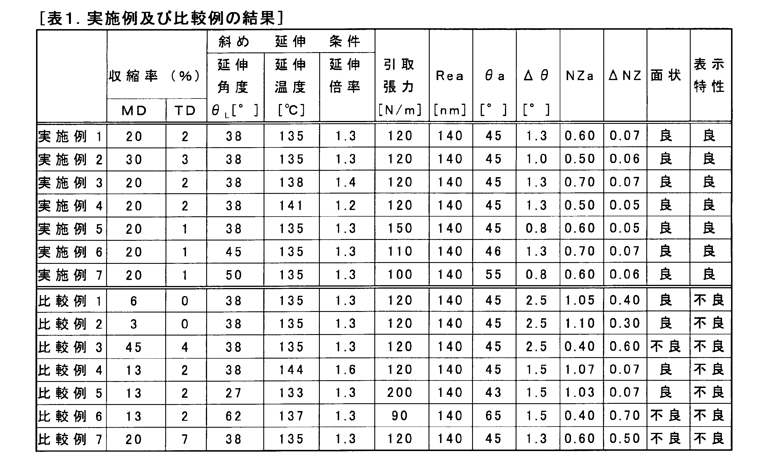
表1から分かるように、実施例1~7においては、1330mm幅の全体において、斜め方向に遅相軸を有し、0<NZ係数<1.00という特定範囲のNZ係数を有し、且つ、配向角θ及びNZ係数のバラツキが小さい延伸フィルムを得ている。また、実施例1~7において得られた延伸フィルムは、いずれも、延伸時におけるシワの発生が抑制されている。そして、これらの延伸フィルムを用いて製造した円偏光板を適用した表示装置においては、傾斜方向から見た場合における外光の反射が抑制されている。以上の結果から、本発明の製造方法により、円偏光板の製造に適した長尺の延伸フィルムを安定して製造できることが確認された。
11及び12 複層フィルム(D)のフィルム幅方向の端部
21 テンター延伸機の入口部において、相対している一組の把持具を結んだ直線
22 延伸が行われた後に出口側の直線部分に達した時、一組の把持具を結んだ直線
100 テンター延伸機
110L及び110R 把持具
120L及び120R レール
130 入口部
140 出口部
150 出口側の直線部分
160 出口部における延伸後の複層フィルム(D)の進行方向に垂直な方向
θi 繰出角度
θL 延伸角度
Claims (9)
- 熱可塑性樹脂からなる延伸前フィルム(A)、空気中における140℃60秒の条件下でのフィルム長手方向の収縮率が10%以上40%以下でありフィルム幅方向の収縮率が5%以下である収縮性フィルム(B)、並びに、前記延伸前フィルム(A)と前記収縮性フィルム(B)とを接着する接着層(C)を備える長尺の複層フィルム(D)を、1.5倍未満の延伸倍率で、前記複層フィルム(D)の幅方向に対して45°±15°の方向に延伸する工程と、
前記収縮性フィルム(B)及び前記接着層(C)を剥離する工程と、を含む、延伸フィルムの製造方法。 - 前記熱可塑樹脂が、脂環式ポリオレフィンを含む樹脂である、請求項1記載の延伸フィルムの製造方法。
- 前記収縮性フィルム(B)が、ポリエステルを含む原料フィルムを延伸することにより得られたものである、請求項1又は2に記載の延伸フィルムの製造方法。
- 前記複層フィルム(D)の延伸が、テンター延伸機を用いてテンター延伸法により行われるものである、請求項1~3のいずれかに記載の延伸フィルムの製造方法。
- 前記テンター延伸機の出口部における前記複層フィルム(D)の引取張力が、100N/mより大きく400N/m未満である、請求項4に記載の延伸フィルムの製造方法。
- 熱可塑性樹脂からなる長尺の延伸フィルムであって、前記延伸フィルムの、少なくとも1300mm幅の部分において、
フィルム長手方向に対する面内の配向角θの平均値θaが、40°<θa<80°であり、
前記配向角θの最大値θmaxと最小値θminとの差θmax-θminが、2°以下であり、
NZ係数の平均値NZaが、0<NZa<1.00であり、かつ、
前記NZ係数の最大値NZmaxと前記NZ係数の最小値NZminとの差NZmax-NZminが、0.10未満である、延伸フィルム。 - 前記NZ係数の平均値NZaが、0.20より大きく、0.8以下である、請求項6に記載の延伸フィルム。
- 請求項6又は7に記載の延伸フィルムを備える、円偏光板。
- 請求項8記載の円偏光板から切り出された円偏光フィルム片を備える、表示装置。
Priority Applications (4)
| Application Number | Priority Date | Filing Date | Title |
|---|---|---|---|
| JP2018503315A JP6806135B2 (ja) | 2016-02-29 | 2017-02-28 | 延伸フィルム、及び円偏光板 |
| CN201780009646.8A CN108603971B (zh) | 2016-02-29 | 2017-02-28 | 拉伸膜及其制造方法、圆偏振片以及显示装置 |
| US16/076,061 US20190152131A1 (en) | 2016-02-29 | 2017-02-28 | Stretched film, method for manufacturing same, circular polarization plate, and display device |
| KR1020187022793A KR102515374B1 (ko) | 2016-02-29 | 2017-02-28 | 연신 필름 및 그 제조 방법, 원 편광판, 그리고 표시 장치 |
Applications Claiming Priority (2)
| Application Number | Priority Date | Filing Date | Title |
|---|---|---|---|
| JP2016-037378 | 2016-02-29 | ||
| JP2016037378 | 2016-02-29 |
Publications (1)
| Publication Number | Publication Date |
|---|---|
| WO2017150495A1 true WO2017150495A1 (ja) | 2017-09-08 |
Family
ID=59743011
Family Applications (1)
| Application Number | Title | Priority Date | Filing Date |
|---|---|---|---|
| PCT/JP2017/007662 Ceased WO2017150495A1 (ja) | 2016-02-29 | 2017-02-28 | 延伸フィルム及びその製造方法、円偏光板、並びに表示装置 |
Country Status (5)
| Country | Link |
|---|---|
| US (1) | US20190152131A1 (ja) |
| JP (1) | JP6806135B2 (ja) |
| KR (1) | KR102515374B1 (ja) |
| CN (1) | CN108603971B (ja) |
| WO (1) | WO2017150495A1 (ja) |
Cited By (2)
| Publication number | Priority date | Publication date | Assignee | Title |
|---|---|---|---|---|
| JP2019133074A (ja) * | 2018-02-02 | 2019-08-08 | 日東電工株式会社 | 延伸フィルムの製造方法 |
| JPWO2021107108A1 (ja) * | 2019-11-29 | 2021-06-03 |
Families Citing this family (2)
| Publication number | Priority date | Publication date | Assignee | Title |
|---|---|---|---|---|
| KR102595566B1 (ko) * | 2018-10-31 | 2023-10-27 | 엘지디스플레이 주식회사 | 스트레쳐블 표시 장치 |
| JP7644787B2 (ja) * | 2023-02-17 | 2025-03-12 | 日東電工株式会社 | 延伸フィルムの製造方法 |
Citations (6)
| Publication number | Priority date | Publication date | Assignee | Title |
|---|---|---|---|---|
| JP2006072309A (ja) * | 2004-08-05 | 2006-03-16 | Nitto Denko Corp | 位相差フィルム、その製造方法、光学フィルム、画像表示装置、液晶パネル及び液晶表示装置 |
| JP2006091836A (ja) * | 2004-08-26 | 2006-04-06 | Nitto Denko Corp | 位相差フィルムおよびその製造方法、ならびに、該位相差フィルムを用いた光学フィルム、液晶パネルおよび液晶表示装置 |
| JP2007233198A (ja) * | 2006-03-02 | 2007-09-13 | Nippon Zeon Co Ltd | 延伸フィルムおよび延伸フィルムの製造方法 |
| JP2009078474A (ja) * | 2007-09-26 | 2009-04-16 | Nippon Zeon Co Ltd | 延伸フィルムの製造方法、延伸フィルム、偏光板、及び液晶表示装置 |
| JP2011039343A (ja) * | 2009-08-13 | 2011-02-24 | Nippon Zeon Co Ltd | 位相差板の製造方法、位相差板、および偏光板 |
| WO2015064645A1 (ja) * | 2013-10-30 | 2015-05-07 | 日本ゼオン株式会社 | 長尺の延伸フィルム及びその製造方法 |
Family Cites Families (3)
| Publication number | Priority date | Publication date | Assignee | Title |
|---|---|---|---|---|
| JP2818983B2 (ja) | 1990-10-24 | 1998-10-30 | 日東電工株式会社 | 複屈折性フィルムの製造方法 |
| TW397928B (en) * | 1993-12-22 | 2000-07-11 | Sumitomo Chemical Co | Process for prodoucing phase retarder film |
| CN101808804B (zh) * | 2007-09-26 | 2013-02-13 | 日本瑞翁株式会社 | 拉伸膜的制造方法、拉伸膜、偏振片、及液晶显示装置 |
-
2017
- 2017-02-28 KR KR1020187022793A patent/KR102515374B1/ko active Active
- 2017-02-28 JP JP2018503315A patent/JP6806135B2/ja active Active
- 2017-02-28 US US16/076,061 patent/US20190152131A1/en not_active Abandoned
- 2017-02-28 WO PCT/JP2017/007662 patent/WO2017150495A1/ja not_active Ceased
- 2017-02-28 CN CN201780009646.8A patent/CN108603971B/zh active Active
Patent Citations (6)
| Publication number | Priority date | Publication date | Assignee | Title |
|---|---|---|---|---|
| JP2006072309A (ja) * | 2004-08-05 | 2006-03-16 | Nitto Denko Corp | 位相差フィルム、その製造方法、光学フィルム、画像表示装置、液晶パネル及び液晶表示装置 |
| JP2006091836A (ja) * | 2004-08-26 | 2006-04-06 | Nitto Denko Corp | 位相差フィルムおよびその製造方法、ならびに、該位相差フィルムを用いた光学フィルム、液晶パネルおよび液晶表示装置 |
| JP2007233198A (ja) * | 2006-03-02 | 2007-09-13 | Nippon Zeon Co Ltd | 延伸フィルムおよび延伸フィルムの製造方法 |
| JP2009078474A (ja) * | 2007-09-26 | 2009-04-16 | Nippon Zeon Co Ltd | 延伸フィルムの製造方法、延伸フィルム、偏光板、及び液晶表示装置 |
| JP2011039343A (ja) * | 2009-08-13 | 2011-02-24 | Nippon Zeon Co Ltd | 位相差板の製造方法、位相差板、および偏光板 |
| WO2015064645A1 (ja) * | 2013-10-30 | 2015-05-07 | 日本ゼオン株式会社 | 長尺の延伸フィルム及びその製造方法 |
Cited By (9)
| Publication number | Priority date | Publication date | Assignee | Title |
|---|---|---|---|---|
| JP2019133074A (ja) * | 2018-02-02 | 2019-08-08 | 日東電工株式会社 | 延伸フィルムの製造方法 |
| WO2019150897A1 (ja) * | 2018-02-02 | 2019-08-08 | 日東電工株式会社 | 延伸フィルムの製造方法 |
| JP7016269B2 (ja) | 2018-02-02 | 2022-02-04 | 日東電工株式会社 | 延伸フィルムの製造方法 |
| JPWO2021107108A1 (ja) * | 2019-11-29 | 2021-06-03 | ||
| WO2021107108A1 (ja) * | 2019-11-29 | 2021-06-03 | 日本ゼオン株式会社 | 位相差フィルム及びその製造方法 |
| CN114730039A (zh) * | 2019-11-29 | 2022-07-08 | 日本瑞翁株式会社 | 相位差膜及其制造方法 |
| CN114730039B (zh) * | 2019-11-29 | 2024-04-23 | 日本瑞翁株式会社 | 相位差膜及其制造方法 |
| JP7567808B2 (ja) | 2019-11-29 | 2024-10-16 | 日本ゼオン株式会社 | 位相差フィルムの製造方法 |
| JP2024174197A (ja) * | 2019-11-29 | 2024-12-13 | 日本ゼオン株式会社 | 位相差フィルム |
Also Published As
| Publication number | Publication date |
|---|---|
| CN108603971B (zh) | 2021-07-13 |
| JP6806135B2 (ja) | 2021-01-06 |
| KR102515374B1 (ko) | 2023-03-28 |
| JPWO2017150495A1 (ja) | 2018-12-20 |
| US20190152131A1 (en) | 2019-05-23 |
| CN108603971A (zh) | 2018-09-28 |
| KR20180118621A (ko) | 2018-10-31 |
Similar Documents
| Publication | Publication Date | Title |
|---|---|---|
| JP4488124B2 (ja) | 延伸フィルムの製造方法、延伸フィルム、偏光板、及び液晶表示装置 | |
| JP4557188B2 (ja) | 長尺の延伸フィルムおよびその製造方法並びに用途 | |
| JP6702193B2 (ja) | 長尺の円偏光板、長尺の広帯域λ/4板、並びに、長尺の広帯域λ/4板、有機エレクトロルミネッセンス表示装置、及び、液晶表示装置の、製造方法 | |
| CN101341016B (zh) | 长的斜向延伸膜的制造方法 | |
| JP5151356B2 (ja) | 延伸フィルムの製造方法、延伸フィルム、偏光板、及び液晶表示装置 | |
| JP6999059B2 (ja) | 位相差層付偏光板およびそれを用いた画像表示装置 | |
| JP7355582B2 (ja) | 位相差層付偏光板およびそれを用いた画像表示装置 | |
| JPWO2017170346A1 (ja) | 円偏光板及び画像表示装置 | |
| JP6806135B2 (ja) | 延伸フィルム、及び円偏光板 | |
| JP2008238514A (ja) | 延伸フィルムの製造方法、延伸フィルム、偏光板及び液晶表示装置 | |
| JP5017835B2 (ja) | 延伸フィルムおよび延伸フィルムの製造方法 | |
| JP5553067B2 (ja) | 長尺の延伸フィルム、長尺の積層フィルム、偏光板及び液晶表示装置 | |
| JP2016212171A (ja) | 光学積層体、円偏光板及び有機エレクトロルミネッセンス表示装置 | |
| JP5098296B2 (ja) | 長尺の延伸フィルムの製造方法 | |
| JP5370527B2 (ja) | 延伸フィルムおよび延伸フィルムの製造方法 | |
| JP2009214441A (ja) | 延伸フィルムの製造方法、延伸フィルム、偏光板、及び液晶表示装置 | |
| JP6825654B2 (ja) | 円偏光板の製造方法及び光学積層体の製造方法 | |
| JP2019055603A (ja) | 斜め延伸フィルム及びその製造方法 | |
| JP2009214343A (ja) | 延伸フィルムの製造方法 | |
| JP2016179650A (ja) | 斜め延伸フィルム及びその製造方法 |
Legal Events
| Date | Code | Title | Description |
|---|---|---|---|
| ENP | Entry into the national phase |
Ref document number: 2018503315 Country of ref document: JP Kind code of ref document: A |
|
| ENP | Entry into the national phase |
Ref document number: 20187022793 Country of ref document: KR Kind code of ref document: A |
|
| NENP | Non-entry into the national phase |
Ref country code: DE |
|
| 121 | Ep: the epo has been informed by wipo that ep was designated in this application |
Ref document number: 17759961 Country of ref document: EP Kind code of ref document: A1 |
|
| 122 | Ep: pct application non-entry in european phase |
Ref document number: 17759961 Country of ref document: EP Kind code of ref document: A1 |