WO2017150062A1 - 分光測定装置 - Google Patents
分光測定装置 Download PDFInfo
- Publication number
- WO2017150062A1 WO2017150062A1 PCT/JP2017/003660 JP2017003660W WO2017150062A1 WO 2017150062 A1 WO2017150062 A1 WO 2017150062A1 JP 2017003660 W JP2017003660 W JP 2017003660W WO 2017150062 A1 WO2017150062 A1 WO 2017150062A1
- Authority
- WO
- WIPO (PCT)
- Prior art keywords
- light
- axis direction
- optical system
- measured
- intensity
- Prior art date
- Legal status (The legal status is an assumption and is not a legal conclusion. Google has not performed a legal analysis and makes no representation as to the accuracy of the status listed.)
- Ceased
Links
Images




Classifications
-
- G—PHYSICS
- G01—MEASURING; TESTING
- G01J—MEASUREMENT OF INTENSITY, VELOCITY, SPECTRAL CONTENT, POLARISATION, PHASE OR PULSE CHARACTERISTICS OF INFRARED, VISIBLE OR ULTRAVIOLET LIGHT; COLORIMETRY; RADIATION PYROMETRY
- G01J3/00—Spectrometry; Spectrophotometry; Monochromators; Measuring colours
- G01J3/28—Investigating the spectrum
- G01J3/45—Interferometric spectrometry
-
- G—PHYSICS
- G01—MEASURING; TESTING
- G01N—INVESTIGATING OR ANALYSING MATERIALS BY DETERMINING THEIR CHEMICAL OR PHYSICAL PROPERTIES
- G01N21/00—Investigating or analysing materials by the use of optical means, i.e. using sub-millimetre waves, infrared, visible or ultraviolet light
- G01N21/17—Systems in which incident light is modified in accordance with the properties of the material investigated
- G01N21/25—Colour; Spectral properties, i.e. comparison of effect of material on the light at two or more different wavelengths or wavelength bands
- G01N21/27—Colour; Spectral properties, i.e. comparison of effect of material on the light at two or more different wavelengths or wavelength bands using photo-electric detection ; circuits for computing concentration
Definitions
- the present invention relates to a spectroscopic measurement apparatus that qualitatively or quantitatively measures a measurement target by using spectral characteristics of the measurement target.
- One of the methods for measuring biological components such as glucose (blood glucose) and cholesterol contained in blood is light emitted from biological components inside the subject site when the subject site is irradiated with light.
- the intensity of the interference light between the light reflected by the movable mirror and the light reflected by the fixed mirror changes to form a so-called interferogram.
- a spectral characteristic (spectrum) of the internally scattered light is acquired by Fourier transforming the interferogram.
- the light quantity distribution of the interference light on the imaging surface is affected by the difference in diffraction angle due to the texture (surface condition) of the region to be examined.
- the light intensity distribution of the internally scattered light on the imaging surface varies depending on the refractive index distribution of the region to be examined and the optical texture, so this light intensity distribution is the amount of interference light that depends on the concentration of biological components. It is superimposed on the distribution, and the concentration of the biological component cannot be measured accurately.
- an image of the object plane is once formed on an image plane optically conjugate with the object plane by a conjugate imaging optical system, and the object light beam is spatialized by an amplitude type diffraction grating placed on the conjugate image plane.
- Patent Document 2 Non-Patent Document 1
- the amplitude type diffraction grating is an arrangement in which a light transmitting portion and a light shielding portion are alternately arranged in the light collecting axis direction (image forming line direction).
- the length in the axial direction and the interference axis direction (the direction perpendicular to the condensing axis direction) (vertical and horizontal lengths of the translucent portion) is very small, from several tens ⁇ m to several hundreds ⁇ m, and is also called a multiple slit.
- a spectroscopic measurement device on an unmanned aerial vehicle called a drone, and to measure components contained in the object to be measured, such as components contained in plankton in the sea and leaves of forest trees.
- the sunlight incident on the sea surface and the leaves of the trees enters the sea and the inside of the leaves, is reflected by the plankton in the sea and the components inside the leaves, and then the light emitted to the outside (internally scattered light) Measured with a spectrometer.
- the near-infrared light having excellent skin permeability is irradiated to the test site. For this reason, much irradiation light can be made to enter the inside of a test part.
- the sunlight incident on the surface of the sea or the leaves of trees most of the sunlight is reflected on the surface of the sea or leaves, and less light enters the sea or inside the leaves of the trees. For this reason, high-intensity light (surface reflected light) reflected from the surface of the sea or leaves is superimposed on the internally scattered light that should be received by the spectroscopic measurement device, and the internal components of plankton and leaves in the sea are superposed. The spectroscopic measurement cannot be performed accurately.
- the problem to be solved by the present invention is to acquire a clear interferogram and high-accuracy spectral characteristics of the internal components of the object to be measured while suppressing the influence of light reflected from the surface of the object to be measured. .
- the spectroscopic measurement device which has been made to solve the above problems, a) a splitting optical system that splits light from the object to be measured into two in a predetermined first axis direction to form first measuring light and second measuring light; b) Optical path length difference providing an optical path length difference that continuously varies along the second axis direction, which is a direction orthogonal to the first axis direction, between the first measurement light and the second measurement light. Means, c) Condensing the first measurement light and the second measurement light to which the continuously changing optical path length difference is provided in the first axis direction to form linear interference light on the image plane.
- An image optical system d) an interference light detection unit that detects the intensity of the interference light, and includes a plurality of pixels arranged at a predetermined period in the second axis direction on the imaging plane; e) Processing for obtaining an interferogram of a component included in the object to be measured based on the light intensity of the interference light detected by the interference light detection unit, and acquiring a spectrum by Fourier transforming the interferogram And f) a conjugate plane imaging optical system having a conjugate plane in common with the divided optical system, disposed between the object to be measured and the divided optical system; g) an amplitude diffraction grating having a plurality of light-transmitting portions and a plurality of light-shielding portions arranged in the conjugate plane and periodically arranged in the first axis direction; With An optical element in which at least some of the plurality of light transmitting parts pass light emitted from the inside of the measurement object while attenuating polarized light derived from the surface reflected light reflected on the
- the first axis direction corresponds to a so-called condensing axis direction
- the second axis direction corresponds to an interference axis direction
- the spectroscopic measurement device In the spectroscopic measurement device, light incident on the surface of the object to be measured enters the inside of the object to be measured, is reflected by components contained therein, and is emitted to the outside of the object to be measured (internal Scattered light) passes through the transmission part of the amplitude type diffraction grating and is given a spatial periodic change. Thereafter, the internally scattered light is divided into the first measurement light and the second measurement light by the splitting optical system, and an optical path length difference that continuously changes between the first measurement light and the second measurement light by the optical path length difference providing means. Is granted.
- the interference light of the first measurement light and the second measurement light is formed on the imaging surface by the imaging optical system, and the intensity of the interference light is detected by the interference light detection unit arranged on the imaging surface, A spectrum is acquired by the processing unit.
- the translucent portion of the amplitude type diffraction grating attenuates polarized light derived from the surface reflected light reflected by the surface of the object to be measured, and the inside emitted from the object to be measured Since the optical element is configured to allow the scattered light to pass therethrough, it is possible to reduce the ratio of the surface reflected light of the object to be measured that occupies the light toward the split optical system.
- the optical element includes a first linearly polarizing plate disposed so that a transmission axis direction is the first axial direction, and a second linearly polarized light disposed such that the transmission axis direction is the second axial direction.
- a first linearly polarizing plate disposed so that a transmission axis direction is the first axial direction
- a second linearly polarized light disposed such that the transmission axis direction is the second axial direction.
- One or more types of linearly polarizing plates selected from a plate and a third linearly polarizing plate arranged so that the direction of the transmission axis is different from both the first and second axis directions Can be used.
- the surface reflected light contains almost P-polarized light component.
- the S polarization component becomes dominant.
- the P-polarized light component is a linearly polarized light component whose electric field vibration direction is perpendicular to the incident surface (a surface including incident light and reflected light), and the S-polarized light component is vertical polarized light whose electric field vibration direction is parallel to the incident surface. Ingredients.
- the internally scattered light emitted from the inside of the object to be measured is almost maintained in a non-polarized state.
- the surface reflected light is incident so that the transmission axis of the linearly polarizing plate is perpendicular to the incident surface and the incident angle is in a predetermined angle range. If the spectroscopic measurement device is installed in any direction, most of the polarized light derived from the surface reflected light (that is, the S-polarized light component) cannot pass through the light transmitting portion composed of the linearly polarizing plate, so that the surface reflected light is attenuated. be able to.
- the plurality of light transmitting portions are arranged such that a transmission axis direction is the first axis direction and a transmission axis direction is the second axis.
- a second linearly polarizing plate arranged to be in a direction, or the plurality of translucent portions are arranged so that a direction of a transmission axis is in the first axis direction.
- the direction of the transmission axis is different from either the first axial direction or the second axial direction with any one of the second linearly polarizing plates arranged so that the direction of the plate and the transmission axis is the second axial direction. It is preferable to comprise from the 3rd linearly-polarizing plate arrange
- a part of the translucent part is derived from polarized light derived from surface reflected light and internally scattered light. It is possible to allow both of the polarized light to pass through and the remaining light transmitting part to pass only the polarized light derived from the internally scattered light and not allow the polarized light derived from the surface reflected light to pass.
- a part of the linearly polarizing plate constituting the light transmitting part passes the P-polarized component of the internally scattered light, and the remaining linearly polarizing plate passes the S-polarized component of the surface reflected light and the S-polarized component of the internally scattered light.
- the intensity of the P-polarized light component detected by some pixels of the interference light detector the intensity of the surface reflected light from the light intensity of the S-polarized light component detected by the remaining pixels, The intensity of the scattered light can be obtained, and the intensity (spectral characteristic) of each surface reflected light for each wavelength and the intensity (spectral characteristic) for each wavelength of the internal scattered light can be obtained.
- the spectral characteristic of the surface reflected light reflects the light incident on the object to be measured, that is, the light source color.
- the spectral characteristic of the internal scattered light reflects the spectral characteristic of the reflected light of the internal component of the object to be measured (in other words, the spectral characteristic of the absorbed light). Therefore, by performing light source color correction (background correction) using the intensity of the surface reflected light, it is possible to obtain highly accurate spectral characteristics of the internal components.
- the spectroscopic measurement method according to the present invention made to solve the above problems is a) The light from the object to be measured is split into two in a predetermined first axis direction by a splitting optical system to form first measuring light and second measuring light; b) An optical path length difference that continuously changes along a second axis direction that is a direction orthogonal to the first axis direction is provided between the first measurement light and the second measurement light, c) The first measurement light and the second measurement light, to which a continuously changing optical path length difference is given, are condensed in the first axis direction by an imaging optical system and linearly formed on the imaging surface.
- Form interference light d) detecting the intensity of the interference light using an interference light detector having a plurality of pixels arranged at a predetermined period in the second axis direction on the imaging plane; e) Spectroscopy that obtains a spectrum by obtaining an interferogram of a component contained in the object to be measured based on the light intensity of the interference light detected by the interference light detection unit and Fourier-transforming the interferogram
- a conjugate plane imaging optical system having a conjugate plane common to the divided optical system is disposed between the object to be measured and the divided optical system, and is periodically arranged in the first axis direction on the conjugate plane.
- An amplitude type diffraction grating having a plurality of light transmitting parts and a plurality of light shielding parts is arranged, and at least a part of the light transmitting parts is attenuated by polarization reflected from the surface reflected light reflected from the surface of the object to be measured. And an optical element that allows light emitted from the inside of the object to be measured to pass therethrough.
- the amplitude type diffraction grating is disposed on the common conjugate plane of the split optical system and the conjugate plane imaging optical system, and the light transmitting portion of the amplitude type diffraction grating is reflected by the surface of the object to be measured. Since the optical element that passes the light emitted from the inside of the object to be measured is attenuated while the polarized light derived from the surface reflected light is attenuated, the difference in the texture of the object to be measured is the light quantity distribution of the internally scattered light on the imaging surface. A clear interferogram and high-precision spectral characteristics of the internal components of the object to be measured can be acquired while suppressing the influence on the measurement object.
- FIG. 1 is a perspective view showing an overall configuration of a spectrometer according to a first embodiment of the present invention.
- the top view of a spectrometer. The side view of a spectrometer.
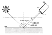
- the schematic diagram explaining the measurement principle when measuring on the conditions which scattered surface reflected light injects into a spectrometer.
- the figure for demonstrating the relationship between the S polarization component and P polarization component of surface reflected light and internal scattering light The figure which shows the result measured using the spectrometer which concerns on this embodiment.
- the schematic diagram explaining the measurement principle when measuring on the conditions in which surface reflected light directly injects into a spectrometer.
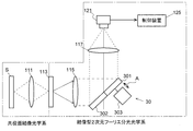
- the perspective view which shows the whole structure of the spectrometer which concerns on 2nd Embodiment of this invention.
- the spectroscopic measurement apparatus 100 includes a conjugate plane imaging optical system and an imaging type one-dimensional Fourier spectroscopy optical system.
- the conjugate plane imaging optical system an image of a measurement target (object plane) is optically coupled with an object plane using a lens 11 such as an imaging lens, a wide-angle lens, or a micro objective lens in accordance with a viewing field range and magnification that are observation conditions.
- a lens 11 such as an imaging lens, a wide-angle lens, or a micro objective lens in accordance with a viewing field range and magnification that are observation conditions.
- This conjugate plane becomes the object plane of the imaging type one-dimensional Fourier spectroscopic optical system, and the multiple slits 13 are arranged on the conjugate plane.
- the multiple slits 13 correspond to the amplitude type diffraction grating of the present invention.
- the multiple slit 13 has a plurality of light transmitting portions 131 periodically arranged in a predetermined direction.
- a portion between the light transmitting portion 131 and the light transmitting portion 131 serves as a light shielding portion 132.
- the direction in which the light transmitting portions 131 of the multiple slits 13 are arranged corresponds to the first axis direction of the present invention.
- the width of the translucent part 131 is set to be approximately the same as the pixel pitch (pixel size) in the first axis direction of the two-dimensional light receiving array device 21 described later.
- the optical element 131A includes a first linear polarizing plate in which the direction of the transmission axis coincides with the first axis direction, a second linear polarizing plate in which the direction of the transmission axis coincides with the second axial direction, and the direction of the transmission axis is the first.
- One or more types of linear polarizing plates selected from the third linear polarizing plates in directions different from the axis and the second axis are used. Which linear polarizing plate is used depends on the type of light incident on the object to be measured (polarized light or non-polarized light), and at what angle to the surface of the object to be measured. Decide whether to install
- the imaging type one-dimensional Fourier spectroscopic optical system is an infinitely corrected imaging optical system composed of an objective lens 15 and an imaging lens 17, and a phase shifter 19 is connected in the vicinity of the optical Fourier transform plane, and the imaging lens 17 is connected.
- Two-dimensional light receiving array devices 21 are respectively installed on the image plane.
- the imaging lens 17 corresponds to the imaging optical system of the present invention
- the two-dimensional light receiving array device 21 corresponds to the interference light detection unit of the present invention.
- the phase shifter 19 includes a first transmission part 191 and a second transmission part 192, which are semicircular transmission type optical members, and has a substantially disk-like configuration as a whole.
- the first transmission unit 191 and the second transmission unit 192 are configured by an optical member that can transmit the wavelength band of light measured by this apparatus.
- the first transmission part 191 is made of an optical member having a constant thickness and having an incident surface and an output surface that are parallel to each other.
- the second transmissive part 192 is a wedge-shaped optical member having an incident surface that is inclined with respect to the incident surface of the first transmissive part 191 and an output surface that is on the same plane as the output surface of the first transmissive part 191. Become.
- the thickness of the second transmission part 192 gradually decreases from one side to the other side (in FIG. 1, from the front side to the back side), so that the incident surface changes from one side to the other side. It inclines toward the imaging lens 17 side.
- the imaging lens 17 is a plano-convex cylindrical lens.
- the imaging lens 17 is formed of a cylindrical convex surface centering on an axis parallel to the second axis, the surface on the phase shifter 19 side projecting toward the phase shifter 19, and the surface on the two-dimensional light receiving array device 21 side. Consists of a plane parallel to the exit surface of the phase shifter 19.
- the objective lens 15 and the phase shifter 19 constitute the split optical system of the present invention, and the phase shifter 19 constitutes the optical path length difference providing means of the present invention.
- the direction in which the thickness of the second transmission part 192 changes corresponds to the second axial direction of the present invention, and is orthogonal to the first axial direction described above.
- the first axis is represented as a vertical axis
- the second axis is represented as a horizontal axis, but it may be reversed or an axis other than the horizontal axis or the vertical axis may be used. In short, it suffices if the first axis direction and the second axis direction are orthogonal to each other.
- the two-dimensional light receiving array device 21 is composed of a two-dimensional CCD camera having a plurality of pixels arranged at a predetermined pitch in the first axis direction and the second axis direction. Note that the inclination angle of the incident surface of the second transmission unit 192 depends on the phase shift amount determined by the wave number resolution and the sampling interval in the second axis direction of the pixels of the two-dimensional light receiving array device 21 (the pitch of the pixels arranged in the second axis direction). ), But there is no problem even if it deviates slightly.
- the spectroscopic measurement apparatus 100 measures both the spectral characteristics of light (internally scattered light) emitted from the inside of the object to be measured and the spectral characteristics of light (surface reflected light) emitted from the surface of the object to be measured.
- the present invention aims to measure the spectral characteristics of the internally scattered light and quantitatively and qualitatively analyze the components contained in the object to be measured. A method for obtaining the characteristics will be described. That is, the measurement target of the spectrometer 100 according to the present embodiment is an internal component of the object to be measured.
- the reflectivity is determined based on the refractive index difference at the interface, as is known from the Fresnel reflection law. It is known that the refractive index of biological systems such as plankton existing in the sea is slightly larger than the refractive index of water (1.33) (for example, refractive index: 1.38). Therefore, the difference in refractive index between plankton and water is very small compared to the difference in refractive index at the sea surface (atmospheric refractive index: 1.0, water refractive index: 1.33). For this reason, the reflectance at the sea surface (surface reflectance) is several hundred times greater than the internal scattering reflectance.
- the spectroscopic measurement apparatus 100 is arranged so that the scattered surface reflected light is incident on the spectroscopic measurement apparatus 100.
- the scattered surface reflected light is simply referred to as surface reflected light.
- the light receiving axis L1 (axis extending in a direction orthogonal to the first axis and the second axis) of the spectroscopic measurement apparatus 100 and a horizontal plane in a state where the back is directed to the sun.
- the spectroscopic measurement apparatus 100 is installed so that the angle (the depression angle) is ⁇ [deg.]. Further, the spectroscopic measurement apparatus 100 is installed so as to be in the horizontal direction of either the first axis direction or the second axis direction.
- the multiple slits 13 are arranged on the conjugate plane, and a linear polarizing plate is fitted in the light transmitting part 131 of the multiple slits 13.
- a linear polarizing plate in which the direction of the transmission axis is the first axial direction and a linear polarizing plate in which the direction of the transmission axis is the second axial direction are used as the linear polarizing plates.
- the S-polarized light derived from the surface reflected light and the internally scattered light passes through only one of these two types of linearly polarizing plates and does not pass through the other.
- the P-polarized light derived from the surface reflected light and the internally scattered light passes only through the other of the two types of linearly polarizing plates, and does not pass through the other.
- Non-polarized light such as sunlight can be decomposed into a P-polarized component and an S-polarized component.
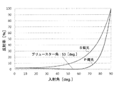
- FIG. 6 shows the relationship between the reflectance and the incident angle of the P-polarized component and the S-polarized component when such non-polarized light is incident on the surface of the object to be measured at a predetermined angle.
- FIG. 6 is a graph showing the reflectance for each incident angle of P-polarized light and S-polarized light at the interface of water (refractive index 1.33) and air (refractive index 1.00).
- the reflectance of each polarized light was obtained from an equation according to the Fresnel reflection law. As can be seen from FIG. 6, the reflectance of the S-polarized component is higher than the reflectance of the P-polarized component throughout.
- the incident angle is less than about 70 [deg.]
- the reflectance of the P-polarized component becomes very low, and becomes 0% at the Brewster angle.
- the Brewster angle at the interface between water and air is 53 [deg.].
- Brewster's angle refers to the direction of vibration of an electric field when light is incident on the interface between two substances with different refractive indices from one substance (incident side medium) to the other substance (transmission side medium).
- the linearly polarized light component (P-polarized light) parallel to the surface (the surface including incident light and reflected light) is incident on the inside of the material, and only the linearly polarized light component (S-polarized light) whose electric field vibration direction is perpendicular to the incident surface is reflected.
- the light transmitting portions 131 and the light shielding portions 132 are alternately arranged in the multiple slits 13, the light that has passed through the light transmitting portions 131 is given a spatial periodicity, and is then divided into a split optical system and a plano-convex cylindrical surface.
- the light enters the two-dimensional light receiving array device 21 through the lens 17.
- the light incident on the objective lens 15 constituting the split optical system is split into two in the first axis direction by the phase shifter 19 and is emitted as the first measurement light and the second measurement light.
- the first transmission part 191 constituting the phase shifter 19 is composed of an optical member having a constant thickness with the incident surface and the output surface parallel, and the second transmission part 192 has a thickness from one side to the other side. Since the optical member gradually decreases toward the first direction, a continuous optical path length difference is given between the first measurement light that has passed through the first transmission part 191 and the second measurement light that has passed through the second transmission part 192. .
- the first measurement light and the second measurement light are condensed in the first axis direction by the plano-convex cylindrical lens 17 to form interference light on the imaging plane.
- a large number of pixels constituting the two-dimensional light receiving array device 21 are arranged on the imaging plane, and the intensity of the interference light is detected by these pixels.
- the intensity of the interference light formed by the light transmitted through the corresponding light transmitting portions 131 is detected.
- part of the plurality of translucent portions 131 passes the S-polarized component of the surface reflected light and the S-polarized component of the internally scattered light, and the rest passes only the P-polarized component of the internally scattered light. Therefore, in some pixels, the intensity of the interference light caused by the superposition of the S-polarized component of the surface reflected light and the S-polarized component of the internally scattered light is detected, and in the remaining pixels, the interference light of the P-polarized component of the internally scattered light is detected. Intensity is detected.
- the detection signal of the two-dimensional light receiving array device 21 is input to a control device 25 composed of a personal computer or the like, a plankton interferogram is obtained by a predetermined calculation process, and a spectrum (spectral characteristics) is obtained by Fourier-transforming the interferogram. ) Is obtained. Therefore, in the present embodiment, the control device 25 corresponds to the processing unit of the present invention.
- the control device 25 determines the intensity of the interference light formed by superimposing the S-polarized component of the surface reflected light and the S-polarized component of the internally scattered light, and the interference light formed by the P-polarized component of the internally scattered light.
- the amount of surface reflected light and the amount of internally scattered light are obtained based on the intensity of the light, and the interferogram and spectrum of the surface reflected light and the internally scattered light are obtained using these.
- FIG. 8A shows an example of an interferogram and spectrum of surface reflected light
- FIG. 8B shows an example of an interferogram and spectrum of internally scattered light.
- the spectrum of the internal scattered light is corrected using the spectrum of the surface reflected light, and the spectral characteristics of the internal component (plankton) are obtained.
- the spectral characteristics of the internal component planekton
- the amount of light having a wavelength ⁇ is I 0 ( ⁇ )
- the surface reflectance (spectral reflectance) of the light having a wavelength ⁇ incident on the sea surface is r 1 ( ⁇ ). If the reflectance (spectral reflectance) due to the internal component of light of wavelength ⁇ is r 2 ( ⁇ ), the surface reflected light amount I 1 ( ⁇ ) of wavelength ⁇ and the internal scattered light amount I 2 ( ⁇ ) of wavelength ⁇ are It is expressed by a formula.
- the reflectances r 1 ( ⁇ ) and r 2 ( ⁇ ) are represented by the sum of the reflectances of the S-polarized component and the P-polarized component, respectively, as shown below.
- r 1 ( ⁇ ) r 1p ( ⁇ ) + r 1s ( ⁇ ) (3)
- r 2 ( ⁇ ) r 2p ( ⁇ ) + r 2s ( ⁇ ) (4)
- the light amounts Ip ( ⁇ ) and Is ( ⁇ ) of the P-polarized component and the S-polarized component of the light of wavelength ⁇ detected by the two-dimensional light receiving array device 21 are expressed by the following equations from equations (1) to (4). expressed.
- Ip ( ⁇ ) r 1p ( ⁇ ) ⁇ I 0 ( ⁇ ) + r 2p ( ⁇ ) ⁇ (1 ⁇ r 1p ( ⁇ ) ⁇ r 1s ( ⁇ )) ⁇ I 0 ( ⁇ ) (5)
- Is ( ⁇ ) r 1s ( ⁇ ) ⁇ I 0 ( ⁇ ) + r 2s ( ⁇ ) ⁇ (1 ⁇ r 1p ( ⁇ ) ⁇ r 1s ( ⁇ )) ⁇ I 0 ( ⁇ ) (6)
- the spectral reflectance r 2 ( ⁇ ) of the internally scattered light is expressed by the following equation.
- r 2 ( ⁇ ) [2r 1s ( ⁇ ) / (1 ⁇ r 1s ( ⁇ ))] ⁇ (Ip ( ⁇ ) / (Is ( ⁇ ) ⁇ Ip ( ⁇ )) (13)
- the value of the reflectance r 1s ( ⁇ ) of the S-polarized component of the surface scattered light can be estimated from the incident angle (90- ⁇ [deg.]) Of the surface reflected light incident on the spectrometer 100 (FIG. 6). reference). Further, the values of Ip ( ⁇ ) and Is ( ⁇ ) are obtained from the detection result of the two-dimensional light receiving array device 21.
- Equation (13) the spectral reflectance r 2 ( ⁇ ) of the internally scattered light can be obtained, and the spectral absorptance of the internal component can be obtained from this spectral reflectance r 2 ( ⁇ ). (1-r 2 ( ⁇ )) can be obtained. Therefore, the spectral characteristics of the internal component can be obtained using the spectral absorptance of the internal component.
- the spectroscopic measurement device 100 has a light receiving axis L1 (axis extending in a direction perpendicular to the first axis and the second axis) and a horizontal plane. It is installed so that the angle (the depression angle) is ⁇ [deg.].
- the spectroscopic measurement apparatus 100 is installed so as to be in the horizontal direction of either the first axis direction or the second axis direction. And it measures in the time slot
- zone when the altitude (phi) of sunlight becomes 90-53 37 [deg.].
- the lens 11 of the spectroscopic measurement apparatus 100 receives direct surface reflected light having an incident surface (a surface including incident light and reflected light) perpendicular to the sea surface and a reflection angle of 53 [deg.].
- the internally scattered light emitted from the sea enters the lens 11 of the spectroscopic measurement device 100 in the same direction as the surface reflected light.
- These direct surface reflected light and internal scattered light are condensed by a lens 11 on a common conjugate surface with the splitting optical system, passed through a multiple slit 13, an objective lens 15, a phase shifter 19, and a plano-convex cylindrical lens 17 to form a two-dimensional light receiving array.
- a spectrum is obtained by a predetermined calculation process in the control device 25.
- the sea surface is assumed to be a horizontal flat surface, but in reality, the sea surface is composed of inclined surfaces in various directions. Therefore, even in a time zone where the altitude of sunlight is 37 [deg.], The incident angle (reflection angle) of the surface reflected light reflected by the sea surface varies. Therefore, even when the spectroscopic measurement apparatus 100 is installed at a depression angle other than the angle ⁇ (37 [deg.]) Described above, the surface reflected light and the internal scattered light can be taken into the spectroscopic measurement apparatus 100.
- the reflected light and the internally scattered light can be transmitted to the spectrometer 100 by setting the depression angle of the spectrometer 100 to an appropriate value. Can be captured. In such a case, the surface reflected light becomes random polarized light including P-polarized light and S-polarized light, but the spectral characteristics of the internal components can be obtained by using the above-described calculation formula.
- the spectroscopic measurement apparatus 200 is different from the first embodiment in that the spectroscopic optical system is composed of an imaging type two-dimensional Fourier spectroscopic optical system. That is, the spectroscopic measurement apparatus 200 includes a conjugate plane imaging optical system, a multiple slit 113, and an imaging type two-dimensional Fourier spectroscopy optical system.
- the imaging type two-dimensional Fourier spectroscopic optical system includes an objective lens 115, a reflection type phase shifter 30, an imaging lens 117, a detection unit 121, and a control device 125.
- the detection unit 121 is constituted by a CCD camera, for example.
- the conjugate plane imaging optical system includes a lens 111 disposed between the multiple slit 113 and the object S to be measured.
- the conjugate plane imaging optical system and the objective lens 115 have a common conjugate plane, and multiple slits 113 are arranged on the common conjugate plane.
- the light incident on the movable mirror part 301 and the fixed mirror part 302 of the phase shifter 30 through the multiple slits 113 and the objective lens 115 is reflected by the reflecting surfaces of these two mirror parts, and then the imaging lens.
- the light passes through 117 and is collected and interferes with the light receiving surface of the detection unit 121.
- the interference light intensity received by the detection unit 121 is input to the control device 125 and subjected to Fourier transform, and then spectral characteristics are acquired. Even in such a configuration, the same operations and effects as those of the first embodiment described above can be obtained.
- All the light transmitting portions 131 of the multiple slits 13 may be configured by optical elements that block the passage of the polarization component derived from the surface reflected light of the object to be measured and transmit the polarization component derived from the internally scattered light.
- all the light transmitting parts are configured by linearly polarizing plates that transmit the P-polarized component and do not transmit the S-polarized component.
- the surface reflected light can be removed from the interference light detected by the interference light detector.
- the background correction of the internal scattered light can be performed using this information by acquiring in advance information on the intensity and spectral characteristics of the surface reflected light using a spectrophotometer or the like. .
Landscapes
- Physics & Mathematics (AREA)
- Spectroscopy & Molecular Physics (AREA)
- General Physics & Mathematics (AREA)
- Engineering & Computer Science (AREA)
- Mathematical Physics (AREA)
- Theoretical Computer Science (AREA)
- Health & Medical Sciences (AREA)
- Life Sciences & Earth Sciences (AREA)
- Chemical & Material Sciences (AREA)
- Analytical Chemistry (AREA)
- Biochemistry (AREA)
- General Health & Medical Sciences (AREA)
- Immunology (AREA)
- Pathology (AREA)
- Investigating Or Analysing Materials By Optical Means (AREA)
- Spectrometry And Color Measurement (AREA)
Applications Claiming Priority (2)
| Application Number | Priority Date | Filing Date | Title |
|---|---|---|---|
| JP2016-040357 | 2016-03-02 | ||
| JP2016040357A JP6744005B2 (ja) | 2016-03-02 | 2016-03-02 | 分光測定装置 |
Publications (1)
| Publication Number | Publication Date |
|---|---|
| WO2017150062A1 true WO2017150062A1 (ja) | 2017-09-08 |
Family
ID=59743794
Family Applications (1)
| Application Number | Title | Priority Date | Filing Date |
|---|---|---|---|
| PCT/JP2017/003660 Ceased WO2017150062A1 (ja) | 2016-03-02 | 2017-02-01 | 分光測定装置 |
Country Status (2)
| Country | Link |
|---|---|
| JP (1) | JP6744005B2 (https=) |
| WO (1) | WO2017150062A1 (https=) |
Cited By (2)
| Publication number | Priority date | Publication date | Assignee | Title |
|---|---|---|---|---|
| US20170299432A1 (en) * | 2016-04-15 | 2017-10-19 | Canon Kabushiki Kaisha | Spectroscopic data processing apparatus, image capturing apparatus, spectroscopic data processing method, and storage medium for storing spectroscopic data processing program |
| WO2021044979A1 (ja) * | 2019-09-03 | 2021-03-11 | 国立大学法人香川大学 | 分光測定装置 |
Families Citing this family (4)
| Publication number | Priority date | Publication date | Assignee | Title |
|---|---|---|---|---|
| WO2019070042A1 (ja) * | 2017-10-05 | 2019-04-11 | マクセル株式会社 | 非接触内部計測装置、非接触内部計測方法、および内部計測結果表示システム |
| JP7182247B2 (ja) * | 2018-07-30 | 2022-12-02 | 国立大学法人 香川大学 | 分光測定装置及び分光測定ユニット |
| EP4657036A1 (en) * | 2018-06-13 | 2025-12-03 | National University Corporation Kagawa University | Spectrometer and spectroscopic method |
| CN111477703B (zh) * | 2020-04-14 | 2022-01-18 | 北京工业大学 | 一种大孔径高速光电探测器 |
Citations (7)
| Publication number | Priority date | Publication date | Assignee | Title |
|---|---|---|---|---|
| JP2000009440A (ja) * | 1998-06-18 | 2000-01-14 | Kao Corp | 三次元物体の計測方法及び装置 |
| JP2001319367A (ja) * | 2000-05-11 | 2001-11-16 | Victor Co Of Japan Ltd | 情報記録再生装置 |
| JP2012095124A (ja) * | 2010-10-27 | 2012-05-17 | Ricoh Co Ltd | 分光画像撮像装置 |
| WO2012118079A1 (ja) * | 2011-02-28 | 2012-09-07 | 国立大学法人香川大学 | 光学特性測定装置及び光学特性測定方法 |
| JP2013527469A (ja) * | 2010-06-03 | 2013-06-27 | コーニンクレッカ フィリップス エレクトロニクス エヌ ヴィ | ブルースター角を使用してビリルビンのような組織検体を測定する装置及び方法 |
| WO2014054708A1 (ja) * | 2012-10-05 | 2014-04-10 | 国立大学法人香川大学 | 分光特性測定装置 |
| JP2016008956A (ja) * | 2014-06-26 | 2016-01-18 | ソニー株式会社 | 撮像装置および方法 |
-
2016
- 2016-03-02 JP JP2016040357A patent/JP6744005B2/ja active Active
-
2017
- 2017-02-01 WO PCT/JP2017/003660 patent/WO2017150062A1/ja not_active Ceased
Patent Citations (7)
| Publication number | Priority date | Publication date | Assignee | Title |
|---|---|---|---|---|
| JP2000009440A (ja) * | 1998-06-18 | 2000-01-14 | Kao Corp | 三次元物体の計測方法及び装置 |
| JP2001319367A (ja) * | 2000-05-11 | 2001-11-16 | Victor Co Of Japan Ltd | 情報記録再生装置 |
| JP2013527469A (ja) * | 2010-06-03 | 2013-06-27 | コーニンクレッカ フィリップス エレクトロニクス エヌ ヴィ | ブルースター角を使用してビリルビンのような組織検体を測定する装置及び方法 |
| JP2012095124A (ja) * | 2010-10-27 | 2012-05-17 | Ricoh Co Ltd | 分光画像撮像装置 |
| WO2012118079A1 (ja) * | 2011-02-28 | 2012-09-07 | 国立大学法人香川大学 | 光学特性測定装置及び光学特性測定方法 |
| WO2014054708A1 (ja) * | 2012-10-05 | 2014-04-10 | 国立大学法人香川大学 | 分光特性測定装置 |
| JP2016008956A (ja) * | 2014-06-26 | 2016-01-18 | ソニー株式会社 | 撮像装置および方法 |
Cited By (8)
| Publication number | Priority date | Publication date | Assignee | Title |
|---|---|---|---|---|
| US20170299432A1 (en) * | 2016-04-15 | 2017-10-19 | Canon Kabushiki Kaisha | Spectroscopic data processing apparatus, image capturing apparatus, spectroscopic data processing method, and storage medium for storing spectroscopic data processing program |
| WO2021044979A1 (ja) * | 2019-09-03 | 2021-03-11 | 国立大学法人香川大学 | 分光測定装置 |
| CN114341602A (zh) * | 2019-09-03 | 2022-04-12 | 国立大学法人香川大学 | 分光测定装置 |
| US20220316945A1 (en) * | 2019-09-03 | 2022-10-06 | National University Corporation Kagawa University | Spectrometry device |
| EP4027121A4 (en) * | 2019-09-03 | 2022-10-12 | National University Corporation Kagawa University | SPECTROMETRY DEVICE |
| CN114341602B (zh) * | 2019-09-03 | 2024-04-02 | 国立大学法人香川大学 | 分光测定装置 |
| US12235157B2 (en) * | 2019-09-03 | 2025-02-25 | National University Corporation Kagawa University | Spectrometry device |
| JP7669039B2 (ja) | 2019-09-03 | 2025-04-28 | 国立大学法人 香川大学 | 分光測定装置 |
Also Published As
| Publication number | Publication date |
|---|---|
| JP2017156245A (ja) | 2017-09-07 |
| JP6744005B2 (ja) | 2020-08-19 |
Similar Documents
| Publication | Publication Date | Title |
|---|---|---|
| KR101768050B1 (ko) | 스펙트럼 분석을 위한 분광 기기 및 방법 | |
| JP6744005B2 (ja) | 分光測定装置 | |
| KR101683407B1 (ko) | 분광 측정 장치 | |
| RU2544876C1 (ru) | Устройство измерения оптических характеристик и способ измерения оптических характеристик | |
| US20060098206A1 (en) | Apparatus and method for measuring thickness and profile of transparent thin film using white-light interferometer | |
| JP6513697B2 (ja) | 光干渉デバイス | |
| US10393579B2 (en) | Miniature spectrometer and a spectroscopic method | |
| US9194798B2 (en) | Imaging based refractometer for hyperspectral refractive index detection | |
| JP2013546000A (ja) | イメージマップ分光偏光法 | |
| US20240288307A1 (en) | Systems and methods to acquire three dimensional images using spectral information | |
| US20120212737A1 (en) | Optical homogenizing elements to reduce spectral noise in hyperspectral imaging system | |
| US9194799B2 (en) | Imaging based refractometers | |
| US10942023B2 (en) | Spatially offset optical coherence tomography | |
| CN102226718A (zh) | 声光偏振光谱相机 | |
| US20070165210A1 (en) | High-density channels detecting device | |
| JP2017156245A5 (https=) | ||
| JP6732339B2 (ja) | 分光測定装置 | |
| KR102073186B1 (ko) | 다층 회절격자 구조를 갖는 초분광 분해기의 광학 시스템 | |
| JP7669039B2 (ja) | 分光測定装置 | |
| JP3095167B2 (ja) | マルチチャネルフーリエ変換分光装置 | |
| CA2984403C (en) | Hybrid image-pupil optical reformatter | |
| CN108713135B (zh) | 一种光谱分析系统 | |
| JP5454942B2 (ja) | 分光装置とそれを用いた顕微鏡 | |
| JP6660634B2 (ja) | 分光測定装置および分光測定方法 | |
| KR102881515B1 (ko) | 대면적 시료용 고속 스펙트럴 도메인 광간섭 단층촬영장치 |
Legal Events
| Date | Code | Title | Description |
|---|---|---|---|
| NENP | Non-entry into the national phase |
Ref country code: DE |
|
| 121 | Ep: the epo has been informed by wipo that ep was designated in this application |
Ref document number: 17759533 Country of ref document: EP Kind code of ref document: A1 |
|
| 122 | Ep: pct application non-entry in european phase |
Ref document number: 17759533 Country of ref document: EP Kind code of ref document: A1 |