WO2017149975A1 - 位置検出装置 - Google Patents
位置検出装置 Download PDFInfo
- Publication number
- WO2017149975A1 WO2017149975A1 PCT/JP2017/001628 JP2017001628W WO2017149975A1 WO 2017149975 A1 WO2017149975 A1 WO 2017149975A1 JP 2017001628 W JP2017001628 W JP 2017001628W WO 2017149975 A1 WO2017149975 A1 WO 2017149975A1
- Authority
- WO
- WIPO (PCT)
- Prior art keywords
- coil
- detection device
- position detection
- magnetic core
- detecting device
- Prior art date
- Legal status (The legal status is an assumption and is not a legal conclusion. Google has not performed a legal analysis and makes no representation as to the accuracy of the status listed.)
- Ceased
Links
Images



Classifications
-
- G—PHYSICS
- G01—MEASURING; TESTING
- G01D—MEASURING NOT SPECIALLY ADAPTED FOR A SPECIFIC VARIABLE; ARRANGEMENTS FOR MEASURING TWO OR MORE VARIABLES NOT COVERED IN A SINGLE OTHER SUBCLASS; TARIFF METERING APPARATUS; MEASURING OR TESTING NOT OTHERWISE PROVIDED FOR
- G01D5/00—Mechanical means for transferring the output of a sensing member; Means for converting the output of a sensing member to another variable where the form or nature of the sensing member does not constrain the means for converting; Transducers not specially adapted for a specific variable
- G01D5/12—Mechanical means for transferring the output of a sensing member; Means for converting the output of a sensing member to another variable where the form or nature of the sensing member does not constrain the means for converting; Transducers not specially adapted for a specific variable using electric or magnetic means
- G01D5/14—Mechanical means for transferring the output of a sensing member; Means for converting the output of a sensing member to another variable where the form or nature of the sensing member does not constrain the means for converting; Transducers not specially adapted for a specific variable using electric or magnetic means influencing the magnitude of a current or voltage
- G01D5/20—Mechanical means for transferring the output of a sensing member; Means for converting the output of a sensing member to another variable where the form or nature of the sensing member does not constrain the means for converting; Transducers not specially adapted for a specific variable using electric or magnetic means influencing the magnitude of a current or voltage by varying inductance, e.g. by a movable armature
Definitions
- the present invention relates to a position detection device that measures the position of a moving non-measurement object, and more particularly to a position detection device that can measure without contact.
- an eddy current detection device using a coil is known as a turbo sensor in a position detection device that detects a turbo wing that supercharges air taken in by an engine.
- the turbo sensor outputs a signal having an amplitude corresponding to the distance between the gap between the turbo wing, which is the object to be measured, and the coil.
- the structure which detects the rotation speed of the impeller of a compressor or a turbine with a turbo sensor is proposed.
- the turbo sensor detects a plurality of impellers in the compressor impeller that passes over the turbo sensor, and the turbo sensor outputs a pulse signal per one rotation of the connecting shaft that connects the turbine and the compressor.
- This is useful in that the rotational speed of the supercharger can be accurately detected in the low rotation range, but the frequency of the signal output from the turbo sensor is very high in the high rotation range. Therefore, it is necessary to convert the signal output of the turbo sensor with a frequency divider for processing in the control device, and there is a problem in that the cost increases due to an increase in the number of parts.
- Patent Document 1 discloses a configuration that can accurately detect the rotation speed of the supercharger even in a low rotation range and reduce the load on the control device even in a high rotation range. There is a configuration.
- the turbo sensor outputs a first signal having a first amplitude according to the passage of the large blade in the impeller of the supercharger, and has a second amplitude according to the passage of the small blade.
- the second signal is output, the rotational speed of the supercharger is recognized with high accuracy, and the control device determines the rotational speed of the supercharger based on one of the first and second signals. Is recognized, the frequency of the signal from the turbo sensor in the previous period can be lowered, and therefore the load on the control device can be reduced.
- An object of the present invention is to provide a position detection device that reduces characteristic changes due to temperature changes and improves measurement accuracy.
- the position detection apparatus of the present invention includes, for example, a magnetic core and a coil mounting portion to which a coil is mounted.
- the position detecting device includes a plurality of the coil mounting portions, and the magnetic core and the plurality of coil mounting portions are integrated. Consists of.
- Example 2 It is a block diagram of the magnetic body core and coil of Example 2 which concern on this invention, and a to-be-measured object. It is a block diagram which detects the movable position of the to-be-measured object of Example 3 which concerns on this invention. It is a block diagram with the movable position of the to-be-measured object of Example 3 which concerns on this invention, and a magnetic body core and a coil. It is a characteristic view of Example 3 which concerns on this invention. It is a shape figure of the to-be-measured object of Example 3 which concerns on this invention.
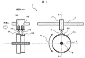
- FIG. 1 is a configuration diagram of a position detection apparatus 1 according to the present embodiment.
- FIG. 2 is a configuration diagram when FIG. 1 is viewed from an arrow A, and is a configuration diagram illustrating a gap between the magnetic core member and the coil of the position detection device 1 according to the present embodiment and the object to be measured.
- the sensor 2 includes two excitation coils, with the first coil facing the reference surface 9A and the sensing surface 9B of the DUT 4 as the reference coil 8A and the second coil as the sensing coil 8B.
- the sensor 2 is fixed to the sensor mounting portion 3. Further, the device under test 4 is supported by the device under test support 5, but rotates in the direction of the rotation direction 6.
- the gap 7A between the reference surface 9A of the object to be measured 4 and the sensor 2 is constant even when the object to be measured 4 rotates in the rotation direction 6 because the reference surface 9A is an outer peripheral surface of a perfect circle.
- the gap 7B between the sensing surface 9B of the device under test 4 and the sensor 2 changes when the device under test 4 rotates in the rotation direction 6 because the sensing surface 9B is an elliptical outer peripheral surface.
- the air gaps 7A and 7B are made of a material having a low magnetic permeability such as space, resin, nonmagnetic glass, nonmagnetic ceramics, and nonmagnetic metal.
- the reference surface 9A and the sensing surface 9B may both be elliptical outer peripheral surfaces, and the elliptical eccentricity may be symmetric. In that case, the point where the gap difference due to the eccentricity of the two becomes equal is set as the zero point, and the shape which realizes the target output characteristic at the zero point is set.
- FIG. 2 shows a configuration in which the reference coil 8A and the sensing coil 8B are wound around a magnetic core member, and the reference coil 8A and the sensing coil 8B are attached to the magnetic core 10.
- the magnetic core 10 is disposed so as to face the reference surface 9A and the sensing surface 9B of the object 4 to be measured.
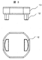
- the magnetic core 10 includes a coil mounting portion 12 for winding or inserting the reference coil 8A and the sensing coil 8B, and is made of the same magnetic material on the two detection surfaces 9A and 9B of the object 4 to be measured. It is an integral type, and has a configuration in which the influence of member variation of the magnetic core 10 is reduced. Moreover, the shape of the coil attachment part 12 was a bowl shape.
- the positional deviation of the magnetic core 10 disposed opposite to the detection surfaces 9A and 9B of the object 4 to be measured is suppressed compared to a separate type.
- the coil mounting portion 12 is shaped like a bowl, and the coil shape to be wound is also a bowl-shaped exciting coil 11, so that the detection area of the measurement object 4 with respect to the reference surface 9A and the sensing surface 9B is sufficiently large in the rotation direction. This is a secured configuration.
- the exciting coil 11 wound around the saddle-shaped coil mounting portion 12 of the magnetic core 10 has a low profile and a thin and flat saddle-like shape.
- the increase in inductance due to the apparent change in permeability when the exciting coil 11 is wound is suppressed, and the area and shape of the exciting coil 11 and the coil mounting portion 12 are optimized.
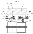
- FIG. 4 shows details of the section AA of FIG.
- the end surface 13 of the saddle-shaped coil mounting portion 12 of the magnetic core 10 and the end surfaces of the reference coil 8A and the sensing coil 8B, which are exciting coils, are arranged on the same plane, and the inside of the saddle-shaped coil mounting portion 12 ( A gap 14 is provided in the center of the magnetic core 10), and the reference coil 8A and the sensing coil 8B are arranged. That is, the reference coil 8 ⁇ / b> A and the sensing coil 8 ⁇ / b> B are provided eccentric to the coil attachment portion 12.
- the gap portion 14 is made of a material having a low magnetic permeability such as a space, resin, nonmagnetic glass, nonmagnetic ceramics, and nonmagnetic metal.
- the shape of the coil mounting portion 12 is almost dominant in the magnetic path to the object to be measured. Therefore, by reducing the proportion of the magnetic path that passes through the air region by such a shape.
- sensitivity reactance fluctuation
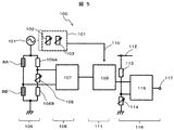
- the reference coil 8A and the sensing coil 8B, the bridge resistor A 104A and the bridge resistor B 104B, and the reference-sensing coil balance adjustment volume 105 form a bridge circuit 106.
- the bridge circuit 106 receives AC excitation from the oscillator 101 located upstream.
- the inductances of the reference coil 8A and the sensing coil 8B change due to the gaps 7A and 7B between the measured object 4 and the impedance, respectively.
- the intermediate voltage between the impedance of the reference coil 8A and the impedance of the sensing coil 8B and the intermediate voltage of the combined resistance of the bridge resistor A 104A, the bridge resistor B 104B, and the reference-sensing coil balance adjustment volume 105 is used as the differential amplifier 107 of the differential amplifier circuit 108 To detect the difference.
- the output of the differential amplifier 107 is input to the detector 109 of the detection circuit 111 that receives the synchronous signal 110 from the oscillator 101 and performs synchronous detection.
- the output of the detector 109 is input to the corrector 115 of the offset circuit 116 that offsets the output 117 together with the voltage obtained by dividing the reference voltage 112 by the voltage dividing resistor 113 and the offset adjusting volume 114.
- the reference-sensing coil balance adjustment volume 105 is used to adjust the output of the differential amplifier 107 to 0 at any position of the DUT 4 so that the reference coil 8A and the sensing coil are adjusted. 8B individual variations can be offset. Further, the output 117 can be adjusted by adjusting the offset adjustment volume 114 of the offset circuit 116, the frequency adjustment volume 102, and the gain adjustment volume 103 of the oscillator 101.
- the sensitivity has a frequency characteristic depending on the frequency f excited by the oscillator 101, and the sensitivity has a characteristic having an optimum value ⁇ 0 and a frequency f0.
- the sensitivity characteristic varies depending on the material (magnetic material or non-magnetic material) of the DUT 4, the optimum frequency f0 and sensitivity ⁇ 0 are set for each material.
- the configuration of the position detection device 1 in FIG. 1, the magnetic core 10 and the excitation coil 11 in FIGS. 2 to 4, and the circuit 100 in FIG. 5 can increase the sensitivity (reactance fluctuation) to the change in the gap 7.
- the overall magnification of the entire circuit 100 can be minimized, it is possible to reduce output fluctuations and noise due to environmental temperature changes of the circuit 100.
- the senor 2 detects a relative difference between the reference surface 9A and the sensing surface 9B and outputs an output 117. For this reason, even if the gap 7 between the sensor 2 and the absolute position changes due to the positional deviation between the measured object support 5 and the measured object 4, the output 117 is hardly affected.
- the output 117 is hardly affected. Furthermore, since the difference is detected even when the impedance characteristics change due to the temperature change of the reference coil 8A and the sensing coil 8B, the output 117 is hardly affected.
- FIGS. 7 and 8 show a magnetic core 15 separated from the magnetic core 10 shown in FIGS. 3 and 4, a reference coil 17A and a sensing coil 17B, an end surface 18 of the bowl-shaped leg portion of the magnetic core 15, the reference coil 17A, and sensing.
- the end face of the coil 17B is arranged on the same plane, and a gap 19 is provided inside the saddle-shaped sensor mounting part 16 of the magnetic core 15, and the reference coil 17A and the sensing coil 17B are wound around. Alternatively, it is inserted, arranged, and the distance of the gap 20 is optimized.
- the gaps 19 and 20 are made of a material having a low magnetic permeability such as space, resin, nonmagnetic glass, nonmagnetic ceramics, and nonmagnetic metal, as in the first embodiment.
- FIG. 9 to 12 are configuration diagrams of the position detection device 21.
- FIG. FIG. 9 shows a linear motion device 21 in which an object to be measured 24 has a detection surface 25 composed of peaks and troughs, and can be moved in the front-rear direction 26 by linear motion.
- the air gap 27 is provided and installed.
- the air gap 27 is made of a material having a low magnetic permeability such as a space, resin, nonmagnetic glass, nonmagnetic ceramics, and nonmagnetic metal.
- FIG. 10 shows the positional relationship between the detection surface 25 of the DUT 24 and the magnetic core 28.
- a first coil 29A and a second coil 29B are wound or inserted around the magnetic core 28, and the measurement object 24 moves in the front-rear direction 26.
- the GAP with the coil center of each of the first coil 29A and the second coil 29B at the Hi position is 30A and 30B.
- the GAP is 31 at the Mid position and 32A and 32B at the Lo position.
- the GAP characteristic 33A of the first coil and the GAP characteristic 33B of the second coil show symmetrical characteristics with respect to the Mid position.
- FIG. 11B shows the relationship between the movable position of the DUT 24 and the output 117, to which the detection circuit 100 of FIG. 5 is applied. Since the GAP has a symmetrical characteristic with respect to the Mid position, the offset output is shown. By applying the value 34, a linear characteristic based on the Mid position can be obtained.
- the position detection device 21 can be applied to detection of a pulley opening position and the like.
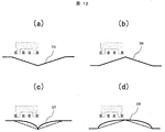
- FIG. 12 shows an example of the shape of the detection surface 25 as a modification.
- 12A shows a sloped concave mold 35 composed of peaks and valleys
- FIG. 12B shows a sloped convex mold 36
- FIGS. 12C and 12D show a curved concave mold 37 and a curved convex mold 38.
- the linear characteristics shown in FIG. 11B can be obtained by making the shapes symmetrical with respect to the Mid position.
- this invention is not limited to each above-mentioned Example, Various modifications are included. For example, the above-described embodiments have been described in detail for easy understanding of the present invention, and are not necessarily limited to those having all the configurations.
- a part of the configuration of one embodiment or modification can be replaced with the configuration of another embodiment or modification, and the configuration of another embodiment or modification can be replaced with the configuration of one embodiment or modification. It is also possible to add a configuration. Further, it is possible to add, delete, and replace other configurations for a part of the configuration of each embodiment or modification.
- SYMBOLS 1 Position detection apparatus, 2 ... Sensor, 3 ... Sensor mounting part, 4 ... Object to be measured, 5 ... Object to be measured support part, 6 ... Direction of rotation, 7 ... Air gap, 7A ... Air gap (reference), 7B ... Air gap ( Sensing), 8A ... reference coil, 8B ... sensing coil, 9A ... reference surface, 9B ... sensing surface, 10 ... magnetic core (integral type), 11 ... exciting coil, 12 ... coil mounting portion, 13 ... magnetic core and Coil end face, 14 ... gap (magnetic core-coil),
Landscapes
- Physics & Mathematics (AREA)
- General Physics & Mathematics (AREA)
- Transmission And Conversion Of Sensor Element Output (AREA)
- Measurement Of Length, Angles, Or The Like Using Electric Or Magnetic Means (AREA)
Abstract
温度変化による特性変化を低減し、測定精度を向上した位置検出装置を提供すること。 磁性体コア10と、コイルが取付けられるコイル取付け部12と、を備え、前記コイル取付け部は複数有し、前記磁性体コアと前記複数のコイル取付け部とを一体で構成した。
Description
本発明は、移動する非測定物の位置を測定する位置検出装置に係り、特に非接触で測定可能な位置検出装置に関する。
従来、エンジンが吸入する空気を過給するターボの羽を検出する位置検出装置において、コイルを利用した渦電流式の検出装置がターボセンサとして知られている。ターボセンサは、被測定物であるターボの羽とコイルとの空隙の距離に応じた振幅の信号を出力する。これにより、コンプレッサ又はタービンの羽根車の回転数をターボセンサによって検出する構成が提案されている。
しかしながら、ターボセンサは当該ターボセンサ上を通過するコンプレッサの羽根車における複数の羽根車を検出し、前記ターボセンサは、タービン及び前記コンプレッサを連結する連結軸の1回転当りのパルス信号を出力する。低回転域において過給機の回転数を精度良く検出できる点においては有用であるが、高回転域においては前記ターボセンサから出力される信号の周波数が非常に高くなる。従って、制御装置での処理の為に、前記ターボセンサの信号出力を分周器で変換する必要があり、部品点数の増大によるコスト高を招くという問題があった。
この点を考慮して、低回転域においても前記過給機の回転数を精度良く検出でき、且つ、高回転域でも前記制御装置への負荷を低減できる構成として、例えば、特許文献1に記載の構成がある。
特許文献1に記載の構成においては、ターボセンサが、過給機の羽根車における大羽根の通過に応じて第1振幅の第1信号を出力し、小羽根の通過に応じて第2振幅の第2信号を出力して、前記過給機の回転数を高精度に認識し、且つ、前記制御装置が、前記第1又は第2信号の何れか一方に基づいて前記過給機の回転数を認識するので、前期ターボセンサからの信号の周波数を低下させることができ、従って、前記制御装置への負荷を低減できる。
しかしながら、特許文献1に記載の構成は、ターボセンサと被測定物であるターボの羽根との線膨張係数差による、高温と低温での空隙の差、或いは温度変化によりコイルの特性が変化し、前記第1振幅または、第2振幅が変動し、第1振幅と第2振幅とを区別できなくなり、前記過給機の回転数の誤認識を招くという問題があった。
本発明は、温度変化による特性変化を低減し、測定精度を向上した位置検出装置の提供を目的とする。
本発明の位置検出装置は、例えば、磁性体コアと、コイルが取付けられるコイル取付け部と、を備え、前記コイル取付け部は複数有し、前記磁性体コアと前記複数のコイル取付け部とを一体で構成した。
本発明によれば、温度変化による特性変化を低減し、測定精度を向上した位置検出装置の提供が可能となる。
なお、上記した以外の課題、構成及び効果は、以下の実施形態の説明により明らかにされる。
以下、本発明に係る実施例を、図面を用いて説明する。なお、各図において、同一の構造である部分については、同一の符号を付け、説明を省略する。
図1乃至図3を用いて、本実施例に係る位置検出装置の構成について説明する。図1は、本実施例に係る位置検出装置1の構成図である。図2は図1を矢視Aから見た構成図であり、本実施例に係る位置検出装置1の磁性体コア部材及びコイルと被測定物との空隙を示す構成図である。 図1において、センサ2は、被測定物4の参照面9A、センシング面9Bに面した第1のコイルを参照コイル8A、第2のコイルをセンシングコイル8Bとし、2つの励磁コイルを備えている。なお、センサ2はセンサ取付け部3に固定される。また、被測定物4は、被測定物支持部5により支持されているが、回転方向6の向きに回転する。
被測定物4の参照面9Aとセンサ2との空隙7Aは、参照面9Aが真円の外周面である為、被測定物4が回転方向6に回転しても一定である。他方、被測定物4のセンシング面9Bとセンサ2との空隙7Bは、センシング面9Bが楕円の外周面である為、被測定物4が回転方向6に回転すると変化する。空隙7A及び7Bは空間、樹脂、非磁性ガラス、非磁性セラミックス、非磁性金属などの透磁率が低い材料からなる。
つまり、被測定物4が回転方向6に回転した場合、上記の参照面9Aとセンシング面9Bとセンサ2との空隙7A、7Bは、被測定物4の角度位置に応じて同一の空隙から徐々に差のある空隙に変化する。若しくは図示はしないが、参照面9Aとセンシング面9Bが両者とも楕円の外周面であり、楕円形状による偏心を対称とした構成としても良い。その際には両者の偏心による空隙差が等しくなる点を零点として、零点に対象となる出力特性を実現する形状とする。
図2は、参照コイル8A及びセンシングコイル8Bを磁性体コア部材に巻きまわした構成を示し、磁性体コア10に参照コイル8A及びセンシングコイル8Bを取付けた構成である。磁性体コア10は被測定物4の参照面9A及びセンシング面9Bに対向するように配置される。
磁性体コア10の形状の詳細を図3に示す。磁性体コア10は参照コイル8Aとセンシングコイル8Bを巻きまわす、または、挿入するためのコイル取付け部12を備えており、被測定物4の2つの検出面9A及び9Bで同一の磁性材からなる一体型であり、磁性体コア10の部材ばらつきの影響を小さくした構成である。また、コイル取付け部12の形状を蒲鉾形とした。
磁性体コア10とコイル取付け部12とを一体型とすることで、被測定物4の検出面9A及び9Bに対向配置する磁性体コア10の位置ずれを別体型と比較して、抑制することができる。また、コイル取付け部12の形状を蒲鉾形とし、巻きまわすコイル形状も蒲鉾形の励磁コイル11とすることで、被測定物4の参照面9A及びセンシング面9Bに対する検出面積を回転方向に十分に確保した構成である。
また、磁性体コア10の蒲鉾形のコイル取付け部12に巻きまわす励磁コイル11を低背とし、薄くて平たい蒲鉾型の形状とすることで、コイル単体のインダクタンスに対して、磁性体コア10に励磁コイル11を巻きまわした際の見かけの透磁率変化によるインダクタンス増加を抑制しとし、励磁コイル11とコイル取付け部12の面積・形状を最適化したものである。
また、図4は図1の断面A-Aの詳細を示したものである。磁性体コア10の蒲鉾形のコイル取付け部12の端面13および励磁コイルである参照コイル8A及びセンシングコイル8Bの端面を同一平面上となるように配置し、蒲鉾形のコイル取付け部12の内側(磁性体コア10の中心側)に空隙部14を設けて、参照コイル8A及びセンシングコイル8Bを配置する。すなわち、参照コイル8A及びセンシングコイル8Bはコイル取付け部12に対して偏心して設けられる。空隙部14は空間、樹脂、非磁性ガラス、非磁性セラミックス、非磁性金属などの透磁率が低い材料からなる。
図4のような構成により、被測定物への磁路は、コイル取付け部12の形状が概ね支配的となるため、このような形状により磁路のうち空気領域を通る割合を減少させることで、被測定物の空隙変化に対する励磁コイル11によるリアクタンス変動(以下、感度と定義)を大きくしつつ、環境温度の変化によるリアクタンス変動影響を少なくし、励磁コイル11によるリアクタンス変動との最適化で、環境温度の変化に対するインピーダンス変動を低減することができる。
図5は前記参照コイル8Aと前記センシングコイル8B、ブリッジ抵抗A104Aとブリッジ抵抗B104B及び参照-センシングコイルバランス調整ボリューム105によりブリッジ回路106の構成となっている。
ブリッジ回路106は上流にある発振器101より交流励磁を受ける。参照コイル8Aとセンシングコイル8Bは、それぞれの被測定物4との空隙7A、7Bによりインダクタンスが変化し、ひいてはそれぞれのインピーダンスが変化する。参照コイル8Aのインピーダンスとセンシングコイル8Bのインピーダンスの中間電圧と、ブリッジ抵抗A104Aとブリッジ抵抗B104B及び参照-センシングコイルバランス調整ボリューム105の合成抵抗との中間電圧を差動増幅回路108の差動増幅器107へ入力してその差分を検出する。
差動増幅器107の出力は、発振器101からの同期信号110を受けて同期検波する検波回路111の検波器109へ入力される。検波器109の出力は、基準電圧112を分圧抵抗113とオフセット調整ボリューム114で分圧された電圧と共に出力117をオフセットするオフセット回路116の補正器115へ入力される。
以上の回路構成にする事により、被測定物4の任意の位置において、参照-センシングコイルバランス調整ボリューム105により、差動増幅器107の出力が0となるように調整し、参照コイル8Aとセンシングコイル8Bの個別バラツキの相殺を行う事が出来る。また、オフセット回路116のオフセット調整ボリューム114や、発振器101の周波数調整ボリューム102やゲイン調整ボリューム103を調整することにより、出力117を調整する事が出来る。
また、図6に示す通り、発振器101より励磁する周波数fによって、感度は周波数特性を持ち、感度は最適値β0と周波数f0を持つ特性となる。また、被測定物4の材質(磁性材または非磁性材)により、感度特性は異なるので、材料毎に最適な周波数f0と感度β0を設定する。
図1の位置検出装置1や図2乃至図4の磁性体コア10及び励磁コイル11、図5の回路100の構成とすることにより、空隙7の変化に対する感度(リアクタンス変動)を大きくすることができ、回路100全体の総合倍率を最小にできるため、回路100の環境温度変化に起因する出力変動、ノイズ低減が可能である。
また、センサ2は参照面9Aとセンシング面9Bの相対的な差分を検出し出力117を出力する。この為、被測定物支持部5と被測定物4の位置ずれによりセンサ2との空隙7が変化して絶対位置が変化しても出力117は影響を受け難い。
また、環境温度変化により、同様にセンサ2と被測定物4の空隙7が変化しても出力117は影響を受け難い。更には、参照コイル8Aとセンシングコイル8Bが温度変化により、インピーダンス特性が変化した時もその差分を検出する為、出力117は影響を受け難い。
前記図1乃至図5の構成、図6の特性を考慮して構成することにより、コイル毎の特性のバラツキに起因したセンサ出力変動を抑制し、被測定物に対する感度が大きく、温度変化による特性変化を低減し、被測定物4の空隙変化を精度良く検出することができる。
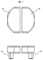
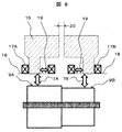
図7及び図8は図3及び図4の磁性体コア10を分離した磁性体コア15に参照コイル17A及びセンシングコイル17Bを磁性体コア15の蒲鉾形脚部の端面18と参照コイル17A及びセンシングコイル17Bの端面とを同一平面上に配置し、尚且つ、磁性体コア15の蒲鉾形のセンサ取付け部16との内側に空隙部19を設けて、参照コイル17A及びセンシングコイル17Bを巻きまわす、または挿入し、配置し、空隙部20の距離を最適化したものである。
これにより、分離型の磁性体コア15の部材ばらつきの影響を小さくすることを可能とした構成であり、一体型の磁性体コア10と同様の効果を得ることができる構成である。分離型の利点としてセンサへの実装性、組立性を容易にすることができるため、構成の変更が可能である。空隙部19及び20は実施例1と同様に空間、樹脂、非磁性ガラス、非磁性セラミックス、非磁性金属などの透磁率が低い材料からなる。
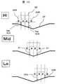
図9乃至図12は位置検出装置21の構成図を示す。図9は被測定物24が山と谷で構成される検出面25を有しており、直動で前後方向26に可動する直動装置21であり、センサ22はセンサ取付け部23に固定されており、空隙27を設けて、設置されている。空隙27は空間、樹脂、非磁性ガラス、非磁性セラミックス、非磁性金属などの透磁率が低い材料からなる。
図10は被測定物24の検出面25と磁性体コア28の位置関係を示したものである。磁性体コア28には第1コイル29A及び第2コイル29Bが巻きまわされ、または、挿入されており、前後方向26に被測定物24が可動することで可動位置によって、Hi、Mid、Loの位置関係となる。Hi位置で第1コイル29A及び第2コイル29Bの各々のコイル中心とのGAPは30A及び30Bとなり、同様にMid位置で31、Lo位置で32A及び32BのGAPとなる。
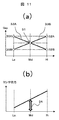
具体的には、図11(a)に示した被測定物24の可動位置とGAPとの関係となる。すわなち、第1コイルのGAP特性33Aと第2コイルのGAP特性33BはMid位置を基準として、対称特性を示す。
図11(b)は図5の検出回路100を適用し、被測定物24の可動位置と出力117の関係を示したもので、Mid位置を基準として、GAPは対称特性となるので、オフセット出力値34を施して、Mid位置を基準とした線形特性を得ることができる。位置検出装置21はプーリー開度位置等の検出に適用可能である。
また、図12には変形例として、検出面25の形状例を示す。図12(a)は山と谷で構成される斜面凹型35、図12(b)は斜面凸型36、図12(c)と(d)は曲面凹型37、曲面凸型38を示しており、何れもMid位置を基準とした対称形状とすることで、図11(b)に示す線形特性を得ることができる。
なお、本発明は上記した各実施例に限定されるものではなく、様々な変形例が含まれる。例えば、上記した実施例は本発明を分かりやすく説明するために詳細に説明したものであり、必ずしも全ての構成を備えるものに限定されるものではない。また、ある実施例又は変更例の構成の一部を他の実施例又は変更例の構成に置き換えることが可能であり、また、ある実施例又は変更例の構成に他の実施例又は変更例の構成を加えることも可能である。また、各実施例又は変更例の構成の一部について、他の構成の追加・削除・置換をすることが可能である。
なお、本発明は上記した各実施例に限定されるものではなく、様々な変形例が含まれる。例えば、上記した実施例は本発明を分かりやすく説明するために詳細に説明したものであり、必ずしも全ての構成を備えるものに限定されるものではない。また、ある実施例又は変更例の構成の一部を他の実施例又は変更例の構成に置き換えることが可能であり、また、ある実施例又は変更例の構成に他の実施例又は変更例の構成を加えることも可能である。また、各実施例又は変更例の構成の一部について、他の構成の追加・削除・置換をすることが可能である。
1…位置検出装置、2…センサ、3…センサ取付け部、4…被測定物、5…被測定物支持部、6…回転方向、7…空隙、7A…空隙(参照)、7B…空隙(センシング)、8A…参照コイル、8B…センシングコイル、9A…参照面、9B…センシング面、10…磁性体コア(一体型)、11…励磁コイル、12…コイル取付け部、13…磁性体コア及びコイル端面、14…空隙(磁性体コア-コイル)、
Claims (10)
- 磁性体コアと、
コイルが取り付けられる複数のコイル取付け部と、を備え、
前記磁性体コアと前記複数のコイル取付け部とを一体で構成した位置検出装置。 - 請求項1に記載の一検出装置において、
前記磁性体コアと前記複数のコイル取付け部とを同一の磁性材料で構成した位置検出装置。 - 請求項1に記載の位置検出装置において、
前記コイル取付け部は、蒲鉾形状であることを特徴とする位置検出装置。 - 請求項1に記載の位置検出装置において、
前記コイル取付け部は、前記磁性体コアの底面から突出して設けられていることを特徴とする位置検出装置。 - 請求項1に記載の位置検出装置において、
前記コイル取付け部は、励磁コイルが取付けられていることを特徴とする位置検出装置
。 - 上に従属
請求項5に記載の位置検出装置において、
前記励磁コイルは、前記コイル取付け部に対して偏心して取付けられていることを特徴とする位置検出装置。 - 上に従属
請求項6に記載の位置検出装置において、
前記励磁コイルと前記コイル取付け部との間に透磁率の低い材料が介在していることを特徴とする位置検出装置。 - 上に従属
請求項7に記載の位置検出装置において、
前記透磁率の低い材料とは、空気層、樹脂、非磁性ガラス、非磁性セラミックス、非磁性金属などであることを特徴とする位置検出装置。 - 請求項1に記載の位置検出装置であって、
前記コイル取付け部は、円筒型脚部付きの磁性体コアが左右対称の構造を持つ励磁位置検出装置。 - 請求項5に記載の位置検出装置であって、
前記磁性体コアと前記複数のコイル取付け部は同一材料で構成されており、
前記複数のコイル取付け部に取付けられた励磁コイルのうち、一方がセンシングコイルであり他方が参照用コイルであり、
被測定物の空隙の変化をインダクタンス変化の差分で検出することを特徴とする位置検出装置。
Priority Applications (1)
| Application Number | Priority Date | Filing Date | Title |
|---|---|---|---|
| JP2018502567A JP6695962B2 (ja) | 2016-02-29 | 2017-01-19 | 位置検出装置 |
Applications Claiming Priority (2)
| Application Number | Priority Date | Filing Date | Title |
|---|---|---|---|
| JP2016036557 | 2016-02-29 | ||
| JP2016-036557 | 2016-02-29 |
Publications (1)
| Publication Number | Publication Date |
|---|---|
| WO2017149975A1 true WO2017149975A1 (ja) | 2017-09-08 |
Family
ID=59742731
Family Applications (1)
| Application Number | Title | Priority Date | Filing Date |
|---|---|---|---|
| PCT/JP2017/001628 Ceased WO2017149975A1 (ja) | 2016-02-29 | 2017-01-19 | 位置検出装置 |
Country Status (2)
| Country | Link |
|---|---|
| JP (1) | JP6695962B2 (ja) |
| WO (1) | WO2017149975A1 (ja) |
Citations (5)
| Publication number | Priority date | Publication date | Assignee | Title |
|---|---|---|---|---|
| JPH03202703A (ja) * | 1989-12-29 | 1991-09-04 | Natl Aerospace Lab | インダクタンス形変位センサ |
| JP2001235307A (ja) * | 1999-03-15 | 2001-08-31 | Tadatoshi Goto | 回転型位置検出装置 |
| JP2012508983A (ja) * | 2008-11-14 | 2012-04-12 | アプライド マテリアルズ インコーポレイテッド | 縁部分解能強化渦電流センサ |
| US20150308859A1 (en) * | 2012-12-04 | 2015-10-29 | Robert Bosch Gmbh | method for monitoring a rotation of a compressor wheel |
| WO2016140149A1 (ja) * | 2015-03-05 | 2016-09-09 | 日立オートモティブシステムズ株式会社 | 位置検出装置 |
-
2017
- 2017-01-19 JP JP2018502567A patent/JP6695962B2/ja active Active
- 2017-01-19 WO PCT/JP2017/001628 patent/WO2017149975A1/ja not_active Ceased
Patent Citations (5)
| Publication number | Priority date | Publication date | Assignee | Title |
|---|---|---|---|---|
| JPH03202703A (ja) * | 1989-12-29 | 1991-09-04 | Natl Aerospace Lab | インダクタンス形変位センサ |
| JP2001235307A (ja) * | 1999-03-15 | 2001-08-31 | Tadatoshi Goto | 回転型位置検出装置 |
| JP2012508983A (ja) * | 2008-11-14 | 2012-04-12 | アプライド マテリアルズ インコーポレイテッド | 縁部分解能強化渦電流センサ |
| US20150308859A1 (en) * | 2012-12-04 | 2015-10-29 | Robert Bosch Gmbh | method for monitoring a rotation of a compressor wheel |
| WO2016140149A1 (ja) * | 2015-03-05 | 2016-09-09 | 日立オートモティブシステムズ株式会社 | 位置検出装置 |
Also Published As
| Publication number | Publication date |
|---|---|
| JPWO2017149975A1 (ja) | 2018-10-18 |
| JP6695962B2 (ja) | 2020-05-20 |
Similar Documents
| Publication | Publication Date | Title |
|---|---|---|
| US10330498B2 (en) | Sensor arrangement for the contactless sensing of angles of rotation on a rotating part | |
| US9207100B2 (en) | Magnetic position sensor with field direction measurement and flux collector | |
| JPWO2016140149A1 (ja) | 位置検出装置 | |
| US20040085063A1 (en) | Rotation sensor and method for detecting a rotation angle of a rotating member | |
| EP1898185B1 (en) | Position sensor | |
| CN108457984B (zh) | 磁轴承装置及真空泵 | |
| US6860159B2 (en) | Rotation sensor | |
| KR102775045B1 (ko) | 유도형 위치 센서의 측정 범위를 한정하기 위한 방법 | |
| EP2771646A1 (en) | Magnetic flux enhancer system for reluctance type sensors | |
| US20240192030A1 (en) | Position sensor for bearingless slice motors | |
| JP2003194642A (ja) | 電磁式トルクセンサ | |
| JP6695962B2 (ja) | 位置検出装置 | |
| JPH03506071A (ja) | 回転角検出測定装置 | |
| US6563412B2 (en) | Rotary variable differential transformer | |
| US11656100B2 (en) | Angular displacement sensor | |
| CN106461421A (zh) | 用于确定轴的位移的传感器装置 | |
| JP5249279B2 (ja) | 位置センサ | |
| JP4346280B2 (ja) | 回動角センサ | |
| JPH10148641A (ja) | 角加速度センサ | |
| Choi et al. | High sensitivity inductive sensing system for position measurement | |
| JP4219597B2 (ja) | 回転センサ | |
| JP2017044140A (ja) | ターボ用回転センサ及びターボチャージャ | |
| RU2398241C1 (ru) | Способ определения скорости движения | |
| CN111630350A (zh) | 旋转角度检测装置 | |
| US20020180423A1 (en) | Angular measurement system having an integrated ferraris sensor |
Legal Events
| Date | Code | Title | Description |
|---|---|---|---|
| ENP | Entry into the national phase |
Ref document number: 2018502567 Country of ref document: JP Kind code of ref document: A |
|
| NENP | Non-entry into the national phase |
Ref country code: DE |
|
| 121 | Ep: the epo has been informed by wipo that ep was designated in this application |
Ref document number: 17759447 Country of ref document: EP Kind code of ref document: A1 |
|
| 122 | Ep: pct application non-entry in european phase |
Ref document number: 17759447 Country of ref document: EP Kind code of ref document: A1 |