WO2017149575A1 - Noeud central, terminal sans fil, procédé de communication et support non temporaire lisible par ordinateur - Google Patents
Noeud central, terminal sans fil, procédé de communication et support non temporaire lisible par ordinateur Download PDFInfo
- Publication number
- WO2017149575A1 WO2017149575A1 PCT/JP2016/004982 JP2016004982W WO2017149575A1 WO 2017149575 A1 WO2017149575 A1 WO 2017149575A1 JP 2016004982 W JP2016004982 W JP 2016004982W WO 2017149575 A1 WO2017149575 A1 WO 2017149575A1
- Authority
- WO
- WIPO (PCT)
- Prior art keywords
- request message
- nas request
- message
- core node
- wireless terminal
- Prior art date
Links
- 238000004891 communication Methods 0.000 title claims abstract description 60
- 238000000034 method Methods 0.000 title claims description 25
- 238000012545 processing Methods 0.000 claims abstract description 95
- 238000001514 detection method Methods 0.000 claims abstract description 17
- 230000005540 biological transmission Effects 0.000 claims description 44
- 230000004044 response Effects 0.000 claims description 17
- 239000000725 suspension Substances 0.000 claims 1
- 238000007726 management method Methods 0.000 description 15
- 238000010586 diagram Methods 0.000 description 10
- 238000011084 recovery Methods 0.000 description 7
- 101100435066 Caenorhabditis elegans apn-1 gene Proteins 0.000 description 3
- 238000006243 chemical reaction Methods 0.000 description 2
- 238000004590 computer program Methods 0.000 description 2
- 230000006870 function Effects 0.000 description 2
- 230000003321 amplification Effects 0.000 description 1
- 238000013144 data compression Methods 0.000 description 1
- 238000000354 decomposition reaction Methods 0.000 description 1
- 230000006837 decompression Effects 0.000 description 1
- 230000003111 delayed effect Effects 0.000 description 1
- 238000005516 engineering process Methods 0.000 description 1
- 230000010354 integration Effects 0.000 description 1
- 230000007774 longterm Effects 0.000 description 1
- 238000013507 mapping Methods 0.000 description 1
- 238000010295 mobile communication Methods 0.000 description 1
- 238000003199 nucleic acid amplification method Methods 0.000 description 1
- 230000003287 optical effect Effects 0.000 description 1
- 239000013307 optical fiber Substances 0.000 description 1
- 238000004321 preservation Methods 0.000 description 1
- 230000011218 segmentation Effects 0.000 description 1
- 239000004065 semiconductor Substances 0.000 description 1
- 230000003068 static effect Effects 0.000 description 1
Images


Classifications
-
- H—ELECTRICITY
- H04—ELECTRIC COMMUNICATION TECHNIQUE
- H04W—WIRELESS COMMUNICATION NETWORKS
- H04W28/00—Network traffic management; Network resource management
- H04W28/02—Traffic management, e.g. flow control or congestion control
- H04W28/0247—Traffic management, e.g. flow control or congestion control based on conditions of the access network or the infrastructure network
-
- H—ELECTRICITY
- H04—ELECTRIC COMMUNICATION TECHNIQUE
- H04W—WIRELESS COMMUNICATION NETWORKS
- H04W28/00—Network traffic management; Network resource management
- H04W28/02—Traffic management, e.g. flow control or congestion control
- H04W28/0284—Traffic management, e.g. flow control or congestion control detecting congestion or overload during communication
-
- H—ELECTRICITY
- H04—ELECTRIC COMMUNICATION TECHNIQUE
- H04W—WIRELESS COMMUNICATION NETWORKS
- H04W28/00—Network traffic management; Network resource management
- H04W28/02—Traffic management, e.g. flow control or congestion control
- H04W28/0289—Congestion control
-
- H—ELECTRICITY
- H04—ELECTRIC COMMUNICATION TECHNIQUE
- H04W—WIRELESS COMMUNICATION NETWORKS
- H04W76/00—Connection management
- H04W76/10—Connection setup
- H04W76/18—Management of setup rejection or failure
-
- H—ELECTRICITY
- H04—ELECTRIC COMMUNICATION TECHNIQUE
- H04W—WIRELESS COMMUNICATION NETWORKS
- H04W76/00—Connection management
- H04W76/30—Connection release
- H04W76/38—Connection release triggered by timers
-
- H—ELECTRICITY
- H04—ELECTRIC COMMUNICATION TECHNIQUE
- H04W—WIRELESS COMMUNICATION NETWORKS
- H04W8/00—Network data management
- H04W8/02—Processing of mobility data, e.g. registration information at HLR [Home Location Register] or VLR [Visitor Location Register]; Transfer of mobility data, e.g. between HLR, VLR or external networks
- H04W8/08—Mobility data transfer
-
- H—ELECTRICITY
- H04—ELECTRIC COMMUNICATION TECHNIQUE
- H04W—WIRELESS COMMUNICATION NETWORKS
- H04W16/00—Network planning, e.g. coverage or traffic planning tools; Network deployment, e.g. resource partitioning or cells structures
- H04W16/14—Spectrum sharing arrangements between different networks
-
- H—ELECTRICITY
- H04—ELECTRIC COMMUNICATION TECHNIQUE
- H04W—WIRELESS COMMUNICATION NETWORKS
- H04W60/00—Affiliation to network, e.g. registration; Terminating affiliation with the network, e.g. de-registration
-
- H—ELECTRICITY
- H04—ELECTRIC COMMUNICATION TECHNIQUE
- H04W—WIRELESS COMMUNICATION NETWORKS
- H04W8/00—Network data management
- H04W8/02—Processing of mobility data, e.g. registration information at HLR [Home Location Register] or VLR [Visitor Location Register]; Transfer of mobility data, e.g. between HLR, VLR or external networks
- H04W8/06—Registration at serving network Location Register, VLR or user mobility server
-
- H—ELECTRICITY
- H04—ELECTRIC COMMUNICATION TECHNIQUE
- H04W—WIRELESS COMMUNICATION NETWORKS
- H04W88/00—Devices specially adapted for wireless communication networks, e.g. terminals, base stations or access point devices
- H04W88/14—Backbone network devices
Definitions
- the present invention relates to a core node, a wireless terminal, a communication method, and a program, and more particularly to a core node, a wireless terminal, a communication method, and a program that execute congestion control.
- the mobile communication system has a wireless terminal, a wireless access network (Radio Access Network: RAN), and a mobile core network.
- the mobile core network includes a relay node that relays user plane data and a control node that relays control plane data.
- the relay nodes are, for example, SGW (Serving Gateway), PGW (Packet data network Gateway), and the like.
- the control node is, for example, MME (Mobility Management Entity).
- the control node executes, for example, mobility management (Mobility Management: MM) and session management (Session Management: SM).
- the relay node and the control node may be referred to as a core node.
- the control node transmits a NAS (Non-Access Stratum) message to the wireless terminal in order to execute mobility management and session management. Further, the control node receives a NAS message transmitted from the wireless terminal.
- the NAS message is a control message that is not terminated in the RAN and is transparently transmitted between the wireless terminal and the MME without depending on the RAN radio access scheme.
- Non-Patent Document 1 describes a detailed explanation regarding the NAS message.
- Non-Patent Document 1 discloses a technology related to congestion control for suppressing overload or congestion in the mobile core network. For example, when the MME receives a NAS message related to session management or mobility management from a wireless terminal when the device itself is in a congested state, the MME rejects processing related to the received NAS message. At this time, the MME transmits a rejection message specifying the back-off timer value to the wireless terminal.
- the wireless terminal does not transmit the NAS message to the MME until the back-off timer value specified in the MME expires. In this way, the MME reduces the processing load in the congestion state.
- Non-Patent Document 1 retransmits the NAS message to the core node after the back-off timer value expires.
- the core node transmits a rejection message to the wireless terminal again. Therefore, if the NAS message is retransmitted while the congestion state continues, the core node has a problem that the processing load increases and the time until recovery from the congestion state is delayed.
- An object of the present invention is to provide a core node, a wireless terminal, a communication method, and a program that can reduce NAS request messages transmitted to the core node when the congestion state of the core node is detected. .
- the core node includes a congestion state detection unit that detects a congestion state of its own device, a communication unit that receives a NAS request message transmitted from a wireless terminal, and a message that stores the NAS request message.
- a wireless terminal includes a transmitting unit that transmits a NAS request message to a core node, and a receiving unit that receives a response message to the NAS request message, wherein the transmitting unit receives from the core node
- the NAS request message is not transmitted, and when a rejection message indicating that processing related to the NAS request message is not performed is received from the core node, the NAS The request message is retransmitted to the core node.
- the communication method detects the congestion state of the own device, receives the NAS request message transmitted from the wireless terminal, and detects the NAS request while the congestion state of the own device is detected.
- the message is stored, and the processing related to the NAS request message is suspended while the congestion state of the own device is detected.
- the program according to the fourth aspect of the present invention detects the congestion state of its own device, receives the NAS request message transmitted from the wireless terminal, and detects the NAS request message while the congestion state of its own device is detected. Is stored, and the computer is caused to suspend processing related to the NAS request message while the congestion state of the own device is detected.
- the present invention it is possible to provide a core node, a wireless terminal, a communication method, and a program that can reduce NAS request messages transmitted to the core node when the congestion state of the core node is detected.
- FIG. 3 is a configuration diagram of a core node according to the first exemplary embodiment
- FIG. 3 is a configuration diagram of a communication system according to a second exemplary embodiment. It is a figure explaining the flow of a process which MME concerning Embodiment 2 transmits a rejection message. It is a figure explaining the flow of a process when MME concerning Embodiment 2 recovers from a congestion state.
- It is a block diagram of UE concerning Embodiment 2.
- FIG. It is a figure explaining the flow of the process which stops transmission of the NAS request message in UE concerning Embodiment 2, and the process which restarts transmission of a NAS request message.
- FIG. 10 is a diagram for explaining a processing flow at the time of congestion according to the second embodiment
- FIG. 10 is a diagram for explaining a processing flow at the time of congestion according to the third embodiment
- It is a block diagram of UE40 concerning each embodiment.
- It is a block diagram of the core node 10 concerning each embodiment.
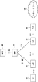
- FIG. 1 shows a configuration example of the core node 10 according to the first exemplary embodiment of the present invention.
- the core node 10 is a node arranged in the mobile core network, and may be a control node or a relay node.
- the core node 10 may be a computer device that operates when a processor executes a program stored in a memory.
- the core node 10 communicates with the wireless terminal 20 via the network 30.
- the network 30 may be a RAN, for example.
- the wireless terminal 20 may be, for example, a mobile phone terminal, a smart phone terminal, a tablet terminal, or an M2M (Machine to Machine) terminal having a communication function.
- the M2M terminal may be paraphrased as an MTC (Machine Type Communication) terminal, for example.
- the core node 10 includes a congestion state detection unit 11, a control unit 12, a communication unit 13, and a message storage unit 14.
- the congestion state detection unit 11, the control unit 12, the communication unit 13, and the message storage unit 14 may be configured by software or modules that execute processing when the processor executes a program stored in the memory. .
- the congestion state detection unit 11, the control unit 12, the communication unit 13, and the message storage unit 14 may be configured by hardware such as a circuit or a chip.
- the congestion state detection unit 11 detects the congestion state of the core node 10.
- the congestion state of the core node 10 may be a state where the processing load of the core node 10 is high.
- the state where the processing load is high may be, for example, a state where the processor usage rate or the memory usage rate of the core node 10 is higher than a predetermined threshold.
- the congestion state may be a state where the number of messages transmitted or received in the core node 10 is greater than a predetermined threshold.
- the congestion state may be a state where the number of wireless terminals 20 managed or controlled by the core node 10 is greater than a predetermined threshold.
- the communication unit 13 receives the NAS request message transmitted from the wireless terminal 20.
- the NAS request message is a NAS message used in an Attach request, a session (bearer) request, a location update request, or the like.
- the location update may be TAU (Tracking Area Update) or RAU (Routing Area Update), for example.
- the message storage unit 14 stores the NAS request message received by the communication unit 13 while the congestion state is detected in the congestion state detection unit 11 and the congestion state in the core node 10 is detected.
- the time during which the congestion state is detected may be from when the congestion state detection unit 11 detects the congestion state to when the congestion state detection unit 11 detects that the congestion state is recovered.
- the message storage unit 14 temporarily stores the NAS request message in order to temporarily hold the processing related to the NAS request message.
- the control unit 12 suspends the processing related to the NAS request message while the congestion state of the core node 10 is continued.
- the process related to the NAS request message may be, for example, a process related to an Attach request, a session request, or a location update request.
- the control unit 12 executes processing related to the NAS request message stored in the message storage unit 14.
- the message storage unit 14 stores a NAS request message to be processed after recovering from the congestion state while the congestion state continues.
- the core node 10 transmits a rejection message for rejecting the processing related to the NAS request message transmitted from the wireless terminal 20 when the own device is congested.
- the processing related to the NAS request message is suspended without being sent to 20.
- the core node 10 stores the NAS request message in the message storage unit 14. Thereby, when the core node 10 executes processing of the NAS request message transmitted from the wireless terminal 20 after recovering from the congestion state, the core node 10 does not need to cause the wireless terminal 20 to retransmit the NAS request message, and stores the message.
- the NAS request message stored in the unit 14 can be used.
- the core node 10 can avoid receiving the NAS request message retransmitted from the wireless terminal 20 while the congestion state is detected, thereby preventing an increase in processing load. Can do.
- the communication system of FIG. 2 shows a configuration example of a communication system defined in 3GPP, and includes a UE (User Equipment) 40, an eNB 50, an MME 60, an SGW 70, a PGW 80, an HSS (Home Subscriber Server) 90, and an external network 100.
- UE 40 is used as a generic term for wireless terminals in 3GPP.
- the UE 40 corresponds to the radio terminal 20 in FIG.
- the UE 40 may be an MTC device or the like, for example.
- the eNB 50 is a base station that supports LTE (Long Term Evolution) defined in 3GPP as a radio access method.
- the eNB 50 is arranged in the RAN.
- the MME 60, the SGW 70, and the PGW 80 correspond to the core node 10 in FIG.
- S1-MME is defined as a reference point between the MME 60 and the eNB 50.
- S1-U is defined as a reference point between the eNB 50 and the SGW 70.
- S5 is defined as a reference point between the SGW 70 and the PGW 80.
- the HSS 90 manages subscriber data regarding a plurality of UEs including the UE 40.
- the HSS 90 manages a plurality of APN (Access Point Name) information that can be specified by each UE.
- S6a is defined as a reference point between the HSS 90 and the MME 60.
- the external network 100 is a network different from the mobile core network.
- the external network 100 may be the so-called Internet or a packet data network (Packet Data Network: PDN).
- PDN Packet Data Network
- the external network may be a network managed by a provider that provides communication services to the UE 40, for example.
- the communication service may be referred to as, for example, an application service, a cloud service, or an Internet service.
- the provider providing the communication service may be, for example, an ISP (Internet Service Provider) or an ASP (Application Service Provider).
- APN is used as information for identifying the external network 100. That is, the UE 40 can communicate with a communication device arranged in the external network 100 by specifying an APN indicating the external network 100. In other words, the UE 40 can receive a service provided by the external network 100 by designating an APN indicating the external network 100.
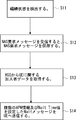
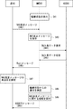
- the MME 60 has the same configuration as the core node 10 of FIG.
- the congestion state detection unit 11 detects a congestion state in the MME 60 (S11).
- the MME 60 may execute NAS-level mobility management congestion control that is executed in an overload state that does not depend on a specific APN as the congestion control.
- the control unit 12 rejects a NAS request message related to session management or mobility management while the congestion state continues. In other words, the control unit 12 does not execute processing related to the NAS request message while the congestion state continues.
- the communication unit 13 stores the received NAS request message in the message storage unit 14 (S12).
- the communication part 13 acquires the subscriber data regarding UE40 from HSS90 (S13).
- the subscriber data regarding the UE 40 includes a plurality of APNs that can be specified by the UE 40. Or the subscriber data regarding UE40 may contain all the APN which UE40 can designate.
- the communication unit 13 transmits to the UE 40 a Wait message in which a plurality of APNs including the APN specified in the NAS request message received in Step S12 and Wait Time values are set (S14).
- the Wait message is a message indicating that the MME 60 suspends processing related to the NAS request message transmitted when the congestion state of the MME 60 continues.
- the Wait ⁇ ⁇ Time value indicates a time during which the UE 40 suspends retransmission after transmitting the NAS request message.
- the Wait Time value may be referred to as a back-off timer value.
- the Wait Time value may indicate a time during which the UE 40 suspends retransmission of the NAS request message after receiving the Wait message. That is, after transmitting the NAS request message, the UE 40 does not retransmit the NAS request message to the MME 60 until the Wait Time value expires.
- the control unit 12 In the Wait Time value, a different value may be set for each UE according to a predetermined criterion. For example, the control unit 12 counts the number of NAS request messages transmitted in the past for each UE, and when the number of NAS request messages exceeds the threshold value, sets the Wait Time value to be long, If the number does not exceed the threshold, the Wait Time value may be set short. Alternatively, when the number of NAS request messages exceeds the threshold, the control unit 12 sets the WaitWTime value short, and when the number of NAS request messages does not exceed the threshold, the control unit 12 may set the Wait Time value long. Good.
- the UE 40 stops the transmission of the NAS request message specifying a plurality of APNs set in the Wait message.
- the MME 60 can prevent receiving the retransmission message of the NAS request message received in Step S12 by setting the APN specified in the NAS request message received in Step S12 in the Wait message.
- the UE 40 can set a plurality of APNs other than the APN specified in the NAS request message received in step S12 in the Wait message. As a result, the MME 60 can reduce the number of NAS request messages received when the congestion state continues.
- the congestion state detection unit 11 detects that the core node 10 has recovered from the congestion state (S21). For example, the congestion state detection unit 11 may determine that the core node 10 has recovered from the congestion state when the number of NAS request messages to be processed falls below a predetermined threshold. Alternatively, the congestion state detection unit 11 may determine that the core node 10 has recovered from the congestion state when the processor or memory usage rate of the core node 10 falls below a predetermined threshold.
- the communication unit 13 transmits an Accept message in which a plurality of APNs set in the Wait message are set to the UE 40 (S22).
- the control unit 12 takes out the NAS request message stored in the message storage unit 14.
- the control unit 12 executes processing related to the extracted NAS request message.
- the communication unit 13 transmits an Accept message to the UE 40 in order to permit transmission of the NAS request message specifying the APN set in the Accept message.
- the communication unit 13 may set all the APNs set in the Wait message as the Accept message, or may set some APNs among the APNs set in the Wait message as the Accept message.
- the congestion state may be recovered in stages depending on the processor or memory usage rate.
- the communication unit 13 may transmit an Accept message to the UE 40 in accordance with the stepwise recovery from the congestion state. For example, the communication unit 13 may transmit an Accept message at each stage of 10% recovery from the congestion state, 30% recovery, 50% recovery, or 100% recovery. Further, the communication unit 13 may set some APNs among a plurality of APNs set in the Wait message in the Accept message that is transmitted in response to the gradual recovery from the congestion state. That is, the communication unit 13 may divide and set all APNs set in the Wait message into a plurality of Accept messages.
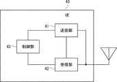
- the UE 40 includes a transmission unit 41, a reception unit 42, and a control unit 43.
- the transmission unit 41, the reception unit 42, and the control unit 43 may be software, modules, or the like that are executed by a processor executing a program stored in a memory.
- the transmission unit 41, the reception unit 42, and the control unit 43 may be hardware such as a circuit or a chip.
- the transmission unit 41 transmits a NAS request message to the MME 60 via the eNB 50.
- the eNB 50 transfers the NAS request message to the MME 60 without terminating the NAS request message.
- the receiving unit 42 receives a response message to the NAS request message transmitted from the MME 60 via the eNB 50.
- the response message to the NAS request message is, for example, a Wait message and an Accept message.
- the transmission unit 41 When receiving the Wait message indicating that the processing related to the NAS request message is suspended from the MME 60 in the receiving unit 42, the transmission unit 41 does not transmit the NAS request message specifying the APN set in the Wait message to the MME 60. .
- the transmission unit 41 when the APN_1 specified in the transmitted NAS request message is set in the Wait message, the transmission unit 41 does not retransmit the NAS request message specifying APN_1.
- the transmission unit 41 when an APN other than APN_1 is set in the Wait message, the transmission unit 41 does not transmit a NAS request message specifying the APN set in the Wait message.
- the transmission unit 41 does not transmit or retransmit the NAS request message before the Wait_Time value set in the Wait message expires.
- the control unit 43 may start the timer after the transmission unit 41 receives the NAS request message or after receiving the Wait message for the transmitted NAS request message.
- the transmission unit 41 or the control unit 43 may check whether or not the Wait ⁇ Time value has expired using the activated timer.
- the transmitter 41 may transmit or retransmit the NAS request message after the WaitWTime value expires.
- the transmitting unit 41 can also transmit to the MME 60 a NAS request message that specifies an APN that is different from the APN specified in the previously transmitted NAS request message.
- the control part 43 may stop the timer which was started, when an Accept message is received.
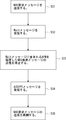
- the transmission unit 41 transmits a NAS request message to the eNB 50 via a wireless communication line (S31).
- the transmission unit 41 transmits a NAS request message specifying the APN associated with the service to be used to the eNB 50.
- the receiving unit 42 receives a Wait message from the MME 60 via the eNB 50 (S32).
- the Wait message a plurality of APNs that are prohibited from being used and Wait Time values are set.
- the plurality of APNs set in the Wait message include the APN specified in the NAS request message transmitted in step S31.
- the transmission unit 41 stops transmitting a NAS request message designating a plurality of APNs set in the Wait message before the designated Wait Time value expires (S33).
- the receiving unit 42 receives an ACCEPT message from the MME 60 via the eNB 50 (S34).
- the ACCEPT message a plurality of APNs that can be used are set.
- the APN set in the ACCEPT message may be all APNs set in the Wait message, or may be some of the APNs set in the Wait message.
- the transmission unit 41 resumes transmission of a NAS request message in which one APN selected from a plurality of APNs that can be used is set (S35).
- the ACCEPT message is a message used for notifying that the processing related to the NAS request message transmitted in step S31 has been completed. Therefore, after the receiving unit 42 receives the ACCEPT message in the receiving unit 42, the transmitting unit 41 may transmit a NAS request message specifying an APN different from the APN set in the NAS request message transmitted in step S31 to the eNB 50.
- the transmission unit 41 may resume the transmission of the NAS request message to the eNB 50 when the ACCEPT message is not transmitted even after the WaitWTime value expires. Or the transmission part 41 may stop transmission of a NAS request message to eNB50, when an ACCEPT message is not transmitted even after Wait-Time value expires, until an ACCEPT message is received.
- the MME 60 detects a congestion state (S41).
- UE40 transmits a NAS request message to MME60 via eNB50 (S42).
- S41 a congestion state
- S42 a NAS request message
- S42 an APN associated with the service used by the UE 40 is set.
- the MME 60 stores the NAS request message received in step S42 in the message storage unit 14 (S43). In other words, the MME 60 suspends processing related to the NAS request message received in Step S42.
- the MME 60 transmits a subscriber data request message to the HSS 90 in order to acquire the subscriber data of the UE 40 managed in the HSS 90 (S44).
- Identification information of the UE 40 is set in the subscriber data request message.
- the identification information of the UE 40 may be, for example, IMSI (International Mobile Subscriber Identity).
- the HSS 90 transmits, to the MME 60, a subscriber data response message in which subscriber data including information on all APNs that can be specified by the UE 40 is set (S45).
- the HSS 90 includes subscriber data including only information related to the predetermined APN among all APNs that can be specified by the UE 40.
- the predetermined APN may be a plurality of APNs.
- the predetermined APN may be determined according to a standard such as an APN whose NAS message transmission frequency is higher than a threshold value, for example. That is, the predetermined APN may be an APN that has a large influence on the processing load in the MME 60.
- the MME 60 transmits a Wait message in which all APNs included in the subscriber data are set to the UE 40 (S46).
- the MME 60 may set only the APN specified in step S42 and the APN satisfying the standard in the Wait message among all the APNs according to a predetermined standard.
- An APN that satisfies a predetermined criterion may be, for example, an APN whose frequency set in the NAS request message is higher than a threshold.
- the UE 40 suspends transmission of NAS request messages related to all APNs set in the Wait message (S47). In other words, the UE 40 stops transmitting the NAS request message specifying the APN set in the Wait message. Specifically, the UE 40 retransmits the NAS request message transmitted in step S42 and an APN other than the APN specified in the NAS request message transmitted in step S42, and sets the APN set in the Wait message. Stop sending the specified NAS request message.
- the UE 40 stops transmitting all NAS request messages.
- the MME 60 detects that the congestion state has been recovered (S48). Next, the MME 60 executes processing related to the NAS request message stored in step S43 (S49). Next, the MME 60 transmits an ACCEPT message indicating that the processing related to the NAS request message has been executed to the UE 40 (S50).
- the UE 40 After receiving the ACCEPT message, the UE 40 can transmit a NAS request message specifying an APN other than the APN specified in the NAS request message in step S42.
- the MME 60 can store the received NAS request message in order to suspend processing related to the received NAS request message while the congestion state continues. it can. Furthermore, the MME 60 can transmit a Wait message to the UE 40 while storing the NAS request message. As a result, the UE 40 can recognize that the processing related to the NAS request message is suspended, and does not retransmit the NAS request message. Therefore, since the MME 60 does not receive the retransmitted NAS request message, it is possible to prevent an increase in processing load due to the reception of the NAS request message.
- the MME 60 can set a plurality of APNs in the Wait message. As a result, the MME 60 can avoid not only the retransmission message related to the NAS request message received once, but also the reception of the NAS request message in which an APN different from the APN specified in the NAS request message received once is specified. it can.
- the MME 60 can execute processing related to the stored NAS request message. That is, the MME 60 does not need to request the UE 40 to retransmit the NAS request message by storing the NAS request message that has been suspended. Thereby, the number of messages transmitted between the UE 40 and the MME 60 can be reduced.
- Steps S51 to S57 are the same as steps S41 to S47 in FIG.
- the MME 60 transmits the Wait message to the UE 40 again (S58).
- the UE 40 suspends retransmission of the NAS request message until the Wait Time value set in the received Wait message expires (S59).
- steps S60 to S62 are the same as steps S48 to S50 in FIG. 7, detailed description thereof is omitted.
- the MME 60 may transmit the Wait message twice, but the MME 60 may transmit the Wait message to the UE 40 three times or more. Further, the MME 60 may determine in advance the number of transmissions of the upper limit Wait message. When the number of transmissions of the Wait message reaches the upper limit value, the MME 60 may discard the stored NAS request message and transmit a REJECT message to the UE 40.
- the REJECT message is a message used to notify the UE 40 that it has refused to execute the processing related to the NAS request message.
- the MME 60 may set a back-off timer value in the REJECT message.
- the congested MME 60 when receiving the NAS request message from the UE 40, the congested MME 60 transmits a Wait message to the UE 40 as long as the number of NAS request messages that can be held is not exceeded, and notifies that the NAS request message has been held. However, when the number of holdable NAS request messages is exceeded, a Reject message may be transmitted to the UE 40 to notify that the NAS request message has been discarded.
- the UE 40 When the UE 40 receives the REJECT message, the UE 40 resends the NAS request message after the back-off timer value set in the REJECT message expires. Or UE40 may transmit the NAS request message which designated APN different from APN designated to the NAS request message transmitted in step S52 to MME60.
- the REJECT message is a message defined as a message to be transmitted when processing related to the NAS request message is rejected in 3GPP.
- the MME 60 newly defines a Cancel message or the like as a message for notifying the UE 40 that the stored NAS request message has been discarded when the number of transmissions of the Wait message reaches the upper limit. Also good. That is, when the number of transmissions of the Wait message reaches the upper limit value, the MME 60 notifies the UE 40 that the stored NAS request message has been discarded as a REJECT message already defined in 3GPP. Or a new message not defined in 3GPP may be used.
- a Cancel message may be defined as a message for requesting the MME 60 to withdraw the pending NAS request message.
- the MME 60 discards the NAS request message that has already been received and held from the UE 40 and transmits a Reject message to the UE 40.
- the Cancel message may include information regarding which NAS request message is discarded.
- the MME 60 can transmit the Wait message multiple times before recovering from the congestion state. Further, the MME 60 can transmit a REJECT message or a Cancel message to the UE 40 when the number of times to transmit the Wait message reaches the upper limit. As a result, the MME 60 can prompt the UE 40 to resume transmission of the NAS request message.
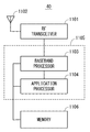
- FIG. 9 is a block diagram illustrating a configuration example of the UE 40.
- the Radio-Frequency (RF) transceiver 1101 performs analog RF signal processing to communicate with the eNB 50. Analog RF signal processing performed by the RF transceiver 1101 includes frequency up-conversion, frequency down-conversion, and amplification.
- RF transceiver 1101 is coupled with antenna 1102 and baseband processor 1103. That is, the RF transceiver 1101 receives modulation symbol data (or OFDM symbol data) from the baseband processor 1103, generates a transmission RF signal, and supplies the transmission RF signal to the antenna 1102. Further, the RF transceiver 1101 generates a baseband received signal based on the received RF signal received by the antenna 1102 and supplies this to the baseband processor 1103.
- modulation symbol data or OFDM symbol data
- the baseband processor 1103 performs digital baseband signal processing (data plane processing) and control plane processing for wireless communication.
- Digital baseband signal processing consists of (a) data compression / decompression, (b) data segmentation / concatenation, (c) ⁇ transmission format (transmission frame) generation / decomposition, and (d) transmission path encoding / decoding.
- E modulation (symbol mapping) / demodulation
- IFFT Inverse Fast Fourier Transform
- control plane processing includes layer 1 (eg, transmission power control), layer 2 (eg, radio resource management, hybrid automatic repeat request (HARQ) processing), and layer 3 (eg, attach, mobility, and call management). Communication management).
- the digital baseband signal processing by the baseband processor 1103 includes signal processing of Packet Data Convergence Protocol (PDCP) layer, Radio Link Control (RLC) layer, MAC layer, and PHY layer. But you can. Further, the control plane processing by the baseband processor 1103 may include Non-Access Stratum (NAS) protocol, RRC protocol, and MAC ⁇ CE processing.
- PDCP Packet Data Convergence Protocol
- RLC Radio Link Control
- MAC Medium Access Stratum
- PHY Packet Data Convergence Protocol
- the control plane processing by the baseband processor 1103 may include Non-Access Stratum (NAS) protocol, RRC protocol, and MAC ⁇ CE processing.
- NAS Non-Access Stratum
- the baseband processor 1103 includes a modem processor (eg, Digital Signal Processor (DSP)) that performs digital baseband signal processing and a protocol stack processor (eg, Central Processing Unit (CPU) that performs control plane processing, or Micro Processing Unit. (MPU)).
- DSP Digital Signal Processor
- protocol stack processor eg, Central Processing Unit (CPU) that performs control plane processing, or Micro Processing Unit. (MPU)
- CPU Central Processing Unit
- MPU Micro Processing Unit.
- a protocol stack processor that performs control plane processing may be shared with an application processor 1104 described later.
- the application processor 1104 is also called a CPU, MPU, microprocessor, or processor core.
- the application processor 1104 may include a plurality of processors (a plurality of processor cores).
- the application processor 1104 is a system software program (Operating System (OS)) read from the memory 1106 or a memory (not shown) and various application programs (for example, a call application, a web browser, a mailer, a camera operation application, music playback)
- OS Operating System
- the baseband processor 1103 and the application processor 1104 may be integrated on a single chip, as indicated by the dashed line (1105) in FIG.
- the baseband processor 1103 and the application processor 1104 may be implemented as one System on Chip (SoC) device 1105.
- SoC System on Chip
- An SoC device is sometimes called a system Large Scale Integration (LSI) or chipset.
- the memory 1106 is a volatile memory, a nonvolatile memory, or a combination thereof.
- the memory 1106 may include a plurality of physically independent memory devices.
- the volatile memory is, for example, Static Random Access Memory (SRAM), Dynamic RAM (DRAM), or a combination thereof.
- the non-volatile memory is a mask Read Only Memory (MROM), Electrically Erasable Programmable ROM (EEPROM), flash memory, hard disk drive, or any combination thereof.
- the memory 1106 may include an external memory device accessible from the baseband processor 1103, the application processor 1104, and the SoC 1105.
- Memory 1106 may include an embedded memory device integrated within baseband processor 1103, application processor 1104, or SoC 1105.
- the memory 1106 may include a memory in a Universal Integrated Circuit Card (UICC).
- UICC Universal Integrated Circuit Card
- the memory 1106 may store a software module (computer program) including an instruction group and data for performing processing by the UE 40 described in the plurality of embodiments.
- the baseband processor 1103 or the application processor 1104 may be configured to perform the processing of the UE 40 described in the above-described embodiment by reading the software module from the memory 1106 and executing the software module.
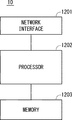
- FIG. 10 is a block diagram illustrating a configuration example of the core node 10.
- the core node 10 includes a network interface 1201, a processor 1202, and a memory 1203.
- the network interface 1201 is used for communicating with network nodes (e.g., eNB, MME, SGW, P-GW).
- the network interface 1201 may include, for example, a network interface card (NIC) compliant with IEEE 802.3 series.
- NIC network interface card
- the processor 1202 reads the software (computer program) from the memory 1203 and executes it, thereby performing the processing of the core node 10 described using the sequence diagram and the flowchart in the above-described embodiment.
- the processor 1202 may be, for example, a microprocessor, MPU, or CPU.
- the processor 1202 may include a plurality of processors.
- the memory 1203 is configured by a combination of a volatile memory and a nonvolatile memory.
- Memory 1203 may include storage located remotely from processor 1202. In this case, the processor 1202 may access the memory 1203 via an I / O interface not shown.
- the memory 1203 is used for storing software module groups.
- the processor 1202 can perform the processing of the core node 10 described in the above-described embodiment by reading these software module groups from the memory 1203 and executing them.
- each of the processors included in the UE 40 and the core node 10 in the above-described embodiment includes one or more instructions including instructions for causing the computer to execute the algorithm described with reference to the drawings. Run multiple programs.
- Non-transitory computer readable media include various types of tangible storage media (tangible storage medium).
- Examples of non-transitory computer-readable media include magnetic recording media (eg flexible disks, magnetic tapes, hard disk drives), magneto-optical recording media (eg magneto-optical discs), CD-ROMs (Read Only Memory), CD-Rs, CD-R / W, semiconductor memory (for example, mask ROM, PROM (Programmable ROM), EPROM (Erasable ROM), flash ROM, RAM (Random Access Memory)) are included.
- the program may also be supplied to the computer by various types of temporary computer-readable media. Examples of transitory computer readable media include electrical signals, optical signals, and electromagnetic waves.
- the temporary computer-readable medium can supply the program to the computer via a wired communication path such as an electric wire and an optical fiber, or a wireless communication path.
- a congestion state detection unit for detecting the congestion state of the own device; A communication unit for receiving a NAS request message transmitted from a wireless terminal; A message storage unit for storing the NAS request message; A core node comprising: a control unit that stores the NAS request message in a message storage unit and suspends processing related to the NAS request message while a congestion state of the own device is detected.
- the controller is The core node according to supplementary note 1, wherein when the own device recovers from a congestion state, the core node executes processing related to the NAS request message stored in the message storage unit.
- the communication unit is When the control unit determines to suspend the process related to the NAS request message, the control unit transmits a Wait message notifying the wireless terminal to suspend the process related to the NAS request message.
- Core node. (Appendix 4)
- the communication unit is The core node according to supplementary note 3, wherein a plurality of the Wait messages are transmitted to the wireless terminal before processing related to the NAS request message is executed.
- the controller is When the number of transmissions of the Wait message reaches an upper limit value, it is determined not to perform processing related to the NAS request message;
- the communication unit is The core node according to appendix 3 or 4, wherein a rejection message indicating that processing related to the NAS request message is not performed is transmitted to the wireless terminal.
- the communication unit is When the Wait message in which the back-off timer value is set is transmitted to the wireless terminal and the congestion state of the own device continues at the time when the back-off timer value expires, a new back-off timer value is set. 6.
- the communication unit is The core node according to any one of appendices 2 to 6, wherein the core node transmits an accept message to the wireless terminal when the device recovers from the congestion state and the processing related to the NAS request message is completed.
Landscapes
- Engineering & Computer Science (AREA)
- Computer Networks & Wireless Communication (AREA)
- Signal Processing (AREA)
- Databases & Information Systems (AREA)
- Mobile Radio Communication Systems (AREA)
Abstract
L'invention concerne un noeud central permettant de réduire les messages de requête de strate de non accès (NAS) transmis audit noeud, tandis que l'encombrement dans le noeud central continue. À cet effet, le noeud central (10) selon l'invention comprend une unité de détection d'état d'encombrement (11) destinée à détecter un état d'encombrement dans le dispositif de noeud central, une unité de communication (13) destinée à recevoir un message de requête NAS transmis par un terminal sans fil (20), une unité de sauvegarde de message (14) destinée à sauvegarder le message de requête NAS, ainsi qu'une unité de commande (12) destinée à différer le traitement relatif au message de requête NAS alors que l'état d'encombrement du dispositif de noeud central est détecté.
Priority Applications (2)
| Application Number | Priority Date | Filing Date | Title |
|---|---|---|---|
| JP2018502855A JP6583531B2 (ja) | 2016-03-03 | 2016-11-28 | コアノード、無線端末、及び通信方法 |
| US16/081,251 US20190069196A1 (en) | 2016-03-03 | 2016-11-28 | Core node, radio terminal, communication method, and non-transitory computer readable medium |
Applications Claiming Priority (2)
| Application Number | Priority Date | Filing Date | Title |
|---|---|---|---|
| JP2016-040987 | 2016-03-03 | ||
| JP2016040987 | 2016-03-03 |
Publications (1)
| Publication Number | Publication Date |
|---|---|
| WO2017149575A1 true WO2017149575A1 (fr) | 2017-09-08 |
Family
ID=59743525
Family Applications (1)
| Application Number | Title | Priority Date | Filing Date |
|---|---|---|---|
| PCT/JP2016/004982 WO2017149575A1 (fr) | 2016-03-03 | 2016-11-28 | Noeud central, terminal sans fil, procédé de communication et support non temporaire lisible par ordinateur |
Country Status (3)
| Country | Link |
|---|---|
| US (1) | US20190069196A1 (fr) |
| JP (1) | JP6583531B2 (fr) |
| WO (1) | WO2017149575A1 (fr) |
Citations (2)
| Publication number | Priority date | Publication date | Assignee | Title |
|---|---|---|---|---|
| JP2011119823A (ja) * | 2009-12-01 | 2011-06-16 | Fujitsu Ltd | パケット中継装置および輻輳制御方法 |
| WO2014099432A2 (fr) * | 2012-12-21 | 2014-06-26 | Qualcomm Incorporated | Techniques pour réduire une congestion de réseau dans un système de communication sans fil |
Family Cites Families (9)
| Publication number | Priority date | Publication date | Assignee | Title |
|---|---|---|---|---|
| JP4493707B2 (ja) * | 2008-08-07 | 2010-06-30 | 株式会社エヌ・ティ・ティ・ドコモ | 移動通信方法、移動局及び交換局 |
| AU2011215752A1 (en) * | 2010-02-12 | 2012-09-06 | Interdigital Patent Holdings, Inc | Access control and congestion control in machine-to-machine communication |
| KR101752707B1 (ko) * | 2011-01-03 | 2017-07-03 | 삼성전자 주식회사 | 이동통신 시스템에서 혼잡 제어 방법 |
| US20120218889A1 (en) * | 2011-02-24 | 2012-08-30 | Interdigital Patent Holdings, Inc. | Handling of low priority devices |
| US9113355B2 (en) * | 2011-04-07 | 2015-08-18 | Htc Corporation | Method of handling signaling and data transmission for machine-type communication |
| EP2608567A1 (fr) * | 2011-12-13 | 2013-06-26 | Panasonic Corporation | Déclenchement de dispositif et contrôle de la congestion |
| EP2852210B1 (fr) * | 2012-06-14 | 2018-09-19 | Huawei Technologies Co., Ltd. | Procédé et dispositif pour traiter une surcharge de messages |
| KR101611965B1 (ko) * | 2012-10-05 | 2016-04-12 | 엘지전자 주식회사 | 무선 통신 시스템에서 다중 우선순위 제어 방법 및 장치 |
| KR102210906B1 (ko) * | 2014-03-31 | 2021-02-02 | 콘비다 와이어리스, 엘엘씨 | M2m 서비스 층과 3gpp 네트워크 사이의 과부하 제어 및 조율 |
-
2016
- 2016-11-28 JP JP2018502855A patent/JP6583531B2/ja active Active
- 2016-11-28 US US16/081,251 patent/US20190069196A1/en not_active Abandoned
- 2016-11-28 WO PCT/JP2016/004982 patent/WO2017149575A1/fr active Application Filing
Patent Citations (2)
| Publication number | Priority date | Publication date | Assignee | Title |
|---|---|---|---|---|
| JP2011119823A (ja) * | 2009-12-01 | 2011-06-16 | Fujitsu Ltd | パケット中継装置および輻輳制御方法 |
| WO2014099432A2 (fr) * | 2012-12-21 | 2014-06-26 | Qualcomm Incorporated | Techniques pour réduire une congestion de réseau dans un système de communication sans fil |
Non-Patent Citations (2)
| Title |
|---|
| "Handling of NAS requests with delay tolerant indicator in RAN", 3GPP TSG- RAN WG2 #72B R2-110462, 11 January 2011 (2011-01-11), XP050474790 * |
| 3GPP TS 23.401, 15 December 2015 (2015-12-15) * |
Also Published As
| Publication number | Publication date |
|---|---|
| US20190069196A1 (en) | 2019-02-28 |
| JPWO2017149575A1 (ja) | 2018-12-20 |
| JP6583531B2 (ja) | 2019-10-02 |
Similar Documents
| Publication | Publication Date | Title |
|---|---|---|
| US10791482B2 (en) | Core node, base station, radio terminal, communication method, radio resource allocation method, base station selection method, and readable medium | |
| EP3525497B1 (fr) | Entité de scef, terminal de communication, procédé de traitement de données, procédé de réception de données, et support non transitoire lisible par ordinateur | |
| EP3525532B1 (fr) | Dispositif de commande, procédé de radiomessagerie, et support lisible par ordinateur non-transitoire | |
| JP6693572B2 (ja) | システム、制御装置、Exposure Functionエンティティ、及び方法 | |
| TW201725928A (zh) | 處理無線資源控制連結的裝置及方法 | |
| US20240022901A1 (en) | Gateway device, mobility management device, base station, communication method, control method, paging method, and computer-readable medium | |
| US11425596B2 (en) | Control device, communication terminal, control method, non-transitory computer readable medium, MME, and base station for controlling a transmission resource using a communication pattern (CP) parameter | |
| JP2021170814A (ja) | サーバ装置及びサーバ装置の方法 | |
| CN110301156B (zh) | 通信终端、控制设备、通信系统和通信方法 | |
| JP7376166B2 (ja) | 第1のcnノード、第1のcnノードにおいて実行される方法、及びueにおいて実行される方法 | |
| JP6587030B2 (ja) | コアノード、及び通信方法 | |
| JP6583531B2 (ja) | コアノード、無線端末、及び通信方法 |
Legal Events
| Date | Code | Title | Description |
|---|---|---|---|
| WWE | Wipo information: entry into national phase |
Ref document number: 2018502855 Country of ref document: JP |
|
| NENP | Non-entry into the national phase |
Ref country code: DE |
|
| 121 | Ep: the epo has been informed by wipo that ep was designated in this application |
Ref document number: 16892420 Country of ref document: EP Kind code of ref document: A1 |
|
| 122 | Ep: pct application non-entry in european phase |
Ref document number: 16892420 Country of ref document: EP Kind code of ref document: A1 |