WO2017146249A1 - 瞬き検出システム、瞬き検出方法 - Google Patents
瞬き検出システム、瞬き検出方法 Download PDFInfo
- Publication number
- WO2017146249A1 WO2017146249A1 PCT/JP2017/007318 JP2017007318W WO2017146249A1 WO 2017146249 A1 WO2017146249 A1 WO 2017146249A1 JP 2017007318 W JP2017007318 W JP 2017007318W WO 2017146249 A1 WO2017146249 A1 WO 2017146249A1
- Authority
- WO
- WIPO (PCT)
- Prior art keywords
- signal
- blink
- detection
- threshold value
- threshold
- Prior art date
- Legal status (The legal status is an assumption and is not a legal conclusion. Google has not performed a legal analysis and makes no representation as to the accuracy of the status listed.)
- Ceased
Links
Images




Classifications
-
- A—HUMAN NECESSITIES
- A61—MEDICAL OR VETERINARY SCIENCE; HYGIENE
- A61B—DIAGNOSIS; SURGERY; IDENTIFICATION
- A61B5/00—Measuring for diagnostic purposes; Identification of persons
- A61B5/103—Measuring devices for testing the shape, pattern, colour, size or movement of the body or parts thereof, for diagnostic purposes
- A61B5/11—Measuring movement of the entire body or parts thereof, e.g. head or hand tremor or mobility of a limb
-
- A—HUMAN NECESSITIES
- A61—MEDICAL OR VETERINARY SCIENCE; HYGIENE
- A61B—DIAGNOSIS; SURGERY; IDENTIFICATION
- A61B3/00—Apparatus for testing the eyes; Instruments for examining the eyes
- A61B3/10—Objective types, i.e. instruments for examining the eyes independent of the patients' perceptions or reactions
- A61B3/113—Objective types, i.e. instruments for examining the eyes independent of the patients' perceptions or reactions for determining or recording eye movement
-
- G—PHYSICS
- G01—MEASURING; TESTING
- G01S—RADIO DIRECTION-FINDING; RADIO NAVIGATION; DETERMINING DISTANCE OR VELOCITY BY USE OF RADIO WAVES; LOCATING OR PRESENCE-DETECTING BY USE OF THE REFLECTION OR RERADIATION OF RADIO WAVES; ANALOGOUS ARRANGEMENTS USING OTHER WAVES
- G01S13/00—Systems using the reflection or reradiation of radio waves, e.g. radar systems; Analogous systems using reflection or reradiation of waves whose nature or wavelength is irrelevant or unspecified
- G01S13/02—Systems using reflection of radio waves, e.g. primary radar systems; Analogous systems
- G01S13/50—Systems of measurement based on relative movement of target
- G01S13/58—Velocity or trajectory determination systems; Sense-of-movement determination systems
Definitions
- the present invention relates to a blink detection system and a blink detection method.
- VDT Visual Display Terminal
- Blinking has the role of spreading the tear film and protecting the cornea. Acquisition of blink information is effective not only for grasping physical conditions such as fatigue, concentration and sleepiness, but also for preventing eye symptoms of VDT workers. It is.
- Non-Patent Document 1 a method based on machine learning has been proposed (for example, see Non-Patent Document 1).
- five feature values (voltage maximum value, time width, variance, raw signal variance, raw signal voltage maximum value) are defined for the blink signal, and SVM (Support Vector Vector Machine), one of machine learning, is defined. Identify blinks and non-blinks.
- the present invention has been made in view of the above points, and an object thereof is to provide a blink detection system using a Doppler sensor that does not require machine learning and enables highly accurate blink detection.
- This blink detection system obtains a Doppler sensor that obtains a Doppler signal, obtains an amplitude signal of the Doppler signal, divides the amplitude signal into a plurality of cells that are continuous in the time axis direction, and detects cells before and after not adjacent to the target cell
- a first detection unit that determines a first threshold value based on an amplitude value and detects a signal component that is equal to or higher than the first threshold value in the cell of interest; and a signal component that is equal to or higher than the first threshold value based on a blink waveform feature It is a requirement to have a blink determination unit that eliminates false detection from the above and determines the remaining signal components as blinks.
- 2 is an example of a Doppler signal obtained by a Doppler sensor 10; It is an example of the flowchart of the blink detection method which concerns on this Embodiment. It is a figure explaining CA-CFAR detection.
- It is a diagram amplitude signal A, the amplitude signal A M of the amplitude signal A by smoothing be described.
- It is an example of a peak of the second threshold value TH 2
- the following amplitude signal A M It is a figure explaining the determination of a peak height determination part.
- Is a diagram for describing each of the height difference M I and M Q of the I and Q signals. It is FIG. (1) explaining the maximum point and minimum point obtained from the smoothed I signal and Q signal. It is FIG. (2) explaining the maximum point and minimum point obtained from the smoothed I signal and Q signal.
- FIG. 1 is a functional block diagram illustrating a blink detection system according to this embodiment.
- the blink detection system 1 shown in FIG. 1 includes a Doppler sensor 10 and a signal processing unit 20 as main components.
- the Doppler sensor 10 is a sensor that detects the movement of the observation target (subject) by observing the frequency shift of the transmission signal and the reception signal due to the Doppler effect.
- an unmodulated continuous wave (CW: ContinuousConWave) is used as a transmission wave.
- the Doppler sensor 10 is arranged in the vicinity of the subject, receives a signal (reflected wave) reflected at the subject's eyelid or in the vicinity thereof, and obtains a Doppler signal by multiplying the frequency of the transmission signal by the received signal.
- Examples of the subject include a worker who works on an image display terminal (VDT), a vehicle driver, and the like.
- FIG. 2 is an example of a Doppler signal obtained by the Doppler sensor 10.
- the signal shown in FIG. 2 is obtained by obtaining a Doppler signal representing a frequency shift between a transmission signal and a reception signal as a function of time, an I signal that is an in-phase component of the transmission signal, and a quadrature phase. It is composed of Q signals that are (Quadrature) components.
- Movements of the surface of the body such as blinking, heartbeat and breathing, and body movement (movement by the body) can be observed by the Doppler sensor 10.
- the output signal of the Doppler sensor 10 also increases, so that the spectrum is spread and distributed to a high frequency region of about 50 Hz.
- Blink is a frequency range higher than heartbeat and respiration and lower than body motion, and the spectrum spreads to about 10 to 20 Hz.
- the signal processing unit 20 detects the blink of the subject based on the Doppler signal that is the output signal of the Doppler sensor 10.
- the signal processing unit 20 can appropriately use the I signal and the Q signal of the Doppler signal received by the Doppler sensor 10 as they are, or can generate an amplitude signal based on the I signal and the Q signal.
- the signal processing unit 20 includes a CA-CFAR (Cell Averaging Constant Constant Alarm Rate) detection unit 21, a body motion detection unit 22, a peak detection unit 23, and a blink determination unit 24.
- the blink determination unit 24 includes a peak height determination unit 241, a voltage level difference determination unit 242, and a phase change determination unit 243. The functions of these units will be described later with reference to the flowchart of FIG.
- the signal processing unit 20 may include, for example, a CPU (Central Processing Unit), a ROM (Read Only Memory), a RAM (Random Access Memory), a main memory, and the like. In this case, various functions of the signal processing unit 20 can be realized by reading a program recorded in the ROM or the like into the main memory and executing it by the CPU. However, part or all of the signal processing unit 20 may be realized only by hardware.
- the signal processing unit 20 may be physically configured by a plurality of devices.
- FIG. 3 is an example of a flowchart of the blink detection method according to the present embodiment.
- the blink detection method according to the present embodiment will be described with reference to FIG. 3 and other drawings as appropriate.
- the Doppler sensor 10 receives a reflected wave from the subject and obtains a Doppler signal.
- the Doppler signal obtained here includes, for example, an I signal and a Q signal as shown in FIG.
- step S102 noise is removed from the Doppler signal received in step S101.
- the noise removal may be performed in hardware by inserting a band pass filter or the like between the Doppler sensor 10 and the signal processing unit 20, or the output signal of the Doppler sensor 10 is directly input to the signal processing unit 20,
- the signal processing unit 20 may perform digital signal processing (such as a digital filter).
- step S102 may be executed as necessary.
- the CA-CFAR detector 21 as the first detector performs CA-CFAR detection based on the Doppler signal from which noise has been removed in step S102.
- the amplitude signal A is obtained from the Doppler signal (I signal and Q signal) from which noise has been removed, using Equation (1).
- the CA-CFAR detection it is preferable to use a signal whose pass band is about 5 to 50 Hz in step S102.
- the heart rate component is about 0.8 to 1.5 Hz
- the respiratory component is about 0.15 to 0.4 Hz. Therefore, by setting the pass band to about 5 to 50 Hz, the influence of the heart rate and respiration can be reduced. This is because it can be reduced.
- CA-CFAR detection is performed using the amplitude signal A.
- the first threshold TH 1 is determined based on a desired false alarm probability.
- the interested cell Cut: Cell under test
- a first threshold value TH 1 based on the amplitude values before and after the cell not adjacent to the Cut. Specifically, a predetermined number of cells immediately preceding the Cut and guard cell G F, a predetermined number of cells immediately after the Cut and guard cell G R, further, guard cell G F front cell F of a predetermined number of cells immediately before, guard cell a predetermined number of cells immediately after the G R and Riaseru R.
- the duration of the blink signal observed by the Doppler sensor 10 is empirically found to be about 0.4 seconds. Therefore, the cell length of each cell in FIG. 4 is preferably set to about 0.2 seconds.
- the guard cell G F , the guard cell G R , the front cell F, and the rear cell R are each composed of three cells. However, this is an example, and the guard cell G F , the guard cell G R , the front cell F, The number of cells constituting the rear cell R can be determined as appropriate.
- an average value A AVE of the amplitude value of the front cell F and the amplitude value of the rear cell R is calculated, and a value obtained by multiplying the average value A AVE by a coefficient ⁇ as shown in the equation (2) is set as the first threshold value TH 1 .
- guard cell G F and G R are not used for calculation of the first threshold value TH 1. This, Cut itself is a cell of interest is to prevent affecting the first threshold value TH 1.
- the CA-CFAR detector 21 detects a signal component equal to or higher than the first threshold TH 1 in Cut. Subsequently, the same detection is repeated while moving the position of Cut.
- the first threshold value TH 1 or more signal components is determined to be potentially blink, the process of step S106 (described later) is executed.
- the body motion detection unit 22 as the second detection unit performs body motion detection.
- Body motion detection is processing performed to detect a large body motion and exclude it from blink detection processing. For example, blinking in a situation where the vehicle is not in operation, such as when driving on a boring straight road or when the VDT work is concentrated, is detected. While the amplitude value due to blinking decreases, the amplitude value due to large body movement increases, it can be determined that a signal having a large amplitude value is due to body movement.
- the body motion detection unit 22 performs body motion detection based on the Doppler signal from which noise has been removed in step S102.
- the amplitude signal A is obtained from the Doppler signal from which noise has been removed, using Equation (1).
- the amplitude signal A shown in FIG. 5 is obtained using a signal (a signal in which heartbeat, respiration, and high frequency noise components are reduced) having a passband of about 5 to 25 Hz.
- the second threshold value TH 2 can be appropriately determined based on a pre experiment.
- Signal component amplitude signal A M is the second threshold value TH 2 or less, the body movement is determined as not being detected, the process proceeds to step S105.
- the peak detection section 23 performs peak detection of the second threshold value TH 2 The following amplitude signal A M at step S104.
- Figure 6 is an example of a peak of the second threshold value TH 2 The following amplitude signal A M detected in step S105. As shown in FIG. 6, a plurality of peaks are usually detected.
- step S103 and the processes in steps S104 and S105 are processes performed on the same Doppler signal obtained by the Doppler sensor 10 in step S101, and can be performed in parallel.
- step S106 the blink determination unit 24, the first threshold value TH 1 or more signal components in step S103, and the signal component peak is detected in step S105, the blink determination (false based on the characteristics of the blink waveform Detection removal).
- the signal component determined to be the processing target in step S106 by the CA-CFAR detection in step S103 or the peak detection in step S105 is likely to be blinking.
- the signal component determined to be the processing target in step S106 may include a peak of the heart rate and the respiratory component. Of FP occurs.
- the purpose of the process of step S106 is to remove these FPs.
- the peak height determination unit 241 removes FP by performing peak height determination on the signal component that is equal to or higher than the first threshold TH 1 in step S103 and the signal component in which the peak is detected in step S105. Specifically, the height of the peaks included in the first threshold value TH 1 or more signal components, and the peak height of the signal component peak is detected at step S105 and the reference value Sv respectively compared in step S103, A portion where the peak height is equal to or less than the reference value Sv is determined to be erroneous detection (non-blink).
- the peak height determination unit 241 determines that a portion where the peak height is equal to or less than the reference value Sv (a circled portion) is erroneously detected (non-blink).
- FIG. 7 is an example of a comparison between the height and the reference value Sv of the peak of the second threshold value TH 2
- the peak height included in the signal component is similarly compared with the reference value Sv.
- the reference value Sv is defined by a constant c times the average value P AVE of peak heights as shown in the equation (3).
- the constant c in the formula (3) is preferably set to about 0.7 empirically.
- the height of the peak changes depending on the state of blinking and the distance from the Doppler sensor 10, but in the case of long-time observation, it can be dealt with by updating the value of the reference value Sv.
- the voltage level difference determination unit 242 removes FP based on the level difference between the voltage value of the I signal and the voltage value of the Q signal.
- the high-pass filter removes heart rate and respiration frequency components from the Doppler signal (I signal and Q signal) obtained in step S101.
- the cut-off frequency of the high-pass filter can be set to about 5 Hz, for example.
- the phase change determination unit 243 removes the FP based on the total number of maximum points and minimum points of the voltage value of the I signal and the voltage value of the Q signal.
- a high-frequency component of the Doppler signal (I signal and Q signal) obtained in step S101 is removed and smoothed by a low-pass filter.
- the cut-off frequency of the low-pass filter can be set to about 25 Hz, for example.
- the fourth threshold TH 4 is set to 5 points, but the present invention is not limited to this.
- the fourth threshold TH 4 is set to 5 points, for example, in FIG. 9A, the minimum point is 1 point, so it is determined to be blinking. In FIG. 9B, the total number of maximum points and minimum points is 5 points. It is determined to be moving.
- step S106 the peak height determination unit 241 determines whether the peak height is equal to or lower than the reference value Sv, and the voltage height difference determination unit 242 determines both the height differences M I and M Q are the third threshold value. TH 3 or more signals, and the determination in smoothed I signal and the total number of both the fourth threshold value TH 4 or more signals obtained maximum and minimum points from the Q signal of the phase change determination unit 243 is excluded as FP.
- the first threshold value TH 1 or more signal components in step S103, and among the signal components peaks were detected in the step S105, the remaining signal components excluding the excluded signal components as FP in step S106 is the blink determination Is done.
- the processing order of the determination by the peak height determination unit 241, the determination by the voltage level difference determination unit 242, and the determination by the phase change determination unit 243 may be arbitrarily determined.
- steps S101 to S106 it is not necessary to execute all of steps S101 to S106, and at least steps S101, S103, and S106 (any one of peak height determination, voltage height difference determination, and phase change determination) are executed.
- the accuracy of blink detection can be improved.
- the accuracy of blink detection can be improved by executing steps S104 and S105.
- the accuracy of blink detection can be further improved by executing any one of peak height determination, voltage height difference determination, and phase change determination in step S106, and the accuracy of blink detection can be further increased by executing all three. It can be improved.
- the blink detection system 1 by dynamically determining the first threshold value TH 1 in CA-CFAR detection by CA-CFAR detector 21, robustness to the body of the fluctuations and noise And a blink detection failure (FN) can be reduced.
- the process of the blink determination unit 24 based on the characteristics of the blink waveform, it is possible to exclude fine body movements that are easily detected as blinks and reduce the number of false detections (FP). By combining these, machine learning is not required and highly accurate blink detection is possible.
- Experiment 1 is an experiment in different environments (1) and (2), and Experiment 2 is an experiment in different subjects A to D.
- Experiment 3 is an experiment for confirming the effect of processing by the blink determination unit 24 that reduces the FP generated by CA-CFAR detection.
- the subject sits still with his eyes meditated, and the body is affected by fluctuations.
- Situation 2 the body is moved back and forth and stopped alternately for 2 to 3 seconds each.
- the detection rate Rr and the matching rate Pr are used for the evaluation.
- the detection rate Rr indicates the proportion of blinks that can be detected among actual blinks
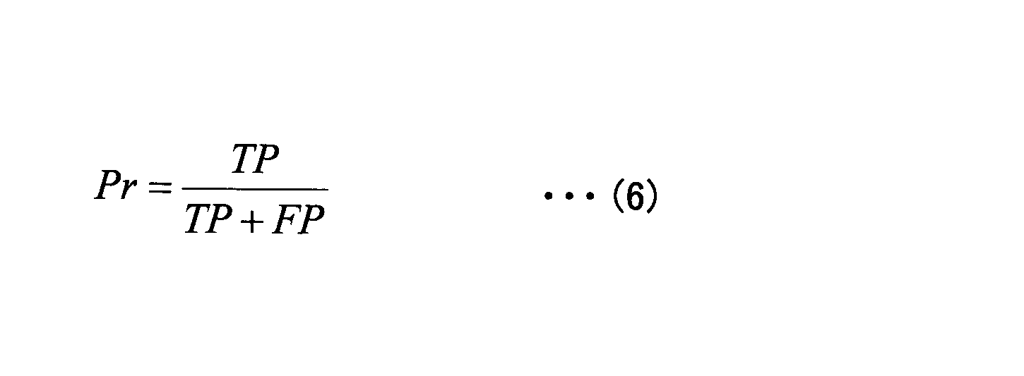
- the matching rate Pr indicates the proportion of correct answers among blinks that are detected, and is defined by Equations (5) and (6).
- TP represents the number of blinks that could be detected correctly
- FN represents the number of blinks that were not detected
- FP represents the number detected as blinks by mistake.
- Table 2 shows the results of Experiment 1 and the results of the conventional method as a comparison.
- the method using machine learning described in Non-Patent Document 1 is referred to as a conventional method, and the blink detection method according to the present embodiment described with reference to FIG.
- the blink detection performance is improved by learning various blink waveforms in advance using SVM, and a highly accurate detection rate Rr of 99.2% is achieved.
- the precision Pr is 90.2%, which is not a sufficient value. This is because the conventional method mistakenly detected subtle body movements and noises as blinks, and FP increased.
- the proposed method achieved high blink detection accuracy of about 99% for both detection rate Rr and relevance rate Pr.
- FP was reduced by applying robustness to body fluctuations and noise by applying CA-CFAR detection to blink signal detection.
- the processing of the blink determination unit 24 based on the characteristics of the blink waveform fine body movements that are easily detected as blinks are excluded, and FP is reduced.
- the proposed method can improve the accuracy of blink detection compared with the conventional method.
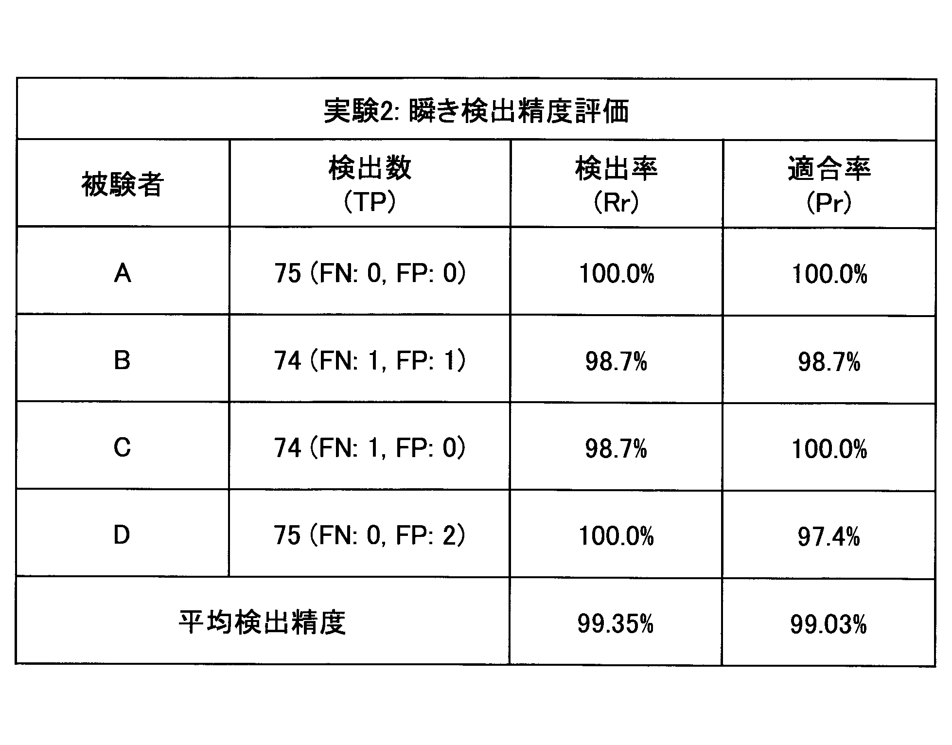
- the precision Pr was 97.4%, which was slightly lower than those of subjects A, B, and D. This is because the parameters (constant c, first threshold TH 1 , second threshold TH 2 , third threshold TH 3 , fourth threshold TH 4, etc.) in the determination process are set based on the subject A FP. This is thought to be because the effect of reduction was reduced. However, from this result, it was confirmed that the proposed method can achieve high blink detection accuracy of 99% or more on average.
- the precision Pr is further improved by setting each parameter in the determination process based on a plurality of subjects. Further, it is considered that the precision Pr is further improved by performing calibration for each subject before fine blink determination and finely adjusting each parameter for each subject. This calibration can fine-tune each parameter in an extremely short time unlike large-scale learning like the conventional method.
- the number of FPs can be reduced while increasing the number of TPs by combining the CA-CFAR detection by the CA-CFAR detection unit 21 and the FP exclusion process by the blink determination unit 24 as in the proposed method.
- high-accuracy blink detection in which the detection rate Rr and the matching rate Pr are both about 99% can be realized.
Landscapes
- Health & Medical Sciences (AREA)
- Life Sciences & Earth Sciences (AREA)
- Heart & Thoracic Surgery (AREA)
- Medical Informatics (AREA)
- Physics & Mathematics (AREA)
- Dentistry (AREA)
- Biophysics (AREA)
- Pathology (AREA)
- Engineering & Computer Science (AREA)
- Biomedical Technology (AREA)
- Physiology (AREA)
- Oral & Maxillofacial Surgery (AREA)
- Molecular Biology (AREA)
- Surgery (AREA)
- Animal Behavior & Ethology (AREA)
- General Health & Medical Sciences (AREA)
- Public Health (AREA)
- Veterinary Medicine (AREA)
- Radar Systems Or Details Thereof (AREA)
- Measurement Of The Respiration, Hearing Ability, Form, And Blood Characteristics Of Living Organisms (AREA)
Abstract
本瞬き検出システムは、ドップラー信号を得るドップラーセンサと、前記ドップラー信号の振幅信号を求め、前記振幅信号を時間軸方向に連続する複数のセルに分割し、注目するセルに隣接しない前後のセルの振幅値に基づいて第1閾値を決定し、前記注目するセルにおいて前記第1閾値以上の信号成分を検出する第1検出部と、瞬き波形の特徴に基づいて、前記第1閾値以上の信号成分の中から誤検出を除去し、残りの信号成分を瞬きと判定する瞬き判定部と、を有する。
Description
本発明は、瞬き検出システム及び瞬き検出方法に関する。
近年、コンピュータの画像表示端末(VDT:Visual Display Terminal)での作業の普及に伴い、多くの作業者から肩や腰、手、特に目の痛みを訴える事例が多く挙げられており、これらの事例はVDT症候群等と呼ばれている。長時間のVDT作業は、眼精疲労等の様々な眼症状を引き起こすため、VDT作業者の間で問題となっている。
瞬きは涙液膜を広げたり角膜を守ったりする役割があり、瞬き情報の取得は疲労度や集中度、眠気といった身体状態の把握のみならず、VDT作業者の眼症状を防ぐという観点でも有効である。
こうした背景から、瞬き情報の取得に注目した様々な取り組みが行われており、例えば、機械学習に基づく手法が提案されている(例えば、非特許文献1参照)。この手法では、瞬き信号について5つの特徴量(電圧最大値、時間幅、分散、生信号の分散、生信号の電圧最大値)を定義し、機械学習の一つであるSVM(Support Vector Machine)により瞬きと非瞬きを識別する。
これら特徴量は人や環境毎に異なるため、事前に様々な瞬きについて特徴量を学習することで、検出特性が向上する。しかし、機械学習を用いた手法では、人や環境毎に事前学習を行う必要があり、学習データとテストデータが適さない場合には検出精度が劣化してしまう。
C,Tamba and T.Ohtsuki,"Learning-based Blink Detection Using a Doppler Sensor,"IEICE technical report,vol.114,no.418,ASN2014-123,pp.97-102.Jan.2015.
本発明は、上記の点に鑑みてなされたものであり、機械学習が不要で高精度な瞬き検出を可能とする、ドップラーセンサを用いた瞬き検出システムを提供することを目的とする。
本瞬き検出システムは、ドップラー信号を得るドップラーセンサと、前記ドップラー信号の振幅信号を求め、前記振幅信号を時間軸方向に連続する複数のセルに分割し、注目するセルに隣接しない前後のセルの振幅値に基づいて第1閾値を決定し、前記注目するセルにおいて前記第1閾値以上の信号成分を検出する第1検出部と、瞬き波形の特徴に基づいて、前記第1閾値以上の信号成分の中から誤検出を除去し、残りの信号成分を瞬きと判定する瞬き判定部と、を有することを要件とする。
開示の技術によれば、機械学習が不要で高精度な瞬き検出を可能とする、ドップラーセンサを用いた瞬き検出システムを提供できる。
以下、図面を参照して、実施の形態の説明を行う。なお、各図面において、同一構成部分には同一符号を付し、重複した説明を省略する場合がある。
図1は、本実施の形態に係る瞬き検出システムを例示する機能ブロック図である。図1に示す瞬き検出システム1は、主要な構成要素として、ドップラーセンサ10と、信号処理部20とを有している。
ドップラーセンサ10は、ドップラー効果による送信信号と受信信号の周波数シフトを観測することで、観測対象(被験者)の動きを検出するセンサである。本実施の形態では、一例として、送信波として無変調連続波(CW:Continuous Wave)を用いる。
ドップラーセンサ10は被験者の近傍に配置され、被験者の瞼又はその近傍で反射された信号(反射波)を受信し、受信信号に送信信号の周波数を掛け合わせてドップラー信号を得る。被験者としては、例えば、画像表示端末(VDT)で作業する作業者、車両の運転者等が挙げられる。
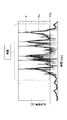
図2は、ドップラーセンサ10で得たドップラー信号の一例である。図2に示す信号は、送信信号と受信信号の間の周波数シフトを表わすドップラー信号を時間の関数として取得したものであり、送信信号と同相(In-phase)成分であるI信号、及び直交位相(Quadrature)成分であるQ信号で構成される。
瞬き、心拍や呼吸、体動(身体による動作)等の身体の表面の動きはドップラーセンサ10により観測できる。身体の表面積が広い体動の場合、ドップラーセンサ10の出力信号も大きくなるため、50Hz程度の高周波数領域までスペクトルが広がって分布する。
一方、心拍や呼吸等の小さな身体動作は、スペクトルが数Hz程度の低周波領域に分布する傾向にあり、心拍成分は0.8~1.5Hz程度、呼吸成分は0.15~0.4Hz程度の周波数となる。瞬きは、心拍や呼吸よりも高く、体動よりも低い周波数領域となり、約10~20Hzまでスペクトルが広がる。
従って、瞬き検出を行う際には、バンドパスフィルタ等を用いて適宜ノイズ除去を行うことが好ましい。
図1に戻り、信号処理部20は、ドップラーセンサ10の出力信号であるドップラー信号に基づいて、被験者の瞬きを検出する。信号処理部20は、適宜、ドップラーセンサ10で受信したドップラー信号のI信号及びQ信号をそのまま利用したり、I信号及びQ信号に基づいて振幅信号を生成したりすることができる。
信号処理部20は、CA-CFAR(Cell Averaging Constant False Alarm Rate)検出部21と、体動検出部22と、ピーク検出部23と、瞬き判定部24とを有している。又、瞬き判定部24は、ピーク高判定部241と、電圧高低差判定部242と、位相変化判定部243とを有している。これら各部の機能については、図3のフローチャートを参照しながら後述する。
信号処理部20は、例えば、CPU(Central Processing Unit)、ROM(Read Only Memory)、RAM(Random Access Memory)、メインメモリ等を含む構成とすることができる。この場合、信号処理部20の各種機能は、ROM等に記録されたプログラムがメインメモリに読み出されてCPUにより実行されることによって実現できる。但し、信号処理部20の一部又は全部は、ハードウェアのみにより実現されてもよい。又、信号処理部20は、物理的に複数の装置等により構成されてもよい。
図3は、本実施の形態に係る瞬き検出方法のフローチャートの一例である。図3を中心にして適宜他の図も参照しながら、本実施の形態に係る瞬き検出方法について説明する。
まず、ステップS101では、ドップラーセンサ10で被験者からの反射波を受信してドップラー信号を得る。ここで得るドップラー信号は、例えば、図2に示すようなI信号及びQ信号で構成されている。
次に、ステップS102では、ステップS101で受信したドップラー信号のノイズ除去を行う。ノイズ除去は、ドップラーセンサ10と信号処理部20との間にバンドパスフィルタ等を挿入してハードウェア的に行ってもよいし、ドップラーセンサ10の出力信号を直接信号処理部20に入力し、信号処理部20内においてディジタル信号処理(ディジタルフィルタ等)により行ってもよい。
又、除去するべきノイズの周波数(通過させるべき信号の周波数)は各処理により異なる場合があるから、通過帯域の異なる複数の信号を出力可能に構成しておくことが好ましい。例えば、通過帯域を5~50Hz程度とした信号、通過帯域を5~25Hz程度とした信号、ノイズ除去を行わない信号等を適宜出力させるように構成することができる。但し、ステップS102は必要に応じて実行すればよい。
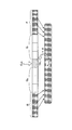
次に、ステップS103では、第1検出部であるCA-CFAR検出部21は、ステップS102においてノイズ除去されたドップラー信号に基づいてCA-CFAR検出を行う。まず、ノイズ除去されたドップラー信号(I信号及びQ信号)から式(1)により振幅信号Aを求める。なお、CA-CFAR検出では、ステップS102で通過帯域を5~50Hz程度とした信号を用いることが好ましい。前述のように、心拍成分は0.8~1.5Hz程度、呼吸成分は0.15~0.4Hz程度であるから、通過帯域を5~50Hz程度とすることで、心拍や呼吸の影響を低減できるからである。

次に、Cutに隣接しない前後のセルの振幅値に基づいて第1閾値TH1を決定する。具体的には、Cutの直前の所定数のセルをガードセルGF、Cutの直後の所定数のセルをガードセルGRとし、更に、ガードセルGFの直前の所定数のセルをフロントセルF、ガードセルGRの直後の所定数のセルをリアセルRとする。ドップラーセンサ10で観測された瞬き信号の時間長は、経験的に約0.4秒であることがわかっている。そこで、図4における各セルのセル長は0.2秒程度に設定することが好ましい。
なお、図4では、ガードセルGF、ガードセルGR、フロントセルF、及びリアセルRをそれぞれ3セルで構成しているが、これは一例であり、ガードセルGF、ガードセルGR、フロントセルF、及びリアセルRを構成するセル数は適宜決定することができる。
次に、フロントセルFの振幅値とリアセルRの振幅値の平均値AAVEを算出し、式(2)に示すように平均値AAVEを係数α倍したものを第1閾値TH1とする。なお、ガードセルGF及びGRは第1閾値TH1の算出には用いない。これは、注目するセルであるCut自身が第1閾値TH1へ影響することを防ぐためである。

以上のようにして第1閾値TH1が決定されると、CA-CFAR検出部21は、Cutにおいて第1閾値TH1以上の信号成分を検出する。引き続きCutの位置を移動させながら同様の検出を繰り返す。そして、第1閾値TH1以上の信号成分は、瞬きである可能性があると判断され、ステップS106(後述)の処理が実行される。
次に、ステップS104では、第2検出部である体動検出部22は、体動検出を行う。体動検出は、身体の大きな動きを検出し、瞬き検出処理から除外するために行う処理である。例えば、退屈な直線道路の運転中やVDT作業集中時等、動作中でない状況での瞬きを検出対象とする。瞬きによる振幅値は小さくなるのに対し、身体の大きな動きによる振幅値は大きくなるため、大きな振幅値を持つ信号は体動によるものであると判別できる。
具体的には、体動検出部22は、ステップS102においてノイズ除去されたドップラー信号に基づいて体動検出を行う。まず、ノイズ除去されたドップラー信号から式(1)により振幅信号Aを求める。ここでは、ステップS102で通過帯域を5~25Hz程度とした信号(心拍や呼吸、高周波雑音成分を低減した信号)を用いて図5に示す振幅信号Aを求める。
続いて、振幅信号Aを移動平均により平滑化した振幅信号AMを生成する。そして、振幅信号AMと第2閾値TH2とを比較する。そして、第2閾値TH2より大きな信号成分を体動によるものと判定する。なお、第2閾値TH2は、事前実験に基づいて適宜決定することができる。
振幅信号AMが第2閾値TH2以下である信号成分は、体動が検出されていないものと判断され、ステップS105へ進む。ステップS105では、ピーク検出部23は、ステップS104における第2閾値TH2以下の振幅信号AMのピーク検出を行う。図6は、ステップS105で検出された第2閾値TH2以下の振幅信号AMのピークの一例である。図6に示すように、通常は複数のピークが検出される。
ピーク検出部23において第2閾値TH2以下の振幅信号AMでピークが検出された信号成分は、瞬きである可能性があると判断され、ステップS106(後述)の処理が実行される。
なお、ステップS103の処理とステップS104及びS105の処理は、ステップS101でドップラーセンサ10で得た同一のドップラー信号に対して行われる処理であり、並行して行うことができる。
次に、ステップS106では、瞬き判定部24は、ステップS103において第1閾値TH1以上の信号成分、及びステップS105においてピークが検出された信号成分について、瞬き波形の特徴に基づいて瞬き判定(誤検出の除去)を行う。
ステップS103のCA-CFAR検出やステップS105のピーク検出でステップS106の処理対象であると判断された信号成分は、瞬きである可能性が高い。しかし、ステップS103やS105において心拍や呼吸成分を完全に取り除けず、ステップS106の処理対象であると判断された信号成分に、心拍や呼吸成分のピークが含まれている場合があるため、いくつかのFPが生じる。これらのFPを取り除くことがステップS106の処理の目的である。
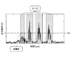
まず、ピーク高判定部241は、ステップS103において第1閾値TH1以上の信号成分、及びステップS105においてピークが検出された信号成分について、ピーク高判定を行うことでFPを取り除く。具体的には、ステップS103において第1閾値TH1以上の信号成分に含まれるピークの高さ、及びステップS105においてピークが検出された信号成分のピークの高さと基準値Svとをそれぞれ比較し、ピークの高さが基準値Sv以下の部分を誤検出(非瞬き)と判定する。
例えば、図7に示すように、ピーク高判定部241は、ピークの高さが基準値Sv以下の部分(丸で囲んだ部分)を誤検出(非瞬き)であると判定する。なお、図7は、ステップS105で検出された第2閾値TH2以下の振幅信号AMのピークの高さと基準値Svとを比較した例であるが、ステップS103において第1閾値TH1以上の信号成分に含まれるピークの高さについても同様に基準値Svと比較する。
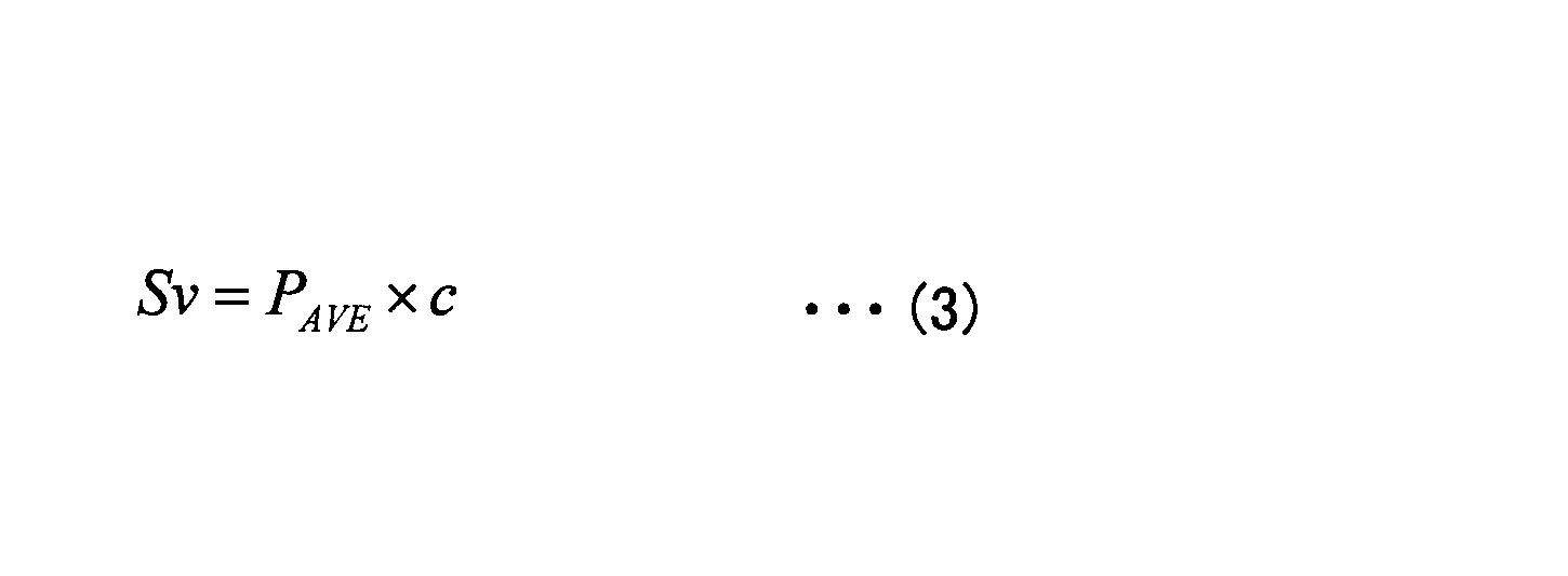
ここで基準値Svは、式(3)に示すように、ピークの高さの平均値PAVEの定数c倍で定義される。式(3)における定数cは経験的に0.7程度に設定することが好ましい。ピークの高さは、瞬きの様子やドップラーセンサ10からの距離によって変化するが、長時間観測の場合は基準値Svの値を更新することで対応することができる。
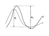
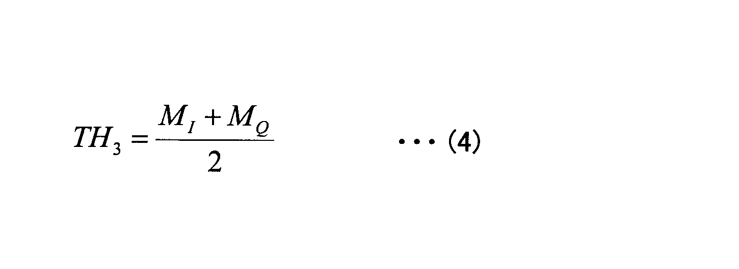
そして、図8に示すように、I信号及びQ信号のそれぞれにおいて、0.2秒の時間幅内における電圧値の高低差MI及びMQを求める。高低差MI及びMQが共に式(4)により求まる第3閾値TH3以上の場合、表面積の大きな動きによってドップラーセンサ10の出力信号(I信号及びQ信号)が大きくなったと考えられ、誤検出(体動による信号成分)と判定できる。
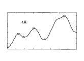
体動による信号波形は極大点と極小点を多く持つ傾向にある。そこで、平滑化したI信号及びQ信号から得られた極大点と極小点の合計数が共に第4閾値TH4以上の場合は、その信号が誤検出(体動による信号)であると判定する。ここでは、一例として第4閾値TH4を5点とするが、これには限定されない。
第4閾値TH4を5点とした場合、例えば、図9Aでは極小点が1点であるから瞬きであると判定し、図9Bでは極大点と極小点の合計数が5点であるから体動であると判定する。
以上をまとめると、ステップS106において、ピーク高判定部241の判定でピークの高さが基準値Sv以下の信号、電圧高低差判定部242の判定で高低差MI及びMQが共に第3閾値TH3以上の信号、及び位相変化判定部243の判定で平滑化したI信号及びQ信号から得られた極大点と極小点の合計数が共に第4閾値TH4以上の信号がFPとして除外される。
そして、ステップS103において第1閾値TH1以上の信号成分、及びステップS105においてピークが検出された信号成分のうち、ステップS106でFPとして除外された信号成分を除いた残りの信号成分が瞬きと判定される。ここで、ピーク高判定部241の判定、電圧高低差判定部242の判定、及び位相変化判定部243の判定の処理順は任意に決定して構わない。
なお、ステップS101~S106の全てを実行する必要はなく、最低限ステップS101、S103、及びS106(ピーク高判定、電圧高低差判定、位相変化判定の何れか1つ)を実行することで、従来よりも瞬き検出の精度を向上できる。
但し、ステップS104及びS105を実行することで瞬き検出の精度を向上できる。又、ステップS106でピーク高判定、電圧高低差判定、位相変化判定の何れか2つを実行することで更に瞬き検出の精度を向上でき、3つ全てを実行することで更に瞬き検出の精度を向上できる。
このように、本実施の形態に係る瞬き検出システム1では、CA-CFAR検出部21によるCA-CFAR検出において第1閾値TH1を動的に決定することで、身体の揺らぎや雑音に対するロバスト性を高め、瞬きの検出漏れ(FN)を低減することができる。又、瞬き波形の特徴に基づく瞬き判定部24の処理により、誤って瞬きと検出しやすい微かな体動を除外し、誤検出(FP)の数を低減させることができる。そして、これらを組み合わせることで、機械学習が不要で高精度な瞬き検出が可能となる。
[実施例]
ドップラーセンサ10を用いて3種類の実験を行った。実験の諸元を表1に示す。
ドップラーセンサ10を用いて3種類の実験を行った。実験の諸元を表1に示す。

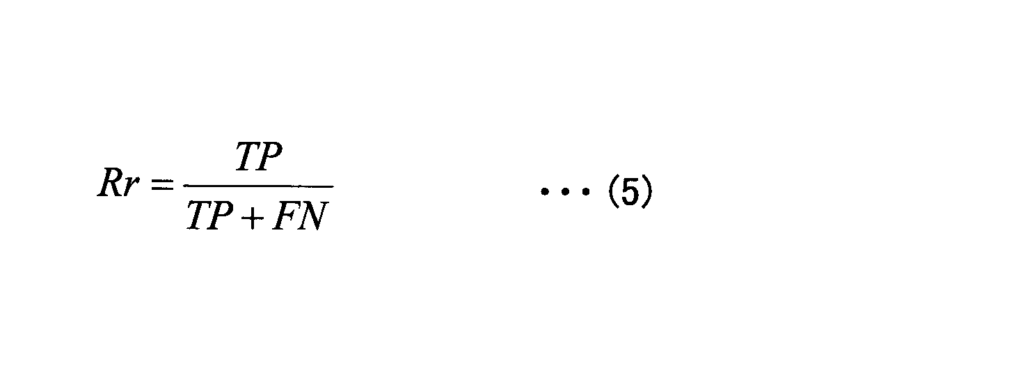
又、評価には検出率Rrと適合率Prを用いる。検出率Rrは実際の瞬きのうち検出できた瞬きの割合を、適合率Prは瞬きと検出したうちの正解の割合を示し、式(5)及び式(6)で定義される。式(5)及び式(6)において、TPは正しく検出できた瞬きの数、FNは検出漏れした瞬きの数、FPは誤って瞬きとして検出した数を示している。
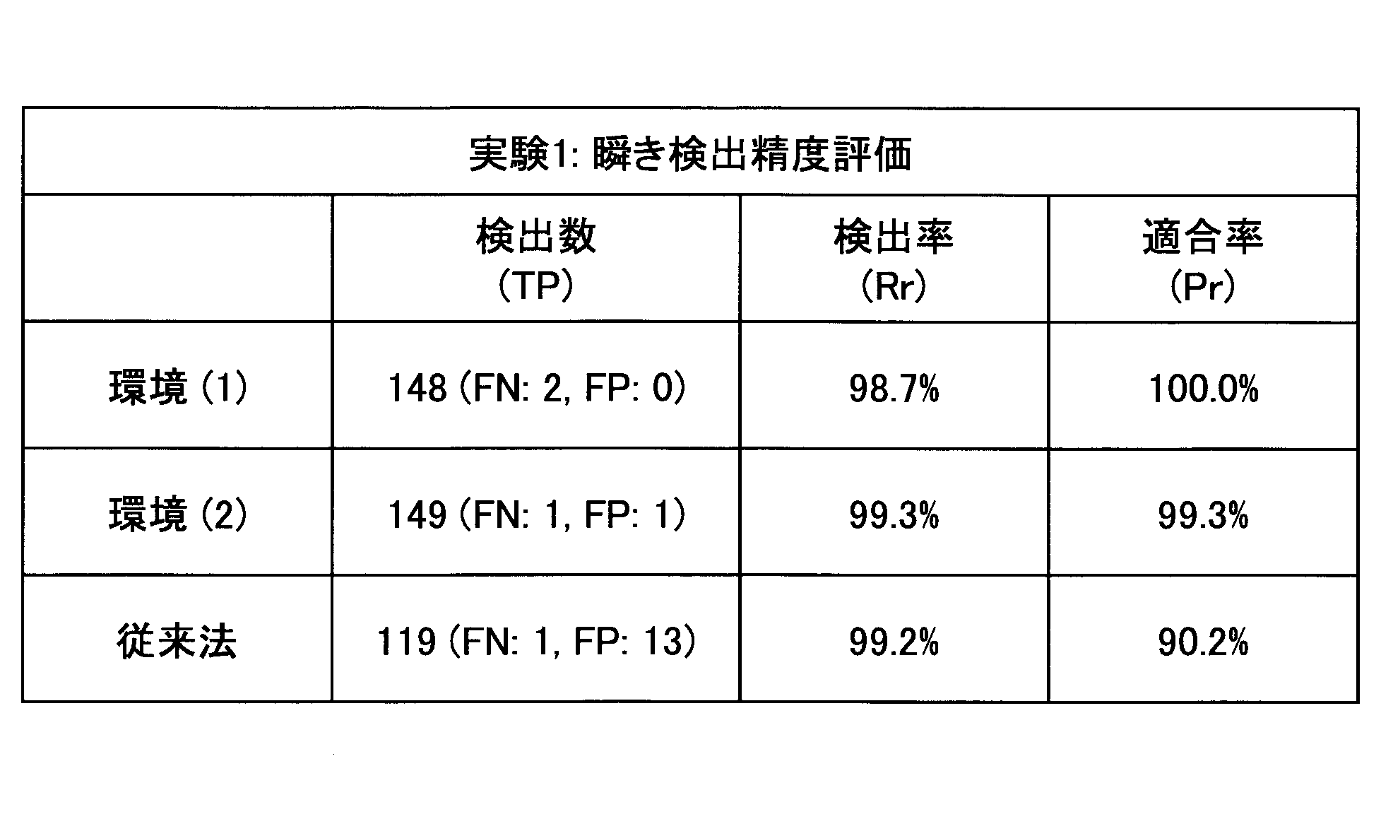
一方、提案法は検出率Rr、適合率Prともに約99%の高い瞬き検出精度を達成した。提案法では、瞬き信号の検出にCA-CFAR検出を適用することで身体の揺らぎや雑音に対するロバスト性を高めたことでFPを低減した。更に、瞬き波形の特徴に基づく瞬き判定部24の処理により、瞬きとして誤検出しやすい微かな体動を除外し、FPを低減した。このように、提案法が従来法と比較して瞬き検出の精度を向上できることが確認された。
次に、実験2の結果を表3に示す。
なお、この結果から、判定過程における各パラメータを複数の被験者に基づいて設定することで、適合率Prが更に向上すると考えられる。又、瞬き判定の前に、被験者毎にキャリブレーションを行い、被験者毎に各パラメータを微調整することで、適合率Prが更に向上すると考えられる。このキャリブレーションは、従来法のような大掛かりな学習とは異なり、極短時間で各パラメータを微調整できる。
最後に、実験3の結果を表4に示す。

以上の実験結果から、提案法のようにCA-CFAR検出部21によるCA-CFAR検出と瞬き判定部24によるFP除外処理とを組み合わせることで、TPの数を増加させつつFPの数を低減させることが可能となり、検出率Rr及び適合率Prが何れも約99%である高精度の瞬き検出を実現できることがわかった。
以上、好ましい実施の形態等について詳説したが、上述した実施の形態等に制限されることはなく、特許請求の範囲に記載された範囲を逸脱することなく、上述した実施の形態等に種々の変形及び置換を加えることができる。
本国際出願は2016年2月26日に出願した日本国特許出願2016-036467号に基づく優先権を主張するものであり、日本国特許出願2016-036467号の全内容を本国際出願に援用する。
1 瞬き検出システム
10 ドップラーセンサ
20 信号処理部
21 CA-CFAR検出部
22 体動検出部
23 ピーク検出部
24 瞬き判定部
241 ピーク高判定部
242 電圧高低差判定部
243 位相変化判定部
10 ドップラーセンサ
20 信号処理部
21 CA-CFAR検出部
22 体動検出部
23 ピーク検出部
24 瞬き判定部
241 ピーク高判定部
242 電圧高低差判定部
243 位相変化判定部
Claims (10)
- ドップラー信号を得るドップラーセンサと、
前記ドップラー信号の振幅信号を求め、前記振幅信号を時間軸方向に連続する複数のセルに分割し、注目するセルに隣接しない前後のセルの振幅値に基づいて第1閾値を決定し、前記注目するセルにおいて前記第1閾値以上の信号成分を検出する第1検出部と、
瞬き波形の特徴に基づいて、前記第1閾値以上の信号成分の中から誤検出を除去し、残りの信号成分を瞬きと判定する瞬き判定部と、を有する瞬き検出システム。 - 前記振幅信号を平滑化した振幅信号を生成し、前記平滑化した振幅信号と第2閾値とを比較し、前記第2閾値以下の信号成分を検出する第2検出部と、
前記第2閾値以下の信号成分のピーク検出を行うピーク検出部と、を有し、
前記瞬き判定部は、瞬き波形の特徴に基づいて、前記第1閾値以上の信号成分の中から誤検出を除去すると共に、前記ピーク検出部で検出されたピークの中から誤検出を除去し、それぞれの残りの信号成分を瞬きと判定する請求項1に記載の瞬き検出システム。 - 前記瞬き判定部は、前記第1閾値以上の信号成分に含まれるピークの高さ及び前記ピーク検出部で検出されたピークの高さと基準値とをそれぞれ比較し、前記ピークの高さが前記基準値以下の部分を誤検出と判定するピーク高判定部を備えている請求項2に記載の瞬き検出システム。
- 前記瞬き判定部は、前記ドップラー信号を構成するI信号及びQ信号のそれぞれの電圧値の高低差を求め、前記高低差が共に第3閾値以上の場合に誤検出と判定する電圧高低差判定部を備えている請求項1に記載の瞬き検出システム。
- 前記瞬き判定部は、前記ドップラー信号を構成するI信号及びQ信号のそれぞれの電圧値の極大点と極小点の合計数を求め、前記合計数が共に第4閾値以上の場合に誤検出と判定する位相変化判定部を備えている請求項1に記載の瞬き検出システム。
- ドップラーセンサで被験者からの反射波を受信してドップラー信号を得る第1ステップと、
前記ドップラー信号の振幅信号を求め、前記振幅信号を時間軸方向に連続する複数のセルに分割し、注目するセルに隣接しない前後のセルの振幅値に基づいて第1閾値を決定し、前記注目するセルにおいて前記第1閾値以上の信号成分を検出する第2ステップと、
瞬き波形の特徴に基づいて、前記第1閾値以上の信号成分の中から誤検出を除去し、残りの信号成分を瞬きと判定する第3ステップと、を有する瞬き検出方法。 - 前記振幅信号を平滑化した振幅信号を生成し、前記平滑化した振幅信号と第2閾値とを比較し、前記第2閾値以下の信号成分を検出する第4ステップと、
前記第2閾値以下の信号成分のピーク検出を行う第5ステップと、を有し、
前記第3ステップでは、瞬き波形の特徴に基づいて、前記第1閾値以上の信号成分の中から誤検出を除去すると共に、前記第5ステップで検出されたピークの中から誤検出を除去し、それぞれの残りの信号成分を瞬きと判定する請求項6に記載の瞬き検出方法。 - 前記第3ステップは、前記第1閾値以上の信号成分に含まれるピークの高さ及び前記第5ステップで検出されたピークの高さと基準値とをそれぞれ比較し、前記ピークの高さが前記基準値以下の部分を誤検出と判定するステップを備えている請求項7に記載の瞬き検出方法。
- 前記第3ステップは、前記ドップラー信号を構成するI信号及びQ信号のそれぞれの電圧値の高低差を求め、前記高低差が共に第3閾値以上の場合に誤検出と判定するステップを備えている請求項6に記載の瞬き検出方法。
- 前記第3ステップは、前記ドップラー信号を構成するI信号及びQ信号のそれぞれの電圧値の極大点と極小点の合計数を求め、前記合計数が共に第4閾値以上の場合に誤検出と判定するステップを備えている請求項6に記載の瞬き検出方法。
Applications Claiming Priority (2)
| Application Number | Priority Date | Filing Date | Title |
|---|---|---|---|
| JP2016-036467 | 2016-02-26 | ||
| JP2016036467A JP2017148447A (ja) | 2016-02-26 | 2016-02-26 | 瞬き検出システム、瞬き検出方法 |
Publications (1)
| Publication Number | Publication Date |
|---|---|
| WO2017146249A1 true WO2017146249A1 (ja) | 2017-08-31 |
Family
ID=59686304
Family Applications (1)
| Application Number | Title | Priority Date | Filing Date |
|---|---|---|---|
| PCT/JP2017/007318 Ceased WO2017146249A1 (ja) | 2016-02-26 | 2017-02-27 | 瞬き検出システム、瞬き検出方法 |
Country Status (2)
| Country | Link |
|---|---|
| JP (1) | JP2017148447A (ja) |
| WO (1) | WO2017146249A1 (ja) |
Cited By (1)
| Publication number | Priority date | Publication date | Assignee | Title |
|---|---|---|---|---|
| CN116299436A (zh) * | 2023-03-28 | 2023-06-23 | 中山艾朗格科技有限公司 | 3.07毫米波雷达准确检测人体眨眼动作的检测方法 |
Citations (1)
| Publication number | Priority date | Publication date | Assignee | Title |
|---|---|---|---|---|
| JP2015213634A (ja) * | 2014-05-12 | 2015-12-03 | 学校法人慶應義塾 | 瞬き検出システムおよび方法 |
-
2016
- 2016-02-26 JP JP2016036467A patent/JP2017148447A/ja active Pending
-
2017
- 2017-02-27 WO PCT/JP2017/007318 patent/WO2017146249A1/ja not_active Ceased
Patent Citations (1)
| Publication number | Priority date | Publication date | Assignee | Title |
|---|---|---|---|---|
| JP2015213634A (ja) * | 2014-05-12 | 2015-12-03 | 学校法人慶應義塾 | 瞬き検出システムおよび方法 |
Non-Patent Citations (1)
| Title |
|---|
| CHIHIRO TAMBA: "Improvement of Blink Detection Using a Doppler Sensor Based on CFAR Processing", IEICE TECHNICAL REPORT, vol. 115, 22 February 2016 (2016-02-22), pages 69 - 74, XP033058611 * |
Cited By (1)
| Publication number | Priority date | Publication date | Assignee | Title |
|---|---|---|---|---|
| CN116299436A (zh) * | 2023-03-28 | 2023-06-23 | 中山艾朗格科技有限公司 | 3.07毫米波雷达准确检测人体眨眼动作的检测方法 |
Also Published As
| Publication number | Publication date |
|---|---|
| JP2017148447A (ja) | 2017-08-31 |
Similar Documents
| Publication | Publication Date | Title |
|---|---|---|
| JP6406171B2 (ja) | 瞬目検知装置 | |
| CN107041743B (zh) | 一种心电信号实时r波检测方法 | |
| EP2777485A1 (en) | Signal processor, signal processing method, and signal processing program | |
| US9936919B2 (en) | Devices, systems, and methods for determining heart rate of a subject from noisy electrocardiogram data | |
| CN107714025B (zh) | 分类ecg信号 | |
| JP6645926B2 (ja) | 生体信号処理方法および装置 | |
| JP6652655B2 (ja) | 心拍検出方法および心拍検出装置 | |
| KR102007011B1 (ko) | 심전도 신호로부터 중요 포인트를 검출하는 장치 및 방법 | |
| US20170281021A1 (en) | Heartbeat detection method and heartbeat detection device | |
| JP6338445B2 (ja) | 瞬き検出システムおよび方法 | |
| US20240249554A1 (en) | Method and device for determining visual fatigue occurrence section | |
| KR20200024518A (ko) | 모바일 환경에서 심전도 r 피크를 검출하기 위한 방법 및 이를 구현하기 위한 시스템 | |
| WO2019241407A1 (en) | Predicting atrial fibrillation or stroke using p-wave analysis | |
| JP6779518B2 (ja) | 生体信号検出システム、生体信号検出方法 | |
| Yousefi et al. | Exploiting error-related potentials in cognitive task based BCI | |
| CN114795241A (zh) | 一种心电信号的噪声检测方法及系统 | |
| JP2012000280A (ja) | 脳波推定装置、脳波推定方法及びプログラム | |
| US10750969B2 (en) | Heartbeat detection method and heartbeat detection device | |
| JP2017148447A (ja) | 瞬き検出システム、瞬き検出方法 | |
| JP6706996B2 (ja) | 生体信号処理装置、異常判別方法およびプログラム | |
| Tun et al. | Analysis of computer aided identification system for ECG characteristic points | |
| CA3177890A1 (en) | Biological signal processing device, watching system, and watching method | |
| US20180271449A1 (en) | Heartbeat detection system and heartbeat detection method | |
| WO2020242334A1 (en) | System and method of automated electrocardiogram analysis and interpretation | |
| JP6221346B2 (ja) | 物体変位検知装置、及び物体変位検知方法 |
Legal Events
| Date | Code | Title | Description |
|---|---|---|---|
| NENP | Non-entry into the national phase |
Ref country code: DE |
|
| 121 | Ep: the epo has been informed by wipo that ep was designated in this application |
Ref document number: 17756683 Country of ref document: EP Kind code of ref document: A1 |
|
| 122 | Ep: pct application non-entry in european phase |
Ref document number: 17756683 Country of ref document: EP Kind code of ref document: A1 |