WO2017145565A1 - 投写型表示装置、投写表示方法、及び、投写表示プログラム - Google Patents
投写型表示装置、投写表示方法、及び、投写表示プログラム Download PDFInfo
- Publication number
- WO2017145565A1 WO2017145565A1 PCT/JP2017/001145 JP2017001145W WO2017145565A1 WO 2017145565 A1 WO2017145565 A1 WO 2017145565A1 JP 2017001145 W JP2017001145 W JP 2017001145W WO 2017145565 A1 WO2017145565 A1 WO 2017145565A1
- Authority
- WO
- WIPO (PCT)
- Prior art keywords
- information
- projection display
- image data
- driver
- projection
- Prior art date
- Legal status (The legal status is an assumption and is not a legal conclusion. Google has not performed a legal analysis and makes no representation as to the accuracy of the status listed.)
- Ceased
Links
Images





Classifications
-
- B—PERFORMING OPERATIONS; TRANSPORTING
- B60—VEHICLES IN GENERAL
- B60K—ARRANGEMENT OR MOUNTING OF PROPULSION UNITS OR OF TRANSMISSIONS IN VEHICLES; ARRANGEMENT OR MOUNTING OF PLURAL DIVERSE PRIME-MOVERS IN VEHICLES; AUXILIARY DRIVES FOR VEHICLES; INSTRUMENTATION OR DASHBOARDS FOR VEHICLES; ARRANGEMENTS IN CONNECTION WITH COOLING, AIR INTAKE, GAS EXHAUST OR FUEL SUPPLY OF PROPULSION UNITS IN VEHICLES
- B60K35/00—Instruments specially adapted for vehicles; Arrangement of instruments in or on vehicles
- B60K35/10—Input arrangements, i.e. from user to vehicle, associated with vehicle functions or specially adapted therefor
-
- B—PERFORMING OPERATIONS; TRANSPORTING
- B60—VEHICLES IN GENERAL
- B60K—ARRANGEMENT OR MOUNTING OF PROPULSION UNITS OR OF TRANSMISSIONS IN VEHICLES; ARRANGEMENT OR MOUNTING OF PLURAL DIVERSE PRIME-MOVERS IN VEHICLES; AUXILIARY DRIVES FOR VEHICLES; INSTRUMENTATION OR DASHBOARDS FOR VEHICLES; ARRANGEMENTS IN CONNECTION WITH COOLING, AIR INTAKE, GAS EXHAUST OR FUEL SUPPLY OF PROPULSION UNITS IN VEHICLES
- B60K35/00—Instruments specially adapted for vehicles; Arrangement of instruments in or on vehicles
- B60K35/20—Output arrangements, i.e. from vehicle to user, associated with vehicle functions or specially adapted therefor
- B60K35/21—Output arrangements, i.e. from vehicle to user, associated with vehicle functions or specially adapted therefor using visual output, e.g. blinking lights or matrix displays
- B60K35/23—Head-up displays [HUD]
- B60K35/235—Head-up displays [HUD] with means for detecting the driver's gaze direction or eye points
-
- B—PERFORMING OPERATIONS; TRANSPORTING
- B60—VEHICLES IN GENERAL
- B60K—ARRANGEMENT OR MOUNTING OF PROPULSION UNITS OR OF TRANSMISSIONS IN VEHICLES; ARRANGEMENT OR MOUNTING OF PLURAL DIVERSE PRIME-MOVERS IN VEHICLES; AUXILIARY DRIVES FOR VEHICLES; INSTRUMENTATION OR DASHBOARDS FOR VEHICLES; ARRANGEMENTS IN CONNECTION WITH COOLING, AIR INTAKE, GAS EXHAUST OR FUEL SUPPLY OF PROPULSION UNITS IN VEHICLES
- B60K35/00—Instruments specially adapted for vehicles; Arrangement of instruments in or on vehicles
- B60K35/20—Output arrangements, i.e. from vehicle to user, associated with vehicle functions or specially adapted therefor
- B60K35/28—Output arrangements, i.e. from vehicle to user, associated with vehicle functions or specially adapted therefor characterised by the type of the output information, e.g. video entertainment or vehicle dynamics information; characterised by the purpose of the output information, e.g. for attracting the attention of the driver
-
- B—PERFORMING OPERATIONS; TRANSPORTING
- B60—VEHICLES IN GENERAL
- B60K—ARRANGEMENT OR MOUNTING OF PROPULSION UNITS OR OF TRANSMISSIONS IN VEHICLES; ARRANGEMENT OR MOUNTING OF PLURAL DIVERSE PRIME-MOVERS IN VEHICLES; AUXILIARY DRIVES FOR VEHICLES; INSTRUMENTATION OR DASHBOARDS FOR VEHICLES; ARRANGEMENTS IN CONNECTION WITH COOLING, AIR INTAKE, GAS EXHAUST OR FUEL SUPPLY OF PROPULSION UNITS IN VEHICLES
- B60K35/00—Instruments specially adapted for vehicles; Arrangement of instruments in or on vehicles
- B60K35/50—Instruments characterised by their means of attachment to or integration in the vehicle
-
- G—PHYSICS
- G01—MEASURING; TESTING
- G01C—MEASURING DISTANCES, LEVELS OR BEARINGS; SURVEYING; NAVIGATION; GYROSCOPIC INSTRUMENTS; PHOTOGRAMMETRY OR VIDEOGRAMMETRY
- G01C21/00—Navigation; Navigational instruments not provided for in groups G01C1/00 - G01C19/00
- G01C21/26—Navigation; Navigational instruments not provided for in groups G01C1/00 - G01C19/00 specially adapted for navigation in a road network
- G01C21/34—Route searching; Route guidance
- G01C21/36—Input/output arrangements for on-board computers
-
- G—PHYSICS
- G02—OPTICS
- G02B—OPTICAL ELEMENTS, SYSTEMS OR APPARATUS
- G02B27/00—Optical systems or apparatus not provided for by any of the groups G02B1/00 - G02B26/00, G02B30/00
- G02B27/01—Head-up displays
-
- G—PHYSICS
- G08—SIGNALLING
- G08G—TRAFFIC CONTROL SYSTEMS
- G08G1/00—Traffic control systems for road vehicles
- G08G1/16—Anti-collision systems
-
- G—PHYSICS
- G09—EDUCATION; CRYPTOGRAPHY; DISPLAY; ADVERTISING; SEALS
- G09F—DISPLAYING; ADVERTISING; SIGNS; LABELS OR NAME-PLATES; SEALS
- G09F9/00—Indicating arrangements for variable information in which the information is built-up on a support by selection or combination of individual elements
-
- H—ELECTRICITY
- H04—ELECTRIC COMMUNICATION TECHNIQUE
- H04N—PICTORIAL COMMUNICATION, e.g. TELEVISION
- H04N5/00—Details of television systems
- H04N5/74—Projection arrangements for image reproduction, e.g. using eidophor
Definitions
- the present invention relates to a projection display device, a projection display method, and a projection display program.
- windshields or combiners placed near windshields are used as screens to project light and display images.
- a vehicle-mounted HUD Head-up Display
- an image based on light projected from the HUD can be visually recognized by the driver as a real image on the screen or as a virtual image in front of the screen.
- the HUD described in Patent Document 1 makes the driver effectively recognize the danger ahead of the automobile by determining the danger level in the running state of the automobile and displaying an animation according to the danger level.
- the HUD described in Patent Document 2 displays the animation for an icon for instructing the traveling direction of the automobile, thereby effectively allowing the driver to recognize the traveling direction.
- JP 2014-10800 A Japanese Patent Laid-Open No. 2015-69656
- Patent Document 1 and Patent Document 2 by performing animation display or the like, it is possible to guide the driver's line of sight and allow the driver to effectively recognize desired information. However, if such a display that attracts the driver's consciousness is continued for a long time, the driver may be distracted by the display, which may hinder driving. Patent Documents 1 and 2 do not consider such problems.
- the present invention has been made in view of the above circumstances, and can provide a projection display device, a projection display method, and a projection display that can allow a driver to recognize necessary information without causing any trouble in driving a vehicle.
- the purpose is to provide a program.
- the projection display device spatially modulates light emitted from a light source based on input image data, and projects the image light obtained by the spatial modulation onto a projection surface of a vehicle.
- a projection display unit for displaying an image based on the data, and image data including information indicating that the above condition is satisfied when a predetermined condition regarding the operating condition and / or driving condition of the vehicle is satisfied.
- an information recognition determination unit that determines whether or not the driver of the vehicle has recognized the information in a state where an image based on the image data including the information is displayed by the projection display unit.
- the input unit inputs image data excluding the information to the projection display unit when it is determined that the information is recognized by the driver. is there.
- the projection display method of the present invention spatially modulates light emitted from a light source based on input image data, and projects the image light obtained by the spatial modulation onto a projection surface in a vehicle, thereby the image data.
- an information recognition determination step for determining whether or not the driver of the vehicle has recognized the information in a state where an image based on image data including the information is displayed by the projection display unit, In the input step, when it is determined that the information is recognized by the driver, image data excluding the information is input to the projection display unit. Is.
- the projection display program of the present invention spatially modulates light emitted from a light source on the basis of input image data, and projects the image light obtained by the spatial modulation onto a projection surface of a vehicle.
- An information recognition determination step for determining whether or not the driver of the vehicle has recognized the information in a state where an image based on the image data including the information is displayed by the projection display unit. In the input step, when it is determined that the information is recognized by the driver, Image data excluding information is input to the projection display unit.
- a projection display device a projection display method, and a projection display program that allow a driver to recognize necessary information without hindering driving of a vehicle.
- FIG. 6 is a diagram illustrating an example of displaying an image based on image light projected on the projection plane 2. It is a flowchart for demonstrating the modification of operation
- FIG. 6 shows the indoor structure of the motor vehicle which mounts HUD200 which is a modification of HUD100 shown in FIG.
- FIG. 6 is a schematic diagram which shows the detailed structure of the control unit 4 of HUD200 shown in FIG.
- FIG. 1 is a diagram showing an indoor configuration of an automobile equipped with a HUD 100 which is an embodiment of the projection display device of the present invention.
- the HUD 100 is mounted on an automobile, and a part of the windshield 1 of the automobile is a projection plane 2.
- the image light projected on the projection plane 2 enables a driver of the automobile to visually recognize a virtual image or a real image. It is.
- the HUD 100 can be used by being mounted on a vehicle such as a train, heavy equipment, construction equipment, an aircraft, a ship, or an agricultural machine in addition to an automobile.
- a vehicle such as a train, heavy equipment, construction equipment, an aircraft, a ship, or an agricultural machine in addition to an automobile.
- the HUD 100 is built in the dashboard 3 of the automobile.
- the dashboard 3 is a member that incorporates interior parts including instruments for notifying information necessary for traveling such as a speedometer, tachometer, fuel meter, water temperature meter, or distance meter of an automobile.
- the HUD 100 includes a control unit 4 including a light source and a light modulation element that spatially modulates light emitted from the light source based on image data, and image light spatially modulated by the light modulation element of the control unit 4.
- a diffusing member 5, a reflecting mirror 6, and a concave mirror 7 constituting a projection unit that projects onto the projection surface 2 are provided.
- an imaging unit 9 is provided in the rearview mirror 8 above the windshield 1.
- the diffusion member 5 is a member that diffuses the image light spatially modulated by the light modulation element of the control unit 4 to form a surface light source.
- a micro mirror array having a fine structure on the surface a diffusing mirror, a reflection holographic diffuser, or the like is used.
- the reflection mirror 6 reflects the image light diffused by the diffusion member 5.
- the concave mirror 7 magnifies and reflects the image light reflected by the reflecting mirror 6 and projects it onto the projection plane 2.
- the projection surface 2 of the windshield 1 is processed so as to reflect the image light projected from the concave mirror 7 in the direction of the driver's eyes.
- the HUD 100 is configured to project image light onto the windshield 1 in the vehicle, but may be configured to project image light onto a combiner disposed in the vicinity of the windshield 1.
- the combiner constitutes the projection plane.
- the combiner there are a type installed near the dashboard 3 and a sun visor type installed near the ceiling.
- the HUD 100 is installed not near the dashboard 3 but near the ceiling of the automobile.
- An automobile driver can visually recognize information such as icons or characters for assisting driving by a virtual image based on image light projected on the projection plane 2 and reflected on the projection plane 2.
- the projection surface 2 has a function of transmitting light from the outside (outside the vehicle) of the windshield 1. For this reason, the driver
- the imaging unit 9 attached to the rearview mirror 8 images the face of the driver of the car and is connected to the control unit 4 by wire or wirelessly. Captured image data obtained by imaging the driver's face by the imaging unit 9 is transferred to the control unit 4 by wire or wirelessly.
- the imaging unit 9 may be attached to a place other than the rearview mirror 8, for example, the dashboard 3 or the like.
- the imaging unit 9 may be provided exclusively for the HUD 100 or may be used for other purposes such as driving assistance.
- FIG. 2 is a schematic diagram showing a detailed configuration of the control unit 4 of the HUD 100 shown in FIG.
- the control unit 4 includes a light source unit 40, a light modulation element 44, a drive unit 45 that drives the light modulation element 44, and a system control unit 60 that controls the entire HUD 100.
- the system control unit 60 is configured mainly by one or a plurality of processors, and is a non-transitory recording medium ROM (Read Only Memory) in which a program executed by the processor is stored, and recording as a work memory. It includes a medium RAM (Random Access Memory) and the like, and operates by loading a program stored in a recording medium.
- ROM Read Only Memory
- RAM Random Access Memory
- the light source unit 40 includes a light source controller 40A, an R light source 41r that is a red light source that emits red light, a G light source 41g that is a green light source that emits green light, and a B light source that is a blue light source that emits blue light. 41b, dichroic prism 43, collimator lens 42r provided between R light source 41r and dichroic prism 43, collimator lens 42g provided between G light source 41g and dichroic prism 43, B light source 41b and dichroic prism 43, a collimator lens 42b provided between the two.
- the R light source 41r, the G light source 41g, and the B light source 41b constitute a light source of the HUD 100.
- the dichroic prism 43 is an optical member for guiding light emitted from each of the R light source 41r, the G light source 41g, and the B light source 41b to the same optical path.
- the dichroic prism 43 transmits the red light collimated by the collimator lens 42 r and emits the red light to the light modulation element 44.
- the dichroic prism 43 reflects the green light that has been collimated by the collimator lens 42 g and emits it to the light modulation element 44. Further, the dichroic prism 43 reflects the blue light that has been collimated by the collimator lens 42 b and emits it to the light modulation element 44.
- the optical member having the function of guiding light to the same optical path is not limited to the dichroic prism. For example, a cross dichroic mirror may be used.
- Each of the R light source 41r, the G light source 41g, and the B light source 41b uses a light emitting element such as a laser or an LED (Light Emitting Diode).
- the light source of the HUD 100 is not limited to three examples of the R light source 41r, the G light source 41g, and the B light source 41b, and may be configured by one, two, or four or more light sources.
- the light source control unit 40A controls each of the R light source 41r, the G light source 41g, and the B light source 41b, and performs control to emit light from the R light source 41r, the G light source 41g, and the B light source 41b.
- the light modulation element 44 spatially modulates the light emitted from the R light source 41r, the G light source 41g, and the B light source 41b and emitted from the dichroic prism 43 based on image data input by the system control unit 60.
- LCOS Liquid crystal on silicon
- DMD Digital Micromirror Device
- MEMS Micro Electro Mechanical Systems
- a liquid crystal display element for example, LCOS (Liquid crystal on silicon), DMD (Digital Micromirror Device), MEMS (Micro Electro Mechanical Systems) element, or a liquid crystal display element can be used.
- the driving unit 45 drives the light modulation element 44 based on the image data input from the system control unit 60, and outputs image light (red image light, blue image light, and green image light) according to the image data.
- image light red image light, blue image light, and green image light
- the light is emitted from the light modulation element 44 to the diffusion member 5.
- the projection unit composed of the diffusing member 5, the reflecting mirror 6, and the concave mirror 7 shown in FIG. 1 is configured so that the image based on the image light projected on the projection surface 2 is displayed as a virtual image at a position in front of the windshield 1.
- the optical design is made so as to be visible.
- the optical design of the projection unit may be made so that an image based on the image light is visible to the driver as a real image on the windshield 1.
- the system control unit 60 controls the light source control unit 40A and the drive unit 45 to emit image light based on the image data from the control unit 4 to the diffusing member 5.
- the light source unit 40, the light modulation element 44, the drive unit 45, the diffusing member 5, the reflection mirror 6, and the concave mirror 7 convert the light emitted from the R light source 41 r, G light source 41 g, and B light source 41 b to the system control unit 60.
- the projection display unit is configured to perform spatial modulation based on the image data input from, project the image light obtained by the spatial modulation onto the projection plane 2 of the automobile, and display an image based on the image data.
- FIG. 3 is a functional block diagram of the system control unit 60 shown in FIG.
- the system control unit 60 includes a line-of-sight detection unit 61, an image data generation unit 62, an input unit 63, and an information recognition determination unit 64.
- a function of each unit in the system control unit 60 is realized by a control device such as one or a plurality of processors (CPU: Central Processing Unit) executing a program loaded in the memory.
- processors CPU: Central Processing Unit
- the line-of-sight detection unit 61, the image data generation unit 62, the input unit 63, and the information recognition determination unit 64 are configured by the processor executing a program stored in the ROM.
- This program includes a projection display program.
- the line-of-sight detection unit 61 acquires the captured image data transferred from the imaging unit 9, analyzes the acquired captured image data by image analysis processing, and detects the line of sight of the driver of the car.
- the line-of-sight detection unit 61 acquires the movement information of the driver's head by using, for example, an acceleration sensor or a gyro sensor mounted on the driver's head without using the imaging unit 9, and based on the movement information. Then, the line of sight of the driver of the car may be detected.
- the image data generation unit 62 generates image data including driving support information for supporting driving of a car.
- the driving support information is present information that always needs to be presented to the driver, such as the current time or the traveling speed of the car, and emergency information that needs to be presented to the driver only when a predetermined condition is satisfied. including.
- Predetermined conditions include, for example, that an object detection unit mounted on an automobile detects an obstacle such as a person, a windshield 1 cleaning solution measured by a meter mounted on the automobile, engine oil, gasoline, Or, it is determined that the position information of the vehicle detected by a GPS (Global Positioning System) receiver, etc., where the remaining amount of physical quantity that decreases with the operation of the vehicle such as a battery is less than the threshold, is in the vicinity of the right / left turn point.
- This is a condition relating to the operating state and / or driving state of the vehicle, such as being performed, or the traveling speed measured by the speedometer mounted on the vehicle exceeding a threshold value.
- Emergency information is information indicating that the above conditions are satisfied.
- the emergency information may be, for example, navigation information to a destination indicating that the vehicle is in the vicinity of a right / left turn point, warning information for warning the driver, or the like.
- Warning information includes information indicating the presence of obstacles, remaining amount information indicating that the remaining amount of a physical quantity such as cleaning liquid, engine oil, gasoline, or battery is less than a threshold, or information indicating that the speed is exceeded, etc. It is.
- the image data generation unit 62 generates image data including emergency information when the predetermined condition is satisfied.
- the input unit 63 inputs the image data generated by the image data generation unit 62 to the drive unit 45.
- the drive unit 45 drives the light modulation element 44 based on the image data input from the input unit 63 to project image light based on the image data onto the projection plane 2.
- the information recognition determination unit 64 determines whether or not the driver has recognized the presence information included in the image based on the image data in a state where image light based on the image data including the presence information is projected on the projection surface 2. Determine.
- the information recognition determination unit 64 determines, for example, whether or not the line of sight is within the projection range of the image light on the projection plane 2 from the direction of the driver's line of sight detected by the line of sight detection unit 61. The information recognition determination unit 64 determines that the emergency information projected on the projection plane 2 has been recognized when the line of sight is within the projection range.
- the information recognition determination unit 64 determines that the emergency information has been recognized when the driver's line of sight detected by the line of sight detection unit 61 overlaps with the emergency information projected on the projection surface 2. Also good.
- FIG. 4 is a flowchart for explaining the operation of the HUD 100 shown in FIG.
- a specific display example will be described with reference to FIG. Note that the processing shown in FIG. 4 is repeatedly executed while the HUD 100 is powered on.
- FIG. 5 is a diagram illustrating a display example of an image based on the image light projected on the projection plane 2.
- the image data generation unit 62 of the system control unit 60 generates image data including normal speed information such as an arrow icon for performing driving speed and navigation to a destination.
- the input unit 63 inputs the image data generated by the image data generation unit 62 to the drive unit 45 (step S0).
- the light modulation element 44 is driven, spatial modulation is performed on the light emitted from the light source unit 40, and the image is based on the image data including the resident information. (Screen 2A shown in FIG. 5) is displayed.
- speed information 101 and an arrow icon 102 are displayed as permanent information.
- Step S1 determines whether or not any one of the plurality of conditions listed above is satisfied (step S1), and when none of the conditions is satisfied. (Step S1: NO) returns the process to Step S0.
- step S1 When it is determined that any one of a plurality of conditions is satisfied (step S1: YES), the image data generation unit 62 of the system control unit 60 generates image data including the resident information and the emergency information. .
- the input unit 63 inputs this image data to the drive unit 45 of the light source unit 40 (step S2).
- the light modulation element 44 is driven based on the image data input to the drive unit 45, spatial modulation is performed on the light emitted from the light source unit 40, and the image data includes the resident information and the resident information. Is displayed (screen 2B shown in FIG. 5).
- speed information 101 and an arrow icon 102 are displayed as permanent information, and a warning icon 103 for notifying a warning is displayed as emergency information.
- the warning icon 103 is information indicating the presence of an obstacle, information indicating that the remaining amount of the physical quantity is less than a threshold value, information indicating that the vehicle has reached the right or left turn point, or that the speed is exceeded. Information or the like. These pieces of information may be displayed as a still image, but can be effectively recognized by the driver by being displayed as an animation.
- step S2 the line-of-sight detection unit 61 of the system control unit 60 detects the driver's line of sight (step S3).
- the information recognition determination unit 64 of the system control unit 60 determines whether or not the driver's line of sight has entered the image light projection range on the projection plane 2 based on the detection result by the line-of-sight detection unit 61 ( Step S4).
- the information recognition determination unit 64 of the system control unit 60 repeats the line-of-sight detection process in step S3 until it is determined that the driver's line of sight has entered the projection range.
- step S4 determines that the driver's line of sight is within the projection range
- step S5 determines that the driver's line of sight is within the projection range
- step S5 the image data generation unit 62 of the system control unit 60 generates image data excluding the emergency information (image data including only the permanent information). Then, the input unit 63 inputs the image data not including this emergency information to the drive unit 45 (step S6).
- the light modulation element 44 is driven according to the image data input to the drive unit 45, spatial modulation is performed on the light emitted from the light source unit 40, and an image based on the image data including the resident information (see FIG. Screen 2C) shown in FIG. 5 is displayed.
- the speed information 101 and the arrow icon 102 which are permanent information, are displayed, but the warning icon 103 is not displayed.
- step S6 the system control unit 60 again determines whether or not any one of the plurality of conditions is satisfied (step S7). If the determination in step S7 is no, the system control unit 60 returns the process to step S0.
- step S7 determines whether or not the content of the condition satisfied in step S7 satisfies the condition performed immediately before the determination process in step S7. It is determined whether or not the content of the condition determined to satisfy is satisfied (step S8).
- step S8 determines whether the emergency information has been notified. If the determination in step S8 is YES, that is, if the condition determined to be satisfied in step S1 is continuously satisfied), it can be determined that the emergency information has been notified.
- the control unit 60 returns the process to step S6.
- step S8 determines whether the emergency information needs to be newly notified. Therefore, the system control unit 60 returns the process to step S2.
- the system control unit 60 displays emergency information when a predetermined condition is satisfied, and inputs it to the drive unit 45 when it is determined that the driver has recognized the emergency information.
- the image data is switched to image data including only the resident information excluding the emergency information.
- the system control unit 60 of the HUD 100 determines that the emergency information has been recognized when a time that does not interfere with driving has elapsed since the driver's line of sight entered the image light projection range. May be. With this configuration, it is possible to improve the accuracy of determining whether or not the driver has recognized the emergency information.
- the system control unit 60 of the HUD 100 may determine that the emergency information is recognized when the driver's line of sight overlaps with the emergency information. In this case, the driver's line of sight is also present. It may be determined that the emergency information has been recognized when the state of overlapping with the information is continued for a time that does not hinder driving. With this configuration, it is possible to improve the accuracy of determining whether or not the driver has recognized the emergency information.
- the position where the obstacle exists at the time when the two most recent condition determination processes are performed. (For example, the difference between the position of the obstacle at the time of determination in step S1 and the position of the obstacle at the time of determination in step S7), and if this difference is less than the threshold, the content of the condition If the difference is equal to or greater than a threshold value, it may be determined that the content of the condition does not match.
- the warning information indicating the presence of the obstacle is displayed once and then the warning information is recognized and the warning information is not displayed, the warning information is separated from the obstacle. When another obstacle appears, warning information indicating the presence of this other obstacle is displayed. For this reason, the driver can be surely recognized by the driver, and safe driving can be supported.
- the emergency information is physical quantity remaining information
- FIG. 6 is a flowchart for explaining a modified example of the operation of the HUD 100 shown in FIG.
- the flowchart shown in FIG. 6 is the same as FIG. 4 except that step S9 and step S10 are added. Therefore, in FIG. 6, the same processes as those in FIG.
- step S8 determines whether or not the content of the condition that is continuously satisfied is “the remaining amount of the physical quantity such as gasoline is less than the threshold”. Determine (step S9). If the determination in step S9 is NO, the system control unit 60 returns the process to step S6.
- step S ⁇ b> 9 the system control unit 60 determines whether or not the elapsed time after the condition “the remaining amount of physical quantity is less than the threshold value” has reached a predetermined set value. Is determined (step S10). As this set value, a plurality of values such as a multiple of 20 minutes (20 minutes, 40 minutes, 60 minutes,%) May be set.
- step S10 determines whether the system control unit 60 is YES or not. If the determination in step S10 is YES, the system control unit 60 returns the process to step S2 and inputs image data including the remaining amount information to the drive unit 45. If the determination in step S10 is no, the system control unit 60 returns the process to step S6.
- the remaining amount information even if information indicating that the remaining amount of the physical quantity is less than the threshold value is displayed once and recognized by the driver and is not displayed, While the condition “being less than” is continuously satisfied, the remaining amount information is periodically redisplayed, for example. Even if the remaining amount information is recognized once, it may be forgotten over time. Thus, the remaining amount information is displayed again at a predetermined timing after being hidden, so that it becomes possible to inform the driver of the remaining amount shortage again.
- the system control unit 60 does not immediately hide the emergency information. For example, the system control unit 60 gradually decreases the display brightness of the emergency information and finally hides the emergency information.
- the emergency information display color is gradually lightened and finally hidden, or the emergency information blinks for a predetermined time and then disappears, or the emergency information is gradually reduced to the final Alternatively, it may be hidden.
- These display methods may be freely selectable by the driver. With such a configuration, display suitable for the driver's preference is possible. Also, emergency information can be erased in a natural way.
- Warning information as emergency information attracts the attention of the driver, so it is highly likely that the driver will be distracted by the display and hinder driving. For this reason, the effect acquired by HUD100 will bring about a remarkable effect, when emergency information is warning information.
- FIG. 7 is a diagram showing an indoor configuration of an automobile equipped with a HUD 200 that is a modification of the HUD 100 shown in FIG.
- FIG. 7 has the same configuration as that of FIG. 1 except that the imaging unit 9 is deleted and the operation unit 10 is added.
- the HUD 200 shown in FIG. 7 is the same as the HUD 100 except that the function of the system control unit 60 is different.
- the operation unit 10 includes a touch panel or buttons for inputting information to the system control unit 60 of the HUD 200.
- the operation unit 10 is provided in the vicinity of a portion of the automobile handle 11 where the driver's finger is placed.
- the driver When the driver confirms the emergency information displayed by the HUD 200, the driver inputs an operation signal indicating that the emergency information has been recognized to the system control unit 60 of the HUD 200 by pressing the operation unit 10. Can do.
- FIG. 8 is a schematic diagram showing a detailed configuration of the control unit 4 of the HUD 200 shown in FIG. In FIG. 8, the same components as those in FIG.
- the system control unit 60 of the HUD 200 illustrated in FIG. 8 receives the operation information from the operation unit 10 in a state where image data including the presence information and the emergency information is input to the drive unit 45.
- the image data including the emergency information is changed to image data including only the permanent information, and the changed image data is input to the drive unit 45.
- FIG. 9 is a functional block diagram of the system control unit 60 shown in FIG. 9, the same components as those in FIG. 3 are denoted by the same reference numerals.
- the system control unit 60 shown in FIG. 9 has the same configuration as that in FIG. 3 except that the line-of-sight detection unit 61 is not included.
- the information recognition determination unit 64 of the system control unit 60 illustrated in FIG. It is determined that emergency information is recognized.
- FIG. 10 is a flowchart for explaining the operation of the HUD 200 shown in FIG.
- the flowchart shown in FIG. 10 is the same as the flowchart shown in FIG. 4 except that step S3 is not included and step S4 is changed to step S11.
- step S11 the information recognition determination unit 64 of the system control unit 60 determines whether or not an operation signal is input from the operation unit 10.
- the information recognition determination unit 64 of the system control unit 60 stands by until an operation signal is input from the operation unit 10.
- step S5 the information recognition determination part 64 of the system control part 60 determines with the driver
- the HUD 200 shown in FIG. 7 determines that the emergency information has been recognized by the driver based on the operation signal input from the operation unit 10 operated by the driver. For this reason, it is possible to accurately determine whether or not the emergency information is recognized. Also with this configuration, necessary information can be presented to the driver without hindering the driving of the automobile.
- the driver can decide whether or not to hide the emergency information by his / her own intention. For this reason, for example, the remaining amount information is displayed so as not to be forgotten, and the navigation information is not displayed when it is confirmed.
- the operation unit 10 may be capable of inputting an operation signal to the system control unit 60 by gesture operation or voice.
- the information recognition determination unit 64 of the system control unit 60 of the HUD 100 accepts the input of the operation signal from the operation unit 10, it recognizes that the emergency information is recognized. Also good. That is, you may combine the structure of HUD100 and HUD200.
- the system control unit 60 hides the emergency information when the emergency information is recognized.
- the system control unit 60 maintains the display of the emergency information, for example, reduces the display brightness of the emergency information, reduces the display color of the emergency information, or blinks the emergency information.
- the display may be changed, the display size of the emergency information may be reduced, or the display position of the emergency information may be moved to the screen edge.
- the disclosed projection display device spatially modulates light emitted from a light source based on input image data, and projects the image light obtained by the spatial modulation onto a projection surface of a vehicle.
- a projection display unit for displaying an image based on the data, and image data including information indicating that the above condition is satisfied when a predetermined condition regarding the operating condition and / or driving condition of the vehicle is satisfied.
- an information recognition determination unit that determines whether or not the driver of the vehicle has recognized the information in a state where an image based on the image data including the information is displayed by the projection display unit.
- the input unit inputs image data excluding the information to the projection display unit when it is determined that the information is recognized by the driver. It is.
- the disclosed projection display device further includes a line-of-sight detection unit that detects the driver's line of sight, and the information recognition determination unit determines whether the driver has recognized the information based on the line of sight. To do.
- the driver when the signal is input from the operation unit for inputting a signal indicating that the information is recognized, the driver recognizes the information. It is determined that it has been recognized.
- the condition is that the remaining amount of the physical quantity that decreases with the operation of the vehicle is less than a threshold value, and the input unit has the remaining amount of the physical quantity less than the threshold value.
- Image data including information indicating that the remaining amount of the physical quantity is less than a threshold at a predetermined timing after inputting the image data excluding information indicating that to the projection display unit. Input.
- the information includes information for warning the driver.
- the projection surface is a windshield of the vehicle.
- the projection surface includes a combiner mounted on the vehicle.
- the disclosed projection display method spatially modulates light emitted from a light source based on input image data, and projects the image light obtained by the spatial modulation onto a projection surface of a vehicle, thereby the image data.
- an information recognition determination step for determining whether or not the driver of the vehicle has recognized the information in a state where an image based on image data including the information is displayed by the projection display unit, In the input step, when it is determined that the information is recognized by the driver, image data excluding the information is input to the projection display unit. Is.
- the disclosed projection display method further includes a line-of-sight detection step for detecting the driver's line of sight, and the information recognition determination step determines whether the driver has recognized the information based on the line of sight. Is.
- the driver recognizes the information when the signal is input from an operation unit for inputting a signal indicating that the information is recognized. It is determined that it was done.
- the condition is that the remaining amount of the physical quantity that decreases with the operation of the vehicle is less than a threshold value, and the remaining amount of the physical quantity is less than the threshold value in the input step.
- the image data including information indicating that the remaining amount of the physical quantity is less than the threshold is input to the projection display unit at a predetermined timing after the image data excluding information indicating the input is input to the projection display unit. To do.
- the information includes information for warning the driver.
- the projection surface is a windshield of the vehicle.
- the projection plane is a combiner mounted on the vehicle.
- the disclosed projection display program spatially modulates light emitted from a light source based on input image data, and projects the image light obtained by the spatial modulation onto a projection surface in a vehicle, thereby the image data.
- An information recognition determination step for determining whether or not the driver of the vehicle has recognized the information in a state where an image based on the image data including the information is displayed by the projection display unit. In the input step, when it is determined that the information is recognized by the driver, The image data excluding the information is input to the projection display unit.
- the present invention is particularly convenient and effective when installed in an automobile.
Landscapes
- Engineering & Computer Science (AREA)
- Chemical & Material Sciences (AREA)
- Combustion & Propulsion (AREA)
- Transportation (AREA)
- Mechanical Engineering (AREA)
- Physics & Mathematics (AREA)
- General Physics & Mathematics (AREA)
- Radar, Positioning & Navigation (AREA)
- Remote Sensing (AREA)
- Theoretical Computer Science (AREA)
- Multimedia (AREA)
- Signal Processing (AREA)
- Automation & Control Theory (AREA)
- Optics & Photonics (AREA)
- Instrument Panels (AREA)
Abstract
乗り物の運転に支障をきたすことなく、運転者に必要な情報を認知させることのできる投写型表示装置、投写表示方法、及び、投写表示プログラムを提供する。HUD100は、光源(41r、41g、41b)から出射される光を、入力された画像データに基づいて空間変調し、空間変調して得られた画像光を投写面2に投写して画像データに基づく画像を表示させる投写表示部と、警告情報を含む画像データを投写表示部に入力し、警告情報を含む画像データに基づく画像が投写表示部によって表示された状態で、運転者が警告情報を認知したか否かを判定し、運転者によって警告情報が認知されたと判定された場合には、警告情報を除外した画像データを投写表示部に入力するシステム制御部60と、を備える。
Description
本発明は、投写型表示装置、投写表示方法、及び、投写表示プログラムに関する。
自動車、電車、船舶、重機、航空機、又は、農作用機械等の乗り物内において、ウインドシールド、又は、ウインドシールドの付近に配置されるコンバイナをスクリーンとして用い、これに光を投写して画像を表示させる乗り物用のHUD(Head-up Display)が知られている(例えば特許文献1,2参照)。このHUDによれば、HUDから投写された光に基づく画像を、スクリーン上で実像として、又は、スクリーン前方において虚像として、運転者に視認させることができる。
特許文献1に記載のHUDは、自動車の走行状況における危険度を判定し、危険度に応じたアニメーション表示を行うことで、自動車前方の危険を効果的に運転者に認知させている。
特許文献2に記載のHUDは、自動車の進行方向を指示するためのアイコンをアニメーション表示させることで、この進行方向を効果的に運転者に認知させている。
特許文献1及び特許文献2のように、アニメーション表示等を行うことで、運転者の視線を誘導して、運転者に対して所望の情報を効果的に認知させることが可能である。しかし、こういった運転者の意識を惹く表示が長い間継続されると、運転者がその表示に気をとられてしまい、運転に支障が出る可能性がある。特許文献1,2ではこういった課題について考慮されていない。
本発明は、上記事情に鑑みてなされたものであり、乗り物の運転に支障をきたすことなく、運転者に必要な情報を認知させることができる投写型表示装置、投写表示方法、及び、投写表示プログラムを提供することを目的とする。
本発明の投写型表示装置は、光源から出射される光を、入力された画像データに基づいて空間変調し、上記空間変調して得られた画像光を乗り物における投写面に投写して上記画像データに基づく画像を表示させる投写表示部と、予め決められた乗り物の作動状況及び/又は運転状況に関する条件を満たす場合に、上記条件を満たしていることを示す情報を含む画像データを上記投写表示部に入力する入力部と、上記情報を含む画像データに基づく画像が上記投写表示部によって表示された状態において、上記乗り物の運転者が上記情報を認知したか否かを判定する情報認知判定部と、を備え、上記入力部は、上記運転者によって上記情報が認知されたと判定された場合に、上記情報を除外した画像データを上記投写表示部に入力するものである。
本発明の投写表示方法は、光源から出射される光を、入力された画像データに基づいて空間変調し、上記空間変調して得られた画像光を乗り物における投写面に投写して上記画像データに基づく画像を表示させる投写表示部に対し、予め決められた乗り物の作動状況及び/又は運転状況に関する条件を満たす場合に、上記条件を満たしていることを示す情報を含む画像データを入力する入力ステップと、上記情報を含む画像データに基づく画像が上記投写表示部によって表示された状態において、上記乗り物の運転者が上記情報を認知したか否かを判定する情報認知判定ステップと、を備え、上記入力ステップでは、上記運転者によって上記情報が認知されたと判定された場合に、上記情報を除外した画像データを上記投写表示部に入力するものである。
本発明の投写表示プログラムは、光源から出射される光を、入力された画像データに基づいて空間変調し、上記空間変調して得られた画像光を乗り物における投写面に投写して上記画像データに基づく画像を表示させる投写表示部に対し、予め決められた乗り物の作動状況及び/又は運転状況に関する条件を満たす場合に、上記条件を満たしていることを示す情報を含む画像データを入力する入力ステップと、上記情報を含む画像データに基づく画像が上記投写表示部によって表示された状態において、上記乗り物の運転者が上記情報を認知したか否かを判定する情報認知判定ステップと、をコンピュータに実行させるためのプログラムであって、上記入力ステップでは、上記運転者によって上記情報が認知されたと判定された場合に、上記情報を除外した画像データを上記投写表示部に入力するものである。
本発明によれば、乗り物の運転に支障をきたすことなく、運転者に必要な情報を認知させることができる投写型表示装置、投写表示方法、及び、投写表示プログラムを提供することができる。
以下、本発明の実施形態について図面を参照して説明する。
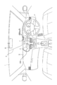
図1は、本発明の投写型表示装置の一実施形態であるHUD100を搭載した自動車の室内構成を示す図である。
HUD100は、自動車に搭載され、自動車のウインドシールド1の一部の範囲が投写面2とされ、投写面2に投写される画像光により、自動車の運転者によって虚像又は実像を視認可能にするものである。
HUD100は、自動車以外に、電車、重機、建機、航空機、船舶、又は、農作機械等の乗り物に搭載して用いることができる。
図1の例では、HUD100は、自動車のダッシュボード3に内蔵されている。ダッシュボード3は、自動車のスピードメータ、タコメータ、燃料計、水温計、又は、距離計等の走行に必要な情報を通知するための計器類等を含む内装部品を内蔵する部材である。
HUD100は、光源及びこの光源から出射される光を画像データに基づいて空間変調する光変調素子を含む制御ユニット4と、制御ユニット4の光変調素子により空間変調された画像光をウインドシールド1の投写面2に投写する投写部を構成する拡散部材5、反射ミラー6、及び、凹面鏡7と、を備える。HUD100が搭載される自動車には、ウインドシールド1上方のバックミラー8に、撮像部9が設けられている。
拡散部材5は、制御ユニット4の光変調素子により空間変調された画像光を拡散させて面光源化する部材である。拡散部材5は、表面に微細構造を有するマイクロミラーアレイ、拡散ミラー、又は、反射ホログラフィクディフューザー等が用いられる。
反射ミラー6は、拡散部材5で拡散された画像光を反射する。
凹面鏡7は、反射ミラー6で反射された画像光を拡大して反射し、投写面2に投写する。ウインドシールド1における投写面2は、凹面鏡7から投写された画像光を運転者の目の方向に反射するような加工がなされている。
HUD100は、乗り物内において、ウインドシールド1に対して画像光を投写する構成であるが、ウインドシールド1の付近に配置されるコンバイナに画像光を投写する構成であってもよい。この場合は、コンバイナが投写面を構成する。コンバイナとしては、ダッシュボード3付近に設置されるタイプと、天井付近に設置されるサンバイザタイプとがある。サンバイザタイプの場合、HUD100はダッシュボード3ではなく、自動車の天井付近に設置される。
自動車の運転者は、投写面2に投写され、投写面2で反射された画像光に基づく虚像により、運転を支援するためのアイコン又は文字等の情報を視認することができる。また、投写面2は、ウインドシールド1の外部(車外)からの光を透過する機能を持つ。このため、運転者は、凹面鏡7から投写された画像光に基づく虚像と外界の景色とが重畳された像を視認することができる。
バックミラー8に取り付けられた撮像部9は、自動車の運転者の顔を撮像するものであり、有線又は無線によって制御ユニット4と接続されている。撮像部9により運転者の顔を撮像して得られる撮像画像データは、有線又は無線によって制御ユニット4に転送される。
撮像部9は、バックミラー8以外の場所、例えばダッシュボード3等に取り付けてあってもよい。撮像部9は、HUD100のために専用に設けられたものであってもよいし、運転支援等の他の目的で使用されるものであってもよい。
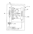
図2は、図1に示すHUD100の制御ユニット4の詳細構成を示す模式図である。
制御ユニット4は、光源ユニット40と、光変調素子44と、光変調素子44を駆動する駆動部45と、HUD100全体を統括制御するシステム制御部60と、を備える。
システム制御部60は、一つ又は複数のプロセッサを主体に構成されており、プロセッサの実行するプログラム等が記憶される非一時性の記録媒体ROM(Read Only Memory)、及び、ワークメモリとしての記録媒体RAM(Random Access Memory)等を含み、記録媒体に記憶されているプログラムをロードされることにより動作する。
光源ユニット40は、光源制御部40Aと、赤色光を出射する赤色光源であるR光源41rと、緑色光を出射する緑色光源であるG光源41gと、青色光を出射する青色光源であるB光源41bと、ダイクロイックプリズム43と、R光源41rとダイクロイックプリズム43の間に設けられたコリメータレンズ42rと、G光源41gとダイクロイックプリズム43の間に設けられたコリメータレンズ42gと、B光源41bとダイクロイックプリズム43の間に設けられたコリメータレンズ42bと、を備える。R光源41rとG光源41gとB光源41bはHUD100の光源を構成する。
ダイクロイックプリズム43は、R光源41r、G光源41g、及びB光源41bの各々から出射される光を同一光路に導くための光学部材である。ダイクロイックプリズム43は、コリメータレンズ42rによって平行光化された赤色光を透過させて光変調素子44に出射する。また、ダイクロイックプリズム43は、コリメータレンズ42gによって平行光化された緑色光を反射させて光変調素子44に出射する。さらに、ダイクロイックプリズム43は、コリメータレンズ42bによって平行光化された青色光を反射させて光変調素子44に出射する。光を同一光路に導く機能を持つ光学部材としては、ダイクロイックプリズムに限らない。例えば、クロスダイクロイックミラーを用いてもよい。
R光源41r、G光源41g、及びB光源41bは、それぞれ、レーザ又はLED(Light Emitting Diode)等の発光素子が用いられる。HUD100の光源は、R光源41rとG光源41gとB光源41bの3つの例に限らず、1つ、2つ、または4つ以上の光源によって構成されていてもよい。
光源制御部40Aは、R光源41r、G光源41g、及びB光源41bの各々を制御し、R光源41r、G光源41g、及び、B光源41bから光を出射させる制御を行う。
光変調素子44は、R光源41r、G光源41g、及び、B光源41bから出射され、ダイクロイックプリズム43から出射された光を、システム制御部60により入力される画像データに基づいて空間変調する。
光変調素子44としては、例えば、LCOS(Liquid crystal on silicon)、DMD(Digital Micromirror Device)、MEMS(Micro Electro Mechanical Systems)素子、又は、液晶表示素子等を用いることができる。
駆動部45は、システム制御部60から入力される画像データに基づいて光変調素子44を駆動し、画像データに応じた画像光(赤色画像光、青色画像光、及び、緑色画像光)を、光変調素子44から拡散部材5に出射させる。
図1に示した拡散部材5、反射ミラー6、及び、凹面鏡7から構成される投写部は、投写面2に投写された画像光に基づく画像が、ウインドシールド1前方の位置において虚像として運転者に視認可能となるように光学設計がなされている。この画像光に基づく画像が、ウインドシールド1において実像として運転者に視認可能となるように投写部の光学設計がなされていてもよい。
システム制御部60は、光源制御部40A及び駆動部45を制御して、画像データに基づく画像光を制御ユニット4から拡散部材5に出射させる。
光源ユニット40、光変調素子44、駆動部45、拡散部材5、反射ミラー6、及び、凹面鏡7は、R光源41r、G光源41g、及びB光源41bから出射される光を、システム制御部60から入力された画像データに基づいて空間変調し、空間変調して得られた画像光を自動車の投写面2に投写して、この画像データに基づく画像を表示させる投写表示部を構成する。
図3は、図2に示すシステム制御部60の機能ブロック図である。
システム制御部60は、視線検出部61と、画像データ生成部62と、入力部63と、情報認知判定部64と、を備える。例えば、1つ又は複数のプロセッサ(CPU :Central Processing Unit:中央処理装置)等の制御デバイスが、メモリにロードされたプログラムを実行することによりシステム制御部60内の各部における機能が実現される。
視線検出部61、画像データ生成部62、入力部63、及び、情報認知判定部64は、ROMに記憶されるプログラムをプロセッサが実行することによって構成される。このプログラムは、投写表示プログラムを含む。
視線検出部61は、撮像部9から転送されてきた撮像画像データを取得し、取得した撮像画像データを画像解析処理により解析して、自動車の運転者の視線を検出する。
視線検出部61は、撮像部9を利用せずに、例えば、運転者の頭部に装着された加速度センサ又はジャイロセンサ等により運転者の頭部の動き情報を取得し、この動き情報に基づいて自動車の運転者の視線を検出してもよい。
画像データ生成部62は、自動車の運転を支援するための運転支援情報を含む画像データを生成する。
運転支援情報は、現在時刻又は自動車の走行速度等の運転者へ常に提示が必要な常在情報と、予め決められた条件を満たす場合にのみ運転者への提示が必要となる非常在情報とを含む。
予め決められた条件とは、例えば、自動車に搭載された物体検知部が人物等の障害物を検知すること、自動車に搭載される計器により計測されるウインドシールド1の洗浄液、エンジンオイル、ガソリン、又は、バッテリ等の自動車の動作に伴って減少する物理量の残量が閾値未満となる、GPS(Global Positioning System)受信機等によって検知される自動車の位置情報が右左折のポイント付近にあると判断されること、又は、自動車に搭載される速度計により計測される走行速度が閾値を超えること等の、自動車の作動状況及び/又は運転状況に関する条件である。
非常在情報は、上記の条件を満たしていることを示す情報である。非常在情報は、例えば、右左折のポイント付近に来たこと等を示す目的地へのナビゲーション情報、又は、運転者に警告を行うための警告情報等であってもよい。
警告情報は、障害物の存在を示す情報、洗浄液、エンジンオイル、ガソリン、又はバッテリ等の物理量の残量が閾値未満であることを示す残量情報、又は、速度超過であることを示す情報等である。
画像データ生成部62は、上記の予め決められた条件を満たす場合には、非常在情報を含む画像データを生成する。
入力部63は、画像データ生成部62により生成された画像データを駆動部45に入力する。駆動部45は、入力部63から入力された画像データに基づいて光変調素子44を駆動することによって、この画像データに基づく画像光を投写面2に投写させる。
情報認知判定部64は、非常在情報を含む画像データに基づく画像光が投写面2に投写された状態で、この画像データに基づく画像に含まれる非常在情報を運転者が認知したか否かを判定する。
情報認知判定部64は、例えば、視線検出部61で検出された運転者の視線の方向から、投写面2における画像光の投写範囲に視線が入っているか否かを判定する。情報認知判定部64は、この投写範囲に視線が入っている場合に、投写面2に投写されている非常在情報が認知されたと判定する。
または、情報認知判定部64は、視線検出部61により検出された運転者の視線と投写面2に投写されている非常在情報とが重なった場合に、非常在情報が認知されたと判定してもよい。
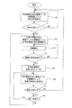
図4は、図1に示すHUD100の動作を説明するためのフローチャートである。図4の説明に当たり、図5を参照し、具体的な表示例も説明する。なお、図4に示す処理は、HUD100の電源がオンされている間、繰り返し実行される。図5は、投写面2に投写された画像光に基づく画像の表示例を示す図である。
まず、システム制御部60の画像データ生成部62は、自動車の走行速度と目的地へのナビゲーションを行うための矢印アイコン等の常在情報を含む画像データを生成する。そして、入力部63は、画像データ生成部62により生成された画像データを駆動部45に入力する(ステップS0)。
これにより、駆動部45に入力された画像データに基づいて、光変調素子44が駆動され、光源ユニット40から出射される光に対する空間変調が行われて、常在情報を含む画像データに基づく画像(図5に示す画面2A)が表示される。
画面2Aには、常在情報として、速度情報101及び矢印アイコン102が表示されている。
次に、システム制御部60の画像データ生成部62は、上記に挙げた複数の条件のいずれか1つの条件を満たすか否かを判定し(ステップS1)、いずれの条件も満たしていない場合には(ステップS1:NO)、ステップS0に処理を戻す。
システム制御部60の画像データ生成部62は、複数の条件のいずれか1つの条件を満たすと判定した場合(ステップS1:YES)には、常在情報と非常在情報を含む画像データを生成する。入力部63は、この画像データを光源ユニット40の駆動部45に入力する(ステップS2)。
これにより、駆動部45に入力された画像データに基づいて光変調素子44が駆動され、光源ユニット40から出射される光に対する空間変調が行われて、常在情報と非常在情報を含む画像データに基づく画像(図5に示す画面2B)が表示される。
画面2Bには、常在情報として速度情報101及び矢印アイコン102が表示され、非常在情報として警告を通知するための警告アイコン103が表示されている。
警告アイコン103は、障害物の存在を示す情報、上記の物理量の残量が閾値未満であることを示す情報、右左折のポイント付近に来たことを示す情報、又は、速度超過であることを示す情報等である。これらの情報は、静止画像として表示されてもよいが、アニメーション表示されることによって、運転者に効果的に認知させることができる。
ステップS2の後、システム制御部60の視線検出部61は、運転者の視線を検出する(ステップS3)。
次に、システム制御部60の情報認知判定部64は、視線検出部61による検出結果に基づいて、投写面2における画像光の投写範囲内に運転者の視線が入ったか否かを判定する(ステップS4)。
システム制御部60の情報認知判定部64は、運転者の視線が投写範囲に入ったと判定するまでステップS3の視線検出処理を繰り返す。
そして、システム制御部60の情報認知判定部64は、運転者の視線が投写範囲内に入ったと判定した場合(ステップS4:YES)には、投写面2に投写されている非常在情報(図5における警告アイコン103)が運転者によって認知されたと判定する(ステップS5)。
ステップS5の後、システム制御部60の画像データ生成部62は、非常在情報を除外した画像データ(常在情報のみを含む画像データ)を生成する。そして、入力部63は、この非常在情報を含まない画像データを駆動部45に入力する(ステップS6)。
これにより、駆動部45に入力された画像データにしたがって光変調素子44が駆動され、光源ユニット40から出射される光に対する空間変調が行われて、常在情報を含む画像データに基づく画像(図5に示す画面2C)が表示される。
画面2Cには、常在情報である速度情報101及び矢印アイコン102が表示されているが、警告アイコン103は非表示となっている。
ステップS6の後、システム制御部60は、再び、上記の複数の条件のいずれか1つの条件を満たすか否かを判定する(ステップS7)。ステップS7の判定がNOの場合には、システム制御部60は、ステップS0に処理を戻す。
ステップS7の判定がYESの場合には、システム制御部60は、ステップS7において満たされた条件の内容が、ステップS7の判定処理の直前に行われた条件を満たすか否かの判定処理において条件を満たすと判定された条件の内容と一致するか否かを判定する(ステップS8)。
そして、ステップS8の判定がYESの場合、すなわち、ステップS1において満たすと判定された条件が継続して満たされている場合)には、非常在情報の報知が済んでいると判断できるため、システム制御部60はステップS6に処理を戻す。
ステップS8の判定がNOの場合、すなわち、ステップS1において満たすと判定された条件とは別の条件が新たに満たされた場合には、新たに非常在情報の報知が必要な状況と判断されているため、システム制御部60はステップS2に処理を戻す。
以上のように、システム制御部60は、予め決められた条件を満たす場合に非常在情報を表示させ、運転者がこの非常在情報を認知したと判定した場合には、駆動部45に入力する画像データを、非常在情報を除外した常在情報のみを含む画像データに切り換える。
これにより、表示された非常在情報によって前方の危険等を報知することができると共に、この危険等が認知された後は、非常在情報が非表示になることで、運転者の意識が非常在情報に集中するのを防ぐことができる。したがって、自動車の運転に支障をきたすことなく、運転者に必要な情報を提供することができる。
なお、HUD100のシステム制御部60は、運転者の視線が画像光の投写範囲に入った時点から、運転に支障をきたさない程度の時間が経過した時点において、非常在情報が認知されたと判定してもよい。この構成により、運転者が非常在情報を認知したか否かの判定精度を向上させることができる。
また、HUD100のシステム制御部60は、運転者の視線が非常在情報と重なった時点において、非常在情報が認知されたと判定してもよいが、この場合にも、運転者の視線が非常在情報と重なっている状態が運転に支障をきたさない程度の時間継続された時点において、非常在情報が認知されたと判定してもよい。この構成により、運転者が非常在情報を認知したか否かの判定精度を向上させることができる。
また、ステップS8において同一であると判定された条件の内容が、障害物が存在するという内容である場合には、直近の2回の条件判定処理が行われた時点における障害物が存在する位置の差(例えば、ステップS1の判定時点での障害物の位置と、ステップS7の判定時点での障害物の位置との差)を算出し、この差が閾値未満である場合に、条件の内容が一致すると判定し、この差が閾値以上である場合には条件の内容が不一致であると判定してもよい。
この構成によれば、障害物の存在を示す警告情報が一度表示され、その後、この警告情報が認知されて、警告情報が非表示になった場合でも、この障害物とは全く異なる位置に別の障害物が現れた場合に、この別の障害物の存在を示す警告情報が表示されることになる。このため、障害物を運転者に確実に認知させることができ、安全運転をサポートすることができる。
また、非常在情報が物理量の残量情報である場合には、この物理量の残量情報が一度認知されて非表示にされた後であっても、非表示になった後の予め決められたタイミングで、この物理量の残量情報を再度表示させることが好ましい。この場合の動作について説明する。
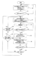
図6は、図1に示すHUD100の動作の変形例を説明するためのフローチャートである。図6に示すフローチャートは、ステップS9とステップS10が追加された点を除いては、図4と同じである。このため、図6において図4と同じ処理には同一符号を付して説明を省略する。
ステップS8の判定がYESの場合には、システム制御部60は、継続して満たされている条件の内容が、“ガソリン等の物理量の残量が閾値未満であること”であるか否かを判定する(ステップS9)。ステップS9の判定がNOの場合は、システム制御部60はステップS6に処理を戻す
ステップS9の判定がYESの場合は、システム制御部60は、“物理量の残量が閾値未満である”という条件が満たされてからの経過時間が予め決められた設定値に達したか否かを判定する(ステップS10)。この設定値は、例えば20分の倍数(20分、40分、60分、・・・)等のように複数の値が設定されてもよい。
ステップS10の判定がYESの場合には、システム制御部60はステップS2に処理を戻して、残量情報を含む画像データを駆動部45に入力する。ステップS10の判定がNOの場合には、システム制御部60はステップS6に処理を戻す。
以上の構成によれば、残量情報については、この物理量の残量が閾値未満である情報が一度表示されて運転者により認知され、非表示になったとしても、“物理量の残量が閾値未満になること”という条件が継続して満たされている間は、残量情報が例えば定期的に再表示されることになる。残量情報は、一度認知されても、時間が経過すると忘れられてしまう可能性がある。そこで、残量情報については、非表示となってから予め決められたタイミングで再表示されることによって、残量不足を運転者に対して再度周知することが可能となる。
システム制御部60は、非常在情報が認知された場合に、非常在情報をすぐに非表示にするのではなく、例えば、非常在情報の表示輝度を徐々に低下させて最終的に非表示にしたり、非常在情報の表示色を徐々に薄くして最終的に非表示にしたり、非常在情報を所定時間点滅表示させてから非表示にしたり、非常在情報を徐々に小さくしていって最終的に非表示にしたりしてもよい。また、これらの表示方法を、運転者が自由に選択可能としてもよい。このような構成により、運転者の好みにあった表示が可能となる。また、非常在情報を自然な形で消すことができる。
非常在情報としての警告情報は、運転者にとって注意を惹くものであるため、運転者がその表示に気をとられてしまい、運転に支障が出る可能性が高い。このため、HUD100により得られる効果は、非常在情報が警告情報である場合に顕著な効果をもたらすこととなる。
図7は、図1に示すHUD100の変形例であるHUD200を搭載する自動車の室内構成を示す図である。図7において、図1と同じ構成には同一符号を付して説明を省略する。
図7に示す自動車は、撮像部9が削除され、操作部10が追加された点を除いては、図1と同じ構成である。図7に示すHUD200は、システム制御部60の機能が異なる点を除いては、HUD100と同じである。
操作部10は、HUD200のシステム制御部60に情報を入力するためのタッチパネル又はボタン等により構成される。操作部10は、図7の例では、自動車のハンドル11における運転者の指が置かれる部分近傍に設けられている。
運転者は、HUD200によって表示された非常在情報を確認した場合に、操作部10を押下することによって、この非常在情報を認知したことを示す操作信号をHUD200のシステム制御部60に入力することができる。
図8は、図7に示すHUD200の制御ユニット4の詳細構成を示す模式図である。図8において図2と同じ構成には同一符号を付してある。
図8に示すHUD200のシステム制御部60は、常在情報と非常在情報を含む画像データを駆動部45に入力している状態において、操作部10から操作信号が入力されると、常在情報と非常在情報を含む画像データを、常在情報のみを含む画像データに変更し、変更後の画像データを駆動部45に入力する。
図9は、図8に示すシステム制御部60の機能ブロック図である。図9において図3と同じ構成には同一符号を付してある。
図9に示すシステム制御部60は、視線検出部61が含まれていない点を除いては、図3と同じ構成である。
図9に示すシステム制御部60の情報認知判定部64は、非常在情報を含む画像データに基づく画像が表示されている状態において、操作部10から操作信号が入力されると、運転者がこの非常在情報を認知したと判定する。
図10は、図7に示すHUD200の動作を説明するためのフローチャートである。図10において図4と同一処理には同一符号を付して説明を省略する。図10に示すフローチャートは、ステップS3が含まれず、ステップS4がステップS11に変更された点を除いては、図4に示すフローチャートと同じである。
ステップS2の後のステップS11において、システム制御部60の情報認知判定部64は、操作部10から操作信号が入力されたか否かを判定する。システム制御部60の情報認知判定部64は、操作部10から操作信号が入力されるまで待機する。
そして、システム制御部60の情報認知判定部64は、操作部10から操作信号が入力された場合(ステップS11:YES)には、運転者が非常在情報を認知したと判定する(ステップS5)。この後はステップS6以降の処理が行われる。
以上のように、図7に示すHUD200は、非常在情報が運転者により認知されたことを、運転者により操作された操作部10から入力される操作信号によって判定する。このため、非常在情報が認知されたか否かを正確に判定することができる。この構成によっても、自動車の運転に支障をきたすことなく、運転者に必要な情報を提示することができる。
また、図7に示すHUD200によれば、非常在情報を非表示にするかどうかを運転者が自らの意思で決定することができる。このため、例えば、残量情報については忘れないように表示をさせておき、ナビゲーション情報については確認した時点において非表示にする、といった柔軟な使い方が可能となる。
なお、操作部10は、ジェスチャ操作又は音声によって、システム制御部60に操作信号を入力できるものであってもよい。
HUD100に対して操作部10を更に追加し、HUD100のシステム制御部60の情報認知判定部64が、操作部10から操作信号の入力を受け入れた場合に、非常在情報が認知されたと認知してもよい。つまり、HUD100とHUD200の構成を組み合わせてもよい。
ここまでは、システム制御部60が、非常在情報が認知された場合に、この非常在情報を非表示にするものとした。この変形例として、システム制御部60は、非常在情報の表示は維持したまま、例えば、非常在情報の表示輝度を低下させたり、非常在情報の表示色を薄くしたり、非常在情報を点滅表示に変更したり、非常在情報の表示サイズを小さくしたり、非常在情報の表示位置を画面端に移動させたりしてもよい。また、これらの表示方法を、運転者が自由に選択可能としてもよい。この構成によれば、非常在情報が目立たなくなるため、非常在情報から意識をそらすことができる。また、非常在情報が消えることはないため、情報を忘れてしまう可能性を減らすことができる。
以上説明してきたように、本明細書には以下の事項が開示されている。
開示された投写型表示装置は、光源から出射される光を、入力された画像データに基づいて空間変調し、上記空間変調して得られた画像光を乗り物における投写面に投写して上記画像データに基づく画像を表示させる投写表示部と、予め決められた乗り物の作動状況及び/又は運転状況に関する条件を満たす場合に、上記条件を満たしていることを示す情報を含む画像データを上記投写表示部に入力する入力部と、上記情報を含む画像データに基づく画像が上記投写表示部によって表示された状態において、上記乗り物の運転者が上記情報を認知したか否かを判定する情報認知判定部と、を備え、上記入力部は、上記運転者によって上記情報が認知されたと判定された場合に、上記情報を除外した画像データを上記投写表示部に入力するものである。
開示された投写型表示装置は、上記運転者の視線を検出する視線検出部を更に備え、上記情報認知判定部は、上記運転者が上記情報を認知したか否かを上記視線に基づいて判定するものである。
開示された投写型表示装置は、上記情報認知判定部は、上記情報を認知したことを示す信号を入力するための操作部から上記信号の入力がなされた場合に、上記運転者が上記情報を認知したと判定するものである。
開示された投写型表示装置は、上記条件は、上記乗り物の動作に伴って減少する物理量の残量が閾値未満であることであり、上記入力部は、上記物理量の残量が閾値未満であることを示す情報を除外した画像データを上記投写表示部に入力した後の予め決められたタイミングにおいて、上記物理量の残量が閾値未満であることを示す情報を含む画像データを上記投写表示部に入力するものである。
開示された投写型表示装置は、上記情報は、運転者に警告を行うための情報を含むものである。
開示された投写型表示装置は、上記投写面は、上記乗り物のウインドシールドであるものを含む。
開示された投写型表示装置は、上記投写面は、上記乗り物に搭載されるコンバイナであるものを含む。
開示された投写表示方法は、光源から出射される光を、入力された画像データに基づいて空間変調し、上記空間変調して得られた画像光を乗り物における投写面に投写して上記画像データに基づく画像を表示させる投写表示部に対し、予め決められた乗り物の作動状況及び/又は運転状況に関する条件を満たす場合に、上記条件を満たしていることを示す情報を含む画像データを入力する入力ステップと、上記情報を含む画像データに基づく画像が上記投写表示部によって表示された状態において、上記乗り物の運転者が上記情報を認知したか否かを判定する情報認知判定ステップと、を備え、上記入力ステップでは、上記運転者によって上記情報が認知されたと判定された場合に、上記情報を除外した画像データを上記投写表示部に入力するものである。
開示された投写表示方法は、上記運転者の視線を検出する視線検出ステップを更に備え、上記情報認知判定ステップは、上記運転者が上記情報を認知したか否かを上記視線に基づいて判定するものである。
開示された投写表示方法は、上記情報認知判定ステップは、上記情報を認知したことを示す信号を入力するための操作部から上記信号の入力がなされた場合に、上記運転者が上記情報を認知したと判定するものである。
開示された投写表示方法は、上記条件は、上記乗り物の動作に伴って減少する物理量の残量が閾値未満であることであり、上記入力ステップでは、上記物理量の残量が閾値未満であることを示す情報を除外した画像データを上記投写表示部に入力した後の予め決められたタイミングにおいて、上記物理量の残量が閾値未満であることを示す情報を含む画像データを上記投写表示部に入力するものである。
開示された投写表示方法は、上記情報は、運転者に警告を行うための情報を含むものである。
開示された投写表示方法は、上記投写面は、上記乗り物のウインドシールドであるものを含む。
開示された投写表示方法は、上記投写面は、上記乗り物に搭載されるコンバイナであるものを含む。
開示された投写表示プログラムは、光源から出射される光を、入力された画像データに基づいて空間変調し、上記空間変調して得られた画像光を乗り物における投写面に投写して上記画像データに基づく画像を表示させる投写表示部に対し、予め決められた乗り物の作動状況及び/又は運転状況に関する条件を満たす場合に、上記条件を満たしていることを示す情報を含む画像データを入力する入力ステップと、上記情報を含む画像データに基づく画像が上記投写表示部によって表示された状態において、上記乗り物の運転者が上記情報を認知したか否かを判定する情報認知判定ステップと、をコンピュータに実行させるためのプログラムであって、上記入力ステップでは、上記運転者によって上記情報が認知されたと判定された場合に、上記情報を除外した画像データを上記投写表示部に入力するものである。
本発明は、特に自動車に搭載して利便性が高く、有効である。
100,200 HUD
1 ウインドシールド
2 投写面
3 ダッシュボード
4 制御ユニット
5 拡散部材
6 反射ミラー
7 凹面鏡
8 バックミラー
9 撮像部
10 操作部
11 ハンドル
40 光源ユニット
40A 光源制御部
41r R光源
41g G光源
41b B光源
42r、42g、42b コリメータレンズ
43 ダイクロイックプリズム
44 光変調素子
45 駆動部
60 システム制御部
61 視線検出部
62 画像データ生成部
63 入力部
64 情報認知判定部
2A、2B、2C 画面
101 速度情報
102 矢印アイコン
103 警告アイコン
1 ウインドシールド
2 投写面
3 ダッシュボード
4 制御ユニット
5 拡散部材
6 反射ミラー
7 凹面鏡
8 バックミラー
9 撮像部
10 操作部
11 ハンドル
40 光源ユニット
40A 光源制御部
41r R光源
41g G光源
41b B光源
42r、42g、42b コリメータレンズ
43 ダイクロイックプリズム
44 光変調素子
45 駆動部
60 システム制御部
61 視線検出部
62 画像データ生成部
63 入力部
64 情報認知判定部
2A、2B、2C 画面
101 速度情報
102 矢印アイコン
103 警告アイコン
Claims (15)
- 光源から出射される光を、入力された画像データに基づいて空間変調し、前記空間変調して得られた画像光を乗り物における投写面に投写して前記画像データに基づく画像を表示させる投写表示部と、
予め決められた乗り物の作動状況及び/又は運転状況に関する条件を満たす場合に、前記条件を満たしていることを示す情報を含む画像データを前記投写表示部に入力する入力部と、
前記情報を含む画像データに基づく画像が前記投写表示部によって表示された状態において、前記乗り物の運転者が前記情報を認知したか否かを判定する情報認知判定部と、を備え、
前記入力部は、前記運転者によって前記情報が認知されたと判定された場合に、前記情報を除外した画像データを前記投写表示部に入力する投写型表示装置。 - 請求項1記載の投写型表示装置であって、
前記運転者の視線を検出する視線検出部を更に備え、
前記情報認知判定部は、前記運転者が前記情報を認知したか否かを前記視線に基づいて判定する投写型表示装置。 - 請求項1又は2記載の投写型表示装置であって、
前記情報認知判定部は、前記情報を認知したことを示す信号を入力するための操作部から前記信号の入力がなされた場合に、前記運転者が前記情報を認知したと判定する投写型表示装置。 - 請求項1~3のいずれか1項記載の投写型表示装置であって、
前記条件は、前記乗り物の動作に伴って減少する物理量の残量が閾値未満であることであり、
前記入力部は、前記物理量の残量が閾値未満であることを示す情報を除外した画像データを前記投写表示部に入力した後の予め決められたタイミングにおいて、前記物理量の残量が閾値未満であることを示す情報を含む画像データを前記投写表示部に入力する投写型表示装置。 - 請求項1~4のいずれか1項記載の投写型表示装置であって、
前記情報は、運転者に警告を行うための情報を含む投写型表示装置。 - 請求項1~5のいずれか1項記載の投写型表示装置であって、
前記投写面は、前記乗り物のウインドシールドである投写型表示装置。 - 請求項1~5のいずれか1項記載の投写型表示装置であって、
前記投写面は、前記乗り物に搭載されるコンバイナである投写型表示装置。 - 光源から出射される光を、入力された画像データに基づいて空間変調し、前記空間変調して得られた画像光を乗り物における投写面に投写して前記画像データに基づく画像を表示させる投写表示部に対し、予め決められた乗り物の作動状況及び/又は運転状況に関する条件を満たす場合に、前記条件を満たしていることを示す情報を含む画像データを入力する入力ステップと、
前記情報を含む画像データに基づく画像が前記投写表示部によって表示された状態において、前記乗り物の運転者が前記情報を認知したか否かを判定する情報認知判定ステップと、を備え、
前記入力ステップでは、前記運転者によって前記情報が認知されたと判定された場合に、前記情報を除外した画像データを前記投写表示部に入力する投写表示方法。 - 請求項8記載の投写表示方法であって、
前記運転者の視線を検出する視線検出ステップを更に備え、
前記情報認知判定ステップは、前記運転者が前記情報を認知したか否かを前記視線に基づいて判定する投写表示方法。 - 請求項8又は9記載の投写表示方法であって、
前記情報認知判定ステップは、前記情報を認知したことを示す信号を入力するための操作部から前記信号の入力がなされた場合に、前記運転者が前記情報を認知したと判定する投写表示方法。 - 請求項8~10のいずれか1項記載の投写表示方法であって、
前記条件は、前記乗り物の動作に伴って減少する物理量の残量が閾値未満であることであり、
前記入力ステップでは、前記物理量の残量が閾値未満であることを示す情報を除外した画像データを前記投写表示部に入力した後の予め決められたタイミングにおいて、前記物理量の残量が閾値未満であることを示す情報を含む画像データを前記投写表示部に入力する投写表示方法。 - 請求項8~11のいずれか1項記載の投写表示方法であって、
前記情報は、運転者に警告を行うための情報を含む投写表示方法。 - 請求項8~12のいずれか1項記載の投写表示方法であって、
前記投写面は、前記乗り物のウインドシールドである投写表示方法。 - 請求項8~12のいずれか1項記載の投写表示方法であって、
前記投写面は、前記乗り物に搭載されるコンバイナである投写表示方法。 - 光源から出射される光を、入力された画像データに基づいて空間変調し、前記空間変調して得られた画像光を乗り物における投写面に投写して前記画像データに基づく画像を表示させる投写表示部に対し、予め決められた乗り物の作動状況及び/又は運転状況に関する条件を満たす場合に、前記条件を満たしていることを示す情報を含む画像データを入力する入力ステップと、
前記情報を含む画像データに基づく画像が前記投写表示部によって表示された状態において、前記乗り物の運転者が前記情報を認知したか否かを判定する情報認知判定ステップと、をコンピュータに実行させるためのプログラムであって、
前記入力ステップでは、前記運転者によって前記情報が認知されたと判定された場合に、前記情報を除外した画像データを前記投写表示部に入力する投写表示プログラム。
Applications Claiming Priority (2)
| Application Number | Priority Date | Filing Date | Title |
|---|---|---|---|
| JP2016030905 | 2016-02-22 | ||
| JP2016-030905 | 2016-02-22 |
Publications (1)
| Publication Number | Publication Date |
|---|---|
| WO2017145565A1 true WO2017145565A1 (ja) | 2017-08-31 |
Family
ID=59686176
Family Applications (1)
| Application Number | Title | Priority Date | Filing Date |
|---|---|---|---|
| PCT/JP2017/001145 Ceased WO2017145565A1 (ja) | 2016-02-22 | 2017-01-16 | 投写型表示装置、投写表示方法、及び、投写表示プログラム |
Country Status (1)
| Country | Link |
|---|---|
| WO (1) | WO2017145565A1 (ja) |
Cited By (2)
| Publication number | Priority date | Publication date | Assignee | Title |
|---|---|---|---|---|
| JP2020024141A (ja) * | 2018-08-07 | 2020-02-13 | 本田技研工業株式会社 | 表示装置、表示制御方法、およびプログラム |
| JP2020024578A (ja) * | 2018-08-07 | 2020-02-13 | 本田技研工業株式会社 | 表示装置、表示制御方法、およびプログラム |
Citations (5)
| Publication number | Priority date | Publication date | Assignee | Title |
|---|---|---|---|---|
| JP2005138755A (ja) * | 2003-11-07 | 2005-06-02 | Denso Corp | 虚像表示装置およびプログラム |
| JP2006017652A (ja) * | 2004-07-05 | 2006-01-19 | Mazda Motor Corp | 車両用情報表示装置 |
| JP2007087337A (ja) * | 2005-09-26 | 2007-04-05 | Toyota Motor Corp | 車輌周囲情報表示装置 |
| JP2007249567A (ja) * | 2006-03-15 | 2007-09-27 | Omron Corp | 表示装置および方法、並びにプログラム |
| JP2015041197A (ja) * | 2013-08-21 | 2015-03-02 | 三菱電機株式会社 | 表示制御装置 |
-
2017
- 2017-01-16 WO PCT/JP2017/001145 patent/WO2017145565A1/ja not_active Ceased
Patent Citations (5)
| Publication number | Priority date | Publication date | Assignee | Title |
|---|---|---|---|---|
| JP2005138755A (ja) * | 2003-11-07 | 2005-06-02 | Denso Corp | 虚像表示装置およびプログラム |
| JP2006017652A (ja) * | 2004-07-05 | 2006-01-19 | Mazda Motor Corp | 車両用情報表示装置 |
| JP2007087337A (ja) * | 2005-09-26 | 2007-04-05 | Toyota Motor Corp | 車輌周囲情報表示装置 |
| JP2007249567A (ja) * | 2006-03-15 | 2007-09-27 | Omron Corp | 表示装置および方法、並びにプログラム |
| JP2015041197A (ja) * | 2013-08-21 | 2015-03-02 | 三菱電機株式会社 | 表示制御装置 |
Cited By (6)
| Publication number | Priority date | Publication date | Assignee | Title |
|---|---|---|---|---|
| JP2020024141A (ja) * | 2018-08-07 | 2020-02-13 | 本田技研工業株式会社 | 表示装置、表示制御方法、およびプログラム |
| JP2020024578A (ja) * | 2018-08-07 | 2020-02-13 | 本田技研工業株式会社 | 表示装置、表示制御方法、およびプログラム |
| CN110816408A (zh) * | 2018-08-07 | 2020-02-21 | 本田技研工业株式会社 | 显示装置、显示控制方法及存储介质 |
| JP7121583B2 (ja) | 2018-08-07 | 2022-08-18 | 本田技研工業株式会社 | 表示装置、表示制御方法、およびプログラム |
| JP7165532B2 (ja) | 2018-08-07 | 2022-11-04 | 本田技研工業株式会社 | 表示装置、表示制御方法、およびプログラム |
| CN110816408B (zh) * | 2018-08-07 | 2023-09-15 | 本田技研工业株式会社 | 显示装置、显示控制方法及存储介质 |
Similar Documents
| Publication | Publication Date | Title |
|---|---|---|
| US10629106B2 (en) | Projection display device, projection display method, and projection display program | |
| JP6201064B2 (ja) | 投写型表示装置、安全運転支援方法、及び安全運転支援プログラム | |
| US10746988B2 (en) | Projection display device, projection control method, and non-transitory computer readable medium storing projection control program | |
| US20210003414A1 (en) | Image control apparatus, display apparatus, movable body, and image control method | |
| JP6620250B2 (ja) | 投写型表示装置、その表示制御方法及びプログラム | |
| JP6446595B2 (ja) | 投写型表示装置、投写表示方法、及び、投写表示プログラム | |
| JP2019174459A (ja) | 制御装置、表示装置、移動体、制御方法、及びプログラム | |
| JP6582143B2 (ja) | 投写型表示装置、投写型表示装置の制御方法、投写型表示装置の制御プログラム | |
| JP7508763B2 (ja) | 画像制御装置、表示装置、移動体、画像制御方法、及びプログラム | |
| JP6464326B2 (ja) | 投写型表示装置及びその制御方法 | |
| JP2020029221A (ja) | 表示装置 | |
| JPWO2020045328A1 (ja) | 表示装置 | |
| JP6515250B2 (ja) | 投写型表示装置、表示制御方法、及び表示制御プログラム | |
| WO2019189393A1 (en) | Image control apparatus, display apparatus, movable body, and image control method | |
| WO2017145565A1 (ja) | 投写型表示装置、投写表示方法、及び、投写表示プログラム | |
| JP2017149354A (ja) | ヘッドアップディスプレイ装置 |
Legal Events
| Date | Code | Title | Description |
|---|---|---|---|
| NENP | Non-entry into the national phase |
Ref country code: DE |
|
| 121 | Ep: the epo has been informed by wipo that ep was designated in this application |
Ref document number: 17756007 Country of ref document: EP Kind code of ref document: A1 |
|
| 122 | Ep: pct application non-entry in european phase |
Ref document number: 17756007 Country of ref document: EP Kind code of ref document: A1 |
|
| NENP | Non-entry into the national phase |
Ref country code: JP |