WO2017145307A1 - データ共有システム、データ共有方法及びプログラム - Google Patents
データ共有システム、データ共有方法及びプログラム Download PDFInfo
- Publication number
- WO2017145307A1 WO2017145307A1 PCT/JP2016/055511 JP2016055511W WO2017145307A1 WO 2017145307 A1 WO2017145307 A1 WO 2017145307A1 JP 2016055511 W JP2016055511 W JP 2016055511W WO 2017145307 A1 WO2017145307 A1 WO 2017145307A1
- Authority
- WO
- WIPO (PCT)
- Prior art keywords
- data
- request
- terminal
- information
- user
- Prior art date
- Legal status (The legal status is an assumption and is not a legal conclusion. Google has not performed a legal analysis and makes no representation as to the accuracy of the status listed.)
- Ceased
Links
Images






Classifications
-
- G—PHYSICS
- G06—COMPUTING OR CALCULATING; COUNTING
- G06F—ELECTRIC DIGITAL DATA PROCESSING
- G06F16/00—Information retrieval; Database structures therefor; File system structures therefor
- G06F16/20—Information retrieval; Database structures therefor; File system structures therefor of structured data, e.g. relational data
- G06F16/27—Replication, distribution or synchronisation of data between databases or within a distributed database system; Distributed database system architectures therefor
-
- G—PHYSICS
- G06—COMPUTING OR CALCULATING; COUNTING
- G06F—ELECTRIC DIGITAL DATA PROCESSING
- G06F13/00—Interconnection of, or transfer of information or other signals between, memories, input/output devices or central processing units
-
- G—PHYSICS
- G06—COMPUTING OR CALCULATING; COUNTING
- G06F—ELECTRIC DIGITAL DATA PROCESSING
- G06F21/00—Security arrangements for protecting computers, components thereof, programs or data against unauthorised activity
- G06F21/30—Authentication, i.e. establishing the identity or authorisation of security principals
- G06F21/44—Program or device authentication
-
- G—PHYSICS
- G06—COMPUTING OR CALCULATING; COUNTING
- G06F—ELECTRIC DIGITAL DATA PROCESSING
- G06F21/00—Security arrangements for protecting computers, components thereof, programs or data against unauthorised activity
- G06F21/60—Protecting data
- G06F21/62—Protecting access to data via a platform, e.g. using keys or access control rules
- G06F21/6218—Protecting access to data via a platform, e.g. using keys or access control rules to a system of files or objects, e.g. local or distributed file system or database
- G06F21/6245—Protecting personal data, e.g. for financial or medical purposes
-
- H—ELECTRICITY
- H04—ELECTRIC COMMUNICATION TECHNIQUE
- H04L—TRANSMISSION OF DIGITAL INFORMATION, e.g. TELEGRAPHIC COMMUNICATION
- H04L67/00—Network arrangements or protocols for supporting network services or applications
- H04L67/01—Protocols
- H04L67/10—Protocols in which an application is distributed across nodes in the network
-
- H—ELECTRICITY
- H04—ELECTRIC COMMUNICATION TECHNIQUE
- H04W—WIRELESS COMMUNICATION NETWORKS
- H04W12/00—Security arrangements; Authentication; Protecting privacy or anonymity
- H04W12/10—Integrity
Definitions
- the present invention relates to a data sharing system, a data sharing method, and a program for sharing data by transmitting data stored in a transmitting terminal operated by a user to a partner terminal operated by the partner user.
- data stored in the transmission side terminal can be obtained by connecting the transmission side terminal operated by the user and the counterpart side terminal operated by the counterpart user in a communicable manner. By transmitting to the side terminal, data sharing is performed between the transmission side terminal and the counterpart terminal.
- a data sharing system in which a transmitting terminal selects information that is unlikely to be held by a counterpart terminal, and can transmit the selected information to the counterpart terminal. (See Patent Document 1).
- Patent Document 1 Although it is possible to transmit information that is unlikely to be stored in the counterpart terminal, it is a case where the transmitting terminal does not want to transmit this information. There was also a risk of sending information. For this reason, information unintended by the user is also transmitted, and the convenience for the user is low.
- the present invention has been made in view of the above problems, and provides a data sharing system, a data sharing method, and a program that improve user convenience by sharing information desired by the user when sharing data. For the purpose.
- the present invention provides the following solutions.
- the invention according to the first feature is a data sharing system for sharing data by transmitting data stored in a transmitting terminal operated by a user to a counterpart terminal operated by the counterpart user, Request accepting means for accepting a request from the transmitting terminal; Request notifying means for notifying the request to the counterpart terminal; Approval means for requesting approval on the transmitting terminal whether or not to disclose information on the request to the counterpart terminal; When the approval is made, information sharing means for transmitting the information related to the request to the counterpart terminal and sharing the data; A data sharing system is provided.
- the data sharing system for sharing data by transmitting the data stored in the transmission side terminal operated by the user to the counterpart terminal operated by the counterpart user, Accepting a request from the transmitting terminal, notifying the request to the counterpart terminal, and asking the sender terminal for approval as to whether or not information about the request may be disclosed to the counterpart terminal, If approved, information about the request is transmitted to the counterpart terminal for data sharing.
- the invention according to the first feature is a category of the data sharing system, but the same actions and effects according to the category are exhibited in other categories such as a data sharing method and a program.
- the approval means can arbitrarily select information that the user discloses to the counterpart user from a plurality of information related to the request,
- the information sharing means transmits only the information selected by the approval means to the counterpart terminal for data sharing.
- a data sharing system which is an invention according to the first feature is provided.
- the user arbitrarily selects information to be disclosed to the counterpart user from among a plurality of information related to the request. It is selectable, and only the selected information is transmitted to the counterpart terminal for data sharing.
- the information sharing means arbitrarily customizes information related to the request and transmits the data to perform data sharing.
- a data sharing system which is an invention according to the first feature is provided.
- the data sharing system performs data sharing by arbitrarily customizing information on the request and transmitting the data.
- the invention according to a fourth aspect comprises storage means for storing data excluding information related to the request;
- a data sharing system that is an invention according to a first feature is provided.
- the data sharing system stores the data excluding information related to the request.
- the invention according to a fifth feature is a data sharing method for sharing data by transmitting data stored in a transmission side terminal operated by a user to a counterpart terminal operated by the counterpart user, Receiving a request from the transmitting terminal; Notifying the request to the counterpart terminal; Asking the transmitting terminal for approval as to whether or not to disclose information related to the request to the counterpart terminal; If approved, sending information about the request to the counterpart terminal for data sharing; A data sharing method is provided.
- the invention according to the sixth aspect provides a data sharing system for sharing data by transmitting data stored in a transmission side terminal operated by a user to a counterpart terminal operated by the counterpart user.
- a program characterized in that is executed is provided.
- the present invention it is possible to provide a data sharing system, a data sharing method, and a program that improve user convenience by sharing information desired by the user when sharing data.
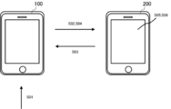
- FIG. 1 is a diagram showing an outline of the data sharing system 1.
- FIG. 2 is an overall configuration diagram of the data sharing system 1.
- FIG. 3 is a functional block diagram of the transmitting terminal 100 and the counterpart terminal 200.
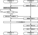
- FIG. 4 is a flowchart showing a personal data registration process executed by the transmitting terminal 100.
- FIG. 5 is a flowchart showing a request transmission process executed by the transmitting terminal 100 and the partner terminal 200.
- FIG. 6 is a flowchart showing an information disclosure process executed by the transmitting terminal 100 and the partner terminal 200.
- FIG. 7 is a diagram showing a personal data table.
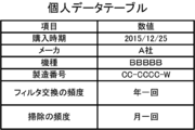
- FIG. 8 is a diagram showing a personal data table.
- FIG. 9 is a diagram showing an information disclosure content approval screen.
- FIG. 10 is a diagram showing an information disclosure content approval screen.
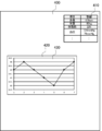
- FIG. 11 is a diagram showing shared data.
- FIG. 12 is a diagram showing shared data.
- FIG. 1 is a diagram for explaining an overview of a data sharing system 1 which is a preferred embodiment of the present invention.
- the data sharing system 1 includes a transmission side terminal 100 and a counterpart side terminal 200.
- the number of each device is not limited to one and may be plural.
- Each process described below may be configured to be executed by either or both of the above-described apparatuses.
- each device may be realized by either or both of a real device and a virtual device.
- the transmission-side terminal 100 is a terminal device operated by a user, and is a terminal device capable of data communication with the counterpart terminal 200.
- the transmitting terminal 100 is, for example, an electronic product such as a netbook terminal, a slate terminal, an electronic book terminal, and a portable music player in addition to a mobile phone, a portable information terminal, and a personal computer.
- the partner terminal 200 is a terminal device operated by the partner user, is a terminal device capable of data communication with the transmitter terminal 100, and is an electrical appliance similar to the transmitter terminal 100.
- the transmitting terminal 100 accepts an input of a request from a user (Step S01).
- the request is information for notifying the other user of the poor physical condition of the user or the malfunction of the electrical appliance owned by the user.
- the transmitting terminal 100 identifies the partner terminal 200 that is the connection destination based on the received request, and notifies the identified partner terminal 200 of the request data (step S02).
- the transmitting terminal 100 analyzes the keyword included in the request, and notifies the request data to the partner terminal 200 associated with the keyword.
- the request data includes the identifier of the transmitting terminal 100, the user's name, the content of the request, and the like.
- the counterpart terminal 200 transmits an information disclosure request as to whether or not information about the request may be disclosed to the counterpart user to the transmitter terminal 100 (step S03).
- the information related to the request is personal data such as the physical information of the own device and the information of the electrical appliance that the device 100 stores in advance.
- the transmitting-side terminal 100 Based on the received information disclosure approval request, the transmitting-side terminal 100 arbitrarily selects information to be disclosed to the counterpart user from the information on the request, and sends the disclosure status data indicating the information on the selected request to the counterpart side It transmits to the terminal 200 (step S04).
- the disclosure status data includes personal data related to the request and information indicating the disclosure status of the personal data.
- the counterpart terminal 200 receives the disclosure status data, executes data sharing with the transmission side terminal 100, displays the personal data selected by the user on its display unit based on the disclosure status data, and did not select it.
- the personal data is hidden (step S05).
- the transmission side terminal 100 also displays the data displayed by the counterpart terminal 200 as shared data.
- the partner terminal 200 may arbitrarily customize the personal data to be displayed in a graph or a table and display it on the screen. Examples of the data sharing method include screen sharing, video call using P2P, video call via a server, and video chat using a chat application.
- the data sharing method may be another method.
- the partner terminal 200 stores the shared data displayed in the shared data excluding personal data (step S06).
- FIG. 2 is a diagram showing a system configuration of the data sharing system 1 which is a preferred embodiment of the present invention.
- the data sharing system 1 includes a transmitting terminal 100, a partner terminal 200, and a public line network (Internet network, third, fourth generation communication network, etc.) 5.
- the sending terminal 100 and the partner terminal 200 may exist on the system by the number of users who execute data sharing and the number of the partner users.
- each process to be described later may be executed by either or both of the transmission-side terminal 100 and the counterpart-side terminal 200.
- the transmission-side terminal 100 and the counterpart terminal 200 may be realized by virtual devices instead of actual devices.
- a server may exist in the data sharing system 1. In this case, the server may be configured to relay data communication between the transmission-side terminal 100 and the counterpart terminal 200.
- the transmission-side terminal 100 and the partner-side terminal 200 are the above-described terminal devices having functions to be described later.
- FIG. 3 is a functional block diagram of the transmitting terminal 100 and the partner terminal 200.
- the transmitting terminal 100 includes a CPU (Central Processing Unit), a RAM (Random Access Memory), a ROM (Read Only Memory), and the like as the control unit 110, and the communication unit 120 is configured to enable communication with other devices.
- a device for example, a WiFi (Wireless Fidelity) compatible device compliant with IEEE 802.11 or a wireless device compliant with the IMT-2000 standard such as a third generation or fourth generation mobile communication system.
- the transmission-side terminal 100 includes a data storage unit such as a hard disk, a semiconductor memory, a recording medium, or a memory card as the storage unit 130.
- the transmission-side terminal 100 includes, as the input / output unit 140, a display unit that outputs and displays data and images controlled by the control unit 110, a touch panel that accepts input from the user, a keyboard, an input unit such as a mouse, and the like.
- the control unit 110 reads a predetermined program, so that the personal data acquisition module 150, the request transmission module 151, the information disclosure request reception module 152, and the disclosure status data transmission module cooperate with the communication unit 120. 153, the connection request receiving module 154 is realized.
- the personal data storage module 160 is realized in cooperation with the storage unit 130 by the control unit 110 reading a predetermined program.
- the control unit 110 reads a predetermined program, so that in cooperation with the input / output unit 140, the personal data input reception module 170, the request input reception module 171, the request analysis module 172, the information disclosure
- the content approval display module 173 is realized.
- the counterpart terminal 200 includes a CPU, RAM, ROM, and the like as the control unit 210, and includes a wireless device and the like for enabling communication with other devices as the communication unit 220.
- the unit 230 includes a data storage unit, and the input / output unit 240 includes a display unit, an input unit, and the like.
- the control unit 210 reads a predetermined program, so that the request reception module 250, the information disclosure request transmission module 251, the disclosure status data reception module 252, and the connection request transmission module cooperate with the communication unit 220. 253 is realized. Further, in the counterpart terminal 200, the control unit 210 reads a predetermined program, thereby realizing the shared data storage module 260 in cooperation with the storage unit 230. Further, in the counterpart terminal 200, the control unit 210 reads a predetermined program, thereby realizing the shared data display module 270 in cooperation with the input / output unit 240.
- FIG. 4 is a flowchart of the personal data registration process executed by the transmitting terminal 100. Processing executed by each module described above will be described together with this processing.
- the personal data input receiving module 170 determines whether or not an input of personal data from the user has been received (step S10).
- the personal data is, for example, the physical information of the user and the information on the electrical appliances held by the user. Physical information is information relating to health such as height, weight, body fat, blood pressure, blood glucose level, and immediately preceding meal content. Further, the information on the electrical appliance is information on the electrical appliance such as the purchase time, manufacturer name, model name, serial number, filter replacement frequency, and cleaning frequency.
- the personal data includes other information such as information on other individuals such as the user's assets and insurance, information on what the user holds such as vehicles and articles owned by the user, and other information. May be.
- step S10 determines in step S10 that personal data input has not been received (NO in step S10), has the personal data input receiving module 170 received input for acquiring personal data from an external device? It is determined whether or not (step S11). If the personal data input receiving module 170 determines in step S11 that input has not been received (NO in step S11), the process ends.
- the personal data acquiring module 150 acquires personal data from the external device (step S12).
- the external device transmits the personal data associated with this user based on various information such as the user's name, age, identifier of the transmitting terminal 100, serial number, MAC address, etc. transmitted by the personal data acquisition module 150.
- the personal data acquisition module 150 acquires personal data.
- the personal data storage module 160 stores the acquired personal data as a personal data table (step S13).
- the transmitting terminal 100 may be configured to transmit the acquired personal data to an external device such as a server or another computer, and the external device stores the personal data table.
- the personal data storage module 160 stores the input personal data as a personal data table (Ste S13).
- the transmitting terminal 100 may be configured to store personal data in an external device as described above.
- FIG. 7 shows a personal data table when physical information is stored as personal data.
- FIG. 8 shows a personal data table in the case of storing information on electrical appliances as personal data.
- the personal data storage module 160 stores each item in the personal data and a numerical value corresponding to each item as a personal data table.
- Each item in the personal data includes height, weight, body fat, blood pressure, blood sugar level, and the like.
- the numerical value is a value of each item.
- the personal data storage module 160 stores each item in the personal data and a numerical value corresponding to each item as a personal data table.
- Each item in the personal data includes purchase time, manufacturer name, model name, serial number, filter replacement frequency, cleaning frequency, and the like.
- the numerical value is a value, number, or character string of each item.
- the types and number of items in the personal data table may be other types and numbers than the present embodiment.
- other information for example, the date and time of input, the user's name, and the identifier may be added to the table.
- the numerical value is not limited to a number or a character string but may be a symbol or the like as a value corresponding to an item.
- FIG. 5 is a diagram illustrating a flowchart of request transmission processing executed by the transmission-side terminal 100 and the counterpart-side terminal 200. The processing executed by the modules of each device described above will be described together with this processing.
- the request input reception module 171 determines whether or not an input of a request from the user has been received (step S20).
- the request is, for example, information for notifying the other user of the malfunction of the user's body or information for notifying the other user of the malfunction of the electrical appliance owned by the user.
- the counterpart user is, for example, a doctor or manufacturing support.
- the user may say “the right side of the stomach hurts” or “the appliance does not move”.
- the request may be other than the example described above.
- the partner user may be other than the above-described example.
- step S20 when the request input receiving module 171 determines that the input of the request has not been received (step S20 NO), the process ends.
- the request analysis module 172 determines the partner terminal 200 as the connection destination based on the received request. It identifies (step S21).
- step S ⁇ b> 21 the request analysis module 172 extracts a keyword included in the received request, and specifies the counterpart terminal 200 associated with the keyword.
- the request analysis module 172 extracts, for example, “the stomach”, “the right side”, and “the pain” as keywords when the request is “the stomach right side hurts”, and the partner terminal most linked to the extracted keyword 200 is specified.
- the partner terminal 200 existing in the medical institution is specified as the connection destination.
- the request analysis module 172 extracts “electrical appliance” and “does not move” as keywords, and the counterpart terminal 200 most closely associated with the extracted keyword. Is identified.
- the partner terminal 200 existing in the manufacturing support is specified as the connection destination based on the keyword “electric appliance”.
- the request analysis module 172 may specify the partner terminal 200 based only on a specific keyword, or connect the partner terminal 200 associated with any or all of a plurality of keywords to the connection destination. May be specified. Further, the request analysis module 172 receives a method other than a keyword, for example, an input in which the request input reception module 171 specifies the counterpart terminal 200 to be a connection destination, and specifies the designated counterpart terminal 200 as a connection destination. Alternatively, it may be specified by other methods.
- the request transmission module 151 transmits request data, which is information indicating a request, to the identified counterpart terminal 200 (step S22).
- the request data includes the identifier of the transmitting terminal 100, the user's name, identification number, request content, and the like.
- the request receiving module 250 receives the request data transmitted by the transmitting terminal 100.
- the transmitting terminal 100 transmits a request to the server, the server analyzes the request, specifies the partner terminal 200 that is the connection destination, and specifies the partner terminal 200 that has been identified. Just send it.
- FIG. 6 is a diagram illustrating a flowchart of information disclosure processing executed by the transmission-side terminal 100 and the counterpart-side terminal 200. The processing executed by the modules of each device described above will be described together with this processing.
- the information disclosure request transmission module 251 transmits an information disclosure request, which is a request for approval of whether or not personal data may be disclosed to the counterpart user, to the transmission side terminal 100 (step S30).
- the disclosure request is a request for approval of whether or not personal data that is information related to the request may be disclosed to the counterpart terminal 200.
- a server may transmit an information disclosure request
- the information disclosure request receiving module 152 receives an information disclosure request.
- the information disclosure content approval display module 173 displays an information disclosure content approval screen based on the received information disclosure request (step S31).
- FIGS. 9 and 10 are diagrams illustrating an example of the information disclosure content approval screen displayed by the information disclosure content approval screen display module 173.
- FIG. 9 is a diagram showing an information disclosure content approval screen of physical information of the user as information related to the request.
- FIG. 10 is a diagram showing an information disclosure content approval screen for information on electrical appliances held by the user as information related to the request.
- the information disclosure content approval display module 173 includes, in the information disclosure content approval display area 300, a disclosure status display screen 310 in which each item of personal data, a numerical value of each item, and a disclosure status are associated with each other, and a completion icon 320. indicate. Each item and numerical value of the personal data are the same as those described above.
- the disclosure status is a column in which the user selects and specifies items to be disclosed to the counterpart terminal 200.
- the information disclosure content approval display module 173 receives a selection input from the user and designates which items are to be disclosed to the counterpart terminal 200.
- the information disclosure content approval display module 173 displays “ ⁇ ” in the disclosure status column of the item designated by the user as information disclosed to the counterpart terminal 200.
- the information disclosure content display module 173 displays “x” in the disclosure status column of items designated as information that the user does not disclose to the counterpart terminal 200 or items that have not been designated. Further, the information disclosure content approval display module 173 receives the input from the user to the completion icon 320, and determines that the designation of the personal data to be disclosed to the counterpart terminal 200 has been completed.
- the display content in the disclosure status column is not limited to the content of the present embodiment. For example, the information disclosure content display module 173 may display “YES” in the disclosure status column of information to be disclosed and “NO” in the display column of information not to be disclosed.
- a check box is displayed in the disclosure status column
- a check mark or information indicating that the information has been checked is displayed in the disclosure status column of the information to be disclosed
- a display column of information not to be disclosed is left blank. Also good.
- these display contents may be appropriately combined, or other display contents may be used.
- the information disclosure content approval display module 173 determines whether the selection is completed (step S32). In step S ⁇ b> 32, the information disclosure content approval display module 173 determines whether the selection is completed based on whether the operation of the completion icon 320 is accepted. In step S32, when the information disclosure content approval display module 173 determines that the selection is not completed (NO in step S32), that is, the information disclosure content approval display module 173 determines that the operation of the completion icon 320 is not accepted. If so, this process is repeated until an operation is accepted.
- the disclosure status data transmission module 153 displays the disclosure status data. Is transmitted to the counterpart terminal 200 (step S33).
- the disclosure status data includes information on the above-described personal data items, numerical values, and disclosure status.
- the disclosure status data receiving module 252 receives disclosure status data.
- the connection request transmission module 253 transmits a connection request for establishing a connection related to data sharing to the transmission side terminal 100 (step S34).
- the transmitting terminal 100 may transmit the disclosure status data to the server, and the server may transmit the disclosure status data to the counterpart terminal 200 or based on the disclosure status data. Thus, only personal data designated to be disclosed to the other user may be transmitted.
- the connection request receiving module 154 receives a connection request.
- the transmitting terminal 100 and the partner terminal 200 start data sharing (step S35).
- connection related to data sharing between the partner terminal 200 and the transmitter terminal 100 is not limited to the timing described above, and may be performed at another timing.
- a connection related to data sharing may be established at the timing when the transmission side terminal 100 transmits a request, or may be established at other timing.
- a connection request for establishing a connection related to data sharing may be transmitted to each of the transmitting-side terminal 100 and the counterpart terminal 200 to establish a connection related to data sharing.
- the shared data display module 270 displays the shared data (step S36).
- step S ⁇ b> 36 the transmission side terminal 100 displays the shared data as shared data in the same manner as the counterpart terminal 200.
- FIG. 11 is a diagram showing shared data in the physical information of the user displayed by the shared data display module 270.
- the shared data display module 270 displays a personal data display area 410 and a customized data display area 420 as the shared data 400.
- the transmitting terminal 100 and the partner terminal 200 mutually display data to be displayed in the shared data 400.
- personal data display area 410 personal data based on the received disclosure status data is displayed. That is, in the personal data display area 410, only the personal data approved to be disclosed to the counterpart user by the disclosure status data is displayed, and the personal data not approved to be disclosed to the counterpart user by the disclosure status data Is hidden.
- the shared data display module 270 displays height, weight, body fat, blood pressure, etc. as personal data.
- the customized data display area 420 displays customized data 430 obtained by arbitrarily customizing personal data based on the received disclosure status data.
- the customized data display area 420 displays the customized data 430 obtained by arbitrarily customizing the personal data approved to be disclosed to the other user based on the disclosure status data.
- the shared data display module 270 displays customized data 430 that shows information relating to weight as a graph.
- the shared data display module 270 acquires a plurality of pieces of information related to the weight of the same user, customizes the data on a time series based on the input information such as date and time, and displays the customized data 430 that is graphed.
- the customized data displayed in the customized data display area 420 is not limited to the present embodiment, but may be customized data obtained by customizing other items, and the display content is not limited to the graph, and may be arbitrarily set to other content. Can be customized. Further, the number of pieces of customized data displayed in the customized data display area 420 is not limited to one and may be plural or may not be displayed. Further, the content of customization is not limited to one item, but may be customized data that is customized by combining a plurality of items, and can be appropriately changed to other modes. Further, the contents of customization can be changed as appropriate based on the input from the counterpart user or the user. Further, the contents of customization may be displayed in a preset manner.
- FIG. 12 is a diagram showing shared data in the information of the electrical appliances owned by the user displayed by the shared data display module 270.
- the shared data display module 270 displays a personal data display area 410 as the shared data 400.
- the transmitting terminal 100 and the partner terminal 200 display data to be displayed on the shared data 400 with each other.
- the shared data display module 270 displays the purchase date, manufacturer, frequency of filter replacement, frequency of cleaning, and the like as items selected by the user as personal data.
- the shared data display module 270 does not display the customized data display area 420, but may display the same as in FIG.
- the shared data storage module 260 stores the displayed shared data (step S37).
- the shared data storage module 260 stores data information excluding personal data displayed in the shared data as shared data. Delete personal data without storing it.
- the counterpart terminal 200 may transmit the shared data excluding the personal data displayed in the shared data to the server, and the server may store the shared data. Further, the counterpart terminal 200 may transmit the shared data and personal data to the server, and the server may delete the personal data and store only the shared data.
- the means and functions described above are realized by a computer (including a CPU, an information processing apparatus, and various terminals) reading and executing a predetermined program.
- the program is provided in a form recorded on a computer-readable recording medium such as a flexible disk, CD (CD-ROM, etc.), DVD (DVD-ROM, DVD-RAM, etc.).
- the computer reads the program from the recording medium, transfers it to the internal storage device or the external storage device, stores it, and executes it.
- the program may be recorded in advance in a storage device (recording medium) such as a magnetic disk, an optical disk, or a magneto-optical disk, and provided from the storage device to a computer via a communication line.
Landscapes
- Engineering & Computer Science (AREA)
- Theoretical Computer Science (AREA)
- Computer Security & Cryptography (AREA)
- Physics & Mathematics (AREA)
- General Engineering & Computer Science (AREA)
- General Physics & Mathematics (AREA)
- Databases & Information Systems (AREA)
- General Health & Medical Sciences (AREA)
- Health & Medical Sciences (AREA)
- Bioethics (AREA)
- Software Systems (AREA)
- Computer Hardware Design (AREA)
- Computer Networks & Wireless Communication (AREA)
- Signal Processing (AREA)
- Medical Informatics (AREA)
- Computing Systems (AREA)
- Data Mining & Analysis (AREA)
- Information Transfer Between Computers (AREA)
- User Interface Of Digital Computer (AREA)
Abstract
Description
前記送信側端末からのリクエストを受け付けるリクエスト受付手段と、
前記リクエストを、前記相手側端末に通知するリクエスト通知手段と、
前記送信側端末に、前記リクエストに関する情報を前記相手側端末に開示してよいかどうかの承認を求める承認手段と、
前記承認なされた場合に、前記リクエストに関する情報を、前記相手側端末に送信してデータ共有を行う情報共有手段と、
を備えることを特徴とするデータ共有システムを提供する。
前記情報共有手段が、前記承認手段で選択された情報のみを、前記相手側端末に送信してデータ共有を行う、
ことを特徴とする第1の特徴に係る発明であるデータ共有システムを提供する。
ことを特徴とする第1の特徴に係る発明であるデータ共有システムを提供する。
を備えることを特徴とする第1の特徴に係る発明であるデータ共有システムを提供する。
前記送信側端末からのリクエストを受け付けるステップと、
前記リクエストを、前記相手側端末に通知するステップと、
前記送信側端末に、前記リクエストに関する情報を前記相手側端末に開示してよいかどうかの承認を求めるステップと、
前記承認なされた場合に、前記リクエストに関する情報を、前記相手側端末に送信してデータ共有を行うステップと、
を備えることを特徴とするデータ共有方法を提供する。
前記送信側端末からのリクエストを受け付けるステップ、
前記リクエストを、前記相手側端末に通知するステップ、
前記送信側端末に、前記リクエストに関する情報を前記相手側端末に開示してよいかどうかの承認を求めるステップ、
前記承認なされた場合に、前記リクエストに関する情報を、前記相手側端末に送信してデータ共有を行うステップ、
を実行させることを特徴とするプログラムを提供する。
本発明の概要について、図1に基づいて説明する。図1は、本発明の好適な実施形態であるデータ共有システム1の概要を説明するための図である。データ共有システム1は、送信側端末100及び相手側端末200から構成される。なお、各装置は1つに限らず複数であってもよい。また、後述する各処理は、上述した各装置の何れか又は双方が実行する構成であってもよい。また、各装置は、実在する装置又は仮想的な装置の何れか又は双方により実現されてもよい。
図2に基づいて、データ共有システム1のシステム構成について説明する。図2は、本発明の好適な実施形態であるデータ共有システム1のシステム構成を示す図である。データ共有システム1は、送信側端末100、相手側端末200及び公衆回線網(インターネット網や第3、第4世代通信網等)5から構成される。
図3に基づいて、送信側端末100及び相手側端末200の機能について説明する。図3は、送信側端末100及び相手側端末200の機能ブロック図を示す図である。
図4に基づいて、送信側端末100が実行する個人データ登録処理について説明する。図4は、送信側端末100が実行する個人データ登録処理のフローチャートを示す図である。上述した各モジュールが実行する処理について、本処理に併せて説明する。
図7及び図8に基づいて、個人データテーブルについて説明する。図7は、個人データとして、身体的な情報を記憶する場合における個人データテーブルを示す。また、図8は個人データとして、電化製品の情報を記憶する場合における個人データテーブルを示す。
図5に基づいて、送信側端末100及び相手側端末200が実行するリクエスト送信処理について説明する。図5は、送信側端末100及び相手側端末200が実行するリクエスト送信処理のフローチャートを示す図である。上述した各装置のモジュールが実行する処理について、本処理に併せて説明する。
次に、図6に基づいて、送信側端末100及び相手側端末200が実行する情報開示処理について説明する。図6は、送信側端末100及び相手側端末200が実行する情報開示処理のフローチャートを示す図である。上述した各装置のモジュールが実行する処理について、本処理に併せて説明する。
Claims (6)
- ユーザが操作する送信側端末に記憶されたデータを、相手側ユーザが操作する相手側端末に送信することで、データの共有を行うデータ共有システムであって、
前記送信側端末からのリクエストを受け付けるリクエスト受付手段と、
前記リクエストを、前記相手側端末に通知するリクエスト通知手段と、
前記送信側端末に、前記リクエストに関する情報を前記相手側端末に開示してよいかどうかの承認を求める承認手段と、
前記承認なされた場合に、前記リクエストに関する情報を、前記相手側端末に送信してデータ共有を行う情報共有手段と、
を備えることを特徴とするデータ共有システム。 - 前記承認手段は、前記ユーザが、前記リクエストに関する複数の情報の中から、前記相手側ユーザに開示する情報を任意に選択可能であり、
前記情報共有手段は、前記承認手段で選択された情報のみを、前記相手側端末に送信してデータ共有を行う、
ことを特徴とする請求項1に記載のデータ共有システム。 - 前記情報共有手段は、前記リクエストに関する情報を任意にカスタマイズして前記データを送信してデータ共有を行う、
ことを特徴とする請求項1に記載のデータ共有システム。 - 前記リクエストに関する情報を除いたデータを保存する保存手段と、
を備えることを特徴とする請求項1に記載のデータ共有システム。 - ユーザが操作する送信側端末に記憶されたデータを、相手側ユーザが操作する相手側端末に送信することで、データの共有を行うデータ共有方法であって、
前記送信側端末からのリクエストを受け付けるステップと、
前記リクエストを、前記相手側端末に通知するステップと、
前記送信側端末に、前記リクエストに関する情報を前記相手側端末に開示してよいかどうかの承認を求めるステップと、
前記承認なされた場合に、前記リクエストに関する情報を、前記相手側端末に送信してデータ共有を行うステップと、
を備えることを特徴とするデータ共有方法。 - ユーザが操作する送信側端末に記憶されたデータを、相手側ユーザが操作する相手側端末に送信することで、データの共有を行うデータ共有システムに、
前記送信側端末からのリクエストを受け付けるステップ、
前記リクエストを、前記相手側端末に通知するステップ、
前記送信側端末に、前記リクエストに関する情報を前記相手側端末に開示してよいかどうかの承認を求めるステップ、
前記承認なされた場合に、前記リクエストに関する情報を、前記相手側端末に送信してデータ共有を行うステップ、
を実行させることを特徴とするプログラム。
Priority Applications (3)
| Application Number | Priority Date | Filing Date | Title |
|---|---|---|---|
| PCT/JP2016/055511 WO2017145307A1 (ja) | 2016-02-24 | 2016-02-24 | データ共有システム、データ共有方法及びプログラム |
| JP2018501485A JP6441533B2 (ja) | 2016-02-24 | 2016-02-24 | データ共有システム、データ共有方法及びプログラム |
| US16/108,220 US20190012335A1 (en) | 2016-02-24 | 2018-08-22 | Data sharing system, data sharing method, and program |
Applications Claiming Priority (1)
| Application Number | Priority Date | Filing Date | Title |
|---|---|---|---|
| PCT/JP2016/055511 WO2017145307A1 (ja) | 2016-02-24 | 2016-02-24 | データ共有システム、データ共有方法及びプログラム |
Related Child Applications (1)
| Application Number | Title | Priority Date | Filing Date |
|---|---|---|---|
| US16/108,220 Continuation US20190012335A1 (en) | 2016-02-24 | 2018-08-22 | Data sharing system, data sharing method, and program |
Publications (1)
| Publication Number | Publication Date |
|---|---|
| WO2017145307A1 true WO2017145307A1 (ja) | 2017-08-31 |
Family
ID=59685986
Family Applications (1)
| Application Number | Title | Priority Date | Filing Date |
|---|---|---|---|
| PCT/JP2016/055511 Ceased WO2017145307A1 (ja) | 2016-02-24 | 2016-02-24 | データ共有システム、データ共有方法及びプログラム |
Country Status (3)
| Country | Link |
|---|---|
| US (1) | US20190012335A1 (ja) |
| JP (1) | JP6441533B2 (ja) |
| WO (1) | WO2017145307A1 (ja) |
Cited By (1)
| Publication number | Priority date | Publication date | Assignee | Title |
|---|---|---|---|---|
| JP2024108150A (ja) * | 2023-01-30 | 2024-08-09 | サービスナウ, インコーポレーテッド | データレコードの相関およびマイグレーション |
Families Citing this family (1)
| Publication number | Priority date | Publication date | Assignee | Title |
|---|---|---|---|---|
| CN110110536B (zh) * | 2019-04-30 | 2022-11-08 | 温州职业技术学院 | 一种云计算系统的数据共享方法 |
Citations (2)
| Publication number | Priority date | Publication date | Assignee | Title |
|---|---|---|---|---|
| JP2000253129A (ja) * | 1999-03-04 | 2000-09-14 | Nec Corp | 移動通信装置 |
| JP2012519997A (ja) * | 2009-03-04 | 2012-08-30 | テレフオンアクチーボラゲット エル エム エリクソン(パブル) | 通信ネットワークにおける個人情報の一時共有によって強化された通信のための方法およびノード |
Family Cites Families (7)
| Publication number | Priority date | Publication date | Assignee | Title |
|---|---|---|---|---|
| JP2003153233A (ja) * | 2001-11-12 | 2003-05-23 | Mega Chips Corp | 動画像配信システム及び動画像配信方法 |
| JP2005182280A (ja) * | 2003-12-17 | 2005-07-07 | Ibm Japan Ltd | 情報検索システム、検索結果加工システム及び情報検索方法並びにプログラム |
| JP2007005921A (ja) * | 2005-06-21 | 2007-01-11 | Matsushita Electric Ind Co Ltd | ファイルを共有する携帯端末装置とファイル共有方法 |
| US7627608B2 (en) * | 2007-02-07 | 2009-12-01 | Nokia Corporation | Sharing of media using contact data |
| US8751524B2 (en) * | 2010-10-29 | 2014-06-10 | Microsoft Corporation | Application store concierge |
| US8849819B2 (en) * | 2011-08-05 | 2014-09-30 | Deacon Johnson | System and method for controlling and organizing metadata associated with on-line content |
| US9338242B1 (en) * | 2013-09-09 | 2016-05-10 | Amazon Technologies, Inc. | Processes for generating content sharing recommendations |
-
2016
- 2016-02-24 JP JP2018501485A patent/JP6441533B2/ja active Active
- 2016-02-24 WO PCT/JP2016/055511 patent/WO2017145307A1/ja not_active Ceased
-
2018
- 2018-08-22 US US16/108,220 patent/US20190012335A1/en not_active Abandoned
Patent Citations (2)
| Publication number | Priority date | Publication date | Assignee | Title |
|---|---|---|---|---|
| JP2000253129A (ja) * | 1999-03-04 | 2000-09-14 | Nec Corp | 移動通信装置 |
| JP2012519997A (ja) * | 2009-03-04 | 2012-08-30 | テレフオンアクチーボラゲット エル エム エリクソン(パブル) | 通信ネットワークにおける個人情報の一時共有によって強化された通信のための方法およびノード |
Cited By (1)
| Publication number | Priority date | Publication date | Assignee | Title |
|---|---|---|---|---|
| JP2024108150A (ja) * | 2023-01-30 | 2024-08-09 | サービスナウ, インコーポレーテッド | データレコードの相関およびマイグレーション |
Also Published As
| Publication number | Publication date |
|---|---|
| US20190012335A1 (en) | 2019-01-10 |
| JP6441533B2 (ja) | 2018-12-19 |
| JPWO2017145307A1 (ja) | 2018-10-25 |
Similar Documents
| Publication | Publication Date | Title |
|---|---|---|
| JP5951938B2 (ja) | 端末のリモートシステム、リモート操作方法 | |
| CN108848567B (zh) | 一种内容共享的方法及装置 | |
| JP5482495B2 (ja) | 情報処理装置、情報処理方法及びプログラム | |
| US8656028B2 (en) | System, method, and program for communication connection by polling | |
| KR20070080797A (ko) | 블루투스 시스템 및 블루투스 본딩 프로세스 방법 | |
| JP2004139525A (ja) | 個人情報提供システム、個人情報提供方法 | |
| US12250186B2 (en) | Method and system for providing interoperability for rich communication suite (RCS) information sharing using plural channels | |
| CA2565757A1 (en) | System for interactively linking real entities to virtual entities thereof | |
| JP6246240B2 (ja) | 画面共有システム、画面共有方法及び、プログラム | |
| JP6441533B2 (ja) | データ共有システム、データ共有方法及びプログラム | |
| JP2007047889A (ja) | 通信制御プログラム、通信制御サーバ及び通信制御方法 | |
| JP2007104613A (ja) | 電子通信方法、電子通信システム、通信端末、およびサーバ | |
| JP5852976B2 (ja) | ユーザ端末、ユーザプロファイル表示システム、ユーザプロファイル表示方法、ユーザ端末用プログラム | |
| KR101027406B1 (ko) | 감정 인식 메시지 시스템과, 이 시스템의 모바일 통신 단말및 메시지 기억 서버 | |
| JP2010004506A (ja) | Snsシステムおよびsnsシステムのサーバ | |
| JP5632335B2 (ja) | サーバ装置及びその情報伝達方法 | |
| JP5760033B2 (ja) | ユーザ端末、ネットワークサーバ、情報共有方法、及びネットワークサーバ用プログラム | |
| JP2010257068A (ja) | 電子機器 | |
| JP6195865B2 (ja) | データ送信装置、データ送信方法及び、データ送信装置用プログラム | |
| JP4322833B2 (ja) | 無線通信システム | |
| CN102483788A (zh) | 信息处理系统、信息处理方法、信息处理设备、信息处理设备控制方法、信息处理终端、信息处理终端控制方法、信息存储介质以及程序 | |
| JP4277598B2 (ja) | 接続情報表示方法および接続情報表示プログラム。 | |
| JP6274742B2 (ja) | 電子機器設定システム、電子機器設定方法、電子機器設定システム用プログラム | |
| KR100602332B1 (ko) | 통신시스템에서의 아바타 활용 장치 및 그 방법 | |
| JP2013012164A (ja) | 管理装置、管理システム、管理方法及びプログラム |
Legal Events
| Date | Code | Title | Description |
|---|---|---|---|
| WWE | Wipo information: entry into national phase |
Ref document number: 2018501485 Country of ref document: JP |
|
| NENP | Non-entry into the national phase |
Ref country code: DE |
|
| 121 | Ep: the epo has been informed by wipo that ep was designated in this application |
Ref document number: 16891464 Country of ref document: EP Kind code of ref document: A1 |
|
| 32PN | Ep: public notification in the ep bulletin as address of the adressee cannot be established |
Free format text: NOTING OF LOSS OF RIGHTS PURSUANT TO RULE 112(1) EPC (EPO FORM 1205N DATED 31/10/2018) |
|
| 122 | Ep: pct application non-entry in european phase |
Ref document number: 16891464 Country of ref document: EP Kind code of ref document: A1 |