WO2017145224A1 - 画像受信端末、画像通信システム、画像受信方法、およびプログラム - Google Patents
画像受信端末、画像通信システム、画像受信方法、およびプログラム Download PDFInfo
- Publication number
- WO2017145224A1 WO2017145224A1 PCT/JP2016/055018 JP2016055018W WO2017145224A1 WO 2017145224 A1 WO2017145224 A1 WO 2017145224A1 JP 2016055018 W JP2016055018 W JP 2016055018W WO 2017145224 A1 WO2017145224 A1 WO 2017145224A1
- Authority
- WO
- WIPO (PCT)
- Prior art keywords
- communication
- image
- packet
- time
- processor
- Prior art date
Links
Images


Classifications
-
- H—ELECTRICITY
- H04—ELECTRIC COMMUNICATION TECHNIQUE
- H04N—PICTORIAL COMMUNICATION, e.g. TELEVISION
- H04N5/00—Details of television systems
- H04N5/04—Synchronising
- H04N5/06—Generation of synchronising signals
- H04N5/067—Arrangements or circuits at the transmitter end
-
- H—ELECTRICITY
- H04—ELECTRIC COMMUNICATION TECHNIQUE
- H04N—PICTORIAL COMMUNICATION, e.g. TELEVISION
- H04N23/00—Cameras or camera modules comprising electronic image sensors; Control thereof
- H04N23/60—Control of cameras or camera modules
-
- H—ELECTRICITY
- H04—ELECTRIC COMMUNICATION TECHNIQUE
- H04N—PICTORIAL COMMUNICATION, e.g. TELEVISION
- H04N23/00—Cameras or camera modules comprising electronic image sensors; Control thereof
- H04N23/60—Control of cameras or camera modules
- H04N23/66—Remote control of cameras or camera parts, e.g. by remote control devices
- H04N23/661—Transmitting camera control signals through networks, e.g. control via the Internet
-
- H—ELECTRICITY
- H04—ELECTRIC COMMUNICATION TECHNIQUE
- H04N—PICTORIAL COMMUNICATION, e.g. TELEVISION
- H04N7/00—Television systems
- H04N7/06—Systems for the simultaneous transmission of one television signal, i.e. both picture and sound, by more than one carrier
- H04N7/063—Simultaneous transmission of separate parts of one picture
-
- H—ELECTRICITY
- H04—ELECTRIC COMMUNICATION TECHNIQUE
- H04N—PICTORIAL COMMUNICATION, e.g. TELEVISION
- H04N7/00—Television systems
- H04N7/18—Closed-circuit television [CCTV] systems, i.e. systems in which the video signal is not broadcast
-
- H—ELECTRICITY
- H04—ELECTRIC COMMUNICATION TECHNIQUE
- H04W—WIRELESS COMMUNICATION NETWORKS
- H04W72/00—Local resource management
- H04W72/02—Selection of wireless resources by user or terminal
Definitions
- the present invention relates to an image receiving terminal, an image communication system, an image receiving method, and a program.
- the transmission side unit adds a vertical synchronization marker to image data.
- the receiving unit changes the non-display period of the image according to the marker position in the received image data. As a result, problems due to delay in receiving image data are reduced.
- Patent Document 1 cannot avoid the reception delay of image data due to the deterioration of the wireless communication environment. For this reason, omission of images in frame units cannot be reduced.
- An object of the present invention is to provide an image receiving terminal, an image communication system, an image receiving method, and a program capable of reducing an image receiving delay due to deterioration of a wireless communication environment.
- the image receiving terminal includes a communication device and one or more processors.
- An image of one frame is divided into a plurality of divided images, and the communication packet includes the divided images.
- the image of the one frame corresponds to a plurality of the communication packets.
- the processor generates a display image of one frame from the divided images included in the plurality of communication packets received by the communication device.
- the processor generates a vertical synchronization signal based on the clock.
- the processor outputs the display image to a monitor in synchronization with the vertical synchronization signal.
- the processor measures a plurality of the elapsed times by measuring an elapsed time each time the vertical synchronization signal is generated.
- the elapsed time is a time from when the vertical synchronization signal is generated to when the specific packet is received by the communication device.
- the specific packet is any one of the plurality of communication packets corresponding to the image of the one frame.
- the processor sets a determination reference time based on the plurality of measured elapsed times.
- the processor sets the communication channel used by the communication device to another communication channel based on the set determination reference time and the elapsed time measured after the determination reference time is set. Judge whether to switch to.
- the processor controls switching of the communication channel used by the communication device based on the determination result.
- the processor when the plurality of elapsed times measured after the determination reference time is set continuously exceed the determination reference time, the processor The communication channel used by the communication device may be determined to be switched to another communication channel.
- the processor may set a time based on the longest elapsed time among the plurality of measured elapsed times as the determination reference time. Good.
- the processor sets, as the determination reference time, a time based on the elapsed time having the highest appearance frequency among the measured elapsed times. May be.
- an allowable frequency may be set in advance for each of the plurality of elapsed times longer than the determination reference time.
- the allowable frequency decreases as the elapsed time becomes longer than the determination reference time.
- the elapsed time measured after the determination reference time is set exceeds the determination reference time, and the frequency of occurrence of the measured elapsed time is greater than the allowable frequency corresponding to the measured elapsed time.
- the processor may determine to switch the communication channel used by the communication device to another communication channel.
- the specific packet is any one of the communication packets other than a final packet among the plurality of communication packets corresponding to the image of the one frame. It may be one.
- the final packet is the communication packet that is received last among the plurality of communication packets corresponding to the image of the one frame.
- the processor calculates a total amount of data of the divided images that have not yet been received by the communication device among the divided images constituting the image of the one frame. May be.
- the processor may determine whether reception of the determination target packet is completed before displaying the display image by the monitor based on the total and a communication rate of the communication device.
- the determination target packet is the communication packet received by the communication device after the specific packet is received. If the reception of the determination target packet is not completed before the display of the display image by the monitor, the processor determines to switch the communication channel used by the communication device to another communication channel. May be.
- the specific packet may be a final packet.
- the final packet is the communication packet that is received last among the plurality of communication packets corresponding to the image of the one frame.
- the processor may measure a reception interval of the communication packet received before the specific packet is received.
- the processor may determine whether the remaining time in one frame when the specific packet is received is shorter than the reception interval. When the remaining time in the one frame is shorter than the reception interval of the communication packet, the processor may determine to switch the communication channel used by the communication device to another communication channel.
- the image communication system includes an image receiving terminal and an image transmitting terminal.
- the image receiving terminal includes a first communication device and one or more first processors.
- the first communication device receives a communication packet from the image transmission terminal by using a wireless communication channel.
- An image of one frame is divided into a plurality of divided images, and the communication packet includes the divided images.
- the image of the one frame corresponds to a plurality of the communication packets.
- the first processor generates a display image of one frame from the divided images included in the plurality of communication packets received by the first communication device.
- the first processor generates a vertical synchronization signal based on the clock.
- the first processor outputs the display image to a monitor in synchronization with the vertical synchronization signal.
- the first processor measures a plurality of the elapsed times by measuring an elapsed time each time the vertical synchronization signal is generated.
- the elapsed time is a time from when the vertical synchronization signal is generated to when the specific packet is received by the first communication device.
- the specific packet is any one of the plurality of communication packets corresponding to the image of the one frame.
- the first processor sets a determination reference time based on the measured elapsed times.
- the first processor uses the communication channel used by the first communication device based on the set determination reference time and the elapsed time measured after the determination reference time is set. Is determined whether to switch to another communication channel.
- the first processor controls switching of the communication channel used by the first communication device based on the determination result.
- the image transmission terminal includes an image sensor, a second processor, and a second communication device.
- the image pickup device picks up an image every imaging cycle and outputs the image of the one frame every imaging cycle.
- the second processor generates the communication packet including the divided images constituting the image of the one frame.
- the second communication device transmits the communication packet to the image receiving terminal by using the communication channel.
- the image receiving method includes a first step, a second step, a third step, a fourth step, a fifth step, and a sixth step. And a seventh step.
- the first step is a step of receiving a communication packet from an image transmission terminal by a communication device by using a wireless communication channel.
- An image of one frame is divided into a plurality of divided images, and the communication packet includes the divided images.
- the image of the one frame corresponds to a plurality of the communication packets.
- the second step is a step of generating a display image of one frame from the divided images included in the plurality of communication packets received by the communication device.
- the third step is a step of outputting the display image to a monitor in synchronization with a vertical synchronization signal.
- the vertical synchronization signal is generated based on a clock.
- the fourth step is a step of measuring a plurality of elapsed times by measuring an elapsed time each time the vertical synchronization signal is generated.
- the elapsed time is a time from when the vertical synchronization signal is generated to when the specific packet is received by the communication device.
- the specific packet is any one of the plurality of communication packets corresponding to the image of the one frame.
- the fifth step is a step of setting a determination reference time based on the plurality of measured elapsed times.
- the seventh step is a step of controlling switching of the communication channel used by the communication device based on the result of the determination.
- a program includes a first step, a second step, a third step, a fourth step, a fifth step, a sixth step,
- the computer executes the seventh step.
- the first step is a step of receiving a communication packet from an image transmission terminal by a communication device by using a wireless communication channel.
- An image of one frame is divided into a plurality of divided images, and the communication packet includes the divided images.
- the image of the one frame corresponds to a plurality of the communication packets.
- the second step is a step of generating a display image of one frame from the divided images included in the plurality of communication packets received by the communication device.
- the third step is a step of outputting the display image to a monitor in synchronization with a vertical synchronization signal.
- the vertical synchronization signal is generated based on a clock.
- the fourth step is a step of measuring a plurality of elapsed times by measuring an elapsed time each time the vertical synchronization signal is generated.
- the elapsed time is a time from when the vertical synchronization signal is generated to when the specific packet is received by the communication device.
- the specific packet is any one of the plurality of communication packets corresponding to the image of the one frame.
- the fifth step is a step of setting a determination reference time based on the plurality of measured elapsed times.
- the seventh step is a step of controlling switching of the communication channel used by the communication device based on the result of the determination.
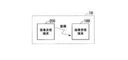
- FIG. 1 shows a configuration of an image communication system 10 according to the first embodiment of the present invention.
- the image communication system 10 includes an image reception terminal 100 and an image transmission terminal 200.
- the image receiving terminal 100 and the image transmitting terminal 200 perform wireless communication.
- the image communication system 10 is a wireless endoscope system.
- the image receiving terminal 100 is an endoscope processor, and the image transmitting terminal 200 is an endoscope scope.
- the image communication system 10 is not limited to a wireless endoscope system, and may be any system that can perform image communication wirelessly.
- the image receiving terminal 100 may be an STB (Set Top Box) that can be wirelessly connected to a digital camera or a portable terminal with a display.
- the image transmission terminal 200 may be a digital camera or a microscope.
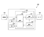
- FIG. 2 shows the configuration of the image receiving terminal 100.
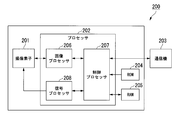
- FIG. 3 shows the configuration of the image transmission terminal 200.
- the image receiving terminal 100 includes at least a communication device 101 (first communication device) and a processor 102 (first processor).
- the communication device 101 receives a communication packet from the image transmission terminal 200 by using a wireless communication channel.
- One frame image is divided into a plurality of divided images, and the communication packet includes the divided images.
- One frame image corresponds to a plurality of communication packets.
- the processor 102 generates a display image of one frame from the divided images included in the plurality of communication packets received by the communication device 101.
- the processor 102 generates a vertical synchronization signal based on the clock.
- the processor 102 outputs the display image to the monitor 105 in synchronization with the vertical synchronization signal.
- the processor 102 measures a plurality of elapsed times by measuring the elapsed time every time the vertical synchronization signal is generated.
- the elapsed time is the time from when the vertical synchronization signal is generated to when the specific packet is received by the communication device 101.
- the specific packet is any one of a plurality of communication packets corresponding to an image of one frame.
- the processor 102 sets a determination reference time based on the plurality of measured elapsed times. Whether or not the processor 102 switches the communication channel used by the communication device 101 to another communication channel based on the set determination reference time and the elapsed time measured after the determination reference time is set Make a decision.
- the processor 102 controls switching of communication channels used by the communication device 101 based on the determination result.
- the specific packet is a communication packet that is received first among a plurality of communication packets corresponding to an image of one frame, that is, a head packet.
- the specific packet may be a communication packet other than the final packet among a plurality of communication packets corresponding to an image of one frame.
- the final packet is a communication packet received last among a plurality of communication packets corresponding to an image of one frame.
- the specific packet may be a final packet.
- the image receiving terminal 100 includes a communication device 101, a processor 102, a ROM 103, a RAM 104, and a monitor 105.
- a communication device 101 a communication device for communicating with the image receiving terminal 100.
- the communication device 101 is a wireless LAN (Local Area Network) module.
- the communication device 101 performs wireless communication with the image transmission terminal 200.
- the communication device 101 and the processor 102 are connected by a predetermined interface.
- the predetermined interface is USB (Universal Serial Bus), SDIO (Secure Digital Input / Output), or PCI Express.
- Wireless communication by the communication device 101 is performed on a communication channel set by the processor 102.
- the communication device 101 performs wireless communication using any one of a plurality of communication channels. Wireless communication by the communication device 101 is performed in accordance with protocols compliant with various interface standards.
- the communication device 101 receives a communication packet from the image transmission terminal 200 and outputs the received communication packet to the processor 102.
- the communication packet includes divided image data constituting the divided image.
- the processor 102 is composed of one or more processors.
- FIG. 2 shows an example in which the processor 102 includes a control processor 106, an image processor 107, and a signal processor 108.
- each processor includes at least one of a CPU (Central Processing Unit), an application specific integrated circuit (ASIC), an FPGA (Field-Programmable Gate Array), and the like.
- At least two of the control processor 106, the image processor 107, and the signal processor 108 may be configured as one processor.
- the control processor 106 performs various calculations and determinations according to the program.
- the program is stored in the ROM 103.
- the program in the ROM 103 is expanded in the RAM 104.
- the control processor 106 outputs the divided image data included in the plurality of communication packets received by the communication device 101 to the image processor 107.
- the control processor 106 measures the elapsed time and sets the determination reference time.
- the control processor 106 performs determination regarding communication channel switching and communication channel switching control.
- the control processor 106 controls image reception and image display of each frame based on the vertical synchronization signal.
- the control processor 106 determines to switch the communication channel used by the communication device 101 to another communication channel. In that case, the control processor 106 transmits the channel information to the image transmission terminal 200 through the communication device 101.
- the channel information indicates a communication channel used after the communication channel is switched. After the channel information is transmitted, the control processor 106 switches the communication channel used by the communication device 101 to the communication channel indicated by the channel information.
- the control processor 106 receives image data or information from the image transmission terminal 200 by the communication device 101. Specifically, the control processor 106 controls the communication device 101 so that image data or information is received from the image transmission terminal 200. That is, the control processor 106 causes the communication device 101 to receive the image data or information transmitted from the image transmission terminal 200. As a result, the communication device 101 receives image data or information from the image transmission terminal 200. The control processor 106 transmits information to the image transmission terminal 200 via the communication device 101. Specifically, the control processor 106 controls the communication device 101 so that information is transmitted to the image transmission terminal 200. That is, the control processor 106 causes the communication device 101 to transmit information for the image transmission terminal 200. As a result, the communication device 101 transmits information to the image transmission terminal 200.
- the image processor 107 generates a display image.
- the divided image data included in the communication packet received by the communication device 101 is compressed compressed image data.
- the image processor 107 generates display image data constituting a display image by expanding compressed image data corresponding to an image of one frame.
- the image processor 107 outputs the generated display image data to the monitor 105 in synchronization with the vertical synchronization signal.
- the signal processor 108 generates a vertical synchronization signal based on the clock.
- the vertical synchronization signal indicates a cycle in which the monitor 105 displays an image.
- the signal processor 108 outputs the generated vertical synchronization signal to the control processor 106 and the image processor 107.
- the signal processor 108 may be configured by a PLL (Phase Locked Loop) in the FPGA or a dedicated IC for video signal processing.
- the signal processor 108 may include an oscillating circuit such as a crystal oscillator module for generating a clock.
- control processor 106 the image processor 107, and the signal processor 108 can be realized as a software function by one processor reading and executing a program including instructions that define the operation of each processor. is there.
- This program may be provided by a “computer-readable recording medium” such as a flash memory.
- the above-described program may be transmitted to the image receiving terminal 100 from a computer having a storage device or the like in which the program is stored via a transmission medium or by a transmission wave in the transmission medium.
- a “transmission medium” for transmitting a program is a medium having a function of transmitting information, such as a network (communication network) such as the Internet or a communication line (communication line) such as a telephone line.
- the above-described program may realize a part of the functions described above.
- the above-described program may be a difference file (difference program) that can realize the above-described function in combination with a program already recorded in the computer.
- the ROM 103 is a non-volatile memory such as a Flash ROM.
- a program and various setting information are stored in the ROM 103.
- the program is used for controlling the image receiving terminal 100.
- the setting information includes communication setting parameters.
- the RAM 104 is a volatile memory.
- the RAM 104 is used as a buffer, a work area, and a temporary area.
- the buffer is used for temporary storage of image data.
- the work area is used for operations by the processor 102 and the like.
- the temporary area is used for temporary storage of various setting information.
- the monitor 105 displays the display image in units of frames according to the vertical synchronization signal.
- the monitor 105 may not be a part of the image receiving terminal 100. That is, the monitor 105 may be configured as a device independent of the image receiving terminal 100.
- the wireless communication environment has deteriorated. For this reason, an image reception delay is likely to occur. There is a high possibility that the wireless communication environment is improved by switching the communication channel. As a result of the communication channel switching, image reception delay is reduced.
- the image transmission terminal 200 includes at least an image sensor 201, a processor 202 (second processor), and a communication device 203 (second communication device).
- the image sensor 201 captures images at every imaging cycle, and outputs an image of one frame at each imaging cycle.
- the processor 202 generates a communication packet including divided images that constitute one frame image.
- the communication device 203 transmits a communication packet to the image receiving terminal 100 by using a wireless communication channel.
- the image transmission terminal 200 includes an image sensor 201, a processor 202, a communication device 203, a ROM 204, and a RAM 205.
- the image sensor 201 is an image sensor.
- the image sensor 201 is constituted by a CMOS sensor or a CCD.
- the image sensor 201 converts light imaged by the lens into an electrical signal, that is, an image signal.
- the imaging element 201 has an AD converter (analog-digital converter) that converts an analog imaging signal into a digital signal, that is, image data.
- the AD converter may be configured as a circuit subsequent to the image sensor 201.
- the image sensor 201 performs image capturing for each image capturing period in synchronization with the vertical synchronization signal, and acquires image data.
- the image sensor 201 outputs image data line by line.
- the processor 202 is composed of one or more processors.
- FIG. 3 shows an example in which the processor 202 includes an image processor 206, a control processor 207, and a signal processor 208.
- each processor includes at least one of a CPU, an application specific integrated circuit, and an FPGA.
- At least two of the image processor 206, the control processor 207, and the signal processor 208 may be configured as one processor.
- the image processor 206 processes the image output from the image sensor 201. For example, the image processor 206 generates compressed image data by compressing image data, that is, divided image data, in a predetermined line unit. Before the image data is compressed, the image processor 206 may perform image processing such as noise reduction. The compression rate of the image data may be variable. Alternatively, the image data may not be compressed.
- the control processor 207 performs various calculations and determinations according to the program.
- the program is stored in the ROM 204.
- the program in the ROM 204 is expanded in the RAM 205.
- the control processor 207 generates a communication packet including compressed divided image data, that is, compressed image data.
- One frame image corresponds to a plurality of communication packets.
- the control processor 207 outputs the generated communication packet to the communication device 203.
- the control processor 207 controls the image transmission of each frame based on the vertical synchronization signal.
- the control processor 207 controls switching of the communication channel used by the communication device 203 based on the result of switching of the communication channel by the control processor 106 of the image receiving terminal 100.
- the control processor 207 receives the channel information from the image receiving terminal 100 through the communication device 203.
- the control processor 207 switches the communication channel used by the communication device 203 to the communication channel indicated by the channel information.
- the control processor 207 transmits image data or information to the image receiving terminal 100 via the communication device 203. Specifically, the control processor 207 controls the communication device 203 so that image data or information is transmitted to the image receiving terminal 100. That is, the control processor 207 causes the communication device 203 to transmit image data or information for the image receiving terminal 100. As a result, the communication device 203 transmits image data or information to the image receiving terminal 100.
- the control processor 207 receives information from the image receiving terminal 100 via the communication device 203. Specifically, the control processor 207 controls the communication device 203 so that information is received from the image receiving terminal 100. That is, the control processor 207 causes the communication device 203 to receive information transmitted from the image receiving terminal 100. As a result, the communication device 203 receives information from the image receiving terminal 100.
- the signal processor 208 generates a vertical synchronization signal based on the clock.
- the signal processor 208 outputs the generated vertical synchronization signal to the image sensor 201 and the control processor 207.
- the signal processor 208 may be configured by a PLL in the FPGA or a dedicated IC for video signal processing.
- the signal processor 208 may include an oscillation circuit such as a crystal oscillator module for generating a clock.
- the functions of the image processor 206, the control processor 207, and the signal processor 208 can be realized as a software function by one processor reading and executing a program including instructions that define the operation of each processor. is there.
- the implementation form of this program is the same as the implementation form of the program that implements the functions of the processor 102.
- the communication device 203 is a wireless LAN module.
- the communication device 203 performs wireless communication with the image receiving terminal 100.
- the communication device 203 and the processor 202 are connected by a predetermined interface.
- Wireless communication by the communication device 203 is performed on a communication channel set by the processor 202.
- the communication device 203 performs wireless communication using any one of a plurality of communication channels. Wireless communication by the communication device 203 is performed in accordance with protocols compliant with various interface standards.
- ROM 204 is a non-volatile memory such as a Flash ROM.
- a program and various setting information are stored in the ROM 204.
- the program is used for controlling the image transmission terminal 200.
- the setting information includes communication setting parameters.
- the RAM 205 is a volatile memory.
- the RAM 205 is used as a buffer, a work area, and a temporary area.
- the buffer is used for temporary storage of image data.
- the work area is used for operations by the processor 202 and the like.
- the temporary area is used for temporary storage of various setting information.
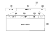
- FIG. 4 shows an example of the structure of a communication packet.
- the communication packet 300 includes a header 301, image data 302, and FCS (Frame Check Sequence) 303.
- FCS Frae Check Sequence
- the header 301 includes address information of the image receiving terminal 100 and the image transmitting terminal 200.
- the FCS 303 includes a CRC (Cyclic Redundancy Check) value for error checking.
- the image data 302 includes a frame number 304, a packet number 305, a Q value 306, an End 307, and an image data body 308.
- the frame number 304 is a number assigned to each frame image.
- the packet number 305 is a number that is incremented for each communication packet in order from 1 in an image of one frame.
- the packet number 305 starts from 1 for each frame.
- the Q value 306 is a value indicating the compression level of the image. With the Q value 306, the maximum data size of the compressed image data can be estimated. Instead of the Q value 306, data size information of a compressed one-frame image may be stored.
- End 307 indicates whether the communication packet is the last packet of an image of one frame. “1” is stored in the End 307 in the final packet of the image of one frame, and “0” is stored in the End 307 in the communication packet other than the final packet.
- the image data body 308 is compressed divided image data, that is, compressed image data.
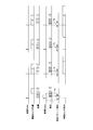
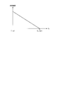
- FIG. 5 shows a schematic operation of the image receiving terminal 100 and the image transmitting terminal 200.
- the horizontal direction in FIG. 5 indicates time.
- “Transmission Vsync” indicates a vertical synchronization signal in the image transmission terminal 200.
- “Imaging and compression” indicates the timing of imaging and compression of an image in the image transmission terminal 200.
- “Transmission” indicates the timing at which the communication packet is transmitted by the image transmission terminal 200.
- “Reception Vsync” indicates a vertical synchronization signal in the image receiving terminal 100.
- “Reception” indicates the timing at which the communication packet is received by the image receiving terminal 100.
- “Specific packet detection” indicates a timing at which a specific packet is detected. In FIG. 5, the specific packet is the head packet.
- Extension and display indicates the timing of image extension and display in the image receiving terminal 100.
- the vertical sync signal indicates the start timing of the frame.
- the vertical synchronization signal in the image transmission terminal 200 is synchronized with the vertical synchronization signal in the image reception terminal 100 as a reference.
- There are various methods for synchronizing the vertical synchronization signals on the transmission side and the reception side For example, a method disclosed in Japanese Unexamined Patent Publication No. 2011-109226 may be used.
- the image sensor 201 captures an image of the subject in synchronization with the vertical synchronization signal generated by the signal processor 208 and outputs image data.
- the image processor 206 performs compression processing on the image data output from the image sensor 201.
- the control processor 207 generates a communication packet including the compressed divided image data, and outputs the generated communication packet to the communication device 203.
- the communication device 203 sequentially transmits communication packets to the image receiving terminal 100 according to the communication protocol.
- the communication device 101 sequentially receives communication packets.
- the control processor 106 detects that the head packet, which is a specific packet, has been received by the communication device 101, the control processor 106 generates a specific packet detection flag. For example, after the vertical synchronization signal is generated, the control processor 106 determines that the communication packet received first is the head packet. Alternatively, when the packet number is added to the head portion of the image data of the communication packet, the control processor 106 recognizes the communication packet having the packet number “1” as the head packet. The packet number is added to the communication packet by the control processor 207.
- the control processor 106 measures the elapsed time Ta from the time indicated by the vertical synchronization signal generated before the specific packet detection flag is generated to the time when the specific packet detection flag is generated. Immediately after image transmission is started, the determination reference time is set to an initial value. The control processor 106 updates the determination reference time based on the elapsed time Ta measured in a plurality of frames. FIG. 5 shows an operation after the determination reference time is updated.
- the control processor 106 outputs the divided image data included in the communication packet to the image processor 107.
- the image processor 107 generates display image data by expanding the divided image data corresponding to an image of one frame.
- the image processor 107 outputs the generated display image data to the monitor 105 in synchronization with the vertical synchronization signal.
- the monitor 105 displays a display image based on the display image data.
- the initial value of the determination reference time is set in consideration of the time assumed when the number of retransmissions of a specific packet is maximized and the known transmission delay time.
- the time that is assumed when the number of retransmissions of a specific packet is maximized is based on the transmission time per packet and the retransmission interval.
- the retransmission interval includes a DIFS defined in IEEE 802.11 and a backoff time.
- the transmission time per packet is calculated using an intermediate value among the values of the physical rate at which communication is possible.
- the back-off time is determined randomly within a range of a predetermined time (contention window set value CW).
- the initial value of the determination reference time may be set by the back-off time when an intermediate value of the set value CW is used.
- the known transmission delay time is a fixed value defined by the processing time of the entire system. The fixed value is stored in the ROM 103.
- the initial value of the determination reference time is set based on the time corresponding to the applied communication standard, the time corresponding to the communication speed table that can be applied on the transmission side and the reception side, and the fixed value stored in the ROM 103.
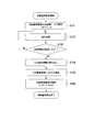
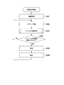
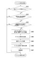
- FIG. 6 shows the overall procedure for setting the criterion.
- the control processor 106 sets the determination reference time T_ref to the initial value T_ini of the determination reference time (step S101).
- the initial value T_ini of the determination reference time is a fixed value stored in the ROM 103.
- the initial value T_ini of the determination reference time is a value calculated from the elapsed time Ta measured in the past communication. Also good.
- the initial value T_ini of the determination reference time is stored in the RAM 104.
- the image receiving terminal 100 may have an EEPROM (Electronically Erasable and Programmable Read Only Memory), and the elapsed time Ta measured during past communication may be stored in the EEPROM.
- EEPROM Electrically Erasable and Programmable Read Only Memory
- control processor 106 After the initial value T_ini of the determination reference time is set, the control processor 106 performs a measurement process.
- the control processor 106 measures the elapsed time Ta by the measurement process.
- the measurement result of the elapsed time Ta is stored in the RAM 104 as statistical information (step S102).
- control processor 106 determines whether or not a predetermined time has elapsed since the initial value T_ini of the determination reference time has been set (step S103). If the control processor 106 determines in step S103 that the predetermined time has not elapsed, the measurement process in step S102 is performed. That is, the measurement process is repeatedly performed within a predetermined time.
- step S103 when the control processor 106 determines that the predetermined time has elapsed, the control processor 106 reads the statistical information of the elapsed time Ta from the RAM 104 (step S104).
- control processor 106 extracts the longest time T_worst that is the maximum value of the elapsed time Ta from the statistical information (step S105).
- the control processor 106 updates the judgment reference time T_ref with the longest time T_worst. That is, the longest time T_worst is set as the determination reference time T_ref.
- the updated determination reference time T_ref is stored in the RAM 104 (step S106). When the determination reference time T_ref is updated, the determination reference setting is completed.
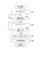
- FIG. 7 shows the procedure of the measurement process (step S102).
- the control processor 106 clears the measurement counter (step S201). At this time, the value T_cnt of the measurement counter becomes zero. The value T_cnt of the measurement counter indicates the elapsed time Ta.
- control processor 106 waits until a vertical synchronization signal is generated by the signal processor 108 (step S202).
- control processor 106 increments the value T_cnt of the measurement counter (step S203).
- control processor 106 monitors the communication device 101 and determines whether or not a specific packet has been received (step S204). If the control processor 106 determines in step S204 that the specific packet has not been received, the processing in step S204 continues.
- Step S204 when the control processor 106 determines that the specific packet is received, the control processor 106 generates a specific packet detection flag (Step S205).
- the control processor 106 updates the statistical information of the elapsed time Ta by adding the value T_cnt of the measurement counter to the statistical information of the elapsed time Ta (step S206).
- the statistical information of the elapsed time Ta is a histogram of the elapsed time Ta.
- the initial value T_ini is used as the determination reference time and the statistical information of the elapsed time Ta is accumulated in the RAM 104 until a predetermined time elapses.
- the predetermined time is a time of two frames or more. Therefore, the control processor 106 measures the elapsed time every time the vertical synchronization signal is generated in a period of two frames or more. For example, the predetermined time is 20 seconds. When one second is composed of 60 frames, the predetermined time is a time corresponding to 1200 frames. That is, the elapsed time Ta is measured 1200 times. After the predetermined time has elapsed, the control processor 106 reads a histogram of the elapsed time Ta from the RAM 104.
- the control processor 106 updates the determination reference time T_ref based on the measured value of the elapsed time Ta in the histogram.
- the determination reference time is set to the longest time T_worst which is the maximum value of the elapsed time Ta. That is, the control processor 106 sets the longest elapsed time Ta among the plurality of measured elapsed times Ta as the determination reference time T_ref.
- the judgment reference time may be set to the mode value of the elapsed time Ta. That is, the control processor 106 may set the elapsed time Ta having the highest appearance frequency among the plurality of measured elapsed times Ta as the determination reference time.
- the updated determination reference time T_ref is the maximum value of the elapsed time Ta.
- the updated determination reference time T_ref is the mode value of the measured elapsed time Ta.
- the updated determination reference time T_ref is smaller than the initial value T_ini of the determination reference time.
- the updated determination reference time T_ref may be greater than the initial value T_ini of the determination reference time.
- a stricter or looser judgment reference time may be set based on the maximum value or the mode value that is an actual measurement value of the elapsed time Ta.
- the control processor 106 may set the determination reference time T_ref in consideration of a predetermined value based on the maximum value or the mode value.
- the predetermined value may be a value considering the variation of the histogram, that is, the standard deviation ⁇ .
- the control processor 106 sets a value that is 3 ⁇ smaller than the maximum value or the mode value as the determination reference time T_ref in order to secure a margin of 3 ⁇ . As a result, a stricter judgment reference time T_ref is set.
- the control processor 106 sets the value that is 3 ⁇ larger than the maximum value or the mode value as the determination reference time T_ref. .
- a looser judgment reference time T_ref is set.
- control processor 106 sets the time based on the longest elapsed time Ta among the plurality of measured elapsed times Ta as the determination reference time T_ref.
- control processor 106 sets a time based on the elapsed time Ta having the highest appearance frequency among the plurality of measured elapsed times Ta as the determination reference time T_ref.
- the method for setting the determination reference time T_ref may be a method other than the above.
- the control processor 106 may set the determination reference time T_ref based on the statistical information of the elapsed time Ta a plurality of times. That is, the control processor 106 may constantly update the statistical information of the elapsed time Ta and periodically update the determination reference time. For example, the control processor 106 updates the determination reference time once every 60 seconds. By regularly updating the judgment reference time, a more suitable judgment reference time is set according to changes in the wireless communication environment. For this reason, the reception delay of the image accompanying the deterioration of the wireless communication environment can be reduced in real time.
- the time range in which the frequency is calculated may be set narrow. That is, the resolution in the time direction in the histogram of the elapsed time Ta may be set high. Thereby, a minute change in the elapsed time Ta can be detected.
- the operation of the image receiving terminal 100 in the reception process will be described with reference to FIG. 10 and FIG.
- the image receiving terminal 100 receives an image from the image transmitting terminal 200 by the receiving process, and displays the received image.
- the processes shown in FIGS. 10 and 11 are performed in parallel with the processes shown in FIGS.
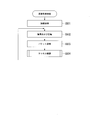
- FIG. 10 shows the overall procedure of the reception process.
- the control processor 106 performs connection processing (step S301).
- the control processor 106 connects to the image transmission terminal 200 wirelessly through the communication device 101.
- the control processor 106 sets a communication channel in the communication device 101.
- a communication link between the image receiving terminal 100 and the image transmitting terminal 200 is established, and data communication is possible. Since the connection process is a general process, a detailed description of the connection process is omitted.
- control processor 106 receives a communication packet from the image transmission terminal 200 by the communication device 101 (step S302).
- the divided image data included in the received communication packet is stored in the RAM 104.
- control processor 106 After the communication packet is received, the control processor 106 performs channel switching determination (step S303). The control processor 106 determines whether to switch the communication channel used by the communication device 101 to another communication channel based on the channel switching determination. When the wireless communication environment is deteriorated, the control processor 106 switches the communication channel.
- the control processor 106 determines whether or not an image of one frame has been received (step S304). For example, if End 307 added to the communication packet received in step S302 is “1” immediately before the determination in step S304, the control processor 106 determines that an image of one frame has been received. When End 307 is “0”, the control processor 106 determines that one frame image has not been received.
- step S304 when the control processor 106 determines that an image of one frame has not been received, the process in step S302 is performed. If the control processor 106 determines that an image of one frame has been received in step S304, the control processor 106 reads out the divided image data corresponding to the image of one frame from the RAM 104, and outputs the read divided image data to the image. Output to the processor 107.
- the image processor 107 generates display image data by expanding the divided image data corresponding to the image of one frame (step S305). As described above, the image data may not be compressed. Therefore, in step S305, the image processor 107 may generate display image data from the divided image data corresponding to the image of one frame without expanding the divided image data.
- the image processor 107 After the display image data is generated, the image processor 107 outputs the generated display image data to the monitor 105 (step S306). As a result, the monitor 105 displays a display image based on the display image data. After the display image data is output, the process in step S302 is performed.
- the control processor 106 transmits an ACK to the image transmission terminal 200 by the communication device 101.
- ACK indicates normal reception of the communication packet. Since the process regarding ACK is a general process, the process is abbreviate
- FIG. 11 shows the procedure for channel switching determination (step S303).
- the control processor 106 determines whether a specific packet has been received. That is, the control processor 106 determines whether or not the communication packet received in step S302 immediately before the channel switching determination is a specific packet (step S401). In step S401, when the control processor 106 determines that the specific packet has not been received, the channel switching determination ends.
- step S401 when the control processor 106 determines that the specific packet is received, the control processor 106 determines whether or not the measured value of the elapsed time is larger than the determination reference time (step S402). In parallel with the channel switching determination, processing similar to the measurement processing shown in FIG. 7 is performed. Thereby, the elapsed time is measured. In step S402, this elapsed time measurement is used.
- the determination reference time used in step S402 is the initial value T_ini of the determination reference time or the updated determination reference time T_ref.
- step S402 when the measured value of the elapsed time is equal to or less than the determination reference time, the control processor 106 determines not to switch the communication channel used by the communication device 101. In this case, the channel switching determination ends.
- step S402 when the measured value of the elapsed time is larger than the determination reference time, the control processor 106 determines to switch the communication channel used by the communication device 101. In this case, the control processor 106 selects the best communication channel from available communication channels other than the communication channel used by the communication device 101 (step S403).
- the communication channel selected in step S403 is different from the communication channel used by the communication device 101.
- the communication channel selected in step S403 may be a communication channel with better communication quality than the communication channel used by the communication device 101.
- the control processor 106 estimates the quality of a plurality of communication channels that can be used by the communication device 101 in parallel with the control shown in FIGS.
- a well-known method may be used as a method for estimating a communication environment state, that is, channel quality estimation. For example, while the communication channel is switched, packets are periodically transmitted from the receiving side to the transmitting side, and the error rate, RSSI (Received Signal Strength Indicator), and SN ratio (signal-to-noise ratio) A method in which any one of the above is measured can be applied.
- the communication device 101 and the communication device 203 may be configured to be able to simultaneously use a communication channel for image communication and a communication channel for channel quality estimation.
- the image receiving terminal 100 and the image transmitting terminal 200 may have a communication device for channel quality estimation in addition to the communication device 101 and the communication device 203. Since the method for switching the communication channel to a good communication channel may be a general method, a detailed description of the method is omitted.
- the control processor 106 transmits a channel switching instruction to the image transmission terminal 200 through the communication device 101 (step S404).
- the channel switching instruction includes channel information.
- the channel information indicates a communication channel used after the communication channel is switched. That is, the channel information indicates the communication channel selected in step S403.
- the control processor 106 sets the communication channel selected in step S403 in the communication device 101 (step S405). Thereby, the control processor 106 switches the communication channel set in the communication device 101 to the communication channel selected in step S403. For example, when the communication channel is switched, an initial value is set as the determination reference time.
- control processor 106 transmits a channel switching completion notification to the image transmission terminal 200 by the communication device 101 (step S406).
- the communication channel set in the communication device 101 in step S405 is used.
- the channel switching completion notification indicates completion of communication channel switching.
- the control processor 106 After the channel switching completion notification is transmitted, the control processor 106 performs connection processing (step S407). In the connection process, the control processor 106 connects to the image transmission terminal 200 wirelessly through the communication device 101. At this time, the communication channel set in the communication device 101 in step S405 is used. Through the connection process, a communication link between the image receiving terminal 100 and the image transmitting terminal 200 is established, and data communication is possible. Since the connection process is a general process, a detailed description of the connection process is omitted. When the connection process is performed, the channel switching determination ends.
- the operation of the image transmission terminal 200 in the transmission process will be described with reference to FIGS.
- the image transmission terminal 200 transmits an image to the image reception terminal 100 by transmission processing.
- FIG. 12 shows the entire procedure of the transmission process.
- the control processor 207 performs connection processing (step S501).
- the control processor 207 connects to the image receiving terminal 100 wirelessly through the communication device 203.
- the control processor 207 sets a communication channel in the communication device 203.
- the connection process in step S501 corresponds to the connection process in step S301.
- the image sensor 201 acquires image data by performing image capturing, and the image processor 206 performs compression processing on the image data (step S502).
- control processor 207 transmits a communication packet to the image receiving terminal 100 through the communication device 203 (step S503).
- the communication packet includes the divided image data compressed in step S502.
- control processor 207 After the communication packet is transmitted, the control processor 207 performs channel confirmation (step S504).
- the control processor 207 confirms whether or not switching of the communication channel is instructed from the image receiving terminal 100 by channel confirmation. When switching of the communication channel is instructed from the image receiving terminal 100, the control processor 207 switches the communication channel. After the channel confirmation is performed, the process in step S502 is performed.
- the control processor 207 receives the ACK from the image receiving terminal 100 by the communication device 203. If an ACK is received within a predetermined time, the next communication packet is transmitted. If an ACK is not received within a predetermined time, the same communication packet is retransmitted.
- the ACK processing in the MAC layer of the wireless LAN defined by IEEE 802.11 may be performed by the communication device 101 and the communication device 203. Since the process regarding ACK is a general process, the process is abbreviate
- FIG. 13 shows the procedure of channel confirmation (step S504).
- the communication device 203 receives the channel switching instruction.
- the control processor 207 monitors the communication device 203 and determines whether or not a channel switching instruction has been received (step S601). If the control processor 207 determines in step S601 that a channel switching instruction has not been received, channel confirmation ends.
- step S601 when the control processor 207 determines that the channel switching instruction is received, the control processor 207 sets the communication channel indicated by the channel information included in the channel switching instruction in the communication device 203 (step S602). As a result, the control processor 207 switches the communication channel set in the communication device 203 to the communication channel indicated by the channel information.
- the communication device 203 receives the channel switching completion notification. At this time, the communication channel set in the communication device 203 in step S602 is used. After the communication channel is switched, the control processor 207 monitors the communication device 203 and determines whether a channel switching completion notification has been received (step S603). If the control processor 207 determines in step S603 that a channel switching completion notification has not been received, the determination in step S603 continues.
- step S603 when the control processor 207 determines that a channel switching completion notification has been received, the control processor 207 performs connection processing (step S604).
- the control processor 207 connects to the image receiving terminal 100 wirelessly through the communication device 203.
- the communication channel set in the communication device 203 in step S602 is used.
- the connection process in step S604 corresponds to the connection process in step S407.
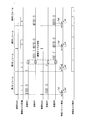
- FIGS. 14 and 15 show schematic operations of the image receiving terminal 100 and the image transmitting terminal 200 when the communication channel is switched.
- the horizontal direction in FIGS. 14 and 15 indicates time.
- the items shown in FIGS. 14 and 15 are the same as the items shown in FIG. 14 and 15, “transmission” and “reception” are shown for each of the communication channel CH1 and the communication channel CH2. 14 and 15 show the operation after the determination reference time is updated.
- the specific packet is the top packet.
- the elapsed time Ta1 to the elapsed time Ta4 measured for each of the four consecutive frames are shown.
- the communication channel CH1 is used.
- the specific packet is transmitted and received on the communication channel CH1.
- the elapsed time Ta1 is smaller than the determination reference time T_ref. For this reason, the control processor 106 determines not to switch the communication channel used by the communication device 101.
- the control processor 106 determines to switch the communication channel used by the communication device 101. In the second frame, the control processor 106 switches the communication channel used by the communication device 101 from the communication channel CH1 to the communication channel CH2. In the second frame, the communication packet after the specific packet is transmitted and received on the communication channel CH2. In the second frame, one frame of image data necessary for decompression and display is received in a time within one frame.
- the control processor 106 determines not to switch the communication channel used by the communication device 101.
- the specific packet is the final packet.
- the operation shown in FIG. 15 is the same as the operation shown in FIG. 14 except that the specific packet is the final packet.
- the communication channel CH1 is used.
- the elapsed time Ta1 is smaller than the judgment reference time T_ref
- the communication channel is not switched.
- the elapsed time Ta2 is longer than the determination reference time T_ref.
- the control processor 106 switches the communication channel used by the communication device 101 from the communication channel CH1 to the communication channel CH2.
- one frame of image data necessary for decompression and display is received in a time within one frame.
- the third and fourth frames since the elapsed time Ta3 and the elapsed time Ta4 are smaller than the judgment reference time T_ref, the communication channel is not switched.
- the specific packet may be a communication packet other than the first packet and the last packet.
- a description of the operation when the specific packet is a communication packet other than the first packet and the last packet is omitted.
- the reason why the elapsed time fluctuates is that a communication packet transmitted from the transmission side is not received at the reception side, and an ACK is not returned from the reception side to the transmission side, so that retransmission processing occurs at the transmission side.
- a possible cause of retransmission is the deterioration of the wireless communication environment.
- the deterioration of the wireless communication environment includes at least one of interference by other wireless devices, occurrence of fading, and change of the multipath environment. Therefore, there is a high possibility that the wireless communication environment is improved by changing the wireless communication channel.
- the state in which the image receiving terminal 100 and the image transmitting terminal 200 have two or more communication devices and the link of the switching destination communication channel is established may always be maintained. For example, image transmission is performed on the main channel, and a communication link is maintained on the secondary channel.
- the image receiving terminal 100 and the image transmitting terminal 200 switch the communication channel so that the image is transmitted on the sub channel. Thereby, the time required for switching the communication channel can be shortened.
- channel quality estimation may be performed every predetermined time.
- the image receiving terminal according to each aspect of the present invention may not include at least one of the ROM 103, the RAM 104, and the monitor 105.
- the image transmission terminal according to each aspect of the present invention may not include at least one of the ROM 204 and the RAM 205.
- the image receiving method of each aspect of the present invention includes a first step, a second step, a third step, a fourth step, a fifth step, a sixth step, and a seventh step. Steps.
- the processor 202 receives a communication packet from the image transmission terminal 200 by the communication device 101 by using a wireless communication channel (step S302).
- the processor 202 generates a display image of one frame from the divided images included in the plurality of communication packets received by the communication device 101 (step S305).
- the processor 202 outputs the display image to the monitor 105 in synchronization with the vertical synchronization signal (step S306).
- the processor 202 measures a plurality of elapsed times by measuring the elapsed time every time the vertical synchronization signal is generated (step S102).
- the processor 202 sets a determination reference time based on the plurality of measured elapsed times (step S106).
- the processor 202 sets the communication channel used by the communication device 101 to another communication based on the set determination reference time and the elapsed time measured after the determination reference time is set. It is determined whether or not to switch to a channel (step S402).
- the processor 202 controls switching of the communication channel used by the communication device 101 based on the determination result (step S405).
- the image receiving method of each aspect of the present invention may not include steps other than the steps corresponding to the first to seventh steps.
- whether to switch the communication channel used by the communication device 101 to another communication channel based on the determination reference time and the elapsed time measured after the determination reference time is set Judgment is made. Based on the determination result, switching of the communication channel used by the communication device 101 is controlled. For this reason, it is possible to reduce image reception delay due to deterioration of the wireless communication environment.
- the specific packet is a communication packet other than the final packet
- the deterioration of the wireless communication environment can be detected at an earlier timing within one frame of the image. For this reason, it is possible to further reduce the image reception delay accompanying the deterioration of the wireless communication environment.
- the specific packet is a communication packet other than the final packet
- the specific packet is the last packet, the image reception delay can be reduced in a frame after the frame in which the communication channel is switched.
- the processor 102 when a plurality of elapsed times measured after the determination reference time is set continuously exceed the determination reference time, the processor 102 changes the communication channel used by the communication device 101 to another To switch to the other communication channel. That is, when all of the plurality of elapsed times continuously measured exceed the determination reference time, the processor 102 determines to switch the communication channel used by the communication device 101 to another communication channel.
- the plurality of elapsed times are measured in a plurality of consecutive frames.
- the control processor 106 can determine whether or not the deterioration of the wireless communication environment continues by determining whether or not a plurality of elapsed times continuously exceed the determination reference time.
- the number of elapsed times to be determined, that is, the number of frames is two or more.
- FIG. 16 shows the procedure for channel switching determination (step S303). The operation shown in FIG. 16 will be described while referring to differences from the operation shown in FIG.
- step S402 when the measured value of the elapsed time is larger than the determination reference time, the control processor 106 determines whether or not the state where the measured value of the elapsed time is larger than the determination reference time continues. That is, the control processor 106 determines whether or not a plurality of elapsed times measured in a plurality of consecutive frames including the current frame exceed the determination reference time (step S411).
- step S411 when at least one of the plurality of elapsed times is equal to or shorter than the determination reference time, the channel switching determination ends. In step S411, when all of the plurality of elapsed times are larger than the determination reference time, the control processor 106 determines to switch the communication channel used by the communication device 101. In this case, the process in step S403 is performed.
- the state of the wireless communication environment can be determined more accurately by determining the state of a plurality of elapsed times.
- an allowable frequency is set in advance for each of a plurality of elapsed times longer than the determination reference time.
- the allowable frequency decreases as the elapsed time becomes longer than the determination reference time. If the elapsed time measured after the determination reference time is set exceeds the determination reference time and the frequency of occurrence of the measured elapsed time is greater than the allowable frequency corresponding to the measured elapsed time, the processor 102 It is determined that the communication channel used by the communication device 101 is switched to another communication channel.
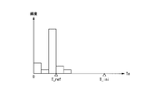
- FIG. 17 is an example of a graph showing the allowable frequency.
- the horizontal axis of the graph shown in FIG. 17 is the elapsed time Ta, and the vertical axis is the allowable frequency.
- the allowable frequency corresponding to the determination reference time T_ref is the largest.
- the allowable frequency corresponding to the limit value T_limit of the determination reference time is the smallest.
- the limit value T_limit of the determination reference time is larger than the determination reference time T_ref.
- the allowable frequency of the first elapsed time is smaller than the allowable frequency of the second elapsed time.
- the first elapsed time and the second elapsed time are included in a period from the determination reference time T_ref to the determination reference time limit value T_limit.
- the first elapsed time is longer than the second elapsed time.
- the allowable frequency is a linear function of the elapsed time Ta.
- the function indicating the relationship between the elapsed time Ta and the allowable frequency may be a function other than a linear function.
- the allowable frequency may be an exponential function of the elapsed time Ta.
- the control processor 106 calculates an allowable frequency based on the determination reference time T_ref.
- the allowable frequency information indicating the allowable frequency is stored in the RAM 104.
- the allowable frequency corresponding to the determination reference time T_ref may be a mode value in a histogram generated for updating the determination reference time.
- the limit value T_limit of the determination reference time may be the initial value T_ini of the determination reference time.
- the limit value T_limit of the determination reference time may be a time set based on a timing at which reception of one frame of image data should be completed. For example, the timing at which reception of one frame of image data is to be completed is immediately before the next vertical synchronization signal is generated at the image receiving terminal 100.
- a histogram similar to the histogram shown in FIGS. 8 and 9 is stored in the RAM 104.
- the control processor 106 updates the histogram.
- the control processor 106 extracts a frequency (occurrence frequency) corresponding to the measured elapsed time from the histogram. Further, the control processor 106 calculates an allowable frequency corresponding to the measured elapsed time based on the allowable frequency information.
- the control processor 106 compares the frequency extracted from the histogram with the allowable frequency.
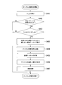
- FIG. 18 shows the procedure for channel switching determination (step S303). The operation shown in FIG. 18 will be described while referring to differences from the operation shown in FIG.
- step S402 when the measured value of the elapsed time is greater than the determination reference time, the control processor 106 determines whether or not the occurrence frequency of the elapsed time is greater than the allowable frequency (step S421).
- step S421 when the occurrence frequency of the elapsed time is equal to or less than the allowable frequency, the channel switching determination is finished.
- step S421 when the occurrence frequency of the elapsed time is greater than the allowable frequency, the control processor 106 determines to switch the communication channel used by the communication device 101. In this case, the process in step S403 is performed.
- an image reception delay can be reduced according to the degree of deterioration of the wireless communication environment.
- the specific packet is any one of communication packets other than the final packet among a plurality of communication packets corresponding to an image of one frame.
- the final packet is a communication packet received last among a plurality of communication packets corresponding to an image of one frame.
- the specific packet is a final packet.
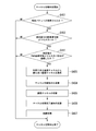
- FIG. 19 and FIG. 19 and 20 show the procedure for channel switching determination (step S303).
- the operation shown in FIGS. 19 and 20 will be described while referring to differences from the operation shown in FIG. 19 and 20, the specific packet is a communication packet other than the final packet.
- the control processor 106 calculates an average value ⁇ t_ave of the reception intervals.
- the control processor 106 acquires the total data amount d_img and the data size pkt_size (step S431).
- the average value ⁇ t_ave of the reception interval is an average value of the interval at which the communication packet of the divided image data is received.
- the communication packet of the divided image data may be a specific packet.
- the average value ⁇ t_ave of the reception interval is calculated from the reception interval of the communication packet received before the specific packet is received in the frame in which the determination regarding the switching of the communication channel is performed.
- the total data amount d_img is a data amount of image data of one frame received in a frame in which a determination regarding switching of the communication channel is performed.
- the maximum value of the size of the compressed image data based on the Q value of the communication packet may be applied as the total data amount d_img.
- the data size pkt_size is the data amount of the divided image data included in one communication packet.
- the reception interval may be used instead of the average value ⁇ t_ave of the reception interval.
- the median value ⁇ t_med in the reception interval histogram may be used.
- a value in which the standard deviation ⁇ t_ ⁇ is considered based on the average value ⁇ t_ave or the median value ⁇ t_med of the reception interval may be used.
- step S432 the control processor 106 updates the received data amount d_rcv (step S432).
- the received data amount d_rcv is the total data amount of the divided image data included in the communication packet received in the frame in which the determination regarding the switching of the communication channel is performed.
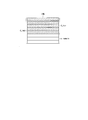
- FIG. 21 shows the total data amount d_img, the received data amount d_rcv, and the remaining data amount d_remain.
- one frame image IMG is composed of 8 lines.
- the image data of each line constitutes divided image data.
- the total data amount d_img is the total data amount of 8 lines.
- the received data amount d_rcv is the sum of the data amounts of the 5-line divided image data.
- the remaining data amount d_remain is the remaining data amount obtained by subtracting the received data amount d_rcv from the total data amount d_img. That is, the remaining data amount d_remain is the total amount of divided image data that has not yet been received by the communication device 101.
- the control processor 106 determines whether or not a specific packet has been received. That is, the control processor 106 determines whether or not the communication packet received in step S302 immediately before the channel switching determination is a specific packet (step S433). In step S433, if the control processor 106 determines that the communication packet is not a specific packet, the channel switching determination ends.
- step S433 If the control processor 106 determines in step S433 that the communication packet is a specific packet, the control processor 106 calculates the remaining data amount d_remain and acquires the communication rate Rate (step S434).
- the remaining data amount d_remain is calculated by equation (1).
- d_remain d_img ⁇ d_rcv (1)
- the communication rate Rate is a communication rate when a specific packet is received.
- the wireless LAN PHY rate may be used as the communication rate.
- the actual reception throughput may be used as the communication rate.
- the average value calculation range is one frame. That is, the average value of the reception throughput of a plurality of communication packets corresponding to one frame image is calculated.
- the calculation range of the average value may be a plurality of frames.
- the average value calculation range may be a frame included in 10 seconds. That is, when one second is composed of 60 frames, the average value calculation range may be 600 frames.
- step S435 the control processor 106 calculates an allowable time t_allow (step S435).
- the allowable time t_allow is an allowable value of the time required for receiving each communication packet received after the specific packet.
- step S435 the control processor 106 divides the remaining data amount d_remain by the data size pkt_size to calculate the number of communication packets necessary for receiving the divided image data that has not yet been received.
- step S435 the control processor 106 calculates the reception allowable time of one communication packet by dividing the remaining time t_remain by the number of communication packets. The remaining time t_remain is the remaining time in one frame.
- step S435 the control processor 106 calculates the allowable time t_allow by subtracting the average value ⁇ t_ave of the reception interval from the allowable reception time. That is, the control processor 106 calculates the allowable time t_allow according to the equation (2).
- t_allow t_remain / (d_remain / pkt_size) ⁇ t_ave (2)
- FIG. 22 shows a schematic operation of the image receiving terminal 100.
- the horizontal direction in FIG. 22 indicates time.
- “reception Vsync”, “reception”, “specific packet detection”, and “decompression and display” are shown. These items are the same as the items shown in FIG.
- the elapsed time Ta, the remaining time t_remain, and the allowable time t_allow are shown.
- the specific packet is a communication packet received fourth among a plurality of communication packets corresponding to an image of one frame.
- the remaining time t_remain is the time from when the specific packet is received to when the decompression process is started. In one frame, three communication packets are received after the specific packet.
- the allowable time t_allow is close to the time obtained by dividing the remaining time t_remain into three equal parts.
- the allowable time t_allow is based on a value obtained by equally dividing the remaining time t_remain by the number of communication packets.
- the allowable time t_allow is not limited to this.
- the remaining time t_remain may be allocated so that a longer time can be secured for a communication packet closer to the final packet.
- Equation (3) is a preset number of retransmissions.
- Expression (3) indicates that the estimated time required for reception when the communication packet including the divided image data is transmitted at the communication rate Rate is longer than the allowable time t_allow.
- the data size of the divided image data is pkt_size.
- step S436 when the expression (3) is not satisfied, the reception of the determination target packet is completed before the display image is displayed on the monitor 105. In this case, the control processor 106 determines not to switch the communication channel used by the communication device 101, and the channel switching determination ends.
- step S436 when Expression (3) is satisfied, it is estimated that the reception of the determination target packet is not completed before the display image is displayed on the monitor 105. In this case, the process in step S403 is performed.
- FIGS. 19 and 20 are the same as the operations shown in FIG.
- Multiple specific packets may exist in one frame. That is, when each of a plurality of specific packets is received in one frame, the control processor 106 determines whether reception of the determination target packet is completed before display of the display image by the monitor 105. Also good.
- the specific packet is any one of communication packets other than the final packet among a plurality of communication packets corresponding to one frame image.
- the processor 102 calculates the total amount (d_remain) of the divided images that have not yet been received by the communication device 101 among the divided images constituting one frame image (Ste S434).
- the processor 102 determines whether or not the reception of the determination target packet is completed before the display of the display image by the monitor 105, based on the total data amount (d_remain) of the divided images and the communication rate (Rate) of the communication device 101. Based on the determination (step S436).
- the determination target packet is a communication packet received by the communication device 101 after the specific packet is received. If the reception of the determination target packet is not completed before the display of the display image by the monitor 105, the processor 102 determines to switch the communication channel used by the communication device 101 to another communication channel (step S436). .
- the steps (S431, S432, S434, and S435) for obtaining information for the processor 102 to make a determination are an example.
- the processor 102 may acquire information by a method other than the above method.
- FIG. 23 shows a procedure for channel switching determination (step S303). The operation shown in FIG. 23 will be described while referring to differences from the operation shown in FIG. In the operation shown in FIG. 23, the specific packet is the final packet.
- the control processor 106 calculates the average value ⁇ t_ave of the reception intervals (step S441).
- the calculation method of the average value ⁇ t_ave of the reception intervals is the same as the method in step S431 shown in FIG. As described above, instead of the average value ⁇ t_ave of the reception intervals, other statistical values regarding the reception intervals may be used.
- the control processor 106 determines whether or not a specific packet has been received. That is, the control processor 106 determines whether or not the communication packet received in step S302 immediately before the channel switching determination is a specific packet (step S442). If the control processor 106 determines in step S442 that the communication packet is not a specific packet, the channel switching determination ends.
- step S442 when the control processor 106 determines that the communication packet is a specific packet, the control processor 106 determines whether or not the remaining time t_remain is smaller than the average value ⁇ t_ave of the reception intervals (step S443). In step S443, when the control processor 106 determines that the remaining time t_remain is smaller than the average value ⁇ t_ave of the reception intervals, the process in step S403 is performed. In step S443, when the control processor 106 determines that the remaining time t_remain is equal to or greater than the average value ⁇ t_ave of the reception intervals, the channel switching determination ends.
- the specific packet is the final packet.
- the processor 102 measures the reception interval ( ⁇ t_ave) of the communication packet received before the specific packet is received (step S441).
- the processor 102 determines whether or not the remaining time (t_remain) in one frame when the specific packet is received is shorter than the communication packet reception interval (step S443). If the remaining time in one frame is shorter than the communication packet reception interval, the processor 102 determines to switch the communication channel used by the communication device 101 to another communication channel (step S443).
- a plurality of communication packets including the final packet among a plurality of communication packets corresponding to one frame image are specific packets. If a specific packet other than the final packet is received, a determination is made in step S436. If the last packet has been received, a determination is made in step S443.
- the specific packet can be arbitrarily set in one frame.
- the wireless communication environment is determined. For this reason, it is possible to detect deterioration of the wireless communication environment at an arbitrary timing of one frame.
- the elapsed time varies depending on the position of the specific packet in the plurality of communication packets. When two or more specific packets are set in one frame, it is necessary to obtain elapsed time statistical information for each specific packet. For this reason, the processing load is high.
- the information acquired for the determination of the wireless communication environment in the fourth embodiment can be commonly used in the determination for each specific packet regardless of the position of the specific packet. For this reason, an increase in processing load is suppressed. Therefore, when two or more specific packets are set in one frame, an increase in processing load is suppressed, and real-time performance in image transmission can be further ensured.
- each embodiment of the present invention it is possible to reduce image reception delay due to deterioration of the wireless communication environment.
Abstract
画像受信端末は、通信機と、1つまたは複数のプロセッサとを有する。前記プロセッサは、複数の経過時間を測定する。前記経過時間は、垂直同期信号が生成された時点から特定パケットが前記通信機によって受信された時点までの時間である。前記プロセッサは、測定された前記複数の前記経過時間に基づいて判断基準時間を設定する。前記プロセッサは、設定された前記判断基準時間と、前記判断基準時間が設定された後に測定された前記経過時間とに基づいて、前記通信機が使用している通信チャネルを他の前記通信チャネルに切り替えるか否かの判断を行う。前記プロセッサは、前記判断の結果に基づいて、前記通信機が使用する前記通信チャネルの切替を制御する。
Description
本発明は、画像受信端末、画像通信システム、画像受信方法、およびプログラムに関する。
カメラで取得された画像データを無線で伝送するシステムがある。送信側と受信側とが非同期であることにより画像データの受信遅延が発生する場合、被写体画像の一部のデータが欠落するという不都合が生じ得る。被写体画像をリアルタイムに表示する必要がある車両後方確認装置等のカメラシステムがある。このようなカメラシステムにおいて、可能な限り遅延を低減した高信頼性の実現が望まれる。
特許文献1に開示された技術では、送信側ユニットは画像データに垂直同期マーカを付加する。受信側ユニットは、受信された画像データにおけるマーカ位置に応じて画像の非表示期間を変更する。これによって、画像データの受信遅延による不具合が低減される。
しかし、特許文献1に開示された技術では、無線通信環境の悪化に伴う画像データの受信遅延は回避できない。このため、フレーム単位の画像の欠落は低減できない。
本発明は、無線通信環境の悪化に伴う画像の受信遅延を低減することができる画像受信端末、画像通信システム、画像受信方法、およびプログラムを提供することを目的とする。
本発明の第1の態様によれば、画像受信端末は、通信機と、1つまたは複数のプロセッサとを有する。1フレームの画像は複数の分割画像に分割され、かつ前記通信パケットは前記分割画像を含む。前記1フレームの前記画像は、複数の前記通信パケットに対応する。前記プロセッサは、前記通信機によって受信された前記複数の前記通信パケットに含まれる前記分割画像から1フレームの表示画像を生成する。前記プロセッサは、クロックに基づいて垂直同期信号を生成する。前記プロセッサは、前記表示画像を前記垂直同期信号に同期してモニタに出力する。前記プロセッサは、前記垂直同期信号が生成される毎に経過時間を測定することにより複数の前記経過時間を測定する。前記経過時間は、前記垂直同期信号が生成された時点から特定パケットが前記通信機によって受信された時点までの時間である。前記特定パケットは、前記1フレームの前記画像に対応する前記複数の前記通信パケットのいずれか1つである。前記プロセッサは、測定された前記複数の前記経過時間に基づいて判断基準時間を設定する。前記プロセッサは、設定された前記判断基準時間と、前記判断基準時間が設定された後に測定された前記経過時間とに基づいて、前記通信機が使用している前記通信チャネルを他の前記通信チャネルに切り替えるか否かの判断を行う。前記プロセッサは、前記判断の結果に基づいて、前記通信機が使用する前記通信チャネルの切替を制御する。
本発明の第2の態様によれば、第1の態様において、前記判断基準時間が設定された後に測定された複数の前記経過時間が連続的に前記判断基準時間を超えた場合、前記プロセッサは、前記通信機が使用している前記通信チャネルを他の前記通信チャネルに切り替えると判断してもよい。
本発明の第3の態様によれば、第1の態様において、前記プロセッサは、測定された前記複数の前記経過時間のうち最も長い前記経過時間に基づく時間を前記判断基準時間に設定してもよい。
本発明の第4の態様によれば、第1の態様において、前記プロセッサは、測定された前記複数の前記経過時間のうち出現頻度が最も高い前記経過時間に基づく時間を前記判断基準時間に設定してもよい。
本発明の第5の態様によれば、第1の態様において、前記判断基準時間よりも長い複数の前記経過時間の各々に対して許容頻度が予め設定されてもよい。前記経過時間が前記判断基準時間よりも長くなるにつれて前記許容頻度は小さくなる。前記判断基準時間が設定された後に測定された前記経過時間が前記判断基準時間を超え、かつ測定された前記経過時間の発生頻度が、測定された前記経過時間に対応する前記許容頻度よりも大きい場合、前記プロセッサは、前記通信機が使用している前記通信チャネルを他の前記通信チャネルに切り替えると判断してもよい。
本発明の第6の態様によれば、第1の態様において、前記特定パケットは、前記1フレームの前記画像に対応する前記複数の前記通信パケットのうち最終パケット以外の前記通信パケットのいずれか1つであってもよい。前記最終パケットは、前記1フレームの画像に対応する前記複数の前記通信パケットのうち最後に受信される前記通信パケットである。前記通信機によって前記特定パケットが受信されたとき、前記プロセッサは、前記1フレームの前記画像を構成する前記分割画像のうち前記通信機によって未だ受信されていない前記分割画像のデータ量の合計を算出してもよい。前記プロセッサは、判断対象パケットの受信が、前記モニタによる前記表示画像の表示よりも前に完了するか否かを前記合計と前記通信機の通信レートとに基づいて判断してもよい。前記判断対象パケットは、前記特定パケットが受信された後に前記通信機によって受信される前記通信パケットである。前記判断対象パケットの受信が、前記モニタによる前記表示画像の表示よりも前に完了しない場合、前記プロセッサは、前記通信機が使用している前記通信チャネルを他の前記通信チャネルに切り替えると判断してもよい。
本発明の第7の態様によれば、第1の態様において、前記特定パケットは、最終パケットであってもよい。前記最終パケットは、前記1フレームの画像に対応する前記複数の前記通信パケットのうち最後に受信される前記通信パケットである。前記プロセッサは、前記特定パケットが受信される前に受信された前記通信パケットの受信間隔を測定してもよい。前記プロセッサは、前記特定パケットが受信されたときの1フレーム内の残り時間が前記受信間隔よりも短いか否かを判断してもよい。前記1フレーム内の前記残り時間が前記通信パケットの受信間隔よりも短い場合、前記プロセッサは、前記通信機が使用している前記通信チャネルを他の前記通信チャネルに切り替えると判断してもよい。
本発明の第8の態様によれば、画像通信システムは、画像受信端末と、画像送信端末とを有しする。前記画像受信端末は、第1の通信機と、1つまたは複数の第1のプロセッサとを有する。前記第1の通信機は、無線の通信チャネルを使用することにより通信パケットを前記画像送信端末から受信する。1フレームの画像は複数の分割画像に分割され、かつ前記通信パケットは前記分割画像を含む。前記1フレームの前記画像は、複数の前記通信パケットに対応する。前記第1のプロセッサは、前記第1の通信機によって受信された前記複数の前記通信パケットに含まれる前記分割画像から1フレームの表示画像を生成する。前記第1のプロセッサは、クロックに基づいて垂直同期信号を生成する。前記第1のプロセッサは、前記表示画像を前記垂直同期信号に同期してモニタに出力する。前記第1のプロセッサは、前記垂直同期信号が生成される毎に経過時間を測定することにより複数の前記経過時間を測定する。前記経過時間は、前記垂直同期信号が生成された時点から特定パケットが前記第1の通信機によって受信された時点までの時間である。前記特定パケットは、前記1フレームの前記画像に対応する前記複数の前記通信パケットのいずれか1つである。前記第1のプロセッサは、測定された前記複数の前記経過時間に基づいて判断基準時間を設定する。前記第1のプロセッサは、設定された前記判断基準時間と、前記判断基準時間が設定された後に測定された前記経過時間とに基づいて、前記第1の通信機が使用している前記通信チャネルを他の前記通信チャネルに切り替えるか否かの判断を行う。前記第1のプロセッサは、前記判断の結果に基づいて、前記第1の通信機が使用する前記通信チャネルの切替を制御する。前記画像送信端末は、撮像素子と、第2のプロセッサと、第2の通信機とを有する。前記撮像素子は、撮像周期毎に撮像を行い、かつ前記撮像周期毎に前記1フレームの前記画像を出力する。前記第2のプロセッサは、前記1フレームの前記画像を構成する前記分割画像を含む前記通信パケットを生成する。前記第2の通信機は、前記通信チャネルを使用することにより前記通信パケットを前記画像受信端末に送信する。
本発明の第9の態様によれば、画像受信方法は、第1のステップと、第2のステップと、第3のステップと、第4のステップと、第5のステップと、第6のステップと、第7のステップとを有する。前記第1のステップは、無線の通信チャネルを使用することにより通信パケットを画像送信端末から通信機によって受信するステップである。1フレームの画像は複数の分割画像に分割され、かつ前記通信パケットは前記分割画像を含む。前記1フレームの前記画像は、複数の前記通信パケットに対応する。前記第2のステップは、前記通信機によって受信された前記複数の前記通信パケットに含まれる前記分割画像から1フレームの表示画像を生成するステップである。前記第3のステップは、前記表示画像を垂直同期信号に同期してモニタに出力するステップである。前記垂直同期信号は、クロックに基づいて生成される。前記第4のステップは、前記垂直同期信号が生成される毎に経過時間を測定することにより複数の前記経過時間を測定するステップである。前記経過時間は、前記垂直同期信号が生成された時点から特定パケットが前記通信機によって受信された時点までの時間である。前記特定パケットは、前記1フレームの前記画像に対応する前記複数の前記通信パケットのいずれか1つである。前記第5のステップは、測定された前記複数の前記経過時間に基づいて判断基準時間を設定するステップである。前記第6のステップは、設定された前記判断基準時間と、前記判断基準時間が設定された後に測定された前記経過時間とに基づいて、前記通信機が使用している前記通信チャネルを他の前記通信チャネルに切り替えるか否かの判断を行うステップである。前記第7のステップは、前記判断の結果に基づいて、前記通信機が使用する前記通信チャネルの切替を制御するステップである。
本発明の第10の態様によれば、プログラムは、第1のステップと、第2のステップと、第3のステップと、第4のステップと、第5のステップと、第6のステップと、第7のステップとをコンピュータに実行させる。前記第1のステップは、無線の通信チャネルを使用することにより通信パケットを画像送信端末から通信機によって受信するステップである。1フレームの画像は複数の分割画像に分割され、かつ前記通信パケットは前記分割画像を含む。前記1フレームの前記画像は、複数の前記通信パケットに対応する。前記第2のステップは、前記通信機によって受信された前記複数の前記通信パケットに含まれる前記分割画像から1フレームの表示画像を生成するステップである。前記第3のステップは、前記表示画像を垂直同期信号に同期してモニタに出力するステップである。前記垂直同期信号は、クロックに基づいて生成される。前記第4のステップは、前記垂直同期信号が生成される毎に経過時間を測定することにより複数の前記経過時間を測定するステップである。前記経過時間は、前記垂直同期信号が生成された時点から特定パケットが前記通信機によって受信された時点までの時間である。前記特定パケットは、前記1フレームの前記画像に対応する前記複数の前記通信パケットのいずれか1つである。前記第5のステップは、測定された前記複数の前記経過時間に基づいて判断基準時間を設定するステップである。前記第6のステップは、設定された前記判断基準時間と、前記判断基準時間が設定された後に測定された前記経過時間とに基づいて、前記通信機が使用している前記通信チャネルを他の前記通信チャネルに切り替えるか否かの判断を行うステップである。前記第7のステップは、前記判断の結果に基づいて、前記通信機が使用する前記通信チャネルの切替を制御するステップである。
上記の各態様によれば、判断基準時間と、判断基準時間が設定された後に測定された経過時間とに基づいて、通信機が使用している通信チャネルを他の通信チャネルに切り替えるか否かの判断が行われる。判断の結果に基づいて、通信機が使用する通信チャネルの切替が制御される。このため、無線通信環境の悪化に伴う画像の受信遅延を低減することができる。
図面を参照し、本発明の実施形態を説明する。
(第1の実施形態)
図1は、本発明の第1の実施形態の画像通信システム10の構成を示している。図1に示すように、画像通信システム10は、画像受信端末100と画像送信端末200とを有する。画像受信端末100および画像送信端末200は無線通信を行う。例えば、画像通信システム10は、無線内視鏡システムである。例えば、画像受信端末100は内視鏡プロセッサであり、かつ画像送信端末200は内視鏡スコープである。画像通信システム10は、無線内視鏡システムに限らず、無線で画像通信を行うことができる任意のシステムであってもよい。画像受信端末100は、デジタルカメラに無線接続できるSTB(Set Top Box)またはディスプレイ付きの携帯端末であってもよい。画像送信端末200は、デジタルカメラまたは顕微鏡であってもよい。
図1は、本発明の第1の実施形態の画像通信システム10の構成を示している。図1に示すように、画像通信システム10は、画像受信端末100と画像送信端末200とを有する。画像受信端末100および画像送信端末200は無線通信を行う。例えば、画像通信システム10は、無線内視鏡システムである。例えば、画像受信端末100は内視鏡プロセッサであり、かつ画像送信端末200は内視鏡スコープである。画像通信システム10は、無線内視鏡システムに限らず、無線で画像通信を行うことができる任意のシステムであってもよい。画像受信端末100は、デジタルカメラに無線接続できるSTB(Set Top Box)またはディスプレイ付きの携帯端末であってもよい。画像送信端末200は、デジタルカメラまたは顕微鏡であってもよい。
図2は、画像受信端末100の構成を示している。図3は、画像送信端末200の構成を示している。
画像受信端末100の概略を説明する。画像受信端末100は、少なくとも通信機101(第1の通信機)と、プロセッサ102(第1のプロセッサ)とを有する。通信機101は、無線の通信チャネルを使用することにより通信パケットを画像送信端末200から受信する。1フレームの画像は複数の分割画像に分割され、かつ通信パケットは分割画像を含む。1フレームの画像は、複数の通信パケットに対応する。プロセッサ102は、通信機101によって受信された複数の通信パケットに含まれる分割画像から1フレームの表示画像を生成する。プロセッサ102は、クロックに基づいて垂直同期信号を生成する。プロセッサ102は、表示画像を垂直同期信号に同期してモニタ105に出力する。プロセッサ102は、垂直同期信号が生成される毎に経過時間を測定することにより複数の経過時間を測定する。経過時間は、垂直同期信号が生成された時点から特定パケットが通信機101によって受信された時点までの時間である。特定パケットは、1フレームの画像に対応する複数の通信パケットのいずれか1つである。プロセッサ102は、測定された複数の経過時間に基づいて判断基準時間を設定する。プロセッサ102は、設定された判断基準時間と、判断基準時間が設定された後に測定された経過時間とに基づいて、通信機101が使用している通信チャネルを他の通信チャネルに切り替えるか否かの判断を行う。プロセッサ102は、判断の結果に基づいて、通信機101が使用する通信チャネルの切替を制御する。
例えば、特定パケットは、1フレームの画像に対応する複数の通信パケットのうち最初に受信される通信パケットすなわち先頭パケットである。特定パケットが先頭パケットである場合、無線通信環境の悪化を画像の1フレーム以内の最も早いタイミングで検知することができる。特定パケットは、1フレームの画像に対応する複数の通信パケットのうち最終パケット以外の通信パケットであってもよい。最終パケットは、1フレームの画像に対応する複数の通信パケットのうち最後に受信される通信パケットである。特定パケットが最終パケット以外の通信パケットである場合、無線通信環境の悪化を画像の1フレーム以内のより早いタイミングで検知することができる。特定パケットは、最終パケットであってもよい。
画像受信端末100の詳細を説明する。図2に示すように、画像受信端末100は、通信機101と、プロセッサ102と、ROM103と、RAM104と、モニタ105とを有する。図2に示す各構成は、ハードウェアである。
例えば、通信機101は、無線LAN(Local Area Network)モジュールである。通信機101は、画像送信端末200と無線通信を行う。通信機101とプロセッサ102とは、所定のインターフェースで接続される。例えば、所定のインターフェースは、USB(Universal Serial Bus)、SDIO(Secure Digital Input/Output)、またはPCI Expressである。通信機101による無線通信は、プロセッサ102によって設定された通信チャネルで行われる。通信機101は、複数の通信チャネルのいずれか1つを使用して無線通信を行う。通信機101による無線通信は、各種インターフェースの規格に準拠したプロトコルに従って行われる。通信機101は、通信パケットを画像送信端末200から受信し、かつ受信された通信パケットをプロセッサ102に出力する。通信パケットは、分割画像を構成する分割画像データを含む。
プロセッサ102は、1つまたは複数のプロセッサで構成されている。図2において、プロセッサ102が、制御プロセッサ106と、画像プロセッサ107と、信号プロセッサ108とで構成された例が示されている。例えば、各プロセッサは、CPU(Central Processing Unit)、特定用途向け集積回路(ASIC)、およびFPGA(Field-Programmable Gate Array)等の少なくとも1つを含む。制御プロセッサ106と、画像プロセッサ107と、信号プロセッサ108との少なくとも2つが1つのプロセッサとして構成されてもよい。
制御プロセッサ106は、プログラムに従って各種の計算および判断を行う。プログラムはROM103に格納されている。画像受信端末100が起動したとき、ROM103内のプログラムはRAM104に展開される。制御プロセッサ106は、通信機101によって受信された複数の通信パケットに含まれる分割画像データを画像プロセッサ107に出力する。制御プロセッサ106は、経過時間の測定および判断基準時間の設定を行う。制御プロセッサ106は、通信チャネルの切替に関する判断および通信チャネルの切替制御を行う。制御プロセッサ106は、垂直同期信号に基づいて、各フレームの画像受信および画像表示を制御する。
判断基準時間が設定された後に測定された経過時間が判断基準時間を超えた場合、制御プロセッサ106は、通信機101が使用している通信チャネルを他の通信チャネルに切り替えると判断する。その場合、制御プロセッサ106は、チャネル情報を、通信機101によって画像送信端末200に送信する。チャネル情報は、通信チャネルが切り替えられた後に使用される通信チャネルを示す。チャネル情報が送信された後、制御プロセッサ106は、通信機101が使用している通信チャネルを、チャネル情報が示す通信チャネルに切り替える。
制御プロセッサ106は、画像データまたは情報を通信機101によって画像送信端末200から受信する。具体的には、制御プロセッサ106は、画像データまたは情報が画像送信端末200から受信されるように通信機101を制御する。つまり、制御プロセッサ106は、画像送信端末200から送信された画像データまたは情報を通信機101に受信させる。これによって、通信機101は、画像データまたは情報を画像送信端末200から受信する。制御プロセッサ106は、情報を通信機101によって画像送信端末200に送信する。具体的には、制御プロセッサ106は、情報が画像送信端末200に送信されるように通信機101を制御する。つまり、制御プロセッサ106は、画像送信端末200に対する情報を通信機101に送信させる。これによって、通信機101は、情報を画像送信端末200に送信する。
画像プロセッサ107は、表示画像を生成する。例えば、通信機101によって受信された通信パケットに含まれる分割画像データは、圧縮された圧縮画像データである。画像プロセッサ107は、1フレームの画像に対応する圧縮画像データを伸張することにより、表示画像を構成する表示画像データを生成する。画像プロセッサ107は、生成された表示画像データを垂直同期信号に同期してモニタ105に出力する。
信号プロセッサ108は、クロックに基づいて垂直同期信号を生成する。垂直同期信号は、モニタ105が画像を表示する周期を示す。信号プロセッサ108は、生成された垂直同期信号を制御プロセッサ106および画像プロセッサ107に出力する。信号プロセッサ108は、FPGA内のPLL(Phase Locked Loop)、または映像信号処理のための専用ICで構成されてもよい。信号プロセッサ108は、クロックを生成するための水晶発振器モジュールのような発振回路を有してもよい。
例えば、制御プロセッサ106と、画像プロセッサ107と、信号プロセッサ108との機能は、各プロセッサの動作を規定する命令を含むプログラムを1つのプロセッサが読み込んで実行することにより、ソフトウェアの機能として実現可能である。このプログラムは、例えばフラッシュメモリのような「コンピュータ読み取り可能な記録媒体」により提供されてもよい。また、上述したプログラムは、このプログラムが保存された記憶装置等を有するコンピュータから、伝送媒体を介して、あるいは伝送媒体中の伝送波により画像受信端末100に伝送されてもよい。プログラムを伝送する「伝送媒体」は、インターネット等のネットワーク(通信網)や電話回線等の通信回線(通信線)のように、情報を伝送する機能を有する媒体である。また、上述したプログラムは、前述した機能の一部を実現してもよい。さらに、上述したプログラムは、前述した機能をコンピュータに既に記録されているプログラムとの組合せで実現できる差分ファイル(差分プログラム)であってもよい。
ROM103は、FlashROM等の不揮発メモリである。プログラムと、各種の設定情報とがROM103に格納される。プログラムは、画像受信端末100の制御に使用される。設定情報は、通信設定パラメータを含む。RAM104は揮発メモリである。RAM104は、バッファ、ワークエリア、および一時エリアとして使用される。バッファは、画像データの一時的な格納に使用される。ワークエリアは、プロセッサ102による演算等に使用される。一時エリアは、各種の設定情報等の一時的な格納に使用される。
モニタ105は、垂直同期信号に従って表示画像を1フレーム単位で表示する。モニタ105は、画像受信端末100の一部でなくてもよい。つまり、モニタ105は、画像受信端末100から独立した装置として構成されてもよい。
測定された経過時間が判断基準時間を超えた場合、無線通信環境が悪化している。このため、画像の受信遅延が発生しやすい。通信チャネルの切替によって、無線通信環境が向上する可能性が高い。通信チャネル切替の結果、画像の受信遅延が低減する。
画像送信端末200の概略を説明する。画像送信端末200は、少なくとも撮像素子201と、プロセッサ202(第2のプロセッサ)と、通信機203(第2の通信機)とを有する。撮像素子201は、撮像周期毎に撮像を行い、かつ撮像周期毎に1フレームの画像を出力する。プロセッサ202は、1フレームの画像を構成する分割画像を含む通信パケットを生成する。通信機203は、無線の通信チャネルを使用することにより通信パケットを画像受信端末100に送信する。
画像送信端末200の詳細を説明する。図3に示すように、画像送信端末200は、撮像素子201と、プロセッサ202と、通信機203と、ROM204と、RAM205とを有する。
撮像素子201は、イメージセンサである。例えば、撮像素子201は、CMOSセンサまたはCCDで構成されている。撮像素子201は、レンズによって結像された光を電気信号すなわち撮像信号に変換する。撮像素子201は、アナログ撮像信号をデジタル信号すなわち画像データに変換するAD変換器(アナログ-デジタル変換器)を有する。AD変換器は、撮像素子201の後段の回路として構成されてもよい。撮像素子201は、垂直同期信号に同期して撮像周期毎に撮像を行い、かつ画像データを取得する。撮像素子201は、ライン単位で画像データを出力する。
プロセッサ202は、1つまたは複数のプロセッサで構成されている。図3において、プロセッサ202が、画像プロセッサ206と、制御プロセッサ207と、信号プロセッサ208とで構成された例が示されている。例えば、各プロセッサは、CPU、特定用途向け集積回路、およびFPGA等の少なくとも1つを含む。画像プロセッサ206と、制御プロセッサ207と、信号プロセッサ208との少なくとも2つが1つのプロセッサとして構成されてもよい。
画像プロセッサ206は、撮像素子201から出力された画像を処理する。例えば、画像プロセッサ206は、所定のライン単位で画像データすなわち分割画像データを圧縮することにより、圧縮画像データを生成する。画像データが圧縮される前に画像プロセッサ206は、ノイズリダクション等の画像処理を行ってもよい。画像データの圧縮率は可変でもよい。あるいは、画像データは圧縮されなくてもよい。
制御プロセッサ207は、プログラムに従って各種の計算および判断を行う。プログラムはROM204に格納されている。画像送信端末200が起動したとき、ROM204内のプログラムはRAM205に展開される。制御プロセッサ207は、圧縮された分割画像データすなわち圧縮画像データを含む通信パケットを生成する。1フレームの画像は複数の通信パケットに対応する。制御プロセッサ207は、生成された通信パケットを通信機203に出力する。制御プロセッサ207は、垂直同期信号に基づいて、各フレームの画像送信を制御する。
制御プロセッサ207は、画像受信端末100の制御プロセッサ106による通信チャネルの切替の結果に基づいて、通信機203が使用する通信チャネルの切替を制御する。チャネル情報が画像受信端末100から送信された場合、制御プロセッサ207は、チャネル情報を通信機203によって画像受信端末100から受信する。制御プロセッサ207は、通信機203が使用する通信チャネルを、チャネル情報が示す通信チャネルに切り替える。
制御プロセッサ207は、画像データまたは情報を通信機203によって画像受信端末100に送信する。具体的には、制御プロセッサ207は、画像データまたは情報が画像受信端末100に送信されるように通信機203を制御する。つまり、制御プロセッサ207は、画像受信端末100に対する画像データまたは情報を通信機203に送信させる。これによって、通信機203は、画像データまたは情報を画像受信端末100に送信する。制御プロセッサ207は、情報を通信機203によって画像受信端末100から受信する。具体的には、制御プロセッサ207は、情報が画像受信端末100から受信されるように通信機203を制御する。つまり、制御プロセッサ207は、画像受信端末100から送信された情報を通信機203に受信させる。これによって、通信機203は、情報を画像受信端末100から受信する。
信号プロセッサ208は、クロックに基づいて垂直同期信号を生成する。信号プロセッサ208は、生成された垂直同期信号を撮像素子201および制御プロセッサ207に出力する。信号プロセッサ208は、FPGA内のPLL、または映像信号処理のための専用ICで構成されてもよい。信号プロセッサ208は、クロックを生成するための水晶発振器モジュールのような発振回路を有してもよい。
例えば、画像プロセッサ206と、制御プロセッサ207と、信号プロセッサ208との機能は、各プロセッサの動作を規定する命令を含むプログラムを1つのプロセッサが読み込んで実行することにより、ソフトウェアの機能として実現可能である。このプログラムの実現形態は、プロセッサ102の機能を実現するプログラムの実現形態と同様である。
例えば、通信機203は、無線LANモジュールである。通信機203は、画像受信端末100と無線通信を行う。通信機203とプロセッサ202とは、所定のインターフェースで接続される。通信機203による無線通信は、プロセッサ202によって設定された通信チャネルで行われる。通信機203は、複数の通信チャネルのいずれか1つを使用して無線通信を行う。通信機203による無線通信は、各種インターフェースの規格に準拠したプロトコルに従って行われる。
ROM204は、FlashROM等の不揮発メモリである。プログラムと、各種の設定情報とがROM204に格納される。プログラムは、画像送信端末200の制御に使用される。設定情報は、通信設定パラメータを含む。RAM205は揮発メモリである。RAM205は、バッファ、ワークエリア、および一時エリアとして使用される。バッファは、画像データの一時的な格納に使用される。ワークエリアは、プロセッサ202による演算等に使用される。一時エリアは、各種の設定情報等の一時的な格納に使用される。
図4は、通信パケットの構成の例を示している。通信パケット300は、ヘッダ301と、画像データ302と、FCS(Frame Check Sequence)303とを含む。
ヘッダ301は、画像受信端末100および画像送信端末200のアドレス情報を含む。FCS303は、エラーチェックのためのCRC(Cyclic Redundancy Check)値を含む。
画像データ302は、フレーム番号304と、パケット番号305と、Q値306と、End307と、画像データ本体308とを含む。フレーム番号304は、1フレームの画像毎に付与される番号である。パケット番号305は、1フレームの画像の中で1から順番に通信パケット毎にインクリメントされる番号である。パケット番号305は、フレーム毎に1から開始される。Q値306は、画像の圧縮レベルを示す値である。Q値306によって、圧縮された画像データの最大データサイズが推定可能である。Q値306の代わりに、圧縮された1フレームの画像のデータサイズ情報が格納されてもよい。End307は、通信パケットが1フレームの画像の最終パケットであるか否かを示す。1フレームの画像の最終パケットにおけるEnd307には“1”が格納され、かつ最終パケット以外の通信パケットにおけるEnd307には“0”が格納される。画像データ本体308は、圧縮された分割画像データすなわち圧縮画像データである。
図5は、画像受信端末100および画像送信端末200の概略動作を示している。図5における横方向は時間を示している。“送信Vsync”は、画像送信端末200における垂直同期信号を示している。“撮像および圧縮”は、画像送信端末200における画像の撮像および圧縮のタイミングを示している。“送信”は、通信パケットが画像送信端末200によって送信されるタイミングを示している。“受信Vsync”は、画像受信端末100における垂直同期信号を示している。“受信”は、通信パケットが画像受信端末100によって受信されるタイミングを示している。“特定パケット検出”は、特定パケットが検出されるタイミングを示している。図5において、特定パケットは、先頭パケットである。“伸張および表示”は、画像受信端末100における画像の伸張および表示のタイミングを示している。
垂直同期信号は、フレームの開始タイミングを示している。図5に示す例において、画像受信端末100における垂直同期信号を基準として画像送信端末200における垂直同期信号が同期している。送信側および受信側の垂直同期信号の同期方法として各種の方法がある。例えば、日本国特開2011-109226号公報で開示されている方法を用いてもよい。
撮像素子201は、信号プロセッサ208によって生成された垂直同期信号に同期して被写体を撮像し、かつ画像データを出力する。画像プロセッサ206は、撮像素子201から出力された画像データに対して圧縮処理を行う。制御プロセッサ207は、圧縮された分割画像データを含む通信パケットを生成し、かつ生成された通信パケットを通信機203に出力する。通信機203は、通信プロトコルに従って、通信パケットを画像受信端末100に順次送信する。
通信機101は、通信パケットを順次受信する。特定パケットである先頭パケットが通信機101によって受信されたことを制御プロセッサ106が検出したとき、制御プロセッサ106は、特定パケット検出フラグを生成する。例えば、垂直同期信号が生成された後、制御プロセッサ106は、最初に受信された通信パケットを先頭パケットとして判断する。あるいは、通信パケットの画像データの先頭部分にパケット番号が付加されている場合、制御プロセッサ106は、パケット番号が“1”である通信パケットを先頭パケットとして認識する。パケット番号は、制御プロセッサ207によって通信パケットに付加される。
制御プロセッサ106は、特定パケット検出フラグが生成される前に生成された垂直同期信号が示す時点から、特定パケット検出フラグが生成された時点までの経過時間Taを測定する。画像の伝送が開始された直後、判断基準時間は初期値に設定される。制御プロセッサ106は、複数フレームにおいて測定された経過時間Taに基づいて判断基準時間を更新する。図5において、判断基準時間が更新された後の動作が示されている。
制御プロセッサ106は、通信パケットに含まれる分割画像データを画像プロセッサ107に出力する。画像プロセッサ107は、1フレームの画像に対応する分割画像データを伸張することにより、表示画像データを生成する。画像プロセッサ107は、生成された表示画像データを垂直同期信号に同期してモニタ105に出力する。モニタ105は、表示画像データに基づいて表示画像を表示する。
判断基準時間の初期値について説明する。例えば、判断基準時間の初期値は、特定パケットの再送回数が最大になった場合に想定される時間と、既知の送信遅延時間とを考慮して設定される。特定パケットの再送回数が最大になった場合に想定される時間は、1パケットあたりの送信時間と、再送間隔とに基づく。例えば、再送間隔は、IEEE802.11で規定されたDIFSとバックオフ時間とを含む。
例えば、1パケットあたりの送信時間は、通信可能な物理レートの値のうち中間値を用いて算出される。例えば、バックオフ時間は、所定の時間(コンテンションウィンドウの設定値CW)の範囲内でランダムに決定される。判断基準時間の初期値は、設定値CWの中間値を用いた場合のバックオフ時間によって設定されてもよい。既知の送信遅延時間は、システム全体の処理時間で規定される固定値である。固定値は、ROM103に格納される。
判断基準時間の初期値は、適用される通信規格に応じた時間と、送信側および受信側で適用されうる通信速度テーブルに応じた時間と、ROM103に格納された固定値とに基づいて設定される。
図6および図7を参照し、判断基準設定における画像受信端末100の動作を説明する。画像受信端末100は、判断基準設定により判断基準時間を設定する。図6および図7に示す処理は、画像の受信および表示と並行して行われる。図6は、判断基準設定の全体の手順を示している。
画像の伝送が開始される前、制御プロセッサ106は、判断基準時間T_refを判断基準時間の初期値T_iniに設定する(ステップS101)。例えば、判断基準時間の初期値T_iniは、ROM103に格納された固定値である。過去の通信のときに測定された経過時間TaがRAM104に格納されている場合、判断基準時間の初期値T_iniは、過去の通信のときに測定された経過時間Taから算出された値であってもよい。判断基準時間の初期値T_iniは、RAM104に格納される。画像受信端末100がEEPROM(Electronically Erasable and Programmable Read Only Memory)を有し、かつ過去の通信のときに測定された経過時間TaがEEPROMに格納されてもよい。
判断基準時間の初期値T_iniが設定された後、制御プロセッサ106は、測定処理を行う。制御プロセッサ106は、測定処理によって、経過時間Taを測定する。経過時間Taの測定結果は、統計情報としてRAM104に格納される(ステップS102)。
測定処理が行われた後、制御プロセッサ106は、判断基準時間の初期値T_iniが設定された時点から所定時間が経過したか否かを判断する(ステップS103)。ステップS103において、所定時間が経過していないと制御プロセッサ106が判断した場合、ステップS102における測定処理が行われる。つまり、測定処理は、所定時間内で繰り返し行われる。
ステップS103において、所定時間が経過したと制御プロセッサ106が判断した場合、制御プロセッサ106は、経過時間Taの統計情報をRAM104から読み出す(ステップS104)。
経過時間Taの統計情報が読み出された後、制御プロセッサ106は、経過時間Taの最大値である最長時間T_worstを統計情報から抽出する(ステップS105)。
最長時間T_worstが抽出された後、制御プロセッサ106は、判断基準時間T_refを最長時間T_worstによって更新する。つまり、最長時間T_worstが判断基準時間T_refとして設定される。更新された判断基準時間T_refは、RAM104に格納される(ステップS106)。判断基準時間T_refが更新されることにより、判断基準設定が終了する。
図7は、測定処理(ステップS102)の手順を示している。制御プロセッサ106は、測定カウンタをクリアする(ステップS201)。このとき、測定カウンタの値T_cntは0になる。測定カウンタの値T_cntは、経過時間Taを示す。
測定カウンタがクリアされた後、制御プロセッサ106は、信号プロセッサ108によって垂直同期信号が生成されるまで待つ(ステップS202)。
垂直同期信号が生成された場合、制御プロセッサ106は、測定カウンタの値T_cntをインクリメントする(ステップS203)。
測定カウンタの値T_cntがインクリメントされた後、制御プロセッサ106は、通信機101を監視し、かつ特定パケットが受信されたか否かを判断する(ステップS204)。ステップS204において、特定パケットが受信されていないと制御プロセッサ106が判断した場合、ステップS204における処理が継続する。
ステップS204において、特定パケットが受信されたと制御プロセッサ106が判断した場合、制御プロセッサ106は、特定パケット検出フラグを生成する(ステップS205)。
特定パケット検出フラグが生成された後、制御プロセッサ106は、測定カウンタの値T_cntを経過時間Taの統計情報に追加することにより、経過時間Taの統計情報を更新する(ステップS206)。例えば、経過時間Taの統計情報は、経過時間Taのヒストグラムである。経過時間Taの統計情報が更新されることにより、測定処理が終了する。
図6および図7に示す処理により、所定時間が経過するまで、判断基準時間として初期値T_iniが使用され、かつ経過時間Taの統計情報がRAM104に蓄積される。所定時間は、2フレーム以上の時間である。したがって、制御プロセッサ106は、2フレーム以上の期間において、垂直同期信号が生成される毎に経過時間を測定する。例えば、所定時間は20秒間である。1秒が60フレームで構成される場合、所定時間は、1200フレームに相当する時間である。つまり、経過時間Taが1200回測定される。所定時間が経過した後、制御プロセッサ106は、経過時間TaのヒストグラムをRAM104から読み出す。制御プロセッサ106は、ヒストグラムにおける経過時間Taの測定値に基づいて判断基準時間T_refを更新する。上記の例において、判断基準時間は、経過時間Taの最大値である最長時間T_worstに設定される。つまり、制御プロセッサ106は、測定された複数の経過時間Taのうち最も長い経過時間Taを判断基準時間T_refに設定する。
判断基準時間は、経過時間Taの最頻値に設定されてもよい。つまり、制御プロセッサ106は、測定された複数の経過時間Taのうち出現頻度が最も高い経過時間Taを判断基準時間に設定してもよい。
図8および図9は、経過時間Taのヒストグラムの例である。図8および図9に示すヒストグラムの横軸は経過時間Taであり、かつ縦軸は頻度である。測定された経過時間Taについて、所定範囲毎に頻度が記録される。図8において、3つの所定範囲の各々に対して、所定範囲内の経過時間Taの頻度が記録される。図9において、5つの所定範囲の各々に対して、所定範囲内の経過時間Taの頻度が記録される。図8において、更新された判断基準時間T_refは、経過時間Taの最大値である。図9において、更新された判断基準時間T_refは、測定された経過時間Taの最頻値である。図8および図9に示す例において、更新された判断基準時間T_refは、判断基準時間の初期値T_iniよりも小さい。更新された判断基準時間T_refは、判断基準時間の初期値T_iniよりも大きくてもよい。
経過時間Taの実際の測定値である最大値または最頻値を基準に、より厳しいまたは緩い判断基準時間が設定されてもよい。例えば、制御プロセッサ106は、最大値または最頻値を基準に、所定の値を考慮して判断基準時間T_refを設定してもよい。例えば、所定の値は、ヒストグラムのバラつきすなわち標準偏差σを考慮した値であってもよい。例えば、制御プロセッサ106は、3σのマージンを確保するために、最大値または最頻値よりも3σ小さい値を判断基準時間T_refとして設定する。これによって、より厳しい判断基準時間T_refが設定される。あるいは、最大値または最頻値よりも3σ大きい値が判断基準時間の初期値T_iniを超えない場合、制御プロセッサ106は、最大値または最頻値よりも3σ大きい値を判断基準時間T_refとして設定する。これによって、より緩い判断基準時間T_refが設定される。
上記のように、制御プロセッサ106は、測定された複数の経過時間Taのうち最も長い経過時間Taに基づく時間を判断基準時間T_refに設定する。あるいは、制御プロセッサ106は、測定された複数の経過時間Taのうち出現頻度が最も高い経過時間Taに基づく時間を判断基準時間T_refに設定する。判断基準時間T_refの設定方法は、上記以外の方法であってもよい。
制御プロセッサ106は、経過時間Taの統計情報に基づく判断基準時間T_refの設定を複数回行ってもよい。つまり、制御プロセッサ106は、経過時間Taの統計情報を常に更新し続け、かつ判断基準時間を定期的に更新してもよい。例えば、制御プロセッサ106は、60秒に1回、判断基準時間を更新する。判断基準時間を定期的に更新することによって、無線通信環境の変化に応じて、より適した判断基準時間が設定される。このため、無線通信環境の悪化に伴う画像の受信遅延をリアルタイムに低減することができる。
経過時間Taのヒストグラムにおいて、頻度が算出される時間範囲の幅が狭く設定されてもよい。つまり、経過時間Taのヒストグラムにおける時間方向の分解能が高く設定されてもよい。これによって、経過時間Taの微小な変化を検出することができる。
図10および図11を参照し、受信処理における画像受信端末100の動作を説明する。画像受信端末100は、受信処理により画像を画像送信端末200から受信し、かつ受信された画像を表示する。図10および図11に示す処理は、図6および図7に示す処理と並行して行われる。図10は、受信処理の全体の手順を示している。
制御プロセッサ106は、接続処理を行う(ステップS301)。接続処理において、制御プロセッサ106は、通信機101によって、画像送信端末200と無線で接続する。このとき、制御プロセッサ106は、通信機101に通信チャネルを設定する。接続処理によって、画像受信端末100と画像送信端末200との通信リンクが確立され、かつデータ通信が可能になる。接続処理は、一般的な処理であるので、接続処理についての詳細な説明を省略する。
接続処理が行われた後、制御プロセッサ106は、通信機101によって、通信パケットを画像送信端末200から受信する(ステップS302)。受信された通信パケットに含まれる分割画像データは、RAM104に格納される。
通信パケットが受信された後、制御プロセッサ106は、チャネル切替判定を行う(ステップS303)。制御プロセッサ106は、チャネル切替判定によって、通信機101が使用している通信チャネルを他の通信チャネルに切り替えるか否かの判断を行う。無線通信環境が悪化している場合、制御プロセッサ106は、通信チャネルの切替を行う。
チャネル切替判定が行われた後、制御プロセッサ106は、1フレームの画像が受信されたか否かを判断する(ステップS304)。例えば、ステップS304における判断の直前にステップS302において受信された通信パケットに付加されているEnd307が“1”である場合、制御プロセッサ106は、1フレームの画像が受信されたと判断する。End307が“0”である場合、制御プロセッサ106は、1フレームの画像が受信されていないと判断する。
ステップS304において、1フレームの画像が受信されていないと制御プロセッサ106が判断した場合、ステップS302における処理が行われる。ステップS304において、1フレームの画像が受信されたと制御プロセッサ106が判断した場合、制御プロセッサ106は、1フレームの画像に対応する分割画像データをRAM104から読み出し、かつ読み出された分割画像データを画像プロセッサ107に出力する。画像プロセッサ107は、1フレームの画像に対応する分割画像データを伸張することにより、表示画像データを生成する(ステップS305)。前述したように、画像データは圧縮されなくてもよい。したがって、ステップS305において、画像プロセッサ107は、分割画像データを伸張することなく、1フレームの画像に対応する分割画像データから表示画像データを生成してもよい。
表示画像データが生成された後、画像プロセッサ107は、生成された表示画像データをモニタ105に出力する(ステップS306)。この結果、モニタ105は、表示画像データに基づく表示画像を表示する。表示画像データが出力された後、ステップS302における処理が行われる。
通信パケットが受信された場合、制御プロセッサ106は、通信機101によって、ACKを画像送信端末200に送信する。ACKは、通信パケットの正常な受信を示す。ACKに関する処理は一般的な処理であるため、その処理は図10では省略されている。
図11は、チャネル切替判定(ステップS303)の手順を示している。制御プロセッサ106は、特定パケットが受信されたか否かを判断する。つまり、制御プロセッサ106は、チャネル切替判定の直前のステップS302において受信された通信パケットが特定パケットであるか否かを判断する(ステップS401)。ステップS401において、特定パケットが受信されていないと制御プロセッサ106が判断した場合、チャネル切替判定が終了する。
ステップS401において、特定パケットが受信されたと制御プロセッサ106が判断した場合、制御プロセッサ106は、経過時間の測定値が判断基準時間よりも大きいか否かを判断する(ステップS402)。チャネル切替判定と並行して、図7に示す測定処理と同様の処理が行われる。これによって、経過時間が測定される。ステップS402において、この経過時間の測定値が使用される。ステップS402において使用される判断基準時間は、判断基準時間の初期値T_iniまたは更新された判断基準時間T_refである。
ステップS402において、経過時間の測定値が判断基準時間以下である場合、制御プロセッサ106は、通信機101が使用している通信チャネルを切り替えないと判断する。この場合、チャネル切替判定が終了する。ステップS402において、経過時間の測定値が判断基準時間よりも大きい場合、制御プロセッサ106は、通信機101が使用している通信チャネルを切り替えると判断する。この場合、制御プロセッサ106は、通信機101によって使用されている通信チャネル以外の利用できる通信チャネルから最も良い通信チャネルを選択する(ステップS403)。ステップS403において選択される通信チャネルは、通信機101が使用している通信チャネルと異なる。ステップS403において選択される通信チャネルは、通信機101が使用している通信チャネルよりも通信品質が良い通信チャネルであればよい。
制御プロセッサ106は、図10および図11に示す制御と並行して、通信機101が使用できる複数の通信チャネルの品質を推定する。通信環境の状態を推定する方法すなわちチャネル品質推定は、良く知られている方法で構わない。例えば、通信チャネルの切り替えが行われながら、受信側から送信側に対して定期的にパケットが送信され、かつエラーレート、RSSI(Received Signal Strength Indicator)、およびSN比(signal-to-noise ratio)等のいずれか1つが測定される方法が適用できる。通信機101および通信機203は、画像通信のための通信チャネルと、チャネル品質推定のための通信チャネルとを同時に使用できるように構成されてもよい。画像受信端末100および画像送信端末200が、通信機101および通信機203以外に、チャネル品質推定のための通信機を有してもよい。通信チャネルを良好な通信チャネルに切り替える方法は、一般的な方法でよいので、その方法についての詳細な説明を省略する。
通信チャネルが選択された後、制御プロセッサ106は、通信機101によって、チャネル切替指示を画像送信端末200に送信する(ステップS404)。チャネル切替指示は、チャネル情報を含む。チャネル情報は、通信チャネルが切り替えられた後に使用される通信チャネルを示す。つまり、チャネル情報は、ステップS403において選択された通信チャネルを示す。
チャネル切替指示が送信された後、制御プロセッサ106は、ステップS403において選択された通信チャネルを通信機101に設定する(ステップS405)。これによって、制御プロセッサ106は、通信機101に設定された通信チャネルを、ステップS403において選択された通信チャネルに切り替える。例えば、通信チャネルの切替が行われた場合、判断基準時間として初期値が設定される。
通信チャネルの切替が行われた後、制御プロセッサ106は、通信機101によって、チャネル切替完了通知を画像送信端末200に送信する(ステップS406)。このとき、ステップS405において通信機101に設定された通信チャネルが使用される。チャネル切替完了通知は、通信チャネルの切替の完了を示す。
チャネル切替完了通知が送信された後、制御プロセッサ106は、接続処理を行う(ステップS407)。接続処理において、制御プロセッサ106は、通信機101によって、画像送信端末200と無線で接続する。このとき、ステップS405において通信機101に設定された通信チャネルが使用される。接続処理によって、画像受信端末100と画像送信端末200との通信リンクが確立され、かつデータ通信が可能になる。接続処理は、一般的な処理であるので、接続処理についての詳細な説明を省略する。接続処理が行われることにより、チャネル切替判定が終了する。
図12および図13を参照し、送信処理における画像送信端末200の動作を説明する。画像送信端末200は、送信処理により画像を画像受信端末100に送信する。図12は、送信処理の全体の手順を示している。
制御プロセッサ207は、接続処理を行う(ステップS501)。接続処理において、制御プロセッサ207は、通信機203によって、画像受信端末100と無線で接続する。このとき、制御プロセッサ207は、通信機203に通信チャネルを設定する。接続処理によって、画像送信端末200と画像受信端末100との通信リンクが確立され、かつデータ通信が可能になる。接続処理は、一般的な処理であるので、接続処理についての詳細な説明を省略する。ステップS501における接続処理は、ステップS301における接続処理と対応する。
接続処理が行われた後、撮像素子201は、撮像を行うことにより画像データを取得し、かつ画像プロセッサ206は、画像データに対して圧縮処理を行う(ステップS502)。
撮像および圧縮処理が行われた後、制御プロセッサ207は、通信機203によって、通信パケットを画像受信端末100に送信する(ステップS503)。通信パケットは、ステップS502において圧縮された分割画像データを含む。
通信パケットが送信された後、制御プロセッサ207は、チャネル確認を行う(ステップS504)。制御プロセッサ207は、チャネル確認によって、通信チャネルの切替が画像受信端末100から指示されたか否かを確認する。通信チャネルの切替が画像受信端末100から指示された場合、制御プロセッサ207は、通信チャネルの切替を行う。チャネル確認が行われた後、ステップS502における処理が行われる。
画像受信端末100によって、受信された通信パケットに対するACKが送信された場合、制御プロセッサ207は、通信機203によって、ACKを画像受信端末100から受信する。所定時間内にACKが受信された場合、次の通信パケットが送信される。所定時間内にACKが受信されない場合、同じ通信パケットが再送される。IEEE802.11で規定された無線LANのMAC層におけるACK処理が通信機101および通信機203によって行われてもよい。ACKに関する処理は一般的な処理であるため、その処理は図12では省略されている。
図13は、チャネル確認(ステップS504)の手順を示している。画像受信端末100からチャネル切替指示が送信された場合、通信機203は、チャネル切替指示を受信する。制御プロセッサ207は、通信機203を監視し、かつチャネル切替指示が受信されたか否かを判断する(ステップS601)。ステップS601において、チャネル切替指示が受信されていないと制御プロセッサ207が判断した場合、チャネル確認が終了する。
ステップS601において、チャネル切替指示が受信されたと制御プロセッサ207が判断した場合、制御プロセッサ207は、チャネル切替指示に含まれるチャネル情報が示す通信チャネルを通信機203に設定する(ステップS602)。これによって、制御プロセッサ207は、通信機203に設定された通信チャネルを、チャネル情報が示す通信チャネルに切り替える。
画像受信端末100からチャネル切替完了通知が送信された場合、通信機203は、チャネル切替完了通知を受信する。このとき、ステップS602において通信機203に設定された通信チャネルが使用される。通信チャネルの切替が行われた後、制御プロセッサ207は、通信機203を監視し、かつチャネル切替完了通知が受信されたか否かを判断する(ステップS603)。ステップS603において、チャネル切替完了通知が受信されていないと制御プロセッサ207が判断した場合、ステップS603における判断が継続する。
ステップS603において、チャネル切替完了通知が受信されたと制御プロセッサ207が判断した場合、制御プロセッサ207は、接続処理を行う(ステップS604)。接続処理において、制御プロセッサ207は、通信機203によって、画像受信端末100と無線で接続する。このとき、ステップS602において通信機203に設定された通信チャネルが使用される。接続処理によって、画像送信端末200と画像受信端末100との通信リンクが確立され、かつデータ通信が可能になる。接続処理は、一般的な処理であるので、接続処理についての詳細な説明を省略する。ステップS604における接続処理は、ステップS407における接続処理と対応する。接続処理が行われることにより、チャネル確認が終了する。
図14および図15は、通信チャネルの切替が行われる場合における画像受信端末100および画像送信端末200の概略動作を示している。図14および図15における横方向は時間を示している。図14および図15に示す項目は、図5に示す項目と同様である。図14および図15において、通信チャネルCH1および通信チャネルCH2の各々に対して、“送信”および“受信”が示されている。図14および図15において、判断基準時間が更新された後の動作が示されている。
図14において、特定パケットは先頭パケットである。図14において、連続する4つのフレームの各々に対して測定された経過時間Ta1から経過時間Ta4が示されている。第1のフレームにおいて、通信チャネルCH1が使用されている。第1のフレームにおいて、特定パケットは、通信チャネルCH1で送信および受信される。第1のフレームにおいて、経過時間Ta1は判断基準時間T_refよりも小さい。このため、制御プロセッサ106は、通信機101が使用している通信チャネルを切り替えないと判断する。
第2のフレームにおいて、経過時間Ta2は判断基準時間T_refよりも大きい。このため、制御プロセッサ106は、通信機101が使用している通信チャネルを切り替えると判断する。第2のフレームにおいて、制御プロセッサ106は、通信機101が使用する通信チャネルを通信チャネルCH1から通信チャネルCH2に切り替える。第2のフレームにおいて、特定パケットよりも後ろの通信パケットは、通信チャネルCH2で送信および受信される。第2のフレームにおいて、伸張および表示に必要な1フレームの画像データは1フレーム以内の時間で受信される。
第3および第4のフレームにおいて、経過時間Ta3および経過時間Ta4は判断基準時間T_refよりも小さい。このため、制御プロセッサ106は、通信機101が使用している通信チャネルを切り替えないと判断する。
図15において、特定パケットは最終パケットである。図15に示す動作は、特定パケットが最終パケットであることを除いて、図14に示す動作と同様である。第1のフレームにおいて、通信チャネルCH1が使用されている。第1のフレームにおいて、経過時間Ta1は判断基準時間T_refよりも小さいため、通信チャネルの切替は行われない。第2のフレームにおいて、経過時間Ta2は判断基準時間T_refよりも大きい。このため、制御プロセッサ106は、通信機101が使用する通信チャネルを通信チャネルCH1から通信チャネルCH2に切り替える。第2のフレームにおいて、伸張および表示に必要な1フレームの画像データは1フレーム以内の時間で受信される。第3および第4のフレームにおいて、経過時間Ta3および経過時間Ta4は判断基準時間T_refよりも小さいため、通信チャネルの切替は行われない。
特定パケットは、先頭パケットおよび最終パケット以外の通信パケットであってもよい。特定パケットが先頭パケットおよび最終パケット以外の通信パケットである場合の動作についての説明を省略する。
経過時間が変動する理由は、送信側から送信された通信パケットが受信側で受信されず、かつ受信側から送信側にACKが返らないことにより、送信側で再送処理が発生するためである。再送が発生する原因として、無線通信環境の悪化が考えられる。例えば、無線通信環境の悪化は、他の無線機器による干渉、フェージングの発生、およびマルチパス環境の変化の少なくとも1つを含む。したがって、無線の通信チャネルを変更することにより、無線通信環境が改善される可能性が高い。
画像受信端末100および画像送信端末200が2つ以上の通信機を有し、かつ切り替え先の通信チャネルのリンクが確立された状態が常に維持されてもよい。例えば、主チャネルで画像の伝送が行われ、かつ副チャネルで通信リンクが維持される。通信チャネルの切替が指示された場合、画像受信端末100および画像送信端末200は、副チャネルで画像の伝送が行われるように通信チャネルを切り替える。これによって、通信チャネルの切替に要する時間を短縮することができる。良好なチャネルが副チャネルとして確保されるようにするために、所定時間毎にチャネル品質推定が行われてもよい。
本発明の各態様の画像受信端末は、ROM103と、RAM104と、モニタ105との少なくとも1つを有していなくてもよい。本発明の各態様の画像送信端末は、ROM204と、RAM205との少なくとも1つを有していなくてもよい。
本発明の各態様の画像受信方法は、第1のステップと、第2のステップと、第3のステップと、第4のステップと、第5のステップと、第6のステップと、第7のステップとを有する。第1のステップにおいて、プロセッサ202は、無線の通信チャネルを使用することにより通信パケットを画像送信端末200から通信機101によって受信する(ステップS302)。第2のステップにおいて、プロセッサ202は、通信機101によって受信された複数の通信パケットに含まれる分割画像から1フレームの表示画像を生成する(ステップS305)。第3のステップにおいて、プロセッサ202は、表示画像を垂直同期信号に同期してモニタ105に出力する(ステップS306)。第4のステップにおいて、プロセッサ202は、垂直同期信号が生成される毎に経過時間を測定することにより複数の経過時間を測定する(ステップS102)。第5のステップにおいて、プロセッサ202は、測定された複数の経過時間に基づいて判断基準時間を設定する(ステップS106)。第6のステップにおいて、プロセッサ202は、設定された判断基準時間と、判断基準時間が設定された後に測定された経過時間とに基づいて、通信機101が使用している通信チャネルを他の通信チャネルに切り替えるか否かの判断を行う(ステップS402)。第7のステップにおいて、プロセッサ202は、判断の結果に基づいて、通信機101が使用する通信チャネルの切替を制御する(ステップS405)。本発明の各態様の画像受信方法は、第1から第7のステップに対応するステップ以外のステップを有していなくてもよい。
第1の実施形態において、判断基準時間と、判断基準時間が設定された後に測定された経過時間とに基づいて、通信機101が使用している通信チャネルを他の通信チャネルに切り替えるか否かの判断が行われる。判断の結果に基づいて、通信機101が使用する通信チャネルの切替が制御される。このため、無線通信環境の悪化に伴う画像の受信遅延を低減することができる。
特定パケットが最終パケット以外の通信パケットである場合、無線通信環境の悪化を画像の1フレーム以内のより早いタイミングで検知することができる。このため、無線通信環境の悪化に伴う画像の受信遅延をより低減することができる。特定パケットが最終パケット以外の通信パケットである場合、通信チャネルの切替が行われたフレームと、そのフレームよりも後のフレームとにおいて、画像の受信遅延を低減することができる。特定パケットが最終パケットである場合、通信チャネルの切替が行われたフレームよりも後のフレームにおいて、画像の受信遅延を低減することができる。
(第2の実施形態)
図2に示す画像受信端末100と図3に示す画像送信端末200とを使用して、本発明の第2の実施形態を説明する。
図2に示す画像受信端末100と図3に示す画像送信端末200とを使用して、本発明の第2の実施形態を説明する。
第2の実施形態において、判断基準時間が設定された後に測定された複数の経過時間が連続的に判断基準時間を超えた場合、プロセッサ102は、通信機101が使用している通信チャネルを他の通信チャネルに切り替えると判断する。つまり、連続的に測定された複数の経過時間の全てが判断基準時間を超えた場合、プロセッサ102は、通信機101が使用している通信チャネルを他の通信チャネルに切り替えると判断する。複数の経過時間は、連続する複数のフレームにおいて測定される。
経過時間が判断基準時間を1回のみ超えた場合、通信環境の悪化が続いているとは限らない。制御プロセッサ106は、複数の経過時間が連続的に判断基準時間を超えているか否かを判断することにより、無線通信環境の悪化が継続しているか否かを判断することができる。判断対象である経過時間の数すなわちフレーム数は2以上である。
図16を参照し、画像受信端末100の動作を説明する。図16は、チャネル切替判定(ステップS303)の手順を示している。図16に示す動作に関して、図11に示す動作と異なる点を説明する。
ステップS402において、経過時間の測定値が判断基準時間よりも大きい場合、制御プロセッサ106は、経過時間の測定値が判断基準時間よりも大きい状態が連続したか否かを判断する。つまり、制御プロセッサ106は、現在のフレームを含む、連続する複数のフレームで測定された複数の経過時間が判断基準時間を超えているか否かを判断する(ステップS411)。
ステップS411において、複数の経過時間の少なくとも1つが判断基準時間以下である場合、チャネル切替判定が終了する。ステップS411において、複数の経過時間の全てが判断基準時間よりも大きい場合、制御プロセッサ106は、通信機101が使用している通信チャネルを切り替えると判断する。この場合、ステップS403における処理が行われる。
上記以外の点については、図16に示す動作は、図11に示す動作と同様である。
第2の実施形態において、複数の経過時間の状態を判断することにより、無線通信環境の状態をより正確に判断することができる。
(第3の実施形態)
図2に示す画像受信端末100と図3に示す画像送信端末200とを使用して、本発明の第3の実施形態を説明する。
図2に示す画像受信端末100と図3に示す画像送信端末200とを使用して、本発明の第3の実施形態を説明する。
第3の実施形態において、判断基準時間よりも長い複数の経過時間の各々に対して許容頻度が予め設定される。経過時間が判断基準時間よりも長くなるにつれて許容頻度は小さくなる。判断基準時間が設定された後に測定された経過時間が判断基準時間を超え、かつ測定された経過時間の発生頻度が、測定された経過時間に対応する許容頻度よりも大きい場合、プロセッサ102は、通信機101が使用している通信チャネルを他の通信チャネルに切り替えると判断する。
図17は、許容頻度を示すグラフの例である。図17に示すグラフの横軸は経過時間Taであり、かつ縦軸は許容頻度である。判断基準時間T_refに対応する許容頻度は最も大きい。判断基準時間のリミット値T_limitに対応する許容頻度は最も小さい。判断基準時間のリミット値T_limitは、判断基準時間T_refよりも大きい。第1の経過時間の許容頻度は第2の経過時間の許容頻度よりも小さい。第1の経過時間および第2の経過時間は、判断基準時間T_refから判断基準時間のリミット値T_limitまでの期間に含まれる。第1の経過時間は、第2の経過時間よりも長い。図17に示すグラフにおいて、許容頻度は、経過時間Taの一次関数である。経過時間Taと許容頻度との関係を示す関数は、一次関数以外の関数であってもよい。例えば、許容頻度は、経過時間Taの指数関数であってもよい。例えば、判断基準時間T_refが更新されたとき、制御プロセッサ106は、判断基準時間T_refに基づいて許容頻度を算出する。許容頻度を示す許容頻度情報は、RAM104に格納される。
判断基準時間T_refに対応する許容頻度は、判断基準時間の更新のために生成されたヒストグラムにおける最頻値であってもよい。判断基準時間のリミット値T_limitは、判断基準時間の初期値T_iniであってもよい。あるいは、判断基準時間のリミット値T_limitは、1フレームの画像データの受信が完了すべきタイミングに基づいて設定される時間であってもよい。例えば、1フレームの画像データの受信が完了すべきタイミングは、画像受信端末100において次の垂直同期信号が生成されるタイミングの直前である。
図8および図9に示すヒストグラムと同様のヒストグラムがRAM104に格納される。特定パケットに対する経過時間が判断基準時間を超えた場合、制御プロセッサ106は、ヒストグラムを更新する。制御プロセッサ106は、測定された経過時間に対応する頻度(発生頻度)をヒストグラムから抽出する。さらに、制御プロセッサ106は、許容頻度情報に基づいて、測定された経過時間に対応する許容頻度を算出する。制御プロセッサ106は、ヒストグラムから抽出された頻度と、許容頻度とを比較する。
図18を参照し、画像受信端末100の動作を説明する。図18は、チャネル切替判定(ステップS303)の手順を示している。図18に示す動作に関して、図11に示す動作と異なる点を説明する。
ステップS402において、経過時間の測定値が判断基準時間よりも大きい場合、制御プロセッサ106は、経過時間の発生頻度が許容頻度よりも大きいか否かを判断する(ステップS421)。
ステップS421において、経過時間の発生頻度が許容頻度以下である場合、チャネル切替判定が終了する。ステップS421において、経過時間の発生頻度が許容頻度よりも大きい場合、制御プロセッサ106は、通信機101が使用している通信チャネルを切り替えると判断する。この場合、ステップS403における処理が行われる。
上記以外の点については、図18に示す動作は、図11に示す動作と同様である。
第3の実施形態において、無線通信環境の悪化の程度に応じて画像の受信遅延を低減することができる。
(第4の実施形態)
図2に示す画像受信端末100と図3に示す画像送信端末200とを使用して、本発明の第4の実施形態を説明する。
図2に示す画像受信端末100と図3に示す画像送信端末200とを使用して、本発明の第4の実施形態を説明する。
第4の実施形態において、特定パケットは、1フレームの画像に対応する複数の通信パケットのうち最終パケット以外の通信パケットのいずれか1つである。最終パケットは、1フレームの画像に対応する複数の通信パケットのうち最後に受信される通信パケットである。あるいは、特定パケットは、最終パケットである。
図19および図20を参照し、画像受信端末100の動作を説明する。図19および図20は、チャネル切替判定(ステップS303)の手順を示している。図19および図20に示す動作に関して、図11に示す動作と異なる点を説明する。図19および図20に示す動作において、特定パケットは、最終パケット以外の通信パケットである。
制御プロセッサ106は、受信間隔の平均値Δt_aveを算出する。制御プロセッサ106は、データ総量d_imgとデータサイズpkt_sizeとを取得する(ステップS431)。受信間隔の平均値Δt_aveは、分割画像データの通信パケットが受信される間隔の平均値である。分割画像データの通信パケットは、特定パケットであってもよい。受信間隔の平均値Δt_aveは、通信チャネルの切替に関する判断が行われるフレームにおいて、特定パケットが受信される前に受信された通信パケットの受信間隔から算出される。データ総量d_imgは、通信チャネルの切替に関する判断が行われるフレームにおいて受信される1フレームの画像データのデータ量である。1フレームの画像データのデータ量が不明である場合、通信パケットのQ値に基づく圧縮画像データのサイズの最大値がデータ総量d_imgとして適用されてもよい。データサイズpkt_sizeは、1つの通信パケットに含まれる分割画像データのデータ量である。
受信間隔の平均値Δt_aveの代わりに、受信間隔についての他の統計値が使用されてもよい。例えば、受信間隔のヒストグラムにおける中央値Δt_medが使用されてもよい。受信間隔の平均値Δt_aveまたは中央値Δt_medを基準に標準偏差Δt_σが考慮された値が使用されてもよい。
ステップS431の後、制御プロセッサ106は、受信データ量d_rcvを更新する(ステップS432)。受信データ量d_rcvは、通信チャネルの切替に関する判断が行われるフレームにおいて受信された通信パケットに含まれる分割画像データのデータ量の合計である。
図21は、データ総量d_imgと、受信データ量d_rcvと、残りデータ量d_remainとを示している。説明の便宜のため、1フレームの画像IMGは、8ラインで構成されている。各ラインの画像データは、分割画像データを構成する。データ総量d_imgは、8ラインの全てのデータ量である。5ラインの分割画像データが受信された時点では、受信データ量d_rcvは、5ラインの分割画像データのデータ量の合計である。残りデータ量d_remainは、データ総量d_imgから受信データ量d_rcvを除いた残りのデータ量である。つまり、残りデータ量d_remainは、通信機101によって未だ受信されていない分割画像データのデータ量の合計である。
受信データ量d_rcvが更新された後、制御プロセッサ106は、特定パケットが受信されたか否かを判断する。つまり、制御プロセッサ106は、チャネル切替判定の直前のステップS302において受信された通信パケットが特定パケットであるか否かを判断する(ステップS433)。ステップS433において、通信パケットが特定パケットではないと制御プロセッサ106が判断した場合、チャネル切替判定が終了する。
ステップS433において、通信パケットが特定パケットであると制御プロセッサ106が判断した場合、制御プロセッサ106は、残りデータ量d_remainを算出し、かつ通信レートRateを取得する(ステップS434)。残りデータ量d_remainは、式(1)により算出される。
d_remain=d_img-d_rcv ・・・(1)
d_remain=d_img-d_rcv ・・・(1)
通信レートRateは、特定パケットが受信されたときの通信レートである。無線LANのPHYレートが通信レートとして使用されてもよい。実際の受信スループットが通信レートとして使用されてもよい。特定パケットのスループットだけでなく、複数の通信パケットの受信スループットの平均値が通信レートとして使用されてもよい。例えば、平均値の計算範囲は、1フレームである。つまり、1フレームの画像に対応する複数の通信パケットの受信スループットの平均値が算出される。平均値の計算範囲は、複数フレームであってもよい。例えば、平均値の計算範囲は、10秒間に含まれるフレームであってもよい。つまり、1秒が60フレームで構成される場合、平均値の計算範囲は600フレームであってもよい。
ステップS434の後、制御プロセッサ106は、許容時間t_allowを算出する(ステップS435)。許容時間t_allowは、特定パケットよりも後に受信される各通信パケットの受信に要する時間の許容値である。ステップS435において、制御プロセッサ106は、残りデータ量d_remainをデータサイズpkt_sizeで除算することにより、未だ受信されていない分割画像データの受信に必要な通信パケット数を算出する。ステップS435において、制御プロセッサ106は、残り時間t_remainを上記の通信パケット数で除算することにより、1つの通信パケットの受信許容時間を算出する。残り時間t_remainは、1フレーム内の残り時間である。ステップS435において、制御プロセッサ106は、受信許容時間から受信間隔の平均値Δt_aveを減算することにより、許容時間t_allowを算出する。つまり、制御プロセッサ106は、式(2)により許容時間t_allowを算出する。
t_allow=t_remain/(d_remain/pkt_size)-Δt_ave ・・・(2)
t_allow=t_remain/(d_remain/pkt_size)-Δt_ave ・・・(2)
図22は、画像受信端末100の概略動作を示している。図22における横方向は時間を示している。図22において、“受信Vsync”と、“受信”と、“特定パケット検出”と、“伸張および表示”とが示されている。これらの項目は、図5に示す項目と同様である。図22において、経過時間Taと、残り時間t_remainと、許容時間t_allowとが示されている。図22において、特定パケットは、1フレームの画像に対応する複数の通信パケットのうち4番目に受信される通信パケットである。残り時間t_remainは、特定パケットが受信された時点から伸張処理が開始される時点までの時間である。1フレームにおいて、特定パケットよりも後に3つの通信パケットが受信される。許容時間t_allowは、残り時間t_remainを3等分した時間に近い。
式(2)において、許容時間t_allowは、残り時間t_remainを通信パケット数で等しく分割した値に基づく。許容時間t_allowは、これに限らない。例えば、最終パケットにより近い通信パケットに対してより長い時間が確保できるように残り時間t_remainが割り当てられてもよい。
ステップS435の後、制御プロセッサ106は、式(3)が満たされるか否かを判断する。式(3)におけるNは、予め設定された再送回数である。式(3)は、分割画像データを含む通信パケットが通信レートRateで送信された場合に受信に要すると推定される時間が許容時間t_allowよりも長いことを示す。分割画像データのデータサイズは、pkt_sizeである。これによって、制御プロセッサ106は、判断対象パケットの受信が、モニタ105による表示画像の表示よりも前に完了するか否かを判断する(ステップS436)。判断対象パケットは、特定パケットが受信された後に通信機101によって受信される通信パケットである。
t_allow<(pkt_size/Rate)×N ・・・(3)
t_allow<(pkt_size/Rate)×N ・・・(3)
ステップS436において、式(3)が満たされない場合、判断対象パケットの受信が、モニタ105による表示画像の表示よりも前に完了する。この場合、制御プロセッサ106は、通信機101が使用している通信チャネルを切り替えないと判断し、かつチャネル切替判定が終了する。ステップS436において、式(3)が満たされる場合、判断対象パケットの受信が、モニタ105による表示画像の表示よりも前に完了しないと推定される。この場合、ステップS403における処理が行われる。
上記以外の点については、図19および図20に示す動作は、図11に示す動作と同様である。
1フレームにおいて複数の特定パケットが存在してもよい。つまり、1フレームにおいて、複数の特定パケットの各々が受信されたとき、制御プロセッサ106は、判断対象パケットの受信が、モニタ105による表示画像の表示よりも前に完了するか否かを判断してもよい。
上記のように、特定パケットは、1フレームの画像に対応する複数の通信パケットのうち最終パケット以外の通信パケットのいずれか1つである。通信機101によって特定パケットが受信されたとき、プロセッサ102は、1フレームの画像を構成する分割画像のうち通信機101によって未だ受信されていない分割画像のデータ量の合計(d_remain)を算出する(ステップS434)。プロセッサ102は、判断対象パケットの受信が、モニタ105による表示画像の表示よりも前に完了するか否かを分割画像のデータ量の合計(d_remain)と通信機101の通信レート(Rate)とに基づいて判断する(ステップS436)。判断対象パケットは、特定パケットが受信された後に通信機101によって受信される通信パケットである。判断対象パケットの受信が、モニタ105による表示画像の表示よりも前に完了しない場合、プロセッサ102は、通信機101が使用している通信チャネルを他の通信チャネルに切り替えると判断する(ステップS436)。
プロセッサ102が判断を行うための情報を取得するステップ(S431、S432、S434、およびS435)は、一例である。プロセッサ102は、上記の方法以外の方法により情報を取得してもよい。
図23を参照し、画像受信端末100の他の動作を説明する。図23は、チャネル切替判定(ステップS303)の手順を示している。図23に示す動作に関して、図11に示す動作と異なる点を説明する。図23に示す動作において、特定パケットは、最終パケットである。
制御プロセッサ106は、受信間隔の平均値Δt_aveを算出する(ステップS441)。受信間隔の平均値Δt_aveの算出方法は、図20に示すステップS431における方法と同様である。前述したように、受信間隔の平均値Δt_aveの代わりに、受信間隔についての他の統計値が使用されてもよい。
受信間隔の平均値Δt_aveが算出された後、制御プロセッサ106は、特定パケットが受信されたか否かを判断する。つまり、制御プロセッサ106は、チャネル切替判定の直前のステップS302において受信された通信パケットが特定パケットであるか否かを判断する(ステップS442)。ステップS442において、通信パケットが特定パケットではないと制御プロセッサ106が判断した場合、チャネル切替判定が終了する。
ステップS442において、通信パケットが特定パケットであると制御プロセッサ106が判断した場合、制御プロセッサ106は、残り時間t_remainが受信間隔の平均値Δt_aveよりも小さいか否かを判断する(ステップS443)。ステップS443において、残り時間t_remainが受信間隔の平均値Δt_aveよりも小さいと制御プロセッサ106が判断した場合、ステップS403における処理が行われる。ステップS443において、残り時間t_remainが受信間隔の平均値Δt_ave以上であると制御プロセッサ106が判断した場合、チャネル切替判定が終了する。
上記以外の点については、図23に示す動作は、図11に示す動作と同様である。
上記のように、特定パケットは、最終パケットである。プロセッサ102は、特定パケットが受信される前に受信された通信パケットの受信間隔(Δt_ave)を測定する(ステップS441)。プロセッサ102は、特定パケットが受信されたときの1フレーム内の残り時間(t_remain)が通信パケットの受信間隔よりも短いか否かを判断する(ステップS443)。1フレーム内の残り時間が通信パケットの受信間隔よりも短い場合、プロセッサ102は、通信機101が使用している通信チャネルを他の通信チャネルに切り替えると判断する(ステップS443)。
図20および図21に示す動作と、図23に示す動作とが組み合わされてもよい。この場合、1フレームの画像に対応する複数の通信パケットのうち最終パケットを含む複数の通信パケットが特定パケットである。最終パケット以外の特定パケットが受信された場合、ステップS436における判断が行われる。最終パケットが受信された場合、ステップS443における判断が行われる。
第1から第4の実施形態において、特定パケットは、1フレームにおいて任意に設定できる。各特定パケットが受信されたとき、無線通信環境の判断が行われる。このため、1フレームの任意のタイミングにおいて無線通信環境の悪化を検出することができる。しかし、第1から第3の実施形態において、複数の通信パケットにおける特定パケットの位置に応じて経過時間が異なる。1フレームにおいて2つ以上の特定パケットが設定された場合、特定パケット毎に経過時間の統計情報を取得する必要がある。このため、処理負荷が高い。
一方、第4の実施形態において無線通信環境の判断のために取得される情報は、特定パケットの位置によらず、各特定パケットに対する判断において共通に使用できる。このため、処理負荷の増加が抑制される。したがって、1フレームにおいて2つ以上の特定パケットが設定された場合、処理負荷の増加が抑制されつつ、画像の伝送におけるリアルタイム性がより確保できる。
以上、本発明の好ましい実施形態を説明したが、本発明はこれら実施形態およびその変形例に限定されることはない。本発明の趣旨を逸脱しない範囲で、構成の付加、省略、置換、およびその他の変更が可能である。また、本発明は前述した説明によって限定されることはなく、添付のクレームの範囲によってのみ限定される。
本発明の各実施形態によれば、無線通信環境の悪化に伴う画像の受信遅延を低減することができる。
10 画像通信システム
100 画像受信端末
101,203 通信機
102,202 プロセッサ
103,204 ROM
104,205 RAM
105 モニタ
106,207 制御プロセッサ
107,206 画像プロセッサ
108,208 信号プロセッサ
200 画像送信端末
201 撮像素子
100 画像受信端末
101,203 通信機
102,202 プロセッサ
103,204 ROM
104,205 RAM
105 モニタ
106,207 制御プロセッサ
107,206 画像プロセッサ
108,208 信号プロセッサ
200 画像送信端末
201 撮像素子
Claims (10)
- 無線の通信チャネルを使用することにより通信パケットを画像送信端末から受信する通信機と、
1つまたは複数のプロセッサと、
を有し、
1フレームの画像は複数の分割画像に分割され、かつ前記通信パケットは前記分割画像を含み、
前記1フレームの前記画像は、複数の前記通信パケットに対応し、
前記プロセッサは、前記通信機によって受信された前記複数の前記通信パケットに含まれる前記分割画像から1フレームの表示画像を生成し、
前記プロセッサは、クロックに基づいて垂直同期信号を生成し、
前記プロセッサは、前記表示画像を前記垂直同期信号に同期してモニタに出力し、
前記プロセッサは、前記垂直同期信号が生成される毎に経過時間を測定することにより複数の前記経過時間を測定し、前記経過時間は、前記垂直同期信号が生成された時点から特定パケットが前記通信機によって受信された時点までの時間であり、前記特定パケットは、前記1フレームの前記画像に対応する前記複数の前記通信パケットのいずれか1つであり、
前記プロセッサは、測定された前記複数の前記経過時間に基づいて判断基準時間を設定し、
前記プロセッサは、設定された前記判断基準時間と、前記判断基準時間が設定された後に測定された前記経過時間とに基づいて、前記通信機が使用している前記通信チャネルを他の前記通信チャネルに切り替えるか否かの判断を行い、
前記プロセッサは、前記判断の結果に基づいて、前記通信機が使用する前記通信チャネルの切替を制御する
画像受信端末。 - 前記判断基準時間が設定された後に測定された複数の前記経過時間が連続的に前記判断基準時間を超えた場合、前記プロセッサは、前記通信機が使用している前記通信チャネルを他の前記通信チャネルに切り替えると判断する
請求項1に記載の画像受信端末。 - 前記プロセッサは、測定された前記複数の前記経過時間のうち最も長い前記経過時間に基づく時間を前記判断基準時間に設定する
請求項1に記載の画像受信端末。 - 前記プロセッサは、測定された前記複数の前記経過時間のうち出現頻度が最も高い前記経過時間に基づく時間を前記判断基準時間に設定する
請求項1に記載の画像受信端末。 - 前記判断基準時間よりも長い複数の前記経過時間の各々に対して許容頻度が予め設定され、前記経過時間が前記判断基準時間よりも長くなるにつれて前記許容頻度は小さくなり、
前記判断基準時間が設定された後に測定された前記経過時間が前記判断基準時間を超え、かつ測定された前記経過時間の発生頻度が、測定された前記経過時間に対応する前記許容頻度よりも大きい場合、前記プロセッサは、前記通信機が使用している前記通信チャネルを他の前記通信チャネルに切り替えると判断する
請求項1に記載の画像受信端末。 - 前記特定パケットは、前記1フレームの前記画像に対応する前記複数の前記通信パケットのうち最終パケット以外の前記通信パケットのいずれか1つであり、
前記最終パケットは、前記1フレームの画像に対応する前記複数の前記通信パケットのうち最後に受信される前記通信パケットであり、
前記通信機によって前記特定パケットが受信されたとき、前記プロセッサは、前記1フレームの前記画像を構成する前記分割画像のうち前記通信機によって未だ受信されていない前記分割画像のデータ量の合計を算出し、
前記プロセッサは、判断対象パケットの受信が、前記モニタによる前記表示画像の表示よりも前に完了するか否かを前記合計と前記通信機の通信レートとに基づいて判断し、前記判断対象パケットは、前記特定パケットが受信された後に前記通信機によって受信される前記通信パケットであり、
前記判断対象パケットの受信が、前記モニタによる前記表示画像の表示よりも前に完了しない場合、前記プロセッサは、前記通信機が使用している前記通信チャネルを他の前記通信チャネルに切り替えると判断する
請求項1に記載の画像受信端末。 - 前記特定パケットは、最終パケットであり、
前記最終パケットは、前記1フレームの画像に対応する前記複数の前記通信パケットのうち最後に受信される前記通信パケットであり、
前記プロセッサは、前記特定パケットが受信される前に受信された前記通信パケットの受信間隔を測定し、
前記プロセッサは、前記特定パケットが受信されたときの1フレーム内の残り時間が前記受信間隔よりも短いか否かを判断し、
前記1フレーム内の前記残り時間が前記通信パケットの受信間隔よりも短い場合、前記プロセッサは、前記通信機が使用している前記通信チャネルを他の前記通信チャネルに切り替えると判断する
請求項1に記載の画像受信端末。 - 画像受信端末と、画像送信端末とを有し、
前記画像受信端末は、
無線の通信チャネルを使用することにより通信パケットを前記画像送信端末から受信する第1の通信機と、
1つまたは複数の第1のプロセッサと、
を有し、
1フレームの画像は複数の分割画像に分割され、かつ前記通信パケットは前記分割画像を含み、
前記1フレームの前記画像は、複数の前記通信パケットに対応し、
前記第1のプロセッサは、前記第1の通信機によって受信された前記複数の前記通信パケットに含まれる前記分割画像から1フレームの表示画像を生成し、
前記第1のプロセッサは、クロックに基づいて垂直同期信号を生成し、
前記第1のプロセッサは、前記表示画像を前記垂直同期信号に同期してモニタに出力し、
前記第1のプロセッサは、前記垂直同期信号が生成される毎に経過時間を測定することにより複数の前記経過時間を測定し、前記経過時間は、前記垂直同期信号が生成された時点から特定パケットが前記第1の通信機によって受信された時点までの時間であり、前記特定パケットは、前記1フレームの前記画像に対応する前記複数の前記通信パケットのいずれか1つであり、
前記第1のプロセッサは、測定された前記複数の前記経過時間に基づいて判断基準時間を設定し、
前記第1のプロセッサは、設定された前記判断基準時間と、前記判断基準時間が設定された後に測定された前記経過時間とに基づいて、前記第1の通信機が使用している前記通信チャネルを他の前記通信チャネルに切り替えるか否かの判断を行い、
前記第1のプロセッサは、前記判断の結果に基づいて、前記第1の通信機が使用する前記通信チャネルの切替を制御し、
前記画像送信端末は、
撮像周期毎に撮像を行い、かつ前記撮像周期毎に前記1フレームの前記画像を出力する撮像素子と、
前記1フレームの前記画像を構成する前記分割画像を含む前記通信パケットを生成する第2のプロセッサと、
前記通信チャネルを使用することにより前記通信パケットを前記画像受信端末に送信する第2の通信機と、
を有する
画像通信システム。 - 無線の通信チャネルを使用することにより通信パケットを画像送信端末から通信機によって受信し、1フレームの画像は複数の分割画像に分割され、かつ前記通信パケットは前記分割画像を含み、前記1フレームの前記画像は、複数の前記通信パケットに対応する第1のステップと、
前記通信機によって受信された前記複数の前記通信パケットに含まれる前記分割画像から1フレームの表示画像を生成する第2のステップと、
前記表示画像を垂直同期信号に同期してモニタに出力し、前記垂直同期信号は、クロックに基づいて生成される第3のステップと、
前記垂直同期信号が生成される毎に経過時間を測定することにより複数の前記経過時間を測定し、前記経過時間は、前記垂直同期信号が生成された時点から特定パケットが前記通信機によって受信された時点までの時間であり、前記特定パケットは、前記1フレームの前記画像に対応する前記複数の前記通信パケットのいずれか1つである第4のステップと、
測定された前記複数の前記経過時間に基づいて判断基準時間を設定する第5のステップと、
設定された前記判断基準時間と、前記判断基準時間が設定された後に測定された前記経過時間とに基づいて、前記通信機が使用している前記通信チャネルを他の前記通信チャネルに切り替えるか否かの判断を行う第6のステップと、
前記判断の結果に基づいて、前記通信機が使用する前記通信チャネルの切替を制御する第7のステップと、
を有する画像受信方法。 - 無線の通信チャネルを使用することにより通信パケットを画像送信端末から通信機によって受信し、1フレームの画像は複数の分割画像に分割され、かつ前記通信パケットは前記分割画像を含み、前記1フレームの前記画像は、複数の前記通信パケットに対応する第1のステップと、
前記通信機によって受信された前記複数の前記通信パケットに含まれる前記分割画像から1フレームの表示画像を生成する第2のステップと、
前記表示画像を垂直同期信号に同期してモニタに出力し、前記垂直同期信号は、クロックに基づいて生成される第3のステップと、
前記垂直同期信号が生成される毎に経過時間を測定することにより複数の前記経過時間を測定し、前記経過時間は、前記垂直同期信号が生成された時点から特定パケットが前記通信機によって受信された時点までの時間であり、前記特定パケットは、前記1フレームの前記画像に対応する前記複数の前記通信パケットのいずれか1つである第4のステップと、
測定された前記複数の前記経過時間に基づいて判断基準時間を設定する第5のステップと、
設定された前記判断基準時間と、前記判断基準時間が設定された後に測定された前記経過時間とに基づいて、前記通信機が使用している前記通信チャネルを他の前記通信チャネルに切り替えるか否かの判断を行う第6のステップと、
前記判断の結果に基づいて、前記通信機が使用する前記通信チャネルの切替を制御する第7のステップと、
をコンピュータに実行させるためのプログラム。
Priority Applications (3)
| Application Number | Priority Date | Filing Date | Title |
|---|---|---|---|
| JP2018501414A JP6646132B2 (ja) | 2016-02-22 | 2016-02-22 | 画像受信端末、画像通信システム、画像受信方法、およびプログラム |
| PCT/JP2016/055018 WO2017145224A1 (ja) | 2016-02-22 | 2016-02-22 | 画像受信端末、画像通信システム、画像受信方法、およびプログラム |
| US16/106,418 US10587783B2 (en) | 2016-02-22 | 2018-08-21 | Image reception terminal, image communication system, image reception method, and recording medium |
Applications Claiming Priority (1)
| Application Number | Priority Date | Filing Date | Title |
|---|---|---|---|
| PCT/JP2016/055018 WO2017145224A1 (ja) | 2016-02-22 | 2016-02-22 | 画像受信端末、画像通信システム、画像受信方法、およびプログラム |
Related Child Applications (1)
| Application Number | Title | Priority Date | Filing Date |
|---|---|---|---|
| US16/106,418 Continuation US10587783B2 (en) | 2016-02-22 | 2018-08-21 | Image reception terminal, image communication system, image reception method, and recording medium |
Publications (1)
| Publication Number | Publication Date |
|---|---|
| WO2017145224A1 true WO2017145224A1 (ja) | 2017-08-31 |
Family
ID=59684888
Family Applications (1)
| Application Number | Title | Priority Date | Filing Date |
|---|---|---|---|
| PCT/JP2016/055018 WO2017145224A1 (ja) | 2016-02-22 | 2016-02-22 | 画像受信端末、画像通信システム、画像受信方法、およびプログラム |
Country Status (3)
| Country | Link |
|---|---|
| US (1) | US10587783B2 (ja) |
| JP (1) | JP6646132B2 (ja) |
| WO (1) | WO2017145224A1 (ja) |
Families Citing this family (2)
| Publication number | Priority date | Publication date | Assignee | Title |
|---|---|---|---|---|
| JP6786407B2 (ja) * | 2017-01-23 | 2020-11-18 | 株式会社クボタ | 作業車無線管理システム |
| WO2018235258A1 (ja) * | 2017-06-23 | 2018-12-27 | オリンパス株式会社 | 画像伝送システム、撮像端末、表示端末、調整方法、調整補助方法、調整プログラム、および調整補助プログラム |
Citations (4)
| Publication number | Priority date | Publication date | Assignee | Title |
|---|---|---|---|---|
| JP2006217384A (ja) * | 2005-02-04 | 2006-08-17 | Mitsubishi Electric Corp | テレビカメラシステム、制御装置およびカメラ |
| JP2010284274A (ja) * | 2009-06-10 | 2010-12-24 | Olympus Corp | 無線内視鏡装置およびその受信装置ならびに受信方法 |
| JP2012509639A (ja) * | 2008-11-21 | 2012-04-19 | ストライカー・コーポレーション | 無線手術室通信システム |
| JP2012195794A (ja) * | 2011-03-17 | 2012-10-11 | Hitachi Consumer Electronics Co Ltd | 符号化信号受信装置 |
Family Cites Families (8)
| Publication number | Priority date | Publication date | Assignee | Title |
|---|---|---|---|---|
| US20020149617A1 (en) * | 2001-03-30 | 2002-10-17 | Becker David F. | Remote collaboration technology design and methodology |
| US7835343B1 (en) * | 2006-03-24 | 2010-11-16 | Rsi Video Technologies, Inc. | Calculating transmission anticipation time using dwell and blank time in spread spectrum communications for security systems |
| KR101252090B1 (ko) * | 2008-09-17 | 2013-04-12 | 엘지디스플레이 주식회사 | 액정표시장치 |
| JP5526638B2 (ja) | 2008-10-30 | 2014-06-18 | 株式会社Jvcケンウッド | ワイヤレス画像伝送装置およびワイヤレス画像伝送方法 |
| US8593570B2 (en) * | 2008-11-07 | 2013-11-26 | Looxcie, Inc. | Video recording camera headset |
| US8156238B2 (en) * | 2009-05-13 | 2012-04-10 | Stmicroelectronics, Inc. | Wireless multimedia transport method and apparatus |
| JP5508819B2 (ja) | 2009-11-13 | 2014-06-04 | オリンパス株式会社 | 受信装置 |
| US10091767B2 (en) * | 2015-08-20 | 2018-10-02 | Toshiba Memory Corporation | Communication apparatus and communication method |
-
2016
- 2016-02-22 WO PCT/JP2016/055018 patent/WO2017145224A1/ja active Application Filing
- 2016-02-22 JP JP2018501414A patent/JP6646132B2/ja active Active
-
2018
- 2018-08-21 US US16/106,418 patent/US10587783B2/en active Active
Patent Citations (4)
| Publication number | Priority date | Publication date | Assignee | Title |
|---|---|---|---|---|
| JP2006217384A (ja) * | 2005-02-04 | 2006-08-17 | Mitsubishi Electric Corp | テレビカメラシステム、制御装置およびカメラ |
| JP2012509639A (ja) * | 2008-11-21 | 2012-04-19 | ストライカー・コーポレーション | 無線手術室通信システム |
| JP2010284274A (ja) * | 2009-06-10 | 2010-12-24 | Olympus Corp | 無線内視鏡装置およびその受信装置ならびに受信方法 |
| JP2012195794A (ja) * | 2011-03-17 | 2012-10-11 | Hitachi Consumer Electronics Co Ltd | 符号化信号受信装置 |
Also Published As
| Publication number | Publication date |
|---|---|
| JPWO2017145224A1 (ja) | 2018-12-13 |
| US20180359393A1 (en) | 2018-12-13 |
| JP6646132B2 (ja) | 2020-02-14 |
| US10587783B2 (en) | 2020-03-10 |
Similar Documents
| Publication | Publication Date | Title |
|---|---|---|
| US9414001B2 (en) | Image pick-up and display system, image pick-up device, image pick-up method, and computer readable storage device | |
| US9723193B2 (en) | Transmitting device, receiving system, communication system, transmission method, reception method, and program | |
| US10524635B2 (en) | Endoscope, reception device, wireless endoscope system, image transmission method, image reception method, and non-transitory computer readable recording medium storing program | |
| US10425827B2 (en) | Image communication system, image transmission apparatus, image transmission method, and recording medium | |
| US10542192B2 (en) | Image transfer system, image receiver, image transmitter, image transfer method, image reception method, image transmission method, and program | |
| US20130230141A1 (en) | X-ray imaging apparatus, control device, radiation imaging apparatus, and method of controlling the same | |
| US10645726B2 (en) | Wireless communication terminal, wireless communication method, and recording medium | |
| JP2008219479A (ja) | 画像伝送システム、撮像装置、及び画像伝送方法 | |
| US10587783B2 (en) | Image reception terminal, image communication system, image reception method, and recording medium | |
| WO2018235258A1 (ja) | 画像伝送システム、撮像端末、表示端末、調整方法、調整補助方法、調整プログラム、および調整補助プログラム | |
| US9055225B2 (en) | Display device and display system for performing a phase adjustment for a packet | |
| US10542522B2 (en) | Image communication system, image reception apparatus, image transmission apparatus, image reception method, image transmission method, and recording medium | |
| WO2014192689A1 (ja) | 無線通信システム及び通信方法 | |
| US9571799B2 (en) | Wireless communication system and method, and data receiving apparatus, method and program | |
| EP2963929A1 (en) | A method for configuration of video stream output from a digital video camera | |
| US10764616B2 (en) | Image transmission apparatus, image transmission method, and recording medium | |
| US11184502B2 (en) | Communication system, reception terminal, communication method, and recording medium | |
| JP3838513B2 (ja) | 伝送画質監視装置 | |
| US11316627B2 (en) | Communication system, transmission device, communication method, and recording medium | |
| KR20120036663A (ko) | 차량용 고화질 영상 이미지 무선 전송 시스템의 무선 송신 제어 방법 | |
| JP2017005588A (ja) | 表示制御装置及び表示制御方法 |
Legal Events
| Date | Code | Title | Description |
|---|---|---|---|
| ENP | Entry into the national phase |
Ref document number: 2018501414 Country of ref document: JP Kind code of ref document: A |
|
| NENP | Non-entry into the national phase |
Ref country code: DE |
|
| 121 | Ep: the epo has been informed by wipo that ep was designated in this application |
Ref document number: 16891383 Country of ref document: EP Kind code of ref document: A1 |
|
| 122 | Ep: pct application non-entry in european phase |
Ref document number: 16891383 Country of ref document: EP Kind code of ref document: A1 |