WO2017143750A1 - 单体电池、电池模组、动力电池及电动汽车 - Google Patents
单体电池、电池模组、动力电池及电动汽车 Download PDFInfo
- Publication number
- WO2017143750A1 WO2017143750A1 PCT/CN2016/097402 CN2016097402W WO2017143750A1 WO 2017143750 A1 WO2017143750 A1 WO 2017143750A1 CN 2016097402 W CN2016097402 W CN 2016097402W WO 2017143750 A1 WO2017143750 A1 WO 2017143750A1
- Authority
- WO
- WIPO (PCT)
- Prior art keywords
- battery
- cover plate
- conductive member
- ring
- interrupting device
- Prior art date
Links
Images


Classifications
-
- H—ELECTRICITY
- H01—ELECTRIC ELEMENTS
- H01M—PROCESSES OR MEANS, e.g. BATTERIES, FOR THE DIRECT CONVERSION OF CHEMICAL ENERGY INTO ELECTRICAL ENERGY
- H01M50/00—Constructional details or processes of manufacture of the non-active parts of electrochemical cells other than fuel cells, e.g. hybrid cells
- H01M50/50—Current conducting connections for cells or batteries
- H01M50/572—Means for preventing undesired use or discharge
- H01M50/574—Devices or arrangements for the interruption of current
- H01M50/578—Devices or arrangements for the interruption of current in response to pressure
-
- H—ELECTRICITY
- H01—ELECTRIC ELEMENTS
- H01M—PROCESSES OR MEANS, e.g. BATTERIES, FOR THE DIRECT CONVERSION OF CHEMICAL ENERGY INTO ELECTRICAL ENERGY
- H01M50/00—Constructional details or processes of manufacture of the non-active parts of electrochemical cells other than fuel cells, e.g. hybrid cells
- H01M50/30—Arrangements for facilitating escape of gases
- H01M50/342—Non-re-sealable arrangements
- H01M50/3425—Non-re-sealable arrangements in the form of rupturable membranes or weakened parts, e.g. pierced with the aid of a sharp member
-
- H—ELECTRICITY
- H01—ELECTRIC ELEMENTS
- H01M—PROCESSES OR MEANS, e.g. BATTERIES, FOR THE DIRECT CONVERSION OF CHEMICAL ENERGY INTO ELECTRICAL ENERGY
- H01M50/00—Constructional details or processes of manufacture of the non-active parts of electrochemical cells other than fuel cells, e.g. hybrid cells
- H01M50/50—Current conducting connections for cells or batteries
- H01M50/572—Means for preventing undesired use or discharge
- H01M50/574—Devices or arrangements for the interruption of current
-
- H—ELECTRICITY
- H01—ELECTRIC ELEMENTS
- H01M—PROCESSES OR MEANS, e.g. BATTERIES, FOR THE DIRECT CONVERSION OF CHEMICAL ENERGY INTO ELECTRICAL ENERGY
- H01M2220/00—Batteries for particular applications
- H01M2220/20—Batteries in motive systems, e.g. vehicle, ship, plane
-
- H—ELECTRICITY
- H01—ELECTRIC ELEMENTS
- H01M—PROCESSES OR MEANS, e.g. BATTERIES, FOR THE DIRECT CONVERSION OF CHEMICAL ENERGY INTO ELECTRICAL ENERGY
- H01M50/00—Constructional details or processes of manufacture of the non-active parts of electrochemical cells other than fuel cells, e.g. hybrid cells
- H01M50/50—Current conducting connections for cells or batteries
- H01M50/543—Terminals
- H01M50/547—Terminals characterised by the disposition of the terminals on the cells
- H01M50/55—Terminals characterised by the disposition of the terminals on the cells on the same side of the cell
-
- H—ELECTRICITY
- H01—ELECTRIC ELEMENTS
- H01M—PROCESSES OR MEANS, e.g. BATTERIES, FOR THE DIRECT CONVERSION OF CHEMICAL ENERGY INTO ELECTRICAL ENERGY
- H01M50/00—Constructional details or processes of manufacture of the non-active parts of electrochemical cells other than fuel cells, e.g. hybrid cells
- H01M50/50—Current conducting connections for cells or batteries
- H01M50/543—Terminals
- H01M50/552—Terminals characterised by their shape
- H01M50/553—Terminals adapted for prismatic, pouch or rectangular cells
-
- Y—GENERAL TAGGING OF NEW TECHNOLOGICAL DEVELOPMENTS; GENERAL TAGGING OF CROSS-SECTIONAL TECHNOLOGIES SPANNING OVER SEVERAL SECTIONS OF THE IPC; TECHNICAL SUBJECTS COVERED BY FORMER USPC CROSS-REFERENCE ART COLLECTIONS [XRACs] AND DIGESTS
- Y02—TECHNOLOGIES OR APPLICATIONS FOR MITIGATION OR ADAPTATION AGAINST CLIMATE CHANGE
- Y02E—REDUCTION OF GREENHOUSE GAS [GHG] EMISSIONS, RELATED TO ENERGY GENERATION, TRANSMISSION OR DISTRIBUTION
- Y02E60/00—Enabling technologies; Technologies with a potential or indirect contribution to GHG emissions mitigation
- Y02E60/10—Energy storage using batteries
Definitions
- the present invention relates to the field of batteries, and in particular to a single battery, a battery module including the same, a power battery including the battery module, and an electric vehicle including the power battery.
- the battery plays an important role in various industries.
- the power battery is widely used in new energy vehicles and the like.
- the battery pack of the power battery may have a plurality of single cells connected to each other in series or in parallel to form a battery module.
- BMS Battery Management System
- the existing technical solution monitoring the voltage and current of the battery, calculating the battery power by the current integration method and the open circuit voltage method, and thereby controlling the charge and discharge management of the battery.
- deficiencies such as battery voltage sampling or current sampling failure, or software failure, resulting in long-term battery charging is not controlled, especially in the case of charging pile charging, charging pile and battery manager communication failure, overcharge Uncontrollable, if the battery is overcharged to a certain extent, it will cause the battery to rise or even explode.
- An object of the present invention is to provide a unit battery capable of forcibly breaking a circuit in a dangerous state to avoid a danger such as a battery explosion.
- the present invention provides a unit cell including an outer casing, a battery core housed in the outer casing, an electrode terminal electrically connected to the electric core, and a cover plate enclosing the outer casing, the electrode a terminal disposed on the cover plate, the electrode terminal including a pole passing through the cover plate and electrically connected to the battery core, the unit battery further comprising a current interrupting device mounted on the pole
- the current interrupting device is in gas communication with the interior of the outer casing, wherein the current interrupting device has a conductive member and a flip member connected to the conductive member to electrically connect to each other, and the flip member and the conductive member are capable of being at an air pressure
- the electrical connection is broken by action, wherein the conductive members are connected to the poles to be electrically connected to each other.
- the flip member and the conductive member are connected by a boss soldering structure
- the boss soldering structure includes a boss, a connecting hole for receiving the boss, and a ring-shaped solder joint between the boss and the connecting hole .
- the inverting member is formed as a first sheet-like structure, the first sheet-like structure is formed with the connecting hole, and the conductive member is formed into a second sheet-like structure, and the second sheet-like structure is formed on the second sheet-like structure Said boss.
- the conductive member is formed with a score, and the score is disposed around a connection point for connecting the flip member.
- the score is an ellipse
- the connection point is a circular connection point
- a center of the score is offset from a center of the connection point along a long axis direction of the ellipse.
- the inverting member is disposed coaxially with the electrode terminal, and the conductive member is disposed obliquely with respect to an axis of the electrode terminal.
- the conductive member is coupled to an outer end surface of the pole, and an outer circumference of the flip member is fixed relative to the cover.
- a receiving hole is formed on an end surface of the outer end of the pole, and an outer circumference of the conductive member is fixed on an inner wall of the receiving hole.
- the pole is mounted on a ceramic ring that is sealingly attached to the cover.
- a transition ring is sealingly connected to the inner end surface of the ceramic ring, and the transition ring is sealingly connected to the cover plate such that the ceramic ring is spaced apart from the cover plate.
- the invention also provides a battery module in which the unit battery provided by the invention is disposed.
- the invention also provides a power battery, comprising a package body and a battery module disposed in the package body, wherein the battery module is the battery module provided by the invention.
- the present invention also provides an electric vehicle provided with the power battery provided by the present invention.
- the flipping piece can be turned under the action of the air pressure to disconnect the conductive member, thereby disconnecting the charging and discharging circuit of the battery. Then, to avoid the battery pressure continues to increase and explode.
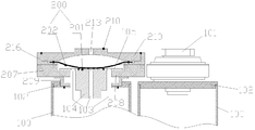
- FIG. 1 is a partially exploded perspective view of a power battery according to an embodiment of the present invention.
- FIG. 2 is a schematic top plan view of two adjacent single cells of the present invention.
- Figure 3 is a cross-sectional structural view taken from line A-A of Figure 2;
- FIG. 4 is a schematic exploded view showing a current interrupting device according to an embodiment of the present invention.
- Figure 5 is a schematic exploded view showing the flip member and the conductive member according to an embodiment of the present invention.
- Figure 6 is a cross-sectional structural view showing the flip member and the conductive member in an assembled state
- FIG. 7 is a schematic top plan view of a conductive member according to an embodiment of the present invention.
- Figure 8 is a cross-sectional structural view showing a pole and a ceramic ring according to an embodiment of the present invention.
- Figure 9 is a perspective view showing the structure of the pole of Figure 8.
- Figure 10 is a cross-sectional view showing the structure of a pole and a ceramic ring according to an embodiment of the present invention.
- Figure 11 is a perspective view showing the structure of the pole of Figure 10 and the ceramic ring;
- FIG. 12 is a schematic structural view of two adjacent single cells according to an embodiment of the present invention.
- Figure 13 is a perspective view showing the structure of a power battery according to an embodiment of the present invention.
- Figure 14 is a perspective view showing the structure of a unit cell according to an embodiment of the present invention.
- Figure 15 is a schematic exploded perspective view of a single cell of an embodiment
- Figure 16 is an exploded perspective view showing the inverted member and the conductive member of an embodiment
- Figure 17 is a partial cross-sectional structural view showing a single cell of an embodiment
- Figure 18 is a partial cross-sectional structural view showing a single cell of an embodiment of the present invention.
- Figure 19 is a schematic block diagram of a control system in accordance with one embodiment of the present invention.
- FIG. 20 is a schematic exploded view of a unit cell according to an embodiment of the present invention.
- FIG. 21 is a partial cross-sectional structural view of the unit cell of FIG. 20 after assembly;
- Figure 22 is a partial cross-sectional structural view showing a single cell of one embodiment of the present invention.
- FIG. 23 is a schematic structural diagram of a current interrupting device according to an embodiment of the present invention.
- Figure 24 is a partial cross-sectional structural view showing a unit cell of one embodiment of the present invention.
- orientation words such as “up, down, left, and right” are generally defined on the basis of the drawing directions of the corresponding drawings, and the "inside and outside” means Inside and outside of the contour of the corresponding part.
- the invention provides a technical solution of a current interrupting device, a single battery, a battery module, a power battery and an electric vehicle.
- the current interrupting device is disposed in the single battery, and the plurality of single cells are connected into the battery module in series or in parallel, and can be placed in the battery pack to form a power battery.
- various technical solutions provided in the present invention can be widely applied to other battery fields.
- the present invention relates to a single battery 100, 1100, 2100, 3100, 4100, which relates to a current interrupting device 200, 1200, 3200, 4200 and an explosion-proof valve 2200, and further relates to a power battery charging and discharging protection system. .
- the various embodiments are described in detail below with reference to the drawings.
- the present invention provides a battery module including a plurality of unit batteries 100, 1100, 2100, 3100, 4100, wherein the unit battery may include a housing, a battery core housed in the housing, and an electrode electrically connected to the battery core
- the single battery includes a current interrupting device 200, 1200, 3200, 4200 or an explosion-proof valve 2200.
- the current interrupting device or the explosion-proof valve is electrically connected to the electrode terminal, so that the current of the electrode terminal can be controlled by the action of the current interrupting device. Input and output. That is, the current interrupting device or the explosion-proof valve is in a state in which the battery cell is turned on in the normal state in the single cell, and at this time, the electrode terminal can normally input and output current, so as to complete the charging and discharging work of the single cell, and in a dangerous state. When, for example, the battery is overcharged, the current interrupting device or the explosion-proof valve can interrupt the current input and current output of the electrode terminal, thereby avoiding problems such as overcharging of the battery.
- the reliability of the current interrupt device is critical, that is, the current interrupt device is required to respond quickly.
- the current interruption device or the explosion-proof valve can also be fixed relative to the cover plate, that is, the current interruption device or the explosion-proof valve can be directly fixed on the cover plate, or can be fixed on any cover plate.
- the components that are connected or fixed relative to the cover are, for example, mounted on electrode terminals provided on the cover.
- the current interrupting device or the explosion-proof valve is a mechanical structure that induces air pressure.
- the current interrupting device is in gas communication with the inside of the casing of the unit cell and is capable of acting to interrupt the current flowing under the air pressure.
- the transfer of current can be interrupted by disconnecting the internal components, thereby cutting off the charge and discharge of the battery in time.
- the source of the air pressure utilized is: when, for example, the battery is in a dangerous state such as overcharging, gas is generated inside the battery, which causes the air pressure inside the outer casing to rise, or the battery temperature rises when the battery is abnormal during use causes the battery to rise.
- the internal air pressure rises, thereby generating the pneumatic power of the drive current interrupting device or the explosion-proof valve.
- Figures 1 through 12 provide some embodiments.
- the current interrupting device 200 has a conductive member 201 and a flip member 202 electrically connected to the conductive member 201, and the flip member 202 and the conductive member 201 can be disconnected under the action of air pressure.
- Electrical connection in the present invention, the manner of disconnecting the electrical connection may be different, wherein the connection point between the conductive member and the flip member may be disconnected, for example, the solder joint between the two is pulled off to realize the electrical connection.
- it is also possible to disconnect at least one of the two for example by machining a weak nick on the corresponding component to achieve the disconnection of the structure itself, thereby achieving the disconnection of the electrical connection. That is, in the present invention, the purpose of breaking the mechanical structure under the action of air pressure to cut off the transmission of current is achieved.
- the flip member 202 is electrically disconnected from the conductive member 201 by the flipping operation, thereby interrupting the electrode terminal 101. And the external circuit, stop charging the battery, so as to avoid the internal pressure of the battery continues to rise, to ensure the safety of the battery.
- the electrode terminal 101 includes a pole 104 electrically connected to the cell, for example connected to the cell by an inner lead, wherein the post 104 passes through the cap 102 to draw current from the housing.
- the current interrupting device 200 is mounted on the pole 104. In this way, the air pressure inside the battery can be directly felt through the pole 104, and the sensitivity is high, and the current interruption device 200 and the electrode terminal can be separately connected to facilitate the processing.
- the flip member 202 and the conductive member 201 are connected by a boss soldering structure, and the boss soldering structure includes a boss 203 and a connecting hole 204 for receiving the boss 203. And a ring-shaped solder joint 217 between the boss 203 and the connection hole 204.
- the boss 203 is formed on the conductive member 201, and the connecting hole 204 is formed on the flip member 202. More specifically, the flip member 202 is formed as a first sheet-like structure, and the first sheet-like structure is formed with the connecting hole 204.
- the conductive member 201 is formed as a second sheet-like structure, and the second sheet-like structure is formed with a boss 203.
- the boss 203 may also be disposed on the flip member 202, and the connecting hole 204 is disposed on the conductive member 201.
- the flip member 202 and the conductive member 201 may also be soldered by laser penetration welding or the like.
- the way of disconnecting the electrical connection between the flipping member and the conductive member can be realized by the scoring, that is, the weak portion having less strength than other regions is processed in the corresponding portion, wherein in order to complete the complete disconnection of the conductive member and the flip member, the engraving is completed.
- the mark typically surrounds the point of attachment of the conductive member and the flip member, such as the annular structure of the above-described boss welded structure.
- the conductive member 201 is formed with a score 205, the moment The mark 205 surrounds the connection point for connecting the flip member 202, that is, the conductive member 201 is provided with an annular score around the boss 203.
- the notch 205 can be pulled off, so that the portion of the boss 203 surrounded by the score 205 is separated from the conductive member 201 with the flip member 202, thereby realizing the current. Disconnected.
- a score can also be formed on the flipper 202.
- the score 205 is elliptical.
- the boss 203 is circular, and the center of the elliptical score 205 and the center of the boss 203 are shifted along the long axis direction of the ellipse. In this way, the area at both ends of the elliptical long axis can be unevenly stressed, thereby facilitating the pulling of the score 205 from the local point, thereby improving the sensitivity of the notch 205.
- the conductive member flip member 202 is disposed coaxially with the electrode terminal 101, and the conductive member 201 is disposed obliquely with respect to the axis of the electrode terminal 101.
- the lower position score can be first broken, thereby increasing the sensitivity of the score 205 being pulled off.
- the score 205 is elliptical
- the long axis of the elliptical design is inclined with respect to the axis of the conductive member, and is also inclined with the axis of the pole when the conductive member is mounted on the pole. Thereby, the region where the curvature of the long-axis end portion is large is first torn, thereby ensuring that the score 205 can be normally broken when necessary, and the current interrupting device 200 is normally operated.
- the score 205 is easily pulled off from the weakened hole 206, and the size and number of the weakened holes 206 can be set according to actual conditions.
- the weakened holes 206 are plural and spaced apart along the scores 205.
- the weakened hole 206 can also serve as a gas guide, so that gas inside the battery can exert a gas pressure on the flip member 202 through the weakened hole 206.
- the outer periphery of the flip member may be sealed, for example, by welding, to the cover plate so that the internal air pressure can force the flip member to break the score 205.
- the outer end and the inner end are defined relative to the outer casing in the axial direction of the pole, and the inner and outer sides of the ring, such as the outer circumference, are in the radial direction relative to Defined by the center of the ring.
- the score 205 thereon can also be broken.
- the outer end surface of the pole post 104 is formed with a receiving hole 218, the conductive member 201.
- the outer periphery is fixed to the inner wall of the receiving hole.
- the conductive member 201 can be stably fixed by the outer circumference of the ring, and the region inside the score 205 is not connected to the post 104 so as to be able to be broken by an external force such as the pulling force of the flip member 202 or the direct pressure of the gas.
- the current interrupting device 200 is in gas communication with the inside of the battery.
- the poles 104 and 104' are formed with air guiding passages communicating with the inside of the casing and the current interrupting device 200.
- air pressure is applied to the current interrupting device directly through the internal structure of the poles 104 and 104'. Make the structure simpler.
- the air guiding channel includes two air guiding holes 103, wherein the first air guiding hole 103 is configured to communicate with the receiving hole 218 and the inside of the housing, that is, directly to the conductive member. 201 applies pressure to break the score 205. That is, the air guiding passage includes air guiding holes 103 for communicating the above-described receiving hole 218 and the inside of the casing. The second air guiding hole 103 is for communicating the flip member 202 and the inside of the casing, thereby pressing the flip member to break the score 205. In order to increase the force efficiency of the flip member 202, the air guiding hole 103 is a plurality of surrounding the receiving hole. Therefore, the sensitivity of the current interrupting device can be increased by the combination of the two air guiding holes 103.
- the pole post 104' is fixedly coupled to the cap plate 102 to stabilize the electrode terminal structure.
- the outer periphery of the pole 104' has a radial boss 105 fixedly connected to the cover plate 102, and a second air guiding hole 103 is formed thereon to allow gas to flow to the flip member 202.
- the first type of air guiding holes 103 are formed in the poles 104' in the axial direction. That is, the air guiding hole 103 on the radial boss 105 is for pressing the flip member 202, and the air guiding hole 103 below the receiving hole 218 can directly press the conductive member 201. As shown in FIG.
- the radial boss 105 and the pole body of the pole 104' are formed with air guiding holes 103, wherein the first air guiding hole 103 and the end surface on the pole body are The receiving holes 218 are connected, and the number is four and are equally spaced in the circumferential direction. In other embodiments, the number of the first air guiding holes 103 may be other numbers, which is not limited in the present invention.
- the poles 104, 104', 104" need to be insulated from the cover plate while the cover plate is fixedly connected, and therefore, the poles 104, 104', 104"
- the fixed connection is made on a ceramic ring 207, 207' that is sealingly connected to the cover plate 102, for example by ceramic brazing.
- the reliability and weather resistance are stronger, and not only the stable sealing connection of the current interruption device but also the insulation of the two can be achieved.
- the outer periphery of the poles 104, 104', 104" has radial bosses 105, 105', and the inner edges of the ceramic rings 207, 207' have radial supports 208, 208' that support the radial bosses 105, 105', wherein the radial projections
- the stages 105, 105' are embedded in the ceramic rings 207, 207' and connected to the radial supports 208, 208', i.e., the radial supports 208, 208' are thinner to form a stepped receiving space for the poles 104, 104', 104" to be embedded.
- the radial bosses 105' and the radial supports 208' are respectively disposed in a plurality of circumferential intervals, that is, The radial bosses 105' are plural and circumferentially spaced apart, and the radial supports 208' are also plural and circumferentially spaced apart, and the plurality of radial bosses and the plurality of radial supports are in one-to-one correspondence.
- the ventilation can be realized by the interval between the adjacent radial bosses 105' and the radial support 208', the structure is simpler and more ingenious, and the processing is convenient, and no additional air guiding holes are needed on the poles 104", thereby
- the area of the pole piece 104" in which the conductive member 201 is assembled is not affected, and the size of the conductive member 201 can be maximized, thereby increasing the size of the score and ensuring the sensitivity of the pull-off.
- the radial bosses 105' are three at equal intervals to achieve connection stability and gas permeability.
- the number of radial bosses may also be other numbers, such as four or more.
- the outer end faces of the ceramic rings 207 and 207' are formed as a stepped structure having inner and outer rings, and the poles are 104, 104', 104" are embedded in the inner ring.
- the inner ring is formed as a unitary annular radial support, while in the split radial boss 105
- the inner ring forms a plurality of spaced apart radial supports 208' as described above, thereby making the overall structure more compact and the connection more stable.
- the outer end surface of the ceramic ring 207, 207' is sealingly connected with a conductive ring 216, specifically connected to the outer ring, and the outer periphery of the flip member 202 is fixedly connected to the conductive On the ring 216, that is, the flip member 202 is connected to the ceramic ring 207, 207' through a conductive ring, which can establish a current loop between the flip member and the outside.
- the current interruption is lost.
- the conductive ring 216 is sealingly connected to the outer ring of the ceramic ring to be insulated from the pole, that is, the poles 104, 104', 104" and the conductive ring 216 are insulated by the ceramic ring.
- the conductive ring 216 is sealingly connected to the ceramic ring. The outer periphery of the flip member is sealed so that the air pressure inside the outer casing can act on the flip member without leaking.
- the outer end surface of the conductive ring 216 is formed with an L-shaped opening, and the inner end surface thereof is used for connecting the outer ring of the ceramic ring.
- the outer periphery of the flip member 202 is embedded in the L-shaped opening, and the outer periphery is sealingly connected to the L-shaped opening by a cap 210 that covers the flip member 202.
- the conductive ring 216 can establish a current loop through the electrode lead-out piece connected to the cap or directly connected to the outside, for example, between the adjacent unit cells 100, or adjacent battery modules can be connected through the electrode lead-out piece.
- the inner end surface of the ceramic ring 207, 207' is sealingly connected with a transition ring 209, which can be connected to the ceramic ring 207, 207' by ceramic brazing, and the transition Ring 209 is sealingly attached to cover plate 102.
- the transition ring 209 can also be such that the ceramic rings 207, 207' are spaced from the cover plate 102.
- the ceramic rings 207, 207' are not directly assembled with the cover plate 102, the influence of the high temperature generated when the cover plate 102 is brazed by the ceramic ring can be avoided, and the area of the ceramic ring 207, 207' is not directly assembled due to the need to be directly assembled with the cover plate 102. It is limited and does not require special design, fabrication and assembly of the ceramic rings 207, 207'.
- the transition ring 209 has an inner ring and an outer ring forming a Z-shaped structure, and the cover plate 102 is formed with a through hole through which the poles 104, 104', 104" pass.
- the end surface of the through hole is a stepped structure, and the inner ring of the transition ring is embedded and supported in the step structure. That is, in FIG. 3, FIG. 8 and FIG. 10, the inner ring is located below and embedded in the through hole, thereby increasing the contact between the two. The area guarantees a stable connection.
- the outer circumference of the flip member 202 needs to be sealed, in particular, the ceramic ring 207, 207' is sealingly connected between the outer periphery of the flip member and the cover plate, thereby Stable and reliable operation of the current interrupting device is achieved by the sealing of the ceramic structure.
- the air pressure inside the outer casing can effectively act on the current The device is interrupted, thereby making the current interrupt device work reliably.
- the ceramic rings 207, 207' are respectively connected to the conductive ring 216, the poles 104, 104', 104" and the transition ring 209 by ceramic brazing, that is, the four components can be formed first. a separate assembly, and then the transition ring 209 is assembled to the cover plate 102 by laser welding, the assembly side It is not necessary to braze the ceramic ring directly onto the cover.
- the conductive member 201 and the poles 104, 104', 104" may be connected by laser welding, and the flip member and the conductive member may be connected by laser penetration welding or the above-mentioned boss soldering structure, and the cap 210 may be laser welded with the conductive ring.
- the poles 104, 104', 104" can be laser welded to the lead of the battery core to complete the assembly of the overall current interrupting device.
- the above mainly describes the structure of the current interrupting device 200, and the arrangement of the current interrupting device 200 will be described below.
- the 200-size design of the current interrupting device can be made larger, so that the pulling force can be increased by increasing the force receiving area when the air pressure is not variable.
- the area of the flip member is designed to be large to increase the breaking force of the flip member.
- the current interrupting device 200 is designed to extend radially out of the cover plate 102 to increase the size. In this case, in the battery module, there are a plurality of single cells 100.
- the current interrupting device 200 is offset from the adjacent electrode terminals in the extending direction of the cover. In this way, the area where the cover terminal 102 is not provided with the electrode terminal 101 can be fully utilized, so that the protruding current interrupting device does not interfere with the structure on the adjacent cover plate, the space inside the battery pack is sufficiently saved, and the energy density in the package body is improved. It should be noted that the meanings of the current interrupting device and the adjacent electrode terminal, or the electrode terminal and the adjacent electrode terminal between the adjacent single cells in the present invention and the following are different singles. The connection of adjacent features between the body cells, rather than the connection of adjacent features on the same unit cell.
- the current interrupting device 200 and the adjacent electrode terminals 101 are shifted from each other in the direction in which the cover plate extends. In other embodiments, the two may also be offset from one another in the height direction.
- the current interrupting device 200 and the adjacent electrode terminals are connected by an L-shaped connecting member 214, and the L-shaped connecting member 214 has a cover.
- the portion 211 and the lead portion 212 are covered and connected to the current interrupting device 200, and the lead portion 212 extends to the adjacent electrode terminal to be adjacent thereto.
- the L-shaped connecting member as shown in FIG. 1 is first aligned with the adjacent electrode terminal in the extending direction of the cover plate and then extended to the electrode terminal.
- the L-shaped connecting member may also first extend to Adjacent cover plates are then extended to the electrode terminals to achieve electrical connection.
- the current interrupting device 200 includes a cap 210 covering the flip member 202, the cap 210 extending along the cover plate 102 to the adjacent
- the electrode terminals are aligned, that is, have a cover portion 211 and a lead portion 212 which are arranged in a straight line, and are connected to adjacent electrode terminals by a linear type I-connecting member 215.
- the I-type connector 215 can also be used to connect the electrode terminals 101 of the current cell 100 without the current interruption device 200.
- the cap 210 of this shape can be used only in the overall battery module. This kind of connector can be.
- the width of the unit cell 100 in which the current interrupting device 200 is disposed is larger than the width of the unit cell in which the current interrupting device 200 is not provided, and the current interrupting device 200 approaches the cover plate 102.
- the edge of the width extends so that the adaptation of the current interrupting device 200 can likewise be achieved.
- the current interrupting device can be prevented from protruding from the cover plate, so that adjacent electrode terminals can be aligned with each other. This also prevents the current interrupting device 200 extending out of the cover plate 102 from affecting other structures such as the welded structure on the adjacent cover plate 102. And preferably, the current interrupting device and the adjacent electrode terminals may be connected by a linear type I connector 215.
- the cell capacity in the body battery 100 is the same, thereby avoiding the existence of a single cell of different capacities under the same module, and avoiding the influence on the BMS.
- the remaining space inside the casing can be filled with a partition, that is, the cell is filled with a partition to make the assembly structure of the cell stable.
- the ratio of the volume of the battery cell to the separator may be 1:1 to 2:1, wherein the separator may be made of an electrolyte resistant material.
- the number of the single cells of the current interruption device 200 may be no more than three; preferably, the current interruption is set.
- the number of the single cells of the device 200 is three; preferably, the single cells of the current interrupting device 200 are single cells located at the end and the central portion of the battery module; wherein, if the battery module includes n
- the single cells arranged at the end of the battery module are the first single cell of the battery module and the nth single cell of the battery module; when n is an odd number, the battery module
- the single cell in the central part of the group is the (n+1)/2 single cell of the battery module; when n is an even number, the single cell in the central part of the battery module is the first of the battery module n/2 single cells or (n+2)/2 single cells, where n ⁇ 3.
- the present embodiment provides a single cell 1100 including a housing, a battery core housed in the housing, an electrode terminal 1101 electrically connected to the battery core, and a package housing.
- a cover plate 1102 is provided on the cover plate 1102 for input and output of current.
- the unit cell 1100 further includes a current interrupting device 1200 in gas communication with the interior of the outer casing. Unlike the manner in which the electrode terminal is mounted on the electrode terminal according to the embodiment of FIGS. 1 to 12, the current interrupting device 1200 is disposed on the cover plate. Up and in gas communication with the interior of the housing, wherein the current interrupting device 1200 has a conductive member 1201 and a flip member 1202 electrically connected to the conductive member 1201.
- the flip member 1202 and the conductive member 1201 can be electrically disconnected under the action of air pressure. That is, the current interrupting device 1200 operates in substantially the same manner as the current interrupting device according to the embodiment of FIGS. 1 to 12, and both open the circuit by sensing the inversion of the inverting member by the air pressure in the single cell.
- the conductive member 1201 has a body portion 1299 connected to the flip member 1202 and extends from the body portion 1299 to the electrode terminal 1101 and is connected to the electrode terminal 1101.
- the connecting portion 1298 therefore, in the present embodiment, the current interrupting device 1200 is disposed on the cover plate, so that the height of the electrode terminal 1101 can be prevented from being increased, thereby increasing the electric power by utilizing the length space of the cover plate. Pool capacity density.
- the body portion 1299 of the conductive member 1201 is in gas communication with the inside of the casing and is formed with a score 1205 surrounding the connection point for connecting the flip member 1202. .
- the score can be pulled down by the internal air pressure, thereby breaking the electrical connection between the flip member and the conductive member.
- a vent hole 1206 is provided on the score 1205. In this way, not only can the air pressure be applied to the flip member 1202 through the vent hole 1206, but the pulling force is applied to the score through the flip member, and the housing 1205 can be easily pulled at the position of the vent hole 1206 to lift the flip member 1202.
- the effect of the sensitivity, this time mark can also be set on the flip member.
- the vent holes 1206 may be plural and spaced along the nick 1205. Further, for features such as scores and vent holes, the features in the embodiments according to Figs. 1 to 12 can be applied to the present embodiment.
- the body portion and the flip member of the conductive member may be respectively provided with a score.
- the score 1205 on the body portion can be pulled down by the first air pressure in the outer casing, the score on the flip member is sufficient to be pulled down by the second air pressure in the outer casing, and the second air pressure is greater than the first air pressure. That is, the strength of the score of the body portion of the conductive member is smaller than the strength of the score on the flip member to be able to be broken by the smaller first air pressure. Only when the air pressure continues to rise, continue to pull off the nick on the flipper and relieve pressure.
- the outer periphery of the inverting member 1202 is sealingly connected with the conductive member 1201 to prevent gas from leaking from the outer periphery of the inverting member to release pressure.
- the cover plate 1102 is provided with a vent hole in gas communication with the inside of the outer casing, and the cover plate is sealedly connected with a first ceramic ring 1207 surrounding the vent hole, and the body portion 1299 is sealingly connected to the first ceramic ring 1207, thereby The internal air pressure can be caused to act on the body portion 12299 without leaking.
- the outer peripheral edge of the flip member 1202 is sealingly coupled to the second ceramic ring 1296, and the second ceramic ring is sealingly coupled to the conductive member 1201. Therefore, by the insulating property of the second ceramic ring, both the outer periphery of the flip member 1202 can be stably supported, and the outer periphery of the conductive member and the flip member 1202 can be insulated by the second ceramic ring 1296, so that the flip member 1202 and the conductive member are 1201 can maintain the disconnection current connection after being broken by the nick 1205, thereby interrupting the current.
- the body portion 1299 of the conductive member 1201 is formed with an annular boss 1297 surrounding the score 1205, such that the structure of the annular boss 1297 is radially inward. It can be used to form features such as the score 1205, and the back recess of the annular boss 1297 can be sealed to accommodate the first ceramic ring 1207. In addition, the outer side of the annular boss 1297 can be used for sealingly supporting the second ceramic. Ring 1296.
- the unique structure of the conductive member described in FIGS. 16 and 17 enables a more convenient mounting of the current interrupting device 1200.
- first ceramic ring 1207 is sealingly connected to the cover plate 1102 by a transition ring 1209 having a connecting body embedded in the inner wall of the vent hole and a flange ring for connecting the first ceramic ring 1207 as shown in FIG. .
- the flange ring projects radially from the connecting body and fits over the cover. Thereby ensuring the stability of the current interrupting device 1200 The mounting is not required, and the first ceramic ring 1207 is directly connected to the cover 1102.
- the electrode terminal 1101 in order to facilitate the connection, preferably, as shown in FIG. 17, the electrode terminal 1101 includes a pole 1104 that passes through the cap plate 1102 and is electrically connected to the cell. As shown in FIGS. 14 and 16, the connecting portion 1298 of the conductive member 1201 is formed with a slot 1295 through which the post 1104 is inserted and welded to each other to achieve a stable connection therebetween.
- the current interrupting device 1200 includes a connector 1210 overlying the flip member 1202 and electrically connected to the flip member 1202, the connector member 1210 having a cover portion 1294 covering the flip member 1202 and from the cover portion 1294 extends out of the lead portion 1293.
- the connecting member 1210 can be formed in the same structure as the L-shaped connecting member 214 in the embodiment according to FIGS. 1 to 12, that is, the covering portion and the lead portion are formed as an L-shaped connecting member. Thereby, it is convenient to draw current from the current interrupting device 1200 to the outside of the adjacent electrode terminal or module.
- the current interrupting device extends the cover plate in the radial direction, thereby increasing the force receiving area and increasing the breaking force. Between adjacent cells, the current interrupting device and the adjacent electrode terminals are offset from each other in the direction in which the cover plate 1102 extends, thereby avoiding interference with the structure on the adjacent cover plates. Also in the same manner as the embodiment according to FIGS. 1 to 12, the number of unit cells 1100 provided with the current interrupting device 1200 is not more than three.
- a unit cell 2100 according to an embodiment of the present invention is described below with reference to FIG. 18, comprising a housing, a battery core housed in the housing, an electrode terminal 2101 electrically connected to the battery core, and a cover plate 2102 for encapsulating the housing, the electrode The terminal 2101 is disposed on the cover plate 2102, wherein the unit cell includes a first electrode lead-out member 2298 electrically connected to the battery core, and a second electrode lead-out member 2297 electrically connected to the electrode terminal 2101, and the cover plate 2102 is further provided with An explosion-proof valve 2200 is connected to the inside of the outer casing, and the explosion-proof valve 2200 has a reversing member 2202 that connects the first electrode lead-out member 2298 and the second electrode lead-out member 2297, that is, the two electrode lead-out members are connected by the flip member 2202.
- the first electrode lead-out member 2298 and/or the second electrode lead-out member 2297 are formed with a first score 2205, which can be broken under the air pressure in the outer casing to interrupt the first electrode lead-out member 2298. And/or the current on the second electrode lead-out member 2297, that is, the effect of the first score is to cause the electrode lead-out member provided there to be broken to interrupt the transfer of current, so that at least one of the two electrode lead-out members is provided with A nick can achieve the disconnection of the electrical connection between the cell and the electrode terminal, which in turn causes the cell to be disconnected from the outside.
- the flip member 2202 is further provided with a second score 2299, which can be broken under the air pressure in the outer casing to allow the gas in the outer casing to leak out through the flip member 2202, that is, the second moment.
- the role of the mark is to ventilate, and after the disconnection, the internal gas can be leaked, thereby preventing the internal pressure of the battery from continuing to rise and causing an explosion to play an explosion-proof role.
- the first score can be pulled down by the first air pressure in the outer casing
- the second score can be pulled down by the action of the second air pressure in the outer casing
- the second air pressure is greater than the first air pressure. That is, the intensity of the first score 2205 is less than the score of the second score 2299 to be able to be broken by the smaller first air pressure. Only when the air pressure continues to rise continues to pull off the second score 2299 and relieve pressure.
- the two electrode lead-out members may have a long piece structure, so that The current is applied, and the first score 2205 extends from one side edge to the other side edge in the width direction of the long sheet structure, so that the long sheet structure can be broken along the first score in a more timely manner.
- the flip member 2202 may be formed with an annular outer wall, and the two electrode lead members may be fixedly connected to the annular outer outer wall to achieve current transfer.
- the annular outer wall of the inverting member may be formed by, for example, a boss in the boss welding structure, and the inverting member is further formed with a taper ring structure that extends obliquely outward from the boss to the flip The outer periphery of the piece to form a flip-shaped member in the shape of a bowl.
- the second indentation may be formed in a ring structure around the circumferential direction of the inverting member to completely break under the action of air pressure, thereby increasing the gas pressure relief efficiency.
- a second score can be formed on the cone ring structure.
- the outer peripheral edge of the inverting member 2202 is relatively fixedly insulated from the cover plate, so as to avoid the gas from being pulled off. In the case of a nick and a second nick, the two nicks are rendered ineffective. On the other hand, the cover can be prevented from being charged by an insulated connection.
- the electrode terminal 2101 includes a pole that passes through the cover plate, and the pole is insulated from the outside of the cover plate by a second ceramic ring to facilitate establishing a current loop with the outside. That is, current transfer between adjacent cells is achieved by interconnection of the electrode terminals.
- the ceramic ring can prevent the cover from being charged.
- the first ceramic ring 2207 is sealingly connected between the outer periphery of the flip member 2202 and the cover plate, and also functions as a seal and insulation.
- the cover plate 2102 is fixedly connected with a first transition piece 2295, and the outer periphery of the flip member 2202 is fixedly connected with a second transition piece 2296.
- the first transition piece and the second transition piece may be aluminum pieces.
- the first transition piece 2295 and the second transition piece 2296 are brazed coaxially with the first ceramic ring 2207. In this way, when assembling, the two transition sheets can be first brazed to the first ceramic ring, and then the two fixing pieces are welded to other structures, thereby avoiding the first ceramic ring and the cover plate, etc.
- the high temperature and the like generated by brazing between the structures facilitates assembly and achieves a sealed, stable, and insulated connection through the first ceramic ring 2207, and can prevent the cover 2102 from being charged.
- first transition piece 2295 and the second transition piece 2296 may each have an annular structure to accommodate the two annular end faces of the first ceramic ring.
- the cover plate 2102 is formed with an annular boss, and the first transition piece 2295 is supported on the annular boss, and the first ceramic ring abuts against the inner wall of the annular boss toward the second transition piece 2296. The first ceramic ring is thereby stably connected within the cover 2102.
- the explosion-proof valve further includes a protective film 2099 that can be broken by air pressure, and the protective film seals over the flip member 2202, specifically, the first transition piece 2295 that is remote from the flip member.
- the protective film 2099 can normally protect the inside of the explosion-proof valve 2200, and when explosion-proof is required, it can be broken by a certain air pressure, for example, the second air pressure, thereby avoiding the explosion-proof effect of the explosion-proof valve.
- the ratio of the residual thickness of the first score to the residual thickness of the second score is 1:3-1:1.2. Further, it is 1:2-1:1.3.
- the unit cell 3100 includes a housing, a battery core housed in the housing, a cover plate 3102 of the package housing, and an electrode terminal 3101 disposed on the cover plate 3102, wherein the unit battery 3100 further includes an electrical connection with the battery core.
- the embodiment of FIG. 12 is mounted on the outer end of the pole.
- the current interrupting device 3200 in this embodiment is located inside the cover plate 3102 and is in gas communication with the inside of the casing to be able to disconnect the current flowing under the action of air pressure.
- An adapter 3298 extending radially outward from the outer periphery is connected to the electrode terminal 3101 to connect the outer periphery of the current interrupting device through the adapter 3298.
- the current interrupting device connected to the radially outer side of the adapter member 3298 can be designed in such a manner as to be directly connected to the electrode terminal.
- increasing the adapter and increasing the size of the current interrupting device are advantageous for the transmission of a large current.
- the adapter 3298 is formed in an annular structure, the inner circumference of the annular structure is connected to the outer circumference of the electrode terminal, and the outer circumference is connected to the outer circumference of the current interrupting device, thereby increasing the area of the current interruption device.
- the adapter 3298 can also be a structure of a plurality of connecting posts extending in the radial direction and spaced apart in the circumferential direction, and can also achieve the effect of increasing the area of the current interrupting device.
- the inner circumference of the annular structure cooperates with the outer peripheral end of the inner end of the electrode terminal.
- a stopper may be formed on the outer periphery of the inner end of the electrode terminal, and the inner circumference of the adapter is embedded in the opening and connected, thereby increasing the connection area and increasing the current transfer efficiency while ensuring the connection stability.
- the inner and outer ends of the electrode terminal are defined in the axial direction thereof with respect to the outer casing, that is, the inner end is close to the inner portion of the outer casing.
- the outer periphery of the annular structure protrudes toward the inside of the outer casing, that is, the annular structure itself is formed into a ring cap structure, and the current interrupting device is engaged with the inner end opening of the outer peripheral edge, thereby Not only does the connection ensure a stable increase in current transfer efficiency but also the current interrupting device and the electrode terminals can be spaced apart, thereby providing space for the current interrupting device to be disconnected under the action of air pressure.
- the inner lead-out member 3299 includes a connecting piece (not shown) connected to the battery core, the connecting piece extending from the battery core toward the cover plate.
- the inner lead-out member further includes a support groove for accommodating the installation current interrupting device, and a connecting plate extending from the support groove toward the opposite direction, and the connecting plate is respectively insulated from the cover plate, thereby preventing the cover plate from being charged, in particular, the connecting plate
- the connecting groove can be formed as an integral sheet structure, that is, the connecting groove comprises two side walls and a bottom wall, and the two side walls are respectively connected with the connecting plates on both sides.
- the bottom wall of the supporting groove may be formed with an air vent formed in gas communication with the inside of the casing.
- the inner lead-out member 3299 is insulatively connected to the inner side of the cover plate 3102 by the ceramic member 3296.
- the ceramic member 3296 can be formed as a ceramic piece, and is respectively welded to the inner lead-out member 3299 and the cover plate through the transition piece 3294, that is, the transition piece 3294 is two pieces, and the transition piece can be an aluminum piece, respectively located on the ceramic piece 3296.
- the upper and lower surfaces, the ceramic member 3296 is welded to the cover plate 3102 through the transition piece 3294 on the upper surface of the ceramic member 3296, and the ceramic member 3296 is also welded to the inner lead member 3299 through the transition piece 3294 located on the lower surface of the ceramic member 3296, thereby
- the welded connection between the ceramic member 3296 and the cover plate 3102 and the inner lead-out member 3299 is made easier, and the welded structure is stable.
- the ceramic piece 3296 and the transition piece on the upper and lower surfaces thereof The 3294 can be connected by ceramic brazing.
- the transition piece 3294 on the upper surface of the ceramic member 3296 and the cover plate 3102 can be connected by laser welding.
- the transition piece 3294 located on the lower surface of the ceramic member 3296 can be connected between the transition piece 3294 and the inner lead-out member 3299. Connected by laser welding.
- the current interrupting device 3200 has a conductive member 3201 and a flip member 3202 connected to the conductive member 3201 to be electrically connected to each other, and the flip member 3202 and the conductive member 3201 can be electrically disconnected under the action of air pressure, wherein the conductive member is electrically conductive.
- the member 3201 is connected to the inner lead-out member 3299 and formed with an air guiding hole 3213 in gas communication with the inner portion of the outer casing.
- the conductive member 3201 is embedded in the supporting groove of the inner lead-out member, so that the through-air hole formed in the supporting groove can be guided.
- the air holes 3213 are in gas communication such that the inverting member 3202 can sense the internal gas of the outer casing to open the electrical connection of the inverting member 3202 and the conductive member 3201 under the action of the internal air pressure.
- the outer circumference of the flip member 3202 is connected to the outer circumference of the adapter 3298 to establish a current connection path.
- the conductive member 3201 is formed with a score which is disposed around a connection point for connecting the flip member 3202.
- the score is broken to break the electrical connection between the conductive member and the flip member.
- the scores may also be formed on the flip member or in a manner that pulls off the joint points.
- the outer periphery of the flip member 3202 is supported and connected to the conductive member 3201 and/or the inner lead member 3299 via the insulating member 3295, so that the assembly of the flip member 3202 is realized by the insulating member 3295, so that It can be ensured that the outer peripheral edge of the flip member is insulated from the inner lead-out member 3299 and the conductive member, thereby preventing the flip member from being electrically connected to the conductive member or the inner lead member at the outer peripheral edge after being electrically disconnected from the conductive member under the action of air pressure.
- the insulating member may be an annular insulating member such as a ceramic ring or a sealing ring, wherein the insulating member has three connection manners, and the first is sealed and supported on the conductive member 3201, specifically, the supporting member is pulled around the conductive member 3201. The second region is supported on the inner lead-out member 3299, and the third member is supported on the inner lead-out member 3299 and the conductive member 3201. As shown in Fig. 23, the insulating member is supported on the joint region of the inner lead member 3299 and the conductive member 3201.
- the flip member 3202 and the conductive member 3201 are connected by a boss soldering structure surrounded by a notch 3205, the boss soldering structure including a boss 3203, a connecting hole 3204 accommodating the boss 3203, and a connection at the boss 3203
- the annular solder joints 3217 between the holes 3204 ensure efficient passage of large currents.
- FIG. 23 unlike the one shown in FIG.
- the boss 3203 is formed on the flip member 3202, and the connection hole 3204 is formed on the conductive member 3201. Further, as in Fig. 6, the boss may be formed on the conductive member 3201, and the connecting hole 3204 may be formed on the flip member.
- the conductive member 3201 may be formed as a cap-like structure including a cap body connected to the flip member and a cap surrounding the cap body, wherein the cap hole is formed with the air guiding hole and is led out The pieces are connected, and the cap protrudes toward the flip member, the flip member is formed into a sheet-like structure, and the insulating member 3295 is connected between the outer periphery of the sheet structure and the cap. Therefore, the current interrupting device provided by the present invention has a compact structure and stable assembly.
- the electrode terminal 3101 in order to establish a current loop with the outside world, preferably, the electrode terminal 3101 includes a pole 3104 passing through the cover plate, and the pole is insulated from the cover plate through the ceramic ring 3293, thereby avoiding charging of the cover plate.
- Connect A member 3298 is attached to the inner end of the pole to establish a current loop with the outside by exposing a portion outside the cover.
- the ceramic ring 3293 is sealingly attached to the outer surface of the cover plate and is sealingly connected to the pole 3104 to ensure a sealing effect inside the cover.
- the air hole 3292 is formed in the axial direction through the pole.
- the pressure of the closed cavity in the cover plate is not affected, but the pressure difference can be established with the outside atmosphere, so that the flip member 3202 can be operated under the action of the internal and external pressure difference. And the nick is broken 3205.
- the embodiment provides a unit battery 4100 and a battery module using the same, wherein the unit battery 4100 includes a housing, a battery core housed in the housing, an electrode terminal 4101 electrically connected to the battery core, and a package a cover plate 4102 of the outer casing, the electrode terminal 4101 is disposed on the cover plate 4102, wherein the electrode terminal includes a pole 4104 that passes through the cover plate 4102 and is electrically connected to the battery core through the inner lead-out member 4196, and the single battery further includes a pole mounted
- the current interrupting device 4200 on the column 4104 has a flip member 4202 fixed relative to the cover plate 4102 and in gas communication with the interior of the housing, and the flip member 4202 is connected to the outer end surface of the pole 4104 by a connection point.
- the connection point can be disconnected under the action of air pressure.
- the current interruption device of the present embodiment operates on the principle that the connection point between the flip member 4202 and the pole 4104 is directly pulled by the air pressure, thereby interrupting the electrical
- the flip member 4202 is connected to the pole by a single pad 4199.
- the solder joint 4199 which is completed by spot welding can also be realized by other welding means such as laser welding. Therefore, in the present embodiment, the control of the breaking pressure can be realized by rationally implementing the penetration and the melting width of the solder joint.
- the pole 4104 is formed with an air guiding hole 4103 communicating with the inside of the outer casing, so that the internal air pressure can be easily guided to the current interrupting device.
- the flip member 4202 is formed with a score 4205 which is disposed around the connection point.
- the interruption of the current can be achieved by breaking the score 4205.
- the connection point and the squeezing pull-off gas pressure are different.
- connection point can be pulled down by the first air pressure in the outer casing, and the nick 4205 can be pulled down by the action of the second air pressure, the second air pressure. Greater than the first air pressure.
- the score 4205 can be used as a backup measure of the connection point to ensure the safety of the battery.
- the flip member 4202 is covered with a cap 4210 having a vent 4197 formed therein.
- the first ceramic ring 4207 is connected between the pole 4104 and the cover 4102, so that the stable mounting of the poles is achieved by the ceramic structure and at the same time the cover 4102 is prevented from being charged.
- a second ceramic ring 4198 is sealingly connected between the pole 4104 and the outer periphery of the flip member, so that the outer periphery of the flip member can be sealed by the ceramic structure, thereby ensuring that the inner gas can effectively press the flip member, and at the same time Ensure that the poles and the outer periphery of the flipper are insulated from each other, so that the flipper after the joint or the score is broken can still conduct electricity.
- the pole 4104 has an annular boss 4297 surrounding the connection point, and the back recess of the annular boss 4297 is sealed to receive the first ceramic ring 4207, and the first ceramic ring 4207 is sealedly connected
- a radially outer side of the annular boss 4297 is sealed and supported by a second ceramic ring 4198.
- the second ceramic ring 4198 The outer periphery of the support flip member 4202 is sealed.
- the structure of the overall current interrupting device is made more compact and the assembly is stable.
- the first ceramic ring 4207 is sealingly attached to the cover 4102 by a transition ring 4209. Specifically, it can be hermetically connected by ceramic brazing of the transition ring and the first ceramic ring 4207.
- the embodiment provides a unit cell including a housing 109, a battery core 108 housed in the housing 109, an electrode terminal 101 electrically connected to the battery core 108, and a cover plate 102 enclosing the housing, the electrode terminal The 101 is disposed on the cover plate 102.
- the electrode terminal includes a pole 105"' that passes through the cover plate 102 and is electrically connected to the battery core.
- the unit battery further includes a current interrupting device 200 mounted on the pole 104"'.
- the interrupting device 200 is in gas communication with the inside of the casing, wherein the current interrupting device 200 has a conductive member 201 and a flip member 202 connected to the conductive member 201 to be electrically connected to each other, and the flip member 202 and the conductive member 201 can be disconnected under the action of air pressure.
- the boss soldering structure includes a boss 203, and the boss 203 is accommodated
- the connecting hole 204 and the annular solder joint 217 between the boss 203 and the connecting hole 204, the inverting member 202 is formed as a first sheet-like structure, and the first sheet-like structure is formed with a connecting hole 204, and the conductive member 201 is formed as Second piece
- the second sheet-like structure is formed with a boss 203.
- the conductive member 201 is formed with a notch 205.
- the score 205 is disposed around the boss 203, and the conductive member 201 is connected to the outer end surface of the pole 104"'.
- the outer periphery of the flip member 202 is fixed relative to the cover plate 102, the pole post 104"' is fixedly coupled to the cover plate 102, and the pole post 104"' is formed with an air guiding passage communicating with the inside of the outer casing and the current interrupting device 200.
- the column 104"' is mounted on the ceramic ring 207" sealingly connected to the cover plate 102.
- the outer end surface of the ceramic ring 207" is sealingly connected with a conductive ring 216'.
- the outer periphery of the flip member 202 is sealingly connected to the conductive ring 216'.
- the upper post 104"' is insulated from the conductive ring 216' by a ceramic ring 207", thereby stably completing the transfer and interruption of current.
- the outer end surface of the pole post 104"' is formed with a receiving hole 218', and the outer peripheral edge of the conductive member 201 is fixed to the inner wall of the receiving hole.
- the score 205 is elliptical
- the boss 203 is circular
- the center of the score 205 and the center of the boss 203 are staggered along the long axis direction of the ellipse
- the long axis and the electrode of the ellipse The axis of the terminal is tilted.
- the inner edge of the ceramic ring 207" has a radial support 208" that supports the radial boss 105
- radial The bosses 105" are a plurality of circumferentially spaced apart ones
- the radial supports 208" are a plurality of circumferentially spaced apart ones
- the plurality of radial bosses and the plurality of radial supports are in one-to-one correspondence.
- the outer end surface of the ceramic ring 207' is formed as a stepped structure having an inner ring and an outer ring, the pole post 104"' is embedded in the inner ring, and the outer ring is sealed and connected with a conductive ring insulated from the pole.
- the outer periphery of the flip member 202 is fixedly connected to the conductive ring 216 ′, and the inner end surface of the ceramic ring 207 ′′ is sealingly connected with a transition ring 209 ′, and the transition ring 209 ′ is sealingly connected to the cover plate 102 to make the ceramic
- the ring 207" is spaced from the cover plate 102.
- the ceramic rings 207" are respectively sealed to the conductive ring 216', the poles 104"' and the transition ring 209' by ceramic brazing.
- the transition ring 209' has an inner ring and an outer ring forming a Z-shaped structure, and the cover plate is formed with a supply pole
- the through hole passes through the through hole, the end surface of the through hole is a stepped structure, and the inner ring of the transition ring is embedded and supported in the stepped structure.
- the outer end surface of the conductive ring 216' is formed with an L-shaped opening
- the outer periphery of the flip member 202 is embedded and supported in the L-shaped opening
- the outer periphery is sealed by the cap 210 covering the flip member 202. Connected to the L-shaped stop.
- the battery core 108 is connected with a lower spacer 107, and the upper spacer 106 is connected below the cover 102, and the upper and lower spacers can be made of an insulating material.
- the unit cell 100 further includes an inner connecting piece 110 connected to the battery core.
- the inner connecting piece 110 extends between the upper spacer 107 and the lower spacer 106.
- the lower surface of the pole 104"' is formed.
- the battery module includes a plurality of single cells, at least one of the single cells is the single cell, and the current interrupting device 200 extends radially outward from the cover 102, adjacent to each other. Between the unit cells 100, the current interrupting device 200 is offset from the adjacent electrode terminals in the extending direction of the cover. In addition, as shown in FIG. 1, between the adjacent unit cells 100, the current interrupting device 200 and the adjacent electrode terminals are connected by an L-shaped connecting member 214 having a covering portion 211 and The lead portion 212 is covered and connected to the current interrupting device 200, and the lead portion 212 extends to the adjacent electrode terminal.
- the embodiment further provides a power battery, comprising: a package body and a battery module housed in the package body; the battery module is the battery module, and the package body is provided for detecting A gas detecting device for combustible gas, the gas detecting device being disposed adjacent to the current interrupting device for providing a combustible gas signal for the charge and discharge protection system.
- the battery module has a current interrupting device.
- the above describes a single cell with a current interrupting device or an explosion-proof valve, in which the current interrupting device or the explosion-proof valve is a safety measure achieved by its own mechanical structure.
- the present invention will detail a power battery including a charge and discharge protection system to improve safety by electronic control.
- the present invention provides a power battery which may be the above-described power interrupting device, explosion-proof valve or other type of power battery.
- the power battery includes a package body and a plurality of unit cells 100 housed in the package body, wherein the plurality of unit cells 100 form a battery module, for example, in series or in parallel, wherein the package body is provided for detecting
- the charging and discharging protection system included in the power battery includes a control device 400 and a circuit switching device in addition to the gas detecting device 300 located in the power battery.
- the gas detecting device 300 feeds back the combustible gas signal to the control device 400, and the control device 400 is configured to cut off the charging and discharging circuit of the power battery according to the combustible gas signal control circuit switching device. That is, the safety of the present invention is an automatic control performed by detecting the presence or absence of a combustible gas in the inside of the bag. Among them, in the dangerous state in which the battery is overcharged, a combustible gas is generated inside, and this part of the gas may leak into the bag body more or less in various ways, and at this time, the gas detecting device, such as the gas sensor, can detect the combustible gas.
- control equipment Whether or not to cut off the charging and discharging circuit of the power battery is determined depending on whether or not the amount of combustible gas or the detected combustible gas is detected.
- the circuit switching device can be controlled to cut off the charging and discharging circuit of the power battery to ensure the safety of the power battery.
- the power battery further includes an alarm device 500 controlled by the control device 400, so that an alarm device such as a voice, a flashing light, a siren, etc. can be used to prompt the relevant personnel to evacuate the site, thereby reducing the safety hazard.
- an alarm device such as a voice, a flashing light, a siren, etc.
- the control device 400 includes a host computer main control chip 401 of a power battery and a control module 402 connected to the main control chip signal.
- the control module 402 is connected to the circuit switching device signal.
- the circuit switching device may be a relay 403 located in the charging and discharging circuit to be controlled by the control module 402 to cut off the charging and discharging circuit.
- the alarm device 500 may directly connect with the upper computer control chip 401 to receive an alarm command alarm.
- the collected signals of the gas sensor can be processed by digital-to-analog conversion, sampling and saving, etc.
- the fault diagnosis of the system can be performed.
- the collected signal can be further subjected to gas concentration.
- the process determines whether a leakage of combustible gas has occurred.
- the host computer main control chip 401 performs an operation of cutting off the current and the alarm.
- the gas detecting device is disposed outside the unit cell, and the combustible gas can be leaked out by the above-mentioned current interrupting device or the nick in the explosion-proof valve, and as long as the gas can be vented, It can be vented by various conventional explosion-proof valves known to those skilled in the art. That is, in the battery module, at least one of the unit cells is provided with a current interrupting means for cutting off the charge and discharge circuit under the action of the gas pressure inside the unit cell, that is, the respective current interrupting means. And the current interrupting device can allow the gas in the outer casing to be leaked in the cut-off state.
- the gas detecting device in the bag body can detect the leaked combustible gas, and at this time, it indicates that the battery has a dangerous situation such as overcharging.
- the gas detecting means is disposed adjacent to the current interrupting means, so that the corresponding signal can be detected in time and fed back to the control means after the flammable gas is released.
- at least one of the single cells is provided with an explosion-proof valve capable of venting gas under the gas pressure inside the single cell, such as the explosion-proof valve according to the embodiment of FIG. At this time, the gas detecting device may be disposed adjacent to the explosion-proof valve.
- the current interrupting device in each of the above embodiments has a cover member having a vent hole formed therein to allow the gas in the outer casing to be leaked after the flip member and the conductive member are electrically disconnected.
- the air holes on the cover member can also cause the current interrupting device to directly establish a pressure difference with the atmosphere, thereby realizing the action of the flip member.
- the cover member here may be the cap 210 according to the embodiment of FIGS. 1 to 12, or may be the connector 1210 according to the embodiment of FIGS. 13-17, or in the embodiment according to FIG. Protective film 2099 and the like.
- the gas can be made to escape by, for example, the air holes 213 in the embodiment of Figs. 1 to 12, thereby detecting the combustible gas leaking into the bag in time by the gas detecting means.
- the development of new energy vehicles has become the country's new strategic plan, and the hybrid or pure electric vehicles in the new energy vehicles occupy the mainstream in the current automotive market.
- the cruising range is currently It is the main factor restricting development, and it depends on the energy density of the battery.
- the main battery materials in the market are two camps of ternary and lithium iron phosphate.
- the former has high energy density, but the safety performance is poor, especially overcharge. It can cause a fire and explosion, which is a big challenge for the automotive industry where safety performance is critical.
- the existing battery pack design basically controls the voltage and current temperature of the battery cells in the module through the BMS (Battery Management System), but in the actual use process, the consistency and management software of the battery core.
- BMS Battery Management System
- the general public may also have a situation in which the vehicle body is plugged into a power source and charged all the time.
- BMS software for control, the single battery is charged for a long time, if the software detects Failure or other anomalies can create a risk of overcharging of the cells in the package loop.
- a mechanical protection design can be designed for the battery to avoid battery safety risks caused by software failure.
- the inventors of the present invention have creatively found that the current interruption timing of the battery in a dangerous state such as overcharging is actually regular, that is, the internal pressure can be utilized when a dangerous state such as overcharging occurs.
Abstract
本发明公开了一种单体电池、电池模组、动力电池及电动汽车。该单体电池(100)包括外壳、容纳在外壳内的电芯、与该电芯电连接的电极端子(101)以及封装外壳的盖板(102),电极端子(101)设置在盖板(102)上,电极端子包括穿过盖板(102)并与电芯电连接的极柱(104),单体电池还包括安装在极柱(104)上的电流中断装置(200),该电流中断装置(200)与外壳的内部气体连通,其中电流中断装置(200)具有导电件(201)和与该导电件(201)相连以相互电连接的翻转件(202),并且翻转件(202)与导电件(201)能够在气压作用下断开电连接,其中导电件(201)连接在极柱(104)上以相互电连接。
Description
本发明涉及电池领域,具体地,涉及一种单体电池、包括该单体电池的电池模组、包括该电池模组的动力电池和包括该动力电池的电动汽车。
电池作为储能单元在各行各业均有重要作用,例如动力电池广泛用于新能源汽车等领域,其中动力电池的电池包内可以具有由多个单体电池相互串联或并联成电池模组以实现充放电的工作。其中,动力电池在充放电过程中,通常通过BMS(电池管理系统)监控电压和电流的变化计算荷电态。如果电压采样出现问题,就可能导致电池过充,特别是对于三元体系来说,如过充达到一定程度更会出现电池燃烧爆炸的危险。
现有的技术方案:对电池的电压和电流的监测,通过电流积分法和开路电压法计算电池电量,并以此控制电池的充放管理。但是也存在不足,例如电池电压采样或者电流采样失效,或者软件失效,导致电池长时间充电得不到控制,特别是在充电桩充电的情况下,充电桩与电池管理器通讯失效时,过充无法控制,电池过充到一定程度,会引起电池鼓涨甚至爆炸起火。
因此,提供一种能够自身能够强制断开的电流中断技术具有积极意义。
发明内容
本发明的目的是提供一种单体电池,该单体电池能够在危险状态下强制断开电路从而避免电池爆炸等危险发生。
本发明的目的还在于提供一种使用该单体电池的电池模组,使用该电池模组的动力电池和使用该动力电池的电动汽车。
为了实现上述目的,本发明提供一种单体电池,该单体电池包括外壳、容纳在外壳内的电芯、与该电芯电连接的电极端子以及封装所述外壳的盖板,所述电极端子设置在所述盖板上,所述电极端子包括穿过所述盖板并与所述电芯电连接的极柱,所述单体电池还包括安装在所述极柱上的电流中断装置,该电流中断装置与所述外壳的内部气体连通,其中所述电流中断装置具有导电件和与该导电件相连以相互电连接的翻转件,并且所述翻转件与所述导电件能够在气压作用下断开电连接,其中所述导电件连接在所述极柱上以相互电连接。
可选地,所述翻转件与所述导电件通过凸台焊接结构相连,该凸台焊接结构包括凸台、容纳该凸台的连接孔以及位于该凸台和连接孔之间的环形焊点。
可选地,述翻转件形成为第一片状结构,该第一片状结构形成有所述连接孔,所述导电件形成为第二片状结构,该第二片状结构上形成有所述凸台。
可选地,所述导电件上形成有刻痕,该刻痕围绕用于连接所述翻转件的连接点设置。
可选地,所述刻痕为椭圆形,所述连接点为圆形连接点,并且所述刻痕的圆心与所述连接点的圆心沿所述椭圆形的长轴方向错开。
可选地,所述翻转件与所述电极端子同轴设置,所述导电件相对于所述电极端子的轴线倾斜设置。
可选地,所述导电件连接在所述极柱的外端端面上,所述翻转件的外周缘相对于所述盖板固定。
可选地,所述极柱的外端端面上形成有容纳孔,所述导电件的外周缘固定在该容纳孔的内壁上。
可选地,所述极柱安装在密封连接于所述盖板上的陶瓷环上。
可选地,所述陶瓷环的内端面上密封连接有过渡环,该过渡环密封连接在所述盖板上以使得所述陶瓷环与所述盖板间隔设置。
本发明还提供一种电池模组,该电池模组内设置有本发明提供的单体电池。
本发明还提供一种动力电池,包括包体和设置在该包体内的电池模组,其特征在于,所述电池模组为本发明提供的电池模组。
本发明还提供一种电动汽车,该电动汽车设置有本发明提供的动力电池。
通过上述技术方案,在电池出现危险时,电池内会产生气体,因此随着气压的升高,翻转片可以在气压作用下翻转以断开与导电件的连接,从而断开电池的充放电电路,继而避免电池气压继续增高而爆炸。
本发明的其他特征和优点将在随后的具体实施方式部分予以详细说明。
附图是用来提供对本发明的进一步理解,并且构成说明书的一部分,与下面的具体实施方式一起用于解释本发明,但并不构成对本发明的限制。在附图中:
图1是本发明一个实施例的动力电池的部分分解立体示意图;
图2是本发明的相邻两个单体电池的俯视结构示意图;
图3是从图2中的线A-A截取的剖视结构示意图;
图4是本发明一个实施例的电流中断装置的分解结构示意图;
图5是本发明一个实施例的翻转件和导电件的分解结构示意图;
图6是一个实施例的翻转件和导电件装配状态下的剖视结构示意图;
图7是本发明一个实施例的导电件的俯视结构示意图;
图8是本发明一个实施例的极柱与陶瓷环的剖视结构示意图;
图9是图8中的极柱的立体结构示意图;
图10是本发明一实施例的极柱与陶瓷环剖视结构示意图;
图11是图10极柱与陶瓷环的立体结构示意图;
图12是本发明一个实施例的相邻两个单体电池的结构示意图;
图13是本发明一个实施例的动力电池的立体结构示意图;
图14是本发明一个实施例的单体电池的立体结构示意图;
图15是一个实施例的单体电池的分解立体结构示意图;
图16是一个实施例的翻转件和导电件的分解立体结构示意图;
图17是一个实施例的单体电池的局部剖视结构示意图;
图18是本发明一个实施例的单体电池的局部剖视结构示意图;
图19是本发明一个实施例的控制系统的原理框图;
图20是本发明一种实施例的单体电池的分解结构示意图;
图21是图20中的单体电池组装后的局部剖视结构示意图;
图22是本发明一个实施例的单体电池的局部剖视结构示意图;
图23是本发明一个实施例的电流中断装置的结构示意图;
图24是本发明一个实施例的单体电池的局部剖视结构示意图。
以下结合附图对本发明的具体实施例进行详细说明。应当理解的是,此处所描述的具体实施例仅用于说明和解释本发明,并不用于限制本发明。
在本发明中,在未作相反说明的情况下,使用的方位词如“上、下、左、右”通常是以相应附图的图面方向为基准定义的,“内、外”是指相应部件轮廓的内和外。
本发明提供了电流中断装置、单体电池、电池模组、动力电池和电动汽车的技术方案。其中电流中断装置设置在单体电池中,多个单体电池通过串联或并联成电池模组,并可以置入电池包内而形成动力电池。此外,除动力电池领域外,本发明中提供的各种技术方案还可以广泛应用于其他的电池领域中。具体地,本发明涉及单体电池100、1100、2100、3100、4100,其中涉及电流中断装置200、1200、3200、4200以及防爆阀2200,另外本发明还涉及一种具有动力电池充放电保护系统。下面将结合附图对各个实施例进行详细描述。
本发明提供一种电池模组,包括多个单体电池100、1100、2100、3100、4100,其中,单体电池可以包括外壳、容纳在外壳内的电芯、与该电芯电连接的电极端子101、1101、2101、3101、4101以及封装外壳的盖板102、1102、2102、3102、4102,其中电极端子设置在盖板上,以用于完成电流的输入和输出。其中,单体电池内包括电流中断装置200、1200、3200、4200或者防爆阀2200,该电流中断装置或者防爆阀与电极端子电连接,因此通过电流中断装置的作用,可以控制电极端子的电流的输入和输出。即电流中断装置或者防爆阀在单体电池中常规状态下为电芯导通的状态,此时电极端子可以正常进行电流的输入和输出,以完成单体电池的充放电工作,而在危险状态下,例如电池出现过充时,电流中断装置或者防爆阀可以中断电极端子的电流输入和电流输出,从而避免电池出现过充等问题。因此,作为重要的安全措施,电流中断装置的可靠性至关重要,即需要电流中断装置可以快速响应。另外,电流中断装置或防爆阀还可以相对于盖板固定,即电流中断装置或防爆阀可以直接固定在盖板上,也可以固定在任意与盖板
相连或与盖板相对固定的部件上,例如安装在设置于盖板上的电极端子上。
在本发明中,电流中断装置或防爆阀均为感应气压的机械结构,具体地,电流中断装置与单体电池的外壳内部气体连通并能够在气压下作用断开流经的电流。具体地可以通过断开内部的部件连接来中断电流的传递,从而及时切断电池的充放电。其中所利用的气压来源为:当例如电池出现过充等危险状态时,电池内部会产生气体继而使得外壳内部的气压升高,或者当电池在使用过程中出现异常导致电池温度升高而使得电池内部气压升高,从而产生驱动电流中断装置或防爆阀的气压动力。
图1至图12提供了一些实施例。如图3-6,图8和图10所示,电流中断装置200具有导电件201和与该导电件201电连接的翻转件202,并且翻转件202与导电件201能够在气压作用下断开电连接,在本发明中,断开电连接的方式可以不同,其中可以为导电件和翻转件之间的连接点断开,例如将二者之间的焊点拉脱以实现电连接的断开,另外,也可以为二者中至少一个的本身断开,例如通过在相应部件上加工出薄弱的刻痕来实现本身结构的断开,从而实现电连接的断开。即,实现本发明中在气压作用下断开机械结构来切断电流的传递的目的。
这样,当例如电池出现过充时,电池内部会产生气体继而气压升高,此时在一定的气压作用下,翻转件202通过翻转动作而与导电件201断开电连接,从而中断电极端子101和外界的电路,停止电池的充电,从而避免电池内部的气压继续升高,保证电池的安全。
电极端子101包括与电芯电连接的极柱104,例如通过内引出件与电芯相连,其中极柱104从盖板102中穿过以将电流从外壳中引出。其中,将电流中断装置200安装在极柱104上。这样可以直接通过极柱104感受电池内部的气压,灵敏度高,另外可以避免另行将电流中断装置200与电极端子进行连接,方便加工。
其中,由于在例如动力电池的领域中,需要通过的电流较大,因此需要保证导电件201和翻转件202的焊接结构稳定,避免大电流熔断焊接结构。这样,在一个实施例中,如图5和图6所示,翻转件202与导电件201通过凸台焊接结构相连,该凸台焊接结构包括凸台203、容纳该凸台203的连接孔204以及位于该凸台203和连接孔204之间的环形焊点217。因此保证环形焊点217可以稳定地将容纳在连接孔204中的凸台203焊接牢固,并且可以增加电流的流通面积保证大电流的通过。具体地,凸台203形成在导电件201上,连接孔204形成在翻转件202上,更具体地,翻转件202形成为第一片状结构,该第一片状结构上形成有连接孔204,导电件201形成为第二片状结构,该第二片状结构上形成有凸台203。在其它实施例中,也可以将凸台203设置于翻转件202上,连接孔204设置于导电件201上。另外在一些实施例中,还可以采用激光穿透焊等方式将翻转件202和导电件201进行焊接。
其中,翻转件和导电件之间实现断开电连接的方式可以由刻痕实现,即在相应部分加工出强度小于其他区域的薄弱部,其中为了完成导电件和翻转件的完全断开,刻痕通常围绕导电件和翻转件的连接点,例如上述凸台焊接结构的环形结构。从而通过导电件
或翻转件本身的断开来实现电连接的断开,其中刻痕可以形成在翻转件上也可以形成在导电件上,在一个实施例中,导电件201上形成有刻痕205,该刻痕205围绕用于连接翻转件202的连接点,即在导电件201设置围绕凸台203的环形刻痕。这样,当电池内部的气压上升时,在气压的作用下,可以促使刻痕205被拉断,从而使得被刻痕205围绕的凸台203部分会随翻转件202脱离导电件201,从而实现电流的断开。在其他实施方式中,刻痕也可以形成在翻转件202上。
如图7所示,为了便于拉断刻痕205,优选地,刻痕205为椭圆形。这样在受到气压作用时,由于轮廓的曲率不同,曲率较大的区域更易集中应力而受力较大,这样能够被首先撕开,从而增加刻痕205被拉断的灵敏度。进一步地,在本实施例中,凸台203为圆形,并且椭圆形的刻痕205的圆心与凸台203的圆心沿该椭圆形的长轴方向错开。这样可以使得椭圆形长轴两端的区域受力不均,从而便于从局部点上拉断刻痕205,进而提升刻痕205的灵敏度。
另外,还可以设置导电件翻转件202与电极端子101同轴设置,导电件201相对于电极端子101的轴线倾斜设置。这样,可以使得较低位置的刻痕可以首先被拉断,从而增加刻痕205被拉断的灵敏度。进一步地,当刻痕205为椭圆形时,设计椭圆形的长轴与导电件的轴线倾斜设置,当导电件安装在极柱上时也与极柱的轴线倾斜。从而便于长轴端部的曲率较大的区域首先被撕裂,从而保证刻痕205在需要时能够被正常拉断,保证电流中断装置200的正常工作。
另外,为了进一步保证刻痕205被拉断,还可以如图7所示中,设计在刻痕205上开设有减弱孔206。从而使得刻痕205易于从该减弱孔206处被拉断,其中的减弱孔206的尺寸以及个数可以根据实际情况来设定。优选地,减弱孔206为多个且沿刻痕205间隔设置。除减弱作用外,当刻痕被设计在导电件201上时,该减弱孔206还可以作为导气之用,使得从而电池内部的气体能够通过该减弱孔206将气压作用在翻转件202上。
其中,如图3,图8和图10所示,当电流中断装置200安装在极柱104,104’,104”上时,导电件201连接在极柱104,104’,104”的外端端面上,翻转件202的外周缘相对于盖板102固定。这样,在气压作用下,以翻转件202的外周缘作为支撑点,形成在导电件201上的刻痕205能够被拉断。另外,为了使得翻转件202能够受到气压作用,可以将翻转件的外周缘密封,例如采用焊接方式密封连接在盖板上,以使得内部气压可以对翻转件施力而拉断刻痕205。其中此处以及类似描述中外端、内端是沿极柱的轴向方向相对于外壳而定义的,而相对于环状件的“内、外”,如外周缘则是沿径向方向相对于该环状件的中心而定义的。
为了保证导电件201与极柱104’在固定的情况下,其上的刻痕205还能够被拉断,优选地,该极柱104的外端端面上形成有容纳孔218,导电件201的外周缘固定在该容纳孔的内壁上。这样,导电件201可以通过环形外周进行稳定固定,而刻痕205内部的区域未与极柱104发生连接从而能够在外力,例如翻转件202的拉力、或者气体直接的压力作用下被拉断。
在本发明中,电流中断装置200与电池内部气体连通的方式有多种,极柱104和104’上形成有连通外壳内部和电流中断装置200的导气孔道。从而,直接通过极柱104和104’的内部结构向电流中断装置施加气压。使得结构更加简单。
如图8和图9所示的一个实施例中,上述的导气孔道中包括两种导气孔103,其中第一种导气孔103用于连通上述的容纳孔218和外壳内部,即直接向导电件201施压而冲断刻痕205。即,导气孔道包括用于连通上述的容纳孔218和外壳内部的导气孔103。第二种导气孔103用于连通翻转件202和外壳内部,从而向翻转件施压而拉断刻痕205。其中为了使得翻转件202受力效率提升,该导气孔103为围绕容纳孔的多个。因此,在两种导气孔103的共同作用下,可以增加电流中断装置的灵敏度。
其中具体地,如图8所示,极柱104’与盖板102固定连接,以使得电极端子结构稳固。其中,极柱104’的外端周缘具有径向凸台105,该径向凸台105固定连接于盖板102,在其上加工出第二种导气孔103,使得气体流动到翻转件202。第一种导气孔103沿轴向形成于极柱104’内。即,位于径向凸台105上的导气孔103是为对翻转件202施压,而容纳孔218下方的导气孔103则可以直接对导电件201施压。如图9所示,在本发明实施例中的极柱104’的径向凸台105和极柱本体上均形成有导气孔103,其中极柱本体上的第一种导气孔103与端面上的容纳孔218连通,并且个数为四个且沿周向等间隔设置。在其他实施例中,第一种导气孔103的个数还可以为其他数量,本发明对此不做限制。
如图3、图8和图10所示,为了避免盖板带电,优选地,极柱104,104’,104”在于盖板固定连接的同时需要与盖板绝缘,因此,极柱104,104’,104”固定连接在密封连接于盖板102的陶瓷环207,207’上,例如通过陶瓷钎焊进行连接。这样,相比塑料、橡胶等实现的绝缘,可靠性和耐候性更强,不仅可以实现电流中断装置的稳固密封连接,还能够实现二者的绝缘。具体地,极柱104,104’,104”的外端周缘具有径向凸台105,105’,陶瓷环207,207’的内缘具有支撑连接该径向凸台105,105’的径向支撑208,208’,其中径向凸台105,105’嵌入陶瓷环207,207’中并与径向支撑208,208’相连,即,径向支撑208,208’的厚度较薄以形成用于极柱104,104’,104”嵌入的台阶型容纳空间。
如图11所示的实施例中,不同于上述通过在极柱上开设导气孔103的通气方式,径向凸台105’和径向支撑208’分别为沿周向间隔设置的多个,即径向凸台105’为多个且沿周向间隔设置,径向支撑208’也为多个且沿周向间隔设置,并且多个径向凸台和多个径向支撑一一对应。这样,可以通过相邻径向凸台105’之间和径向支撑208’之间的间隔来实现通气,结构更加简单巧妙,加工方便,无需在极柱104”上额外开设导气孔道,从而不会影响极柱104”装配导电件201的区域,可以将导电件201的尺寸最大化,从而增加刻痕尺寸而保证拉断的灵敏度。在该实施例中,径向凸台105’为等间距布置的三个,以兼顾连接稳定性和透气性。在其他实施例中,径向凸台的个数还可以为其他数量,例如四个或更多。
其中,陶瓷环207和207’的外端面均形成为具有内圈和外圈的阶梯结构,极柱
104,104’,104”嵌入连接在内圈上。其中不同的是,整体式径向凸台105的实施例中,内圈形成为整体的环状径向支撑,而在分体式径向凸台105’的实施例中,内圈则形成上述的多个间隔设置的径向支撑208’,从而使得整体结构更加紧凑,连接更加稳固。
在上述实施例中,为了与外界建立电流流动路径,优选地,陶瓷环207,207’的外端面上密封连接有导电环216,具体地连接在外圈上,翻转件202的外周缘固定连接在该导电环216上,即翻转件202通过导电环连接在陶瓷环207,207’上,导电环可以将翻转件与外界建立电流回路。其中为了避免拉断刻痕后导电环仍然与极柱电连接,而失去电流中断的作用。优选地,导电环216密封连接在陶瓷环的外圈上以与极柱绝缘,即极柱104,104’,104”和导电环216通过陶瓷环绝缘。另外,导电环216密封连接在陶瓷环上可以使得翻转件的外周缘得到密封,从而使得外壳内部气压能够作用于翻转件上而不会漏气。
其中,为了实现导电环和翻转件的稳定连接,导电环216的外端面形成有L型止口,其内端面用于连接陶瓷环的外圈。翻转件202的外周缘嵌入支撑在该L型止口中,并且该外周缘通过罩设该翻转件202的盖帽210密封连接在该L型止口上。从而在实现翻转件202的稳定的密封装配的同时,对电流中断装置200可以起到保护作用。另外,导电环216可以通过与盖帽相连或者直接相连的电极引出片与外界建立电流回路,例如与相邻的单体电池100之间,或者相邻电池模组之间均可以通过电极引出片相连。
为了方便密封连接陶瓷环207,207’与盖板102,优选地,陶瓷环207,207’的内端面上密封连接有过渡环209,该过渡环209可以与陶瓷环207,207’通过陶瓷钎焊相连,并且该过渡环209密封连接在盖板102上。其中过渡环209还可以使得陶瓷环207,207’与盖板102间隔设置。由于陶瓷环207,207’不与盖板102直接装配,可以避免盖板102受到钎焊陶瓷环时产生的高温的影响,另外不会对陶瓷环207,207’的面积由于需要与盖板102直接装配而造成限制,并且不需对陶瓷环207,207’进行特殊的设计,制造和装配方便。
其中,如图3,图8和图10所示,优选地,过渡环209具有形成Z型结构的内圈和外圈,盖板102形成有供极柱104,104’,104”穿过的通孔,该通孔的端面为台阶结构,过渡环的内圈嵌入支撑在台阶结构中。即在图3,图8和图10中,内圈位于下方且嵌入通孔中,从而增加二者的接触面积保证连接稳定。
因此,在上述实施例中,为了实现电流中断装置200的工作,翻转件202的外周缘需要被密封,具体地翻转件的外周缘和盖板之间密封连接有陶瓷环207,207’,从而通过陶瓷结构的密封实现电流中断装置的稳定和可靠的工作。在这种陶瓷密封结构中,具体地通过盖板与过渡环、过渡环与陶瓷环、陶瓷环与导电环以及导电环与翻转件之间的各自密封,使得外壳内部的气压能够有效作用于电流中断装置,从而使得电流中断装置工作可靠。在进行装配时,为了保证电流中断装置的密封性,陶瓷环207,207’分别与导电环216、极柱104,104’,104”和过渡环209通过陶瓷钎焊密封连接。即可以首先将这四者构成一个独立的装配体,然后再通过激光焊将过渡环209装配到盖板102上,装配方
便而不需直接将陶瓷环钎焊到盖板上。另外,导电件201和极柱104,104’,104”可以采用激光焊相连,翻转件和导电件可以采用激光穿透焊或上述的凸台焊接结构等方式相连,盖帽210可以与导电环通过激光焊相连。此外,极柱104,104’,104”可以与电芯的引出片激光焊接在一起,从而完成整体电流中断装置的组装工作。
上述主要介绍了电流中断装置200的结构,下面将介绍电流中断装置200的布置方式。
为了保证上述气压驱动型的电流中断装置200的正常及时的工作,可以将电流中断装置的200尺寸设计的较大,这样而在气压不可变的情况下,通过增加受力面积来增加拉断力。例如设计翻转件的面积较大来提升翻转件的拉断力。在如图1所示的实施例中,设计电流中断装置200沿径向延伸出盖板102,从而增加尺寸。此时在电池模组中,单体电池100为多个,在相邻单体电池100之间,为了避免延伸出的电流中断装置200妨碍相邻单体电池100上的电极端子,优选地,电流中断装置200在盖板的延伸方向上与相邻的电极端子相互错开。这样可以充分利用盖板102不设置电极端子101的区域,使得凸出的电流中断装置不会干涉到相邻盖板上的结构,充分节约电池包内的空间,提高包体内的能量密度。其中需要说明的是,本发明此处和下述中的在相邻单体电池之间,电流中断装置与相邻的电极端子,或者电极端子与相邻的电极端子的含义均是指不同单体电池之间相邻特征的连接,而不是在同一单体电池上相邻特征的连接。
在本实施例中,电流中断装置200与相邻的电极端子101在盖板延伸方向上相互错开。在其他实施例中,二者还可以在高度方向上相互错开。
作为一种实施例,如图1所示,在相邻的单体电池100之间,电流中断装置200与相邻电极端子之间通过L型连接件214连接,该L型连接件214具有覆盖部211和引出部212,覆盖部211覆盖连接在电流中断装置200上,引出部212延伸到相邻的电极端子以与之相邻。其中,如图1所述的L型连接件首先与相邻的电极端子在盖板的延伸方向上对齐然后再延伸到该电极端子,在其他实施例中,L型连接件也可以首先延伸到相邻盖板上,然后再延伸到电极端子,从而实现二者的电连接。
作为另一种实施例,如图2所示,在相邻的单体电池100之间,电流中断装置200包括覆盖翻转件202的盖帽210,该盖帽210沿盖板102延伸到与相邻的电极端子对齐,即具有直线布置的覆盖部211和引出部212,并且通过直线型的I型连接件215与相邻的电极端子相连。该I型连接件215还可以用于连接其他单体电池100之间不设置电流中断装置200的电极端子101,这样,通过这种形状的盖帽210,可以使得整体电池模组内基本只需使用这一种连接件即可。
不同于图2所示的实施例,如图12所示,还可以通过增大单体电池100的方式来适配较大的电流中断装置。具体地,在相邻单体电池100之间,设置有电流中断装置200的单体电池100的宽度大于不设置电流中断装置200的单体电池的宽度,并且电流中断装置200接近盖板102的宽度的边缘延伸,从而同样能够实现对电流中断装置200的适配。
另外由于相应的单体电池的宽度较大,可以使得电流中断装置不凸出于盖板,因此可以使得相邻的电极端子相互对齐。这样同样可以避免延伸出盖板102的电流中断装置200对相邻盖板102上的焊接结构等其他结构造成影响。并且优选地,可以使得电流中断装置和相邻的电极端子通过直线型的I型连接件215相连。
另外在使用时,虽然加大了单体电池100的宽度,但是并没有增加电芯容量,即,设置有电流中断装置200的单体电池100中的电芯容量与不设置电流中断装置的单体电池100中的电芯容量相同,从而避免在同一模组下存在不同容量的单体电池,而避免对BMS的影响。其中,由于电芯容量相同,外壳内部的剩余空间可以采用隔板进行填充,即,电芯周围填充有隔板,以使得电芯的装配结构稳定。其中综合考虑电池模组的尺寸和单体的尺寸,电芯和隔板的体积之比可以为1:1-2:1,其中,隔板可以由耐电解液的材料制成。
另外,从电流中断效果和成本以及装配上来考虑,在同一模组的多个单体电池100中,设置电流中断装置200的单体电池的数量不超过三个即可;优选地,设置电流中断装置200的单体电池的数量为3个;优选地,设置电流中断装置200的单体电池为位于电池模组的端部和中央部位的单体电池;其中,若电池模组包括n个依次排列的单体电池,则电池模组的端部的单体电池为电池模组的第1个单体电池和电池模组的第n个单体电池;当n为奇数时,所述电池模组的中央部位的单体电池为电池模组的第(n+1)/2个单体电池;当n为偶数时,所述电池模组的中央部位的单体电池为电池模组的第n/2个单体电池或第(n+2)/2个单体电池,其中n≥3。
上述介绍了根据图1-图12的实施例提供的电流中断装置、单体电池、电池模组,在不脱离本发明构思下,根据图1-图12的实施例的特征例如,凸台焊接结构、椭圆形刻痕、陶瓷环等均可以应用于下述的其他实施例中,下面结合图13至图17介绍本发明另一实施例的单体电池。
如图13至图15所示,本实施例提供一种单体电池1100,该单体电池1100包括外壳、容纳在外壳内的电芯、与该电芯电连接的电极端子1101以及封装外壳的盖板1102,所述电极端子1101设置在盖板1102上以用于电流的输入和输出。其中该单体电池1100还包括与外壳的内部气体连通的电流中断装置1200,与根据图1-图12的实施例中安装在电极端子上的方式不同的是,电流中断装置1200设置在盖板上并与外壳的内部气体连通,其中该电流中断装置1200具有导电件1201和与该导电件1201电连接的翻转件1202,翻转件1202与导电件1201能够在气压作用下断开电连接。即,该电流中断装置1200的工作原理与根据图1-图12的实施例的电流中断装置基本相同,均是通过感受单体电池内的气压实现翻转件的翻转而断开电路。
其中如图17所示,由于电流中断装置1200不设置在电极端子上,导电件1201具有与翻转件1202相连的本体部1299和从该本体部1299延伸至电极端子1101并与该电极端子1101相连的连接部1298,因此在本实施例中,将电流中断装置1200设置在盖板上,这样可以避免加高电极端子1101的高度,从而通过利用盖板的长度空间而增加电
池容量密度。
如图15至图17所示,在本实施例中,导电件1201的本体部1299与外壳的内部气体连通并且形成有刻痕1205,该刻痕1205围绕用于连接翻转件1202的连接点设置。从而能够在内部气压作用下拉断该刻痕,从而断开翻转件和导电件之间的电连接。进一步地,刻痕1205上设置有通气孔1206。这样,不仅可以通过通气孔1206使得气压能够作用到翻转件1202上,而通过翻转件对刻痕实施拉力,而且可以方便在该通气孔1206的位置拉断壳体1205,起到提升翻转件1202的灵敏度的作用,此时刻痕也可以设置在翻转件上。其中通气孔1206可以为多个且沿刻痕1205间隔设置。此外对于刻痕和通气孔等特征,根据图1-图12的实施例中的特征均可以应用到本实施例中。在其他实施例中,导电件的本体部和翻转件上可以分别设置有刻痕。这样,当外壳内部的气压不断上升时,除拉断导电件上的刻痕来中断电流之外,还可以继续拉断翻转件上的刻痕,此时电池内部的气体能够从翻转件处向外泄出,而避免单体电池的外壳内的气压继续增大。另外,还可以让电池包体内的气敏传感器感应报警或切断电路。这一部分将在后续中详细介绍。
具体地,本体部上的刻痕1205能够在外壳内的第一气压作用下拉断,翻转件上的刻痕够在外壳内的第二气压的作用下拉断,并且第二气压大于第一气压。即导电件本体部的刻痕的强度小于翻转件上的刻痕的强度,以能够被较小的第一气压拉断。只有当气压继续升高时才继续拉断翻转件上的刻痕而泄压。
在本实施例中,为了保证翻转件1202能够受到外壳内部气压的作用,翻转件1202的外周缘与导电件1201密封连接,以防止气体从翻转件外周缘泄露而泄压。具体地,盖板1102上开设有与外壳内部气体连通的通气孔,并且盖板上密封连接有围绕通气孔的第一陶瓷环1207,本体部1299密封连接在该第一陶瓷环1207上,从而使得内部气压能够作用在本体部1299上而不外泄。另外为了稳定装配翻转件1202,翻转件1202的外周缘密封连接在第二陶瓷环1296上,并且该第二陶瓷环密封连接在导电件1201上。因此通过第二陶瓷环的绝缘特性,既能够稳定地支撑该翻转件1202的外周缘还能够使得导电件和翻转件1202的外周缘通过第二陶瓷环1296绝缘,这样在翻转件1202和导电件1201通过刻痕1205拉断后能够保持断开电流连接,从而起到电流中断的作用。
具体地,如图16和图17所示,导电件1201的本体部1299上形成有围绕刻痕1205的环状凸台1297,这样,通过该环状凸台1297的结构,其径向的内侧可以用于形成刻痕1205等特征,并且可以使得该环状凸台1297的背面凹入部密封容纳有第一陶瓷环1207,另外,环状凸台1297的外侧可以用于密封支撑有第二陶瓷环1296。这样,本实施例中,中通过图16和图17所述的导电件的独特结构,能够使得电流中断装置1200的更便利的安装。
另外,第一陶瓷环1207通过过渡环1209密封连接在盖板1102上,如图17所示,该过渡环1209具有嵌入通气孔内壁的连接主体以及用于连接第一陶瓷环1207的法兰环。该法兰环从连接主体沿径向凸出并与盖板贴合。从而保证电流中断装置1200的稳
定安装,而不需第一陶瓷环1207直接与盖板1102连接。
在本实施例中,为了方便连接,优选地,如图17所示,电极端子1101包括穿过盖板1102并与电芯电连接的极柱1104。如图14和图16所示,导电件1201的连接部1298形成有插槽1295,极柱1104穿入该插槽1295内并相互焊接,从而实现二者的稳定连接。另外,如图15所示,电流中断装置1200包括覆盖在翻转件1202上且与该翻转件1202电连接的连接件1210,该连接件1210具有覆盖翻转件1202的覆盖部1294和从该覆盖部1294延伸出的引出部1293。其中该连接件1210可以形成为与根据图1-图12的实施例中的L型连接件214相同的结构,即覆盖部和引出部形成为L型连接件。从而便于将电流从电流中断装置1200中引出到相邻电极端子或模组外。
其中在至少一个单体电池为上述单体电池1100的电池模组中,电流中断装置沿径向延伸出所述盖板,从而增加受力面积而增加拉断力。在相邻单体电池之间,电流中断装置与相邻的电极端子在盖板1102延伸方向上相互错开,从而避免干扰相邻的盖板上的结构。另外与根据图1-图12的实施例相同的是,设置有电流中断装置1200的单体电池1100的数量不超过三个。
上述介绍了根据图13至图17的实施例提供的单体电池,其中主要描述了与根据图1-图12的实施例不同的特征,在不矛盾的情况下这些实施例的特征可以相互替换、结合,对此本发明对此不做赘述。
下面结合图18介绍本发明的一个实施例提供的单体电池2100,该包括外壳、容纳在该外壳内的电芯、与该电芯电连接的电极端子2101以及封装外壳的盖板2102,电极端子2101设置在盖板2102上,其中单体电池包括与电芯电连接的第一电极引出件2298,以及与电极端子2101电连接的第二电极引出件2297,盖板2102上还设置有与外壳的内部气体连通的防爆阀2200,该防爆阀2200具有连接第一电极引出件2298和第二电极引出件2297的翻转件2202,即,两个电极引出件通过该翻转件2202相连。
其中,第一电极引出件2298和/或第二电极引出件2297上形成有第一刻痕2205,该第一刻痕2205能够在外壳内的气压作用下断开以中断第一电极引出件2298和/或第二电极引出件2297上的电流,即该第一刻痕的作用在于使得设置其的电极引出件断开从而中断电流的传递,因此两个电极引出件中的至少一个设置有第一刻痕即可实现电芯和电极端子的电连接的断开,继而使得单体电池与外界的电流传递断开。另外,翻转件2202上还设置有第二刻痕2299,该第二刻痕2299能够在外壳内的气压作用下断开以使得外壳内的气体经由翻转件2202向外泄出,即第二刻痕的作用在于通气,在断开后可以使得内部气体外泄,从而避免电池内部气压继续升高导致爆炸,以起到防爆作用。
具体地,第一刻痕能够在外壳内的第一气压作用下拉断,第二刻痕能够在外壳内的第二气压的作用下拉断,并且第二气压大于第一气压。即第一刻痕2205的强度小于第二刻痕2299的刻痕,以能够被较小的第一气压拉断。只有当气压继续升高时才继续拉断第二刻痕2299而泄压。
如图18所示,在本实施例中,两个电极引出件可以为长片结构,这样为了能够断
开电流,第一刻痕2205沿该长片结构的宽度方向从一侧边缘延伸到另一侧边缘,这样可以使得长片结构可以更及时地沿第一刻痕断裂。其中翻转件2202可以形成有环状外壁,两个电极引出件可以固定连接在环状外外壁上,以实现电流传递。具体地,在本发明中,该翻转件的环状外壁可以通过例如凸台焊接结构中的凸台形成,此外翻转件还形成有锥环结构,该锥环从凸台向外倾斜延伸到翻转件的外周缘,以形成呈碗状的翻转件。另外,第二刻痕可以环绕翻转件的周向形成为环状结构,以在气压作用下彻底断开,增加气体泄压效率。具体地第二刻痕可形成在锥环结构上。为了使得翻转件可以有效受气压作用而拉断第一刻痕和第二刻痕,翻转件2202的外周缘与所述盖板相对固定的绝缘密封,这样一方面可以避免气体在没有拉断第一刻痕和第二刻痕的情况下就外泄而使得两个刻痕失去作用。另一方面,通过绝缘连接可以避免盖板带电。
在本实施例中,电极端子2101包括穿过盖板的极柱,该极柱通过第二陶瓷环与盖板的外侧绝缘相连,以便于与外界建立电流回路。即相邻的单体电池之间是通过电极端子的相互连接来实现电流传递的。其中通过陶瓷环可以避免盖板带电。另外,翻转件2202的外周缘与盖板之间密封连接有第一陶瓷环2207,同样起到密封和绝缘的作用。
另外,为了便于连接翻转件2202,盖板2102上固定连接有第一过渡片2295,翻转件2202的外周固定连接有第二过渡片2296,第一过渡片和第二过渡片可以为铝片。第一过渡片2295与第二过渡片2296与第一陶瓷环2207同轴地钎焊相连。这样,在进行装配时,可以首先将两个过渡片通过钎焊方式焊接到第一陶瓷环上,然后在将两个固定片与其他结构进行焊接,这样可以避免第一陶瓷环与盖板等结构之间进行钎焊而产生的高温等,从而装配方便并通过第一陶瓷环2207实现密封、稳固和绝缘的连接,并且可以防止盖板2102带电。
具体地第一过渡片2295和第二过渡片2296可以分别为环状结构以适应第一陶瓷环的两个环状端面。另外,优选地,盖板2102形成有环状凸台,第一过渡片2295支撑在该环状凸台上,第一陶瓷环紧贴该环状凸台的内壁朝向第二过渡片2296延伸,从而将第一陶瓷环稳定地连接在盖板2102内。
另外,防爆阀还包括可由气压冲破的保护膜2099,该保护膜密封覆盖在翻转件2202上方,具体地为连接在远离翻转件的第一过渡片2295上。这样正常情况下保护膜2099可以起到对防爆阀2200内部的防护作用,而在需要防爆时,可以由一定的气压冲破,例如第二气压,从而避免影响防爆阀的防爆效果。
另外,本发明中为了实现两个刻痕的先后被拉断,第一刻痕的残余厚度和第二刻痕的残余厚度之比为1:3-1:1.2。更进一步地为1:2-1:1.3。
下面结合图22和图23介绍本发明提供的一个实施例。
本实施例提供了一种单体电池3100和使用该单体电池的电池模组。该单体电池3100包括外壳、容纳在该外壳内的电芯、封装外壳的盖板3102、以及设置在盖板3102上的电极端子3101,其中,单体电池3100还包括与电芯电连接的内引出件3299以及连接在内引出件3299和电极端子3101之间的电流中断装置3200,其中,不同于根据图
1-图12的实施例中安装在极柱上外端的方式,本实施例中的电流中断装置3200位于盖板3102内侧并且与外壳的内部气体连通以能够在气压作用下断开流经的电流,其中,电极端子3101上连接有从外周缘沿径向向外延伸的转接件3298,以通过该转接件3298连接电流中断装置的外周缘。
这样,由于具有从电极端子的外周缘向外径向延伸的转接件3298,使得与转接件3298径向外侧相连的电流中断装置,相比直接与电极端子相连的方式,其面积能够设计的更大,从而增加内部气压对电流中断装置的施力面积,从而在气压不变的情况下能够提升电流中断装置的受力,而提升电流中断装置3200的灵敏度,及时完成电流的切断。其中尤其是在本发明的电池应用在动力电池等大电池领域中,由于往往需要传递大电流,因此增加转接件并且加大电流中断装置的尺寸都有利于大电流的传递。
在本实施例中,转接件3298形成为环状结构,该环状结构的内周缘与电极端子的外周缘相连,外周缘与电流中断装置的外周缘相连,从而起到增加电流中断装置面积的作用,在其他实施例中,转接件3298还可以为沿径向延伸且沿周向间隔设置的多个连接柱的结构,同样能够实现增加电流中断装置的面积的作用。
在本实施例中,为了增加转接件和电极端子以及电流中断装置的牢固度,保证电流传递稳定,优选地,所述环状结构的内周缘与所述电极端子内端的外周缘止口配合,具体地可以在电极端子的内端外周缘上形成有止口,而转接件的内周缘嵌入该止口中并相连,从而增加连接面积在保证连接稳定的同时增加电流传递效率。其中电极端子的内外端是沿其轴向方向相对于外壳而定义的,即,接近外壳内部的为内端。
另外,在本实施例中,环状结构的外周缘朝向所述外壳内凸出,即使得环状结构本身形成为环帽的结构,并且电流中断装置与该外周缘的内侧止口配合,从而不仅保证连接稳固增加电流传递效率而且能够间隔开电流中断装置和电极端子,从而为电流中断装置在气压作用下的断开提供空间。
在本实施例中,内引出件3299包括与电芯连接的连接片(未显示),该连接片从电芯朝向盖板方向延伸。另外内引出件还包括用于容纳安装电流中断装置的支撑槽,以及从该支撑槽朝向相反方向延伸的连接板,连接板分别与盖板绝缘相连,从而避免盖板带电,具体地,连接板可以和连接槽形成为整体片状结构,即连接槽包括两个侧壁和一个底壁,两个侧壁分别与两侧的连接板相连。另外,为了使得电流中断装置与外壳内部气体连通,可以设计支撑槽的底壁上形成有与外壳内部气体连通的过气孔。
在本实施例中,为了避免盖板带电,内引出件3299通过陶瓷件3296绝缘连接在盖板3102的内侧。具体地,陶瓷件3296可以形成为陶瓷片,并分别通过过渡片3294与内引出件3299和盖板焊接相连,即过渡片3294为两片,该过渡片可以为铝片,分别位于陶瓷件3296的上下表面,陶瓷件3296通过位于陶瓷件3296上表面的过渡片3294与盖板3102焊接连接,同时陶瓷件3296还通过位于陶瓷件3296下表面的过渡片3294与内引出件3299焊接连接,从而使得陶瓷件3296与盖板3102以及内引出件3299之间的焊接连接更易实现,并且焊接结构稳定。其中陶瓷件3296与位于其上下表面的过渡片
3294之间可以通过陶瓷钎焊相连,位于陶瓷件3296上表面的过渡片3294与盖板3102之间可以通过激光焊接相连,位于陶瓷件3296下表面的过渡片3294与内引出件3299之间可以通过激光焊接相连。
在本实施例中,电流中断装置3200具有导电件3201和与该导电件3201相连以相互电连接的翻转件3202,并且翻转件3202与导电件3201能够在气压作用下断开电连接,其中导电件3201连接在内引出件3299上并形成有与外壳内部气体连通的导气孔3213,具体地,导电件3201嵌入连接在内引出件的支撑槽中,这样支撑槽内形成的过气孔可以与导气孔3213气体连通,从而使得翻转件3202能够感受到外壳的内部气体施压,从而在内部气压作用下而断开翻转件3202和导电件3201的电连接。其中,翻转件3202的外周缘与转接件3298的外周缘相连以建立电流连接路径。
其中,在本实施例中,作为一种断开电连接的方式,导电件3201上形成有刻痕,该刻痕围绕用于连接翻转件3202的连接点设置。这样,在内部气压的作用下,该刻痕会被拉断从而断开导电件与翻转件的电连接。在其他实施例中,刻痕也可以形成在翻转件上或者采用拉断二者连接点的方式。为了实现气压对翻转件3202的施压,翻转件3202的外周缘通过绝缘件3295支撑连接在导电件3201和/或内引出件3299上,从而通过绝缘件3295实现对翻转件3202的装配,这样能够保证翻转件的外周缘与内引出件3299和导电件绝缘,从而避免翻转件在气压作用下与导电件断开电连接后还会在外周缘与导电件或内引出件电连接。
具体地,绝缘件可以为陶瓷环、密封圈等环状绝缘件,其中绝缘件具有三种连接方式,第一为密封支撑在导电件3201上,具体地为支撑在导电件3201围绕被拉断区域的区域,第二为支撑在内引出件3299上,具体地为支撑在内引出件3299围绕导电件3201的区域上,第三为同时支撑在内引出件3299和导电件3201上,即如图23所示,绝缘件支撑在内引出件3299和导电件3201的连接区域上。
其中,为了保证导电件和翻转件的电流传递稳定,尤其是适用于大电流的动力电池,与根据图1-图12的实施例类似,在导电件设置刻痕3205的情况下,如图23所示,翻转件3202与导电件3201通过由刻痕3205围绕的凸台焊接结构相连,该凸台焊接结构包括凸台3203、容纳该凸台3203的连接孔3204以及位于该凸台3203和连接孔3204之间的环形焊点3217,从而保证大电流的有效通过。其中具体地,如图23所示,与图6所示的不同,凸台3203形成在翻转件3202上,而连接孔3204形成在导电件3201上。此外,也可以与图6相同,凸台形成在导电件3201上,连接孔3204形成翻转件上。
另外,如图22所示,导电件3201可以形成为帽状结构,该帽状结构包括与翻转件相连的帽体和环绕该帽体的帽檐,其中帽檐上形成有上述导气孔并与内引出件相连,并且帽体朝向翻转件凸出,翻转件形成为片状结构,并且该片状结构的外周缘与帽檐之间连接有上述绝缘件3295。从而使得本发明提供的电流中断装置的结构紧凑,装配稳定。
在本实施例中,为了和外界建立电流回路,优选地,电极端子3101包括穿过盖板的极柱3104,该极柱通过陶瓷环3293与盖板绝缘相连,从而避免盖板带电,另外转接
件3298连接在该极柱的内端上以通过露出盖板外的部分与外界建立电流回路。具体地,陶瓷环3293密封连接在盖板的外表面上,并与极柱3104密封相连,以保证盖板内部的密封效果。其中,极柱上沿轴向贯穿形成有气孔3292。这样,在电流中断装置3200受压中断电连接的过程中不会受到盖板内密闭腔气压的影响而是能够与外界大气建立压差从而能够使得翻转件3202在内外压差的作用下动作而拉断刻痕3205。
上述介绍了根据图22和图23的实施例提供的单体电池。下面结合图24介绍本发明的一个实施例。
本实施例提供一种单体电池4100以及使用该单体电池的电池模组,其中该单体电池4100包括外壳、容纳在外壳内的电芯、与该电芯电连接的电极端子4101以及封装外壳的盖板4102,电极端子4101设置在盖板4102上,其中,电极端子包括穿过盖板4102并与电芯通过内引出件4196电连接的极柱4104,单体电池还包括安装在极柱4104上的电流中断装置4200,该电流中断装置4200具有相对于盖板4102固定且与外壳的内部气体连通的翻转件4202,并且翻转件4202与极柱4104的外端面通过连接点相连,该连接点能够在气压作用下断开。这样,本实施方式中电流中断装置的工作原理在于通过气压直接将翻转件4202和极柱4104的连接点拉开,从而中断二者的电连接。
为了提升灵敏度,优选地,翻转件4202通过单一焊点4199与极柱相连。例如通过点焊完成的焊点4199,此外还可以通过激光焊等其他焊接手段实现。因此,本实施方式中可以通过对焊点的熔深、熔宽进行合理的实施,从而实现对拉断压力的控制。
在本实施方式中,类似于根据图1-图12的实施例,极柱4104上形成有与外壳的内部连通的导气孔4103,从而可以方便地将内部气压引导到电流中断装置上。另外,为了进一步提升电流中断装置的可靠性,优选地,翻转件4202上形成有刻痕4205,该刻痕4205围绕连接点设置。这样,除上述拉断连接点外,还可以通过拉断刻痕4205来实现电流的中断。在本实施方式中,连接点和刻痕的拉断气压不同,具体地,连接点能够在外壳内的第一气压作用下拉断,刻痕4205能够在第二气压的作用下拉断,第二气压大于第一气压。从而使得刻痕4205能够作为连接点的后备措施,确保电池的安全。更优选地,翻转件4202上覆盖有盖帽4210,该盖帽4210上形成有气孔4197。这样,当刻痕4205被拉断后,外壳内部的气体会通过翻转件再从气孔4197中排出,继而实现电池内部的泄压,防止电池内部发生爆炸,此原理与根据图18的实施例的防爆阀类似。
在本实施方式中,极柱4104与盖板4102之间连接有第一陶瓷环4207,从而通过陶瓷结构实现极柱的稳定安装并且同时避免盖板4102带电。另外,极柱4104与翻转件的外周缘之间密封连接有第二陶瓷环4198,从而可以通过该陶瓷结构实现翻转件的外周缘的密封,保证内气体能够有效对翻转件施压,并且同时保证极柱和翻转件的外周缘之间绝缘,避免拉断连接点或刻痕之后的翻转件仍然能够导电。
具体地作为一种实施例,极柱4104具有围绕连接点的环状凸台4297,该环状凸台4297的背面凹入部密封容纳有第一陶瓷环4207,该第一陶瓷环4207密封连接在盖板4102上,环状凸台4297的径向外侧密封支撑有第二陶瓷环4198,该第二陶瓷环4198
密封支撑翻转件4202的外周缘。使得整体电流中断装置的结构更加紧凑,并且装配稳定。为了便于装配,第一陶瓷环4207通过过渡环4209密封连接在盖板4102上。具体地可以通过过渡环与第一陶瓷环4207进行陶瓷钎焊而密封连接。
下面,结合图5-7,图20和图21介绍本发明的一个实施例,本实施例中提供了单体电池和电池模组。,其中与上述实施例相同特征的效果在此不做赘述。
本实施例提供一种单体电池,该单体电池100包括外壳109、容纳在外壳109内的电芯108、与该电芯108电连接的电极端子101以及封装外壳的盖板102,电极端子101设置在盖板102上,电极端子包括穿过盖板102并与电芯电连接的极柱104”’,单体电池还包括安装在极柱104”’上的电流中断装置200,该电流中断装置200与外壳的内部气体连通,其中电流中断装置200具有导电件201和与该导电件201相连以相互电连接的翻转件202,并且翻转件202与导电件201能够在气压作用下断开电连接,其中导电件201连接在极柱104”’上以相互电连接,翻转件202与导电件201通过凸台焊接结构相连,该凸台焊接结构包括凸台203、容纳该凸台203的连接孔204以及位于该凸台203和连接孔204之间的环形焊点217,翻转件202形成为第一片状结构,该第一片状结构上形成有连接孔204,导电件201形成为第二片状结构,该第二片状结构上形成有凸台203,导电件201上形成有刻痕205,该刻痕205围绕凸台203设置,并且导电件201连接在极柱104”’的外端端面上,翻转件202的外周缘相对于盖板102固定,极柱104”’与盖板102固定连接,并且极柱104”’上形成有连通外壳内部和电流中断装置200的导气孔道,极柱104”’安装在密封连接于盖板102上的陶瓷环207”上,陶瓷环207”的外端面上密封连接有导电环216’,翻转件202的外周缘密封连接在该导电环216’上,极柱104”’与导电环216’通过陶瓷环207”绝缘。从而稳定地完成电流的传递和中断。
在本实施例中,极柱104”’的外端端面上形成有容纳孔218’,导电件201的外周缘固定在该容纳孔的内壁上。
在本实施例中,刻痕205为椭圆形,凸台203为圆形,并且刻痕205的圆心与凸台203的圆心沿该椭圆形的长轴方向错开,并且椭圆形的长轴与电极端子的轴线倾斜设置。
在本实施例中,并且极柱104”’的外端周缘具有径向凸台105”,陶瓷环207”的内缘具有支撑连接该径向凸台105”的径向支撑208”,径向凸台105”为沿周向间隔设置的多个,径向支撑208”为沿周向间隔设置的多个,且该多个径向凸台和多个径向支撑一一对应。
在本实施例中,陶瓷环207’的外端面形成为具有内圈和外圈的阶梯结构,极柱104”’嵌入连接在内圈上,外圈上密封连接有与极柱绝缘的导电环216’,翻转件202的外周缘固定连接在该导电环216’上,陶瓷环207”的内端面上密封连接有过渡环209’,该过渡环209’密封连接在盖板102上以使得陶瓷环207”与盖板102间隔设置。
在本实施例中,陶瓷环207”分别与导电环216’、极柱104”’和过渡环209’之间通过陶瓷钎焊密封连接。
在本实施例中,过渡环209’具有形成Z型结构的内圈和外圈,盖板形成有供极柱
104穿过的通孔,该通孔的端面为台阶结构,过渡环的内圈嵌入支撑在台阶结构中。
在本实施例中,导电环216’的外端面形成有L型止口,翻转件202的外周缘嵌入支撑在该L型止口中,并且该外周缘通过罩设该翻转件202的盖帽210密封连接在该L型止口上。
其中,为了完成该单体电池的组装,如图20和21所示,电芯108上连接有下隔圈107,盖板102下方连接有上隔圈106,上下隔圈可采用绝缘材质制成。其中,单体电池100还包括与电芯相连的内连接片110,该内连接片110延伸进入上隔圈107和下隔圈106之间,为了传递电流,极柱104”’的下表面形成有阶梯部,该接阶梯部穿过盖板102和上隔圈106与内连接片110的端部卡接。从而完成电流的从电芯108到极柱104”’的传递并且使得盖板102和外壳109得到绝缘,避免带电。
在本实施例提供的电池模组中,该电池模组包括多个单体电池,至少一个单体电池为上述的单体电池,电流中断装置200沿径向延伸出盖板102,在相邻的单体电池100之间,电流中断装置200在盖板的延伸方向上与相邻的电极端子相互错开。另外,如图1所示,在相邻的单体电池100之间,电流中断装置200与相邻的电极端子之间通过L型连接件214连接,该L型连接件214具有覆盖部211和引出部212,覆盖部211覆盖连接在电流中断装置200上,引出部212延伸到相邻的电极端子。
此外,本实施例还提供一种动力电池,其特征在于,该动力电池包括包体和容纳在该包体内的电池模组,电池模组为上述的电池模组,并且包体内设置有用于检测可燃气体的气体检测装置,该气体检测装置邻近电流中断装置设置,以用于为充放电保护系统提供可燃气体信号。另外,考虑到成本和效果,该电池模组中具有一个电流中断装置即可。
上述介绍了具有电流中断装置或防爆阀的单体电池,其中的电流中断装置或防爆阀均是通过本身的机械结构实现的安全措施。下面本发明将详细介绍包括充放电保护系统的动力电池,以通过电控方式提升安全性。
如图19所示,本发明提供一种动力电池,该动力电池可以是上述具有电流中断装置、防爆阀或其他类型的动力电池。其中,动力电池包括包体和容纳在该包体内的多个单体电池100,其中该多个单体电池100例如以串联方式或并联方式组成电池模组,其中所述包体内设置有用于检测动力电池内的可燃气体的气体检测装置300,例如气敏传感器,从而为是否切断动力电池的充放电电路提供信号。
其中,该动力电池包括的充放电保护系统除包括上述位于动力电池内的气体检测装置300外,还包括控制装置400和电路通断装置。
其中,气体检测装置300将可燃气体信号反馈给控制装置400,该控制装置400用于根据可燃气体信号控制电路通断装置切断动力电池的充放电电路。即,本发明的安全性是通过检测包体内是否存在可燃气体而进行的自动控制。其中,在电池发生过充等危险状态是,内部会产生可燃气体,这部分气体会通过各种方式或多或少地泄漏到包体内,此时气体检测装置,例如气敏传感器能够检测到可燃气体,并反馈给控制装置,控制装
置根据是否检测到可燃气体或检测到的可燃气体的量来决定是否切断动力电池的充放电电路。当检测到可燃气体时,或者可燃气体的量超过预设阈值时,可以控制电路通断装置切断动力电池的充放电电路,以保证动力电池的安全。
为了进一步减少安全隐患。动力电池还包括由控制装置400控制的报警装置500,这样可以通过语音、闪灯、警笛等报警装置来提示相关人员撤离现场,而降低安全隐患。
如图19所示,控制装置400包括动力电池的上位机主控芯片401和与该主控芯片信号连接的控制模块402,控制模块402与电路通断装置信号连接。其中电路通断装置可以为位于充放电电路中的继电器403,以由控制模块402控制来切断充放电电路,另外报警装置500可以直接与上位机控制芯片401信号连接,从而接收报警指令报警。
在具体的工作过程中,对于气敏传感器的采集信号可以做数模转换、采样保存等处理,另外还可以进行系统的故障判断,当系统并没有发生故障时,可以进一步将采集信号进行气体浓度的处理从而判断是否发生了可燃气体的泄漏,当发生可燃气体的泄漏浓度超过阈值时,由上位机主控芯片401进行切断电流和报警的操作。
其中,在这种实施方式中,气体检测装置设置在单体电池外,可燃气体可以通过上述的电流中断装置或防爆阀中的刻痕被拉断后而泄出,此外只要能够泄出气体,亦可以通过本领域技术人员公知的各种常规防爆阀泄出。即,在电池模组中,至少一个单体电池上设置有在单体电池内部气体压力作用下切断充放电电路的电流中断装置,即前述的各电流中断装置。并且电流中断装置能够在切断状态下使得外壳内的气体能够外泄。从而使得包体内的气体检测装置能够检测到外泄的可燃气体,此时表示电池已经出现了过充等危险情况。此外,为了提升系统的灵敏度,优选地,气体检测装置邻近电流中断装置设置,从而在可燃气体释放后能够及时检测到相应信号并反馈给控制装置。另外,除电流中断装置外,在一些实施方式中,至少一个单体电池上设置有能够在所述单体电池内部气体压力作用下泄出气体的防爆阀,例如根据图18的实施例的防爆阀,此时,气体检测装置可以邻近所述防爆阀设置。
为了实现上述的气体外泄,上述各实施方式中的电流中断装置具有覆盖件,该覆盖件上形成有气孔以使得所述外壳内的气体能够在翻转件和导电件断开电连接后外泄。另外,覆盖件上的气孔还可以使得电流中断装置与大气直接建立压差,从而实现翻转件的动作。其中此处的覆盖件可以是根据图1-图12的实施例中的盖帽210,也可以是根据图13-图17的实施例中的连接件1210,又或者是根据图18的实施例中的保护膜2099等。从而能够在相应的刻痕被拉断后,使得气体能够通过例如根据图1-图12实施例中的气孔213泄出,从而通过气体检测装置及时检测泄漏到包内的可燃气体。
以上结合附图详细描述了本发明的实施例,但是,本发明并不限于上述实施例中的具体细节,在本发明的技术构思范围内,可以对本发明的技术方案进行多种简单变型,这些简单变型均属于本发明的保护范围。
另外需要说明的是,在上述具体实施例中所描述的各个具体技术特征,在不矛盾的情况下,可以通过任何合适的方式进行组合,为了避免不必要的重复,本发明对各种可
能的组合方式不再另行说明。
此外,本发明的各种不同的实施例间也可以进行任意组合,只要其不违背本发明的思想,其同样应当视为本发明所公开的内容。
最后,对介绍本发明上述发明构思的研发背景进行描述:
随着环境污染的日益加剧,新能源汽车的开发成了国家新的战略规划,而新能源汽车中的混动或纯电动汽车占据了目前汽车市场上的主流,在电动汽车领域,续航里程目前是制约发展的主要因素,而此取决于电芯的能量密度,目前市场主要的电芯材料为三元和磷酸铁锂两个阵营,前者的能量密度高,但是安全性能差,尤其是过充会导致起火爆炸,这对于安全性能要求严格的汽车行业是个很大的挑战。
但是电池容量的增大会带来更高的续航里程,这就使得大家对三元材料的安全性能需要采取一定的改进方案来保证其安全性,但由于材料的性能很难再做进一步的改进,只能从结构上边去想办法。
如背景技术所述,现有的电池包设计基本是通过BMS(电池管理系统)来对模组内的电芯进行电压和电流温度管控,但实际使用过程中,电芯的一致性及管理软件的可靠性还是有一定偶发的风险。具体地,参考人们对于移动设备的使用习惯,对于电动汽车,大众一般也会存在将车体插上电源一直充电的情况,虽然有BMS软件进行控制,单这种电池长时间充电,若软件检测失效或其他异常就会出现包体回路中电芯过充的风险。因此,本发明的发明人想到可以为电池设计一种机械性的保护设计,以避免软件失效后导致的电池安全性风险。
对于机械性的保护措施,本发明的发明人创造性地发现,电池在过充等危险状态下的电流中断时机其实是有规律可循的,即,可以利用在过充等危险状态发生时内部气压上升的原理,设计出可以中断电极端子的电流的电流中断装置或防爆阀,从而能够控制电极端子的输入或输出,以保证安全。
另外,由于汽车上使用的动力电池容量一般为3C电池类的十几倍,而且通过电流更是小电池类的几十甚至上百倍,所以还要求这个片必须要能通过很大的电流,而且由于使用环境的原因,其耐候性和密封性要求更加严格,这些问题汇集起来之后才形成了本发明上述的各个实施方式中技术方案。并且通过试验验证,本发明各个实施方式中的电流中断装置或防爆阀均能够及时断开电池的电流,从而有效提升安全性。
Claims (13)
- 一种单体电池,该单体电池(100)包括外壳、容纳在外壳内的电芯、与该电芯电连接的电极端子(101)以及封装所述外壳的盖板(102),所述电极端子(101)设置在所述盖板(102)上,其特征在于,所述电极端子包括穿过所述盖板(102)并与所述电芯电连接的极柱(104,104’,104”,104”’),所述单体电池还包括安装在所述极柱(104,104’,104”,104”’)上的电流中断装置(200),该电流中断装置(200)与所述外壳的内部气体连通,其中所述电流中断装置(200)具有导电件(201)和与该导电件(201)相连以相互电连接的翻转件(202),并且所述翻转件(202)与所述导电件(201)能够在气压作用下断开电连接,其中所述导电件(201)连接在所述极柱(104)上以相互电连接。
- 根据权利要求1所述的单体电池,其特征在于,所述翻转件(202)与所述导电件(201)通过凸台焊接结构相连,该凸台焊接结构包括凸台(203)、容纳该凸台(203)的连接孔(204)以及位于该凸台(203)和连接孔(204)之间的环形焊点(217)。
- 根据权利要求2所述的单体电池,其特征在于,所述翻转件(202)形成为第一片状结构,该第一片状结构形成有所述连接孔(204),所述导电件(201)形成为第二片状结构,该第二片状结构上形成有所述凸台(203)。
- 根据权利要求1所述的单体电池,其特征在于,所述导电件(203)上形成有刻痕(205),该刻痕(205)围绕用于连接所述翻转件(202)的连接点设置。
- 根据权利要求4所述的单体电池,其特征在于,所述刻痕(205)为椭圆形,所述连接点为圆形连接点,并且所述刻痕(205)的圆心与所述连接点的圆心沿所述椭圆形的长轴方向错开。
- 根据权利要求4所述的单体电池,其特征在于,所述翻转件(202)与所述电极端子(101)同轴设置,所述导电件(203)相对于所述电极端子(101)的轴线倾斜设置。
- 根据权利要求1所述的单体电池,其特征在于,所述导电件(201)连接在所述极柱(104,104’,104”,104”’)的外端端面上,所述翻转件(202)的外周缘相对于所述盖板(102)固定。
- 根据权利要求7所述的单体电池,其特征在于,所述极柱(104’,104”)的外端端面上形成有容纳孔(218,218’),所述导电件(201)的外周缘固定在该容纳孔的内壁 上。
- 根据权利要求1所述的单体电池,其特征在于,所述极柱(104,104’,104”,104”’)安装在密封连接于所述盖板(102)上的陶瓷环(207)上。
- 根据权利要求9所述的单体电池,其特征在于,所述陶瓷环(207)的内端面上密封连接有过渡环(209,209’),该过渡环(209,209’)密封连接在所述盖板(102)上以使得所述陶瓷环(207,207’,207”)与所述盖板(102)间隔设置。
- 一种电池模组,其特征在于,该电池模组内设置有根据权利要求1-10中任意一项所述的单体电池。
- 一种动力电池,包括包体和设置在该包体内的电池模组,其特征在于,所述电池模组为根据权利要求11所述的电池模组。
- 一种电动汽车,其特征在于,该电动汽车设置有根据权利要求12所述的动力电池。
Priority Applications (2)
| Application Number | Priority Date | Filing Date | Title |
|---|---|---|---|
| EP16891198.0A EP3422434A4 (en) | 2016-02-25 | 2016-08-30 | SINGLE CELL BATTERY, BATTERY MODULE, POWER BATTERY, AND ELECTRIC VEHICLE |
| US16/110,761 US10797296B2 (en) | 2016-02-25 | 2018-08-23 | Single-cell battery, battery module, power battery, and electric vehicle |
Applications Claiming Priority (4)
| Application Number | Priority Date | Filing Date | Title |
|---|---|---|---|
| CN201620142798.8 | 2016-02-25 | ||
| CN201610105569.3 | 2016-02-25 | ||
| CN201610105569.3A CN107123780B (zh) | 2016-02-25 | 2016-02-25 | 单体电池、电池模组、动力电池及电动汽车 |
| CN201620142798.8U CN205564868U (zh) | 2016-02-25 | 2016-02-25 | 单体电池、电池模组、动力电池及电动汽车 |
Related Child Applications (1)
| Application Number | Title | Priority Date | Filing Date |
|---|---|---|---|
| US16/110,761 Continuation US10797296B2 (en) | 2016-02-25 | 2018-08-23 | Single-cell battery, battery module, power battery, and electric vehicle |
Publications (1)
| Publication Number | Publication Date |
|---|---|
| WO2017143750A1 true WO2017143750A1 (zh) | 2017-08-31 |
Family
ID=59684713
Family Applications (1)
| Application Number | Title | Priority Date | Filing Date |
|---|---|---|---|
| PCT/CN2016/097402 WO2017143750A1 (zh) | 2016-02-25 | 2016-08-30 | 单体电池、电池模组、动力电池及电动汽车 |
Country Status (3)
| Country | Link |
|---|---|
| US (1) | US10797296B2 (zh) |
| EP (1) | EP3422434A4 (zh) |
| WO (1) | WO2017143750A1 (zh) |
Cited By (1)
| Publication number | Priority date | Publication date | Assignee | Title |
|---|---|---|---|---|
| CN109920963A (zh) * | 2017-12-13 | 2019-06-21 | 比亚迪股份有限公司 | 电池盖板组件、单体电池、电池模组、动力电池及电动汽车 |
Families Citing this family (1)
| Publication number | Priority date | Publication date | Assignee | Title |
|---|---|---|---|---|
| CN113078421A (zh) * | 2019-09-19 | 2021-07-06 | 宁德新能源科技有限公司 | 电池 |
Citations (3)
| Publication number | Priority date | Publication date | Assignee | Title |
|---|---|---|---|---|
| CN201508864U (zh) * | 2009-09-10 | 2010-06-16 | 比亚迪股份有限公司 | 一种电池盖板组件、单体电池及电池组 |
| CN201623187U (zh) * | 2010-04-14 | 2010-11-03 | 宁德新能源科技有限公司 | 电池组合盖帽 |
| CN102386358A (zh) * | 2010-12-10 | 2012-03-21 | 东莞新能源科技有限公司 | 防爆膜及具有该防爆膜的锂离子电池 |
Family Cites Families (9)
| Publication number | Priority date | Publication date | Assignee | Title |
|---|---|---|---|---|
| US6696199B2 (en) * | 2002-01-30 | 2004-02-24 | Japan Storage Battery Co., Ltd. | Battery |
| JP2012513098A (ja) * | 2008-12-19 | 2012-06-07 | ボストン−パワー,インコーポレイテッド | リチウムイオン電池のためのモジュール式cidアセンブリ |
| KR101058386B1 (ko) | 2009-08-14 | 2011-08-22 | 주식회사 엘지화학 | 안전성이 향상된 원통형 이차전지 |
| KR101271883B1 (ko) * | 2011-07-22 | 2013-06-05 | 로베르트 보쉬 게엠베하 | 배터리 모듈 |
| JP5800034B2 (ja) | 2012-01-27 | 2015-10-28 | トヨタ自動車株式会社 | 密閉型電池 |
| WO2013164897A1 (ja) * | 2012-05-02 | 2013-11-07 | トヨタ自動車株式会社 | 密閉型二次電池 |
| JP6005172B2 (ja) * | 2012-09-28 | 2016-10-12 | 日立オートモティブシステムズ株式会社 | 角形二次電池 |
| JP6185175B2 (ja) | 2014-07-24 | 2017-08-23 | 日立オートモティブシステムズ株式会社 | 二次電池 |
| CN204946952U (zh) | 2015-09-21 | 2016-01-06 | 宁德时代新能源科技有限公司 | 二次电池顶盖及二次电池 |
-
2016
- 2016-08-30 WO PCT/CN2016/097402 patent/WO2017143750A1/zh active Application Filing
- 2016-08-30 EP EP16891198.0A patent/EP3422434A4/en active Pending
-
2018
- 2018-08-23 US US16/110,761 patent/US10797296B2/en active Active
Patent Citations (3)
| Publication number | Priority date | Publication date | Assignee | Title |
|---|---|---|---|---|
| CN201508864U (zh) * | 2009-09-10 | 2010-06-16 | 比亚迪股份有限公司 | 一种电池盖板组件、单体电池及电池组 |
| CN201623187U (zh) * | 2010-04-14 | 2010-11-03 | 宁德新能源科技有限公司 | 电池组合盖帽 |
| CN102386358A (zh) * | 2010-12-10 | 2012-03-21 | 东莞新能源科技有限公司 | 防爆膜及具有该防爆膜的锂离子电池 |
Non-Patent Citations (1)
| Title |
|---|
| See also references of EP3422434A4 * |
Cited By (2)
| Publication number | Priority date | Publication date | Assignee | Title |
|---|---|---|---|---|
| CN109920963A (zh) * | 2017-12-13 | 2019-06-21 | 比亚迪股份有限公司 | 电池盖板组件、单体电池、电池模组、动力电池及电动汽车 |
| EP3726618A4 (en) * | 2017-12-13 | 2020-12-23 | BYD Company Limited | BATTERY COVER PLATE ASSEMBLY, SINGLE CELL BATTERY, BATTERY MODULE, POWER BATTERY AND ELECTRIC VEHICLE |
Also Published As
| Publication number | Publication date |
|---|---|
| US20180366716A1 (en) | 2018-12-20 |
| EP3422434A4 (en) | 2019-03-27 |
| EP3422434A1 (en) | 2019-01-02 |
| US10797296B2 (en) | 2020-10-06 |
Similar Documents
| Publication | Publication Date | Title |
|---|---|---|
| WO2017143748A1 (zh) | 动力电池及其保护系统和电动汽车 | |
| WO2017143751A1 (zh) | 单体电池、电池模组、动力电池及电动汽车 | |
| WO2017143752A1 (zh) | 单体电池、电池模组、动力电池及电动汽车 | |
| WO2017143753A1 (zh) | 单体电池、电池模组、动力电池及电动汽车 | |
| WO2017143754A1 (zh) | 单体电池、电池模组、电池包及电动汽车 | |
| CN107123778B (zh) | 单体电池、电池模组、动力电池及电动汽车 | |
| CN107123768B (zh) | 单体电池、电池模组、动力电池及电动汽车 | |
| CN205488328U (zh) | 单体电池、电池模组、动力电池及电动汽车 | |
| WO2017143749A1 (zh) | 单体电池、电池模组、动力电池及电动汽车 | |
| CN107123756B (zh) | 电流中断装置、单体电池、电池模组、动力电池及电动汽车 | |
| WO2018177137A1 (zh) | 电池盖板组件、单体电池、电池模组、动力电池包和电动汽车 | |
| CN107123777B (zh) | 单体电池、动力电池及电动汽车 | |
| WO2018177135A1 (zh) | 电池盖板组件、单体电池、电池模组、动力电池包和电动汽车 | |
| CN107123782B (zh) | 单体电池、电池模组、动力电池及电动汽车 | |
| WO2017143750A1 (zh) | 单体电池、电池模组、动力电池及电动汽车 | |
| CN107123775B (zh) | 单体电池、电池模组、动力电池及电动汽车 | |
| CN205645976U (zh) | 单体电池、电池模组、动力电池及电动汽车 | |
| CN205645975U (zh) | 单体电池、电池模组、动力电池及电动汽车 | |
| KR102477392B1 (ko) | 배터리 시스템 및 전기 자동차 | |
| CN107123780B (zh) | 单体电池、电池模组、动力电池及电动汽车 | |
| CN107123784B (zh) | 单体电池、电池模组、动力电池及电动汽车 | |
| WO2019114773A1 (zh) | 电流中断装置及其翻转件、电池盖板组件、单体电池、电池模组、动力电池及电动汽车 | |
| CN107123783B (zh) | 单体电池、电池模组、动力电池及电动汽车 | |
| CN107123779B (zh) | 单体电池、电池模组、动力电池及电动汽车 | |
| CN107123781B (zh) | 电池模组、动力电池及电动汽车 |
Legal Events
| Date | Code | Title | Description |
|---|---|---|---|
| NENP | Non-entry into the national phase |
Ref country code: DE |
|
| WWE | Wipo information: entry into national phase |
Ref document number: 2016891198 Country of ref document: EP |
|
| ENP | Entry into the national phase |
Ref document number: 2016891198 Country of ref document: EP Effective date: 20180925 |
|
| 121 | Ep: the epo has been informed by wipo that ep was designated in this application |
Ref document number: 16891198 Country of ref document: EP Kind code of ref document: A1 |